

Page 1
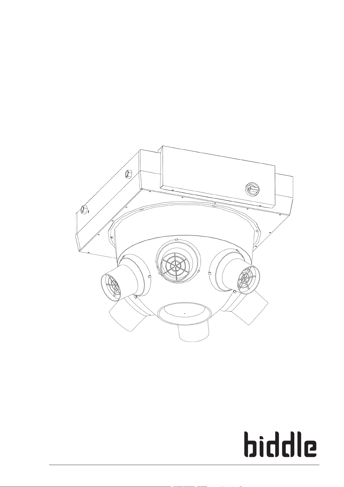
Manual
Air heater
Model NOZ2
Version 6.0 - North America
Original Manual
a
English
Page 2

en
. . . Contents
1 Introduction 4
1.1 About this manual 4
1.2 How to read this manual 4
1.3 About the unit 5
1.4 Components and accessories 11
1.5 Safety instructions 12
2 Installation 14
2.1 Inspection on delivery 14
2.2 General working method 14
2.3 Determining the location of the unit 16
2.4 Mounting the roof cowl (accessory) 17
2.5 Hanging the unit up 18
2.6 Regulating the discharge direction 21
2.7 Connecting the unit to the central heating system 23
2.8 Connecting the unit to the mains supply 28
2.9 Installing the b-control continuously variable controller 31
2.10 Installing the b-touch control panel 34
2.11 Installing external controls 37
2.12 Unit finishing 42
2.13 Switching ON and checking operation 42
AIR HEATER
3 Operation with b-control 46
3.1 Introduction 46
3.2 Switching ON and OFF 46
3.3 Regulating the strength 46
4 Operation with b-touch 47
4.1 Introduction 47
4.2 The Home screen 49
4.3 Main menu 52
4.4 Preferences 53
4.5 Settings 54
4.6 Configuration 55
4.7 Maintenance 60
4.8 USB 61
5Errors 64
5.1 Resolving simple problems 64
5.2 Error messages on the control panel 66
5.3 Remedying errors that are accompanied by an error message 67
5.4 Remedying errors that are not accompanied by an error message 70
en-2 B
Page 3
NOZ2 MANUAL
6 Maintenance 72
6.1 Introduction 72
6.2 Safety instructions 72
6.3 Cleaning the unit 72
6.4 Replacing or cleaning the filter 73
7 Service 74
7.1 Replacing the fan 74
7.2 Electronics module 75
7.3 Removing the control circuit board 76
7.4 Connecting the control circuit board 76
7.5 Fuses 77
7.6 LEDs 77
7.7 Setting the unit code 78
7.8 Resetting the PIN code 79
7.9 Copying the settings 79
7.10 Updating the software 80
7.11 Composition of the Biddle control cable 82
en
8 Dismantling 83
9 Addresses 85
Keywords 86
Manual version 6.0 - North America (10-03-2017) en-3
Page 4
en
Note:
Caution:
Warning:
1. . Introduction
1.1 About this manual
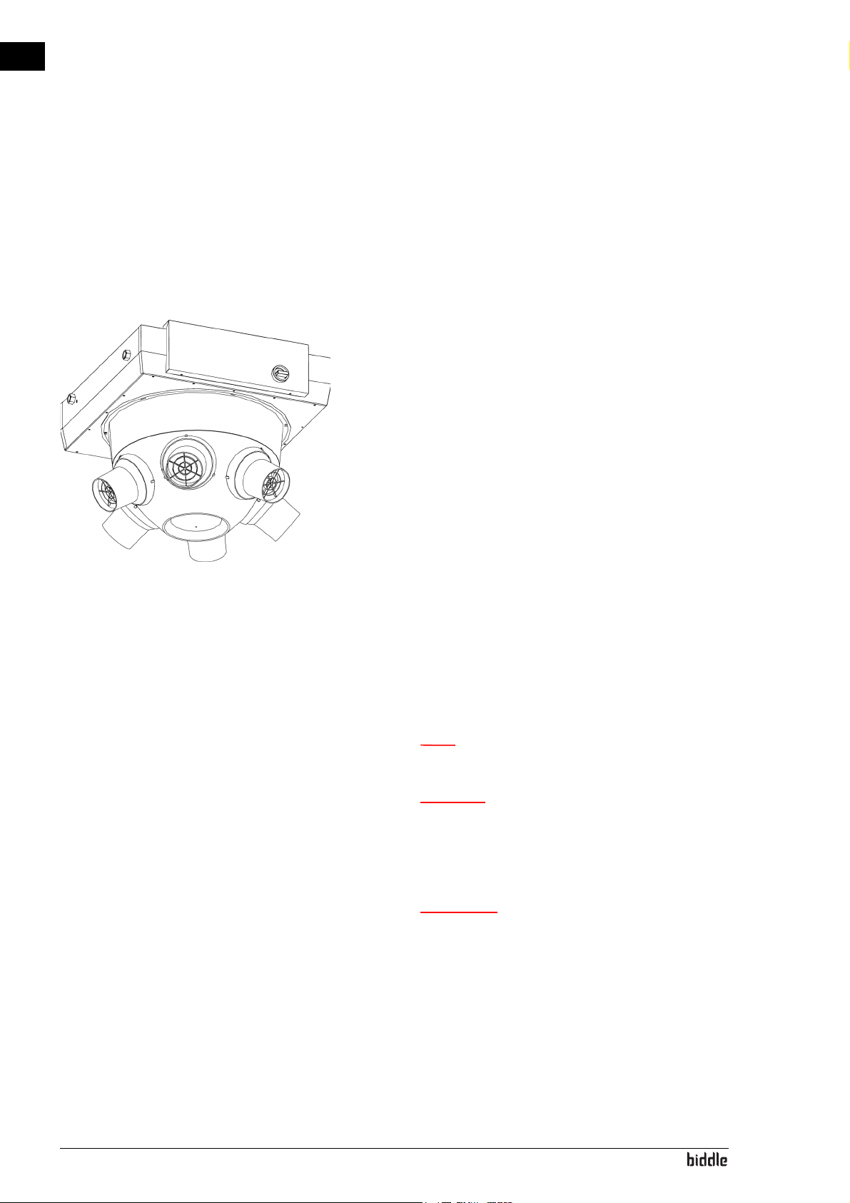
This manual describes the installation, operation and maintenance of the air heater model NOZ
vides instructions and information for servicing activities.
. The manual also pro-
2
1.2 How to read this manual
1.2.1 Designations used in the manual
The following symbols are used in the manual:
n Refers to an important section in the text.
c If you do not carry out the procedure or action
correctly, you may cause damage to the unit.
Follow the instructions precisely.
w If you do not carry out the procedure or
action correctly, you may cause physical injury
and/or damage.
Follow the instructions precisely.
en-4
Page 5
NOZ2 MANUAL INTRODUCTION
Danger:
d Is used to designate actions that are not
permitted.
Ignoring this prohibition may lead to serious
damage or to accidents resulting in physical
injury.
1.2.2 Symbols used on the unit and in the manual
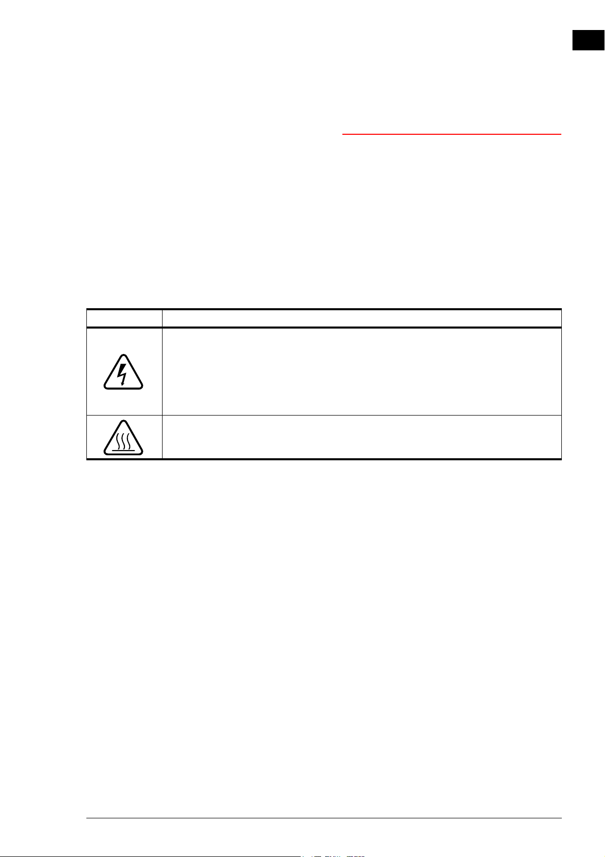
The following symbols indicate possible risks or hazards. The
same symbols will also be found on the unit.
S
YMBOL DESCRIPTION
en
w You have accessed a section of the unit containing components which carry
a voltage.
Access restricted to qualified maintenance staff only.
Caution is required.
w This surface or component may be hot. Risk of burns on contact.
1.3 About the unit
1.2.3 Related documentation
In addition to this manual, the following documentation is also
supplied with the unit:
• wiring diagram for installation and servicing.
1.3.1 Applications
The air heater is intended for the heating and (depending on
the unit type) ventilation of large, open spaces. The unit is
placed (free-hanging) at the top of the space concerned.
Manual version 6.0 - North America (10-03-2017) en-5
Page 6
en
INTRODUCTION AIR HEATER
1.3.2 Operation
General
The unit blows currents of warm air downwards. The airflow
rate ensures that the warm air spreads over a large area.
Depending on the setting, the unit can also blow unheated air.
Depending on the implementation, the unit can also ventilate.
The automatic CHIPS control
Depending on the implementation, the unit may be equipped
with an automatic CHIPS control.
The CHIPS control automatically adjusts the strength and heat
of the unit to changing weather conditions. Thus, in all situations the energy loss is minimal and the comfort maximal.
CHIPS stands for “Corrective Heat and Impulse Prediction System”.
Control when unit ‘on’
For the most efficient effect, it is important that the airflow
just touches the floor and is heated sufficiently. The unit continuously measures the values that are needed in order to
achieve this:
1. The installation height (entered in the control panel)
2. The room temperature
3. The temperature of the discharged air
As soon as the situation changes, the control adjusts the outlet flow rate and the temperature of the airflow to that.
Control with unit ‘off’
If the unit is off – at night, for example – it is not active as climate separation.
en-6
If it is off, the unit can indeed still perform other functions:
• The unit can be set to keep the room at a minimal ‘night’
temperature.
• Water-heated models are equipped with integrated frost
protection.
Page 7
NOZ2 MANUAL INTRODUCTION
Note:
n In some situations the unit does not discharge any
air, even though it is on.
1.3.3 Type designation
The table below provides an overview of the available models
of the unit and the corresponding type designations. In combination, the type designations constitute the type code, for
instance: NOZ
Explanation of the type code
T
YPE CODE ELEMENT DESIGNATION MEANING
product series NOZ
capacity 25 short range
battery type H2 water heating, element is 2 rows thick
control Basic basic control
mains supply 230/22 230V, split phase, 60 Hz
2
25V short range, suitable for ventilation
50 long range
50V long range, suitable for ventilation
H3 water heating, element is 3 rows thick
H6 water heating, element is 6 rows thick
A without heating
Auto automatic CHIPS control
480/32 480V, three-phase (without neutral wire), 60 Hz
480/52 480V, combination three phase/split phase, 60 Hz
general designation for the series
25-H2-Auto-230/22.
2
en
Manual version 6.0 - North America (10-03-2017) en-7
Page 8
en
INTRODUCTION AIR HEATER
1.3.4 Type plate
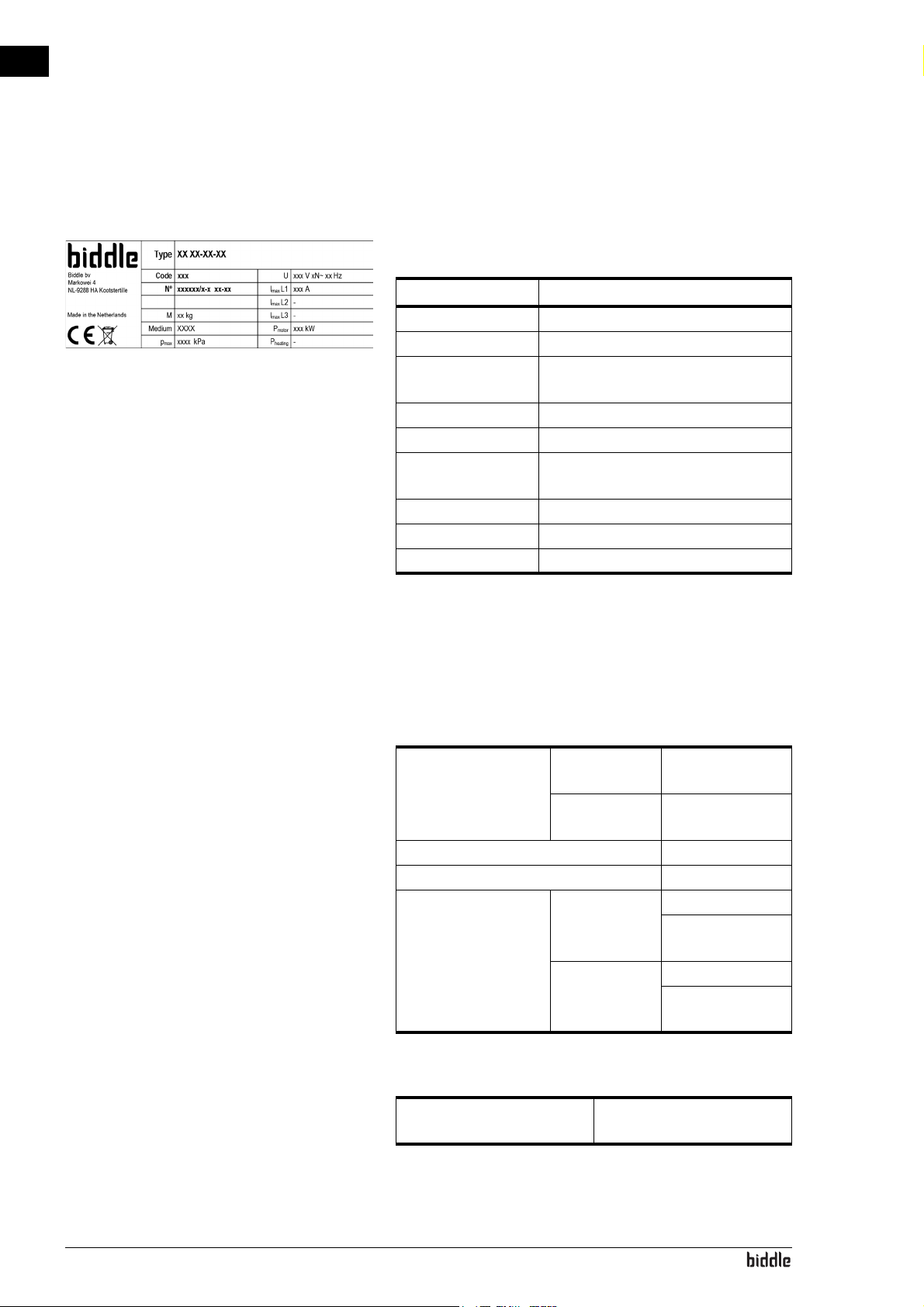
The type plate is located on the top of the unit.
Designations on the type plate
DESIGNATION MEANING
Type complete type code of the unit
Code configuration code
o
N
Mweight of unit
Medium medium
p
max
U power supply voltage
I
max
P
motor
serial number, production week and
year
maximum permissible operating pressure
max. current
max. power consumption by fans
1.3.5 Field of application
The air heater is utilised in large, open spaces. The following
operating limits must be observed:
Application limits for all models
Ambient conditions Temperature 5 °C to 40°C
(41 °F – 104 °F)
Relative air
humidity
20% – 95%, noncondensing
Power supply voltage see type plate
Power see type plate
Maximum discharge
temperature
NOZ
25 45 °C (113 °F)
2
60 °C(140 °F)
in lower modes
NOZ
50 40 °C (104 °F)
2
60 °C(140 °F)
in lower modes
Parameters of use for water-heated models
en-8
Maximum operating pressure
see type plate
Page 9
NOZ2 MANUAL INTRODUCTION
Caution:
Note:
Warning:
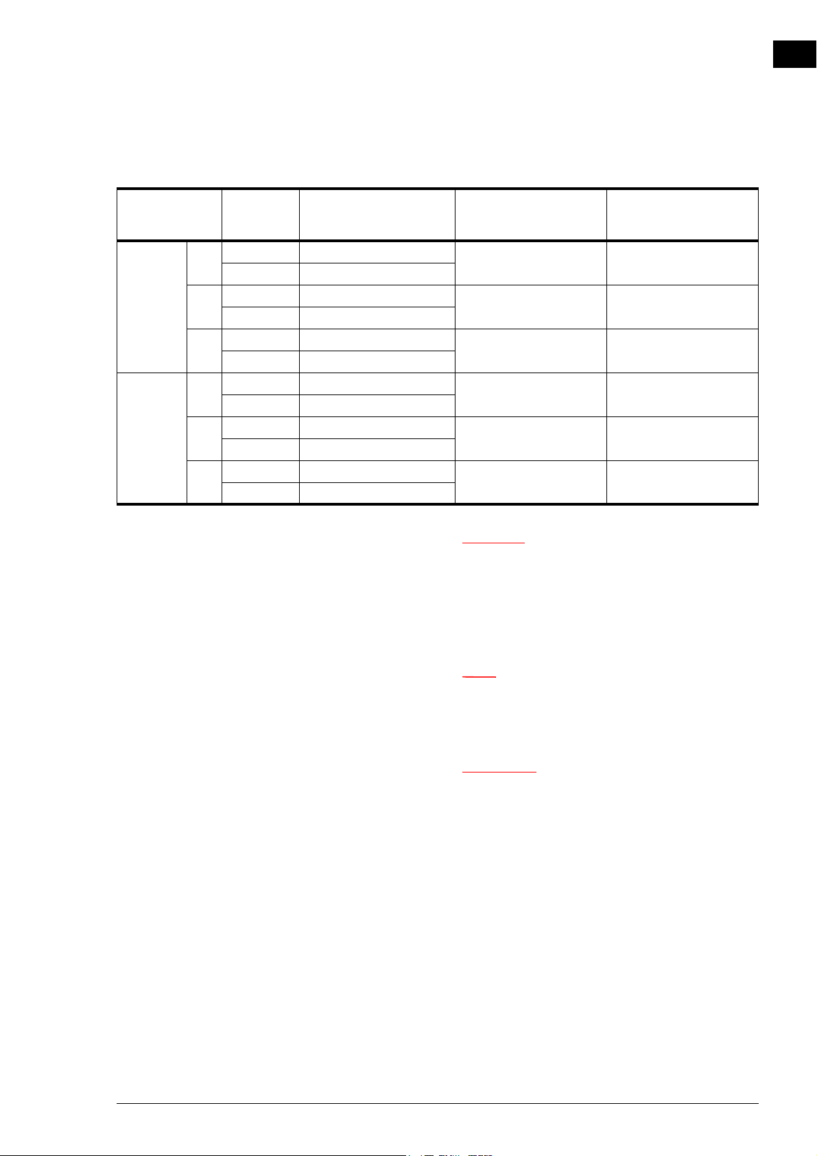
Maximum water flow-paths
en
TYPE OF UNIT
NOZ
25 H2 10V 45 °C (113 °F) 90/70 °C (194/158 °F) 125 °C/16 bar
2
NOZ
50 H2 10V 40 °C(104 °F) 90/70 °C (194/158 °F) 125 °C/16 bar
2
MAXIMUM
POWER
8V 60 °C(140 °F)
H3 10V 45 °C (113 °F) 70/50 °C (158/122 °F) 125 °C/16 bar
8V 60 °C(140 °F)
H6 10V 45 °C (113 °F) 60/40 °C (140/104 °F) 125 °C/16 bar
8V 60 °C(140 °F)
8V 60 °C(140 °F)
H3 10V 40 °C(104 °F) 80/60 °C (176/140 °F) 125 °C/16 bar
8V 60 °C(140 °F)
H6 10V 40 °C(104 °F) 60/40 °C (140/104 °F) 125 °C/16 bar
8V 60 °C(140 °F)
MAXIMUM
PERMITTED
TEMPERATURE
DISCHARGE
MAXIMUM WATER
FLOW-PATH
(
UNREGULATED)
c * A water flow-path up to 125 °C/16 bar (257 °F/16
bar) is only permitted if all units connected have
been set in such a way that the maximum discharge
temperature is not exceeded at the lowest fan
speed.
AXIMUM WATER
M
FLOW-PATH
(
REGULATED)
(257 °F/16 bar)*
(257 °F/16 bar)*
(257 °F/16 bar)*
(257 °F/16 bar)*
(257 °F/16 bar)*
(257 °F/16 bar)*
n Consult Biddle if you want to connect a unit to a
water flow-path with higher temperatures and higher
pressure.
w The air heater may not be used in potentially
explosive environments, outdoors or in very
dusty or aggressive air conditions.
Biddle shall not be held liable for damage
caused by use in such situations.
Manual version 6.0 - North America (10-03-2017) en-9
Page 10
en
Warning:
Caution:
Caution:
Note:
INTRODUCTION AIR HEATER
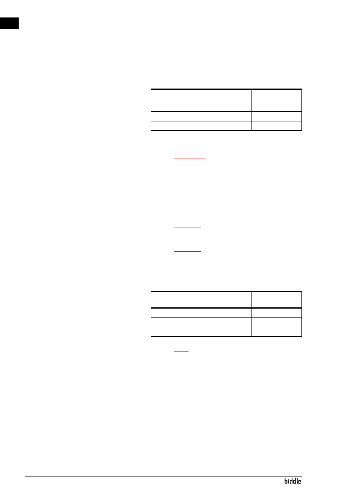
Sound levels
MAXIMUM SOUND
PRESSURE LEVEL
L
[DB(A)]
P
NOZ
25 58 76.1
2
NOZ
50 67 87.3
2
V = max. air flow; T60 = 1.2s; R = 5m; Q = 2
MAXIMUM SOUND
POWER LEVEL L
[
DB(A)]
W
w Prolonged exposure can cause damage to the
hearing. If necessary, wear hearing protection.
Maximum number of units that can be daisy chained
Take into account the maximum number of units that can be
daisy chained as shown in the table below:
c Only daisy chain units of equal capacity.
c With Auto type unit: The total cable length
between the first and the last unit may be 100m at
maximum.
NOZ
2
Basic 5 5
Auto 10 10
Basics per Auto 4 not possible
NOZ2 V
(
VENTILATION)
n Consult your Biddle advisor if you wish to connect
more units.
1.3.6 Modifications and changes
Without the approval of Biddle, no changes or modifications
may be made to the unit that could adversely affect safety.
en-10
Page 11
NOZ2 MANUAL INTRODUCTION
1.4 Components and accessories
1.4.1 Components supplied
• adjustment aid, nozzle angles.
1.4.2 Operating package
The unit can be supplied with a basic control or an automatic
CHIPS control. A corresponding operating package is supplied.
Operating package for basic control
• b-control continuously variable controller.
Operating package for automatic CHIPS control
en
• b-touch control panel;
• Biddle control cable;
• room sensor;
• water-side control (valve and drive).
1.4.3 Accessories
• suspension frame with vibration dampers.
• set of cover caps for nozzles;
• room thermostat;
• flanges;
• roof cowl;
• channel sections;
• filter module;
•damper module;
•servomotor.
1.4.4 Components not supplied
The following components required for installation must be
obtained from third parties:
• threaded rods (M8)
• other cabling
Manual version 6.0 - North America (10-03-2017) en-11
Page 12
en
Warning:
Warning:
Warning:
Caution:
Warning:
Danger:
Warning:
INTRODUCTION AIR HEATER
1.5 Safety instructions
1.5.1 Safety in use
w Do not put any objects into the inlets and
outlets.
w Do not obstruct the unit’s inlets or outlets.It
is permissible to cover a maximum of 2
nozzles with the caps supplied.
w The upper surface of the unit becomes hot
during operation.
c In exceptional situations, water may run out of the
unit. Therefore, do not place anything under the unit
that could be damaged as a result.
1.5.2 Safety issues relating to installation, mainte-
nance and servicing
w Mount the unit so that the underside hangs at
least 2.8 m above the floor. It should not be
possible to reach the nozzles without the use
of mechanical aids.
d The unit may only be opened by qualified
technical staff.
en-12
w Perform the following actions before opening
the unit:
Page 13
NOZ2 MANUAL INTRODUCTION
Danger:
Caution:
Caution:
Warning:
1. Switch the unit off,using the control panel.
2. Wait until the fan has stopped.
d The fan may continue rotating for a while.
3. Allow the unit to cool down.
c The heat exchanger or, as the case may be, the
heating elements, can get very hot.
4. Disconnect the mains supply (switch off the isolation
switch).
en
c For models NOZ
control:
The units are equipped with 2 mains power cables.
Disconnect the mains supply to both mains power
cables.
5. If you are going to carry out maintenance or repairs on
electrical components: switch the mains supply group off.
6. For water-heated models:
shut off the central heating feed (if possible).
50 with automatic CHIPS
2
w The fins of the heat exchanger are sharp.
Manual version 6.0 - North America (10-03-2017) en-13
Page 14
en
Warning:
Warning:
2. . Installation
w Installation activities may only be performed
by technical staff qualified for this purpose.
w Before starting installation: read the safety
instructions.
See also:
1.5 "Safety instructions" on page 12
2.1 Inspection on delivery
2.2 General working method
• Check the unit and the packaging to ensure that they have
been delivered in good order. Notify the driver and the
supplier immediately if any shipping damage is detected.
• Ensure that all components are present. Notify supplier of
any missing parts immediately.
See also:
1.4.3 "Accessories" on page 11
2.2.1 Sequence of operations
Biddle recommends working as follows when installing the
unit:
1. Install roof cowl, if applicable.
2. Install accessories, if applicable.
en-14
3. Hang the unit up.
4. For water-heated models (type H):
connect the unit to the central heating system.
Page 15
NOZ2 MANUAL INSTALLATION
Caution:
Note:
Note:
5. Connect the unit to the mains supply.
c Make sure that the unit’s power supply voltage
matches the local mains voltage.
The unit’s power supply voltage is displayed on the
type plate.
6. Install the control panel and (any optional) connections to
external controls.
7. Complete the installation of the unit.
8. Switch the mains supply on and check that the unit is
working properly.
General instructions
en
Some parts of this section only apply to certain models.
Where this is the case, it will be indicated. If no specific model
is referred to, then the description applies to all models.
n Make sure that you perform all installation
operations that are applicable to your unit.
Check the type plate and consult the manual if in
doubt about the model or type of your unit.
n During the installation period, protect the unit
against damage and penetration of dust, cement, etc.
You can, for instance, use the packaging for
protection.
See also:
1.3.4 "Type plate" on page 8
Manual version 6.0 - North America (10-03-2017) en-15
Page 16
en
Warning:
Note:
INSTALLATION AIR HEATER
2.3 Determining the location of the unit
• Make sure that the structure from which the unit is about
to be suspended can bear at least 4 times the weight of the
unit. The unit’s weight is indicated on its type plate.
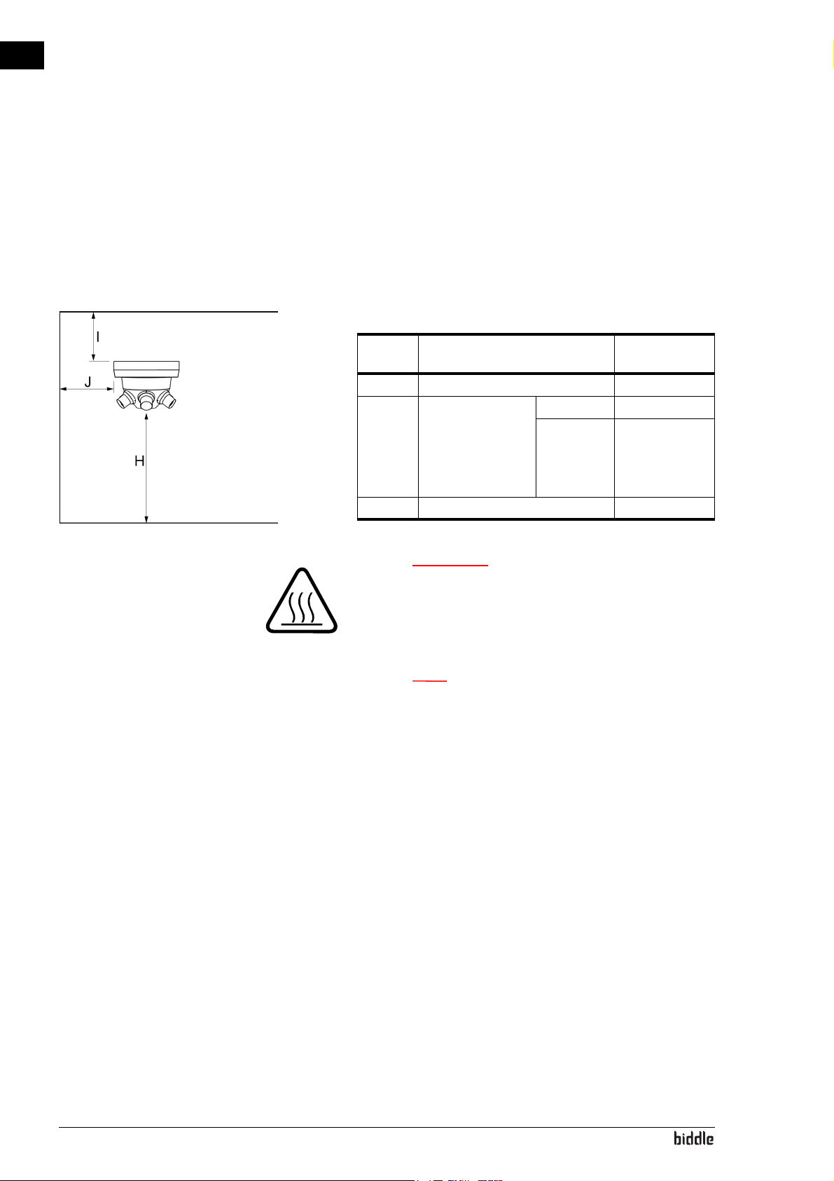
• The unit must hang freely in the room. Note the following
dimensions:
SIZE DESCRIPTION
H installation height 280 cm (10 ft.)
Iminimum dis-
tance between
unit and ceiling (in
the case of intake
from the room)
J minimum distance to walls 3 m (10 ft.)
NOZ
NOZ
2
2
MINIMUM
LUE
25 20 cm (8")
50 30 cm (12")
VA-
w The top of the unit may get hot. The unit
must have at least 20 cm (8") (NOZ
30 cm (12") (NOZ
ceiling.
50) clearance from the
2
25) or
2
n In the case of multiple units, where the water valve
must be connected in series, you are advised to hang
the unit with the control circuit board (type Auto) in
the middle.
en-16
See also:
1.3.4 "Type plate" on page 8
Page 17
NOZ2 MANUAL INSTALLATION
2.4 Mounting the roof cowl (accessory)
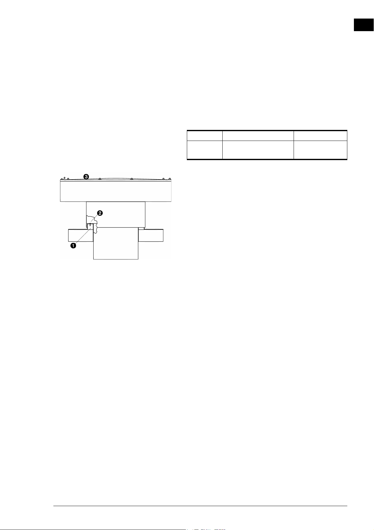
You have the option of installing a roof cowl if the unit is used
for ventilation.
Conduit sizes
NOZ
25 NOZ2 50
2
conduit 575 x 575 mm
(22 41/64" x 22 41/64")
1. Make a hole in the roof.
2. Make a curb 1 around the hole.
3. Fit roof covering over the curb.
800 x 800 mm
(31 1/2" x 31 1/2")
en
4. Remove the top 3 of the roof cowl by loosening the bolts.
5. Place the roof cowl over the curb.
6. Using screws, attach the cowl to the curb, as at 2.
7. Mount the top 3 onto the roof cowl.
8. Seal all cracks between the roof cowl and the roof with a
draught-free and leak-proof finish.
Manual version 6.0 - North America (10-03-2017) en-17
Page 18
en
Caution:
INSTALLATION AIR HEATER
2.5 Hanging the unit up
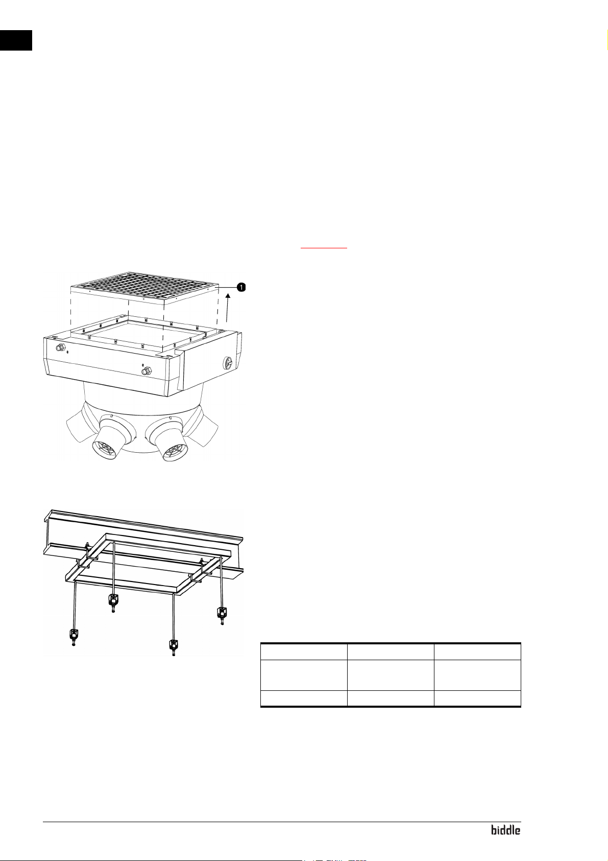
2.5.1 Detaching the inlet grille
If you are making use of ventilation accessories, only for
units without heating (type A), you must first remove the
inlet grille.
c In all other cases, do NOT remove the inlet grille.
1. Remove the screws around the inlet grille 1.
2. Remove the inlet grille.
2.5.2 Hanging the unit up
1. If you are using the suspension frame (accessory):
- Attach the suspension frame.
If you are not using a suspension frame:
- Insert four threaded rods. Make sure that the threaded
rods are hanging perpendicularly.
Dimensions for suspending from threaded rods
NOZ2 25 NOZ2 50
distance between
threaded rods
screw thread M8 M8
2. Onto each threaded rod, screw two bolts a few centimetres apart.
710 x 640 mm
(28" x 25 13/64")
935 x 865 mm
(36 13/16" x 34")
en-18
Page 19
NOZ2 MANUAL INSTALLATION
Warning:
Caution:
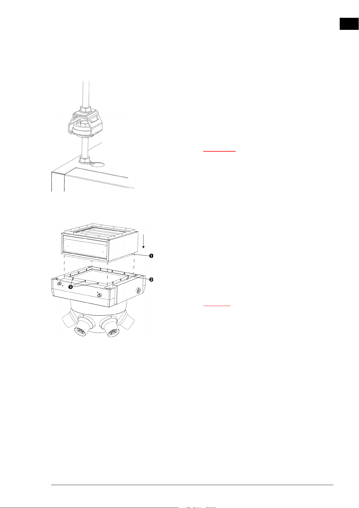
3. Hang the unit from the threaded rods:
- Hook the threaded rods with the lowest set of bolts in
the key holes on the top of the unit.
- Internally, there is a locking edge under every keyhole.
The bolts must lock in place behind these.
4. Secure the unit by tightening the top bolts against the plating.
w The suspended unit must be secured.
en
2.5.3 Mounting the filter module (accessory)
The unit can be fitted with a filter module. The section can be
mounted on the unit or on a damper module.
The illustrations alongside the instructions are based on the
mounting to the unit. The actions required for mounting to a
damper module are the same as this.
1. Place the flange 1 of the filter module over the flange 2
of the unit.
c Position the filter module in relation to the unit as
indicated in the illustration. If the module is
positioned in a different direction, cables can
become pinched off.
2. Attach the flanges together, using 12 screws 3.
Manual version 6.0 - North America (10-03-2017) en-19
Page 20
en
INSTALLATION AIR HEATER
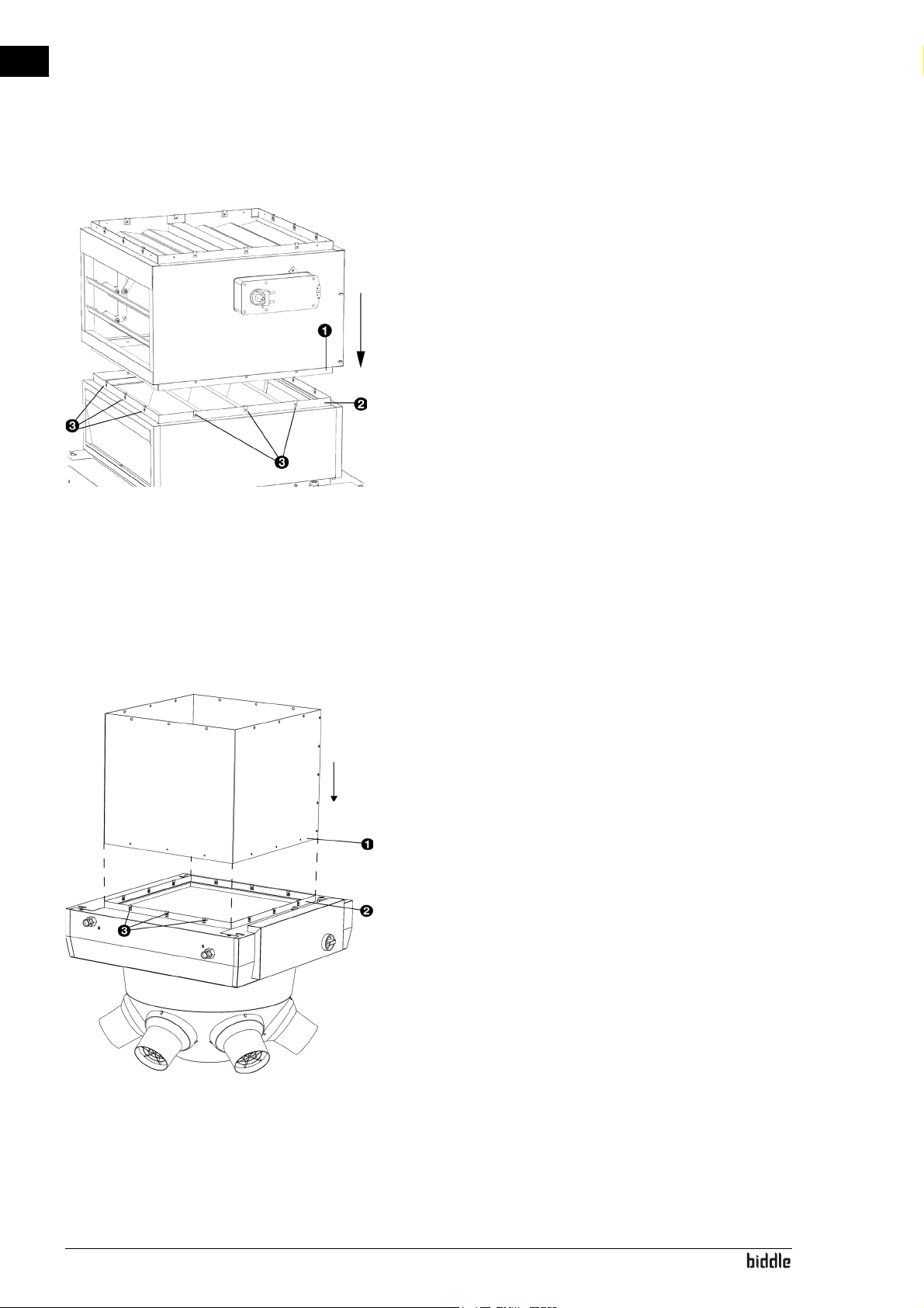
2.5.4 Mounting the damper module (accessory)
The unit can be equipped with a damper module. With this, a
connection to a ventilation duct can be opened and closed.
The damper module is supplied in two variants:
• a 1-way module (only suitable for ventilation), and
• a 3-way module (suitable for ventilation and recirculation).
The damper module can be mounted on the unit or on a filter module.
The illustrations alongside the instructions are based on the
mounting of a 3-way damper module on a filter module. The
actions required for the mounting of a 1-way damper module
to the unit are the same as this.
1. Place the flange 1 of the damper module over the flange
2 of the unit.
2. Attach the flanges together using 12 screws 3.
3. Connect the servomotor in accordance with the electrical
diagram supplied.
2.5.5 Installing the ventilation ducts (accessories)
If the unit is used for ventilation, you can optionally install a
ventilation duct.
1. Place the interconnecting duct 1 over the flange 2 of the
unit or the damper module.
2. Attach the interconnecting duct to the flange, using 12
screws.
en-20
Page 21
NOZ2 MANUAL INSTALLATION
Caution:
Note:
Note:
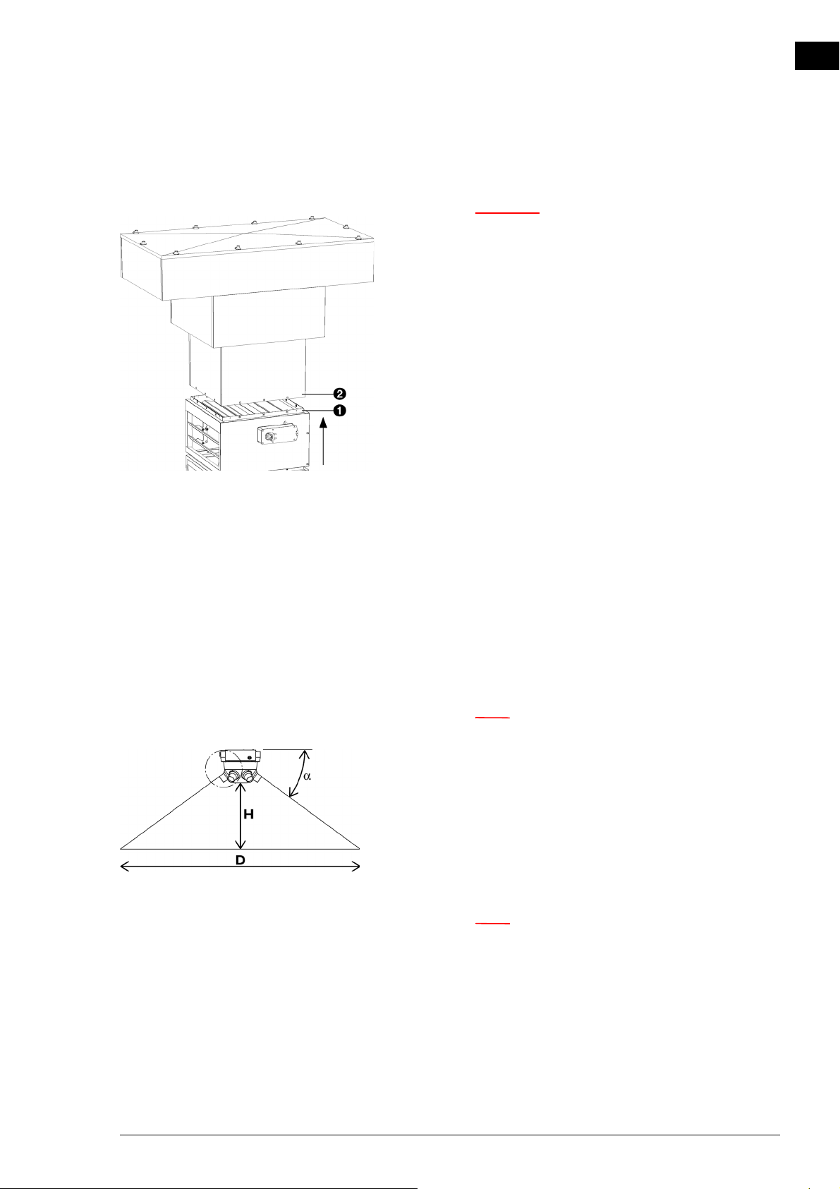
2.5.6 Mounting the unit to the roof cowl
c The unit cannot be suspended from the roof cowl.
One must always make use of a suspension
construction, such as a suspension frame, for
example.
1. Determine the height at which the unit must hang, and if
necessary, attach a channel section of the correct length to
the roof cowl.
2. Bring the unit to the correct height, so that the flange 1
comes within the rim of the roof cowl 2.
3. Attach the roof cowl to the flange, using 12 screws.
en
See also:
2.4 "Mounting the roof cowl (accessory)" on page 17
2.6 Regulating the discharge direction
Set the nozzles to the angle which produces the most optimal
effect of the unit for the situation. For this purpose, the nozzles are equipped with a ball-and-socket joint.
The optimal angle of the nozzles depends on the mounting
height of the unit and on the floor surface area to be reached.
n Measure all the values in metres.
1. Determine the diameter (D) of the floor surface area that
must be reached;
2. Measure the mounting height (H) of the unit. This is the
distance between the floor and the underside of the unit;
3. From the table, read out the angle (α) at which the nozzles must be set;
n For the NOZ
printed in bold type is applicable.
Manual version 6.0 - North America (10-03-2017) en-21
25, only the section of the table
2
Page 22
en
Caution:
Note:
INSTALLATION AIR HEATER
Nozzle angle
D [m] 10 12.5 15 17.5 20 22.5 27.5 30 32.5
H [m]
3.0 42363127242220 18 17 15
4.0 50443934312826 24 22 20
5.0 - 50 45 41 37 34 31 29 27 25
6.0 --50 46 42 39 36 33 31 29
7.0 ---50 46 43 40 37 35 33
8.0 ----50 47 44 41 39 36
9.0 ----535047444240
10.0 -----5350474543
11.0 ------53504845
12.0 -------535048
13.0 --------5250
14.0 ---------52
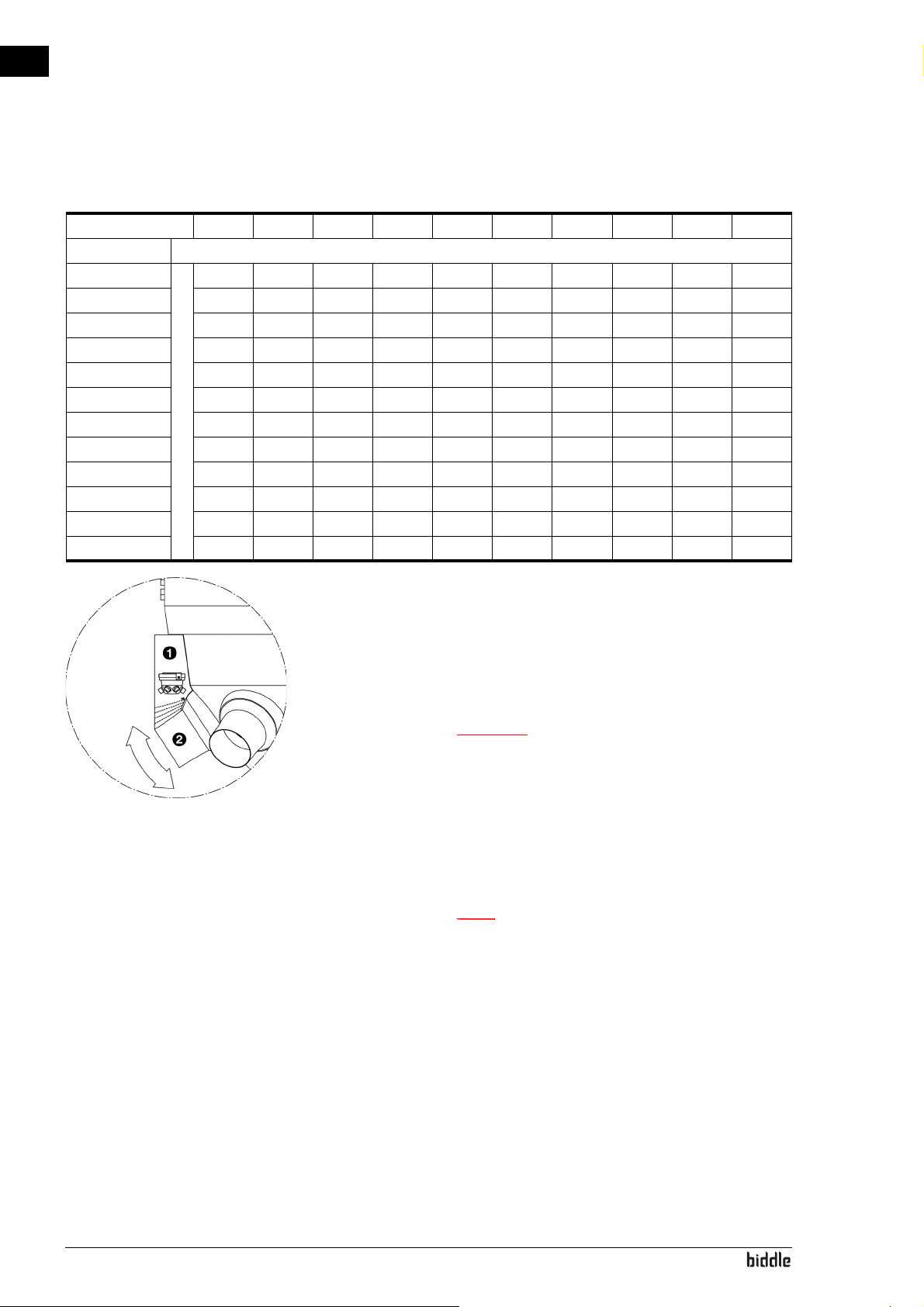
4. Snip off the adjustment aid 1 (supplied) along the dotted
line which corresponds to the correct angle (α);
5. Hold the snipped-off adjustment aid 1 against the unit and
turn the nozzle 2 against the underside of the adjustment
aid;
c Do not aim the nozzles at walls or other obstacles
(such as scaffolding). If a nozzle is unavoidably aimed
at an obstacle, you can close off the nozzle with a
cap. You can close a maximum of 2 nozzles. A set of
2 caps is available as an accessory.
6. Repeat step 5 for all nozzles.
n For models with automatic CHIPS control:
Note down the nozzle angle (α) and the mounting
height (H) (in metres). For optimal operation of the
automatic regulation, these values must be entered
during the installation of the control unit.
en-22
Page 23
NOZ2 MANUAL INSTALLATION
Caution:
Danger:
Note:
Note:
2.7 Connecting the unit to the central heating system
Only for water-heated models (type H)
2.7.1 Special points regarding the water connection
The central heating system’s supply and return pipes must be
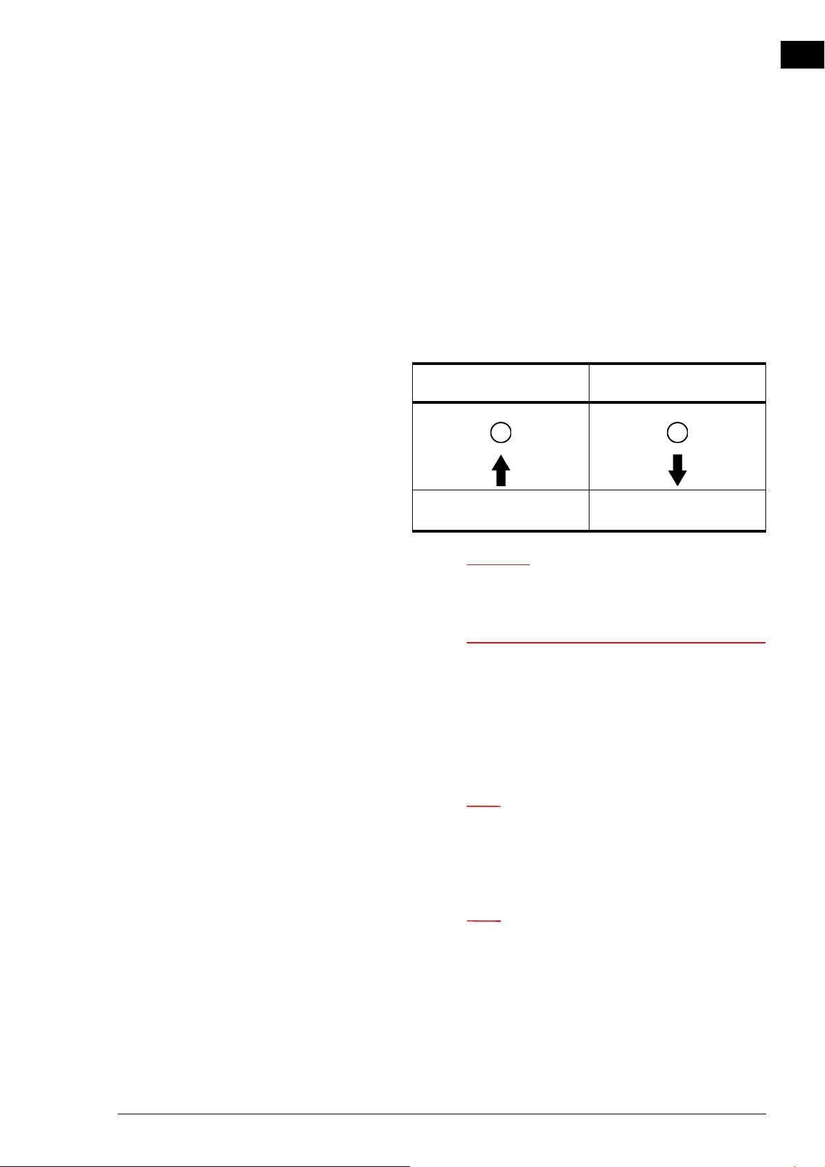
attached to the correct corresponding connectors. On the
unit, the directions are indicated with arrows.
en
SYMBOL
FEED PIPE
arrow points towards the
connection
SYMBOL
RETURN PIPE
arrow points away from the
connection
c Biddle recommends the inclusion of a valve in both
pipes.
d Take measures to limit the discharge
temperature.
Take account of the critical discharge
temperatures and water flow-paths. The
application limits for this are shown in section
1.3.5 Field of application.
n The central heating system must be fitted with an
overpressure cut-out with an initial pressure not
exceeding the permitted pressure of the unit. This is
shown on the type plate at P
max
.
n Make sure that the central heating system has
sufficient capacity.
Manual version 6.0 - North America (10-03-2017) en-23
Page 24
en
Note:
Caution:
Note:
INSTALLATION AIR HEATER
2.7.2 The water-side control (accessory)
The unit is equipped with a water-side control. This regulates
the water supply to the heat exchanger, so that a constant discharge temperature is achieved. The control can also be used
to limit the discharge temperature. The maximum permitted
discharge temperature is indicated in 1.3.5 Field of application.
For models with automatic CHIPS control, this limitation is
automatically set.
n In an assembly with automatic CHIPS control, the
water-side control valve is automatically closed by
default if the unit and/or the heating is switched off.
Special points regarding the water-side control
Biddle supplies water-side controls for models with automatic
CHIPS control.
c A maximum of 5 units having a control valve can be
connected in series per control circuit board.
Consult Biddle if you want to connect more control
valves in an assembly with a single control circuit
board.
Control valves that are not supplied by Biddle must, in any case,
comply with the following:
• 24V power supply.
• 0-10V control.
• The total power consumption of the water-side controls
that are connected to 1 control circuit board may be a
maximum of 7.6 VA.
Connecting the water-side control
For models with automatic CHIPS control:
en-24
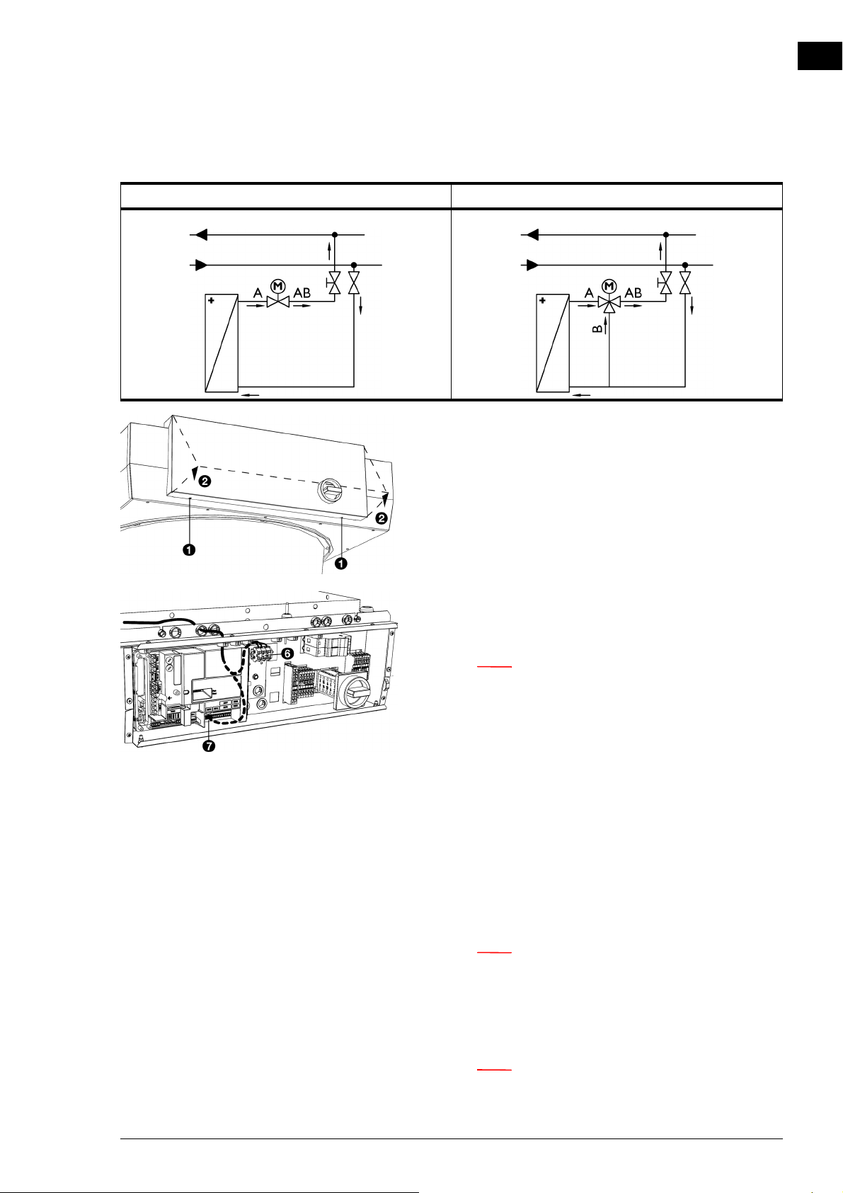
1. Connect the control valve and the drive to the heat
exchanger, in accordance with the diagram. In doing so, follow the instructions given in the control valve manual.
n Ensure that the axis of the valve is in the correct
position when connecting the drive. See the control
valve manual.
Page 25
NOZ2 MANUAL INSTALLATION
Note:
Note:
Note:
WIRING DIAGRAM 2-WAY VALVE WIRING DIAGRAM 3-WAY VALVE
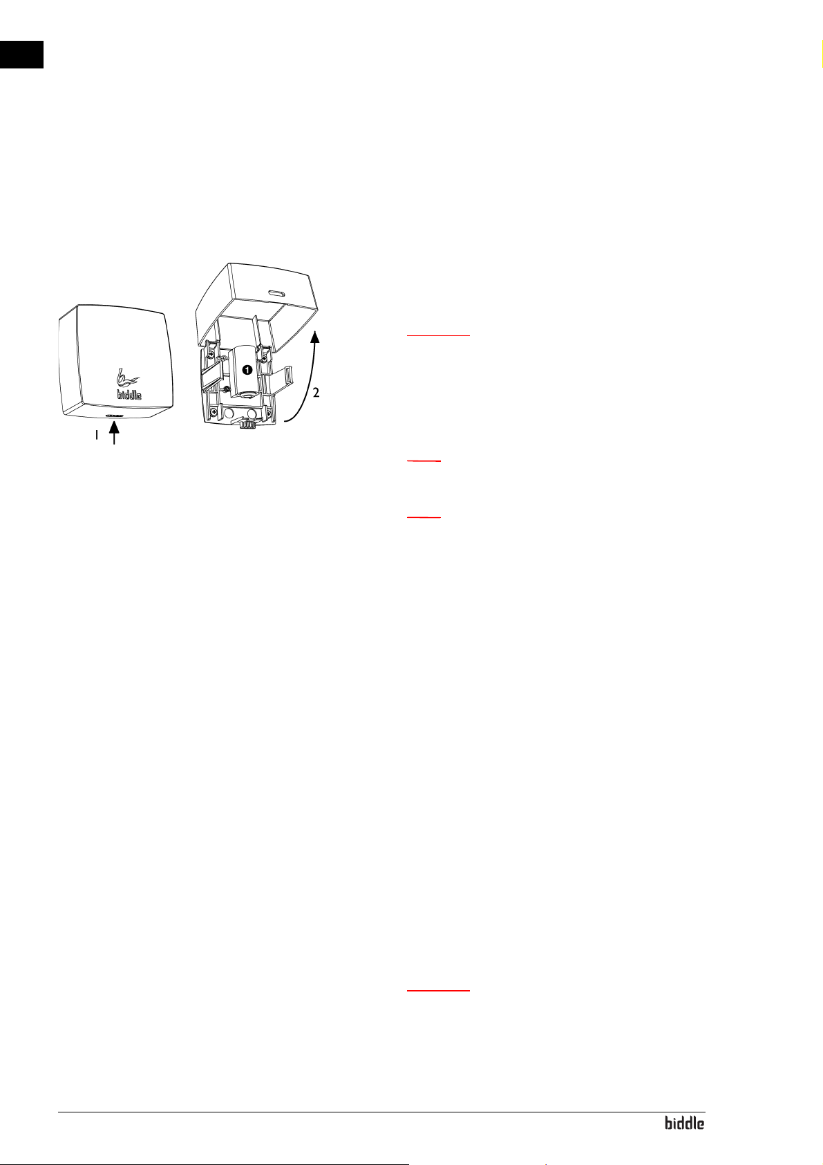
2. Open the electronics housing: undo screws 1 at the bottom of the housing, tilt the cover 2 and lift the cover off
the unit.
en
3. Connect the cord to the drive, in accordance with the wiring diagram.
n Use a cable of at least 0.5 mm
4. Feed the cord from the drive through the openings in the
electronics housing.
5. Connect the cord to the control circuit board, in accordance with the wiring diagram:
For models with recirculation: Use connection X67 6.
For models with ventilation: Use connection X370 7.
6. For models with recirculation: Connect (if applicable) the
drive among multiple units. Link the units, using a connecting cable, to connections X676.
2
.
n Models with ventilation (types 25V and 50V) are
always equipped with a control circuit board. With
each unit, connect the drive of the water valve to
the unit’s own control circuit board.
n Only close the electronics housing after connecting
the mains supply and the control unit and possible
external controls.
Manual version 6.0 - North America (10-03-2017) en-25
Page 26
en
Warning:
Note:
INSTALLATION AIR HEATER
For models with a basic control:
For models with a basic control, a capillary valve (not supplied) can be connected.
1. Connect the valve and the control element to the heat
exchanger. In doing so, follow the instructions given in the
control valve manual.
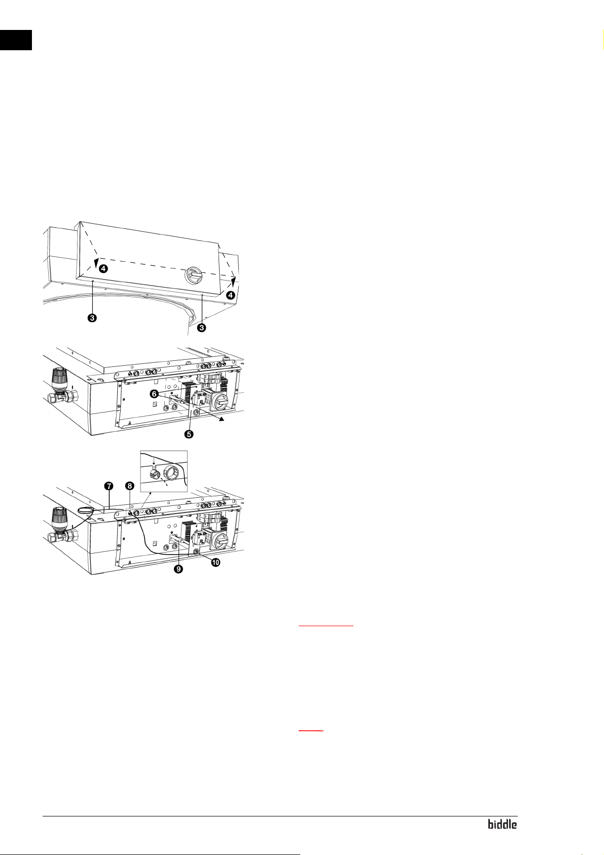
2. Open the electronics housing: undo screws 3 at the bottom of the housing, tilt the cover 4 and lift the cover off
the unit.
3. Remove the bracket 5 from the hole in the rear wall of
the housing: undo the screws 6 and push the bracket out
of the housing.
4. Lead the capillary tube 7 through the hole 8in the electronics housing. For this purpose, the grommet in the hole
is provided with an opening. If necessary, twist the grommet with the opening upwards.
5. Lead the sensor 9 with the capillary tube through the
opening 0 in the bracket.
6. Click the sensor 9 into the clamp on the bracket.
7. Place the clamp back in the rear wall of the housing and
fasten the screws.
w The capillary tube must not make contact
with elements carrying a voltage. Keep any
superfluous length of the capillary tube
outside the housing of the electronics.
en-26
8. Set the control element to the desired temperature.
n Only close the electronics housing after connecting
the mains supply and the control unit and possible
external controls.
Page 27
NOZ2 MANUAL INSTALLATION
Caution:
See also:
1 "Special points regarding the water connection" on page 1
1.3.5 "Field of application" on page 8
2.7.3 Frost protection
For models with automatic CHIPS control (Auto type)
The electronic control features integrated frost protection.
This works in two stages:
1. If the temperature of the discharged air falls to below 5 ºC
(41 ºF) and the temperature of the intake air falls below
8ºC(46ºF):
- the valve of the integral water-side control will open
fully;
- the output on the unit gives a signal for the central
heating installation provided that function 61. Function
of outputs on the control panel is set to Risk of freezing.
en
2. If the temperature of the discharged air falls to below 2 ºC
(36 ºF) and the temperature of the intake falls below
8ºC(46ºF):
- the control panel will temporarily display error mes-
sage E6;
- the fans will be switched off, but the valve of the water-
side control will stay open.
c The frost protection reduces the risk of freezing but
does not guarantee complete protection.
Take the following precautions if you install the unit
in a room where frost may occur:
- Ensure constant circulation of the water at the right
temperature;
- Add up to 50% glycol to the water when the unit is
not in operation during the wintertime;
- Or bleed the system and the unit.
For ventilation models with basic control (type NOZ2
V- B as i c)
The unit is fitted with a frost thermostat which is activated if
the temperature of the discharged air falls to below 6 ºC(43
ºF). This can be integrated into its own control.
Manual version 6.0 - North America (10-03-2017) en-27
Page 28
en
Warning:
Warning:
Warning:
Note:
Note:
INSTALLATION AIR HEATER
2.7.4 Connecting the unit
1. Connect the unit to the central heating system.
2. Check the connections for leakage.
2.8 Connecting the unit to the mains supply
2.8.1 Special points regarding the mains supply
For all models
w The unit must be earthed.
w The unit must be connected in accordance
with the applicable local requirements.
Maximum ratings are specified on the type
plate.
w Each unit must be fused in accordance with
the table below.
Fuse ratings
M
AXIMUM AMPERAGE ON
TYPE PLATE L1, L2 OR L3
≤ 10A 16A
AXIMUM FUSE VALUE A
M
n A single fuse may only be used for multiple units if
they draw a total current of less than 10A.
n The earth leakage circuit breaker (if applied) must be
type B, preferably 300 mA.
en-28
• It must be possible to disconnect the unit from the mains
supply. The installer must provide a facility for doing this.
Page 29
NOZ2 MANUAL INSTALLATION
Danger:
Caution:
Warning:
Warning:
Warning:
Note:
For all models
d Only carry out the connection if you are
qualified to work on three-phase power
systems.
• The unit is connected to the mains supply with a cable (not
supplied).
c For emergency situations and maintenance, it must
be possible to render the entire system electrically
dead.
• Every unit has an isolation switch in order to make maintenance easier.
en
w Also, do be sure to switch off the mains supply
if you are going to conduct maintenance on,
or make repairs to, electrical components.
2.8.2 Connecting the unit
w Make sure that the mains supply is switched
off.
w The mains power cables must be resistant to
the high temperatures in the unit. See
1.3.5 Field of application for the maximum
temperatures.
n Connect each unit separately to the mains supply.
Manual version 6.0 - North America (10-03-2017) en-29
Page 30
en
Warning:
Caution:
Note:
Caution:
Note:
INSTALLATION AIR HEATER
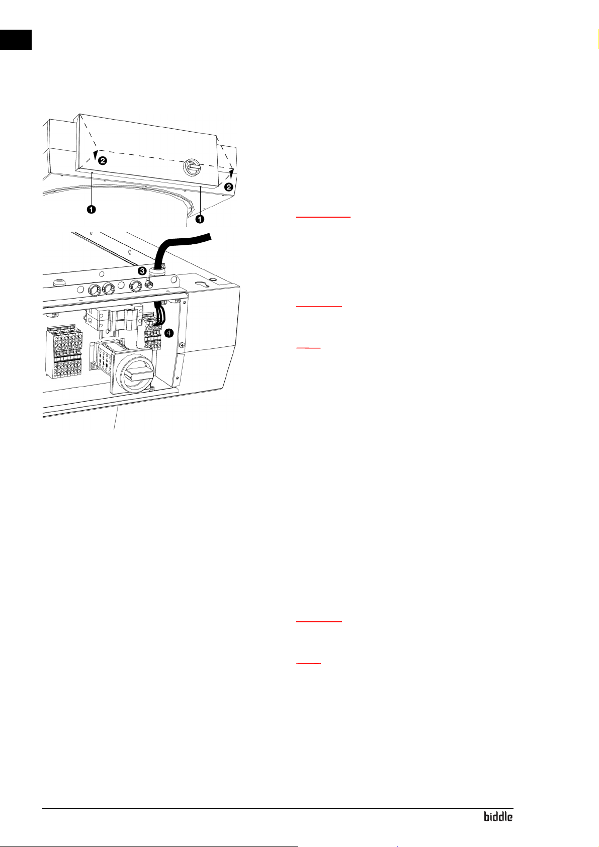
1. Open the housing of the electronics: undo the screws 1 at
the bottom of the housing, tilt the cover 2 and lift the
cover of the unit.
2. Lead the cable into the housing of the electronics via the
cable gland 3 at the top of the unit.
w Make sure the earth wire is longer than the
power supply wires.
3. Connect the mains power cable to the terminal block X01
4, in accordance with the wiring diagram supplied.
c Do not switch on the mains supply yet.
n Do not close the housing of the electronics yet.
Connect the control circuit board
Only regarding NOZ
trol
The control circuit board for the automatic CHIPS control
must be separately connected to a power supply of 230 V.
1. Lead the cable into the housing of the electronics via the
cable gland at the top of the unit.
2. Connect the mains power cable to the terminal block X06,
in accordance with the wiring diagram supplied.
50 with automatic CHIPS con-
2
c Do not switch on the mains supply yet.
en-30
n Do not close the housing of the electronics yet.
Page 31
NOZ2 MANUAL INSTALLATION
2.8.3 Connecting the servomotor (accessory)
For models with automatic CHIPS control (Auto type)
If you have installed a damper module with servomotor
(accessories), you must connect this to the controller.
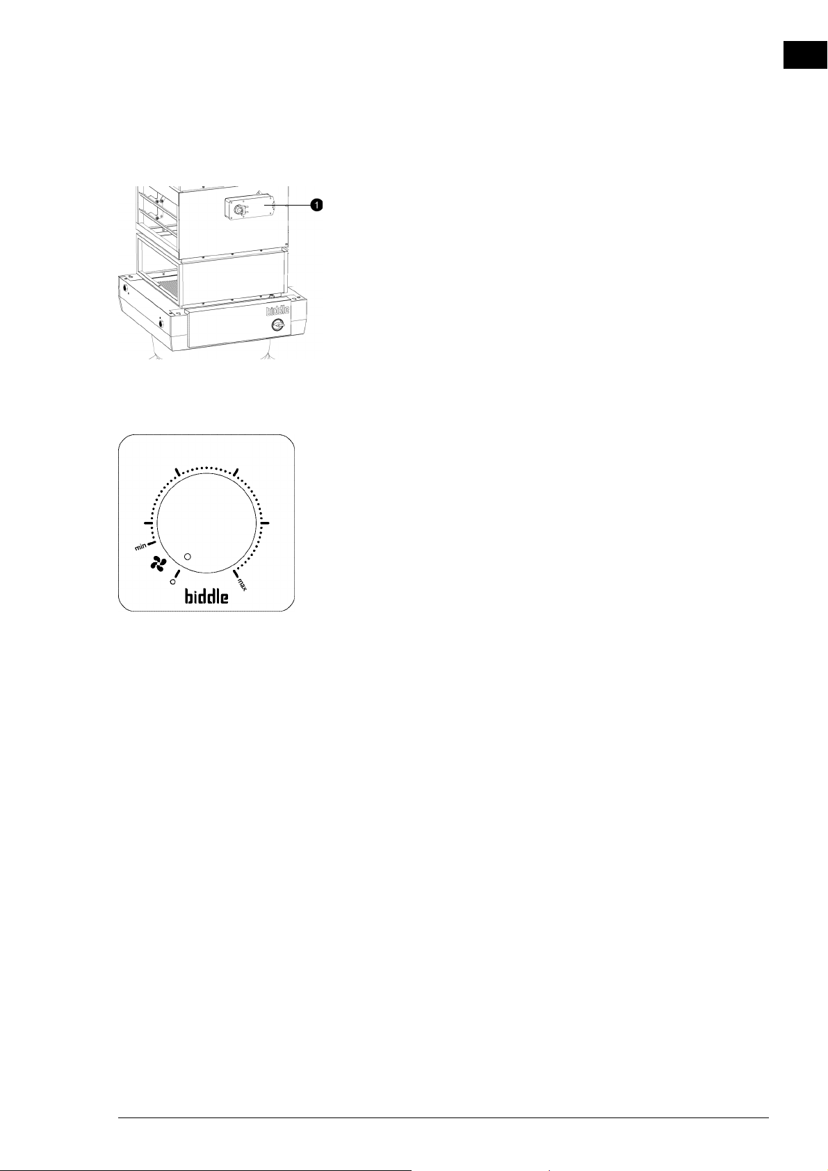
1. Connect the plug of the servomotor 1 to the cable
intended for that purpose on the unit.
For models with basic control (Basic type)
Connect the chosen motor for the damper module.
2.9 Installing the b-control continuously variable controller
Various control units are available for the NOZ2 air heater.
This chapter describes the installation of the b-control continuously variable controller that is used on units having a basic
control (Basic type).
en
2.9.1 Special points regarding the controller
Positio ning
You can fasten the controller either to the wall or to a standard junction box.
Cabling
The controller is connected to the unit via a cable (not supplied), and can be connected in series among several units.
Take the following into account, otherwise errors may occur:
• Keep the length of the cables as short as possible.
• Keep the cables away from electromagnetic fields and
interference sources, such as high-voltage cables and fluorescent light starters.
Manual version 6.0 - North America (10-03-2017) en-31
Page 32
en
Note:
Warning:
Caution:
Caution:
Caution:
INSTALLATION AIR HEATER
Multiple units with a single controller
A maximum of 5 units may be connected to a single controller.
n Consult your Biddle advisor if you wish to connect
more units.
Setting output voltage
The controller can adjust the strength of the unit in a continuously variable manner. The output voltage can be set between
Vmin and Vmax. This is done after the complete installation of
the unit and all connections.
2.9.2 Mounting and connecting the controller
w Make sure that the mains supply on which you
are working has been turned off.
c When installing the unit, use the wiring diagram
supplied.
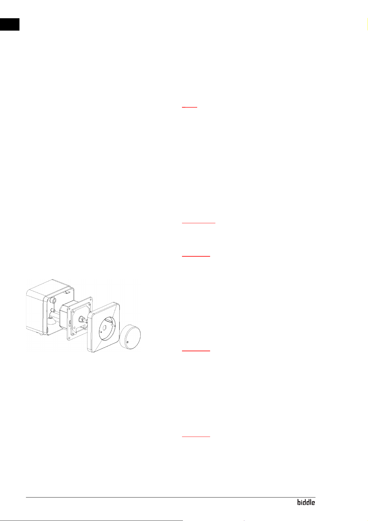
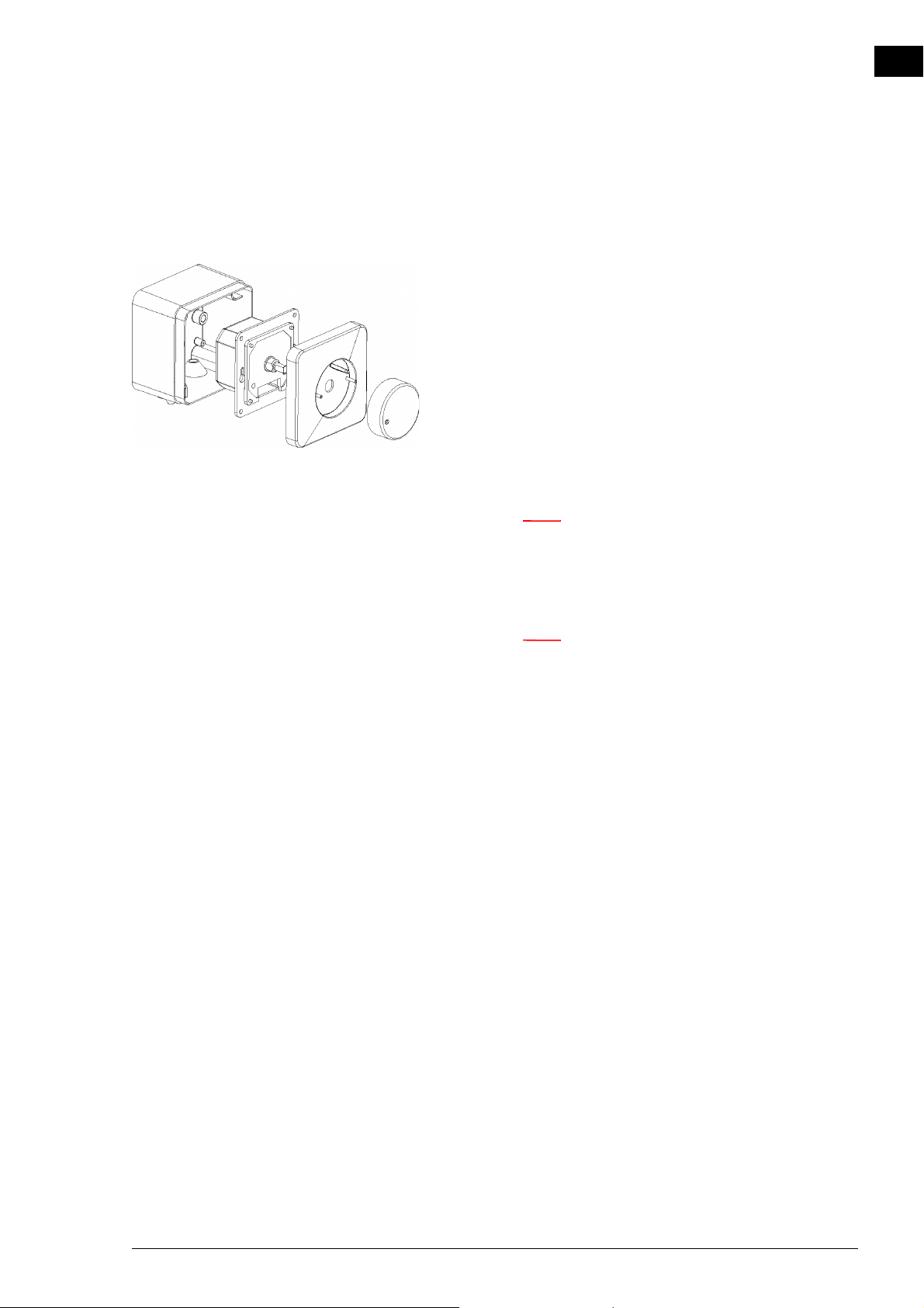
1. Remove the adjustment button.
2. Remove the hexagonal nut.
3. Remove the shut-off cap.
4. Fasten the surface-mounted box to the wall if you are not
making use of a standard junction box.
c (1/5”)
5. Lead the control cable (not supplied) between the controller and a unit of your choice. For the specifications of the
cable, see section 2.9.1 Special points regarding the con-
troller.
en-32
6. Connect the control cable to the controller. See the wiring diagram supplied.
c Do not turn the controller off yet if you still want to
adjust the output voltage after complete installation
of the unit.
Page 33
NOZ2 MANUAL INSTALLATION
Warning:
Note:
7. Using the 2 small screws and rings, screw the switch to the
surface-mounted box or standard junction box.
8. Fit the shut-off cap.
9. Fasten the hexagonal nut.
10. Fit the adjustment button: Press this on firmly and set to
position ‘0’.
2.9.3 Connecting the controller to the unit
w The unit must be earthed.
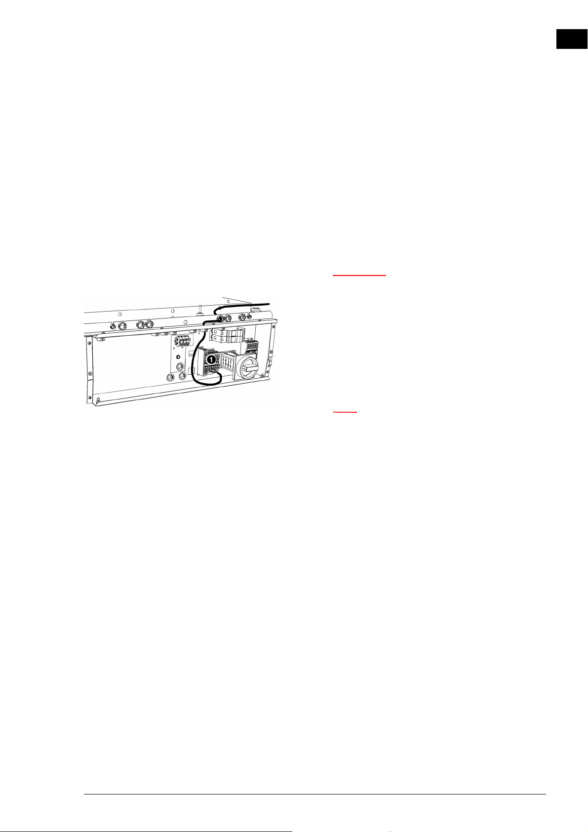
1. Lead the control cable into the unit via the cable gland at
the top of the electronics housing.
en
2. Connect the cable to terminal block X60 1, in accordance with the wiring diagram supplied.
Connecting multiple units with a single controller
n Check in 2.9.1 Special points regarding the
controller to see how many units can be connected
to the controller.
1. Lay the cable between the electronic housings of the units
to be connected
2. Feed the cable into the electronic housings of both units.
3. Connect the cable in both units to terminal block X60 6,
in accordance with the wiring diagram.
4. Repeat steps 1 to 3 for each unit to be connected.
Manual version 6.0 - North America (10-03-2017) en-33
Page 34
en
Note:
Note:
Caution:
Caution:
INSTALLATION AIR HEATER
2.10 Installing the b-touch control panel
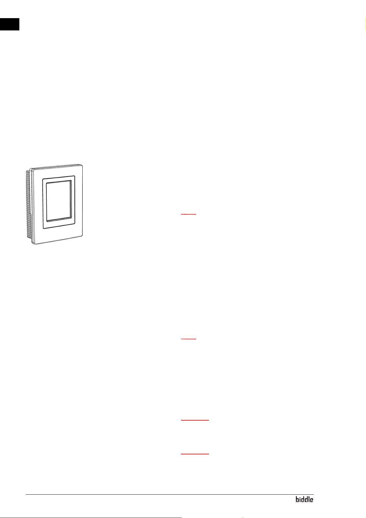
For the NOZ2 air heatervarious control units are available.
This chapter describes the installation of the b-touch control
panel, which is used on units having an automatic control (type
Auto).
2.10.1 Special points regarding the control panel
Positioning
• You can fasten the control panel either to the wall or to a
standard junction box.
Cabling
n Take the following into account, otherwise errors
may occur:
- The control cable between the control panel and the
(first) connected unit may not be longer than 50
m(165 ft.).
- Keep control cables away from electromagnetic fields
and interference sources such as high-voltage cables
and fluorescent light starters, for example.
- Lay the control cables out straight or roll them in a
bifilar coil by folding cables in half before rolling
them. As a result, the magnetic fields will cancel each
other out to an important extent.
n Use Biddle control cables only. Standard modular
telephone cable is NOT suitable.
Multiple units operated from a single control panel
• A maximum of 10 ‘Auto’ units can be connected to a single control panel. And with ‘Auto’ unit, 4 ‘Basic’ units.The
units are thereby daisy chained.
en-34
c Units with differing capacities (type 25 and type 50)
cannot be combined.
c Only with NOZ
with automatic control (Auto) cannot be connected
to units with a basic control (Basic).
V (ventilation) units: Units
2
Page 35
NOZ2 MANUAL INSTALLATION
Note:
Note:
• The total length of the control cables between the first and
the last unit must not exceed 100m (330ft). If the distance
becomes too great, an additional control panel must be
connected.
• Only units from the same product series, with the same
battery type and of the same capacity can be applied in
combination with a single control panel.
• Configure any single unit as the master. The sequence of
the connected units is not important.
• Connect the control panel and the external control components to the master unit.
n The master unit can be recognised by the addition
‘Auto’ on the type designation on the type plate.
en
n Do NOT remove the external control input bridges
on the other units.
Operation without control panel
The unit can be operated without control panel. In that event,
only remove the control panel after complete installation.
Manual version 6.0 - North America (10-03-2017) en-35
Page 36
en
Caution:
Caution:
Caution:
Warning:
INSTALLATION AIR HEATER
2.10.2 Mounting and connecting the control panel
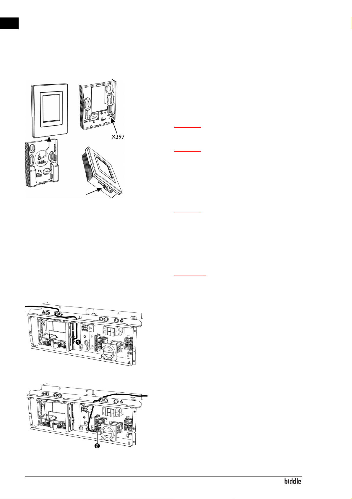
1. Lay the control cable.
2. Slide the control panel out of the wall holder.
3. Connect the control cable to terminal X397.
c Ensure that the wall behind the wall holder is even.
c Place the control panel in the housing supplied if
class IP54 is required. The openings for the cable
guide must be on the bottom.
4. Screw the wall holder onto the junction box or against the
wall.
c The control panel should only be put back into the
wall holder when the power supply of all the
connected units has been switched on.
2.10.3 Connecting the control panel to the unit
w Make sure that the mains supply group with
which you are working has been turned off.
1. Lead the control cable into the unit
2. Connect the cable to terminal block X530 1, in accordance with the wiring diagram.
Connecting multiple units with a single control panel
1. Lay a 2-core cable between the electronic housings of the
units to be connected
en-36
2. Feed the cable into the electronic housings of both units.
3. Connect the cable in both units to terminal block X60 2,
in accordance with the wiring diagram.
4. Repeat all steps for each unit to be connected.
Page 37
NOZ2 MANUAL INSTALLATION
Caution:
Caution:
Note:
Caution:
2.11 Installing external controls
2.11.1 Special points regarding external controls
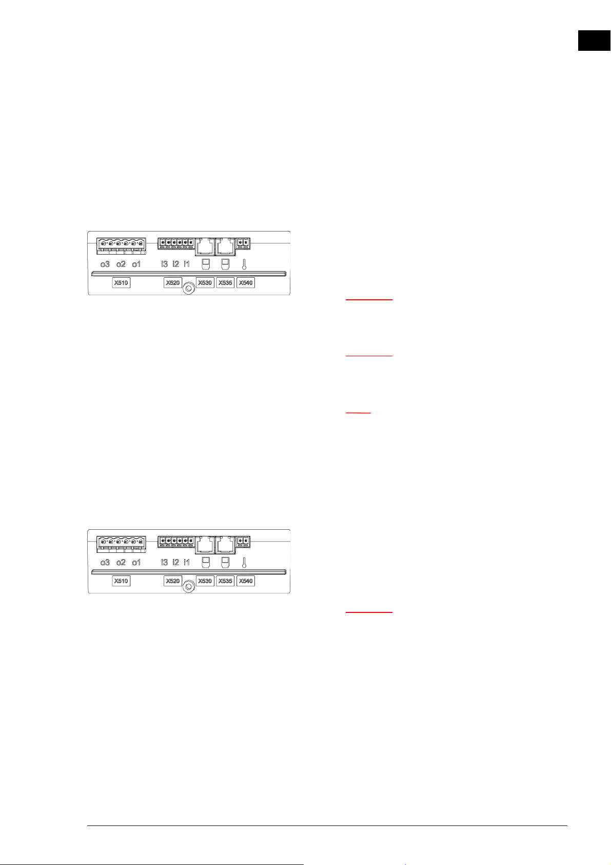
Inputs on the unit i1, i2, i3 (11, 22, 33)
Only for models with automatic CHIPS control
On terminal block X520, the unit has three input signal interfaces. For example, a timer switch or a signal from a building
management system can be connected to this.
c The inputs are designed for controls with potential-
free contacts, and are not to be loaded.
en
c The inputs of multiple units must NOT be connected
to each other.
n With the setting All units off and with the NC
(Normally Closed) settings of function 60. Function
of inputs, a jumper must be laid on the input for all
the subsequent connected units.
Outputs on the unit o1, o2, o3
Only for models with automatic CHIPS control
On terminal block X510, the unit has three signal interfaces
for an output signal. These can be used, for example, for controlling the central heatingor for transmitting status reports to
a BMS.
c The outputs are potential-free contacts (relays).
Their maximum load is 24 V / 1 A.
Options and operation
Options and operation depend on the input or output and on
the control panel settings.
Manual version 6.0 - North America (10-03-2017) en-37
Page 38
en
Caution:
Note:
Note:
Caution:
INSTALLATION AIR HEATER
2.11.2 Installing the room sensor
For models with automatic CHIPS control
The automatic CHIPS control works on the basis of the temperature in the room.
1. Mount the room sensor in the room at a height of approx.
1.5 m.
c Do not place the sensor in the direct airflow path of
the unit.
2. Lay the cable (not supplied) between the room sensor 1
and the unit.
n Use a cable of at least 0.5 mm
2
.
n In an assembly involving several units, connect the
cable to the master unit, which can be recognised by
the addition ‘Auto’ on the type designation on the
type plate.
Take the following into account, otherwise errors may occur:
• Keep the length of the cable as short as possible.
• Keep the cable away from electromagnetic fields and interference sources, such as high-voltage cables and fluorescent light starters, for example.
3. Feed the cable into the unit.
4. Connect the cable to terminal block X540, in accordance
with the wiring diagram.
2.11.3 Connecting the alarm signal
Units with automatic CHIPS control are always equipped with
an alarm signal that gives a message in the event of an error in
the fan.
en-38
Units with a basic control can optionally be equipped with this
alarm signal.
c The contact of a unit which has basic control (Basic
type) may be loaded with a maximum of 250 VAC
and 2 A.
Page 39
NOZ2 MANUAL INSTALLATION
Note:
Note:
Note:
n Contact is made only if the unit is connected to a
power source and there are no errors.
Connecting the alarm signal to the unit
For models with automatic control (Auto type)
The alarm signal can be received via an output, ModBus or
another building management system. Establish the required
connection.
For models with basic control (Basic type)
1. Lay the alarm cable (not supplied) between the unit and
the appliance on which the alarm signal is received.
en
n If the alarm signal is to be connected in series with
several other units: Lay the cable to the unit which is
going to serve as the master.
2. Connect the alarm cable to the appliance on which the
alarm signal must be received.
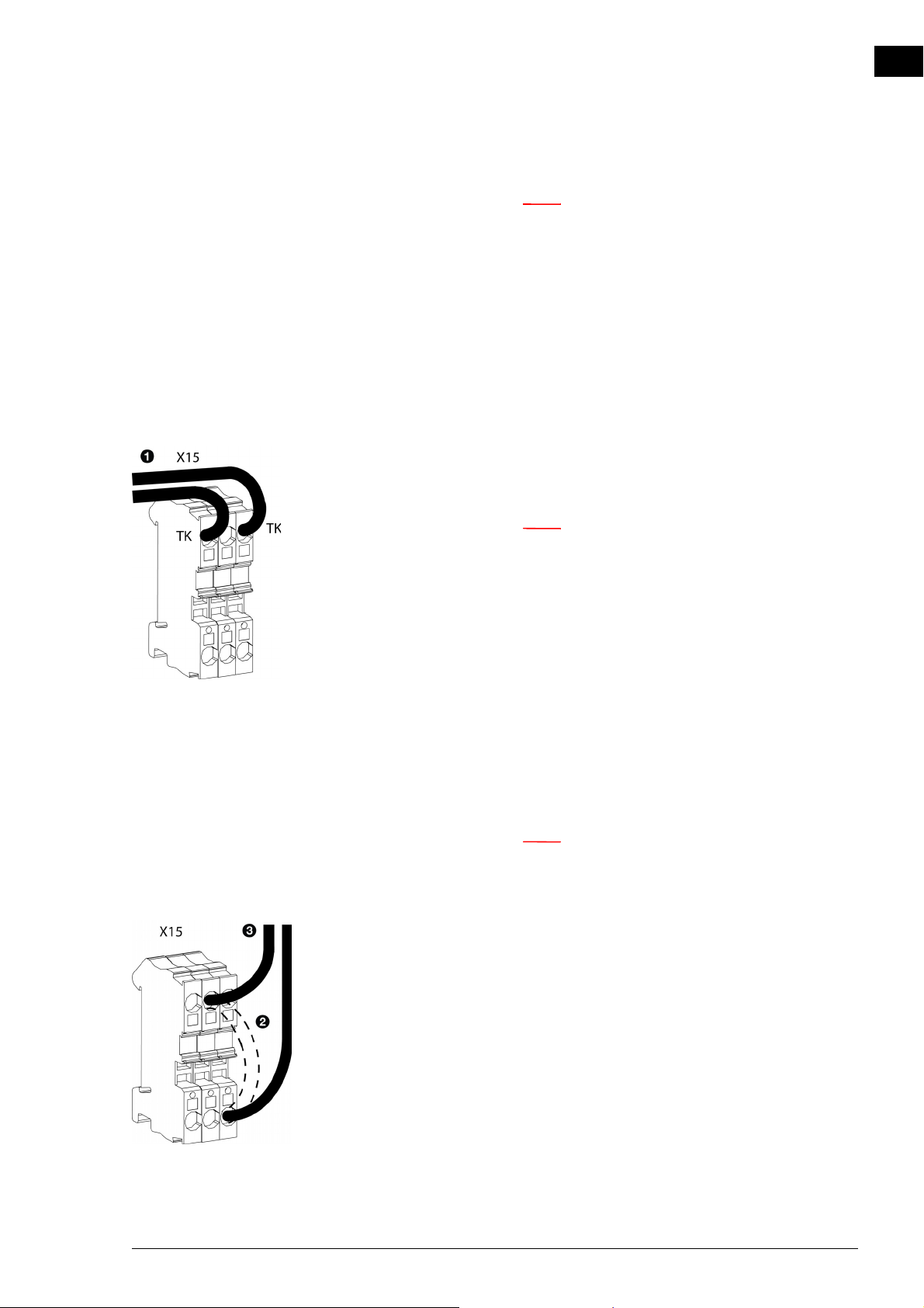
3. Connect the alarm cable in the unit to the TK clamps on
terminal X15 1.
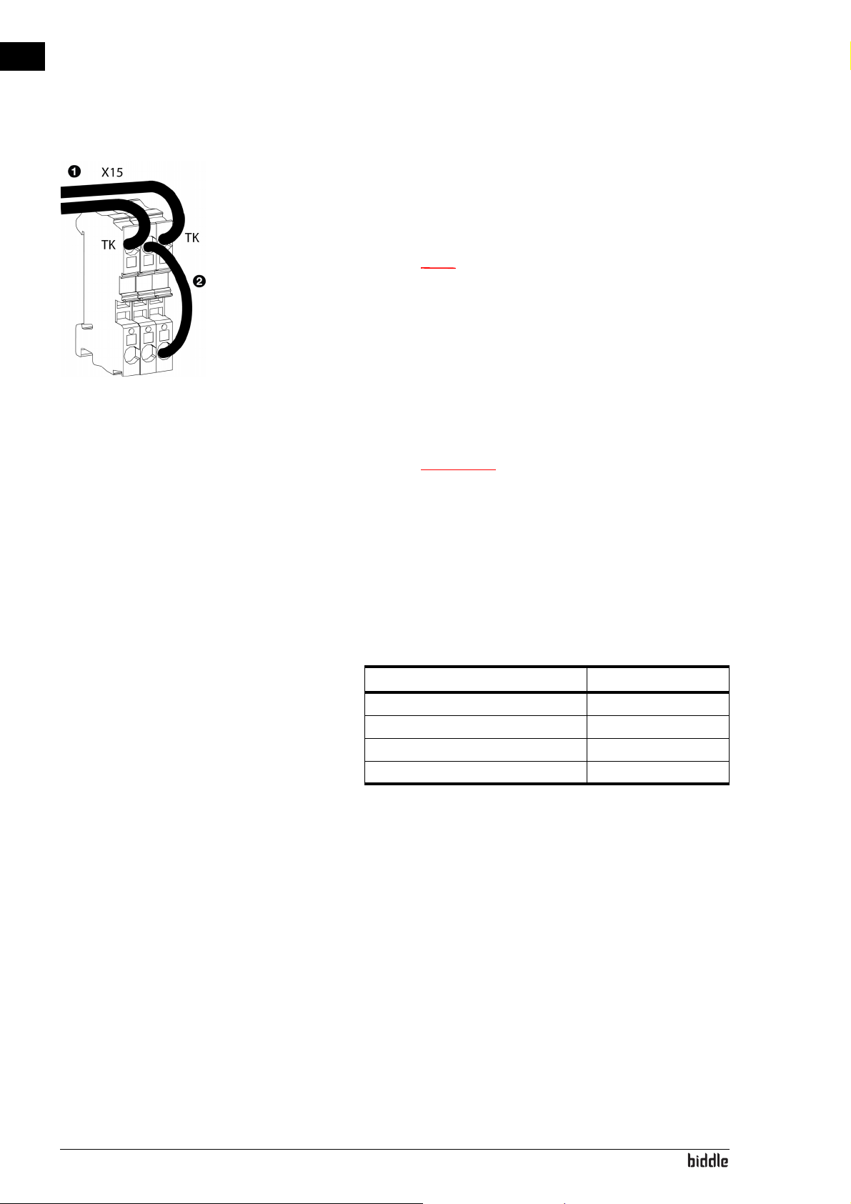
Multiple units with a single alarm signal
In a multiple-unit setup, the alarm signal is connected in series
between the units.
n In a setup consisting only of units having a basic
control (Basic type), each unit can also be connected
independently to an alarm signal.
1. Lay the alarm cable between the units.
2. Connect the alarm cable to terminal X15 on the first unit
to which the alarm signal is already connected (Auto or
Basic master):
- Remove the bridge 2 .
- Connect the cable 3.
Manual version 6.0 - North America (10-03-2017) en-39
Page 40
en
Note:
Opmerking:
INSTALLATION AIR HEATER
3. Connect the alarm cable in the unit which is to be to be
connected in series to the TK clamps on terminal X15 1.
4. Repeat steps 1 to 3 for each unit to be connected in series.
n Leave the bridge in place on the final unit 2.
2.11.4 Connecting the unit to Modbus
n A detailed manual for the connection and usageof
ModBus (and possibly BACnet) is available at:
www.biddle.info.
Communication parameters
The Modbus system must comply with the following communication parameters:
COMMUNICATION PARAMETER VALUE
Baud rate 9600
DATA 8
Parity none
Stop bits 1
The turnaround time between the unit and Modbus is 4.2
msec.
Wiring
en-40
A twisted-pair cable must be used for connection to the Modbus system. The cable must also have a third core for the
GND (grounding). Normally, a four-pole, twisted-pair cable is
used; one pair is used for communication and one core from
the other pair is used as the GND.
Page 41
NOZ2 MANUAL INSTALLATION
Note:
Note:
Note:
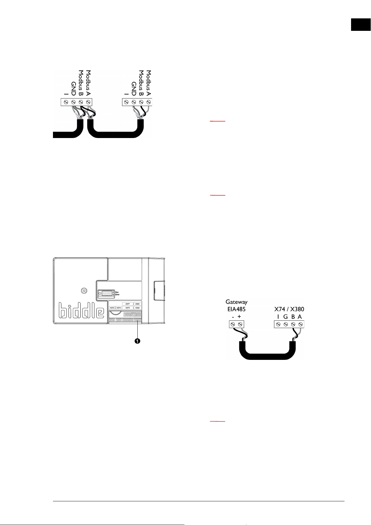
Modbus A = -
Modbus B = +
GND = ground
n If there is no communication, this may be caused by
incorrectly connected wiring. Swap the A- and B+
wires.
Connecting the unit to Modbus
1. Lay a cable between the Modbus system and the unit.
n In an assembly involving several units, connect the
cable to the master unit, which can be recognised by
the addition ‘Auto’ on the type designation on the
type plate.
en
In the case of BACnet: Lay the cable between the gate-
way and the unit.
2. Attach the cable to the unit, in accordance with the wiring
diagram supplied:
In the case of BACnet: Use the circuit diagram below.
- Feed the cable into the electronic housing.
- Connect the cable to terminal X380 1 of the unit’s
control circuit board.
n For a more reliable signal, it is possible to connect a
120 Ohm resistor. For this purpose, place a bridge
between positions 1 and B of terminal X382 on the
control circuit board in the unit.
Manual version 6.0 - North America (10-03-2017) en-41
Page 42
en
Note:
Caution:
INSTALLATION AIR HEATER
n The b-touch control panel is no longer necessary for
purposes of operation. After you have gone through
the installation guide, it can be removed. However,
do keep it, so as to be able to adjust settings at a
later stage.
2.12 Unit finishing
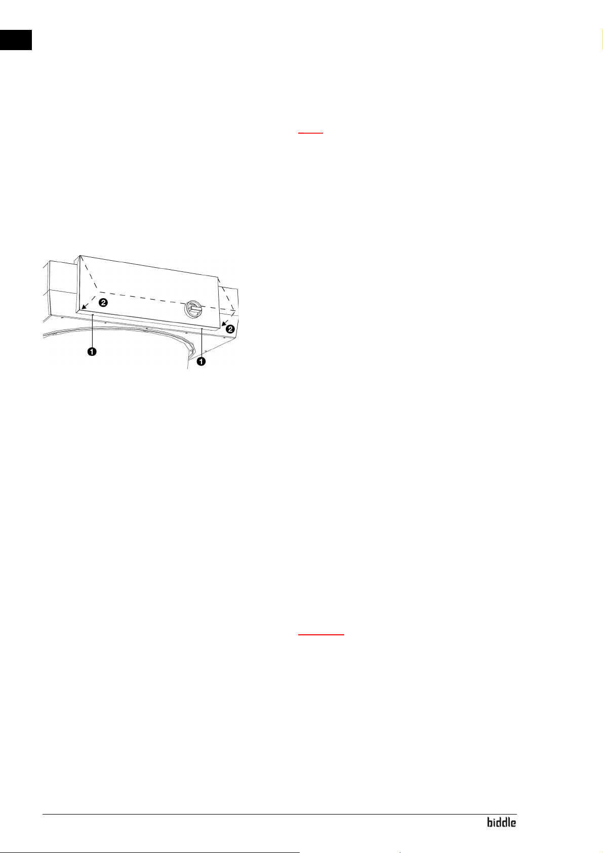
1. Close the electronics housing: replace the cover2 and fasten the screws 1 at the bottom of the housing.
2.13 Switching ON and checking operation
For all models:
1. Check the following connections:
- power supply;
- control cable(s) between control panel and unit(s);
- If applicable:
external control components.
For all models:
1. Switch the mains supply on.
c Make sure that the unit’s power supply voltage
matches the local mains voltage.
The unit’s power supply voltage is displayed on the
type plate.
en-42
2. Set the isolation switch to 1. (if applicable: on all units)
Page 43
NOZ2 MANUAL INSTALLATION
Note:
Note:
For models with b-control continuously variable controller
1. If so desired, adjust the output voltage of the controller:
1. Remove the adjustment button.
2. Remove the hexagonal nut.
3. Remove the shut-off cap.
4. Attach a multimeter to ‘Vout’.
5. Set the switch to the minimum voltage:
- Turn the switch all the way to the left;
- Turn it to the right until the switch clicks;
- Carefully turn it to the left until you feel resistance, but
the switch does not quite click.
- Set the desired minimum voltage, using a screwdriver.
en
n Set the minimum voltage to at least 2V.
6. Turn the switch all the way to the right.
7. Set the desired maximum voltage, using a screwdriver.
n The set max. voltage must be greater than the set
min. voltage.
8. Fit the shut-off cap.
9. Fasten the hexagonal nut.
10. Fit the adjustment button: Press this on firmly and set
to position ‘0’.
2. Turn the unit on, using the controller.
Manual version 6.0 - North America (10-03-2017) en-43
Page 44
en
Caution:
Note:
Note:
INSTALLATION AIR HEATER
For models with b-touch control panel
1. Place the control panel back into the wall holder.
When you connect the control panel, the control panel
searches for connected units and then briefly displays the
number of connected units.
c If the number of units displayed does not match the
number connected, check the wiring and power
supply of the units and reconfigure the system via
menu > Maintenance > Reset system.
Optional:
Lock the control panel with the screw on the
underside.
During the first start-up, the installation guide is initiated.
Go through this in order to make the most necessary settings.
If the installation guide is not displayed, it can be started via
menu > Maintenance > Installation.
If the control panel does not work, or if the display shows
an error message, there is an error: consult the relevant
section.
n The settings of the b-touch control panel can be
copied to another b-touch control panel. See
7.9 Copying the settings.
n After installation, the control panel may possibly be
removed. See 2.10.1 Special points regarding the
control panel for the conditions.
For all models:
en-44
1. Check whether the fans are rotating.
Page 45
NOZ2 MANUAL INSTALLATION
Caution:
Caution:
For water-heated models (type H):
1. Check whether the heat exchanger is connected correctly.
2. Make sure that the central heating system has been turned
on.
3. If the b-touch control panel is implemented: Make sure that
the heating is enabled on the control panel.
4. Feel whether the discharged air stream becomes warm.
This may take some time and is dependent on the need for
heating.
5. Vent the heat exchanger.
6. Adjust the unit on the water side:
en
c For models with basic control (type Basic) without
application of water-side control: Ensure that at the
lowest fan speed the maximum discharge
temperature is not exceeded. For the maximum
discharge temperature, see section 1.3.5 Field of
application.
c In the case of a combination of models with a control
circuit board (type Auto) and models without control
circuit board (Basic): Adjust all units on the water side.
Ensure that all units have the same discharge
temperature.
Manual version 6.0 - North America (10-03-2017) en-45
Page 46
en
Note:
3. . Operation with b-control
Various control units are available for the NOZ2 air heater.
This chapter describes operation with the b-control continuously variable controller that is used on units having a basic
control (Basic type).
3.1 Introduction
This section describes the functions of the b-control continuously variable controller which are necessary for the operation of the unit. The isolation switch on the unit is only
needed during maintenance and servicing.
3.2 Switching ON and OFF
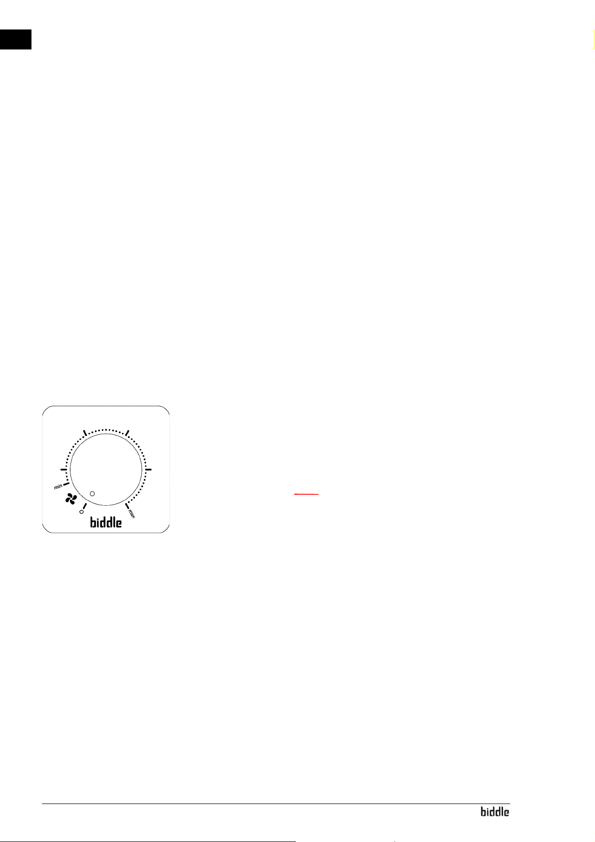
3.3 Regulating the strength
When the controller is set to strength 0, the unit is switched
OFF.
Turn the knob of the controller clockwise in order to switch
the unit ON.
n The unit switches on commencing at the minimum
strength 'min'.
The fan speed can be regulated in a continuously variable manner with the controller.
The most optimal speed is the minimum strength at which the
airflow touches the ground and there is no draught across the
ground. This may vary per day and during the course of the
day.
en-46
Page 47
4. . Operation with b-touch
Note:
Various control units are available for the NOZ2 air heater.
This chapter describes operation with the b-touch control
panel, that is used on units having an automatic control (Auto
type).
4.1 Introduction
This section describes the functions of the b-touch control
panel, which are required for setting up the unit.
en
n After installation, the control panel may possibly be
removed. See 2.10.1 Special points regarding the
control panel for the conditions.
For the purpose of altering setting easily, the control panel can remain present.
The illustrations show screens for a unit with ventilation. For
units without ventilation, the parts relating to ventilation are
not visible.
Manual version 6.0 - North America (10-03-2017) en-47
Page 48
en
OPERATION WITH B-TOUCH AIR HEATER
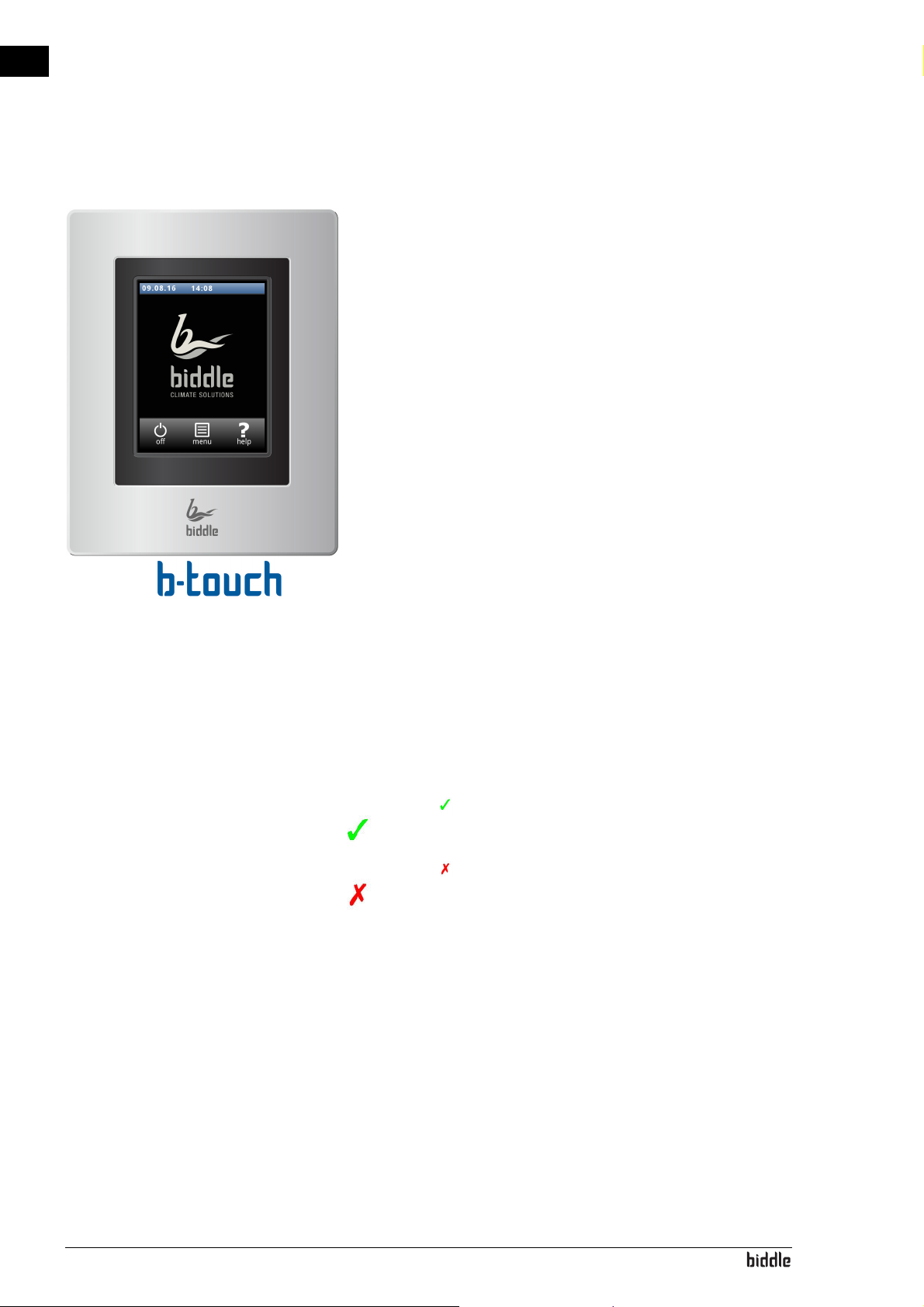
4.1.1 Control panel
The b-touch control panel is equipped with a touch screen
(touch screen) with which all the functions can be set:
• Turning the unit ON and OFF;
• Adjusting the strength of the unit;
• Switching the heating ON and OFF;
• Entering settings to adjust the operation of the unit to
your situation.
4.1.2 Multiple units operated from a single control
panel
If multiple units are connected to the b-touch control panel,
the settings on the panel are the same for all units.
4.1.3 Settings
Select to save the settings and return to the previous
screen.
Select to return to the previous screen without saving the
changes.
en-48
Page 49
NOZ2 MANUAL OPERATION WITH B-TOUCH
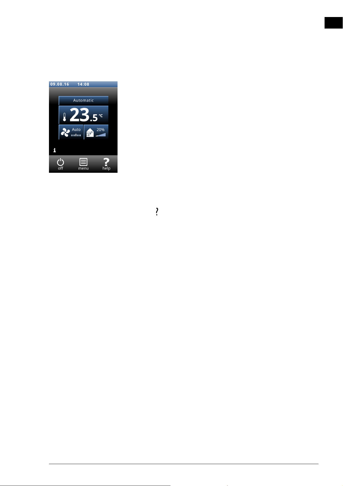
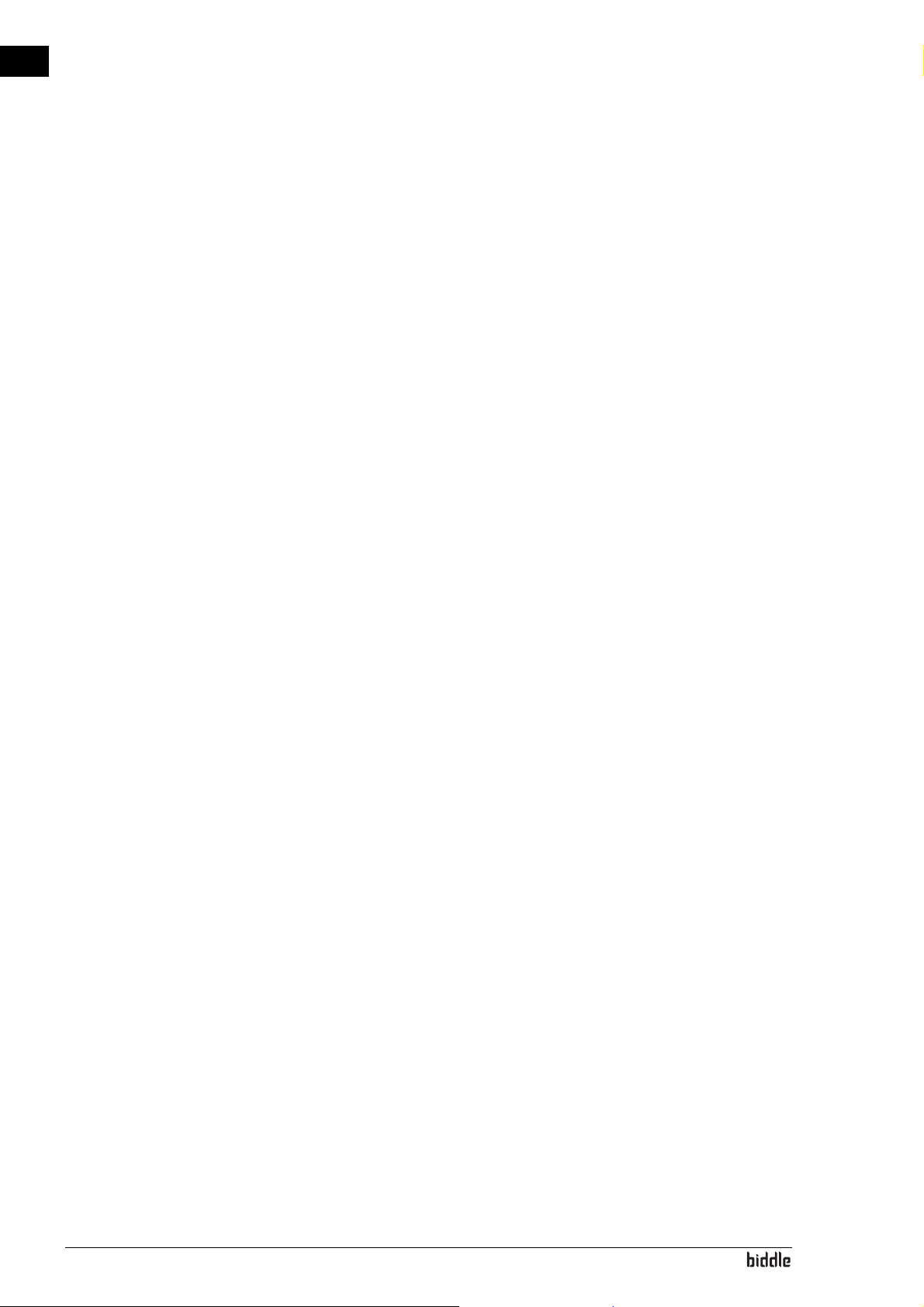
4.2 The Home screen
The settings of the unit and the room temperature can be
adjusted on the Home screen.
• Touch the parts of the symbol to select manual or automatic and to adjust the strength of the unit or the room
temperature.
• With fan units, touch the part of the symbol to adjust the
ventilation percentage.
• Touch the ‘i’ to obtain concise information about the operation of the unit.
•Touch menu to open the main menu.
4.2.1 Help function
en
At any time, you can call up additional information concerning
the point in the operation where you are, by touching Help.
4.2.2 Turning the unit ON and OFF
You can switch the unit ON and OFF manually, using the control panel.
•Touch on/off in order to turn the unit ON or OFF.
If the unit is on, the screen will become darker after some
time, in order to save energy. When the screen is touched, it
lights up again. This function cannot be deactivated.
If the unit is switched off, the screen will go black after some
time. Touch the screen to activate it again.
The unit can also be switched ON and OFF in other ways:
• Using external controls (see function 65. Control panel
input and 60. Function of inputs).
• Via the internal timer or via an external release signal on
the unit.
In these cases, the ON/OFF button can be hidden via Con-
figuration > 21. User interface options > Display on/off
button.
Manual version 6.0 - North America (10-03-2017) en-49
Page 50
en
OPERATION WITH B-TOUCH AIR HEATER
4.2.3 The CHIPS control
By default, the unit operates with fully automatic control.
Depending on the selected settings, the unit can also be controlled manually. In automatic mode, the unit operates under
CHIPS control. This control matches the strength and heat of
the unit to changing weather conditions. This reduces energy
consumption and improves comfort through selection of the
optimum setting under all circumstances. CHIPS stands for
“Corrective Heat and Impulse Prediction System”.The unit
works on the basis of the room temperature and the temperature of the discharged air near the unit.
4.2.4 Automatic or manual control
The unit has an automatic mode and a manual mode. You can
select these by touching the uppermost part of the symbol.
When the unit is switched on, it is always in automatic mode.
If you wish to use the unit in manual mode only, switch off the
automatic mode via menu > Settings > 1. Select modes.
In the manual mode, the unit operates with a fixed set fan
speed, possibly influenced by the settings of function 26. Man-
ual: Door response.
Recommended setting of the unit
To obtain the greatest possible comfort with the least possible energy consumption, Biddle recommends use of the fully
automatic CHIPS control.
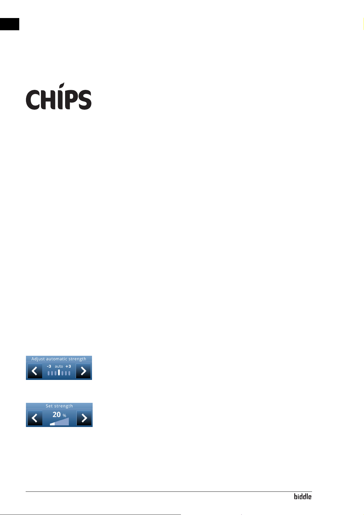
4.2.5 Regulating the strength
Adjusting the automatic strength control
In automatic mode, the strength and temperature of the airflow are regulated automatically. in certain circumstances you
might want to adjust the automatic setting.
Manual setting of the strength
With the manual setting, you can select the strength. To
achieve maximum comfort with minimum energy consumption, Biddle recommends selecting the lowest strength at
which the airflow touches the ground. This setting may possibly need to be changed during the course of the day.
en-50
Page 51
NOZ2 MANUAL OPERATION WITH B-TOUCH
Warning:
Note:
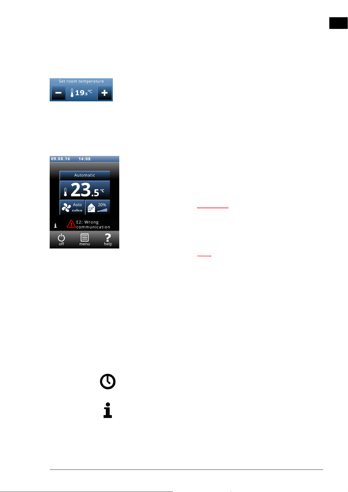
4.2.6 Required room temperature
You can set the temperature to a comfortable level. This is the
temperature near the room sensor.
Temperature adjustments made via the home screen of the b-
touch control panel only apply until the starting time of the following period. The default value can be set via
menu > Settings > 5. Room temperature.
4.2.7 Errors
The symbol ä indicates that there is an error. The error message is also displayed alongside.
• Touch this message for further information on the error
and for instructions as to how to react.
en
w Some errors may cause damage or danger to
persons if they are disregarded. If ä is
displayed, follow the instructions on the
control panel concerning how to act.
n The symbol ä and the error message remain
displayed as long as the error has not been
remedied.
If an error has remedied itself, a corresponding message will
be displayed. Touch this message to display the Error history
and to read out the errors and the times of their occurrence.
This list can also be read out via Maintenance > Error history.
See also:
5.2 "Error messages on the control panel" on page 66
4.2.8 Symbols
The symbol
@ indicates that the timer is switched on.
The symbol ‘i’ indicates that there is currently a tip to be read.
Touch the symbol in order to read the tip.
Manual version 6.0 - North America (10-03-2017) en-51
Page 52
en
OPERATION WITH B-TOUCH AIR HEATER
4.3 Main menu
To u c h menu in order to open the Main menu. Here you can
enter settings for a number of frequently used functions; in
submenus you can enter settings in order to adapt the operation of the unit to your specific situation.
•Touch home in order to return to the Home screen.
• Using v and x you can browse through the list.
If the control panel is not operated for some time, it returns
automatically to the Home screen without saving the changes.
Lock screen Select Lock screen in order to prevent unauthorised access.
The
# symbol appears on the screen.
Unlocking
Touch the screen for 5 seconds to unlock it.
Turning the heating on and off The unit’s heating can be switched on and off manually.
Switching the heating off disables the room temperature control and any Heating on output functions.
This function can be deactivated via setting 21 in the configuration menu.
•Select Heating.
The heating can also be switched off by the control itself:
• by an external signal on the unit’s input, see
menu > Configuration > 60. Function of inputs, setting
Heating off;
• when the room temperature is higher than the setting of
function 41. Heating OFF temperature.
Cleaning display Using the touch screen can leave marks or fingerprints on the
screen. The screen can be cleaned using a damp, soft cloth.
en-52
Use this function to disable the touch screen for 20 seconds in
order to be able to clean it.
Page 53
NOZ2 MANUAL OPERATION WITH B-TOUCH
Timer The b-touch control panel has a week timer. You can set two
start and stop times for each day of the week. The unit is on
between the start time and the stop time. The second start
and stop times are optional. When the ON/OFF button is displayed on the screen, the unit can also be switched ON or
OFF manually. From the next switching moment, the unit follows the timer again. When the timer is switched on, the symbol
@ is displayed on the Home screen.
4.4 Preferences
Preferences The menu Preferences allows you to make settings for the use
of the control panel.
en
Set language The control panel offers a choice of languages. Choose your
preferred language from the list.
Set date and time The date and time are necessary for the timer function and for
tracking usage statistics of the unit.
The automatic summer time function switches the clock to
summer or winter time in accordance with the applicable
European rules. If you do not use this function, you can switch
to summer time manually. The clock is then set one hour forward.
Celsius / Fahrenheit Choose between a temperature display in degrees Celsius or
degrees Fahrenheit.
Display brightness Set the brightness of the screen to your personal preferences
or to the specific situation.
Show tips The control panel can show tips about the usage of the unit.
The display of these tips can be enabled or disabled.
Manual version 6.0 - North America (10-03-2017) en-53
Page 54
en
Note:
Warning:
OPERATION WITH B-TOUCH AIR HEATER
4.5 Settings
The Settings menu allows you to enter settings which influence the day-to-day use of the unit.
1. Select modes The control panel has an automatic mode and a manual mode.
With the function Select modes, you can set which of these
modes can be selected in the HOME screen.
5. Room temperature Here, set the temperature which is to be used by default as
the room temperature when starting up the unit.
The desired room temperature can temporarily be adjusted
on the home screen until the next start-up moment.
6. Minimum air temperature Set the minimum difference between the room temperature
and the discharge temperature.
This difference can be increased for more comfort. A smaller
difference saves energy.
8. Night temperature The night temperature is used when the unit is switched off.
When the room temperature drops below this set value, the
unit will start working in order to keep the room at the night
temperature.
n This function only operates when the heating is
switched on.
w Be aware that the airflow of the unit can set
objects in motion. This might set off an alarm
system in the building at night time.
9. Calibration An unfavourable positioning of the room sensor or use of the
temperature sensor in the unit may be the reason why the displayed temperature deviates from the actual temperature.
en-54
Use this function to adjust the temperature reading.
Page 55
NOZ2 MANUAL OPERATION WITH B-TOUCH
4.6 Configuration
The menu Configuration allows you to enter settings in order
to adjust the operation of the unit to the room and the system. Usually, this menu is used only for installation, maintenance and service purposes.
20. Access control Pin code
Access to the entire control panel or to the menu only can be
protected with a four-digit PIN code.
The default PIN code is 0000.
Access level
The control panel can be safeguarded at different access levels.
en
21. User interface options Display on/off button
The unit can be switched ON and OFF manually. This can also
be done via the internal timer or via an external release signal
on the unit. In this case you can disable the manual on/off
option. The on/off button is then not displayed on the Home
screen.
Temperature display
By default, the room temperature is displayed. With this function, you can select another temperature to display or switch
off the temperature display.
If the temperature display is switched off, there is no temperature control.
Heating OFF option
Use this function to enable or disable the option which allows
the user to switch the heating ON/OFF manually.
Error display
Some error messages may be caused by external factors such
as the central heating system and do not necessarily have an
influence on the functioning of the unit.
Use this function to suppress these messages. Safety-related
warnings will always be displayed.
Manual version 6.0 - North America (10-03-2017) en-55
Page 56
en
OPERATION WITH B-TOUCH AIR HEATER
31. Maximum strength In order to restrict the sound level, the maximum fan speed
can be limited. This function only has effect on the automatic
mode.
Use of this function can reduce comfort.
32. Deceleration time You can set a post-rotation time for the fan. Here, set the
period of time it should take for the fan to decelerate from
maximum speed to standstill.
33. Boost function If there is a great difference between the desired room tem-
perature and the actual room temperature, the fan speed can
be increased in order to reach the desired temperature more
quickly.
Set the temperature difference at which the boost function
should be activated and what the fan’s increase in speed should
be.
35. Ventilation settings Only for models with ventilation
Ventilation control
The relationship between ventilation air and recirculated air
can be determined in various ways:
• Manual selection: Manual switching between ventilation and
recirculation.
• Valve regulation: Manual regulation of the position of the
ventilation valve.
Maximum position of ventilation valve
The maximum opening percentage of the ventilation valve can
be limited.
Minimum fan speed during ventilation
Set the minimum percentage of the fan speed for ventilation.
Maximum fan speed during ventilation
Set the maximum percentage of the fan speed for ventilation.
en-56
Page 57
NOZ2 MANUAL OPERATION WITH B-TOUCH
Note:
Note:
Note:
46. Maximum discharge temperature The controller limits the discharge temperature to a maxi-
mum of 50°C. Possibly set a lower value in order to save
energy.
47. Overheat protection If the actual room temperature becomes higher than the pre-
set room temperature, the heating can be switched off in
order to prevent the room from becoming too warm.
Set the temperature above which the heating must be disabled.
n This function can only be used if the unit is set to
automatic.
n If this function is activated, then function 6. Minimum
air temperature is ignored.
en
50. Installation height In order to use the automatic control as efficiently as possible
and with minimum energy consumption, it is necessary to set
the installation height of the unit correctly.
n Use values in metres.
The installation height is the distance from the floor to the
underside of the unit.
52. Nozzle angle For optimal operation of the unit, the nozzles must be set at
the correct angle. Section 2.6 Regulating the discharge direc-
tion describes how the correct nozzle angle is determined.
In order to use the automatic control as efficiently as possible
and with minimum energy consumption, it is necessary to set
the nozzle angle in the control panel.
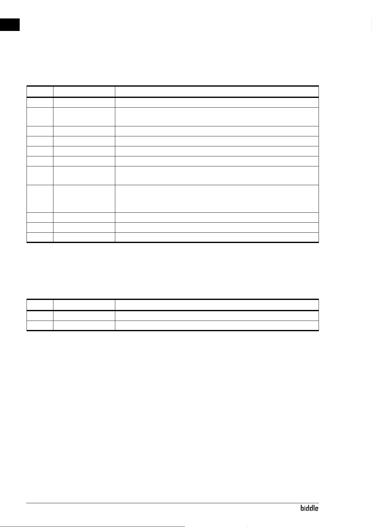
60. Function of inputs The unit has three inputs (terminal block X520) which can be
used to enable a function to be controlled by an external
accessory such as a thermostat or a signal from a building
management system.
Manual version 6.0 - North America (10-03-2017) en-57
Page 58
en
OPERATION WITH B-TOUCH AIR HEATER
Values for inputs 1 and 2
V
ALUE OPTION DESCRIPTION
0 No function The input has no function.
1 Unit off locally – NO The unit is switched OFF when the contact is closed. (This only works with
the units to which the input signal is directly connected (locally).)
6 Heating off The heating is switched OFF when the contact is closed.
9 Release – NO The user is allowed to switch the unit on and off when the contact is closed.
10 Dirty filter – NO Displays a “dirty filter” warning if the contact is closed.
21 Switch all units on All units are switched ON when the contact is closed.
51 Unit off locally – NC The unit is switched OFF when the contact is open. (This only works with the
units to which the input signal is directly connected (locally).)
56 Heating on
(dependent on software version)
59 Release – NC The user is allowed to switch the unit on and off when the contact is open.
60 Dirty filter – NC Displays a “dirty filter” warning if the contact is open.
71 All units off All units are switched OFF when the contact is closed.
The heating is switched ON when the contact is closed.
The function of input 3 is set via other functions in the b-touch
control panel. In addition, the function of this parameter (60.3)
is controlled via the settings file or via Modbus.
Values for input 3
VALUE OPTION DESCRIPTION
21 Switch all units on All units are switched ON when the contact is closed.
71 All units off All units are switched OFF when the contact is closed.
Release delay input 1
When you use input 1, you can make the effect of an input signal persist for some time after the signal has been given
(‘release delay’).
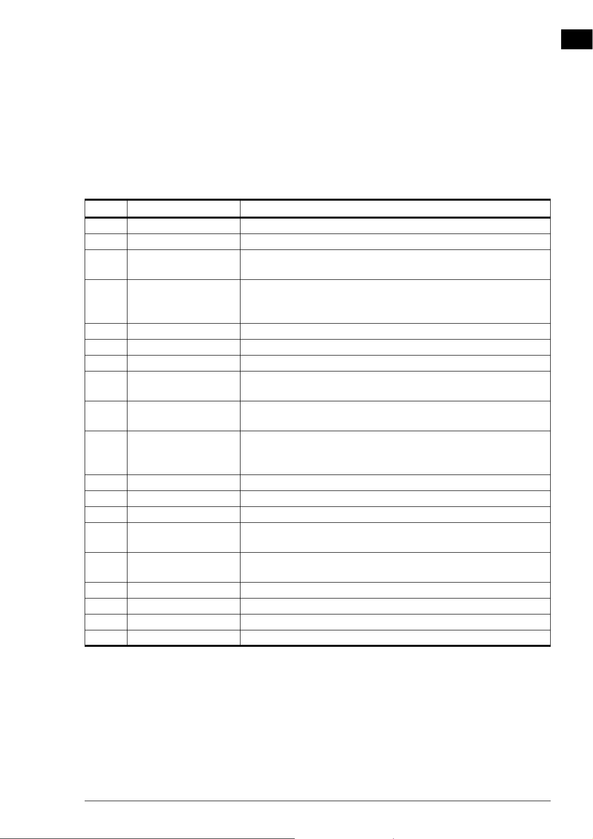
61. Function of outputs The unit has a connection (terminal block X510) for three
output signals: these can be used for controlling the central
heating system, for example, or for transmitting status
reports to a Building Management System (BMS).
en-58
By default, output 3 is used for error messages.
The outputs work independently of each other.
Page 59
NOZ2 MANUAL OPERATION WITH B-TOUCH
Multiple units operated from a single control panel.
The outputs always have a global effect: the signals are always
the same in all units connected to the control panel.
Value s
V
ALUE OPTION DESCRIPTION
1 Error – NO The contact is closed as soon as an error occurs.
2 Dirty filter – NO The contact is closed as soon as the maximum filter lifespan has expired.
3 Heating deficit The contact is closed when the unit cannot reach the desired air tempera-
ture.
4 Error or dirty filter –
NO
The contact is closed as soon as an error occurs or when the maximum filter lifespan has expired.
(if filter present)
8 Unit on The contact is closed as soon as the unit is switched on.
10 Error local – NO The contact is closed as soon as an error occurs in the unit in question.
11 Fan active – NO The contact is closed when the fans are running.
13 Heating on The contact is closed when the unit requires heating. Use this to switch
the heating system ON or OFF via the unit.
15 Risk of freezing The contact is closed when the temperature inside the unit drops below 7
°C.
17 Use boost function The contact is closed when the difference between the desired tempera-
ture and the room temperature is greater than the value set for 33. Boost
function.
31 Copy input 1 The output follows the contact on input 1
32 Copy input 2 The output follows the contact on input 2
33 Copy input 3 The output follows the contact on input 3
40 Overheating protection The contact is opened as soon as the high-limit thermostat has been acti-
vated (only for output 3, only for models with electrical heating)
41 Fan malfunction – NC The contact is opened when there is a malfunction in the fan. (only for
output 3, only for types L and XL)
51 Error – NC The contact is opened as soon as an error occurs.
52 Dirty filter – NC The contact is opened as soon as the maximum filter lifespan has expired.
60 Error local – NC The contact is opened as soon as an error occurs in the unit in question.
61 Fan active – NC The contact is opened when the fans are running.
en
71. Indoor temperature sensor Select the sensor which the system must use for the indoor
temperature:
It is possible to limit the room temperature that can be set by
the user. Set a minimum and a maximum room temperature.
Manual version 6.0 - North America (10-03-2017) en-59
Page 60
en
Note:
OPERATION WITH B-TOUCH AIR HEATER
4.7 Maintenance
The menu Maintenance contains information on the use of the
unit and offers a number of functions which are necessary for
remedying errors.
Status The status screen displays general information about the
installation and specific information per group and per unit
connected.
Current errors Gives an overview of current errors. The error messages can
also be deleted here.
Error history Gives an overview of the errors which have occurred.
Capacity test Use this function to test the capacity of the unit and your
heating installation.
The unit will run for 120 minutes at the highest fan speed and
with the highest heating capacity. You can check the discharge
temperature and the heating capacity per metre of unit length.
The discharge temperature is limited to 50°C.
For units with water heating:
if the heating capacity is too low, check the supply and return
water temperatures and the water flow.
Valve check Use this function to check the operation of the water valve:
1. Set the opening percentage of the valve to 0%;
2. Press start. The fans will start rotating at the highest speed;
3. Check whether the discharged air is cold;
n It may take some time before the valve reaches the
adjusted opening percentage.
en-60
4. Repeat steps 1 and 2 for the percentages 50% and 100% as
well. In doing so, check whether the discharged air gets
warmer per step.
Page 61
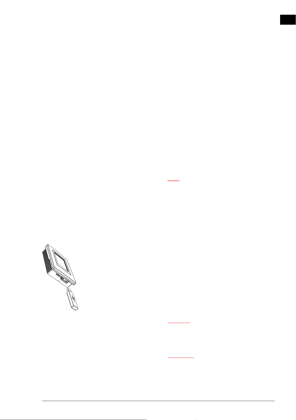
NOZ2 MANUAL OPERATION WITH B-TOUCH
Note:
Caution:
Warning:
Installation This installation guide leads you through the most frequently
required settings.
The installation guide is started up automatically during the
first start-up of the unit or after the resetting of the factory
configuration.
Unit code For entering the unit code after replacement of the control
circuit board in a unit.
Default settings Restores the default factory settings of the setup menu. The
settings entered in the configuration menu are retained.
Factory configuration Restores the standard factory configuration. All settings are
then lost.
en
n The installation guide will be restarted.
Reset system The control panel searches for connection with the attached
units again. Use this function when remedying errors and during connection or disconnection of units.
4.8 USB
The control panel is equipped with a USB port to which only a
USB flash drive can be connected. This is used for:
• updating the software
• importing and exporting settings
• exporting usage data
This menu is automatically activated when a USB flash drive is
connected. The menu is closed again when the USB flash drive
is removed.
c Do not remove the USB flash drive during the
updating or during the importing or exporting of
data. This can take several minutes.
w Connection of other electronic devices to the
USB port can cause serious damage to the
control panel or to other electronic
components.
Manual version 6.0 - North America (10-03-2017) en-61
Page 62
en
Note:
OPERATION WITH B-TOUCH AIR HEATER
Software update Biddle is working continuously on improving its products and
recommends that you update the software of the control
panel when updates become available. Consult www.biddle.info/software to see if updates are available.
• The installed version of the software can be read out from
Maintenance > Status.
• Download the latest version of the software via Biddle’s
website.
See also: 7.10 Updating the software
Upload logo It is possible to use your own logo or image as background for
the display.
Requirements for the image:
• Windows bitmap;
• Filename: logo.bmp;
• Dimensions: maximum 240 x 320 pixels;
• Colour depth: 8-bit grayscale or 24-bit colour.
n Uploading your own logo replaces the standard
Biddle logo.
Export/import settings For copying settings between control panels.
See also: 7.9 Copying the settings
Exporting system info Export the file ‘system_info’ for an overview of all connection
control circuit boards and control panels with corresponding
software versions.
en-62
Page 63
NOZ2 MANUAL OPERATION WITH B-TOUCH
Note:
Export log... The Export log functions write data concerning the operation
of the unit to the USB flash drive. These files can then be analysed on a computer.
The files contain the following data:
• log_func: Data concerning the operation of the unit.
• log_error: Error report history.
• log_user: User settings history.
• log_stat: not in use.
• system_info: Overview of connected control circuit boards
and control panels.
n The process of exporting can take several minutes.
Repeat if 100% is not achieved.
en
Manual version 6.0 - North America (10-03-2017) en-63
Page 64
en
Danger:
Warning:
5. . Errors
d All work on the inside of the unit may only be
carried out by personnel who are technically
qualified to do so.
w Before you begin: read the safety instructions.
See also:
1.5.2 "Safety issues relating to installation, maintenance and servicing" on page 12
5.1 Resolving simple problems
If you suspect an error, first try to resolve the problem, using
the table below. You do not have to be an expert in order to
do this.
If this fails to resolve the problem, there may be a fault; in that
case, alert the installer.
Some problems can be resolved simply by resetting the system once. (see5.2.3 Error messages on the control panel-
Reset system)
P
ROBLEM PROBABLE CAUSE WHAT TO DO
The unit does not work. The unit has not been switched on Switch the unit on
The unit has no power supply. Check the mains supply:
•isolation switch,
The unit has been switched off by
external control components
Check external control components, if present:
en-64
Page 65
NOZ2 MANUAL ERRORS
P
ROBLEM PROBABLE CAUSE WHAT TO DO
The unit is not discharging much air. The nozzles are not working opti-
mally.
The unit is set at too low a
strength.
Only for models with heating: The
heat exchanger has become dirty.
The unit is not heating or not heating sufficiently.
For units which have automatic regulation and b-touch control panel:
The control panel display is black. The control unit has no power sup-
The display is on, but does not
react to touch.
The display flickers The power supply is too low or not
The unit discharges cold air . The heating has been switched off
The unit is set at too low a
strength.
Only for water-heated models: The
central heating system is not working properly.
ply.
If the
# symbol is shown on the dis-
play: The display is locked.
constant
manually.
The (set) room temperature has
been reached. The unit is ventilating
unheated.
The heating has been switched off
by a signal to the unit’s input.
Check the nozzles:
• Are the openings free of obstacles?
• Is the unit hanging at the correct height?
• Are the nozzles adjusted to the
correct angle?
Switch the unit to a higher strength.
Clean the heat exchanger.
Switch the unit to a higher strength.
Check the central heating system.
• Check the connections.
• Check the operation.
• Check the capacity.
Check the mains supply:
• plug in the power socket,
• isolation switch,
Touch the screen for 5 seconds to
unlock it.
Reduce the brightness of the display
to a level at which flickering no
longer occurs, via
menu > Preferences > Display
brightness.
Turn the heating on via
menu > Heating.
This is not an error.
This is not an error. If this is considered a problem, the function of the
input can be changed via 60. Func-
tion of inputs.
en
Manual version 6.0 - North America (10-03-2017) en-65
Page 66
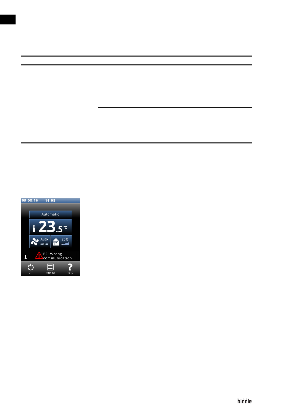
en
ERRORS AIR HEATER
P
ROBLEM PROBABLE CAUSE WHAT TO DO
The unit is discharging air harder
than expected
If there is a big difference between
the set temperature and the actual
temperature, a unit may temporarily operate at a higher setting in
order to attain the pre-set temperature faster.
The nozzles are not working optimally.
This is not an error. If this is considered a problem, you can switch off
function 33. Boost function or set it
to a different temperature difference or a different increase in the
fan setting.
Check the nozzles:
• Is the unit hanging at the correct height?
• Are the nozzles adjusted to the
correct angle?
5.2 Error messages on the control panel
5.2.1 Reading out errors
Current errors
Current errors are displayed on the Home screen. If an error
has remedied itself, a corresponding message will be displayed.
When the error message is touched, the screen displays an
explanation, together with a list of the actions to be taken.
The message will disappear from the Home screen only when
the error has been remedied.
More than one error may occur at the same time. You can
read out a list of current error codes via
menu > Maintenance > Current errors.
No-longer-current errors
If an error has remedied itself, a corresponding message will
be displayed. Touch this message to display the error history
and to read out the last five errors and the times of their
occurrence. This list can also be read out via
menu > Maintenance > Error history.
en-66
This message will disappear when touched or when the unit is
switched on again.
Page 67
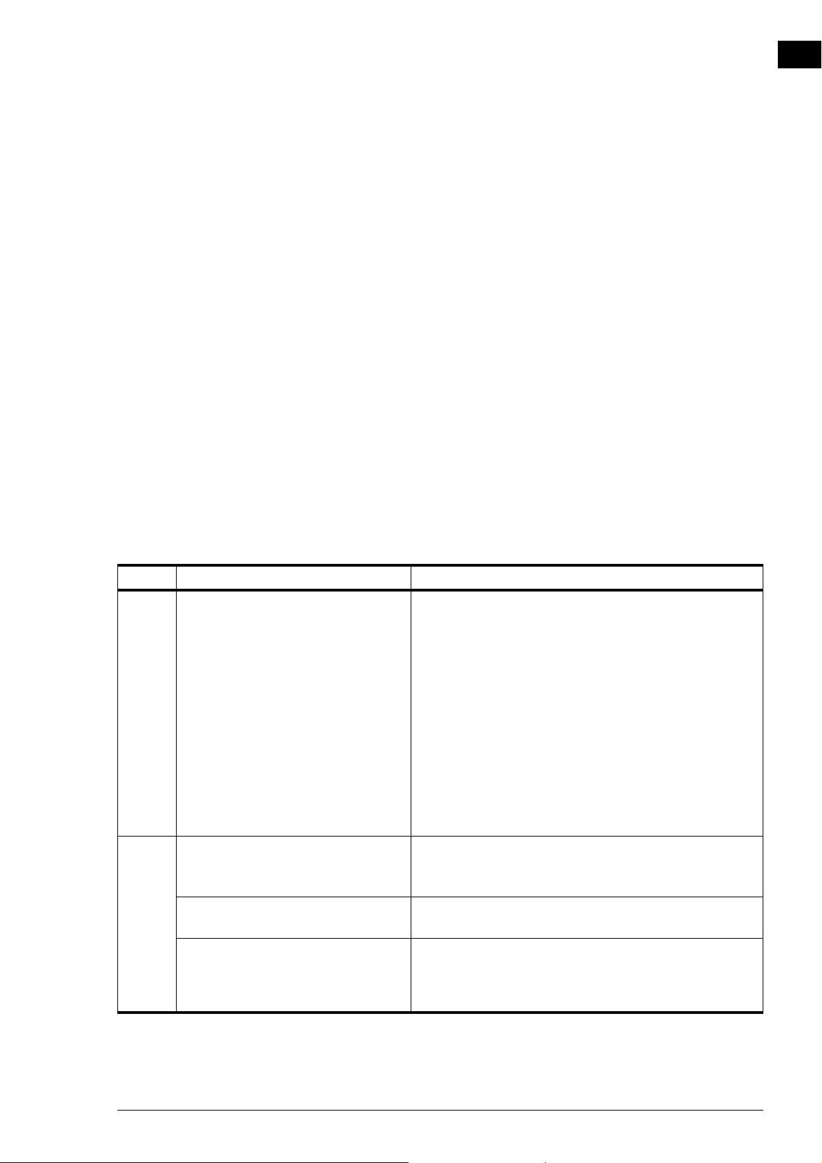
NOZ2 MANUAL ERRORS
5.2.2 Deleting errors
Most error messages will disappear automatically when the
problem is resolved. Certain errors have to be remedied,
however, by deleting the error message via
menu > Maintenance > Current errors.
5.2.3 Reset system
Some errors can be remedied by resetting the control panel
via menu > Maintenance > Reset system: the panel will then
search for connected units again.
In this process, all settings are retained.
5.3 Remedying errors that are accompanied by an error message
en
For models with b-touch control panel: Try t o r em ed y e rr o rs
that are accompanied by an error message, making use of the error
codes table. Technical expertise is required for this.
ODE PROBABLE CAUSE WHAT TO DO
C
E1 The control panel does not communi-
cate with one or more connected
units.
This error may occur:
• when a connected unit is removed
or replaced,
• due to a brief error in the power
supply of a connected unit,
• due to incorrect cabling,
• due to a fault.
E2 There are units connected that have an
invalid or unknown unit code, or an
invalid combination of unit types.
The control panel software is outdated. Check the version number of the software via
The control panel does have power but
is not communicating with any unit.
1. Check whether all connected units are provided with
mains supply.
2. Check whether the dummy plug on terminal X535 of the
last connected unit is present.
3. Check the control cables:
• are they correctly connected and free of breaks?
• are they stretched out or rolled up in a bifilar coil?
• are they shielded from magnetic fields?
4. Check the fuses.
5. Check the wiring between the control panel and connections X530 and X535 and X60 in the unit.
6. Reset the system if the error message does not automatically disappear.
Check and compare the unit types on the type plate. The
units must have the same battery type and preferably the
same capacity.
menu > Maintenance > Status.
1. Check the control cables:
• are they properly connected and fully intact?
• are they stretched out or rolled up in a bifilar coil?
• are they shielded from magnetic fields?
Manual version 6.0 - North America (10-03-2017) en-67
Page 68
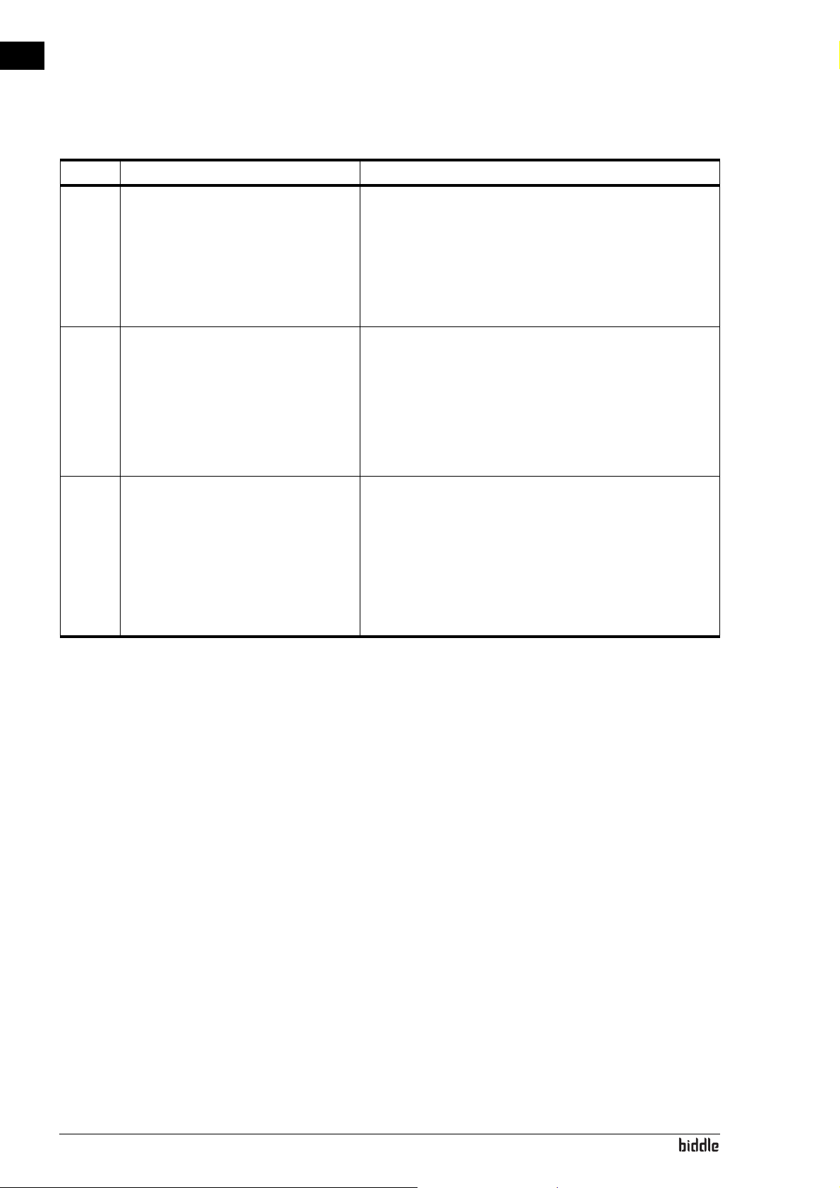
en
ERRORS AIR HEATER
C
ODE PROBABLE CAUSE WHAT TO DO
E6 For water-heated models:
Risk of freezing because discharge temperature is too low. Frost protection
has been activated.
Freezing may cause damage to
the heat exchanger.
E7 Fan error. 1. Clear the error message
F2 For water-heated models:
There is too much heating.
This error may occur if the control
valve does not work correctly.
1. Clear the error message.
2. Ensure that the temperature in the room rises above 8
ºC(47 ºF).
3. Follow the instructions for error code F3
You can prevent this error by setting the unit to switch on
the central heating system when there is a risk of freezing
(Function 61. Function of outputs on Heating on).
2. Check the fans. If one or more fans do not work, then
check:
• the fan wiring;
• the connections on the control circuit board (X344);
• the transformer fuse;
• the transformer itself.
If these are in order, then replace the fan.
1. Switch the unit OFF using the control panel, wait for one
minute, and switch it ON again.
2. Check that the connections of the supply and return
pipes have not been interchanged.
3. Check the wiring and connectors of the valve drive (X67/
X370) and the discharge temperature sensor (X350).
4. Remove the drive from the valve and check the interior
for mechanical operation and defects.
en-68
Page 69
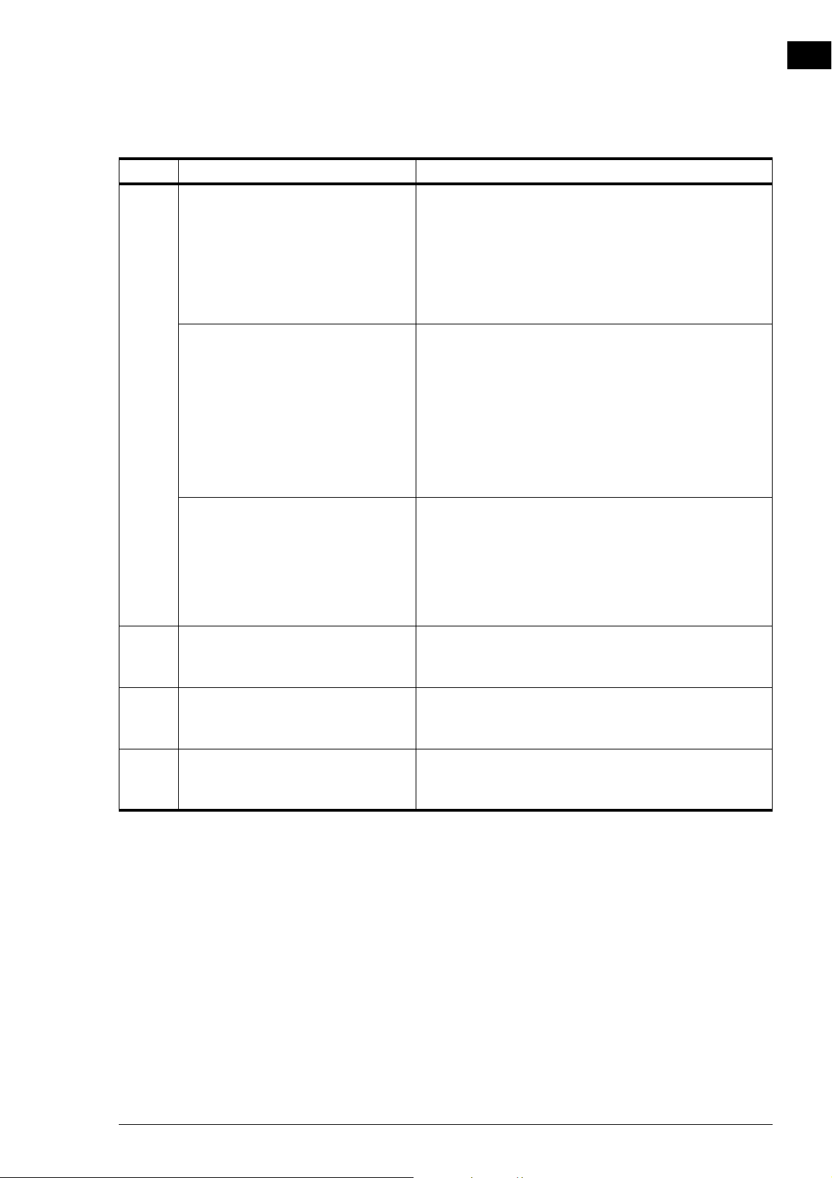
NOZ2 MANUAL ERRORS
C
ODE PROBABLE CAUSE WHAT TO DO
F3 For water-heated models:
The central heating system switches on
later than the unit.
Yo u c an :
• switch on the central heating system earlier;
• set the unit to turn on the central heating: Set
function 61. Function of outputs to Heating on and connect the relevant output to the central heating system.
• turn off this error message: Set function 21. User inter-
face options > Error display to Disable.
For water-heated models:
There is too little heating.
This error may occur:
• if not enough hot water is supplied;
• if the control valve does not work
correctly.
1. Check the central heating system:
•is it turned on?
• is it able to supply enough hot water?
2. Check whether the battery only becomes partially warm:
if so, it needs venting.
3. Check the wiring and connectors of the valve drive (X67/
X370) and the inlet temperature sensor (X360).
4. Remove the drive from the valve and check the interior
for mechanical operation and defects.
For all models:
If the fans do not rotate:
1. Check whether the fans are rotating. If one or more fans
do not work, check:
• the wiring of the fans;
• the connections on the printed circuit board (connectors X60);
• the transformer fuse;
• the transformer itself.
F5 The temperature sensor in the unit’s
discharge section does not work.
1. Check the sensor’s wiring and connection (connector
X350).
2. Replace the sensor.
F6 The temperature sensor in the unit’s
inlet section does not work.
1. Check the sensor’s wiring and connection (connector
X360).
2. Replace the sensor.
F13 On models with ventilation:
The temperature sensor in the ventilation air inlet does not work.
1. Check the wiring and connection of the sensor (connector X354).
2. Replace the sensor.
en
Manual version 6.0 - North America (10-03-2017) en-69
Page 70
en
ERRORS AIR HEATER
C
ODE PROBABLE CAUSE WHAT TO DO
F14 The room sensor does not work.
The indoor temperature is now based
on the temperature sensor in the inlet
section of the unit (corrected with an
estimated temperature difference
between the height of the room sensor
and the installation height of the unit)
F16 For models with Daikin direct expansion
system and electrical heating (type DKE):
Heating medium sensor does not
work.
The electrical heating is not switched
on in the defrost mode.
1. Check the sensor’s wiring and connection (connector
X540).
2. Replace the sensor.
1. Check the wiring and the connection of the medium sensor (connector X354)
2. Possibly, replace the sensor.
3. Possibly, activate the electrical heating via function >
Hybrid heating
5.4 Remedying errors that are not accompanied by an error mes-
sage
If you suspect an error but no error message is displayed:
1. Referring to the preceding sections, check whether you
can easily resolve the problem.
2. Try to resolve the problem using the table below. Technical expertise is required for this.
PROBLEM PROBABLE CAUSE WHAT TO DO
The control panel
works normally but
the unit does not
respond.
The display flickers The length of the control cable
The unit is being operated by a
signal from an external control.
The fans may be switched off if
there is only a small difference in
temperature between indoors
and outdoors.
between the control panel and
the first unit is too great
1. Check functions 60. Function of inputs and
Release delay input 1 in the menu Configuration.
This is not an error. If this is considered a problem,
the value of the function can become 42. Fan OFF
temperature.
Remove excessive length of cable
en-70
Page 71
NOZ2 MANUAL ERRORS
P
ROBLEM PROBABLE CAUSE WHAT TO DO
The unit is not functioning, the display is
black and does not
react to touch.
The unit is not receiving power. Check the mains supply:
• isolation switch,
• unit has power.
• connections and wiring of the power supply.
The connection between the
control panel and the control
circuit board is not good.
1. Check the control cable.
2. Check the wiring between the connector plate
and the control circuit board (connectors X530
and X60).
The control circuit board is not
working; the LEDs on the control circuit board are not lit.
1. Check fuse F141.
2. Check the mains power cable (connector X01).
3. Replace the control circuit board.
The control panel is faulty. Check the control panel by connecting it to another
unit with another cable. Replace the control panel if it
is not working.
One fan does not
work.
The fan is not receiving a power
supply or is faulty.
1. Check the wiring of the fan.
2. Check the transformer fuse.
3. Replace the fan.
The fans do not work
at a particular speed
The connection to the relevant
branch is not good.
1. Check the transformer connections.
2. Check connector X60.
level.
The earth leakage circuit breaker switches
the unit off.
The earth leakage circuit
breaker present is not compliant.
Ensure that an earth leakage circuit breaker type B is
present, preferably 300 mA.
en
Manual version 6.0 - North America (10-03-2017) en-71
Page 72
en
Caution:
6. . Maintenance
6.1 Introduction
6.2 Safety instructions
This chapter comprises those maintenance activities that the
user himself can perform. Maintenance activities and repairs
that must be performed by an installer are described in chapter 7Service.
6.3 Cleaning the unit
Before opening the unit, follow the safety instructions in section 1.5.2 Safety issues relating to installation, maintenance and
servicing.
You can clean the exterior of the unit with a damp cloth and a
domestic cleaning agent. Do not use any solvents.
c Make sure that no water runs into the unit.
en-72
Page 73

NOZ2 MANUAL MAINTENANCE
Caution:
6.4 Replacing or cleaning the filter
A filter module is available as an accessory. This is mounted on
top of the unit.
This module contains a tray, inside which is the filter material.
By default, the filter tray contains a class G2 filter material. You
can clean the filter material with a vacuum cleaner, for
instance. After several cleanings, however, you must replace it.
New filters are available from Biddle.
1. Undo screws 1 and 2 (2 is not visible in the drawing,
but, just like 1, is located half-way along the side).
2. Remove tray 3 from the unit.
3. Clean or replace the filter material.
en
c When replacing the filter material, you must ensure
that you place the material with the correct side
facing upwards.
4. Place the tray back into the unit.
5. Fasten the screws again.
Manual version 6.0 - North America (10-03-2017) en-73
Page 74
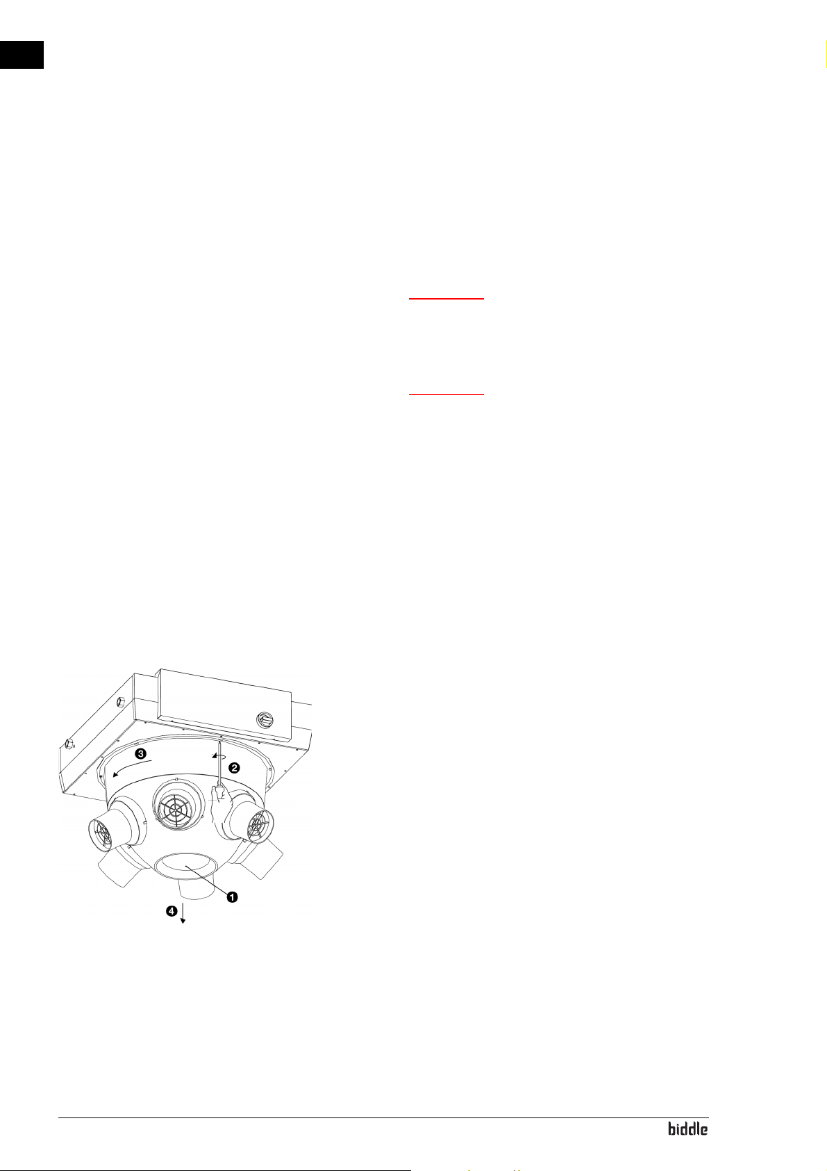
en
Warning:
Warning:
7. . Service
w Servicing activities may only be carried out by
personnel who are technically qualified to do
so.
w Before you begin: read the safety instructions.
See also:
1.5.2 "Safety issues relating to installation, maintenance and servicing" on page 12
7.1 Replacing the fan
1. Switch the unit off using the control unit.
2. Set the isolation switch to 0.
3. Detach the fan's mains power cable from the isolation
switch.
4. Undo the screw 1 in the base of the cone and remove the
screw.
5. Loosen the six screws of the cone somewhat 2, turn the
cone so that the screws fall through the wide part of the
keyhole 3 and remove the cone 4.
en-74
Page 75
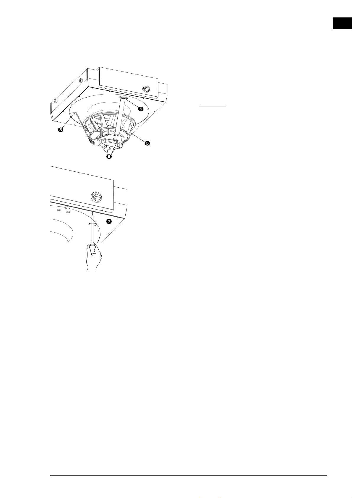
NOZ2 MANUAL SERVICE
Caution:
6. The fan is attached to the cabinet via a frame (three brack-
ets and a ‘fan seat’). Loosen the three bolts 5 which attach
this frame to the cabinet.
c The fan is heavy, and will fall if you unfasten these
bolts. Take firm hold of the fan.
7. The fan is attached to the frame with four bolts 6. Loosen
the bolts.
en
7.2 Electronics module
8. The base plate is attached to the cabinet with 16 (NOZ
25) or 20 (NOZ
remove the base plate.
9. Mount the whole thing in reverse order to the dismantling. If necessary, extend the mains power cable.
See also:
1 "Replacing the isolation switch" on page 1
Only for units which have automatic CHIPS control
The unit contains one electronics module. Depending on the
version, one can find on this such things as:
•the transformers;
50) screws. Loosen these screws 7 and
2
2
• the control circuit board;
• the connector plate;
• the fuses.
•the filters
•the reactor
Manual version 6.0 - North America (10-03-2017) en-75
Page 76
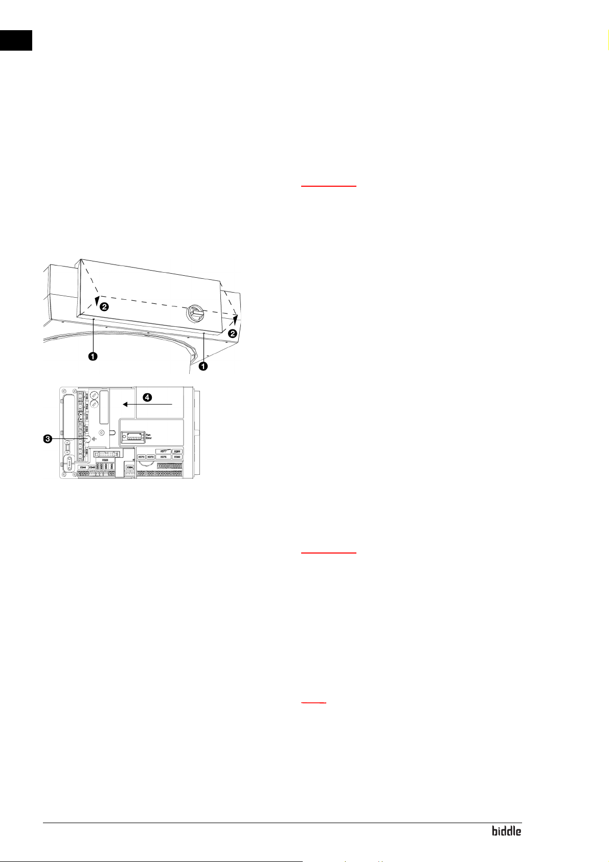
en
Warning:
Warning:
Note:
SERVICE AIR HEATER
7.3 Removing the control circuit board
1. Switch the unit off using the control panel.
w Shut off the mains supply.
The unit is fitted with 2 mains power cables.
Ensure that the power supply to the control
circuit board is also shut off.
2. Open the electronic housing: undo the screws 1 at the
bottom of the housing, tilt the cover 2 and lift the cover
off the unit.
3. Disconnect all connectors attached to the unit and earth
connections from the control circuit board.
4. Remove the screw 3.
5. Slide the control circuit board 4 loose and lift it out of the
unit.
7.4 Connecting the control circuit board
w Make sure that the mains supply is switched
off
1. Slide the control circuit board into its place and screw it in
firmly.
2. Connect all connectors and earth connections to the control circuit board again.
3. Switch the unit on and check the operation.
en-76
n With a new control circuit board, an E1 error may
occur because the old control circuit board can no
longer be found. Resolve this by reconfiguring the
system via menu > Maintenance > Reset system
Page 77
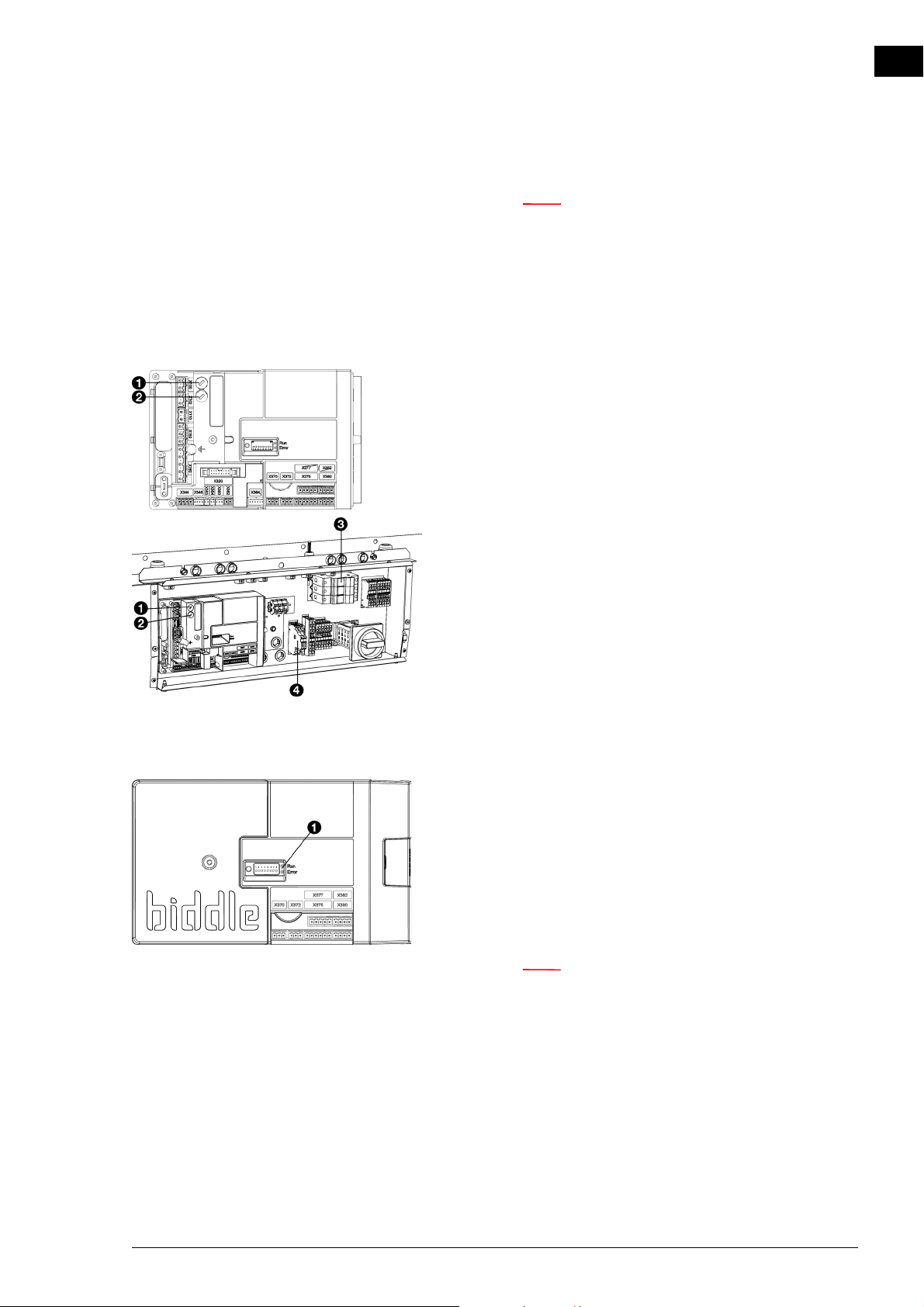
NOZ2 MANUAL SERVICE
Note:
Note:
n If you are asked to designate a new master unit, then
preferably select a unit whose control circuit board
has not been replaced. In that event, the settings will
be preserved.
7.5 Fuses
The control circuit board of the unit is fitted with the following fuses:
• fuse F140 1 of the transformer.
• fuse F141 2 of the control circuit board.
• fuses for the fans 3.
en
7.6 LEDs
-for the NOZ
-for the NOZ
-for the IndAC
-for the IndAC
The values are indicated on the fuses.
The LED lights 1 on the control circuit board indicate the following:
• continuous green: The control circuit board is receiving a
power supply.
• flashing green: The unit code can be entered.
• continuous red: There is a local error.
25, there are 2 fuses.
2
50, there are 3 fuses.
2
ST, there are 2 fuses.
2
MX, there are 3 fuses.
2
n This does not necessarily always result in an error
message on the control panel.
Manual version 6.0 - North America (10-03-2017) en-77
Page 78
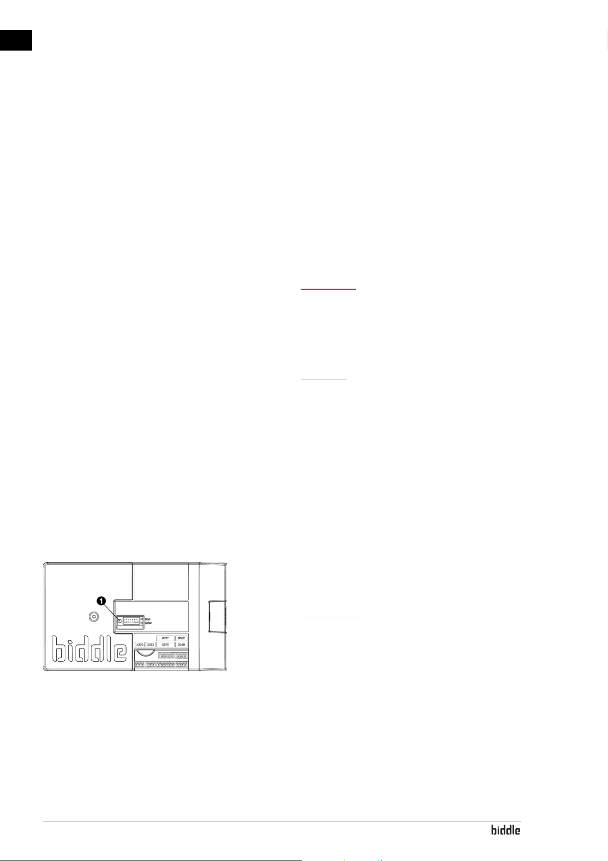
en
Warning:
Caution:
Warning:
SERVICE AIR HEATER
7.7 Setting the unit code
The unit code must be set after replacement of the control circuit
board in the unit. The unit code depends on the unit type and is
indicated on the type plate.
To set the unit code, there are two methods:
• directly via the control panel if a single unit is connected;
• via the control circuit board and the control panel if more
than one unit is connected.
w Entering an incorrect code will result in poor
performance of the unit.
7.7.1 Setting the unit code via the control panel
c Setting the unit code using this method will only
work if just a single unit is connected to the control
panel. If necessary, connect the control panel
separately to the unit in question.
1. Select menu > Maintenance > Unit code.
2. Enter the unit code via the control panel and press ok.
The control panel will now search for the unit again.
7.7.2 Setting the unit code via the control circuit
board and the control panel
1. Connect the mains supply (insert the plug into the socket
or move the isolation switch to ON).
w Do NOT touch any live parts.
en-78
2. Press down the microswitch 1 on the control circuit
board.
The LED next to the microswitch will start flashing.
The control panel displays eight numbers: these comprise
the unit code.
3. Enter the unit code via the control panel and press ok.
Page 79
NOZ2 MANUAL SERVICE
Note:
4. Press down microswitch.
The LED next to the microswitch will stop flashing.
The unit code is now set.
5. Reset the control panel.
7.8 Resetting the PIN code
The PIN code of the control panel can be reset using a USB
flash drive:
1. Connect a USB flash drive to the control panel.
The USB menu is activated
2. Press x for 10 seconds.
en
7.9 Copying the settings
The PIN code is reset and a new PIN code has to be
entered.
3. Exit the USB menu by removing the USB flash drive.
The settings of the unit can be copied to another unit.
7.9.1 What you need
Before copying the setting, check that you have the following:
• An empty USB flash drive. The USB flash drive must be formatted for FAT or DOS. Do not use a USB hard disk for
the software update.
7.9.2 Step 1: Copying the settings of the correctly-set
unit
1. Check whether the settings to be copied on the original btouch control panel are all correctly set.
2. Connect the USB flash drive to the USB port of the btouch control panel.
n If the USB flash drive is not detected, disconnect it
and then connect it again.
The control panel detects the USB flash drive and displays
the USB menu
Manual version 6.0 - North America (10-03-2017) en-79
Page 80
en
Note:
SERVICE AIR HEATER
3. Select Export Settings
The progress percentage is displayed.
4. When this has been completed, disconnect the USB flash
drive from the control panel.
7.9.3 Step 2: Copying the settings to another unit
1. Connect the USB flash drive (with the settings that are to
be copied) to the USB port on the other control panel.
2. Keep the function Import settings pressed down until the
progress of the process is displayed.
The settings are now being imported.
7.10 Updating the software
n Below the progress percentage, the name of the file
to be imported is visible:‘settings_export.txt’
3. When this has been completed, disconnect the USB flash
drive from the control panel.
4. Repeat steps 1 to 3 for each control panel to which you
wish to apply the same settings.
Biddle is working continuously on improving its products and
recommends that you update the software of the control
panel and of the control circuit board when updates become
available. Consult Biddle’s website for availability.
7.10.1 What you need.
Before updating the software of the control panel, check that
you have the following:
• An empty USB flash drive. The USB flash drive must be formatted for FAT or DOS. Do not use a USB hard disk for
the software update.
• A PC with Internet access.
en-80
Page 81
NOZ2 MANUAL SERVICE
Warning:
7.10.2 Step 1: Check the current software version
Before you update the software of the control panel or of the
control circuit board, you must check the existing software
version. If the software version is the same as that of the most
recent update file on Biddle’s website, you do not need to
update the software.
1. Press menu in the Home screen.
2. Select Maintenance. The version of the current software is
displayed in the status overview.
7.10.3 Step 2: Download the most recent software
1. Connect the USB flash drive to a USB port on your PC.
2. On your PC, go to Biddle’s website and look under Downloads.
en
3. Look for your product and the available software for your
unit.
4. If the software version is more recent than the version on
your control panel, click on the software update.
5. Accept the licence agreement and save the file to the main
directory of the USB flash drive.
6. Disconnect the USB flash drive from the PC.
7.10.4 Step 3: Updating the software
w Do not switch off the unit or disconnect the
USB flash drive during the software update.
Do not disconnect the USB flash drive from
the control panel even if there is a power
failure during the update. The update will
resume as soon as the power returns. If an
error occurs during the update, start the
procedure again. If the error continues to
occur, contact Biddle.
Manual version 6.0 - North America (10-03-2017) en-81
Page 82
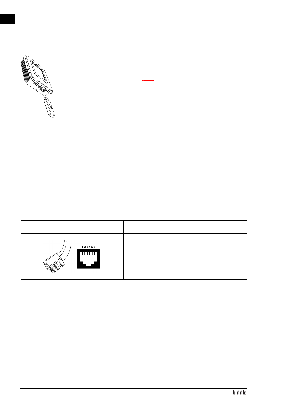
en
Note:
SERVICE AIR HEATER
1. Connect the USB flash drive (with the software update) to
the USB port on the control panel.
n If the USB flash drive is not detected, disconnect it
and then connect it again.
The control panel detects the USB flash drive and displays
the USB menu
2. Select Software update to update the software.
3. When this has been completed, disconnect the USB flash
drive from the control panel.
7.11 Composition of the Biddle control cable
The control cable for the control system is constructed as follows:
• The plugs are modular connectors of the type 6P4C.
• Connectors are untwisted, i.e. at both ends of the cable,
cores are connected to the same electrode.
Colour coding of Biddle cables
ELEC-
TRODE
1 (not used)
2black
3red
4 green
5yellow
6 (not used)
COLOUR
en-82
Page 83
8. . Dismantling
The dismantling of the installation and the handling of the
coolant, oil and other components must be carried out by a
qualified fitter in accordance with the relevant local and
national legislation and regulations.
By ensuring that this product is disposed of in the correct
manner, you are helping to prevent potential negative consequences for the environment and public health. For more
information about this, please contact your supplier or the relevant government authority.
en
Manual version 6.0 - North America (10-03-2017) en-83
Page 84
en
DISMANTLING AIR HEATER
en-84
Page 85
9. . Addresses
If you have any comments or queries relating to this product,
please do not hesitate to contact your Biddle branch.
en
Biddle bv
P. O. B ox 15
9288 ZG Kootstertille
The Netherlands
Manual version 6.0 - North America (10-03-2017) en-85
Biddle Air Systems Ltd.
11 King St. Unit #3
Barrie, ON L4N 6B5
Canada
Page 86

en
AIR HEATER
. . . Keywords
A
accessories . . . . . . . . . . . . . . . . . . . . . . . . 11
addresses . . . . . . . . . . . . . . . . . . . . . . . . . 85
adjusting the nozzle angle . . . . . . . . . . . . 21
alarm signal . . . . . . . . . . . . . . . . . . . . . . . 38
application limits . . . . . . . . . . . . . . . . . . . . 8
B
BACnet . . . . . . . . . . . . . . . . . . . . . . . . . . 40
battery type . . . . . . . . . . . . . . . . . . . . . . . . 7
baud rate . . . . . . . . . . . . . . . . . . . . . . . . . 40
C
capacity . . . . . . . . . . . . . . . . . . . . . . . . . . . 7
central heating system . . . . . . . . . . . . . . . 23
CHIPS control . . . . . . . . . . . . . . . . . . . . . . 6
cleaning . . . . . . . . . . . . . . . . . . . . . . . . . . 72
communication parameters. . . . . . . . . . . 40
connecting power supply. . . . . . . . . . . . . 28
connecting the piping. . . . . . . . . . . . . . . . 23
control . . . . . . . . . . . . . . . . . . . . . . . . . . . . 7
control cable . . . . . . . . . . . . . . . . . . . . . . 82
control valve . . . . . . . . . . . . . . . . . . . . . . 24
D
delivery inspection . . . . . . . . . . . . . . . . . . 14
designations . . . . . . . . . . . . . . . . . . . . . . . . 4
detaching the inlet grille . . . . . . . . . . . . . 18
determine location . . . . . . . . . . . . . . . . . 16
disable . . . . . . . . . . . . . . . . . . . . . . . . . . . 46
discharge temperature, maximum. . . . . . . 8
dismantling . . . . . . . . . . . . . . . . . . . . . . . . 83
E
electronics module . . . . . . . . . . . . . . . . . 75
errors. . . . . . . . . . . . . . . . . . . . . . . . . 51, 64
delete . . . . . . . . . . . . . . . . . . . . . . . . 67
reading out. . . . . . . . . . . . . . . . . . . . 66
F
filter
cleaning . . . . . . . . . . . . . . . . . . . . . . 73
replacing . . . . . . . . . . . . . . . . . . . . . 73
finishing . . . . . . . . . . . . . . . . . . . . . . . . . . 42
frost protection. . . . . . . . . . . . . . . . . . . . 27
fuses. . . . . . . . . . . . . . . . . . . . . . . . . . . . . 77
I
installation . . . . . . . . . . . . . . . . . . . . . . . . 14
b-control . . . . . . . . . . . . . . . . . . . . . 31
b-touch . . . . . . . . . . . . . . . . . . . . . . 34
damper module . . . . . . . . . . . . . . . . 20
external controls. . . . . . . . . . . . . . . 37
filter module . . . . . . . . . . . . . . . . . . 19
roof cowl . . . . . . . . . . . . . . . . . . . . . 17
ventilation duct . . . . . . . . . . . . . . . . 20
installing control unit
b-control . . . . . . . . . . . . . . . . . . . . . 31
b-touch . . . . . . . . . . . . . . . . . . . . . . 34
installing ventilation duct. . . . . . . . . . . . . 20
M
mains supply . . . . . . . . . . . . . . . . . . . . 7, 28
maintenance. . . . . . . . . . . . . . . . . . . . . . . 72
Modbus . . . . . . . . . . . . . . . . . . . . . . . . . . 40
modifications . . . . . . . . . . . . . . . . . . . . . . 10
mounting filter module . . . . . . . . . . . . . . 19
mounting the damper module . . . . . . . . 20
O
operating package . . . . . . . . . . . . . . . . . . 11
operating pressure, maximum . . . . . . . . . 8
operation
b-control . . . . . . . . . . . . . . . . . . . . . 46
b-touch . . . . . . . . . . . . . . . . . . . . . . 47
en-86 B
Page 87
NOZ2 MANUAL
en
P
parity. . . . . . . . . . . . . . . . . . . . . . . . . . . . . 40
PIN code . . . . . . . . . . . . . . . . . . . . . . . . . . 79
power . . . . . . . . . . . . . . . . . . . . . . . . . . . . . 8
power supply voltage . . . . . . . . . . . . . . . . . 8
problems. . . . . . . . . . . . . . . . . . . . . . . . . . 64
product series. . . . . . . . . . . . . . . . . . . . . . . 7
R
regulating the discharge direction . . . . . . 21
replacing fan . . . . . . . . . . . . . . . . . . . . . . . 74
roof cowl
mounting . . . . . . . . . . . . . . . . . . . . . . 17
mounting to unit . . . . . . . . . . . . . . . . 21
room sensor . . . . . . . . . . . . . . . . . . . . . . . 38
S
safety instructions
installation. . . . . . . . . . . . . . . . . . 12, 14
maintenance . . . . . . . . . . . . . 12, 64, 72
service. . . . . . . . . . . . . . . . . . . . . 12, 74
usage . . . . . . . . . . . . . . . . . . . . . . . . . 12
service. . . . . . . . . . . . . . . . . . . . . . . . . . . . 74
servomotor. . . . . . . . . . . . . . . . . . . . . . . . 31
stop bits . . . . . . . . . . . . . . . . . . . . . . . . . . 40
strength. . . . . . . . . . . . . . . . . . . . . . . . 46, 50
suspension. . . . . . . . . . . . . . . . . . . . . . . . . 18
switching ON . . . . . . . . . . . . . . . . . . . 42, 46
symbols . . . . . . . . . . . . . . . . . . . . . . . . . . 4, 5
U
unit code. . . . . . . . . . . . . . . . . . . . . . . . . . 78
updating software. . . . . . . . . . . . . . . . . . . 80
USB. . . . . . . . . . . . . . . . . . . . . . . . . . . . . . 61
V
ventilator . . . . . . . . . . . . . . . . . . . . . . . . . 74
W
water flow-path, maximum . . . . . . . . . . . . 9
water-side control . . . . . . . . . . . . . . . . . . 24
wiring . . . . . . . . . . . . . . . . . . . . . . . . . . . . 40
wiring diagram . . . . . . . . . . . . . . . . . . . . . . 5
working method. . . . . . . . . . . . . . . . . . . . 14
T
type code . . . . . . . . . . . . . . . . . . . . . . . . . . 7
type designation . . . . . . . . . . . . . . . . . . . . . 7
type plate . . . . . . . . . . . . . . . . . . . . . . . . . . 8
Typeaanduiding . . . . . . . . . . . . . . . . . . . . . . 7
Manual version 6.0 - North America (10-03-2017) en-87
Page 88
en
Copyright and Trademarks
All information and drawings contained in this manual are the property of Biddle and may not be used (other than
for the purpose of unit operation), photocopied, reproduced, translated and/or communicated to third parties
without prior written permission from Biddle.
The name Biddle is a registered trademark of Biddle bv.
Warranty and liability
For the warranty and liability provisions and terms, please refer to the terms & conditions of sale and supply.
At all times, Biddle shall not be held liable for consequential damages.
Liability as regards the manual
Although great care has been taken to ensure the correct and, where necessary, complete description of the
relevant components, Biddle shall not be held liable for damages as a consequence of errors and/or imperfections
in this manual.
Biddle reserves the right to alter the specifications as mentioned in this manual.
Should you nevertheless discover any errors or ambiguities in the manual, we shall be glad to learn that from you.
It helps us to improve the documentation still further.
For more information
If you have any comments or queries relating to this product, please do not hesitate to contact Biddle. You will find
the contact information for your Biddle branch in chapter 9 Addresses.
Biddle bv
P.O. Box 15
9288 ZG Kootstertille
The Netherlands
Name and telephone number of installer:
 Loading...