

Page 1
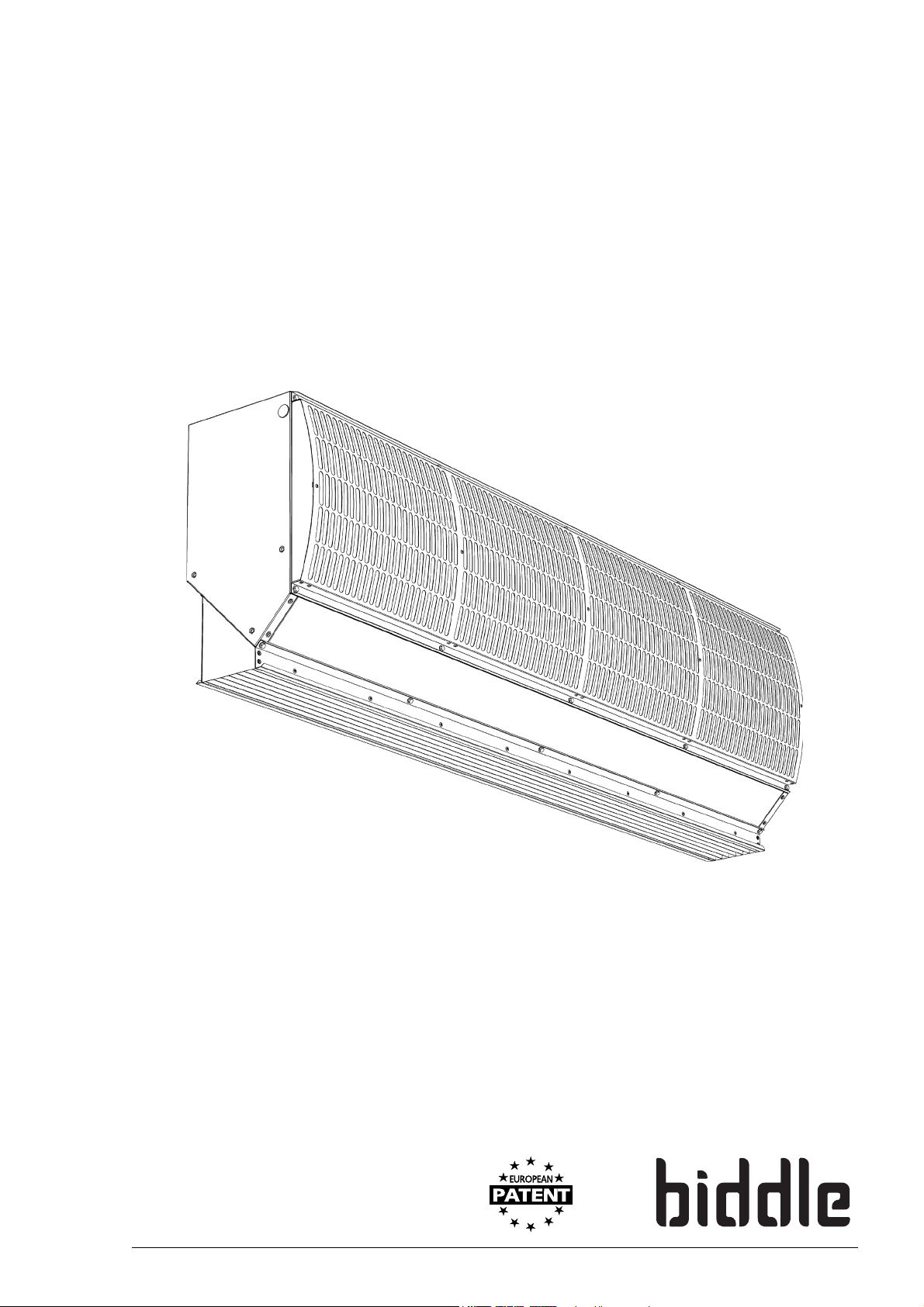
Manual
Cold room air curtain
Model IsolAir
Version 1.1
Original Manual
a
English
Page 2

en
COLD ROOM AIR CURTAIN
. . . Contents
1 Introduction 3
1.1 About this manual 3
1.2 How to read this manual 3
1.3 About the unit 4
1.4 Components and accessories 7
1.5 Safety instructions 8
2 Installation 9
2.1 Safety instructions 9
2.2 Inspection on delivery 9
2.3 General working methlod 10
2.4 Hanging the unit up 11
2.5 Installing the control box 15
2.6 Installing external controls 18
2.7 Connecting the mains supply 20
2.8 Finishing the unit 22
2.9 Switching on and checking operation 22
3Operation 23
3.1 General 23
4Errors 24
4.1 Resolving simple problems 24
5 Maintenance 25
5.1 Cleaning the unit 25
5.2 Scheduled maintenance 25
6Service 26
6.1 Safety instructions 26
6.2 Replacing a fan box 26
6.3 Fuses 28
6.4 Adjusting modes 28
7Dismantling 31
8Addresses 33
Keywords 35
en-2 B
Page 3
1. . Introduction
Note:
Caution:
Warning:
1.1 About this manual
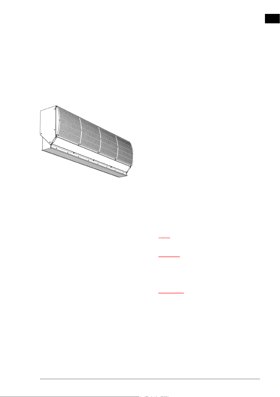
This manual describes the installation, operation and maintenance of the the cold storage unit air curtain model IsolAir.
The manual also provides instructions and information for servicing activities.
en
1.2 How to read this manual
1.2.1 Designations used in the manual
The following symbols are used in the manual:
n Refers to an important section in the text.
c If you do not carry out the procedure or action
correctly, you may cause damage to the unit.
Follow the instructions precisely.
w If you do not carry out the procedure or
action correctly, you may cause physical injury
and/or damage.
Follow the instructions precisely.
Manual version 1.1 (07-04-2016) en-3
Page 4
en
Danger:
INTRODUCTION COLD ROOM AIR CURTAIN
d Is used to designate actions that are not
permitted.
Ignoring this prohibition may lead to serious
damage or to accidents resulting in physical
injury.
1.2.2 Symbols used on the unit and in the manual
The following symbols indicate possible risks or hazards. The
same symbols will also be found on the unit.
S
YMBOL DESCRIPTION
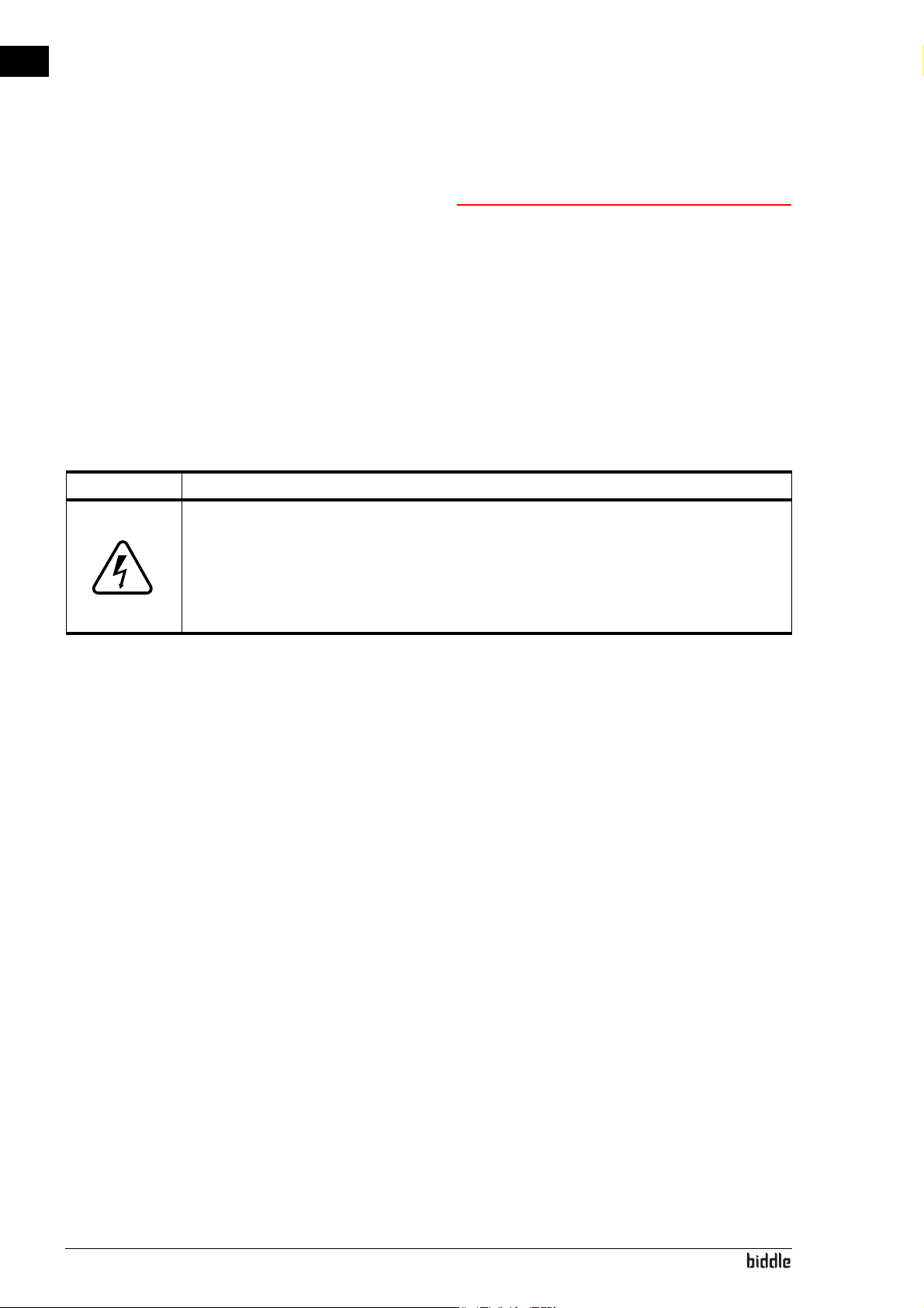
w You have accessed a section of the unit with components carrying a volt-
age.
Access restricted to qualified maintenance staff only.
Caution is required.
1.3 About the unit
1.2.3 Related documentation
In addition to this manual, the following documentation is also
supplied with the unit:
• wiring diagram for installation and servicing.
1.3.1 Applications
The air curtain model IsolAir is intended for the separation of
climates between two rooms. The unit is installed above the
doorway, across its full width. The model is primarily suitable
for applications in cold-storage and deep-freeze units.
en-4
Other versions and intended use.
Upon request, we can supply versions for non-standard applications.
Page 5
ISOLAIR MANUAL INTRODUCTION
Warning:
w Applications other than those described
above are deemed to be ‘usage other than for
the intended purpose’. Biddle is not liable for
damage or loss resulting from usage other
than for the intended purpose. Usage for the
intended purpose also entails observance of
the instructions in this manual.
1.3.2 Operation
The air curtain blows out a stream of air straight downwards
and thereby achieves the following:
• The exchange of air between two rooms due to a temperature difference (convection) is stopped.
en
Depending on the setting of the air curtain, the unit can also
blow out unheated air.
1.3.3 Type designation
The table below provides an overview of the available models
of the cold room air curtain and the corresponding type designations. In combination, the type designations constitute the
type code, for instance: IsolAir150.
If some part of the manual applies to certain models only,
these will be indicated with the corresponding type designation, for example:
• 150: models with discharge width 150
Explanation of the type code
T
YPE CODE ELEMENT DESIGNATION MEANING
product series IsolAir general designation for the IsolAir series
length 150, 200 or 250 discharge length in cm
Manual version 1.1 (07-04-2016) en-5
Page 6
en
Warning:
INTRODUCTION COLD ROOM AIR CURTAIN
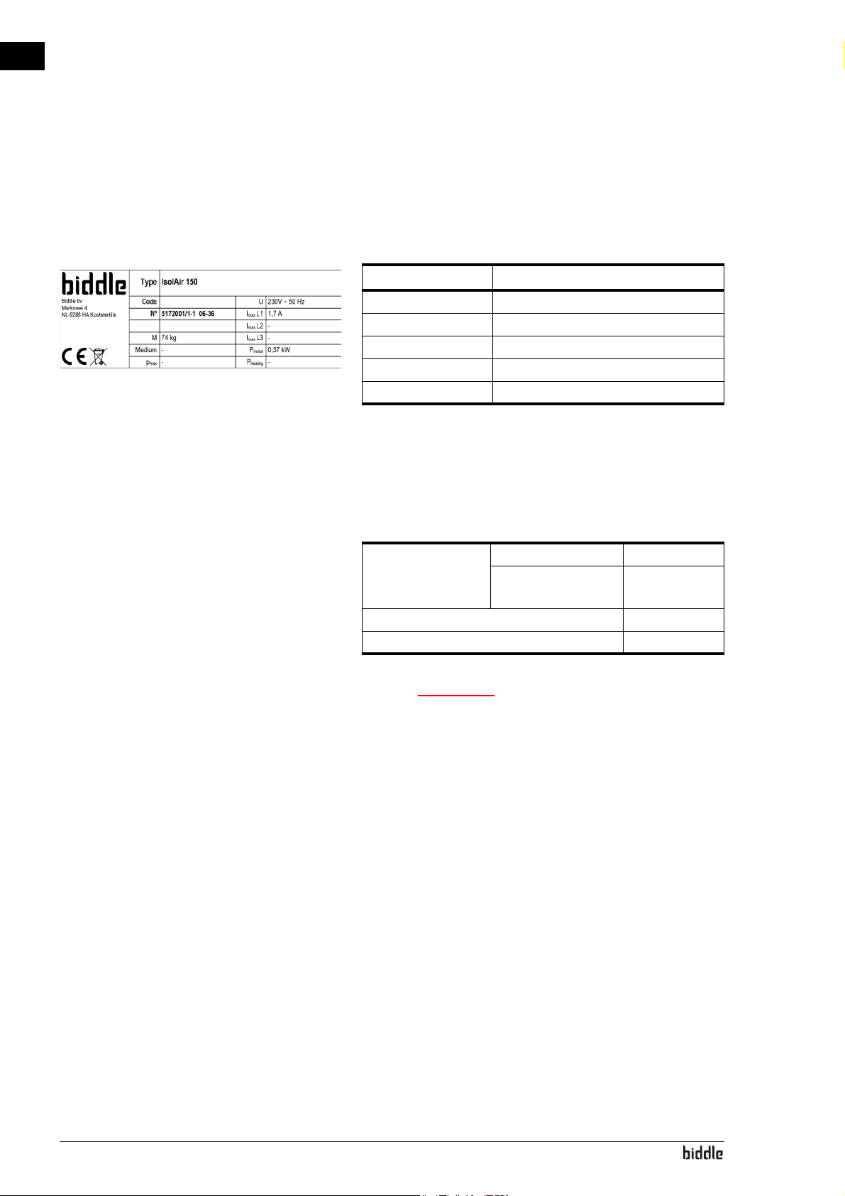
1.3.4 Type plate
The type plate is located on the top of the unit.
Example of a type plate Designations on the type plate
DESIGNATION MEANING
Type complete type code of the unit
Mweight of unit
U power supply voltage
I
max
P
motor
1.3.5 Field of application
max. current
max. power consumption by fans
Observe the following limits for the unit:
Operating limits for all models
Ambient conditions Temperature 5 °C to 40°C
Relative air humidity 20% - 95%, not
condensing
Power supply voltage see type plate
Power see type plate
w The air curtain may not be used in potentially
explosive environments.
Biddle shall not be held liable for damage caused by
use under these conditions.
1.3.6 CE declaration
The unit is compliant with the applicable CE standards. The
complete CE Declaration of Conformity can be found at:
www.biddle.info
en-6
1.3.7 Modifications and changes
Without the approval of Biddle, no changes or modifications
may be made to the unit that could adversely affect safety. The
CE declaration is no longer valid if the unit has been modified
or changed in any way.
Page 7
ISOLAIR MANUAL INTRODUCTION
Note:
1.4 Components and accessories
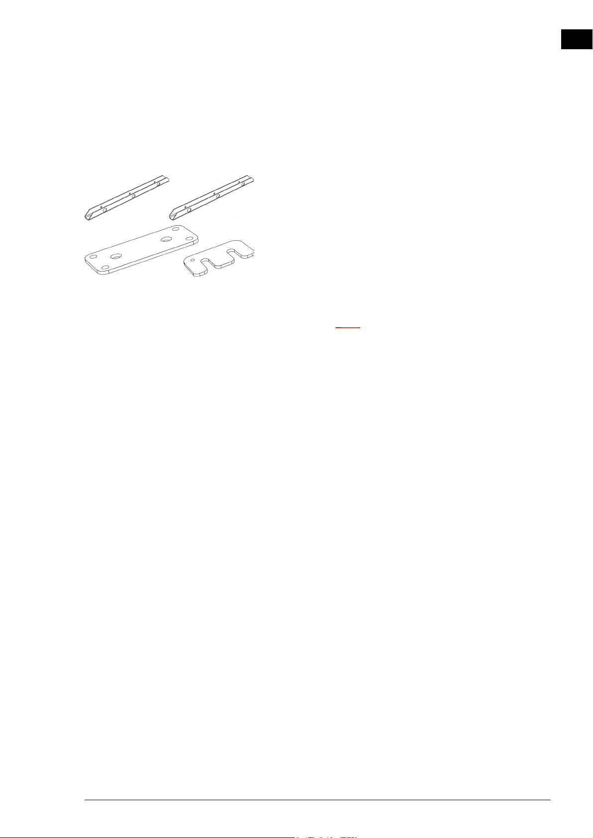
1.4.1 Components supplied
• suspension rails (2 per unit), also used for fixing the unit to
the pallet
• coupling plate and bracket for coupling the units:
• operating package:
-control box
- door contact switch
- room thermostat (optional)
en
n For delivery purposes, some components may be
packed within the unit (behind the inspection panel).
1.4.2 Accessories
• plastic side shields;
1.4.3 Components not supplied
The following components required for installation must be
obtained from third parties:
• threaded rods (M8)
• other cabling
•isolation switch
Manual version 1.1 (07-04-2016) en-7
Page 8
en
Warning:
Warning:
Danger:
Warning:
Danger:
INTRODUCTION COLD ROOM AIR CURTAIN
1.5 Safety instructions
1.5.1 Safety in use
w Do not put any objects into the inlets and
outlets.
w Do not obstruct the unit’s inlets or outlets.
1.5.2 Safety issues relating to installation, maintenance and servicing
d The unit may only be opened by qualified
technical staff.
w Perform the following actions before opening
the unit:
1. Switch the unit off using the control panel.
2. Wait until the fans have stopped.
d The fans may continue rotating for a while.
3. Disconnect the mains supply ( set the isolation switch to
OFF).
en-8
Page 9

2. . Installation
Warning:
Warning:
2.1 Safety instructions
w Installation activities may only be performed
en
by technical staff qualified for this purpose.
2.2 Inspection on delivery
w Before starting installation: read the safety
instructions.
See also:
1.5 "Safety instructions" on page 8
• Check the unit and the packaging to ensure they have been
delivered in good order. Notify the driver and the supplier
immediately if any shipping damage is detected.
• Ensure that all components are present. Notify supplier of
any missing parts immediately.
See also:
1.4 "Components and accessories" on page 7
Manual version 1.1 (07-04-2016) en-9
Page 10

en
Caution:
Note:
Note:
INSTALLATION COLD ROOM AIR CURTAIN
2.3 General working methlod
2.3.1 Sequence of operations
Biddle recommends working as follows when installing the
unit:
1. Hang the unit up.
2. Install the control box.
3. Install any applicable external controls.
4. Connect the unit to the mains supply.
c Make sure that the unit’s power supply voltage
matches the local mains voltage.
The unit’s power supply voltage is displayed on the
type plate.
5. Complete the installation of the unit.
6. Switch the mains supply on and check that the unit is
working properly.
2.3.2 General instructions
Some parts of this section only apply to certain models.
Where this is the case, it will be indicated. If no specific model
is referred to, then the description applies to all models.
n Make sure that you perform all installation
operations that are applicable to your unit.
Check the type plate and consult the manual if in
doubt about the model or type of your unit.
en-10
n During the installation period, protect the unit
against damage and penetration of dust, cement, etc..
You can, for instance, use the packaging for
protection.
See also:
1.3.3 "Type designation" on page 5
1.3.4 "Type plate" on page 6
Page 11
ISOLAIR MANUAL INSTALLATION
Warning:
Note:
Warning:
2.4 Hanging the unit up
2.4.1 Suspension method
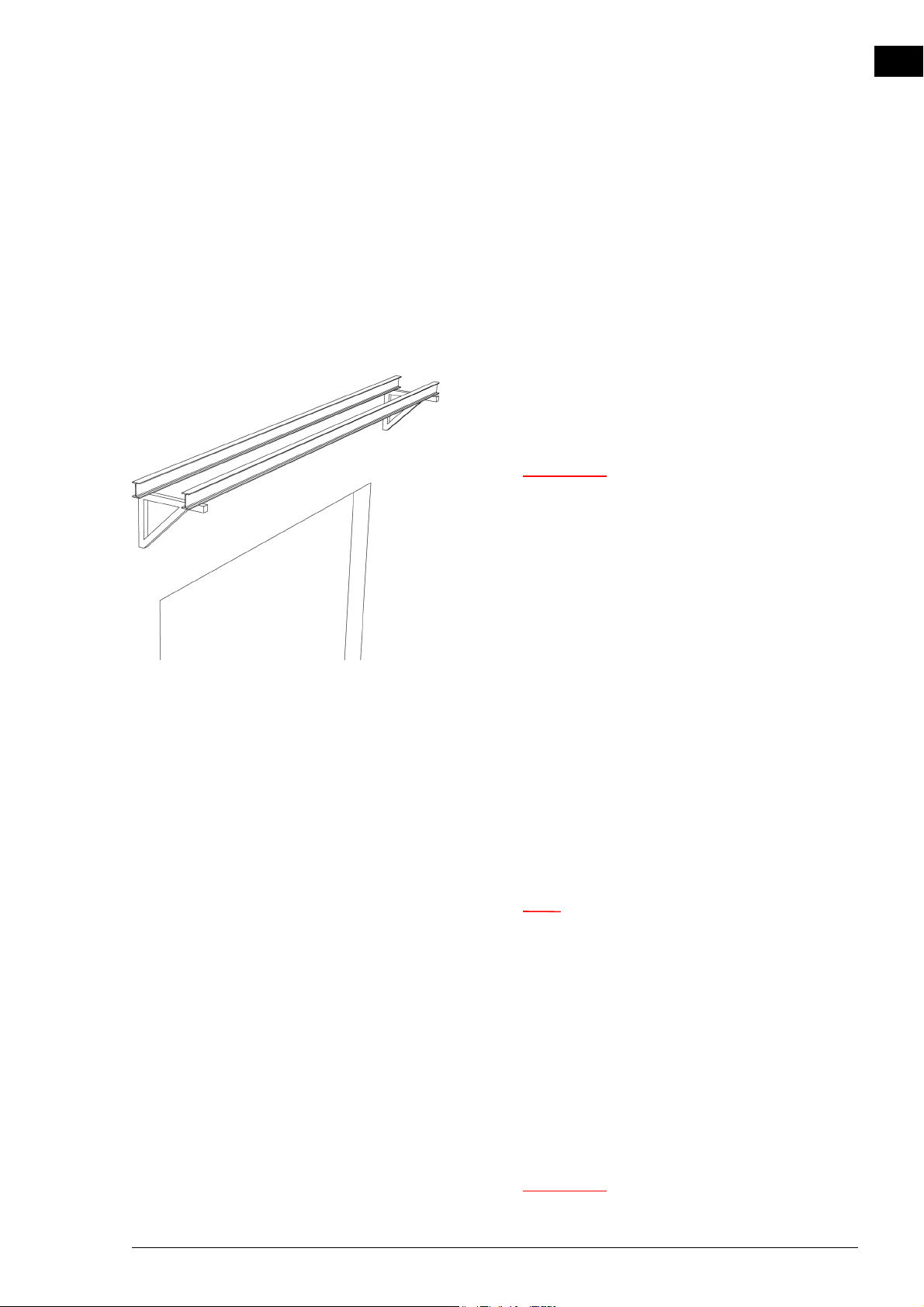
Example of an auxiliary structure This manual assumes suspension from an auxiliary structure,
consisting of two horizontal beams positioned above the door.
You may also fix the units directly to the ceiling, or to another
horizontal structure, using the screw holes in the upper side
of the unit.
w Make sure that the structure from which the
unit is about to be suspended can bear at
least 4 times the weight of the unit.
en
See also:
1.3.4 "Type plate" on page 6
2.4.2 Determine the location of the unit
• The unit should preferably be placed in the room where
the temperature is highest.
• Position the underside of the unit at the same height as the
top of the doorway.
• Position the discharge side of the unit as close to the doorway as possible, to ensure optimum operation.
n If the distance is greater than 5 cm., you are advised
to seal off the openings at the side. For this purpose,
you can order a side shield of plastic strips from
Biddle.
• Position the row of units centrally in relation to the doorway.
• Units of different widths can be positioned in random
order.
• Make sure that the inspection and intake sides of the units
remain accessible for maintenance.
w Make sure that all units can freely take in and
blow out air across their entire width.
Manual version 1.1 (07-04-2016) en-11
Page 12
en
Note:
INSTALLATION COLD ROOM AIR CURTAIN
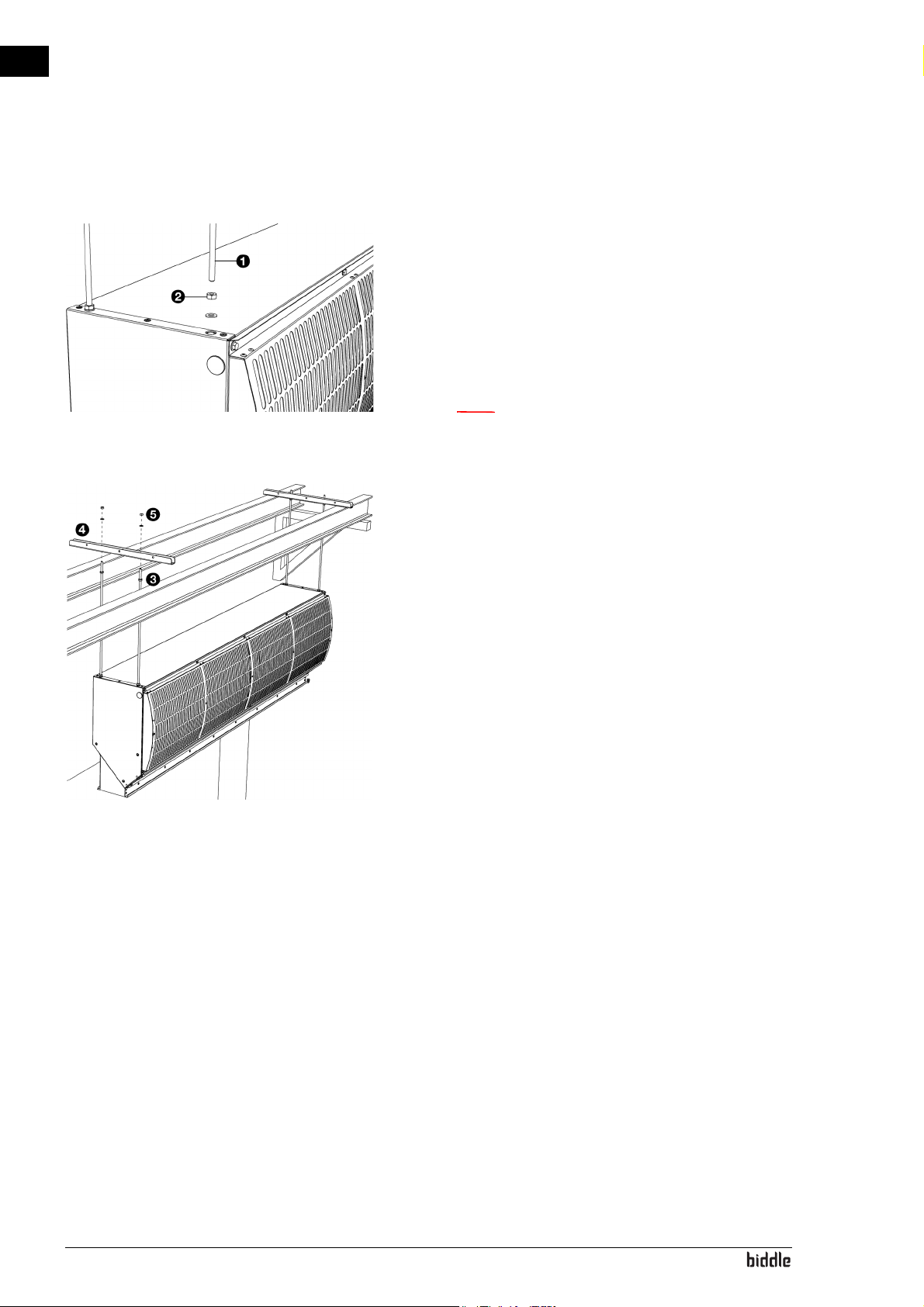
2.4.3 Hanging the unit up
Perform the following actions for each unit:
1. Lay the unit in a horizontal position.
2. Fit threaded rods 1 (M8) in all screw holes on the top of
the unit.
3. Provide all threaded rods with lock nuts 2, and tighten
them.
n The threaded rods must be secured, otherwise the
unit may fall down.
4. Provide all threaded rods with lock nuts 3.
5. Bring the unit into position using lifting equipment.
6. Put the suspension rails 4 on the auxiliary structure, and
fasten them with nuts 5 to the threaded rods of the unit.
7. Allow the unit to hang freely.
en-12
Page 13
ISOLAIR MANUAL INSTALLATION
Warning:
Caution:
Warning:
Caution:
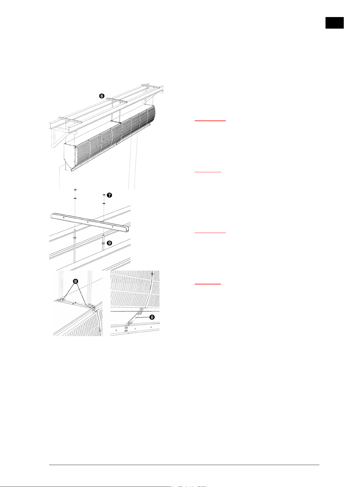
2.4.4 Adjusting and securing
1. Position the units against one another, in one line, by plac-
ing the suspension rails 6 against one another.
2. Attach the suspension rails to the auxiliary structure.
w Make sure that the suspension rails can never
come loose from the auxiliary structure.
3. Adjust the units to the same height, and level them by
tightening the nuts 7.
c Ensure that the units are hanging level and horizontal
in both directions. Otherwise the fans may run out
of true.
en
4. Secure the suspension to the threaded rods by tightening
the lock nuts 9.
w The threaded rods must be secured,
otherwise the unit may fall down.
5. You can possibly fasten the units to each other, using the
brackets and the coupling plate 8.
c First position the units independently of each other,
so that no force is exerted on the coupling elements.
Manual version 1.1 (07-04-2016) en-13
Page 14
en
INSTALLATION COLD ROOM AIR CURTAIN
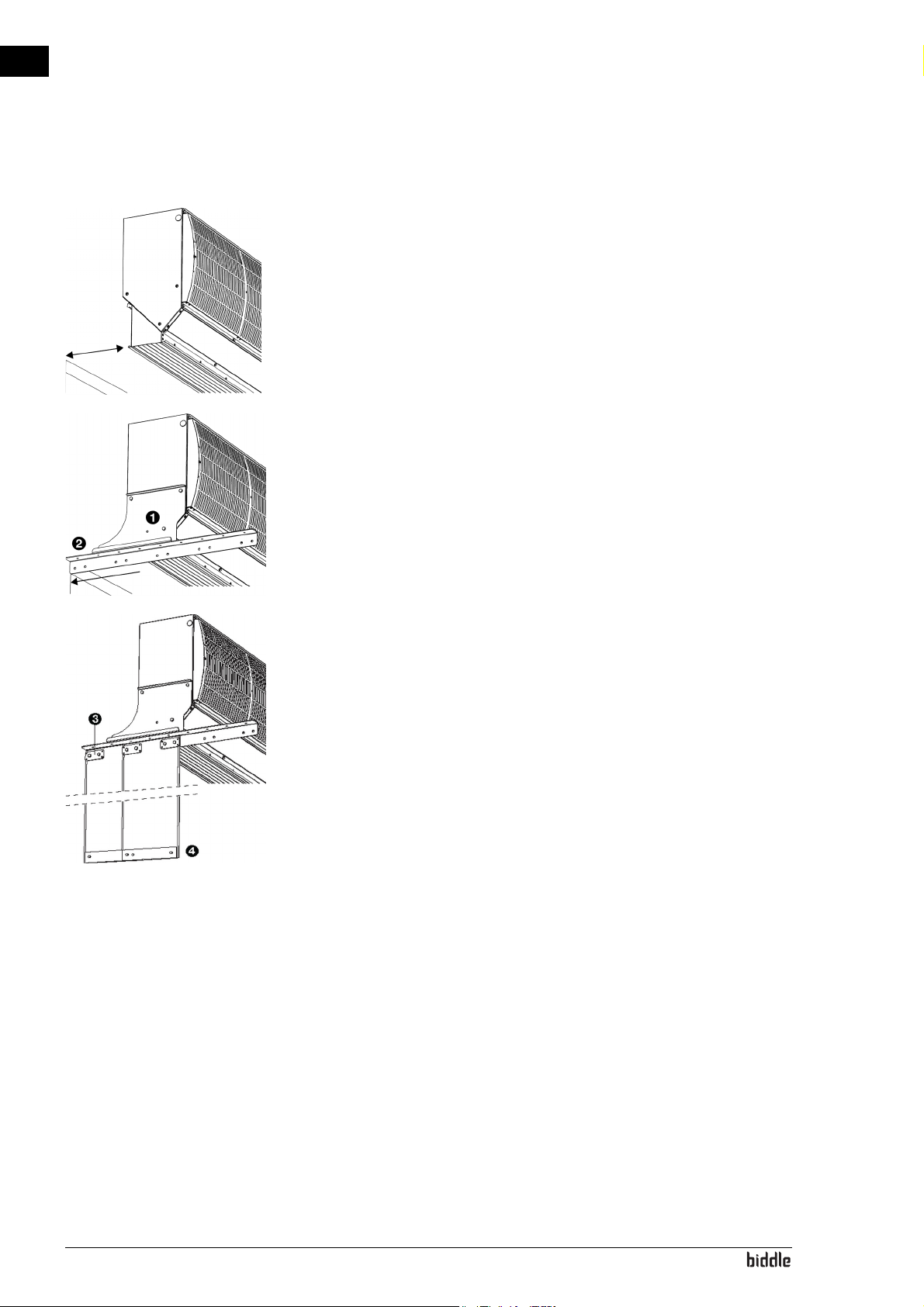
2.4.5 Installing side shield
For optimum operation, the unit’s discharge opening must be
placed as close as possible to the door opening. If the distance is greater than 5 cm., you are advised to seal off the
openings at the side.
For this purpose, you can order a side shield of plastic strips
from Biddle.
1. On both sides of the unit, mount a side plate 1.
2. To each side plate, fasten an angle profile, reaching to the
wall 2.
3. Cut the plastic strips to size.
4. Fasten the strips to the suspension system 3.
5. Fasten the steel plates at the bottom of the strips 4.
en-14
Page 15
ISOLAIR MANUAL INSTALLATION
Warning:
Warning:
Caution:
Warning:
Note:
2.5 Installing the control box
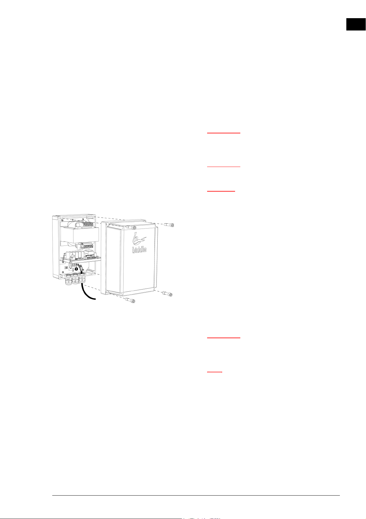
2.5.1 Mounting and connecting the control box
w Make sure that the mains supply group with
which you are working has been turned off.
w The unit must be earthed.
c When installing the unit, use the wiring diagram
supplied.
en
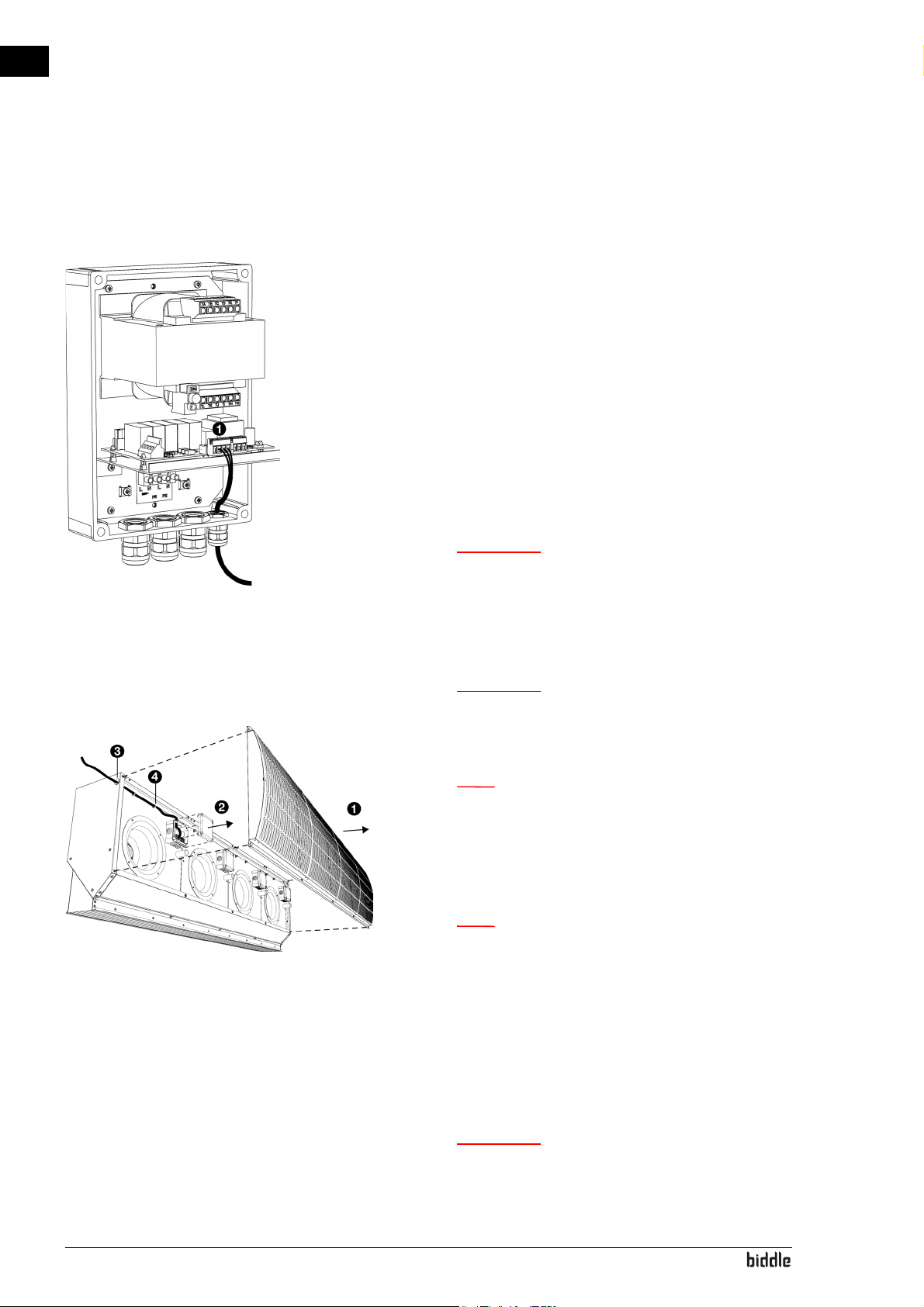
1. Fasten the control box near to the unit.
2. Open the control box:
- Remove the 4 screws.
- Remove the cover.
3. Lay the cable between the control box and the unit.
4. Connect the cable to the control box:
- Fit a cable gland for pull relief.
- Lead the cable into the control box.
- Connect the cable to terminal block X20 1, in accord-
ance with the wiring diagram.
w Connect the earth wire to the screw in the
control box.
n Do not close the control box yet.
Manual version 1.1 (07-04-2016) en-15
Page 16
en
Warning:
Warning:
Note:
Note:
Warning:
INSTALLATION COLD ROOM AIR CURTAIN
Connecting multiple control boxes
A maximum of 8 fans can be connected to 1 control box. This
corresponds with a maximal total unit length of 4m.
In the case of a longer array of multiple control boxes, create a
continuous connection to utilize the same door contact switch
and, if used, the same room thermostat:
1. Lay the cable between the two control boxes.
2. Connect the cable to the control boxes:
- Drill an extra aperture in both control boxes.
- Fit cable glands for pull relief.
- Lead the cable into the control boxes.
- In both control boxes, connect the cable to terminal
block X4 1, in accordance with the wiring diagram.
w Connect the earth wire to the screw in the
control box.
2.5.2 Connecting the control box to the unit
w The unit must be earthed.
1. Remove the inlet grille 1.
n In the event of multiple units, remove the inlet grille
of each unit.
2. Remove the cover of the first terminal box 2, depending
on the side through which you lead the cable into the unit.
n You may lead the cable inward through either end of
the row of units, as you choose.
3. Lead the cable into the unit.
en-16
- In the feed-through hole to be used 3, fit a cable gland
for pull relief.
- Fasten the cable to the edge inside the unit, using the
cable clips 4.
w Do not allow the cable to lie or hang loosely.
Page 17
ISOLAIR MANUAL INSTALLATION
Caution:
Caution:
Warning:
Warning:
4. Make the grommets in the terminal boxes to measure.
c Ensure that the grommets fit so tightly around the
cable that they remain watertight.
5. Lead the cable into the terminal box.
6. Connect the cable to terminal block X30, in accordance
with the wiring diagram.
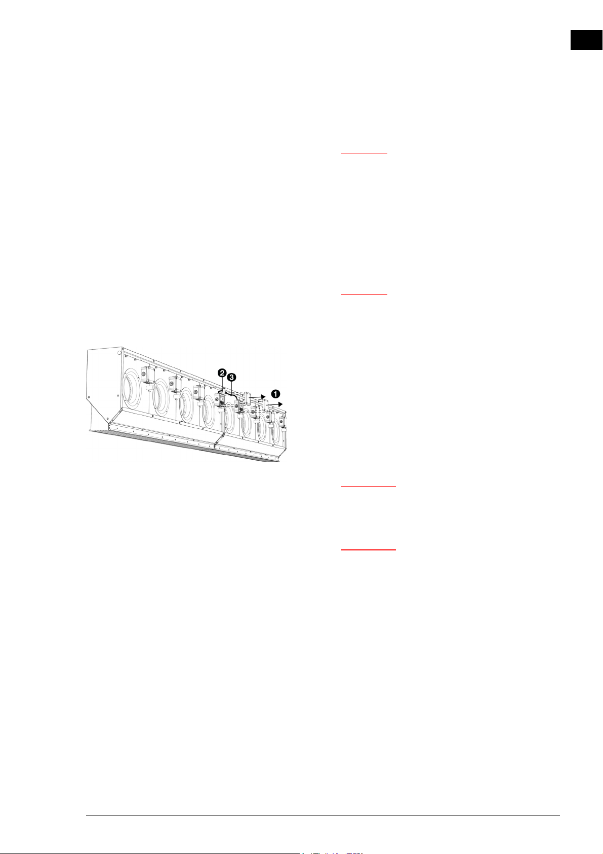
Connecting multiple units
c A maximum of 8 fans can be connected to 1 control
box. This corresponds with a maximal total unit
length of 4m.
en
1. Remove the covers of the two adjoining terminal boxes 1
of both units.
2. Lay the cable between the terminal boxes.
- In the feed-through hole to be used 2, fit a cable gland
for pull relief.
- Fasten the cable to the edge inside the unit, using the
cable clips 3.
w Do not allow the cable to lie or hang loosely.
3. Make the grommets in the terminal boxes to measure.
w Ensure that the grommets fit so tightly
around the cable that they remain watertight.
4. Lead the cable into both terminal boxes.
5. Connect the cable in both units to terminal block X30, in
accordance with the wiring diagram.
Manual version 1.1 (07-04-2016) en-17
Page 18
en
Note:
Note:
INSTALLATION COLD ROOM AIR CURTAIN
2.6 Installing external controls
2.6.1 Installing door contact switch
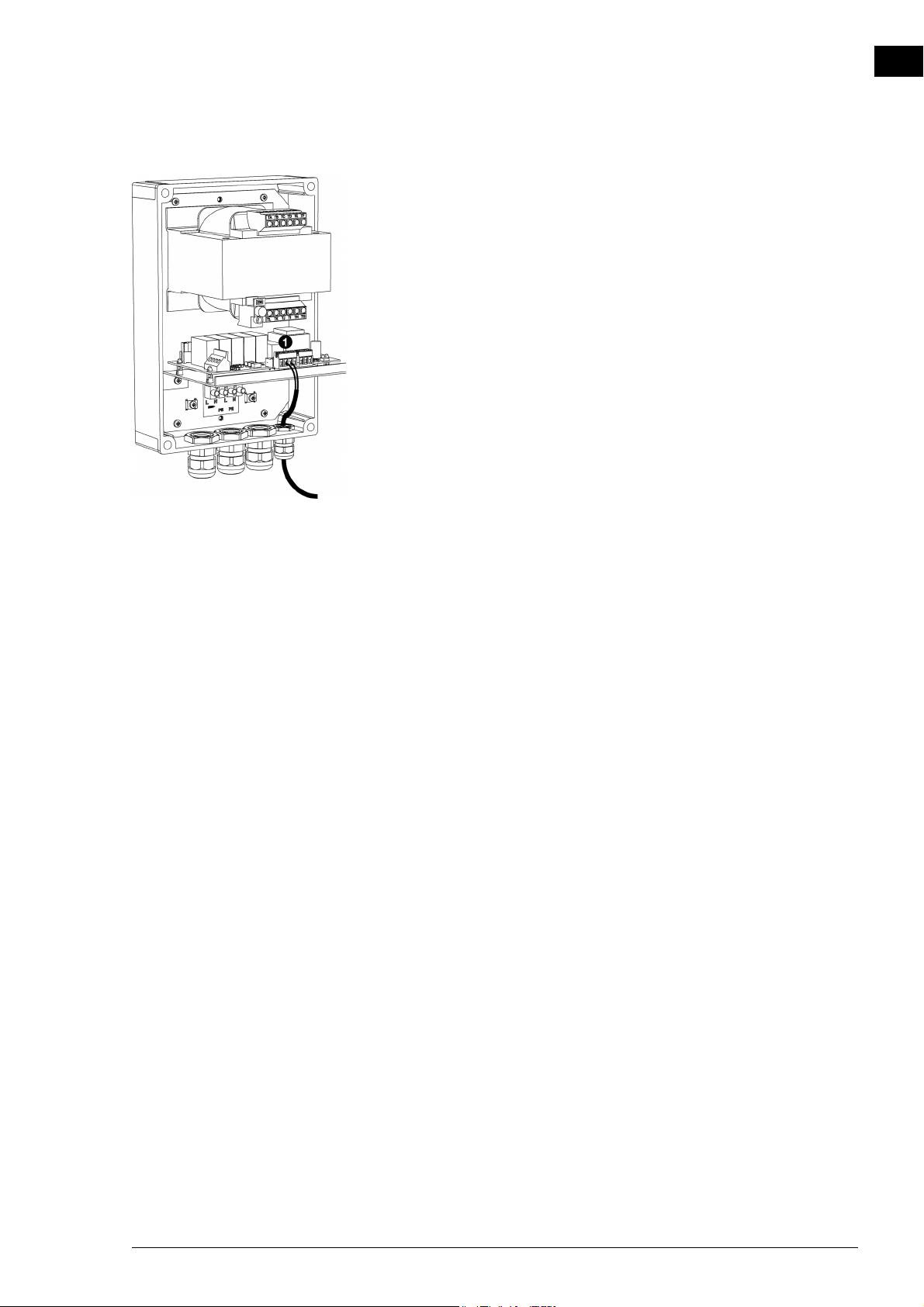
1. Mount the door contact switch to the doorframe.
2. Lay the cable between the door contact switch and the
control box.
3. Connect the cable to the control box:
- Fit a cable gland for pull relief.
- Lead the cable into the control box.
- Connect the cable to terminal block X4 1, in accord-
ance with the wiring diagram.
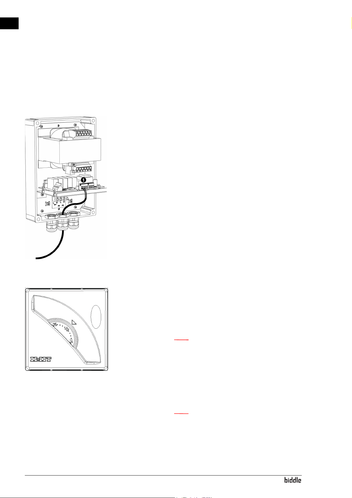
2.6.2 Installing the room thermostat (accessory)
If the temperature difference between the rooms to be separated can vary, a room thermostat can be connected so that
the unit can switch between a low setting and a high setting.
1. Mount the room thermostat in the vicinity of the unit.
n Place the room thermostat in the room where the
unit also hangs.
2. Lay the cable between the room thermostat and the control box.
3. Connect the cable to the room thermostat in accordance
with the wiring diagram.
n Make sure the room thermostat’s adjusting knob is
fixed at the set temperature with the red parameter
jumpers.
en-18
Page 19
ISOLAIR MANUAL INSTALLATION
4. Connect the cable to the control box:
- Drill an extra aperture in the control box.
- Fit a cable gland for pull relief.
- Lead the cable into the control box.
- Connect the cable to terminal block X4 1, in accord-
ance with the wiring diagram.
en
Manual version 1.1 (07-04-2016) en-19
Page 20

en
Warning:
Warning:
Caution:
Note:
INSTALLATION COLD ROOM AIR CURTAIN
2.7 Connecting the mains supply
2.7.1 Special points regarding the mains supply
For all models
w The unit must be earthed.
w The unit must be connected in accordance
with the applicable local requirements.
c For emergencies and maintenance, it must be
possible to render the entire system electrically dead
by means of an isolation switch.
n The control box is equipped with a fuse.
en-20
Page 21
ISOLAIR MANUAL INSTALLATION
Warning:
Warning:
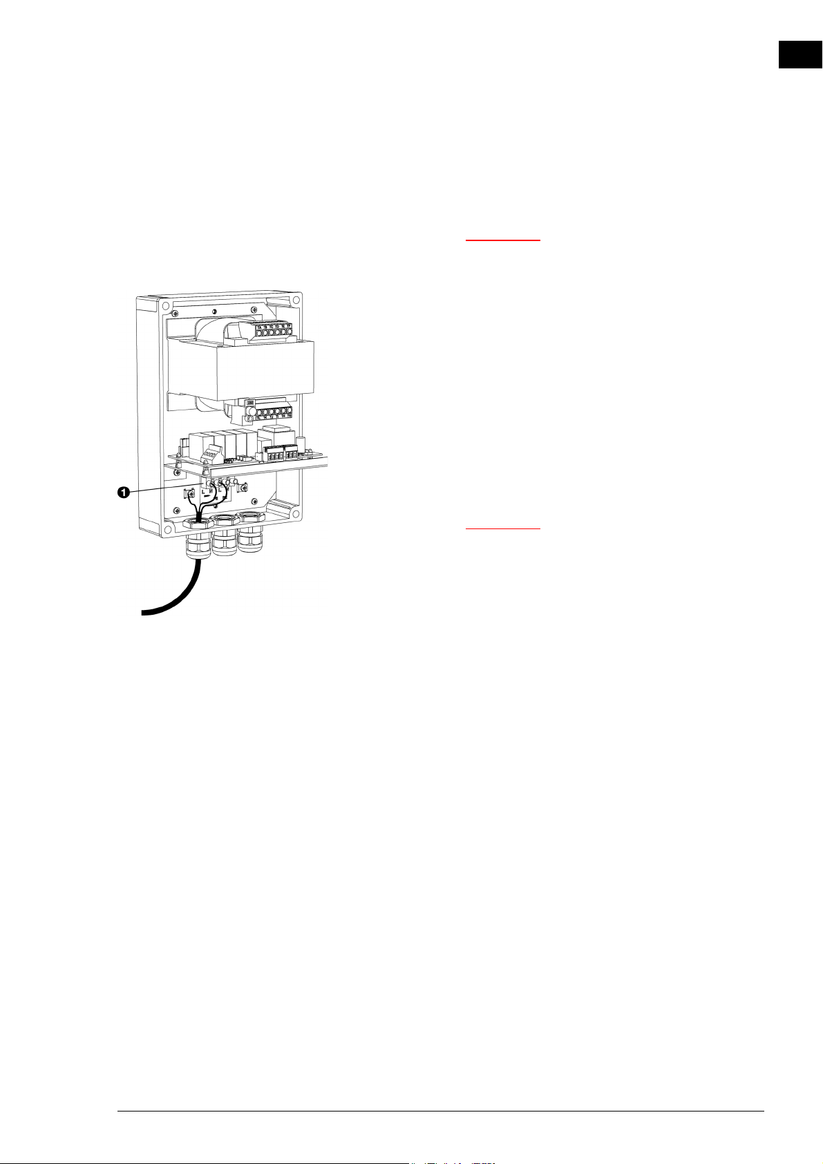
2.7.2 Connecting the mains supply
The mains supply is connected to the control box.
w Make sure that the mains supply is switched
off.
1. Fit an isolation switch between the mains supply and the
control box.
2. Lead the mains power cable between the isolation switch
and the control box.
3. Connect the cable to the control box:
- Fit a cable gland for pull relief.
- Lead the cable into the control box.
- Connect the cable to terminal block X10 1, in accord-
ance with the wiring diagram.
en
w Connect the earth wire to the screw in the
control box.
Manual version 1.1 (07-04-2016) en-21
Page 22
en
INSTALLATION COLD ROOM AIR CURTAIN
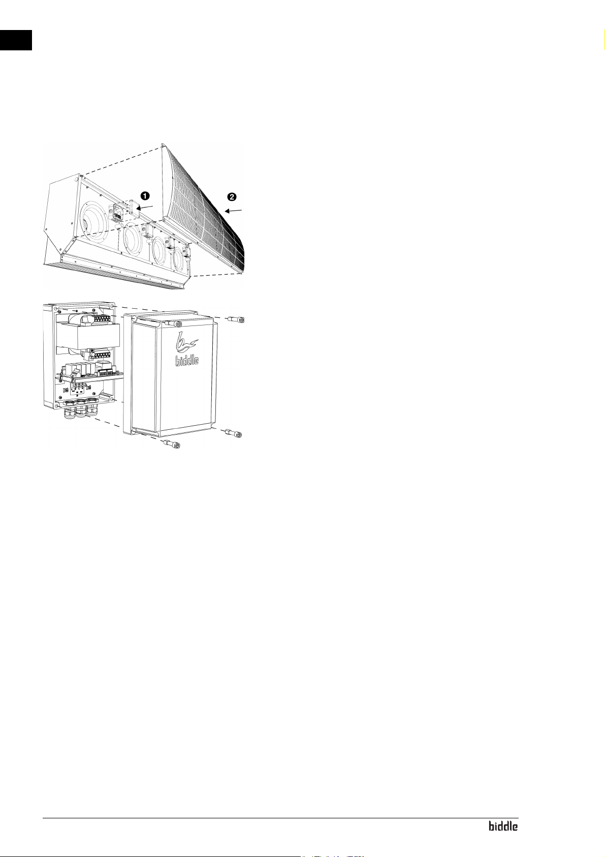
2.8 Finishing the unit
Closing the unit
1. Place the covers back on the terminal boxes 1 in order to
protect the connections against dirt and water.
2. Put the inlet grilles back into place 2.
Closing the control box
1. Put the cover back on the control box.
2. Screw down the cover, using the 4 screws.
2.9 Switching on and checking operation
1. Check the following connections:
- power supply;
- cable between control box and unit(s);
- external control components
2. Switch on the mains supply.
3. Check that the fans are running.
en-22
Page 23

3. . Operation
3.1 General
The unit is set up for the situation concerned at the time of
installation. Further control is not necessary during use.
If the unit is not working properly, consult chapter 4Errors.
en
Manual version 1.1 (07-04-2016) en-23
Page 24
en
4. . Errors
4.1 Resolving simple problems
If you suspect an error, first try to resolve the problem, using
the table below. You do not have to be an expert for this.
If this fails to resolve the problem, there may be a fault; in that
case, alert the installer.
P
ROBLEM PROBABLE CAUSE WHAT TO DO
The unit does not work. The unit has not been switched on. Turn the unit on.
The unit has no power supply. Check the mains supply:
•isolation switch,
• unit has power.
The unit is not discharging much air.
(The draught)
The unit has been switched off by
external control components.
The inlet and/or discharge section
becomes blocked.
The unit is not set properly. Consult your advisor.
Check external control components, if present:
• door contact switch
Remove obstacles to the inlet and
discharge section.
en-24
Page 25

5. . Maintenance
Warning:
5.1 Cleaning the unit
You can clean the inside and the outside of the unit with water
and household cleaning products. Do not use any solvents.
The fans too can be cleaned with water.
en
5.2 Scheduled maintenance
w No water under high pressure may be sprayed
onto the fans or the terminal boxes.
5.2.1 Monthly maintenance
With all units:
• Check the fans for dust and other dirt; if necessary, clean.
• Check that all fans work.
• Check the discharge section for pollution/dirt and/or
blockage; if necessary, clean.
See also:
5.1 "Cleaning the unit" on page 25
5.2.2 Annual maintenance
With all units:
• Carry out all monthly checks.
• Check the cabling between the terminal boxes in the units
and the control unit.
• Inspect the casing, the suspension or mounting structure,
and the securing of each unit.
• Check whether the fans are firmly attached and are not
running out of true; if necessary, fasten them again.
Manual version 1.1 (07-04-2016) en-25
Page 26
en
Warning:
Warning:
Warning:
Note:
6. . Service
6.1 Safety instructions
w Servicing activities may only be carried out by
personnel who are technically qualified to do
so.
6.2 Replacing a fan box
w Before you begin: read the safety instructions.
See also:
1.5 "Safety instructions" on page 8
w Shut off the mains supply.
n In order to remove one of the outermost fan boxes,
the adjacent fan box must first be removed.
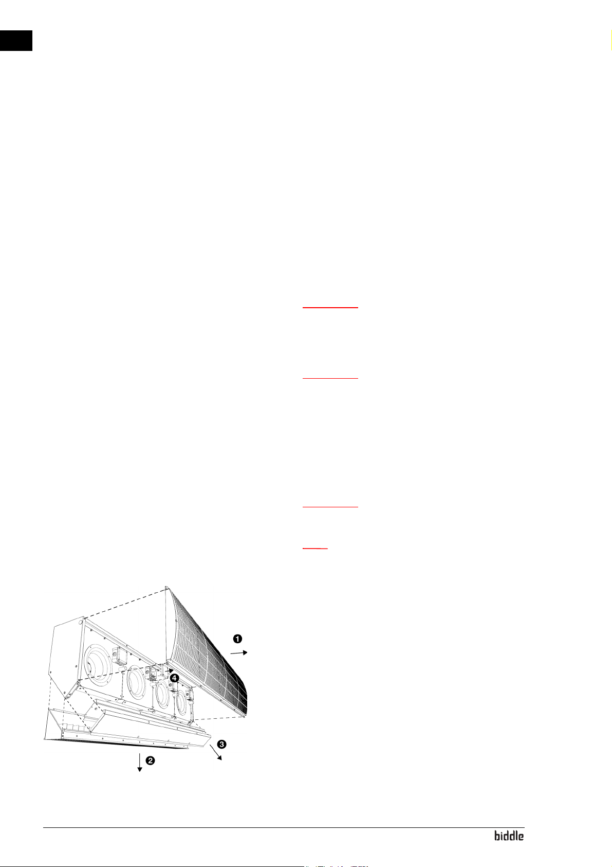
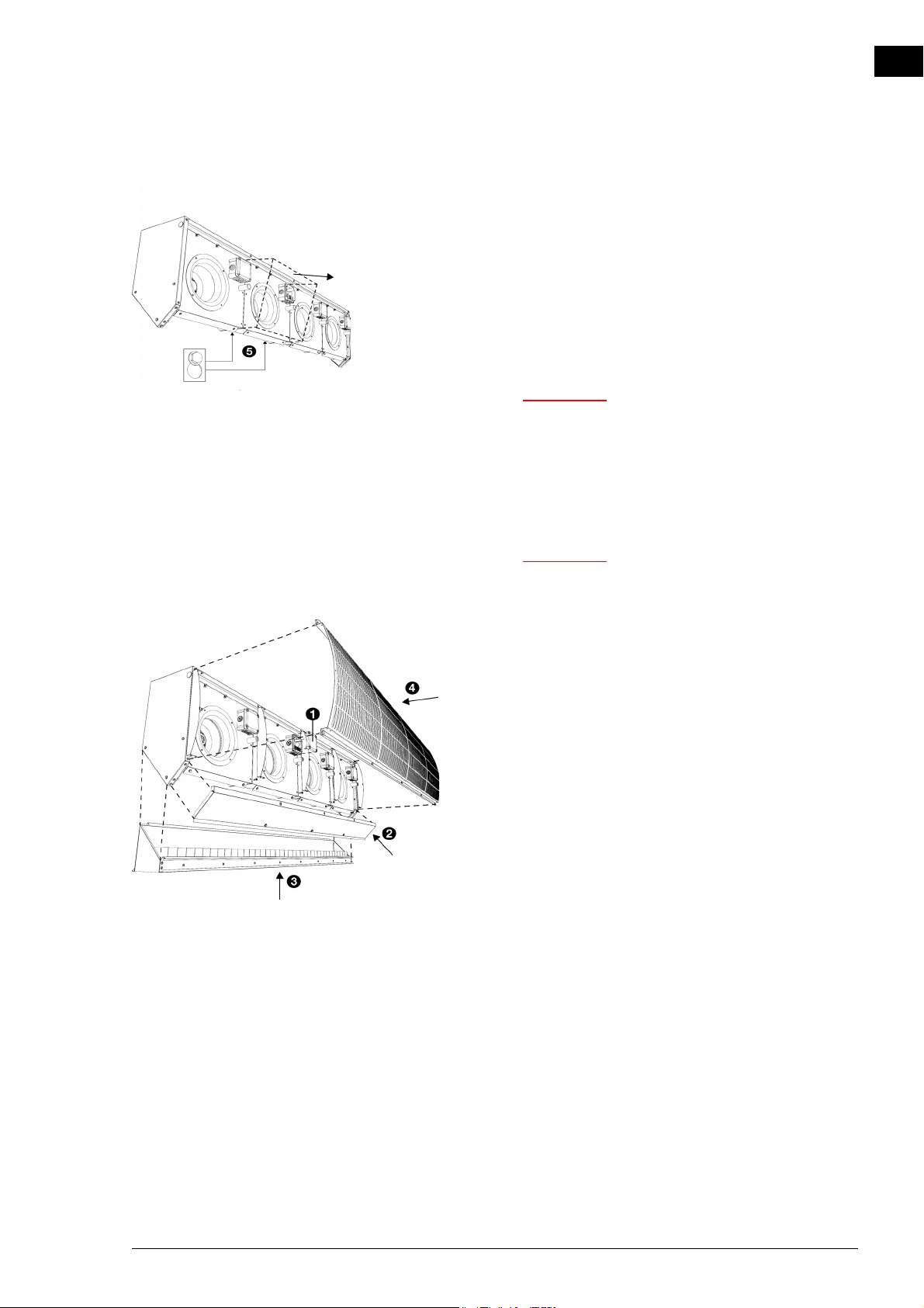
1. Open the unit:
- Remove the inlet grille 1.
- Remove the discharge grille 2.
- Remove the base plates 3.
2. Disconnect the fan box that is to be removed:
en-26
- Remove the cover from the terminal box 4.
- Disconnect the wiring
Page 27
ISOLAIR MANUAL SERVICE
Warning:
Warning:
3. Unscrew the fan box 5.
4. Lift the fan box out of the unit.
5. Position the new fan box.
6. Secure the new fan box with screws.
7. Connect the new fan box:
- Make the grommets in the terminal boxes to measure.
w Ensure that the grommets fit so tightly
around the cable that they remain watertight.
- Lead the cable into the terminal box.
- Connect the cables to the terminal block in accord-
ance with the wiring diagram.
en
w Keep the length of the cables as short as
possible.
8. Close the unit:
- Place the covers back on the terminal box 1, in order
to protect the connections against dirt and water.
- Fasten the base plates 2.
- Fasten the discharge grille 3.
- Fasten the inlet grille 4.
9. Switch on the mains supply.
Manual version 1.1 (07-04-2016) en-27
Page 28
en
Note:
SERVICE COLD ROOM AIR CURTAIN
6.3 Fuses
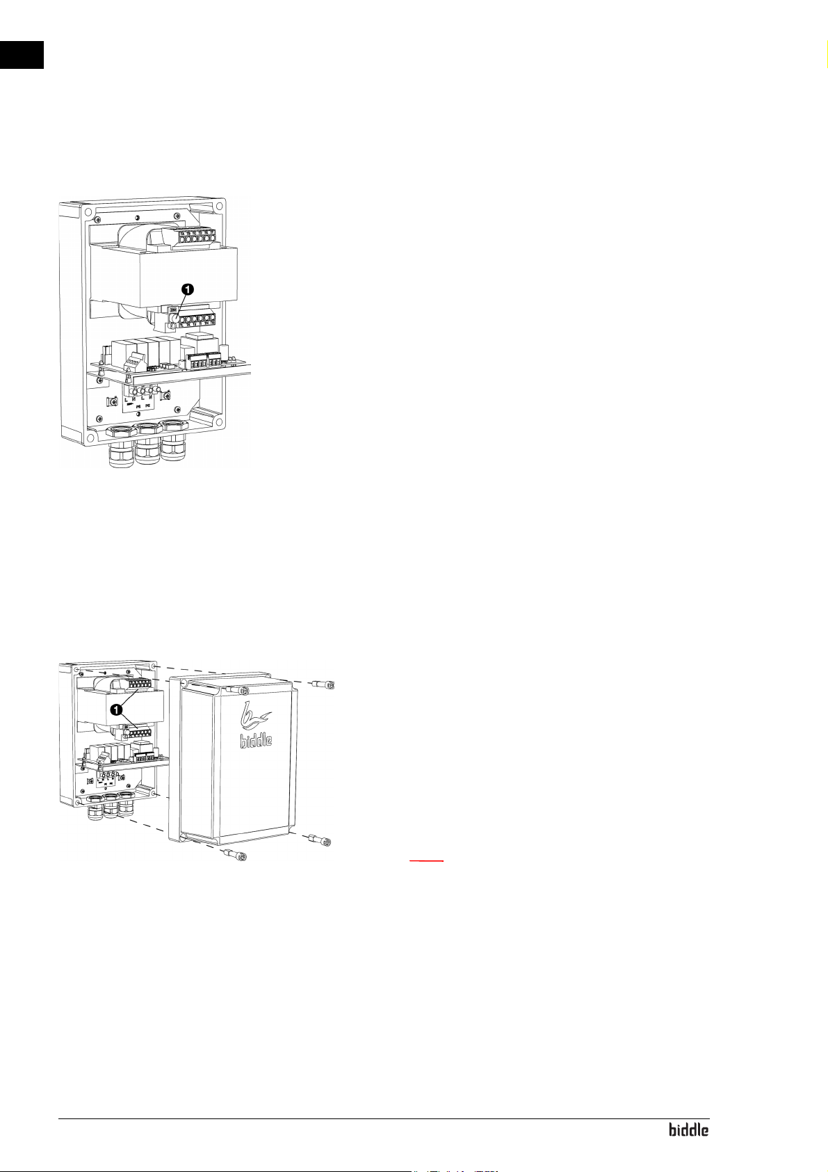
The control box is equipped with a fuse 1.
The value is indicated on the fuse.
6.4 Adjusting modes
6.4.1 Adjusting branches
The unit is configured for the situation for which it was purchased. If the situation changes, the modes can be adjusted
accordingly.
1. Consult your Biddle advisor about the optimum modes for
your specific situation.
2. Open the control box.
3. Connect the wire marked number 2 to the branch 1 that
belongs with the low mode.
4. Connect the wire marked number 3 to the branch that
belongs with the high mode.
n If there is already a wire in the branch, move this to
another branch of your choice.
en-28
Page 29
ISOLAIR MANUAL SERVICE
Note:
Note:
Note:
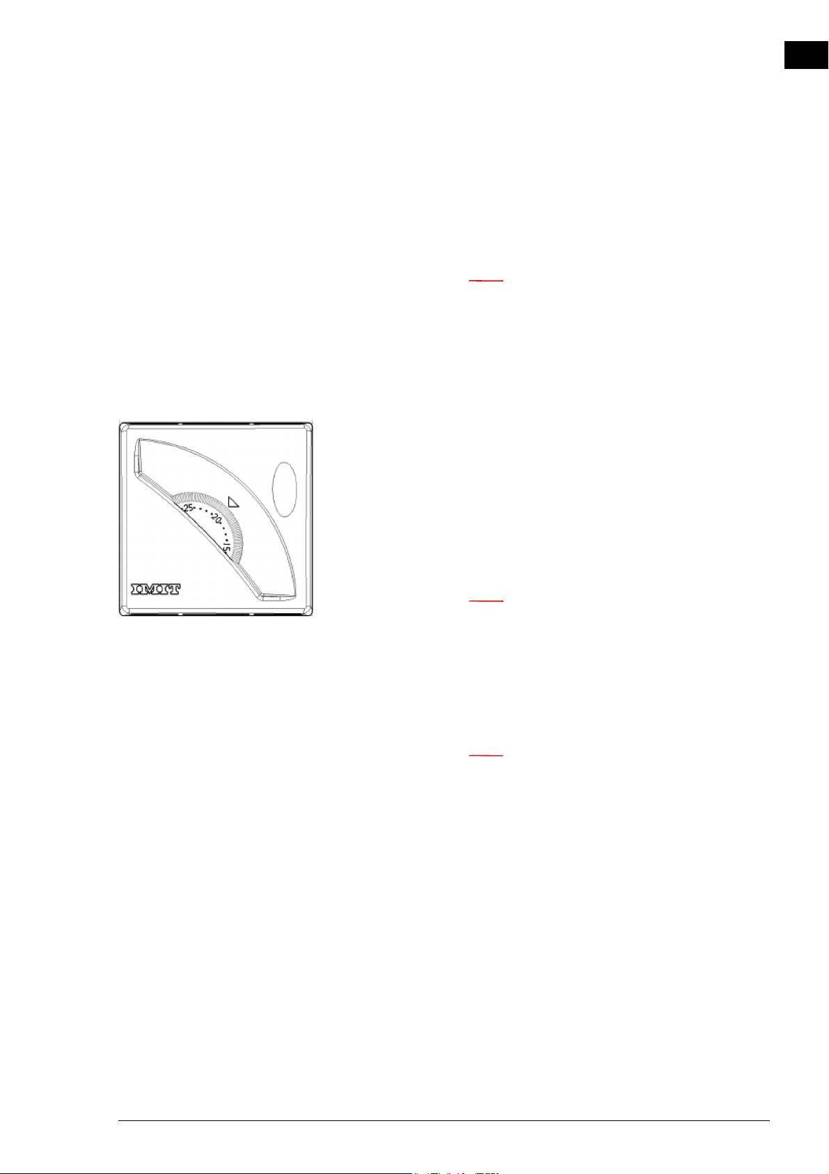
6.4.2 Adjusting room thermostat
The room thermostat determines at which temperature of the
front hall the unit will switch between the low mode and the
high mode.
n If the temperature in the front hall is lower than the
set temperature, the unit will operate in the low
mode.
If the temperature in the front hall is higher than the
set temperature, the unit will operate in the high
mode.
1. Consult your Biddle advisor about the optimum setting of
the room thermostat for your specific situation.
en
2. Open the room thermostat.
3. Find the recommended temperature
on the white outer edge of the knob and turn the knob so
that the temperature is at the boundary pin.
n Use the small white numbers on the outer edge, not
the big gray numbers.
4. Fix the button by placing the red jumpers to the immediate left and right of the recommended temperature.
5. Close the room thermostat.
n Make sure the recommended temperature now is at
the arrow.
Manual version 1.1 (07-04-2016) en-29
Page 30

SERVICE COLD ROOM AIR CURTAIN
en-30enManual version 1.1 (07-04-2016) en-31
Page 31

7. . Dismantling
The dismantling of the installation and the handling of the
coolant, oil and other components must be carried out by a
qualified fitter in accordance with the relevant local and
national legislation and regulations.
Pursuant to EU legislation, used electrical and electronic appliances must be collected for recycling. By ensuring that this
product is disposed of in the correct manner, you are helping
to prevent potential negative consequences for the environment and public health. For more information about this,
please contact your supplier or the relevant government
authority.
en
Page 32

en
DISMANTLING COLD ROOM AIR CURTAIN
en-32
Page 33

8. . Addresses
If you have any comments or queries relating to this product,
please do not hesitate to contact your Biddle branch.
en
Biddle bv
P. O. B o x 1 5
9288 ZG Kootstertille
The Netherlands
Biddle nv
Battelsesteenweg 455 B
2800 Malines
Belgium
Biddle Air Systems Ltd.
St. Mary’s Road, Nuneaton
Warwickshire CV11 5AU
United Kingdom
Biddle GmbH
Emil-Hoffmann-Straße 55-59
50996 Cologne
Germany
Biddle France
21 Allée des Vendanges
77183 Croissy Beaubourg
France
Manual version 1.1 (07-04-2016) en-33
Page 34

en
ADDRESSES COLD ROOM AIR CURTAIN
en-34
Page 35

ISOLAIR MANUAL
. . . Keywords
en
A
accessories . . . . . . . . . . . . . . . . . . . . . . . . . 7
addresses . . . . . . . . . . . . . . . . . . . . . . . . . 33
adjusting modes . . . . . . . . . . . . . . . . . . . . 28
application limits. . . . . . . . . . . . . . . . . . . . . 6
C
CE declaration . . . . . . . . . . . . . . . . . . . . . . 6
cleaning . . . . . . . . . . . . . . . . . . . . . . . . . . . 25
connecting control boxes. . . . . . . . . . . . . 16
connecting units . . . . . . . . . . . . . . . . . . . . 17
control box. . . . . . . . . . . . . . . . . . . . . . . . 15
D
delivery inspection . . . . . . . . . . . . . . . . . . . 9
designations . . . . . . . . . . . . . . . . . . . . . . . . 3
determine location . . . . . . . . . . . . . . . . . . 11
dismantling . . . . . . . . . . . . . . . . . . . . . . . . 31
door contact switch . . . . . . . . . . . . . . . . . 18
E
errors . . . . . . . . . . . . . . . . . . . . . . . . . . . . 24
F
O
operation . . . . . . . . . . . . . . . . . . . . . . . 5, 23
P
power . . . . . . . . . . . . . . . . . . . . . . . . . . . . . 6
power supply voltage . . . . . . . . . . . . . . . . . 6
problems. . . . . . . . . . . . . . . . . . . . . . . . . . 24
product series . . . . . . . . . . . . . . . . . . . . . . 5
R
replacing fan . . . . . . . . . . . . . . . . . . . . . . . 26
room thermostat . . . . . . . . . . . . . . . . . . . 18
S
safety instructions
installation . . . . . . . . . . . . . . . . . . . 8, 9
maintenance . . . . . . . . . . . . . . . . . . . . 8
service . . . . . . . . . . . . . . . . . . . . . 8, 26
usage. . . . . . . . . . . . . . . . . . . . . . . . . . 8
service . . . . . . . . . . . . . . . . . . . . . . . . . . . 26
side shield . . . . . . . . . . . . . . . . . . . . . . . . . 14
suspension . . . . . . . . . . . . . . . . . . . . . 11, 12
switching ON . . . . . . . . . . . . . . . . . . . . . . 22
symbols. . . . . . . . . . . . . . . . . . . . . . . . . . 3, 4
finishing the unit . . . . . . . . . . . . . . . . . . . . 22
fuse . . . . . . . . . . . . . . . . . . . . . . . . . . . . . . 28
I
installation. . . . . . . . . . . . . . . . . . . . . . . . . . 9
external controls . . . . . . . . . . . . . . . 18
L
length . . . . . . . . . . . . . . . . . . . . . . . . . . . . . 5
T
The . . . . . . . . . . . . . . . . . . . . . . . . . . . . . . . 5
type code . . . . . . . . . . . . . . . . . . . . . . . . . . 5
type designation . . . . . . . . . . . . . . . . . . . . . 5
type plate . . . . . . . . . . . . . . . . . . . . . . . . . . 6
typecode. . . . . . . . . . . . . . . . . . . . . . . . . . . 5
W
wiring diagram . . . . . . . . . . . . . . . . . . . . . . 4
working method. . . . . . . . . . . . . . . . . . . . 10
M
mains supply . . . . . . . . . . . . . . . . . . . . . . . 20
maintenance . . . . . . . . . . . . . . . . . . . . . . . 25
models. . . . . . . . . . . . . . . . . . . . . . . . . . . . . 5
modifications. . . . . . . . . . . . . . . . . . . . . . . . 6
Manual version 1.1 (07-04-2016) en-35
Page 36

en
Copyright and Trademarks
All information and drawings contained in this manual are the property of Biddle and may not be used (other than
for the purpose of unit operation), photocopied, reproduced, translated and/or communicated to third parties
without prior written permission from Biddle.
The name Biddle is a registered trademark of Biddle bv.
Warranty and liability
For the warranty and liability provisions and terms, please refer to the terms & conditions of sale and supply.
At all times, Biddle shall not be held liable for consequential damages.
Liability as regards the manual
Although great care has been taken to ensure the correct and, where necessary, complete description of the
relevant components, Biddle shall not be held liable for damages as a consequence of errors and/or imperfections
in this manual.
Biddle reserves the right to alter the specifications as mentioned in this manual.
Should you nevertheless discover any errors or ambiguities in the manual, we shall be glad to learn that from you.
It helps us to improve the documentation still further.
For more information
If you have any comments or queries relating to this product, please do not hesitate to contact Biddle. You will find
the contact information for your Biddle branch in chapter 8 Addresses.
Biddle bv
P.O. Box 15
9288 ZG Kootstertille
The Netherlands
Name and telephone number of installer:
 Loading...