

Page 1

®
Vocia
VA-2060, VA-2060e,
VA-4030, VA-4030e
Manual
Biamp Systems, 9300 SW Gemini Drive, Beaverton, Oregon 97008 U.S.A. (503) 641-7287 www.biamp.com
Page 2
IMPORTANT SAFETY INSTRUCTIONS
13) Unplug this apparatus during
Explanation of safety related
1) Read these instructions.
2) Keep these instructions.
3) Heed all warnings.
4) Follow all instructions.
WARNING - To reduce the risk of fire or
electric shock, do not expose this
apparatus to rain or moisture.
The apparatus shall not be exposed to
dripping or splashing and no objects filled
with liquids, such as vases, shall be
placed on the apparatus.
5) Do not use this apparatus near water.
6) Clean only with dry cloth.
7) Do not block any ventilation openings.
Install product in accordance with the
manufacturer’s instructions.
8) Do not install near any heat sources
such as radiators, heat registers, stoves,
or other apparatus (including amplifiers)
that produce heat.
CAUTION – Installation of the apparatus
should be made by a qualified installation
person and should conform to all
applicable local codes.
Modifications and optional equipment
information referenced in this manual is
for use by qualified installation and
service personnel only.
WARNING – Class I Safety Grounding
This apparatus employs Class I Safety
Grounding and must be connected to a
MAINS socket with a protective eathing
connection.
Disconnect Device - The MAINS plug is
used to disconnect MAINS power and
must remain readily operable.
9) Do not defeat the safety purpose of
the grounding-type plug. A grounding
type plug has two blades and a third
grounding prong. The third prong is
provided for your safety. If the provided
plug does not fit into your outlet, consult
an electrician for replacement of the
obsolete outlet.
10) Protect the power cord from being
walked on or pinched particularly at
plugs, convenience receptacles, and the
point where they exit from the apparatus.
11) Only use attachments/accessories
specified by the manufacturer.
12) Use only when secured or supported
by equipment rack, cart or table designed
to provide adequate mechanical strength,
heat dissipation and securement to the
building structure.
When a cart is used, use
caution when moving the
cart / apparatus combination
to avoid injury from tip-over.
lightning storms or when unused for long
periods of time.
14) Refer all servicing to qualified service
personnel. Servicing is required when the
apparatus has been damaged in any way,
such as power-supply cord or plug is
damaged, liquid has been spilled or
objects have fallen into the apparatus,
the apparatus has been exposed to rain
or moisture, does not operate normally,
or has been dropped.
symbols which appear on the outside
of the apparatus.
Product labeling and the operation
manual may use the internationally
recognized symbols defined below to note
safety messages.
Lightning Bolt: Hazardous
Live voltages present when
this unit is in operation. Do
not touch terminals marked
with this symbol while the unit
is connected to live power.
Exclamation Point: Replace
components (i.e. fuses) only
with the values specified by
the manufacturer. Failure to
do so will compromise safe
operation of this unit.
Page 3

TABLE OF CONTENTS
VOCIA AMPLIFIER ........................................................................................3
VA-2060, VA-2060e, VA-4030 and VA-4030e ....................................................................3
Features ................................................................................................3
FRONT PANEL ...........................................................................................4
System Indicators .........................................................................................4
Amplier Chassis Indicators .................................................................................4
Amp Channel Indicators ....................................................................................5
Front Panel View .........................................................................................6
VA-2060 .................................................................................................6
VA-2060e ................................................................................................6
VA-4030 .................................................................................................6
VA-4030e ................................................................................................6
REAR PANEL ............................................................................................7
Conventions ..............................................................................................7
AC Power Socket .........................................................................................7
Auxiliary Power ...........................................................................................7
Network Connections ......................................................................................7
Device ID switches ........................................................................................8
Analog Audio Inputs with Phantom Power Option .................................................................8
Page Active Relay .........................................................................................8
Amplier Output Connections ..............................................................................9
Transformer Load Selection .................................................................................9
Speaker Connection .......................................................................................9
Rated Load Table .........................................................................................9
Output Fault Detection ......................................................................................9
FAILOVER MODES ......................................................................................10
Device-to-Device Failover ..................................................................................10
Channel-to-Channel Failover ................................................................................11
SPECIFICATIONS ........................................................................................12
Vocia Amplier 2060 / 2060e / 4030 / 4030e ...................................................................12
BLOCK DIAGRAM .......................................................................................13
CURRENT DRAW AND HEAT OUTPUT ......................................................................14
WARRANTY ............................................................................................15
EU DECLARATION .......................................................................................16
EU ROHS COMPLIANT ...................................................................................17
Page 4

VOCIA AMPLIFIERS VA-2060, VA-2060e, VA-4030, VA-4030e
The VA-2060, VA-2060e, VA-4030 and VA-4030e are digital networked multi-channel audio ampliers designed for use in Vocia systems.
All models are CobraNet® enabled and feature either two or four channels of amplication, with on-board DSP. Channel-to-channel or
device-to-device failover may be user congured. Each amplier channel has user selectable support for 4 or 8Ω operation or Constant
Voltage operation of 25, 70 or 100 Volts. The on-board DSP provides comprehensive xed-chain digital signal processing within the device,
including volume control, ducking, equalization, compressor/limiting, speaker crossover, delay and output gain. Locally stored audio messages are retained in non-volatile memory within the amplier. Intuitive software provides audio system design via PC computer. Two RJ45
connectors on the rear panel of the amplier provide redundant connectivity to control data and audio over a single Ethernet cable. The
VA-2060e and VA-4030e models have the ability to be powered via dual 24V connections in addition to the AC mains power supply, as well
as balanced mic/line inputs to be used as a local background input source for the output channel associated with the Input.
SET UP AND USE
FEATURES
• Amplier outputs transformer coupled to support Low
Impedance or Constant Voltage loads. User selectable
via rear panel switch:
- Low impedance: 4 or 8Ω OR
- Constant Voltage: 25V, 70V or 100V
• Output Power:
- VA-4030(e): 4 Channel 30W RMS per channel
- VA-2060(e): 2 channel 60W RMS per channel
• Failover capability between channels and ampliers
• Locally stored audio messages are retained in non-volatile
memory within the amplier.
• LED Indication:
- Amplier and card failure
- Clip present
- Fan stuck rotor fault
- Heat sink temperature fault
- Signal Peak
- Signal present
• Software Monitoring Features:
- Amplier failure
- Excessive clipping
- Fan stuck rotor
- Temperature fault
- Peak present
- Amplier overload
- Short to ground on output
• Software-congurable signal processing including volume
control, lters, compressor/limiting, delay, speaker equalization
and output sensitivity
• CobraNet
®
audio/control with dynamic use of available
bundles over single Ethernet cable
• Dual Ethernet ports for redundancy
• Heavy duty removable terminal block connectors for speaker
line connections
• Rotary switches for device identication
• EN 54-16 certication pending, CE marked, UL listed,
RoHS compliant
• Covered by Biamp Systems’ warranty
The Vocia software provides the interface for conguring and programming the VA-4030(e) and VA-2060(e) ampliers. The information
supplied by this manual relates to hardware installation, physical connections and device and channel failover concerns. For more details
on software setup, please consult the Vocia Software Help File.
3
Page 5
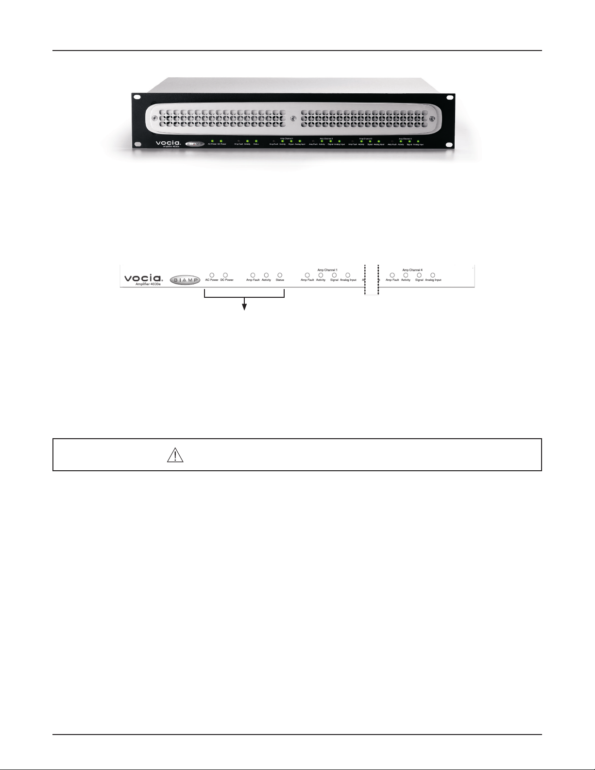
VOCIA AMPLIFIERS VA-2060, VA-2060e, VA-4030, VA-4030e FRONT PANEL
System Indicators
The LED indicators on the front panel of the amplier provide information and operational status of the amplier and its associated output
and input channels. LED layout and features vary between amplier models. LEDs are grouped to show chassis and amplier channel
status indication. Please see the Front Panel View section for details on the different congurations between the various amplier models.
Chassis Indicators
Amplier Chassis Indicators
These indicators relate to the entire amplier unit (chassis):
AC power is a green LED indicator. This will illuminate when a AC Mains supply is applied to the unit.
DC Power (VA-2060e and VA-4030e models only) is a green LED indicator. This illuminates when an auxiliary DC supply is applied to the
unit via either or both 24V Auxiliary power inputs.
Refer to the caution in the Rear Panel Auxiliary Power section.
Amp Fault is a yellow LED that illuminates when a chassis fault has occurred. There are two types of chassis faults that can be reported,
depending on the severity of the problem. Flashing yellow indicates a Warning, which means that some aspect of the amplier chassis is
not performing within normal specication. Audio may still be passing, but if the condition causing the Warning is not corrected, chassis
failure may occur. Solid yellow indicates a fault, which means that some aspect of the amplier chassis has failed and audio may no longer
be passing through the device. Use Vocia software to determine the specic type of chassis warning or fault that has occurred.
Activity is a tri-color LED that illuminates to show the conguration status of the device. If the LED is dark, the chassis has failed to
boot or there is some other kind of fault. A solid green LED indicates that the unit is congured. A ashing yellow LED indicates the unit is
active but not congured. A solid yellow LED indicates that the unit is congured and in standby. Standby only occurs when a unit has
been designated as a redundant device when Device Failover is enabled.
Status is a tri-color LED that indicates the health of the amplier hardware. A green LED indicates the unit powered up normally. A ashing
yellow LED is shown briey during the power-up self test and should turn solid green upon successful start. A red LED indicates the unit
experienced a problem during the power-up self test.
4
Page 6

VOCIA AMPLIFIERS VA-2060, VA-2060e, VA-4030, VA-4030e FRONT PANEL
Channel Indicators
Amp Channel Indicators
These indicators relate to each amplier channel:
Amp Fault is a yellow LED that illuminates when a channel fault has occurred. Two types of channel faults can be reported depending on
the severity of the problem. Flashing yellow indicates a Warning, which means that some aspect of the amplier module is not performing
within normal specication. Audio may still be passing, but if the condition causing the Warning is not corrected, channel failure may occur.
Solid yellow indicates a fault, which means that some aspect of the amplier module has failed and audio is no longer passing on that
channel. Use Vocia software to determine the specic type of channel warning or fault that has occurred.
Activity is a two-color LED that illuminates green when that channel is congured and actively passing audio and yellow when that channel is
congured and in standby. Standby only occurs when a channel has been designated as redundant channel in a failover conguration.
Signal is a tri-color LED that indicates audio signal presence on the amplier channel. Green indicates the audio signal level is between
-36 dBFS and -6 dBFS, yellow indicates a signal level between -6dBFS and -2 dBFS and red indicates clipping (above -2dBFS).
Analog Input (VA-2060e and VA-4030e models only) is a tri-color LED that indicates audio signal presence on the amplier analog Input
channel. Green indicates the audio signal level is between -48 dBFS and -18 dBFS, yellow indicates a signal level between -18 dBFS and
-2 dBFS and red indicates clipping (above -2dBFS).
5
Page 7

VOCIA AMPLIFIERS VA-2060, VA-2060e, VA-4030, VA-4030e FRONT PANEL VIEW
VA-2060
VA-2060e
VA-4030
VA-4030e
6
Page 8

Rear Panel
VOCIA AMPLIFIERS VA-2060, VA-2060e, VA-4030, VA-4030e REAR PANEL
BIAMP SYSTEMS
assembled in the USA
www.biamp.com
100-240V~ 50/60Hz
60 Watts
Auxiliary Power
24V DC
24V 0V 24V 0V
10
N24138
0832-CPD-1401
GRN: Link / Active
YEL: In Use / Conductor
12
CobraNet
®
52SJ
Pri. Sec.
4
-+-
Device ID
+
LSBMSB
Analog Inputs
3 2 1
+-+
-
Page Active Relays
C NC NO C NC NO C NC NO C NC NO
4 3 2 1
Failover
CAUTION
RISK OF ELECTRICAL SHOCK.
DO NOT OPEN.
25V
8Ω
70V
4Ω
+ -+ -+ -+ -+ -+ -+ -+
2 1
8Ω
100V 4Ω
-
4 3 2 1
25V
70V
100V 4Ω
Class 3 wiring:
100V setting
Class 2 wiring:
4Ω, 8Ω, 25V and
Outputs
Load
Select
70V setting
Model VA-4030e
25V
8Ω
70V
100V 4Ω
25V
8Ω
70V
100V
Conventions
All numbered audio, relay and power connectors on the rear panel of the amplier are congured with the lowest output or input on the
right of the connector as viewed from the rear of the unit.
AC Power Socket
Provides for connection of the appropriate power cord. Each amplier uses a switch mode power supply that has an operating voltage
of 100-240V at 50/60 Hz.
Auxiliary Power: Only available with VA-2060e and VA-4030e ampliers.
Caution: Due to potential energy hazard, connections to the Auxiliary Power 24V DC inputs must be
made by a qualied electrician or other qualied person as required to conform with all local codes.
This connection allows dual 24V DC power inputs to be used. Dual 24V DC supply capability allows the amplier to
meet standards that call for redundant power supplies. The DC supply must be wired into both power supply inputs,
either from redundant supplies or from a single supply wired in parallel to the two inputs. If 24V is not supplied to both inputs, a loss-ofsupply fault will be reported. If a VA-4030e or VA-2060e amplier is required to operate without a 24V supply, the Auxiliary supply fault
monitoring must be disabled in Vocia software. A loss of supply fault is indicated via the Vocia software and by a blinking yellow Amp Fault
indicator on the front panel of the affected device. The power supplies used for the amplier must meet the voltage range and power requirements detailed in the specications table below. Local standards, norms or codes may require the use of certied power supplies and
may require observance of minimum on-battery running times both for standby and maximum power conditions. Note that dual redundant
power supplies must each independently meet the total power requirements of the amplier.
The pluggable terminal blocks provided will accommodate wire sizes from 12-18 AWG. External over-current protection must be provided,
according to the current carrying capacity of the connecting wires, and in no case greater than 30 Amps. Do not ground or connect to chassis
either the positive or negative Auxiliary Power connections. The Auxiliary power must be oating with respect to ground.
Network Connections
The amplier is a CobraNet device. A Primary and Secondary CobraNet connection is provided for this. All
CobraNet routing and bundle assignments are processed by the Vocia devices locally. Vocia makes dynamic use
of available bundles in CobraNet. A 100Base-T Ethernet switch (not repeater hub) is required when networking
multiple units. CobraNet utilizes standard CAT5, CAT5e, CAT6 or CAT7 cabling, which has a specied maximum length of 328 feet (100
meters). Additional Ethernet switches, or switches that provide ber-optic interface, can be used to extend the physical distance between
units within a network. Please note that CobraNet limits network extensions to seven hops (one-way transmissions) within a network. The
CobraNet network connection is congured with the primary connector on the left and the secondary (redundant) connector on the right.
The primary and secondary CobraNet ports are provided to facilitate connection redundancy. Each connector provides two LEDs that
indicate Ethernet link and network activity.
7
Page 9

VOCIA AMPLIFIERS VA-2060, VA-2060e, VA-4030, VA-4030e REAR PANEL
Table 1. CobraNet LED indication
Left LED Right LED Description
None None No data connectivity or CobraNet activity
None Green Link established
Flashing yellow Green Link established and CobraNet activity detected; unit acting as a CobraNet performer
Flashing yellow Flashing green Link established and CobraNet activity detected; unit acting as a CobraNet conductor
Flashing yellow None CobraNet fault; check cabling and conguration for errors
Device ID switches
The rotary ID switches are located on the back of the amplier and give the unit a unique Device ID. The switches are in
hexadecimal format. All Vocia units of the same type must have a unique Device ID to function properly within a Vocia Paging
World (for instance, it is not possible to have two Vocia devices of the same type with the same Device ID of hex 07). Note that
VA-4030 and VA-4030e units represent one device type, while VA-2060 and VA-2060e units represent another device type.
As an example, to assign a Device ID of hex 07, leave the MSB switch on 0 and turn the LSB switch to 7. To create an ID of hex B7, turn
the MSB switch to B and turn the LSB switch to 7. Device ID switches should be set using a 0.1 inch (2.5mm) to 0.12 inch (3.0mm) at
blade screwdriver. More information on setting IDs and the hexadecimal numbering scheme used can be found in the Vocia Software
Help File.
Analog Audio Inputs with Phantom Power Option
For the VA-2060e and VA-4030e, each amplier channel has analog inputs that allow a local balanced
microphone or line level background source to be delivered to the amplier channel associated with
that input. Two such inputs are available on the VA-2060e amplier and four on the VA-4030e. Input
sensitivity and 48V phantom power on/off state may be determined in the Vocia software. Because a
local input may only be delivered to the channel associated with that input, if a local background source is required on two or more channels the source must be wired in parallel to each of the inputs. An exception is that if two or more channels of an amplier are congured
in software as a group or multi-way, the lowest local input channel number will be presented to all channels. For instance, if a VA-4030 is
deployed with channels 2, 3 and 4 congured as a group or 3-way multi-way, local input 2 will be presented to outputs 2, 3 and 4.
Page Active Relay
Page Active Relays (PAR) are available on all ampliers. Via the Page Active Relay connectors, one Form C (single pole, changeover)
relay is presented per channel for the VA-4030 and VA-4030e. Similarly, two such relays per channel are presented for the VA-2060 and
VA-2060e (relays operate in tandem). Each PAR connector is a six-way 3.5mm pluggable screw terminal block. The PAR connections are
labeled as follows:
• C: Relay Common
• NC: Normally Closed
• NO: Normally Open
Page Active Relay: VA-4030e and VA-2060e
8
Page 10

VOCIA AMPLIFIERS VA-2060, VA-2060e, VA-4030, VA-4030e REAR PANEL
Amplier Output Connections
CAUTION: All speaker wiring connections and output load selection should be made by qualied
personnel and with the amplier power removed. The 100V output requires Class 3 wiring.
Please refer to a qualied electrician or other qualied person according to local codes.
Transformer Load Selection
The required amplier output load is congured via the use of a recessed indented selector above the amplier speaker output connectors.
The switch is designed to be operated with a at blade screwdriver (blade width 0.1”- 0.25”/ 2.5mm - 6.4mm). Selection can be made between
4 or 8Ω for Low Impedance connections and 25V, 70V or 100V for Constant Voltage loads. By default, the amplier factory default setting
is 8Ω. Do not operate the amplier with no speaker load. If an amplier channel is unused (i.e., has no load) do not congure the channel in
Vocia software to pass audio.
Speaker Connection
To minimize power loss, use a speaker cable of appropriate gauge for the load impedance. For long speaker cables, to minimize high
frequency loss, choose a low capacitance cable. Use the supplied plug-in barrier strip connectors to connect loudspeaker level outputs. If
stranded speaker wire is used, be sure to incorporate all strands into the connector, as stray strands can short to the adjacent terminal or
chassis. Do not leave excessive bare wire outside the terminals, as this can lead to shorts. Use of the supplied cable restraints is required
to secure the cable in the connector. To facilitate parallel wiring, each connector allows for the connection of two loads to each amplier
channel. Two four-way connectors are available on the VA-2060 and VA-2060e amplier and four connectors are available on the VA-4030
and VA-4030e amplier.
Rated Load Table: The total output load connected to any channel must not be less than the rated impedance load for that channel,
as detailed below. Operating the amplier in excessive overload may cause power supply safety limiting.
4Ω Setting 8Ω Setting 25V Setting 70V Setting 100V Setting
VA-4030 and VA-4030e 4Ω 8Ω 20.8Ω 163.3Ω 333.3Ω
VA-2060 and VA-2060e 4Ω 8Ω 10.4Ω 81.7Ω 166.7Ω
Output Fault Detection
Vocia ampliers employ multiple out-of-band (inaudible), high frequency tones for fault detection. To prevent the possibility of interference
with these tones, recorded audio messages or audio content with continuous or swept tonal components (e.g., alert tones) should be band
limited at 15 kHz during recording. In addition, signal levels should be adjusted to minimize clipping, as severely clipped signals may also
affect these out-of-band fault detection tones.
9
Page 11

VOCIA AMPLIFIERS VA-2060, VA-2060e, VA-4030, VA-4030e FAILOVER MODES
Failover Modes
The Vocia ampliers support a device-to-device or channel-to-channel failover mode. Only one type of failover mode can be implemented
per amplier.
Device-to-Device Failover
All ampliers support device-to-device amplier chassis failover in case of fault. The redundant amplier must be the same model as
the primary amplier. A Failover Link Cable must be connected between the primary and redundant amplier as shown below. Connect
ground to ground and Pin 1 of the primary amplier to Pin 2 of the redundant amplier; connect Pin 2 of the primary amplier to Pin 1 of
the redundant amplier.
Failover is triggered by one of the following conditions:
• Chassis fault on primary amplier
• Channel fault on primary amplier
• Loss of power to the primary amplier
• Loss of CobraNet link to primary amplier
• Loss of Failover Link Cable
• ELD-1/speaker line fault if enabled in software
Only faults (chassis and channel) trigger the failover mechanism. Abnormal conditions that do not immediately impair audio appear as
warnings, but do not trigger failover.
The redundant amplier may be wired in parallel to the existing speaker line or it can be connected to a redundant speaker line. Relays
isolate the output terminals on the secondary amplier unit. Relays are normally open. When a conguration is received, relays close on
the primary unit and remain open on the redundant unit. On failover, the relay states are reversed.
Device-to-Device Failover Wiring with Parallel Speaker Wiring
After replacing the faulty amplier, a power cycle is required to recover from failover. This can be done either by physically repowering the
ampliers or by performing a device reset in the Vocia software via the amplier test tab. The ampliers are required to be reset within 10
seconds of each other in order for the primary device to resume control.
10
Page 12

VOCIA AMPLIFIERS VA-2060, VA-2060e, VA-4030, VA-4030e FAILOVER MODES
Channel-to-Channel Failover
All ampliers support channel-to-channel failover. This is congured in the Vocia software in the ampliers general setting as 1:1 Failover.
In this conguration, channel pairs can be specied and adjacent channels will act as a redundant backup. Channel 2 will act as backup for
channel 1. For the VA-4030 and VA-4030e models, channel 4 will act as backup for channel 3.
Additionally the VA-4030 and VA-4030e ampliers support 3:1 channel redundancy. This is congured in the Vocia software in the ampliers
general setting as 3:1 failover. In this conguration channel 4 will act as a redundant backup for channel 1, 2 or 3.
1:1 or 3:1 channel failover is triggered by one of the following conditions:
• Heatsink fault (over temperature)
• Short circuit fault
• Channel failure fault
• ELD-1/speaker line fault if enabled in software
The redundant channel may be wired in parallel to the existing speaker line or connected to a redundant speaker line. The primary amplier
module will resume control after the fault condition is cleared and the unit is re-powered.
Channel-to-Channel Example: Single Wiring, Parallel Wiring and Redundant Speaker Topology
3:1 Failover Speaker Wiring
11
Page 13

VOCIA AMPLIFIERS VA-2060, VA-2060e, VA-4030, VA-4030e SPECIFICATIONS
Vocia Amplier 2060 / 2060e / 4030 / 4030e
Message Memory: 5.625 MB
Network Audio: 20-bits, 48kHz, 5-1/3 ms (xed)
Network Connections: RJ45 with shielded Ethernet cable
(CAT5, CAT5e, CAT6 or CAT 7)
Analog Inputs: (VA-2060e and VA-4030e) Per Channel
Nominal Input Range: -66dBu to 0dBu
Maximum Input Level: +24dBu
Equivalent Input Noise: (max Gain) >-125dbu
Dynamic Range: >94dB
Input Impedance: 8kΩ
Phantom Power: +48V DC
Frequency Response: 40Hz-20kHz +/- 2dB
Signal to Noise Ratio: >88dB, unweighted
THD + Noise: <0.5% 50Hz-100Hz
<0.3% 100Hz-10kHz
Rated Output Power:
VA-2060: 2x 60W RMS, total 120W
VA-2060e: 2x 60W RMS, total 120W
VA-4030: 4x 30W RMS, total 120W
VA-4030e: 4x 30W RMS, total 120W
Supported Loads:
Low Impedance: 4Ω, 8Ω
Constant Voltage: 25V, 70V or 100V
Output Conguration: Transformer Coupled (ground free)
Output DC Oset: <100mV
PAR Relays
Form: Single Form C contact
Max Operating Voltage: 125V AC, 60V DC
Max Operating Current: 100mA AC, 1A DC
Power:
AC (all ampliers): 100V-240V AC, 50H 60 Hz
DC (VA-2060e and VA-4030e): Nominal 24V DC
Continuous power rating 60 Watts
Peak Power rating 150 Watts
DC Range: 18V-30V; <100mV Ripple
Overall Dimensions:
Height: 3.25 in (82.5mm)
Width: 19 in (483mm)
Depth: 14.2 in (360mm)
Weight:
VA-2060: 24.7lbs (11.2kg)
VA-2060e: 24.9lbs (11.3kg)
VA- 4030: 26.0lbs (11.8kg)
VA- 4030e: 26.2lbs (11.9kg)
Compliance: FCC Part 15B (USA)
EN 54-16 pending (Europe)
UL 60065 and C-UL listed (USA & Canada)
CCC pending (China)
KC pending (Korea)
C-Tick (Australia)
RoHS Directive (Europe)
2002/95/EC (Europe)
Environment
Ambient Operating Temperature Range: 18-108 degrees F (-8 – 42° C)
Ambient Intake:
Humidity: 0 – 100% non-condensing
Altitude: 0 – 10,000 Feet MSL
12
Page 14

VOCIA AMPLIFIERS VA-2060, VA-2060e, VA-4030, VA-4030e BLOCK DIAGRAM
4030e and 2060e Ampliers
4030 and 2060 Ampliers
13
Page 15

VOCIA AMPLIFIERS VA-2060, VA-2060e, VA-4030, VA-4030e
CURRENT DRAW AND HEAT OUTPUT
VA-4030 and VA-4030e Specications
IDLE
Total Output
Power
(Watts)
30 1 30 102 36 110 46 123 88 198
60 2 30 102 41 114 62 143 133 242
90 3 30 102 47 122 77 160 179 304
120 4 30 102 54 133 93 181 217 331
VA-2060 and VA-2060e Specications
Total Output
Power
(Watts)
60 1 27 92 38 104 60 136 119 201
120 2 27 92 50 119 90 171 213 317
Channels
Used
Channels
Used
Input Power
Watts
IDLE
Input Power
Watts
BTU /hr Input Power
BTU /hr Input Power
1/8 POWER
PINK NOISE
BTU /hr Input Power
Watts
1/8 POWER
PINK NOISE
BTU /hr Input Power
Watts
1/3 POWER
PINK NOISE
Watts
1/3 POWER
PINK NOISE
Watts
FULL POWER
SINE WAVE
BTU /hr Input Power
Watts
FULL POWER
SINE WAVE
BTU /hr Input Power
Watts
BTU /hr
BTU /hr
14
Page 16

VOCIA AMPLIFIERS VA-2060, VA-2060e, VA-4030, VA-4030e WARRANTY
BIAMP SYSTEMS IS PLEASED TO EXTEND THE FOLLOWING 5-YEAR LIMITED WARRANTY TO THE ORIGINAL PURCHASER OF
THE PROFESSIONAL SOUND EQUIPMENT DESCRIBED IN THIS MANUAL
1. BIAMP Systems warrants to the original purchaser of new products that the product will be free from defects in material and
workmanship for a period of 5 YEARS from the date of purchase from an authorized BIAMP Systems dealer, subject to the
terms and conditions set forth below.
2 If you notify BIAMP during the warranty period that a BIAMP Systems product fails to comply with the warranty, BIAMP Systems
will repair or replace, at BIAMP Systems’ option, the nonconforming product. As a condition to receiving the benets of this warranty,
you must provide BIAMP Systems with documentation that establishes that you were the original purchaser of the products. Such
evidence may consist of your sales receipt from an authorized BIAMP Systems dealer. Transportation and insurance charges to
and from the BIAMP Systems factory for warranty service shall be your responsibility.
3. This warranty will be VOID if the serial number has been removed or defaced; or if the product has been altered, subjected to
damage, abuse or rental usage, repaired by any person not authorized by BIAMP Systems to make repairs; or installed in any
manner that does not comply with BIAMP Systems’ recommendations.
4. Electro-mechanical fans, electrolytic capacitors, gooseneck microphones, cords connecting handheld microphones, hard-drives,
displays, and normal wear and tear of items such as paint, knobs, handles, keypads and covers are not covered under this warranty.
All server-based devices are warranted for 3 years only.
5. This warranty is in lieu of all other warranties, expressed or implied. BIAMP Systems disclaims all other warranties, expressed
or implied, including, but not limited to, implied warranties of merchantability and tness for a particular purpose.
6. The remedies set forth herein shall be the purchaser’s sole and exclusive remedies with respect to any defective product.
7. No agent, employee, distributor or dealer of BIAMP Systems is authorized to modify this warranty or to make additional warranties on
behalf of BIAMP Systems. Statements, representations or warranties made by any dealer do not constitute warranties by BIAMP
Systems. BIAMP Systems shall not be responsible or liable for any statement, representation or warranty made by any dealer or
other person.
8. No action for breach of this warranty may be commenced more than one year after the expiration of this warranty.
9. BIAMP Systems shall not be liable for special, indirect, incidental, or consequential damages, including lost prots or loss of use
arising out of the purchase, sale, or use of the products, even if BIAMP Systems was advised of the possibility of such damages.
15
062011_ 585.0298.90A
Page 17

COMPLIANCE
!! DoC VA2201106
!
EC Declaration of Conformity
Biamp Systems Corporation, as manufacturer having sole responsibility, hereby
declares that the following described product complies with the applicable provisions of
the DIRECTIVES below except as noted herein. Any alterations to the product not
agreed upon and directed by Biamp Systems Corporation will invalidate this declaration.
Product Models
Product Description
Applicable EC Directives
LVD Directive (2006/95/EC) Safety EN 60065:2002
EMC Directive (2004/108/EC) Emissions EN 55103-1:1996, Environment E2
Immunity EN 55103-2:1996, Environment E2
Special Considerations for Product Environment or Compliance
Shielded cabling must be used for system connections.
Technical Documentation File, Location and Contact
Biamp Systems Corporation phone: (503) 641.7287
9300 S.W. Gemini Drive fax: (503) 626.0281
Beaverton, OR USA 97008 e-mail: biamp@biamp.com
Authorized Representative: Larry Copley, Compliance Engineer
Authorized Signature:
: Vocia® Amplifier, VA-2060, -2060e, -4030, -4030e
: Networked Audio Amplifier
: Applicable Harmonized Standards:
:
:
Issued: June 2011!
!
1616
Page 18

COMPLIANCE
RoHS COMPLIANT
This Biamp product, including all attendant cables and accessories
supplied by Biamp, meets all requirements of EU Directives
2002/95/EC of January 27, 2003, and 2005/618/EC of August 18,
2005, the EU RoHS Directives. An EU RoHS Materials Content
(This information is presented to comply with the requirements of Chinese law SJ/T11363-2006)
0123 (Part Name)
<=>?!(Equipment Chassis)!
@AB (Power Cord)
CDEFBGH (Plug-in Terminal Blocks)
IJ(CD ROM)
KLMNOPQRS (Manual and Paper Documents)
TU?MV!TUWX (Box and Packing Materials)
Declaration document may be obtained at www.biamp.com
!"#$% (Hazardous Substances Table)
Biamp Systems Corporation
&'()*+,-./, (Digital Signal Processor and Amplifier)
Vocia VA-2060, VA-2060e, VA-4030, VA-4030e
!"!#$$45% (Substances)
Pb 6 Hg
7
Cd
8
Cr+6
9:;
PBB PBDE
X O X O O O
O O O O O O
O O O O O O
O O O O O O
O O O O O O
O O O O O O
0Y%Z[01V!\$WX]^_`!a!"#$bc SJ/T11363-2006 ^defg.
XY%Z[01]hi!j`\$WXVk^_`!a!"#$lc SJ/T11363-2006 ^defg.
m@noMp4qr8Vk^\$WX]s8tNuv#^kwxyz{ 0.01%s|}~Ä 91/338/EECpÅÇ}~Ä
76/769/EECqdeЙСMЦЬбавд#$Meг0е]Vзй^Ьикл
myíj`4ì`#$Vk^\$WX]s6tNuv#^kwxyz{ 0.1%:
1) @H5,1]îïñVk^6
2) 6móW]òôöj`võ5úskwxù 0.35%
3) 6mûW]òôöj`võ5úskwxù 0.4%
4) 6müW]òôöj`võ5úskwxù 4%
5) l†°¢£X]^6p§6Xvõs6kwz{ 85%q
6) @H•¶01ñ^6
7) ß®`y©5ú™´^£X]Vk^6sÜc¨F≠ÆMØ*+,TUsN]
6^kwz{ 80% |bc 85%
8) ∞±≠¨F≤≥ñ^6
9) &'()*'+,¥-().µ∂∑∏π´/0¨123£X]4
m∫ªÖܺΩís]æø¿ÖÜ¡dö 10 ¬s√1òY
• øƒ≈∆ö 0-40C (32-104°F)
• «∆ö 0-95%s»…
• ÀDl∆ö 0-10,000 ÃÕ
• Œœ–—“”
• ‘!’4NO÷∂◊ÿŸ⁄01
• @Aö 100-240 Vac, 50/60 Hz, 60W
• 01‘!€‹p€‹01±›§fi+q
• 56789:3;<4=>?2!@
!
1717
 Loading...