

Page 1
TDT50/TDT150
TDT100/TDT300
Transformer Installation Instructions
Th e s e i n s T r u c T i o n s c o v e r T h e i n s T a l l a T i o n o f T h e
f o l l o w i n g o u T p u T T r a n s f o r m e r s f o r 25/70/100 v o l T
s p e a k e r s y s T e m s
• TDT50
50watts Output Transformer for MCA8050 (Single Channel)
• TDT100
100watts Output Transformer for MCA8050 (Bridge Channels)
• TDT150
150watts Output Transformer for MCA8150 (Single Channel)
• TDT300
300watts Output Transformer for MCA8150 (Bridge Channels)
CAUTION – These servicing instructions are for use by
qualied personnel only. To reduce the risk of electronic shock,
do not perform any servicing other than that contained in the
operating instructions unless you are qualied to do so.
NOTE – To avoid fault conditions, High Pass Filters (HPF) must be
assigned on those channels having transformers installed.
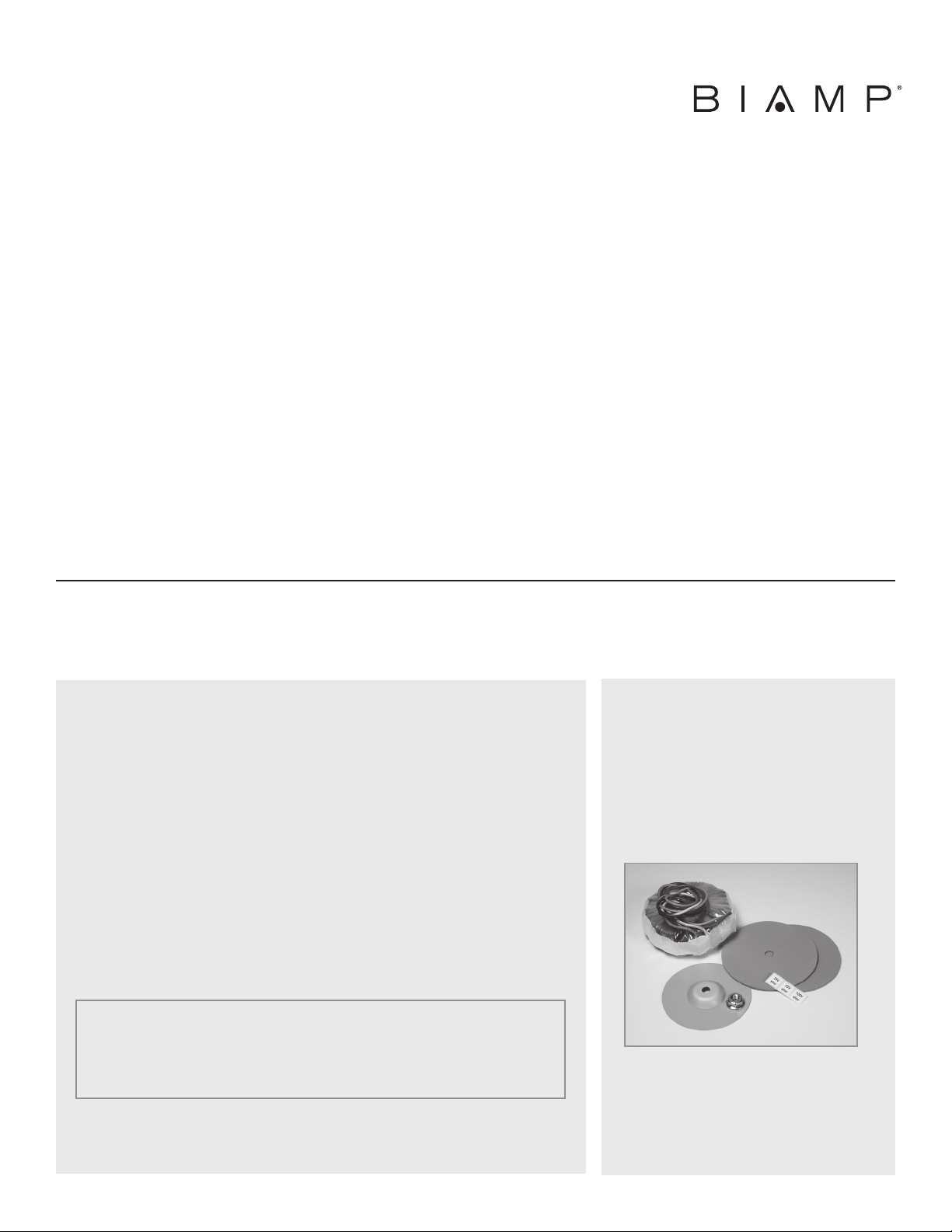
KIT CONTENTS:
• (1) Transformer
• (1) Holding nut
• (2) rubber washers
• (1) Metal dome washer
• (1) stickers
• (1) Instructions
RECOMMENDED TOOLS:
• Phillips screwdriver
• Adjustable wrench
• Pliers
Page 2
TDT50 & TDT150 INSTALLATION INSTRUCTIONS
1. Disconnect AC power from the amplier.
2. Remove the amplier top panel by removing 17 screws
(6 on each side, 3 on back and 2 on front).
Please note that front screws are longer.
3. If the mounting bolts have two nuts, remove one and
save. These nuts will be used to hold the transformers
in place. If the mounting bolts have only one nut, do
not remove. Transformer will be held in place with
supplied nut.
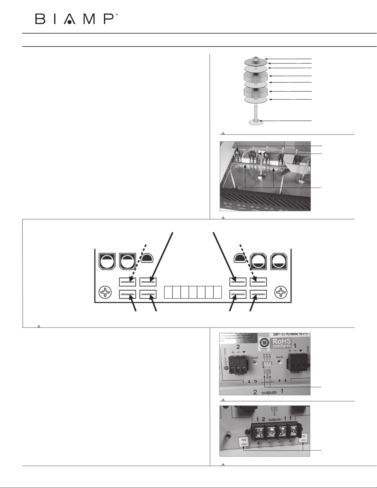
4. Install transformers as shown in gure 1.
5. Locate the amplier circuit boards and jumpers.
Each amplier card represents two individual output
channels; one odd and one even (refer to gure 2 for
reference).
6. Using a pair of pliers, remove the black and red jumper
from the associated amplier channel.
7. Following the diagram below (gure 3), connect the
wires as indicated.
Please note that wires on odd channel are
mirrored from wires on even channel.
Brown wire = 25V
Orange wire = 70V
Yellow wire = 100V
Blue wire Blue wire
Nut
Metal Dome Washer
Rubber Washer
Transformer
Rubber Washer
Transformer
Rubber Washer
Bolt
FIGURE 1
Odd channel
jumpers (Ch 1)
Even channel
jumpers (Ch2)
Amplier
Cards
FIGURE 2
Brown wire = 25V
Orange wire = 70V
Yellow wire = 100V
Odd
Channels
(1, 3, 5, & 7)
Green wire Green wireBlack wire Black wire
FIGURE 3
8. Replace amplier top panel (longer screws go on the
front).
9. Assign channel HPF (High Pass Filter) by ipping the
appropriate channel rear panel dip switch. (gure 4)
10. Apply appropriate rear panel “xfmr” voltage sticker.
(gure 5)
Even
Channels
(2, 4, 6, & 8)
High Pass Filter
(HPF)
dip switches
FIGURE 4
FIGURE 5
Afx transformer
stickers
Page 3

TDT100 & TDT300 INSTALLATION INSTRUCTIONS
1. Disconnect AC power from the amplier.
2. Remove the amplier top panel by removing 17 screws
(6 on each side, 3 on back and 2 on front).
Please note that front screws are longer.
3. If the mounting bolts have two nuts, remove one and
save. These nuts will be used to hold the transformers
in place. If the mounting bolts have only one nut, do
not remove. Transformer will be held in place with
supplied nut.
4. Install transformers as shown in gure 6.
FIGURE 6
5. Locate the amplier circuit boards and jumpers.
Each amplier card represents two individual output
channels; one odd and one even (refer to gure 7 for
reference).
6. Using a pair of pliers, remove the red jumper from
both amplier channels.
7. Following the diagram below (gure 8), connect the
wires as indicated.
FIGURE 7
Nut
Metal Dome Washer
Rubber Washer
Transformer
Rubber Washer
Bolt
Odd channel
jumpers (Ch 1)
Even channel
jumpers (Ch2)
Amplier
Cards
Orange wire = 70V
Blue wire Green wire
Yellow wire = 100V
Odd
Channels
(1, 3, 5, & 7)
FIGURE 8
8. Replace amplier top panel (longer screws go on the
front).
9. Assign channel HPF (High Pass Filter) by ipping the
appropriate channel rear panel dip switch. (gure 9)
10. Assign bridge mode by ipping the rear panel bridge dip
switch (gure 9)
11. Apply appropriate rear panel “xfmr” voltage sticker.
(gure 10)
Black wireBrown wire = 25V
Even
Channels
(2, 4, 6, & 8)
Bridge
dip switch
High Pass Filter
(HPF)
dip switches
FIGURE 9
FIGURE 10
Afx transformer
stickers
Page 4

DoC MCA201003
EC Declaration of Conformity
Biamp Systems Corporation, as manufacturer having sole responsibility, hereby
declares that the following described product complies with the applicable provisions of
the DIRECTIVES below except as noted herein. Any alterations to the product not
agreed upon and directed by Biamp Systems Corporation will invalidate this declaration.
Product Models: MCA 8050 with optional Output Transformers TDT50 or TDT100
MCA 8150 with optional Output Transformers TDT150 or TDT300
Product Description
Applicable EC Directives
LVD Directive (2006/95/EC) Safety EN 60065:2002
EMC Directive (2004/108/EC) Emissions EN 55103-1:1996, Environment E2
Immunity EN 55103-2:1996
Special Considerations for Product Environment or Compliance:
Shielded cabling must be used for system connections.
Technical Documentation File, Location and Contact:
Biamp Systems, Inc. phone: (503) 641.7287
9300 S.W. Gemini Drive fax: (503) 626.0281
Beaverton, OR USA 97008 e-mail: biamp@biamp.com
: Audio Amplifiers and Distribution Transformers
: Applicable Harmonized Standards:
Authorized Representative: Larry Copley, Compliance Engineer
Authorized Signature:
Issued: March, 2010
Page 5

Biamp Systems | 9300 S.W. Gemini Drive | Beaverton, OR | 97008 | USA | +1.503.641.7287 | www.biamp.com
 Loading...