

Page 1

Vocia
®
POTS-1-2
&
POTS-1-4
Operation Manual
April 2014
Biamp Systems, 9300 SW Gemini Drive, Beaverton, Oregon 97008 U.S.A. (503) 641-7287 www.biamp.com
Page 2

TABLE OF CONTENTS
VOCIA TELEPHONE PAGING ADAPTER (POTS-1). ................................4
FEATURES ..............................................................................4
SETUP AND USE ............................................................5
FRONT PANEL INFORMATION ..............................................................5
Power (Chassis Indicator) .................................................................5
Fault (Chassis Indicator) ..................................................................5
Activity (Chassis Indicator) ................................................................6
Status (Chassis Indicator) .................................................................6
Line Status ............................................................................6
Hook Status ...........................................................................6
REAR PANEL INFORMATION ...............................................................7
Power ................................................................................7
Device ID .............................................................................7
Network ...............................................................................8
POTS Connections ......................................................................8
VOCIA POTS-1 SPECIFICATIONS ..............................................9
WARRANTY ...............................................................10
COMPLIANCE .............................................................11
EC DECLARATION OF CONFORMITY ..........................................13
ROHS COMPLIANCE AND HAZARDOUS SUBSTANCE TABLE .....................14
2
Page 3
IMPORTANT SAFETY INSTRUCTIONS
1) Read these instructions.
2) Keep these instructions.
3) Heed all warnings.
4) Follow all instructions.
5) Do not use this product near water.
6) Clean only with dry cloth.
7) Do not block ventilation openings. Install in
accordance with the manufacturer’s instructions.
8) Do not install near any heat sources such as
radiators, heat registers, stoves, or other products
(including ampliers) that produce heat.
9) Do not defeat the safety purpose of the groundingtype plug. A grounding type plug has two blades and a
third grounding prong.
The third prong is provided for your safety. If the
provided plug does not t into your outlet, consult an
electrician for replacement of the obsolete outlet.
10) Protect the power cord from being walked on or
pinched, particularly at plugs, convenience receptacles
and the point where they exit from the product.
Explanation of Graphical Symbols:
Lightning Bolt: Hazardous Live voltages present when this unit is in operation. Do not touch terminals marked with
this symbol while the unit is connected to live power.
Exclamation Point: Replace components (i.e. fuses) only with the values specied by the manufacturer. Failure to
do so will compromise safe operation of this unit
11) Only use attachments/accessories specied by the
manufacturer.
12) Use only with equipment rack,
cart, stand or table designed to provide
adequate mechanical strength, heat
dissipation and securement to the
building structure.
When a cart is used, use caution when moving the cart
and product combination to avoid injury from tip-over.
13) Unplug this product during lightning storms or when
unused for long periods of time.
14) Refer all servicing to qualied service personnel.
Servicing is required when the product has been
damaged in any way, such as power-supply cord or
plug is damaged, liquid has been spilled or objects have
fallen into the product, the product has been exposed to
rain or moisture, does not operate normally, or has been
dropped.
Hazardous Moving Fan Blades: Remove power before servicing and keep away from moving fan blades.
WARNING - To reduce the risk of re or electric shock, do not expose these products to rain or moisture. These products must
not be exposed to dripping or splashing and no objects lled with liquids, such as vases, shall be placed on these products.
WARNING – 100 Volt Speaker terminals marked with the symbol are Hazardous Live. External wiring connected to these
terminals requires installation by a Skilled or Instructed Person.
WARNING – MAINS Powered Products employ Safety Grounding and must be connected to a MAINS socket that is properly
grounded to provide a protective earthing connection.
Disconnect Device - The MAINS plug is used to disconnect MAINS power and must remain readily operable.
CAUTION – When POTS Telephone Interface options are provided, connections to the telecom circuits of this device must
be made by qualied, trained personnel. To reduce the risk of re, use only No. 26 AWG solid copper wire for telecom circuit
connections.
Intended for Installation and Service by Skilled Personnel Only:
CAUTION – To reduce the Risk of Electric Shock, Installation and Service of Biamp Products should be conducted only by
Skilled Persons who are Biamp Qualied Audio Installation Professionals.
Do not perform any servicing other than that contained in the Operating Instructions unless you are a Skilled Person qualied
to do so.
Skilled Persons must disconnect AC MAINS Power before opening product.
CAUTION - The Installation steps for ‘Auxiliary Power’ are for use by Skilled Personnel only and must comply with all local
codes.
• National Electrical Code, ANSI/NFPA 70 for United States.
• Canadian Electrical Code, Part 1, CSA C22.1, Sections 2-128, 12-010(3) and 12-100 for Canada.
Wall Mounting Instructions – Wall mounted products must be securely fastened to drywall or similar surface using a
minimum of 4 wood screws (2 screws for product with only two mounting holes). Alternate fasteners which may be used
include drywall anchors, self-tapping sheet metal screws located in metal studs or wood screws extending a minimum of ½
inch into wood studs.
3
Page 4

VOCIA TELEPHONE PAGING ADAPTER (POTS-1)
The Vocia Telephone Paging Adapter 1 (POTS-1) facilitates a direct connection from two (POTS-1-2) or four (POTS-1-4) Plain Old Telephone
Service (POTS) lines, or POTS-based PBX telephone systems. The interface permits live, real-time paging using any Page Code within
the Vocia system. When calling into a POTS line, a number of software-congurable voice prompt functions are available including Page
Code selection, Zone status indication and Page Now indication. A DTMF sequence of tones can also be programmed in the software to be
associated with a Vocia Control Input Event.
In the event of a busy Zone status, the POTS-1 supports Page Stacking and Store-and-Forward message queuing.
The POTS-1 supports Pre-recorded Messages when a Message Server-1 (MS-1) is present in the system. The POTS-1 also supports
Emergency Paging functions when a Vocia Life Safety Interface (LSI-16 or LSI-16e) is present in the system.
Features
• Two or four POTS lines (model dependent)
• Device monitoring
• Power via 24V DC supply (dual redundant inputs)
• Software-congurable signal processing
• Rack mountable (1RU)
• CobraNet® audio and control over a single Ethernet cable
• Dual CobraNet Ports for redundancy
• Rotary switches for device identication
• IP30 Compliant
• CE marked, UL listed and RoHS compliant
• Covered by Biamp Systems 5-year warranty
4
Page 5

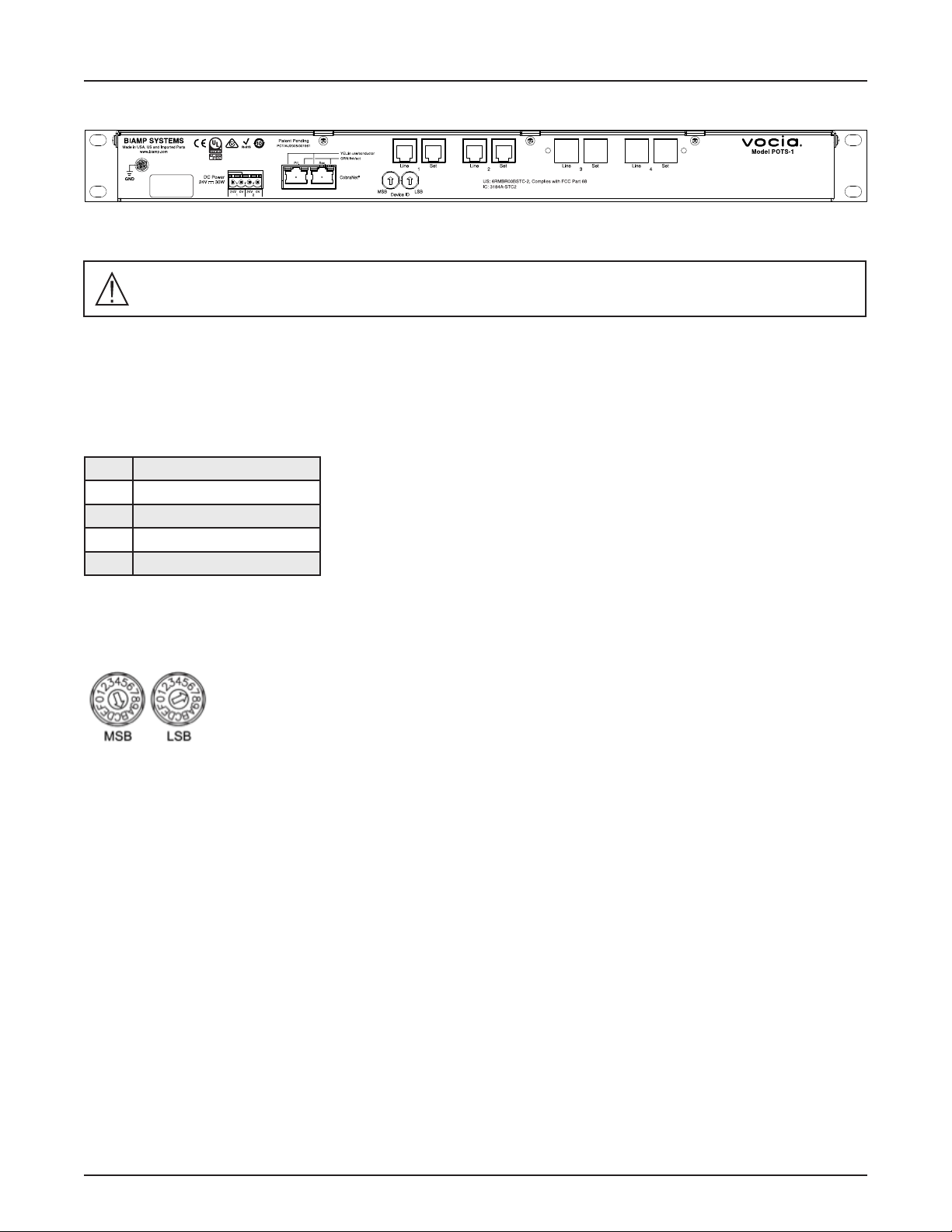
VOCIA TELEPHONE PAGING ADAPTER (POTS-1) FRONT PANEL
Setup and Use
The Vocia software provides the interface for conguring and programming the POTS-1. The information supplied by this manual relates to
hardware installation, physical connections, and device information. For more details on software setup, please consult the Vocia Software
Help File.
Front Panel Information
The POTS-1 LEDs are as follows (from left to right when viewing the front of the chassis):
1. 24V DC power 1
2. 24V DC power 2
3. Fault
4. Activity
5. Status
6. Line 1 Line Status
7. Line 1 Hook Status
8. Line 2 Line Status
9. Line 2 Hook Status
10. Line 3 Line Status ( functional for POTS-1-4 model only)
11. Line 3 Hook Status (functional for POTS-1-4 model only)
12. Line 4 Line Status (functional for POTS-1-4 model only)
13. Line 4 Hook Status (functional for POTS-1-4 model only)
Power (Chassis Indicator)
The POTS-1 has two power indicators. If power is applied to one or both 24V DC power connectors, the corresponding LED will be on.
• Off – The corresponding power connection is not in the working voltage range.
• Solid green – The corresponding power connection is receiving 24V DC power.
Fault (Chassis Indicator)
There are two types of chassis Faults that will be reported, depending on the severity of the problem. Audio may still be passing, but if the
condition causing the warning is not corrected, a failure may occur.
• Off – Normal operation.
• Flashing – A warning has occurred, meaning some aspect of the unit chassis is not performing within normal specications.
• Solid – A fault has occurred, meaning some aspect of the unit has failed and audio may not be passing.
5
Page 6

VOCIA TELEPHONE PAGING ADAPTER (POTS-1) FRONT PANEL
Activity (Chassis Indicator)
The POTS-1 has an activity LED that will illuminate to show the conguration status of the unit.
• Off – The unit is not congured.
• Solid green – The unit is congured.
Status (Chassis Indicator)
The POTS-1 has a tri-color Status LED that indicates the health of the hardware.
• Solid green – The unit is powered-up and working normally.
• Flashing amber – Will be shown briey during the power-up self test and will turn steady green upon a successful start.
• Solid red – The unit experienced a problem during the power-on self test.
Line Status
• Solid green – Indicates no line fault – loop current and voltage is normal.
• Solid amber – Indicates over-voltage and/or under-current line faults.
Hook Status
• Off – Line is not in use (on hook).
• Solid green – Line is in use (off hook).
Note: The third and fourth ‘Line’ and ‘Hook’ status LEDs will remain extinguished at all times on the POTS-1-2 model.
6
Page 7
VOCIA TELEPHONE PAGING ADAPTER (POTS-1) REAR PANEL
Rear Panel Information
Power
Caution – Due to potential energy hazard, connections to the Aux Power 24V DC inputs must be
made by qualied electrician or other qualied person as required to conform with all local codes.
The POTS-1 requires a 24V DC power source to operate, but is capable of accepting dual 24V DC inputs for redundancy. Both power
sources may be connected concurrently, however each must be capable of supporting the full 30-Watt load of the unit (inputs are not
intended to load-share). Loss or return of either power source will not result in an interruption to normal operation as long as one of these
power sources remains functional. Monitoring of all power sources is selectable via the Vocia software.
The power connector is a four-way 5.08mm standard header with mating pluggable screw terminal block with cable restraint.
Pin Function
1 DC Power 1 24V(+)
2 DC Power 1 24V(-)
3 DC Power 2 24V(+)
4 DC Power 2 24V(-)
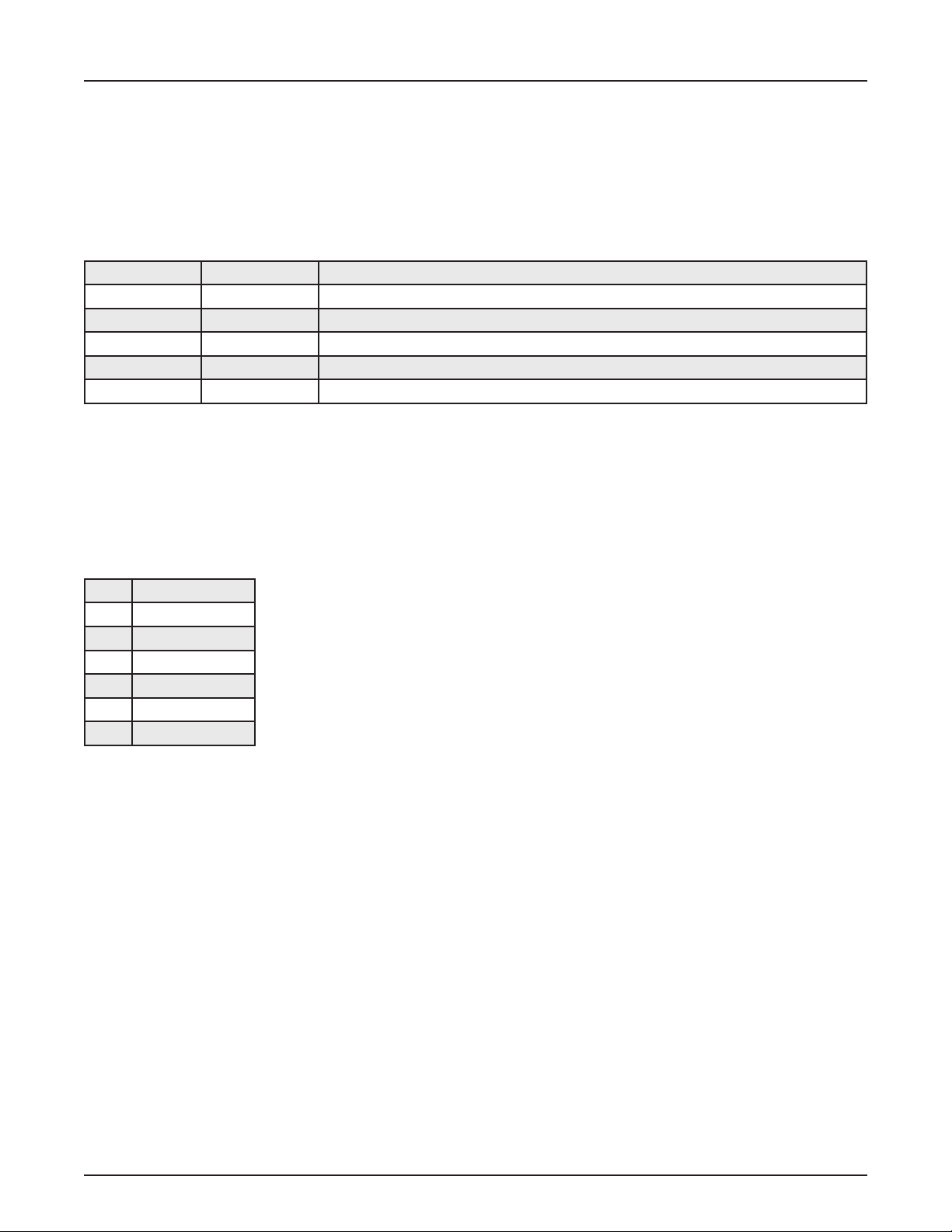
Device ID
The rotary ID switches on the POTS-1 give the unit a unique Device ID. The switches are in hexadecimal format. All POTS-1 units must
have a unique Device ID to function within a Vocia Paging World (i.e. it is not possible to have two POTS-1 units with the same Device
ID of hex 07). To assign a Device ID of hex 07, turn the MSB switch on 0 and leave the LSB switch to 7. To create
an ID of hex B7, turn the MSB switch to B and turn the LSB switch to 7. Device ID switches should be set using a
0.1 inch (2.5mm) to 0.12 inch (3.0mm) at blade screwdriver. More information on setting IDs and the hexadecimal
numbering scheme used in Vocia can be found in the Vocia Help File. Please note: changes made to the Device ID
while connected to the network require a power cycle in order to take effect.
7
Page 8
VOCIA TELEPHONE PAGING ADAPTER (POTS-1) REAR PANEL
Network
The POTS-1 is designed to be used in a single Vocia World and utilizes the Vocia CobraNet LAN to communicate with the rest of the Vocia system.
The unit has two monitored RJ-45 Ethernet network connectors that allow a redundant connection to be utilized if required. The primary
connection will always have priority over the secondary connection. Monitoring of the secondary connection can be disabled in Vocia software.
The RJ-45 connectors use two LEDs to indicate Ethernet link and network activity (see table below).
Left LED Right LED Description
None None No Data Connectivity or CobraNet activity
None Flashing green Link established
Solid amber Flashing green Link established and CobraNet activity detected. The unit is acting as a CobraNet Performer.
Flashing amber Flashing green Link established and CobraNet activity detected. The unit is acting as a CobraNet Conductor.
Flashing amber None CobraNet fault. Check cabling and conguration for errors.
The maximum distance between any unit and an Ethernet switch is 328 feet (100 meters) when using copper cabling. Additional Ethernet
switches and/or ber-optic cable can be used to further extend distances between units on a network. Please note that CobraNet limits
network extensions to seven hops (one-way transmissions) within a network.
POTS Connections
A Line and Set RJ-11 connection is provided per telephone line. These are wired in parallel and allow a local handset to be used on the Set line.
The pin listing below applies to both the Line and Set connectors.
Pin Function
1 NC
2 Loop
3 Ring
4 Tip
5 Loop
6 NC
8
Page 9

VOCIA TELEPHONE PAGING ADAPTER (POTS-1) SPECIFICATIONS
Vocia POTS-1 SPECIFICATIONS
Network Audio 20-bits, 48kHz, 5-1/3ms (fixed)
Network Connection: Dual RJ45 with shielded Ethernet cable
(CAT5, CAT5e, CAT6, or CAT7)
Overall Dimensions:
Height: 1.75 Inches (44.4mm)
Width: 19 Inches (482.5mm)
Depth: 9 Inches (228.6mm)
Weight: 2.4lbs (1.1kg)
POTS Interface:
Ringer Equivalency Number (REN): 0.0
Dynamic Range: 67dB
Frequency Response: 250Hz – 3.4kHz
THD: < 0.3%
Transhybrid balance: 30dB
Power:
DC Power: 24V DC; <100mV Ripple (Max 30W)
Environment:
Ambient Operating Temperature Range:: 18-108 degrees F
(-8 – 42° C)
Altitude: 0–10,000 Feet (0-3000 meters) MSL
Humidity: 0 – 100% non-condensing
Compliance: FCC Part 15B (USA)
FCC Part 68 (USA)
Industry Canada CS-03 (Canada)
CE marked (Europe)
UL and C-UL listed (USA & Canada)
RCM (Australia)
EAC (Eurasian Customs Union)
RoHS Directive (Europe)
9
Page 10

WARRANTY
BIAMP SYSTEMS IS PLEASED TO EXTEND THE FOLLOWING 5-YEAR LIMITED WARRANTY TO THE ORIGINAL PURCHASER OF
THE PROFESSIONAL SOUND EQUIPMENT DESCRIBED IN THIS MANUAL
1. Biamp Systems warrants to the original purchaser of new products that the product will be free from defects in material and workmanship for a period of 5 YEARS from the date of purchase from an authorized Biamp Systems dealer, subject to the terms and conditions
set forth below.
2. If you notify Biamp Systems during the warranty period that a Biamp Systems product fails to comply with the warranty, Biamp
Systems will repair or replace, at Biamp Systems’ option, the nonconforming product. As a condition to receiving the benets of this
warranty, you must provide Biamp Systems with documentation that establishes that you were the original purchaser of the products.
Such evidence may consist of your sales receipt from an authorized Biamp Systems dealer. Transportation and insurance charges to
and from the Biamp Systems factory for warranty service shall be your responsibility.
3. This warranty will be VOID if the serial number has been removed or defaced; or if the product has been altered, subjected to damage,
abuse or rental usage, repaired by any person not authorized by Biamp Systems to make repairs; or installed in any manner that does
not comply with Biamp Systems’ recommendations.
4. Electro-mechanical fans, electrolytic capacitors, gooseneck microphones, cords connecting handheld microphones, hard-drives,
displays, and normal wear and tear of items such as paint, knobs, handles, keypads and covers are not covered under this warranty.
All server-based devices are warranted for 3 years only.
5. This warranty is in lieu of all other warranties, expressed or implied. Biamp Systems disclaims all other warranties, expressed or
implied, including, but not limited to, implied warranties of merchantability and tness for a particular purpose.
6. The remedies set forth herein shall be the purchaser’s sole and exclusive remedies with respect to any defective product.
7. No agent, employee, distributor or dealer of Biamp Systems is authorized to modify this warranty or to make additional warranties on
behalf of Biamp Systems. Statements, representations or warranties made by any dealer do not constitute warranties by Biamp Systems.
Biamp Systems shall not be responsible or liable for any statement, representation or warranty made by any dealer or other person.
8. No action for breach of this warranty may be commenced more than one year after the expiration of this warranty.
9. Biamp Systems shall not be liable for special, indirect, incidental, or consequential damages, including lost prots or loss of use arising
out of the purchase, sale, or use of the products, even if Biamp Systems was advised of the possibility of such damages.
101010
585.0385.90A
Page 11

COMPLIANCE
FCC COMPLIANCE
FCC Notice - Class A digital device - This equipment has been tested and found to comply with the limits for a Class A digital device,
pursuant to Part 15 of the FCC Rules. These limits are designed to provide reasonable protection against harmful interference when the
equipment is operated in a commercial environment. This equipment generates, uses, and can radiate radio frequency energy and, if not
installed and used in accordance with the instruction manual, may cause harmful interference to radio communications. Operation of this
equipment in a residential area is likely to cause harmful interference in which case the user will be required to correct the interference at
own expense.
TELECOM COMPLIANCE
CAUTION – For protection against overvoltage on telecommunication circuits, for example from power line crosses; use minimum No. 26
AWG telecommunication line cord.
Telephone Interface Information - This equipment complies with Part 68 of the FCC rules and the requirements adopted by the ACTA.
On the rear panel of this equipment are markings that contain, among other information, telecom product identier US:6RMBR00BSTC-2.
If requested, this number must be provided to the telephone company.
This equipment is designed for modular connection with Universal Service Order Codes (USOC) RJ-11C, RJ-11W, RJ-14C, RJ-14W.
A plug and jack used to connect this equipment to the premises wiring and telephone network must comply with the applicable FCC Part
68 rules and requirements adopted by the ACTA. A compliant telephone cord and modular plug is provided with this product. It is designed
to be connected to a compatible modular jack that is also compliant. See installation instructions for details.
Ringer Equivalency Number (REN) - The REN is used to determine the number of devices that may be connected to a telephone line.
Excessive RENs on a telephone line may result in the devices not ringing in response to an incoming call. In most but not all areas, the
sum of RENs should not exceed ve (5.0). To be certain of the number of devices that may be connected to a line, as determined by the
total RENs, contact the local telephone company. The REN for this product is 0.0 as indicated by part of the product identier that has the
format US:AAAEQ##TXXXX. The digits represented by ## are the REN without a decimal point (e.g., 00 is a REN of 0.0).
Alarms connected to telephone line - If your facility has specially wired alarm equipment connected to the telephone line, ensure the
installation of this US:6RMBR00BSTC-2 does not disable your alarm equipment. If you have questions about what will disable alarm
equipment, consult your telephone company or a qualied installer.
Automatic Dialer - WHEN PROGRAMMING EMERGENCY NUMBERS AND (OR) MAKING TEST CALLS TO EMERGENCY NUMBERS:
1. Remain on the line and briey explain to the dispatcher the reason for the call.
2. Perform such activities in the off-peak hours, such as early morning or late evenings.
Electrical Safety Advisory - Telephone companies report that electrical surges, typically lightning transients, are very destructive
to customer terminal equipment connected to AC power sources. The use of a surge arrestor on the telephone line is recommended,
particularly in areas that are prone to lightning strikes.
Service - This equipment is not user serviceable. If trouble is experienced with this equipment US:6RMBR00BSTC-2, for repair or warranty
information, please contact Biamp Systems Corporation, phone number 503.641.7287. If the equipment is causing harm to the telephone
network, the telephone company may request that you disconnect the equipment until the problem is resolved.
If this equipment US:6RMBR00BSTC-2 causes harm to the telephone network, the telephone company will notify you in advance that
temporary discontinuance of service may be required. But if advance notice isn’t practical, the telephone company will notify the customer
as soon as possible. Also, you will be advised of your right to le a complaint with the FCC if you believe it is necessary.
111111
Page 12

COMPLIANCE
The telephone company may make changes in its facilities, equipment, operations or procedures that could affect the operation of the
equipment. If this happens, the telephone company will provide advance notice in order for you to make necessary modications to
maintain uninterrupted service.
Party Lines - Connection to party line service is subject to state tariffs. Contact the state public utility commission, public service
commission or corporation commission for information.
New Zealand Telecom Notice
New Zealand Telepermit - The grant of a Telepermit for any item of terminal equipment indicates only that Telecom has accepted that the item
complies with minimum conditions for connection to its network. It indicates no endorsement of the product by Telecom, nor does it provide
any sort of warranty. Above all, it provides no assurance that any item will work correctly in all respects with another item of Telepermitted
equipment of a different make or model, nor does it imply that any product is compatible with all of Telecom’s network services
This equipment shall not be set up to make automatic calls to the Telecom ‘111’ Emergency Service
IMPORTANT NOTICE - Under power failure conditions, this telephone may not operate. Please ensure that a separate telephone, not
dependent on local power, is available for emergency use.
121212
Page 13

COMPLIANCE
DoC VPOTS201311
EC Declaration of Conformity
Biamp Systems Corporation, as manufacturer having sole responsibility, hereby declares
that our delivered version the following described product complies with the applicable
provisions of the DIRECTIVES below except as noted herein. Any alterations to the product
not agreed upon and directed by Biamp Systems Corporation will invalidate this declaration.
Brand Name: Vocia
Product Description: POTS Telephone Interface Expander
Model: Vocia POTS-1
®
Applicable EC Directives: Applicable Harmonized Standards:
LVD Directive (2006/95/EC) Safety EN 60065:2002, + A1:2006,
+ A11:2008, + A2:2010, + A12:2011
EMC Directive (2004/108/EC) Emissions EN 55103-1:2009, Environment E2
Immunity EN 55103-2:2009, Environment E2
R&TTE Directive (1999/5/EC) Terminal Equipment
RoHS Directive (2011/65/EU) RoHS Recast
Special Considerations for Product Environment or Compliance:
Use only CE marked Power over Ethernet (PoE) power supply and/or DC power supply.
Shielded cabling must be used for system connections.
Technical Construction File, Location and Contact:
Biamp Systems Corporation phone: +503.641.7287
9300 S.W. Gemini Drive fax: +503.626.0281
Beaverton, OR USA 97008 e-mail: compliance@biamp.com
Authorized Representative: Larry Copley, Compliance Engineer
Authorized Signature:
Date and Place Issued: November 2013, Beaverton, Oregon USA
1313
Page 14

COMPLIANCE
EU RoHS COMPLIANT
This Biamp product, including all attendant cables and accessories supplied by
Biamp, meets all requirements of EU Directives 2011/65/EU.
The information below is presented in accordance with similar requirements of
Chinese law SJ/T11363-2006.
有害物质表 (Hazardous Substances Table)
Biamp Systems Corporation
音频输入设备 (Audio Input Device)
型号 POTS-1-2, POTS-1-4
有毒有害物质或元素 (Substances)
Pb
部件名称 (Part Name)
设备机箱 (Equipment Chassis) X O X O O O
插拔式接线端子 (Plug-in Terminal Blocks) O O O O O O
铅
Hg
汞
Cd
镉
Cr+6
六价铬
PBB PBDE
交直流电源适配器 (AC-DC Power Supply Adaptor) X O X O O O
电源线 (Power Cord) O O O O O O
手册和其他书面文档 (Manual and Paper Documents) O O O O O O
包装箱和所有包装材料 (Box and Packing Materials) O O O O O O
0:表示该部件所有均质材料中的这种有毒有害物质低于 SJ/T11363-2006 的限制要求.
X:表示该部件中至少有一种均质材料所含的这种有毒有害物质高于 SJ/T11363-2006 的限制要求.
在电触头和(或)镀镉所含的均质材料中,镉及其化合物的含量可以超过 0.01%,但欧盟指令 91/338/EEC(根据欧
盟指令 76/769/EEC)限制销售和使用某些危险物质和制剂部分中所禁止的用途除外
在以下一种或多种物质所含的均质材料中,铅及其化合物的含量可以超过 0.1%:
1. 电子元器件中玻璃内所含的铅
2. 铅在钢材中是作为一种合金元素,含量可达 0.35%
3. 铅在铝材中是作为一种合金元素,含量可达 0.4%
4. 铅在铜材中是作为一种合金元素,含量可达 4%
5. 高熔点类焊料中的铅(即铅料合金,铅含量超过 85%)
6. 电子陶瓷部件内的铅
7. 由两种以上元素组成的焊料中所含的铅,用于连接针脚和微处理器包装,其中铅
的含量超过 80% 但低于 85%
8. 顺应针连接系统内的铅
9. 倒装芯片封装中半导体芯片及载体之间形成可靠连接所用焊料中的
在正常使用情况下,中国环保使用期限为 10 年,条件是:
• 环境温度为 (Ambient Temperature) 0-40C (32-104°F)
• 湿度为 0-95%,无凝结
• 海拔高度为 0-10,000 英尺
• 气流不受阻碍
• 没有水或其他液体进入任何部件
• 电源为 (Power Supply) 100-240 Vac, 50/60 Hz, 1.7A
• 部件没有损坏(损坏部件应立即修理)
• 由工厂授权人员使用批准的材料进行所有维修
1414
Page 15

INSTRUCCIONES DE SEGURIDAD IMPORTANTES
1) Lea estas instrucciones.
2) Guarde estas instrucciones.
3) Preste atención a todas las advertencias.
4) Siga todas las instrucciones.
5) No utilice este producto cerca del agua.
6) Limpie solo con un paño seco.
7) No obstruya los oricios de ventilación. Instale el
producto según las instrucciones del fabricante.
8) No lo instale cerca de ninguna fuente de calor como
radiadores, rejillas de calefacción, estufas u otros
productos (incluidos amplicadores) que produzcan
calor.
9) No anule el propósito de seguridad del enchufe con
conexión a tierra. Un enchufe con conexión a tierra
tiene dos clavijas y una tercera punta con conexión a
tierra.
La tercera punta se provee para su seguridad. Si el
enchufe suministrado no se adapta a su tomacorriente,
recurra a un electricista para reemplazar la toma
obsoleta.
10) Proteja el cable de alimentación eléctrica para
evitar que sea pisado o aplastado, en especial en los
enchufes, receptáculos convenientes y el punto donde
salen del producto.
11) Solo utilice complementos/accesorios indicados por
el fabricante.
12) Utilice solo con el soporte,
carro, base o mesa diseñados para
proporcionar fuerza mecánica adecuada,
disipación del calor y seguridad a la
estructura del edicio.
Cuando se utiliza un carro, tenga cuidado al mover
la combinación del carro con el producto para evitar
lesiones en caso de una caída.
13) Desenchufe este producto durante tormentas
eléctricas o si no va a utilizarlo por largos períodos de
tiempo.
14) Todas las reparaciones deben ser realizadas por
personal calicado. La reparación es necesaria cuando
el producto presenta cualquier tipo de daño como,
por ejemplo, si se deteriora el cable de alimentación
eléctrica o enchufe, si se derraman líquidos o caen
objetos dentro del producto, si se expone el producto a
la lluvia o humedad, si no funciona normalmente o si se
ha caído.
Explicación de los símbolos grácos:
Rayo: Voltajes activos peligrosos mientras la unidad está en funcionamiento. No toque las terminales marcadas
con este símbolo mientras la unidad se encuentre conectada a una salida activa de energía.
Signo de exclamación: Reemplace los componentes (es decir, los fusibles) solo de acuerdo con los valores
indicados por el fabricante. De no hacerlo, se pondrá en riesgo el funcionamiento seguro de esta unidad.
Aspas de ventilador en movimiento peligrosas Desenchufe el producto antes de realizar reparaciones y aléjelo de
las aspas en movimiento de los ventiladores.
1515
Page 16

INSTRUCCIONES DE SEGURIDAD IMPORTANTES
ADVERTENCIA – Para reducir el riesgo de incendio o descarga eléctrica, no exponga estos productos a la lluvia o humedad.
Estos productos no deben exponerse a goteos o salpicaduras ni deben posarse sobre ellos objetos que contengan líquidos
como, por ejemplo, jarrones.
ADVERTENCIA – Las terminales de altavoces de 100 voltios que aparecen marcadas con el símbolo están activas y
son peligrosas. La conexión externa de cables a estas terminales requiere la instalación a cargo de una persona calicada o
debidamente instruida.
ADVERTENCIA – Los productos con alimentación eléctrica utilizan conexión a tierra de seguridad y deben conectarse a
tomacorrientes que funcionen correctamente para brindar una conexión a tierra de protección.
Desconexión del dispositivo – El enchufe de alimentación eléctrica se utiliza para desconectar esta alimentación y deberá
poder accionarse fácilmente.
PRECAUCIÓN – Cuando se proporcionan las opciones de interfaz telefónica POTS, las conexiones a los circuitos de
telecomunicaciones de este dispositivo deber ser realizadas por personal calicado y entrenado. Para reducir el riesgo de
incendio, use solo cables de cobre sólido N.° 26 AWG para las conexiones de los circuitos de telecomunicaciones.
Para la instalación y mantenimiento solo por parte de personal calicado:
PRECAUCIÓN – Para reducir el riesgo de descarga eléctrica, la instalación y el mantenimiento de los productos Biamp deben
ser realizados por personas calicados que formen parte de los Profesionales capacitados en la instalación de audio de
Biamp.
No realice ninguna reparación que no se encuentre en las Instrucciones de uso, a menos que sea una persona calicada para
hacerlo.
Las personas calicadas deben desenchufar la alimentación eléctrica de CA antes de abrir el producto.
PRECAUCIÓN – Los pasos para la instalación de una “energía auxiliar” están dirigidos solo al personal calicado y deben
cumplir con todos los códigos locales.
• Código eléctrico nacional: ANSI/NFPA 70 para los Estados Unidos.
• Código eléctrico canadiense: parte 1, CSA C22.1, secciones 2-128, 12-010(3) y 12-100 para Canadá.
Instrucciones para el montaje sobre la pared – Los productos que sean montados sobre la pared deben estar bien
ajustados al yeso u otra supercie con el uso de, al menos, 4 tornillos para madera (2 tornillos para los productos con solo
dos oricios de montaje). Los enganches alternativos que pueden utilizarse incluyen pernos de anclaje para paredes de yeso,
tornillos de metal laminado con rosca cortante los cuales se ubican en montantes de metal o tornillos para madera que se
prolongan poco más de 1,5 cm dentro de los montantes de madera.
1616
Page 17

CONSIGNES DE SÉCURITÉ IMPORTANTES
1) Lisez attentivement les présentes instructions.
2) Conservez les présentes instructions.
3) Prêtez une extrême attention aux avertissements.
4) Respectez toutes les consignes données.
5) N’utilisez pas ce produit à proximité d’eau.
6) Nettoyez uniquement avec un chiffon sec.
7) Ne bouchez pas les ouvertures destinées à la
ventilation. Suivez les instructions d’installation du
fabricant.
8) Tenez le produit à l’écart des sources de chaleur,
comme les radiateurs, les grilles d’air chaud, les
cuisinières ou autres produits (dont amplicateurs) qui
émettent de la chaleur.
9) Préservez la protection offerte par le branchement de
mise à la terre. Le connecteur est reconnaissable par
ses deux broches accompagnées d’un contact de mise
à la terre.
Ce troisième contact est fourni pour votre sécurité. Si
le connecteur fourni ne correspond pas à votre prise,
renseignez-vous auprès d’un électricien.
10) Placez le cordon à l’écart des zones de passage
et veillez à ce qu’il ne soit pas pincé, en particulier au
niveau des prises, des multiprises et de la sortie de
l’appareil.
11) Utilisez exclusivement les xations/accessoires
spéciés par le fabricant.
12) Utilisez uniquement des tables,
supports, étagères ou chariots capables
de supporter le poids du produit et
d’offrir la dissipation de chaleur et la
sécurité requises (xation à la structure
du bâtiment).
Si vous placez le produit sur un chariot, déplacez-le avec
précaution pour éviter de le renverser.
13) Débranchez le produit pendant les orages ou les
périodes d’inutilisation prolongées.
14) Conez toutes les interventions à un personnel
qualié. Ces interventions peuvent s’avérer nécessaire
dans certaines situations : détérioration du produit
(connecteur ou cordon d’alimentation endommagé, par
exemple), liquide renversé sur le produit, objets tombés
dans le produit, exposition du produit à l’humidité ou à
la pluie, fonctionnement anormal du produit, chute du
produit, etc.
Signication des pictogrammes:
Éclair : tensions dangereuses présentes lorsque l’appareil est en fonctionnement. Ne touchez pas les parties de
l’appareil portant ce pictogramme tant qu’il est branché sur une ligne électrique.
Point d’exclamation : remplacez les composants (fusibles, par exemple) uniquement par des composants possédant
les caractéristiques spéciées par le fabricant sous peine d’altérer le bon fonctionnement de l’appareil.
Danger : pales de ventilateur en mouvement. Coupez l’alimentation avant toute intervention et restez à distance des
pales en mouvement.
1717
Page 18

CONSIGNES DE SÉCURITÉ IMPORTANTES
AVERTISSEMENT – Pour limiter les risques d’incendie ou d’électrocution, n’exposez pas ce produit à l’humidité ou à la pluie.
Mettez-le à l’abri des projections et écoulements, et veillez à ne placer aucun objet rempli de liquide (vases, par exemple) à
proximité.
AVERTISSEMENT – Les bornes des haut-parleurs 100 V comportent le pictogramme signalant une tension dangereuse.
Toute connexion externe à ces bornes doit être effectuée par un technicien qualié ou compétent.
AVERTISSEMENT – Le raccordement du produit au secteur doit être réalisé par le biais d’un câble et d’une prise offrant une
mise à la terre adéquate.
Débranchement de l’appareil – La prise secteur doit être accessible pour que l’appareil puisse être débranché dès que
l’utilisateur souhaite couper l’alimentation.
MISE EN GARDE – En présence d’un service téléphonique traditionnel, les connexions aux circuits de télécommunication
de l’appareil doivent être effectuées par un personnel qualié et compétent. Pour limiter les risques d’incendie, utilisez
uniquement des ls de cuivre solides de calibre AWG 26 (0,129 mm2).
Installation et interventions réservées au personnel compétent :
MISE EN GARDE – Pour limiter les risques d’électrocution, l’installation des produits Biamp et les interventions sur ces
produits doivent être réalisées uniquement par du personnel compétent faisant partie des professionnels d’installation audio
qualiés de Biamp.
Seul le personnel compétent est habilité à exécuter des opérations d’entretien ou de maintenance autres que celles indiquées
dans les instructions d’utilisation.
Le personnel compétent doit débrancher l’alimentation secteur avant toute tentative d’accès à l’intérieur du produit.
MISE EN GARDE – Les instructions d’installation qui se rapportent à l’alimentation auxiliaire sont exclusivement destinées au
personnel compétent. Cette installation doit être effectuée conformément aux réglementations locales.
• National Electrical Code, ANSI/NFPA 70 pour les États-Unis
• Canadian Electrical Code, partie 1, CSA C22.1, sections 2-128, 12-010(3) et 12-100 pour le Canada
Consignes pour le montage mural – Dans tout montage mural, le produit doit être solidement xé à une cloison sèche ou
autre surface similaire au moyen de quatre vis à bois au minimum (deux vis s’il s’agit d’un produit comportant uniquement
deux trous de montage). D’autres xations peuvent être utilisées, comme des chevilles pour cloison sèche, des vis à tôle en
cas de poteau métallique ou des vis à bois s’enfonçant au moins sur 1,5 cm (0,5 po) dans la structure bois.
1818
Page 19

WICHTIGE SICHERHEITSHINWEISE
1) Lesen Sie diese Hinweise.
2) Bewahren Sie diese Hinweise auf.
3) Beachten Sie die Warnhinweise.
4) Befolgen Sie die Hinweise.
5) Verwenden Sie dieses Produkt nicht in der Nähe von
Wasser.
6) Nur mit einem trockenen Tuch reinigen.
7) Ventil- und Lüftungsöffnungen nicht abdecken.
Produkte gemäß den Hinweisen des Herstellers
installieren.
8) Nicht in der Nähe von Wärmequellen wie Radiatoren,
Wärmespeichern, Kochächen oder sonstigen
Produkten (einschließlich Verstärker), die Wärme
produzieren, installieren.
9) Sicherheitsfunktion des geerdeten Steckers
nicht umgehen. Ein geerdeter Stecker hat zwei
Stromkontakte und einen dritten Erdungskontakt.
Der dritte Erdungskontakt dient Ihrer Sicherheit. Passt
der mitgelieferte Stecker nicht in die Steckdose, lassen
Sie diese von einem Elektriker austauschen.
10) Schützen Sie das Netzkabel vor Beschädigungen,
besonders am Stecker, an Mehrfachsteckdosen und am
Ausgang vom Gerät.
11) Verwenden Sie ausschließlich die vom Hersteller
angegebenen Befestigungen/Zubehörteile.
12) Nur mit Geräteträger, Rollwagen,
Ständer oder Tisch verwenden, wobei
eine ausreichende mechanische
Festigkeit, Wärmeableitung und
Absicherung mit der Gebäudestruktur
geboten ist.
Wenn ein Rollwagen verwendet wird, beim Bewegen der
Rollwagen-Gerät-Kombination vorsichtig vorgehen, um
Verletzungen durch Umkippen zu vermeiden.
13) Trennen Sie das Gerät während eines Gewitters
oder bei längerer Nichtbenutzung vom Stromnetz.
14) Überlassen Sie jegliche Wartung qualiziertem
Personal. Wartungsarbeiten oder Reparaturen sind
erforderlich, wenn das Netzkabel oder der Stecker
beschädigt ist, wenn Flüssigkeit oder Gegenstände in
das Geräteinnere eingedrungen sind, wenn das Gerät im
Regen oder in feuchter Umgebung gestanden ist, sich
nicht erwartungsgemäß verhält oder wenn es gefallen
ist.
Erklärung grascher Symbole:
Blitz: Beim Betrieb dieses Geräts entstehen lebensgefährliche Spannungen. Berühren Sie keine Anschlüsse mit
diesem Symbol, während das Gerät an ein Netzteil mit eingeschalteter Spannungsversorgung angeschlossen ist.
Ausrufezeichen: Ersetzen Sie Bauteile (z. B. Sicherungen) nur entsprechend den vom Hersteller angegebenen
Werten. Bei Missachtung ist die Sicherheit dieses Geräts nicht mehr gewährleistet.
Rotierende Lüfterügel: Vor Wartungsarbeiten Stromversorgung unterbrechen und von beweglichen Lüfterügeln
fernhalten.
1919
Page 20

WICHTIGE SICHERHEITSHINWEISE
ACHTUNG – Um das Risiko eines Brandes oder eines elektrischen Schlages zu vermeiden, das Gerät vor Regen und
Feuchtigkeit schützen. Das Gerät vor Tropfen oder Wasserspritzern schützen. Keine mit Flüssigkeit befüllten Behälter, wie
Blumenvasen oder ähnliche Gegenstände, auf das Gerät stellen.
ACHTUNG – 100-Volt-Lautsprecherklemmen mit dem Symbol bedeuten Lebensgefahr. Die externe Verkabelung an
diesen Anschlüssen darf nur von geschulten oder beaufsichtigten Personen vorgenommen werden.
ACHTUNG – An das Netzteil angeschlossene Geräte verfügen über eine Sicherheitserdung und müssen an eine
ordnungsgemäß geerdete Buchse angeschlossen werden, um eine sichere Erdverbindung zu gewährleisten.
Trennen des Geräts – Der Netzstecker wird verwendet, um das Gerät von der Netzsteckdose zu trennen und muss jederzeit
betriebsbereit sein.
VORSICHT – Wenn Telefonschnittstellenoptionen angeboten werden, sind die Verbindungen zum Netz des Telefonanbieters
von einer qualizierten und geschulten Person vorzunehmen. Verwenden Sie für Telekomverbindungen ausschließlich 26
AWG feste Kupferdrahtanschlüsse, um das Brandrisiko zu reduzieren.
Ausschließlich für Einbau und Wartung durch geschultes Personal vorgesehen:
VORSICHT – Zur Verringerung der Stromschlaggefahr sind Einbau und Wartung von Biamp-Geräten ausschließlich durch
geschulte Personen, bei denen es sich um von Biamp geschulte Audio-Fachleute handelt, vorzunehmen.
Führen Sie keine anderen als die in der Betriebsanleitung angegebenen Wartungsarbeiten aus, vorausgesetzt, Sie wurden
hierfür geschult.
Vor dem Öffnen des Geräts ist das Gerät von einer geschulten Person von der AC-Netzspannung zu trennen.
VORSICHT – Die Installationsschritte für die Hilfsspannungsversorgung sind nur zur Verwendung durch geschulte Personen
vorgesehen und müssen mit den örtlichen Bestimmungen übereinstimmen.
• National Electrical Code, ANSI/NFPA 70 für die USA.
• Canadian Electrical Code, Part 1, CSA C22.1, Kapitel 2-128, 12-010(3) und 12-100 für Kanada.
Anweisungen zur Wandmontage – Geräte zur Wandmontage sind mit mindestens 4 Holzschrauben sicher an einer
Trockenbauwand oder an einer ähnlichen Oberäche zu befestigen (2 Schrauben für Geräte mit nur zwei Befestigungsösen).
Alternativ verwendete Befestigungselemente umfassen Dübel für Trockenwände, selbstschneidende Schrauben in
Metallrohlingen oder Holzschrauben, die mindestens 1,5 cm in die Holzrohlinge eingedreht werden können.
2020
Page 21

重要安全说明
1) 阅读这些说明。
2) 妥善保管这些说明。
3) 留意所有警告。
4) 遵守所有说明。
5) 不得在靠近水源处使用本产品。
6) 只能用干布进行清洁。
7) 不要堵塞通风口。按照厂商说明进行安装。
8) 不要在靠近任何热源处,如散热器、热调节器、火炉
或其他释放热量的产品(包括扩音器)附近进行安装。
9) 不要损坏用于安全目的的接地插头。 接地插头有两个
插片和第三端接地管脚。
第三端管脚是为了确保您的安全而提供。如果附带的插头
不适用于您的插座,请让电工更换插座。
10) 防止电源线被踩踏或挤压,尤其是在插头、电源插座
以及产品周围进出的位置。
图形符号解释:
闪电:此设备运行时会伴随有危险的实时电压。当设备与电源连接时,不要触碰带有此符号的端子。
惊叹号:只能按照厂商指定的技术参数更换组件(例如:保险丝)。 否则,将会降低本设备的运行安全性。
危险的移动风扇叶片:请在提供服务之前切断电源,并与移动风扇叶片保持距离。
11) 只使用厂商指定的附属装置/附件。
12) 只配合专为建筑结构提供足够的机
械强度、热消散性和稳固性的机柜、手推
车、支架或设备桌使用。
在用手推车时应小心移动,避免因翻倒而
带来伤害。
13) 在室外出现闪电或长期未使用的情况下应拔掉本产品
的电源线。
14) 请与有资历的服务人员联系,获得所有维修服务。
当产品以任何方式受到损害时有必要进行维修,如电源线
或插头被损坏、沾染上液体或有异物落入产品中、产品暴
露在雨水或潮湿的环境中、无法正常运行或已掉落在地上
损坏了。
2121
Page 22

重要安全说明
警告 – 为减少火灾或雷电冲击带来的风险,不要将这些产品暴露在雨水或潮湿的环境中。这些产品不得暴露在有液体滴落或飞
溅的环境中,也不应在这些产品上放置装有液体的物品(如花瓶)。
警告 – 标有符号 的 100 伏特扬声器端子是危险的带电线路。与这些端子相连的外部布线需要由专业技术人员或经过培训的
人员来安装。
警告 – 由市电供电的产品采用了安全接地技术,必须与正确接地的市电插座连接,才能提供接地防护。
断开设备连接 – 市电插头可用于断开 市电电源且必须保持时刻可运行状态。
小心 – 在提供了 POTS 电话接口选项时,必须由训练有素的人员将电话接口与本设备的电信回路进行连接。为减少火灾风险,
只能使用 26 号 AWG 实心铜线连接电话端口。
只适用于专业技术人员来执行的安装和服务:
小心 – 为减少电击带来的风险,Biamp 产品的安装和服务应该只能由 Biamp 音频安装专业技术人员来执行。
除非您是专业技术人员,否则不能执行未包含在操作说明中的任何服务。
在打开产品之前,专业人员必须先断开交流市电电源。
小心 – “辅助电源”的安装步骤只适用于专业技术人员,而且必须遵循所有的本地法规。
• 对于美国,国家电气法规 ANSI/NFPA 70。
• 对于加拿大,加拿大电气法规第 1 部 CSA C22.1 第 2-128、12-010(3) 和 12-100 节。
壁挂安装说明 – 壁挂安装产品必须至少使用 4 个木螺丝(只有两个安装孔的产品则用 2 个螺丝)安全地固定在石膏板/隔断墙或
类似表面上。可能会用到的其他紧固件包括胀管、用于金属支撑架中的自攻钢板金属螺丝或是用于木制支撑架上的 ½ 英寸木螺
丝。
2222
Page 23

중요 안전성 지침
1) 이 지침서를 읽으십시오.
2) 이 지침 내용을 지키십시오.
3) 모든 경고에 주의를 기울이십시오.
4) 모든 지침을 따르십시오.
5) 이 제품을 물 가까이에서 사용하지 마십시오.
6) 마른 헝겊으로만 닦으십시오.
7) 환풍구를 막지 마십시오. 제조업체의 지침에 따라
설치하십시오.
8) 라디에이터, 온풍기, 스토브 또는 열을 내는 다른
제품(증폭기 포함)과 같은 열원 근처에 설치하지
마십시오.
9) 접지형 플러그의 안전 목적에 어긋나지 않도록
하십시오. 접지형 플러그에는 두 개의 날과 접지 단자가
있습니다.
세 번째 접지 단자는 안전을 위해 제공되는 것입니다.
제공된 플러그가 콘센트에 맞지 않는다면, 해당
콘센트의 교체를 위해 전기 기술자와 상의하십시오.
10) 전원 코드가 밟히거나 집히지 않도록 보호하십시오.
특히 플러그, 콘센트, 제품과 연결된 부분에 주의해
주십시오.
그래픽 기호 설명:
번개 표시: 본 장비가 작동 중일 때는 위험한 전압이 발생합니다. 본 장비가 전원에 연결되어 있는 동안에는 이
기호가 표시된 터미널에 손을 대지 마십시오.
느낌표: 구성 부품(예:퓨즈)은 제조업체에 의해 지정된 사양으로만 교환합니다. 그렇지 않으면 본 장비의 안전한
작동에 문제가 생길 수 있습니다.
위험한 이동식 송풍기 블레이드: 전원을 끄고 나서 서비스를 제공하고, 이동식 송풍기 블레이드를 가까이 두지
마십시오.
11) 제조업체가 명시한 부가 장비 및 부속품만
사용하십시오.
12) 적합한 기계적 내구성, 열 방산,
건물 구조에 대한 적절한 보호를 제공할
수 있게 설계된 장비 랙, 카트, 스탠드
또는 테이블과만 함께 사용하십시오.
카트를 이용할 때에는 카트와 제품을
함께 옮길 때 넘어뜨림으로 인한 부상을 입지 않도록
주의해 주십시오.
13) 천둥 번개가 치거나 오랜 기간 사용하지 않을
경우에는 제품의 플러그를 뽑아 주십시오.
14) 모든 서비스는 자격을 갖춘 서비스 기술자에게
문의하십시오. 제품이 어떤 방식으로든 파손되었을
경우, 예를 들어 전원 공급 코드나 플러그가 파손되었을
때, 제품에 액체 또는 물체가 쏟아졌거나 제품이 비나
습기 등에 노출되었을 때, 정상적으로 작동하지 않을 때,
제품을 떨어뜨렸을 때 등의 경우에는 서비스를 받아야
합니다.
2323
Page 24

중요 안전성 지침
경고 – 화재 또는 전기 충격의 위험을 낮추려면, 이 제품을 비 또는 수분에 노출시키지 마십시오. 이 제품에 물이 떨어지거나
튀기면 안되며, 꽃병같이 액체로 가득 찬 물건이 있을 경우 이 제품 가까이에 놓지 마십시오.
경고 – 이 기호가 표시된 100 V 확성기 단자 는 Hazardous Live 입니다. 이 단자에 연결된 외부 배선은 숙련되거나 전문
교육을 받은 인력이 설치해야 합니다.
경고 – MAINS로 구동되는 제품들은 접지 안정성이 있어야 하고, MAINS 소켓에 연결하여 보호 접지 연결을 제공하도록
정확하게 접지되어야 합니다.
장치 연결 해제 – MAINS 플러그는 MAINS 전원을 차단하는 데 사용되며 즉시 작동할 수 있는 상태로 유지해야 합니다.
주의 – POTS 전화 인터페이스 옵션을 제공할 경우, 이 장비의 전화 회로망 연결은 전문 교육을 받은 인력이 담당해야 합니다.
화재의 위험을 줄이기 위해서는 전기 통신 회로 연결은 26번 AWG 솔리드 동선만 이용하십시오.
공인 전문가의 설치 및 서비스:
주의 – 전기 충격의 위험을 줄이기 위해, Biamp 제품의 설치 및 서비스는 Biamp 공인 오디오 설치 전문가에게 의뢰해야
합니다.
전문 인력이 아닌 경우, 작업 지침에 담긴 내용 이외의 사항에 대해 서비스를 제공하면 안됩니다.
전문 인력은 AC MAINS 전원을 차단하고 나서 제품을 열어야 합니다.
주의 – ’보조 전원’의 설치 단계는 전문 인력에게만 해당되며, 현지의 코드를 모두 준수해야 합니다.
• 국제 전기 코드, ANSI/NFPA 70 (미국)
• 캐나다 전기 코드, Part 1, CSA C22.1, Sections 2-128, 12-010(3) 및 12-100 (캐나다)
벽면 설치 지침 – 벽걸이 제품은 최소 4개의 나무못을 사용하여 건식벽체 또는 이와 유사한 표면에 확실하게 조여야 합니다(
설치 구멍은 2개이며, 2개 나사는 제품용임). 교대용 패스너로는 건식벽체 앵커, 메탈 스터드에 조이는 셀프 태핑 판금 나사
또는 나무 스터드 안에 ½ 인치 이상 들어가는 나무못이 있습니다.
2424
Page 25

2525
Page 26

2626
Page 27

IMPORTANTES INSTRUÇÕES DE SEGURANÇA
1) Leia estas instruções.
2) Guarde estas instruções.
3) Preste atenção a todos os avisos.
4) Siga todas as instruções.
5) Não utilize este produto próximo à água.
6) Limpe apenas com um pano seco.
7) Não obstrua as aberturas de ventilação. Instale de
acordo com as instruções do fabricante.
8) Não instale próximo a fontes de calor, como
radiadores, aquecedores, fogões ou outros produtos
(incluindo amplicadores) que produzam calor.
9) Não anule o propósito de segurança do plugue de
aterramento. Um plugue de aterramento possui dois
pinos e um terceiro pino de aterramento.
O terceiro pino é fornecido para sua segurança. Se o
plugue fornecido não encaixar na sua tomada, consulte
um eletricista para trocar a tomada obsoleta.
10) Proteja o cabo de alimentação de ser pisado ou
prensado, especialmente nos plugues, receptáculos de
conveniência e no ponto onde ele sai do produto.
Explicação dos Símbolos Grácos:
Relâmpago: Tensões perigosas presentes quando esta unidade estiver em operação. Não toque nos terminais
marcados com este símbolo enquanto o aparelho estiver conectado na corrente elétrica.
Ponto de Exclamação: Substitua os componentes (ou seja, fusíveis), apenas com os valores especicados pelo
fabricante. Não fazer isso, irá comprometer a operação segura deste aparelho.
Lâminas do Ventilador em Movimento Perigoso: Desligue a alimentação antes da manutenção e mantenha-se
afastado do movimento das pás do ventilador.
11) Utilize apenas acessórios especicados pelo
fabricante.
12) Utilize apenas com equipamentos
de rack, carrinho, suporte, ou mesa
projetada para fornecer resistência
mecânica adequada, dissipação de calor
e xação à estrutura da construção.
Ao utilizar um carrinho, tenha cuidado ao mover a
combinação carrinho e produto para evitar lesões devido
a uma queda.
13) Desligue este produto durante tempestades com
raios ou quando não for utilizado por longos períodos de
tempo.
14) Solicite a assistência de pessoal qualicado. A
manutenção é necessária quando o produto for
danicado de alguma forma, como quando o cabo de
alimentação ou o plugue estiverem danicados, líquido
for derramado ou objetos tiverem caído dentro do
produto, o produto for exposto à chuva ou umidade, não
operar normalmente ou se tiver caído.
2727
Page 28

IMPORTANTES INSTRUÇÕES DE SEGURANÇA
AVISO – Para reduzir o risco de incêndio ou choque elétrico, não exponha esses produtos à chuva ou umidade. Estes
produtos não devem ser expostos a goteiras ou respingos e nenhum objeto contendo líquidos, como vasos, deve ser
colocado sobre os mesmos.
AVISO – Os terminais de alto-falantes de 100 Volts marcados com o símbolo são Partes Perigosas. A ação externa
ligada a estes terminais requerem a instalação por um técnico ou pessoa instruída.
AVISO – Os Produtos Alimentados em REDE empregam Aterramento de Segurança e devem ser conectados a uma REDE
elétrica que esteja devidamente aterrada para fornecer uma conexão de aterramento de proteção.
Dispositivo de desconexão – O plugue da REDE é utilizado para desconectar a alimentação do CENTRO DE
ABASTECIMENTO e deve estar sempre acessível.
ATENÇÃO – Quando as opções da Interface do Telefone POTS são fornecidas, as conexões para os circuitos de
telecomunicações deste dispositivo devem ser feitas por pessoal treinado e qualicado. Para reduzir o risco de incêndio,
utilize apenas o de cobre sólido AWG No. 26 para as conexões do circuito de telecomunicações.
Destinado para Instalação e Manutenção apenas por Pessoal Qualicado:
ATENÇÃO – Para reduzir o risco de choque elétrico, a instalação e a manutenção dos produtos Biamp devem ser realizadas
somente por pessoas qualicadas, que são prossionais de instalação de áudio qualicados da Biamp.
Não execute nenhum serviço que não esteja contido nas Instruções de Operação, a menos que você seja uma pessoa
qualicada para fazê-lo.
As pessoas qualicadas devem desconectar a REDE de Energia AC antes de abrir o produto.
ATENÇÃO – Os passos de Instalação para “Energia Auxiliar” são para uso por pessoal qualicado apenas e devem cumprir
com todos os códigos locais.
• Código Elétrico Nacional, ANSI/NFPA 70 para os Estados Unidos.
• Código Elétrico Canadense, Parte 1, CSA C22.1, Seções 2-128, 12-010(3) e 12-100 para o Canadá.
Instruções de Montagem na Parede – Os produtos montados na parede devem ser solidamente xados ao drywall ou
superfície similar, usando no mínimo 4 parafusos para madeira (2 parafusos para o produto com apenas dois orifícios de
xação). Os xadores alternativos que podem ser utilizados incluem Âncoras Drywall, parafusos de chapa de metal de
autobandagem localizados em pregos ou parafusos para metal ou madeira que se estendem no mínimo ½ polegada em vigas
de madeira.
282828
Page 29

ВАЖНЫЕ ИНСТРУКЦИИ ПО ТЕХНИКЕ БЕЗОПАСНОСТИ
1) Прочтите эту инструкцию.
2) Сохраните эту инструкцию.
3) Обратите внимание на все предостережения.
4) Соблюдайте все указания этой инструкции.
5) Не используйте данное устройство вблизи воды.
6) Очищайте данное устройство только сухой
тканью.
7) Не перекрывайте вентиляционные отверстия
устройства. Производите установку согласно
инструкциям производителя.
8) Не устанавливайте устройство вблизи источников
тепла, например радиаторов, обогревателей,
электроплит и других приборов (включая усилители),
выделяющих тепло.
9) Не пренебрегайте защитной функцией вилки
с заземлением. Вилка с заземлением имеет два
питающих контакта и вывод заземления.
Вывод заземления обеспечивает безопасность.
Если вилка не подходит к разъему розетки,
проконсультируйтесь с электриком касательно
замены устаревшей розетки.
10) Не наступайте на шнур электропитания и не
перегибайте его, особенно в местах крепления вилки,
возле электрических розеток и мест выхода шнура
из устройства.
11) Используйте только предусмотренные
производителем комплектующие и аксессуары.
12) Используйте достаточно
прочные аппаратные стойки,
тележки, подставки или столы,
обеспечивающие требуемое
тепловыделение и крепление к
конструкции здания.
Соблюдайте осторожность при перемещении
тележки с устройством, чтобы избежать травм при
опрокидывании.
13) Отключите устройство от сети во время грозы
и в случае, если оно не используется в течение
длительного времени.
14) Для технического обслуживания обращайтесь
только к квалифицированным специалистам.
Обслуживание необходимо, если устройство было
каким-либо образом повреждено, например, если
повреждены шнур питания или вилка, пролита
жидкость, внутрь попали предметы, устройство
подвергалось воздействию дождя или влаги, не
функционирует нормально , а также если устройство
уронили.
Пояснение графических символов
Разряд молнии: наличие опасного для жизни напряжения во время работы данного устройства. Не
прикасайтесь к контактам, обозначенным этим символом, когда устройство подключено к питанию.
Знак восклицания: заменяйте компоненты (например, предохранители) только компонентами с
характеристиками, рекомендованными производителем. Невыполнение этого правила негативно скажется на
безопасной работе устройства.
Опасность движущихся лопастей вентилятора: перед обслуживанием отключите питание и держитесь на
расстоянии от движущихся лопастей вентилятора..
2929
Page 30

ВАЖНЫЕ ИНСТРУКЦИИ ПО ТЕХНИКЕ БЕЗОПАСНОСТИ
ПРЕДУПРЕЖДЕНИЕ! Для снижения риска возгорания или поражения электрическим током не подвергайте устройства
воздействию дождя или влаги. Защищайте устройства от капель и брызг и не ставьте на них какие-либо предметы,
наполненные жидкостью, например, вазы.
ПРЕДУПРЕЖДЕНИЕ! Контакты 100 В громкоговорителей, обозначенные символом опасны для жизни,
когда находятся под напряжением. Внешняя проводка, подводимая к этим контактам, должна устанавливаться
квалифицированным обученным персоналом.
ПРЕДУПРЕЖДЕНИЕ! Устройства с питанием от сети используют защитное заземление, поэтому должны подключаться
к надлежащим образом заземленной сетевой розетке.
Отключение устройства. Электрическая вилка используется для отключения питания от сети и должна оставаться
доступной для эксплуатации.
ПРЕДОСТЕРЕЖЕНИЕ! При наличии телефонного интерфейса POTS подключение устройства к телефонным
линиям должно производиться квалифицированным обученным персоналом. Для снижения риска возгорания при
подключении к телефонным линиям используйте только одножильный медный провод типа 26 AWG.
Предназначено для установки и обслуживания только опытным персоналом
ПРЕДОСТЕРЕЖЕНИЕ! Для снижения риска поражения электрическим током установку и обслуживание устройств
Biamp должны выполнять только лица, которые являются опытными специалистами по установке аудиосистем Biamp.
Не проводите какое-либо обслуживание, помимо указанного в инструкциях по эксплуатации, если вы не обладаете
соответствующим опытом и квалификацией.
Опытный персонал должен отключить питание прежде чем открывать устройство.
ПРЕДОСТЕРЕЖЕНИЕ! Шаги по установке, касающиеся вспомогательного питания, предназначены только для
опытного персонала и должны отвечать всем нормам и законам, действующим в вашей стране.
• Национальный электрический кодекс, ANSI/NFPA 70 для США.
• Канадский электрический кодекс, часть 1, CSA C22.1, разделы 2–128, 12–010(3) и 12–100 для Канады.
Инструкции по настенному монтажу. Устройства, монтируемые на стену, должны надежно крепиться к гипсокартону
или подобной поверхности не менее чем 4 винтами для дерева (2 винта для устройств с двумя монтажными
отверстиями). Можно использовать альтернативные крепления, в том числе анкеры для гипсокартона, саморезы для
листового металла, размещенные в металлических стойках, или винты для дерева, заходящие в деревянные стойки не
менее чем на 1,5 см.
Описание продукт
Телефонно-пейджинговый интерфейс Vocia обеспечивает прямое подключение двух или четырех аналоговых
телефонных линий обслуживания (POTS) или PBX, работающих на базе POTS. Интерфейс обеспечивает передачу
пейджинговых сообщений в режиме реального времени, используя любой пейджинговый код в системе Vocia. POTS1 поддерживает обмен обычными и экстренными сообщениями Vocia, а также будет поддерживать пейджинговое
запоминание и функцию «хранение и дальнейшая передача».
3030
 Loading...