

Page 1

Operation Manual
(printable Help file)
Page 2

Page 3

Table Of Contents
Initialization Properties 1
AudiaFUSION Block 3
AudiaFUSION Control Dialog Window 3
1.
_________________________________________________________________________ 6 Auto Mixer Combiner
2. ____________________________________________________________________________ 7 Source Selections
3. ______________________________________________________________________________________ 8 RED-1
4. ________________________________________________________________________________ 11 VoIP Blocks
5. ___________________________________________________________________________________ 15 Features
6. _________________________________________________________ 18 Architect's & Engineer's Specifications
7. __________________________________________________________________________________ 22 Warranty
8. _____________________________________________________________________________ 23 Documentation
9. _____________________________________________________________________________ 25 Software Tools
10. ______________________________________________________________________ 25 Basic Screen Elements
11. ____________________________________________________________________________________ 26 Layout
12. _____________________________________________________________________________ 27 Bird's Eye View
13.
14.
Format Toolbar 29
__________________________________________________________________________ 27 Processing Library
______________________________________________________________________________ 28 Object Toolbar
iii
Page 4

Audia-Manual-LTR
15. _____________________________________________________________________________ 29 Format Toolbar
16. ______________________________________________________________________________________ 29 Font
17.
18.
_______________________________________________________________________________________ 29 Size
______________________________________________________________________________________ 30 Bold
19. ______________________________________________________________________________________ 30 Italic
20. __________________________________________________________________________________ 30 Align Left
21.
____________________________________________________________________________________ 30 Center
22.
23. _________________________________________________________________________________ 30 Back Color
24. _________________________________________________________________________________ 31 Text Color
25. _________________________________________________________________________________ 31 Fore Color
26. _________________________________________________________________________________ 31 Hilite Color
27. _________________________________________________________________________________ 31 Pen Width
_________________________________________________________________________________ 30 Align Right
28. ________________________________________________________________________________ 32 Hatch Style
Layout Toolbar 32
iv
Page 5

29. _____________________________________________________________________________ 32 Layout Toolbar
30. _____________________________________________________________________________ 32 Property Sheet
Table Of Contents
31.
32.
33. _______________________________________________________________________ 34 Object Property Sheet
34. ____________________________________________________________________________ 35 Object Inspector
35.
36.
_______________________________________________________________________________ 35 Layers Sheet
________________________________________________________________________________ 36 Toggle Grid
37. _______________________________________________________________________________ 36 Toggle Ruler
38. _____________________________________________________________________________ 36 Bird's Eye View
39. ___________________________________________________________________________________ 36 Zoom In
40. __________________________________________________________________________________ 36 Zoom Out
41. __________________________________________________________________________________ 37 Zoom 1:1
_______________________________________________________________________ 33 Layout Property Sheet
_________________________________________________________________________ 33 Line Property Sheet
42. ________________________________________________________________________________ 37 Zoom Level
43. _______________________________________________________________________________ 37 Pack Objects
44.
________________________________________________________________________________ 37 Align Edges
45. ______________________________________________________________________________ 38 Center In View
46. _____________________________________________________________________________________ 38 Space
47. ____________________________________________________________________________ 38 Make Same Size
48.
Network Toolbar 39
____________________________________________________________________________ 39 To Front Or Back
v
Page 6

Audia-Manual-LTR
49. ____________________________________________________________________________ 39 Network Toolbar
50. ___________________________________________________________________________________ 39 Connect
51.
52.
________________________________________________________________________________ 40 Disconnect
_________________________________________________________________________ 40 Connect To System
53. _____________________________________________________________________ 40 Disconnect From System
54. _________________________________________________________________________ 40 Send Configuration
55.
56.
__________________________________________________________________________________ 41 Sync Data
_________________________________________________________________________________ 41 Start Audio
57. _________________________________________________________________________________ 41 Stop Audio
58. _________________________________________________________________________ 41 Device Maintenance
59. _______________________________________________________________ 42 Device Maintenance Dialog Box
60. ___________________________________________________________________________ 45 Device Date/Time
61. ______________________________________________________________________________ 46 Set IP Address
62. _______________________________________________________________________________ 47 RCB Devices
63. ____________________________________________________________________ 48 Remote Ethernet Devices
Standard Toolbar 48
vi
Page 7

64. ___________________________________________________________________________ 48 Standard Toolbar
65. ______________________________________________________________________________________ 49 New
Table Of Contents
66.
67.
______________________________________________________________________________________ 49 Open
______________________________________________________________________________________ 49 Save
68. ___________________________________________________________________________________ 49 Compile
69. _______________________________________________________________________________________ 50 Cut
70.
71.
______________________________________________________________________________________ 50 Copy
_____________________________________________________________________________________ 50 Paste
72. ______________________________________________________________________________________ 50 Undo
73. ______________________________________________________________________________________ 50 Redo
74. ______________________________________________________________________________________ 50 Print
75. ______________________________________________________________________________________ 50 Help
Main Menus 51
vii
Page 8

Audia-Manual-LTR
76. ________________________________________________________________________________ 51 Main Menus
77. __________________________________________________________________________________ 51 File Menu
78.
79.
______________________________________________________________________________________ 51 New
______________________________________________________________________________________ 51 Open
80. ____________________________________________________________________________________ 52 Export
81. _____________________________________________________________________________________ 52 Close
82.
83.
______________________________________________________________________________________ 52 Save
___________________________________________________________________________________ 52 Save As
84. ___________________________________________________________________________________ 52 Compile
85. ___________________________________________________________________________________ 53 Network
86. ______________________________________________________________________________________ 53 Print
87. _______________________________________________________________________________ 54 Print Preview
88. _________________________________________________________________________________ 54 Print Setup
89. _________________________________________________________________________________ 54 Recent File
90. _______________________________________________________________________________________ 54 Exit
91.
92. ______________________________________________________________________________________ 55 Undo
93. ______________________________________________________________________________________ 55 Redo
94. _______________________________________________________________________________________ 55 Cut
95.
______________________________________________________________________________________ 55 Copy
96. _____________________________________________________________________________________ 55 Paste
97.
__________________________________________________________________________________ 54 Edit Menu
_____________________________________________________________________________ 55 Copy DSP Data
viii
Page 9

98. _____________________________________________________________________________ 56 Paste DSP Data
99. __________________________________________________________________________________ 56 Duplicate
Table Of Contents
100. _____________________________________________________________
101. _____________________________________________________________
102. _____________________________________________________________
103. _____________________________________________________________
104. _____________________________________________________________
105. _____________________________________________________________
106. _____________________________________________________________
107. _____________________________________________________________
Recall _____________________________________________________________________________________ 60
__________________________________________________________________________________ 56 Select All
_____________________________________________________________________________________ 56 Delete
______________________________________________________________________________ 56 Control Dialog
_________________________________________________________________________________ 57 View Menu
_____________________________________________________________________ 57 Processing Library Menu
_______________________________________________________________________________ 58 Presets Menu
___________________________________________________________________________ 58 Create/Edit/Recall
108. _____________________________________________________________
Custom Blocks Menu ________________________________________________________________________ 60
109. _____________________________________________________________
Create Custom Block Document_______________________________________________________________ 61
110. _____________________________________________________________
Merge Into Custom Block ____________________________________________________________________ 61
111. _____________________________________________________________
Split Into Component Blocks__________________________________________________________________ 62
_____________________________________________________________
112.
Tools Menu ________________________________________________________________________________ 63
113
. _____________________________________________________________
Passwords_________________________________________________________________________________ 63
114
. _____________________________________________________________
Equipment Table____________________________________________________________________________ 64
. _____________________________________________________________
115
Object Inspector ____________________________________________________________________________ 65
ix
Page 10

Audia-Manual-LTR
116. _____________________________________________________________
117. _____________________________________________________________
118. _____________________________________________________________
___________________________________________________________________________________ 67 Options
119. _____________________________________________________________
120. _____________________________________________________________
121. _____________________________________________________________
122. _____________________________________________________________
123. _____________________________________________________________
Layout Menu _______________________________________________________________________________ 73
______________________________________________________________________ 66 Layout Compile Results
________________________________________________________________________ 67 Signal Path Identifier
____________________________________________________________________________ 68 General Options
____________________________________________________________________________ 68 Display Options
____________________________________________________________________________ 69 Compile Options
____________________________________________________________________________ 70 Network Options
124. _____________________________________________________________
Align Objects_______________________________________________________________________________ 73
125. _____________________________________________________________
Order _____________________________________________________________________________________ 73
126. _____________________________________________________________
Object Sheet _______________________________________________________________________________ 74
127. _____________________________________________________________
Grid Settings _______________________________________________________________________________ 74
128.
_____________________________________________________________
Window Menu ______________________________________________________________________________ 74
129
. _____________________________________________________________
Help Menu _________________________________________________________________________________ 75
Status Bar 75
130. _____________________________________________________________
Status Bar
Keyboard Shortcuts
131. _____________________________________________________________
Keyboard Shortcuts _________________________________________________________________________ 75
_________________________________________________________________________________ 75
75
13
2. _____________________________________________________________
Component Objects _________________________________________________________________________ 79
Input Output 79
x
Page 11

Table Of Contents
133. _____________________________________________________________
134. _____________________________________________________________
135. _____________________________________________________________
136. _____________________________________________________________
137. _____________________________________________________________
138.
139
140
______________________________________________________________________________________ 80 Input
Output ____________________________________________________________________________________ 80
CobraNet® Input ____________________________________________________________________________ 81
CobraNet® Output __________________________________________________________________________ 82
_____________________________________________________________
Fixed 12-Channel Input ______________________________________________________________________ 83
. _____________________________________________________________
Fixed 12-Channel Output _____________________________________________________________________ 84
. _____________________________________________________________
AEC Input _________________________________________________________________________________ 84
_______________________________________________________________________________ 79 Input Output
141
. _____________________________________________________________
EXPI ______________________________________________________________________________________ 86
142
. _____________________________________________________________
EXPO _____________________________________________________________________________________ 87
143. _____________________________________________________________
144. _____________________________________________________________
145. _____________________________________________________________
146. _____________________________________________________________
VoIP Advanced Settings 96
147
148
Mixers 104
____________________________________________________________________________________ 88 EXPI-D
___________________________________________________________________________________ 89 EXPO-D
_________________________________________________________________________ 89 Telephone Interface
______________________________________________________________________________ 93 VoIP Interface
. _____________________________________________________________
Power Amp _______________________________________________________________________________ 101
. _____________________________________________________________
Networked Paging Station-1 _________________________________________________________________ 102
xi
Page 12

Audia-Manual-LTR
149. _____________________________________________________________
150. _____________________________________________________________
151. _____________________________________________________________
152. _____________________________________________________________
153. _____________________________________________________________
Equalizers
154. _____________________________________________________________
155. _____________________________________________________________
15
6. _____________________________________________________________
___________________________________________________________________________________ 104 Mixers
_______________________________________________________________________________ 105 Auto Mixers
Standard Mixers ___________________________________________________________________________ 106
Matrix Mixers______________________________________________________________________________ 107
Room Combiners
109
Graphic Equalizer __________________________________________________________________________ 111
__________________________________________________________________________ 107
________________________________________________________________________________ 109 Equalizers
_______________________________________________________________________ 110 Parametric Equalizer
157
. _____________________________________________________________
Feedback Suppressor ______________________________________________________________________ 111
Filters 112
158. _____________________________________________________________
Filters____________________________________________________________________________________ 112
159. _____________________________________________________________
High Pass Filter____________________________________________________________________________ 113
16
0. _____________________________________________________________
Low Pass Filter 113
161. _____________________________________________________________
High Shelf Filter ___________________________________________________________________________ 114
162. _____________________________________________________________
Low Shelf Filter____________________________________________________________________________ 114
163. _____________________________________________________________
All-Pass Filter _____________________________________________________________________________ 115
Crossovers 115
____________________________________________________________________________
xii
Page 13

Table Of Contents
164. _____________________________________________________________
165. _____________________________________________________________
166. _____________________________________________________________
167. _____________________________________________________________
4-Way Crossover
ynamics
168. _____________________________________________________________
169. _____________________________________________________________
170. _____________________________________________________________
171. _____________________________________________________________
Ducker ___________________________________________________________________________________ 120
_______________________________________________________________________________ 115 Crossovers
___________________________________________________________________________ 116 2-Way Crossover
___________________________________________________________________________ 117 3-Way Crossover
___________________________________________________________________________ 117
118 D
_________________________________________________________________________________ 118 Dynamics
___________________________________________________________________________________ 119 Leveler
______________________________________________________________________________ 119 Comp/Limiter
172. _____________________________________________________________
Noise Gate________________________________________________________________________________ 120
173. _____________________________________________________________
Ambient Noise Compensator ________________________________________________________________ 121
17
4. _____________________________________________________________
ANC Set 122
Routers 123
175. _____________________________________________________________
Routers __________________________________________________________________________________ 123
176. _____________________________________________________________
Router ___________________________________________________________________________________ 124
177. _____________________________________________________________
Paging Zone Router ________________________________________________________________________ 124
Delays 126
178. _____________________________________________________________
Delays ___________________________________________________________________________________ 126
179. _____________________________________________________________
Delay ____________________________________________________________________________________ 126
Controls 127
up Procedure ______________________________________________________________________
xiii
Page 14

Audia-Manual-LTR
180. _____________________________________________________________
181. _____________________________________________________________
182. _____________________________________________________________
183. _____________________________________________________________
184. _____________________________________________________________
185. _____________________________________________________________
186. _____________________________________________________________
18
7. _____________________________________________________________
Logic Gates _______________________________________________________________________________ 130
__________________________________________________________________________________ 127 Controls
_____________________________________________________________________________________ 128 Level
______________________________________________________________________________ 129 Level Inc/Dec
____________________________________________________________________________________ 129 Invert
_______________________________________________________________________________ 130 Mute Button
_____________________________________________________________________________ 130 Preset Button
______________________________________________________________________ 130 Remote Preset Button
188
. _____________________________________________________________
Logic Delay _______________________________________________________________________________ 132
189
. _____________________________________________________________
Event Scheduler ___________________________________________________________________________ 133
190. _____________________________________________________________
191. _____________________________________________________________
192. _____________________________________________________________
193.
_____________________________________________________________
Voltage Control Box ________________________________________________________________________ 138
194. _____________________________________________________________
VCB Calibration ___________________________________________________________________________ 139
195. _____________________________________________________________
Logic Box ________________________________________________________________________________ 140
_________________________________________________________________________________Volum 135 e 8
__________________________________________________________________________________ 136 Select 8
___________________________________________________________________________ 137 Volume/Select 8
196. _____________________________________________________________
Control Labels_____________________________________________________________________________ 142
Meters 143
xiv
Page 15

Table Of Contents
197. _____________________________________________________________
198. _____________________________________________________________
199. _____________________________________________________________
200. _____________________________________________________________
201. _____________________________________________________________
enerators
202. _____________________________________________________________
203. _____________________________________________________________
204. _____________________________________________________________
___________________________________________________________________________________ 143 Meters
Logic Meter
145 G
_______________________________________________________________________ 143 Signal Present Meter
________________________________________________________________________________ 144 Peak Meter
________________________________________________________________________________ 144 RMS Meter
_______________________________________________________________________________ 144
________________________________________________________________________________ 145 Generators
____________________________________________________________________________ 145 Tone Generator
_______________________________________________________________________ 146 Pink Noise Generator
205. _____________________________________________________________
White Noise Generator
Diagnostics 146
206. _____________________________________________________________
_______________________________________________________________________________ 146 Diagnostics
207. _____________________________________________________________
Specialty 147
______________________________________________________________________ 146
__________________________________________________________________________ 147 Transfer Function
xv
Page 16

Audia-Manual-LTR
208. _____________________________________________________________
209. _____________________________________________________________
210. _____________________________________________________________
211. _____________________________________________________________
212. _____________________________________________________________
_____________________________________________________________
213.
Placing Component Objects _________________________________________________________________ 151
. _____________________________________________________________
214
Arranging Component Objects _______________________________________________________________ 151
. _____________________________________________________________
215
Connecting Component Objects______________________________________________________________ 151
_________________________________________________________________________________ 147 Specialty
_____________________________________________________________________________ 148 Pass-Through
____________________________________________________________________ 148 Split Pass-Through Input
__________________________________________________________________ 149 Split Pass-Through Output
____________________________________________________________________________ 151 System Design
. _____________________________________________________________
216
Component Object Properties________________________________________________________________ 152
. _____________________________________________________________
217
Customizi 153
218. _____________________________________________________________
219. _____________________________________________________________
220. _____________________________________________________________
Channel Number Assignments _______________________________________________________________ 155
221. _____________________________________________________________
Compile Error Messages ____________________________________________________________________ 156
222. _____________________________________________________________
System Network Considerations______________________________________________________________ 165
223. _____________________________________________________________
System Connect Considerations _____________________________________________________________ 166
ng Component Objects_____________________________________________________________
_____________________________________________________________________ 154 Object and Layout Text
____________________________________________________________ 154 System Compiling Considerations
224. _____________________________________________________________
Proper Gain Structure ______________________________________________________________________ 167
225. _____________________________________________________________
Applications ______________________________________________________________________________ 169
xvi
Page 17

Table Of Contents
226. _____________________________________________________________
227. _____________________________________________________________
228. _____________________________________________________________
229. _____________________________________________________________
230. _____________________________________________________________
231. _____________________________________________________________
232. _____________________________________________________________
233. _____________________________________________________________
Remote Control Bus________________________________________________________________________ 180
_________________________________________________________________________________ 171 Hardware
____________________________________________________________________ 171 Rear Panel Connections
______________________________________________________________________ 173 Front Panel Indicators
_____________________________________________________________________ 174 Input/Output Expanders
_______________________________________________________________________ 176 System Connections
____________________________________________________________________________ 179 System Control
_____________________________________________________________________ 179 Software User Interface
234. _____________________________________________________________
Remote Control Bus Hub____________________________________________________________________ 182
235. _____________________________________________________________
Third-Party Control
RS-232 and Telnet Protocol
236. _____________________________________________________________
_________________________________________________________________________________ 182 Overview
237. _____________________________________________________________
238. _____________________________________________________________
239. _____________________________________________________________
Command
S
ET – Tells Audia that a DSP attribute is to be set to a specific value – may contain negative numbers and/or decimal
points 185
GET - Tells Audia that a DSP attribute is to be read – the response
number (see Responses).
IN
C - Tells Audia that a DSP attribute is to be incremented by a specific amount
DEC- Tells Audia that a DSP attribute is to be decremented by a specific amount 185
________________________________________________________________________________ 185
_________________________________________________________________________ 182
182
____________________________________________________________________________ 184 RS-232 Control
_____________________________________________________________________________ 184 Telnet Control
may contain a decimal point and/or a negative
185
185
xvii
Page 18

Audia-Manual-LTR
240. _____________________________________________________________
241. _____________________________________________________________
242. _____________________________________________________________
243. _____________________________________________________________
244. _____________________________________________________________
245. _____________________________________________________________
246. _____________________________________________________________
247. _____________________________________________________________
Dynamics Blocks __________________________________________________________________________ 205
____________________________________________________________________________ 187 Device Number
__________________________________________________________________________________ 189 Attribute
________________________________________________________________________ 189 Input/Output Blocks
______________________________________________________________________________ 197 Mixer Blocks
___________________________________________________________________________ 200 Equalizer Blocks
______________________________________________________________________________ 201 Filter Blocks
__________________________________________________________________________ 203 Crossover Blocks
248. _____________________________________________________________
Router Blocks _____________________________________________________________________________ 206
249. _____________________________________________________________
Delay Blocks ______________________________________________________________________________ 207
250. _____________________________________________________________
Control Blocks ____________________________________________________________________________ 208
25
1. _____________________________________________________________
__________ 209 Meter Blocks
252. _____________________________________________________________
253. _____________________________________________________________
254. _____________________________________________________________
255. _____________________________________________________________
________________________________________________________________________________ 210 Instance ID
____________________________________________________________________________ 210 Instance ID Tag
____________________________________________________________________________________ 211 Index
____________________________________________________________________
__________________________________________________________________________ 210 Generator Blocks
25
6. _____________________________________________________________
Value ____________________________________________________________________________________ 212
25
7. _____________________________________________________________
Responses________________________________________________________________________________ 213
xviii
Page 19

Table Of Contents
258. _____________________________________________________________
259. _____________________________________________________________
260. _____________________________________________________________
_____________________________________________________________________________ 216 HyperTerminal
261. _____________________________________________________________
262. _____________________________________________________________
263. _____________________________________________________________
____________________________________________________________________________________ 221 Index
___________________________________________________________________ 214 Control Dialog - Overview
_____________________________________________________ 215 Control Dialog - Levels, Presets, & Meters
______________________________________________________________________ 218 IP Address Commands
_______________________________________________________________________ 220 CobraNet IP Address
xix
Page 20

Page 21
Introduction
AudiaFUSION
.AudiaFUSION Networked Amplified Processor is an 8-channel modular amplifier with CobraNet
digital I/O, digital signal processing, and automatic channel or device failover. The device
provides amplified outputs to directly drive 4, 6, or 8 Ohm low-impedance loudspeaker systems or
70 or 100V constant voltage loudspeaker systems. When placed into the layout from the Object
toolbar, AudiaFUSION output blocks are software configurable for 100–600 watts per channel.
The combined wattage of all power amplifier modules in an AudiaFUSION chassis can be up to
2400 watts.
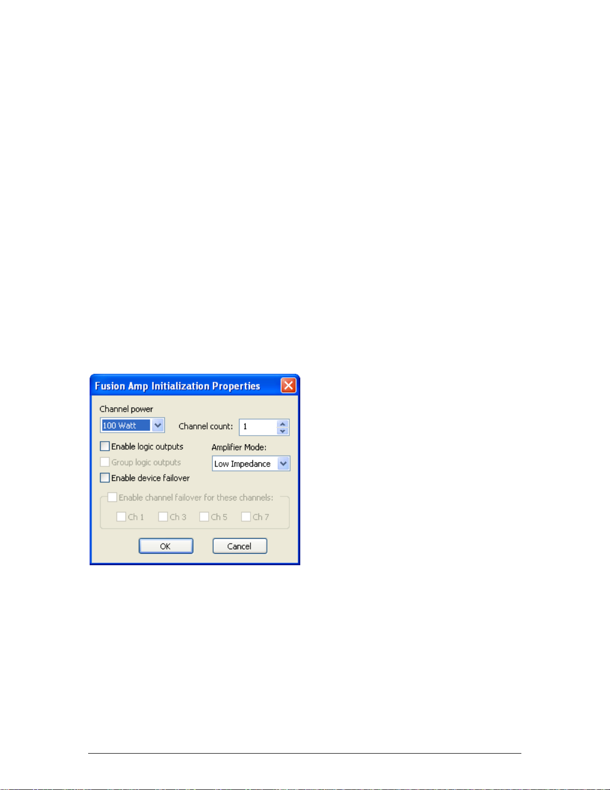
Initialization Properties
An AudiaFUSION unit appears in Audia software as an output block. When an AudiaFUSION
device is chosen from the I/O menu in the Object toolbar and the mouse is clicked in the layout
window, an AudiaFUSION Amp Initialization Dialog window appears.
Channel Power is used to select the power rating (in watts) for all channels controlled by that
block.
Channel Count is used to select the number of amplifier channels that block will provide. The
maximum number of channels available with this parameter is affected by the Channel power
setting. For example, a setting of 600 watts would result in a maximum Channel count of 4, as
600 watts x 4 channels = 2400 watts, which is the maximum amplifier capacity of one
AudiaFUSION frame.
Enable Logic Outputs is used to determine if the AudiaFUSION block will provide logic output
connection points.
1
Page 22

Audia-Manual-LTR
Group Logic Outputs is used when Enable logic outputs is checked to determine what
complement of logic outputs are provided on the AudiaFUSION block. If Group logic outputs is
unchecked, the block will feature six logic outputs per channel, plus a global Fan Stuck Rotor
output. The six logic outputs for each channel correspond to the six fault types that an
AudiaFUSION amplifier channel can report: Heat Sink, Short Circuit, Channel Failure, Excessive
Clipping, Low Impedance, and High Impedance.
If Group Logic Outputs is checked, only two logic outputs are provided per amplifier channel,
Alarm and Warning, plus the global Fan Stuck Rotor. In this mode, the Alarm output is a logical
OR of the Heat Sink, Short Circuit, and Channel Failure Alarms. The Warning output is a logical
OR of the Heat Sink, Excessive Clipping, Low Impedance, and High Impedance Warnings. If an
AudiaFUSION block is initialized with Device Failover active, two additional global logic outputs
are provided, Primary Device Good and Secondary Device Good.
Amplifier Mode is used to specify whether the amplifier channels controlled by that block will be
configured as Low Impedance – for standard 4, 6, or 8 Ohm loudspeakers – or 70V or 100V
Constant Voltage – for connection to distributed, transformer-coupled loudspeakers.
Enable Device Failover is used to establish an automatic device failover mode using two
identically configured AudiaFUSION units. The two units become a logical pair and are referred
to as the Primary Device and Secondary Device. If the Primary Device experiences an alarm, it
will automatically transfer control to the Secondary Device, which will continue to process and
distribute audio, taking on all of the functions of the Primary Device.
When device failover occurs, switching relays on the AM600 amplifier modules will physically
break loudspeaker connections on the Primary Device and make connections on the Secondary
Device. As a result, it is necessary to have two physical cable runs to each loudspeaker
connection, one from the Primary Device and one from the corresponding output channel on the
Secondary Device, in order for audio to continue to flow when device failover occurs.
When an AudiaFUSION block is created with Enable Device Failover checked, it will appear in
the layout window as two devices “fused” together. The properties and attributes of the
Secondary Device cannot be edited or modified independently of the Primary Device. The two
units are always configured identically.
When a layout is compiled that includes an AudiaFUSION block with device failover enabled, the
Secondary Device will receive a device ID that is different from the Primary Device; however,
during a failover, any received ATP command strings intended for the Primary Device are
automatically routed to the Secondary Device, and any acknowledgement messages that the
Secondary Device returns will contain the device ID of the Primary Device, even though the
Primary Device is no longer the active unit. This preserves third-party control support during
device failover.
A device failover pair will appear in the Equipment Table with device types that are read-only. If
either the Primary or Secondary Device is removed from the Equipment Table, the partner unit
will also be removed.
Enable Channel Failover for these Channels provides a means of establishing an automatic
channel failover mode using two adjacent channels within a single AudiaFUSION unit. The two
designated channels become a logical pair and are referred to as Primary Channel and
Secondary Channel. If the Primary Channel experiences a channel alarm, it will automatically
transfer control to the Secondary Channel, which will continue to process and distribute audio,
taking on all of the functions of the Primary Channel.
When channel failover occurs, switching relays on the AM600 amplifier modules will physically
break loudspeaker connections on the Primary Channel and make connections on the Secondary
Channel. As a result, it is necessary to have two physical cable runs to each loudspeaker
connection, one from the Primary Channel and one from the Secondary Channel, in order for
audio to continue to flow when channel failover occurs.
2
Page 23
Introduction
When failover occurs, any received ATP command strings intended for the Primary Channel are
automatically routed to the Secondary Channel, and any acknowledgement messages that the
Secondary Channel returns will contain the index value of the Primary Channel, even though the
Primary Channel is no longer the active channel. This preserves third-party control support
during channel failover.
Note: Channel failover is not available when Device failover is being used, and vice versa.
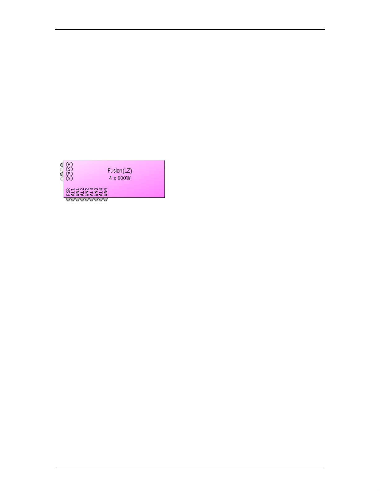
AudiaFUSION Block
The AudiaFUSION block provides connection points for audio coming into the block, and logic
output connection points for fault indications.
If channel failover is in use, the Primary Channel will be indicated with (P) and the Secondary
Channel with (S). The connection point for the Secondary Channel will appear in a light gray
color and will not accept a wire connection. Instead, the audio signal connected to the Primary
Channel will automatically be used as the input for the Secondary Channel when channel failover
occurs.
If device failover is in use, the block will appear as two AudiaFUSION blocks “fused” together.
The Primary (left) side will have the audio and logic connection points and the Secondary (right)
side will have no connection points.
The complement of logic output connection points that are available is dependent on whether the
Group Logic Outputs property in the AudiaFUSION block initialization dialog window is checked
or not. When that setting is unchecked, the block will feature six logic outputs per channel, plus a
global Fan Stuck Rotor output. The six logic outputs for each channel correspond to the six fault
types that an AudiaFUSION amplifier channel can report: Heat Sink, Short Circuit, Channel
Failure, Excessive Clipping, Low Impedance, and High Impedance.
If Group Logic Outputs is checked, only two logic outputs are provided per amplifier channel,
Alarm and Warning, plus the global Fan Stuck Rotor. In this mode, the Alarm output is a logical
OR of the Heat Sink, Short Circuit, and Channel Failure Alarms. The Warning output is a logical
OR of the Heat Sink, Excessive Clipping, Low Impedance, and High Impedance Warnings. When
the AudiaFUSION block is initialized with Device Failover active, two additional global logic
outputs are provided, Primary Device Good and Secondary Device Good.
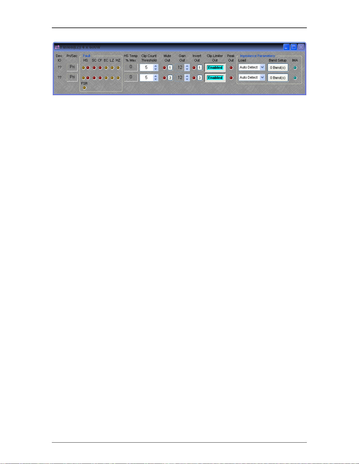
AudiaFUSION Control Dialog Window
3
Page 24
Audia-Manual-LTR
Device I/O indicates which hardware input is associated with that software channel. If Device
failover or Channel failover is in use, an additional column to the right of the Device I/O field will
indicate whether that device or channel is Primary (Pri) or Secondary (Sec).
Fault
There are two types of Faults that the AudiaFUSION can report, categorized as Warnings or
Alarms, depending on their severity. A Warning indicates that some aspect of the system is not
performing within normal specification. Audio is still passing, but if the condition causing the
Warning is not corrected, failure may occur. An Alarm indicates that some aspect of the system
has failed and audio is no longer passing on that channel. If Channel or Device Failover has
been enabled for that channel or device, an Alarm will cause failover to occur, whereas a
Warning will not.
List of AudiaFUSION Faults:
Heat Sink (HS) Warning indicates that the heat sink on the AM600 amplifier module has
reached 92% of its maximum cooling capacity. The amplifier module will automatically
attenuate audio by 3 dB to attempt to reduce the temperature of the heat sink. If the
temperature continues to rise, the HS Warning will become an HS Alarm (see below).
The heat sink temperature must fall below 84% of maximum capacity to clear the HS
Warning and restore full output level.
Heat Sink (HS) Alarm indicates that the heat sink on the AM600 amplifier module has
reached 100% of its cooling capacity and audio on that channel will be stopped. Failover
will occur if enabled on that channel or device. If failover is not enabled, audio will only
be restored on that channel when the heat sink temperature falls below 84% of maximum
capacity.
Short Circuit (SC) Alarm indicates that there may be a short circuit on the load on that
channel. The output current of the amplifier module is continuously monitored. If the
current exceeds the maximum rated current amount, or if the load impedance monitoring
circuit calculates an effective load of 1 Ohm or less, the SC Alarm will occur and audio
will be stopped on that channel. After a brief wait, the amplifier module will attempt to
restart audio. If the condition that caused the SC Alarm persists, the amplifier module will
continue to wait and try again. It will do this indefinitely, unless failover has been enabled
on that channel or device, in which case the Short Circuit Delay attribute in the Property
Sheet of the AudiaFUSION block will determine how long the amplifier module will retry
before failover occurs.
4
Page 25

Introduction
Channel Failure (CF) Alarm indicates that a hardware failure of the amplifier module
has occurred. Audio will be stopped on that channel and channel or device failover will
occur, if enabled.
Excessive Clipping (EC) Warning indicates that amplifier output clipping has occurred
(or would have occurred if the Clip Limiter had not been enabled) and is affected by the
Clip Count Threshold parameter (see Clip Count Threshold below).
Low Impedance (LZ) Warning indicates that the impedance monitoring circuit (if
enabled) has detected an impedance that is lower than the minimum allowed by the
current setting of the Tolerance parameter (see Band Setup below).
High Impedance (HZ) Warning indicates that the impedance monitoring circuit (if
enabled) has detected an impedance that is higher than the maximum allowed by the
current setting of the Tolerance parameter (see Band Setup below).
Other Control Dialog Parameters
HS Temp % Max indicates the temperature of the heat sink located on the amplifier module,
given as a percentage of maximum cooling capacity. If the heat sink temperature rises to 92%, a
Heat Sink (HS) Warning will occur and the amplifier module will attenuate its output by 3 dB to
attempt to reduce the temperature of the heat sink. If the heat sink temperature rises to 100%, a
Heat Sink (HS) Alarm will occur and audio on that channel will be stopped.
Clip Count Threshold is the number of consecutive 100 ms segments of audio containing at
least one clipped sample that are needed to illuminate the Excessive Clipping (EC) Warning
indicator. The Clip Count Threshold affects the response of the EC Warning indicator; if the Clip
Count Threshold is set to 1, the Excessive Clipping (EC) Warning indicator becomes a “standard”
or instantaneous clip indicator, rather than an “excessive” or long-term clip indicator.
Mute Out is used to mute the audio on that channel. Gain Out (dB) is used to set the amplifier
sensitivity. This control ranges from 0 dB (unity gain) to 24 dB (default is 12 dB). Invert Out is
used to reverse the polarity of the output signal. Clip Limiter Out is used to control whether the
analog clip limiting circuit on the amplifier module is enabled or not. When enabled, this limiter
attenuates any signal peaks that would otherwise cause the amplifier’s output to clip. Peak Out
is a signal peak indicator that illuminates when the output signal is within 3 dB of clipping the
amplifier.
Impedance Parameters
Load is a setting that allows the user to select the intended speaker load (4, 6, or 8 Ohm) for all
channels controlled by that block. Choosing Auto Detect will allow the AM600 amplifier module to
automatically set the load impedance based upon the amplifier output current. This setting is only
available if the Amplifier Mode has been designated as Low Impedance. (See Amplifier Mode
above)
Band Setup produces a control dialog window that allows the Impedance Monitoring algorithm to
be configured. The text on the button control will indicate the number of frequency bands that
have been defined for impedance monitoring.
Impedance Monitoring Active (IMA) is an indicator that illuminates when impedance monitoring
is active.
Frequency Band Setup
5
Page 26

Audia-Manual-LTR
Frequency Band Setup is a dialog window that contains parameters for defining frequency
bands over which impedance monitoring should occur. Up to four bands can be defined. Active
Band is used to choose which band’s parameters are displayed for modification. Center Freq
(Hz) is the center frequency of the active band. Bandwidth (Hz) is the bandwidth of the active
band. Tolerance % defines the amount above or below the baseline impedance curve that,
when exceeded, causes a High Impedance or Low Impedance Warning to occur. Setting
Tolerance % to a lower number means that a smaller change in the load impedance curve will be
sufficient to cause a High Impedance or Low Impedance Warning. Setting Tolerance % to a
higher number means that a larger change in the load impedance curve will be required to cause
a High Impedance or Low Impedance Warning.
Add Band is used to add an additional band to the monitoring algorithm. Up to four bands can
be defined. Remove Band will delete the highest-numbered band. Disable Alarms is used to
bypass the impedance monitoring algorithm and suppress any High Impedance or Low
Impedance faults that may be detected. Averaging length (samples) defines the number of
impedance measurements that are collected and averaged to determine the load impedance
curve. Setting this value to a lower number will allow the curve to be drawn and updated more
quickly, at the expense of some accuracy or “curve jitter.” Setting this value to a higher number
will cause the curve to be drawn and updated more slowly, but with smoother and more accurate
data.
Capture Alarm Baseline Data is used to populate the Alarm Baseline Data fields with the
currently displayed Realtime Impedance Data. The Realtime Impedance Data is obtained by
dynamically measuring load voltage versus current at several different frequencies throughout the
audible spectrum. The results of this impedance calculation are affected by the amplitude and
spectral characteristics of the signal passing through the amplifier module. For best results, a
wideband signal such as pink noise should be played at a sufficient level to overcome the noise
floor of the detection circuitry.
Impedance Monitoring Active is an indicator that illuminates when sufficient data has been
entered for the impedance monitoring algorithm to begin monitoring that band.
Auto Mixer Combiner
Note: The Auto Mixer Combiner replaces the Mix Minus Combiner in the software and incorporates all of its functionality,
plus some additional features. Files created in previous versions of Audia that contain a Mix Minus Combiner will still
function normally and the Mix Minus Combiner will still appear in the layout, even though the block will no longer appear in
the Object Toolbar or Processing Library. The user may substitute an Auto Mixer Combiner block anywhere a Mix Minus
Combiner would have been used.
6
Page 27
Introduction
Auto Mixer Combiner blocks enhance the capabilities of Auto Mixers in room
combining, mix-minus, and input expansion applications. Auto Mixer Combiners
combine control data only and, therefore, have no audio outputs. Inputs to an Auto
Mixer Combiner come from the Mix outputs of separate Auto Mixer blocks. Ch /
Combine allows input channels (1, 2, 3, etc.) to be grouped into specific combinations
(A, B, C, etc.). These combinations automatically determine proper routing of control
data for the Auto Mixer blocks. Control data represents NOM (number of open mics),
ATS (adaptive threshold sensing), and last mic hold status information. Auto Mixer
Combiners are used when Auto Mixer outputs are also connected to a separate Matrix
Mixer (to create multiple mix-minus outputs). Auto Mixer Combiners allow large Auto
Mixers to be created from multiple, smaller ones. This is useful when more than 32
inputs are required or when an Auto Mixer must be placed into multiple Audia units (for
proper DSP allocation or physical location of inputs).
Groups buttons are used to choose a group for viewing and editing two settings: Last
Mic Hold and Open Mic Limits. Last Mic Hold determines whether the last open
microphone across all Auto Mixer inputs assigned to the current group is allowed to
gate off when activity on that channel ceases. Open Mic Limits enables (and
designates) a maximum allowable number of active microphones across all Auto Mixer
inputs assigned to the current group.
Right clicking on Ch / Combine assignments will prompt a menu of additional options.
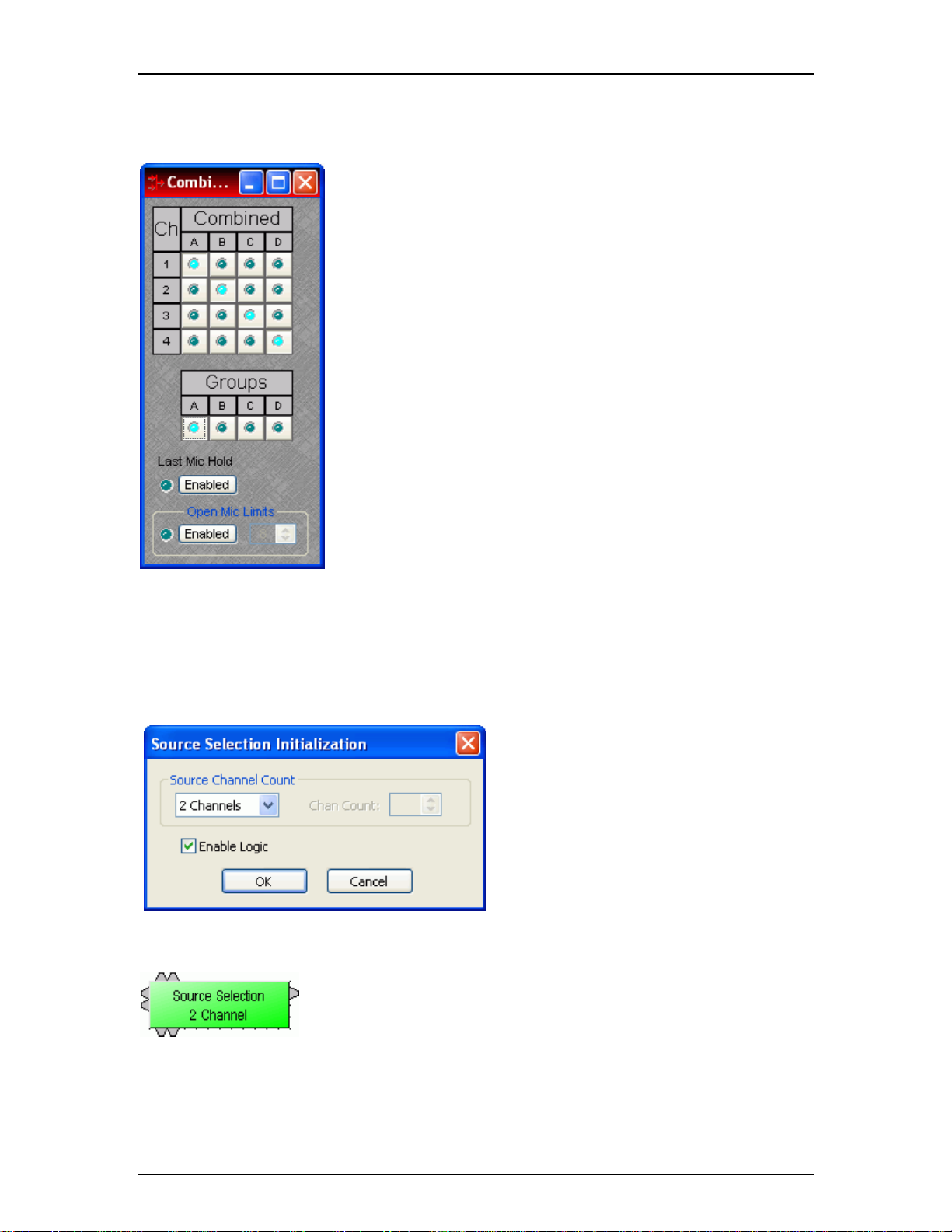
Source Selections
Source Selection blocks are N by 1 routers (where N represents the number of sources) with level control per input and
optional logic input and output connections. Source Selection blocks are useful when remote control of audio source
selection is required.
When the user first places a Source Selection
block into an Audia layout, this prompts an
initialization window.
Source Channel Count specifies the number of input
channels (2 to 16) and generally corresponds to the
number of sources from which the user can choose. If the
Source Channel Count is set to Custom, the Chan Count
parameter is used to specify the exact number of
channels desired.
If selected, Enable Logic provides a logic input and output
connection point for each channel.
Source Selection is represented in the layout
as a block with a number of audio input
connections (specified by the Source Channel
Count parameter), one audio output
connection, and optionally, a logic input and
output connection point for each channel. If
logic is enabled, a low-to-high logic transition
(i.e., a rising edge) presented to a logic input
7
Page 28
Audia-Manual-LTR
RED-1
connection will cause the Source Selection
block to switch to the corresponding audio
input channel, and the corresponding logic out
connection will be at a logic high. All other
logic outputs will be low.
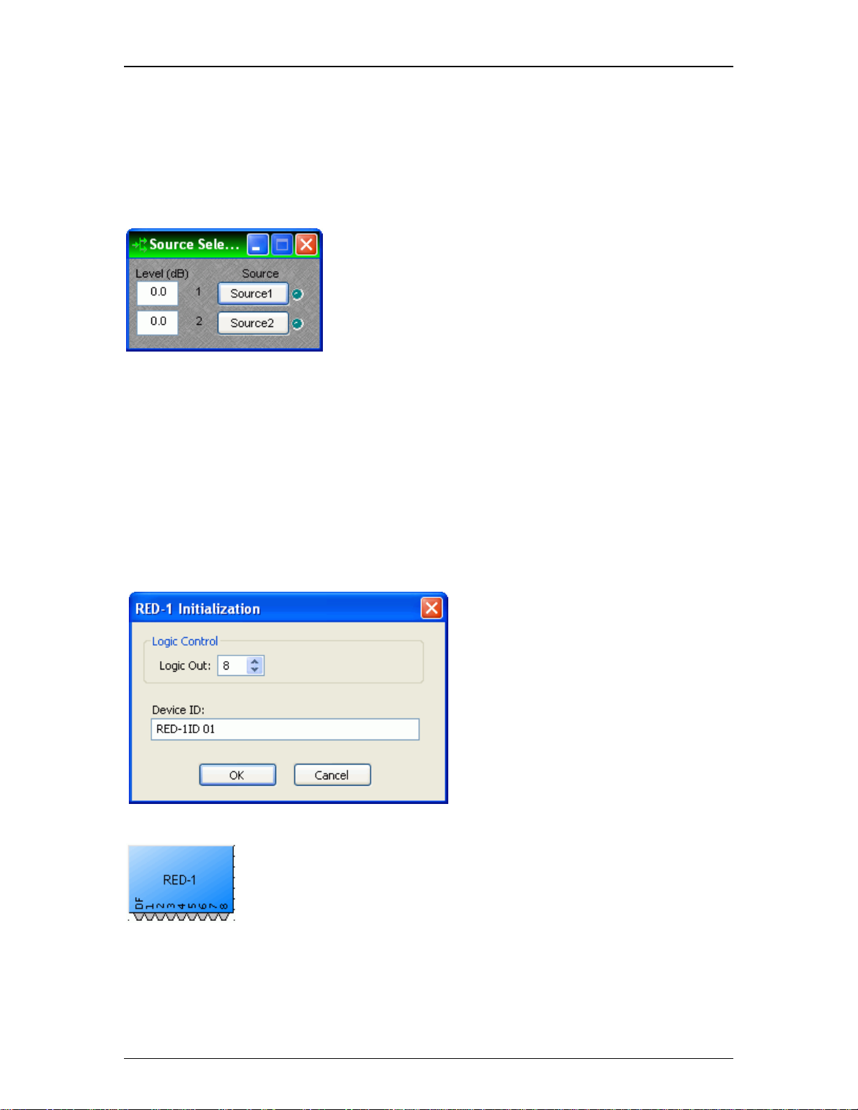
Double clicking on a Source Selection block produces a
control window.
Level (dB) adjusts the level (-100 to 12 dB) of the source
connected to that channel’s input.
Source Selection buttons are used to select the input
source that is routed to the audio output connector of the
Source Selection block. If the user right clicks a source
selection button, this produces a dialog box that allows
customization of the text that is displayed on that button.
This dialog box can be minimized to create user control
surfaces (see Customizing Component Objects).
Remote Ethernet Device 1 (RED-1) is an external remote control panel that integrates with Audia systems via Ethernet,
using a single CAT5 cable for control and Power-over-Ethernet (PoE). RED-1 allows for the selection of up to 32 control
items. A control item can be the initiation of a logic event (such as a preset recall or a source selection), selection of a
volume assignment, or both. Volume assignments may be individual or ganged levels within the layout, including Level
Control blocks, as well as levels within other component blocks (such as Input/Output blocks, Mixers, Equalizers, etc).
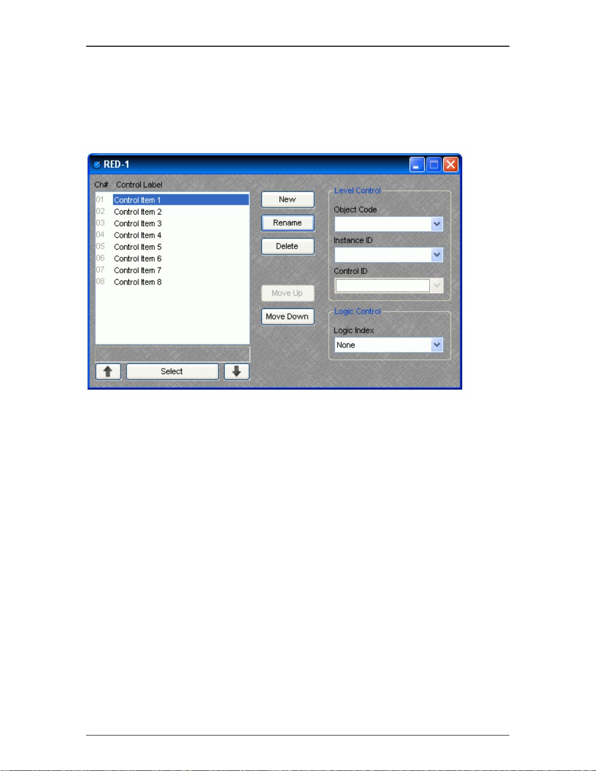
When a RED-1 block is first placed into the layout, an
initialization dialog box appears.
Logic Out specifies the number of logic connection
points (0 to 32) on the RED-1 block. These connection
points are typically wired to Remote Preset or Source
Selection blocks but can also be used as generalpurpose logic inputs.
Device ID is the name given to each RED-1 block and
should correspond to the Device ID of a physical remote
panel. No two RED-1 blocks in any layout may have the
same Device ID; however, multiple RED-1 panels may
have the same Device ID. In that case, the panels’
functions are identical and governed by the RED-1
block with the corresponding Device ID.
RED-1 is represented in the layout as a
block with a number of logic connection
points (determined by the Logic Out setting
when the block is created), plus a DF logic
output node, which outputs logic high when
at least one like-named RED-1 unit is
discovered on the network.
8
Page 29
Introduction
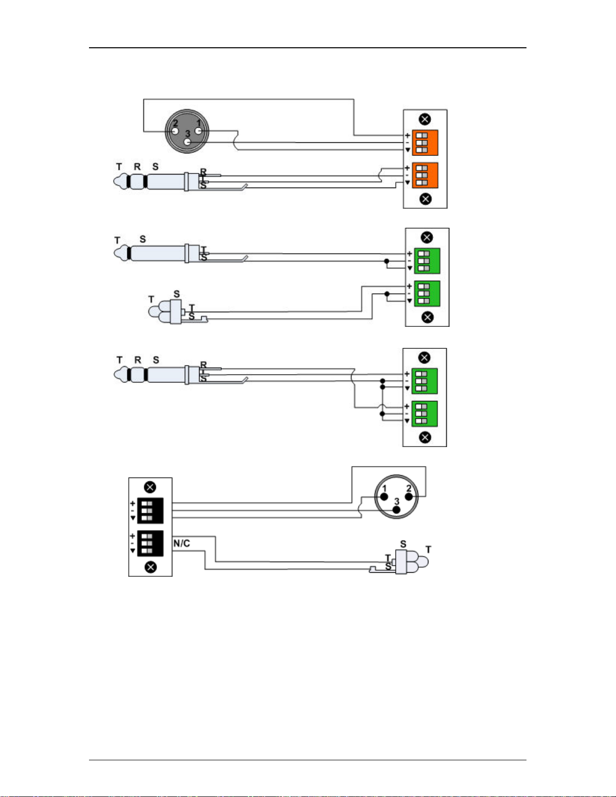
All programmed panel functions are assigned using the control dialog box, which is produced by double-clicking the RED1 block.
A list displays all defined control items, each with a Channel Number and customizable Control Label. The New button
creates a control item in the list, and the user is prompted to either accept the default label or enter a new one. Rename
allows the user to change the Control Label of the selected control item. Delete removes the selected control item from
the list. Move Up and Move Down modify the order of the control items in the list, giving the user the ability to control the
display order of the control items on the RED-1 panel.
Each control item may have a Level Control assignment, a Logic Control assignment, or both.
Level Control
Object Code selects from a list of blocks found in the layout, and the Instance ID is entered automatically, if known.
Control ID selects from a list of available levels within the chosen block.
Logic Control
Logic Index specifies which logic connection point, if any, on the RED-1 block will be triggered when that control item is
selected.
Once the RED-1 block has been programmed with control items, the Select and Up/Down Arrow buttons at the bottom of
the control dialog box may be used to mimic how the control will function from the physical panel.
Control dialog boxes for RED-1 devices may be minimized to create user control surfaces (see Customizing Component
Objects).
Audio Wiring Diagrams
9
Page 30
Audia-Manual-LTR
AEC-2HD
Balanced
IP-2
Un-
balanced
IP-2
Un-
balanced
stereo to
two un-
balanced
inputs
OP-2e
Balanced
Output
Un-
balanced
Output
10
Page 31

Introduction
PA-2
Speaker
output
4Ω or 8Ω
PA-2
Speaker
output
Bridged-
Mono
Mode
4Ω or 8Ω
Telephone
Interface.
Note That
Two Telco
Lines Are
Used In
This
Example
But Not
Required.
Local
Telephone
s Are Not
Required
For
System
To
Function
But Can
Be Used
As Dialers
Or Local
Monitors.
VoIP Blocks
VoIP Console Attribute Commands Index Value Range
11
Page 32

Audia-Manual-LTR
Hookstate VOIPHOOKSTATE SET, GET 1
Digit(s) to Dial VOIPPHONENUM DIAL 1
Last Number Dialed VOIPLASTNUM GET 1 None
Redial VOIPLASTDIALED DIAL 1 None
Speed Dial
Tel. Number
Speed Dial
Name
Speed Dial
Entry to Dial
Answer Call VOIPCALL ANS 1 None
Reject or End Call VOIPCALL END 1 None
Auto-Answer VOIPAAENABLE SET, GET 1
Number of Rings
Before AutoAnswer
Place a Call on Hold VOIPCALL HOLD 1 None
Resume a Call on
Hold
VOIPSDENTRY SET, GET 1 & 2
VOIPSDLABEL SET, GET 1 & 2 enter the name
VOIPSPEEDDIAL DIAL 1 1 ~ 16
VOIPAACOUNT SET, GET 1 0, 1, 2, 3, 4, 5
VOIPCALL RESUME 1 None
0 = off-hook
1 = on-hook
enter the phone
number
enter the phone
number
0 = enabled
1 = disabled
Line In Use State VOIPLIUSTATE GET 1
Line Ready State VOIPLRSTATE GET 1
Ring Indicator State VOIPRISTATE GET 1
CallerID VOIPCIDUSER GET 1 "date""phnenum'"name"
0 = not in use
1 = in use
0 = not ready
1 = ready
0 = not ringing
1 = ringing
Note: Index 1 is the line number [1,2] and index 2 is the speed dial entry [1,16].
Multiple VOIPPHONENUM commands can be used to dial the individual digits of a phone
number, but the VoIP dialer must store the complete dial string and send it in a single request to
the VoIP Proxy. To accomplish this task, it must be aware of the end of the dial string. To indicate
the end of a dial string, include a # symbol in the dial command (DIAL 1 VOIPPHONENUM 104 1
5551234#) or (DIAL 1 VOIPPHONENUM 104 1 #).
A dialing timeout also signals the end of a dial string. If the phone is on hook, the first DIAL
command will automatically set the hook state of the line to off hook. Once off hook, the dialing
sequence will time out if a new digit is not received within 3 seconds (configurable). Once this
timeout occurs, the call will be placed using the existing digits.
12
Page 33

Introduction
DIAL commands received after the call is connected are sent immediately (as DTMF tones). The
dialer can insert delay while sending DTMF tones by inserting commas where desired (each
comma provides ½ second of delay).
Redial and Speed Dial numbers are assumed to be complete dial strings and do not require # (or
wait for a dialing timeout) to be sent. Redial includes only the dial string used to connect the
previous call and does not include DTMF tones sent during the connection.
Both ANS 1 VOIPCALL 104 1 and SET 1 VOIPHOOKSTATE 104 1 0 will answer an incoming
call. Both END 1 VOIPCALL 104 1 and SET 1 VOIPHOOKSTATE 104 1 1 will end a call in
progress.
VoIP Receive Attribute Commands Index Value Range
Receive Level VOIPRXLVL
CPT Level VOIPRXCPTLVL
Mute VOIPRXMUTE SET, GET 1
SET, SETL, GET, GETL,
INC, DEC
SET, SETL, GET, GETL,
INC, DEC
1 -100 ~ 12 *
1 -100 ~ 0 *
0 = unmuted
1 = muted
* Can contain a decimal number.
VoIP Transmit Attribute Commands Index Value Range
Transmit Level VOIPTXLVL
Mute VOIPTXMUTE SET, GET 1
SET, SETL, GET, GETL,
INC, DEC
1 -100 ~ 0 *
0 = unmuted
1 = muted
* Can contain a decimal number.
Device Attribute Commands Index Value Range
VoIP FW Ver VOIPFWVER GET None Major.Minor (ex: 1.90)
Device FQ Ver DEVFWVER GET None (ex: 3.307-2.3-4.510)
13
Page 34

Audia-Manual-LTR
Below are some examples of possible string usage:
1. Basic Dialing with timeout to send, talk, and then end call locally with end command
SET 0 VOIPHOOKSTATE 104 1 0 // go off hook
DIAL 1 VOIPPHONENUM 104 1 1 // dial the digit 1
DIAL 1 VOIPPHONENUM 104 1 2 // dial the digit 2
DIAL 1 VOIPPHONENUM 104 1 3 // dial the digit 3
// … 3 seconds pass (from last DIAL) and
request is sent
// … Talking...
END 1 VOIPCALL 104 1
2. Basic Dialing with explicit send and end call locally with end command
DIAL 1 VOIPPHONENUM 104 1 1 // go off hook and dial the digit 1
DIAL 1 VOIPPHONENUM 104 1 2 // dial the digit 2
DIAL 1 VOIPPHONENUM 104 1 3 // dial the digit 3
DIAL 1 VOIPPHONENUM 104 1 # // send the dial request to the VoIP Proxy
// … Talking...
END 1 VOIPCALL 104 1
3. Incoming call & answer and end locally
// incoming call (ringing…)
ANS 1 VOIPCALL 104 1 // answer call
// … Talking...
14
Page 35

END 1 VOIPCALL 104 1
4. Incoming call & answer and end locally
// incoming call (ringing…)
SET 1 VOIPHOOKSTATE 104 1 0 // answer call
// … Talking...
END 1 VOIPCALL 104 1
5. Incoming call & reject
// incoming call (ringing…)
END 1 VOIPCALL 104 1 // reject call
Introduction
6. Incoming call & answer, Place call on hold, resume call, and end locally
// incoming call (ringing…)
ANS 1 VOIPCALL 104 1 // answer call
// … Talking...
HOLD 1 VOIPCALL 104 1 // place call on hold
RESUME 1 VOIPCALL 104 1 // resume call
// … Talking...
END 1 VOIPCALL 104 1
Features
15
Page 36

Audia-Manual-LTR
Audia is a Digital Audio Platform, which provides distributed digital audio, signal processing, and
control.
Audia is a networkable, decentralized audio system, which is easy to configure & program.
Audia allows the installer to quickly & accurately define the exact sound system required for each
job.
Audia is software programmable, easily expandable, and remotely controllable.
Audia utilizes both CobraNet® and Ethernet for enhanced system networking and control.
Audia is a completely customizable, yet cost-effective, solution for sound system design.
Audia is covered by a five-year warranty.
ALGORITHMS
Mixers: standard, automatic, matrix, combiners
Equalizers: graphic, parametric, feedback
Filters: HPF, LPF, high shelving, low shelving, all-pass
Crossovers: 2-way, 3-way, 4-way
Dynamics: levelers, comp/limiters, duckers, gates, ambient noise compensators
Routers: 2x1 to 56x56
Delays: 0 to 2,000 ms
Controls: levels, mutes, presets, remotes, logic, command strings, event schedules
Meters: signal present, peak reading, RMS reading
Generators: single tone, sweep, pink-noise, white-noise
Diagnostics: transfer function
HARDWARE:
24-bit A/D & D/A converters
16
Page 37

Introduction
Six 60 MHz 32-bit floating point Analog Devices SHARC DSPs (360 MFLOPS)
80 MHz 32-bit Motorola Power PC host processor
32 Mbytes SDRAM
8 Mbytes Flash ROM
Ethernet communications for software control and configuration
Support of TCP/IP, UDP and ICMP (ping) networking standards
Battery backed real-time clock and calendar
Powered Remote Control Bus for easy addition of AUDIA control devices; touch
screens, rotary encoders, and contact switches
RS-232 serial port for simple connection to 3rd party control devices
Internal 80 watt universal switching power supply
Multiple analog I/O configurations
Mic/Line inputs with programmable mic preamp (0dB to ~ +66dB gain)
Optional CobraNet interface supporting 64 channels of digital audio (32 in/32 out)
Compatible with all other CobraNet compliant devices
Works with standard Ethernet switches
Multiple system-wide presets and current settings stored in flash memory
Layout drawing information stored in flash memory
SOFTWARE:
Win32 application: Windows® XP Professional/Vista operating system required
Fully dockable Menu and Toolbar support
Birdseye viewer for easy panning and zooming of large layout files
Fully customizable Processing Library bar for storing default and custom DSP objects
Workspace state saved at program shutdown, including current documents, Toolbar,
over Fast Ethernet
Catalog & Birdseye viewer states
User configurable data file and Processing Library catalog
Simple object attribute control: colors, line widths, hatching, text font, size, style &
alignment, border widths, etc.
Multiple simultaneous line (wire) drawing with no special editing modes required
17
Page 38

Audia-Manual-LTR
Special text block object to enter freeform text and label information
Easy-to-use tools for object alignment, sizing, packing, spacing & centering
Fully supported object drag-and-drop between Catalog and view, and between views
Fully supported multiple layers within a drawing
Support of Clipboard operation
Programmable presets
Export file types: DXF (drawing interchange format) & EMF (enhanced meta files)
Architect's & Engineer's Specifications
AUDIA® Digital Audio Platform
ARCHITECTS & ENGINEERS SPECIFICATION (January 1, 2002)
The Digital Audio Platform shall be available in three hardware
configurations: 8-in/8-out (8x8); 12-in/4-out (12x4); and 4-in/12-out
(4x12). Inputs and outputs shall be analog, with internal 24-bit A/D &
D/A converters operating at a sample rate of 48kHz. All internal
processing shall be digital (DSP). Electronically balanced inputs and
outputs shall be provided on plug-in barrier-strip connectors. Inputs
shall be individually programmable to accept either microphone or line
level signals. The 12x4 configuration shall allow inputs 11 & 12 to be
set for mono summing of unbalanced stereo line level signals. Outputs
shall normally provide line level signals, however, the 4x12
configuration shall allow outputs 1~4 to be individually programmed to
provide microphone level signals.
Each hardware configuration shall include six 60MHz 32-bit floating
point SHARC DSPs, an 80MHz 32-bit Power PC host processor, 32MB SDRAM,
and 8MB Flash ROM. Software shall be provided for creating/connecting
DSP system components within each hardware unit. Available system
components shall include (but not be limited to) various forms of:
mixers, equalizers, filters, crossovers, dynamics/gain controls,
routers, delays, level controls, level meters, and tone generators.
Ethernet communications shall be utilized for software control,
configuration, and DSP sharing. CobraNet® technology shall transport
digital audio over fast Ethernet, allowing multiple units to share
digital audio. After initial programming, systems may be controlled
using either TCP/IP or RS-232 serial communication by third party
control systems such as AMX® and Crestron®.
Each hardware configuration shall be available with CobraNet (for
multi-unit network applications) or without CobraNet (for stand-alone
applications). Multi-unit network applications require an external
10/100Base-T Ethernet switch. All CobraNet & Ethernet connections shall
be via CAT5 cable or fiber-optic. Software shall operate on a PC
computer, with network card installed, running Windows® XP
Professional/Vista.
18
Page 39

Introduction
The Digital Audio Platform shall be AUDIA®.
AudiaSOLO Digital Audio Platform
ARCHITECT'S & ENGINEER'S SPECIFICATION
The Digital Audio Platform shall be available in three hardware
configurations: 8-in/8-out (8x8); 12-in/4-out (12x4); and 4-in/12-out
(4x12). Inputs and outputs shall be analog, with internal 24-bit A/D &
D/A converters operating at a sample rate of 48kHz. All internal
processing shall be digital (DSP). Electronically balanced inputs and
outputs shall be provided on plug-in barrier-strip connectors. Inputs
shall be individually programmable to accept either microphone or line
level signals. The 12x4 configuration shall allow inputs 11 & 12 to be
set for mono summing of unbalanced stereo line level signals. Outputs
shall normally provide line level signals, however, the 4x12
configuration shall allow outputs 1~4 to be individually programmed to
provide microphone level signals.
Each hardware configuration shall include six 60MHz 32-bit floating
point DSPs, an 80MHz 32-bit host processor, 32MB SDRAM, and 8MB Flash
ROM. Software shall be provided for creating/connecting DSP system
components within each hardware unit. Available system components shall
include (but not be limited to) various forms of: mixers, equalizers,
filters, crossovers, dynamics/gain controls, routers, delays, remote
controls, meters, generators, and diagnostics. Ethernet communications
shall be utilized for software control and configuration. After initial
programming, systems may be controlled using either TCP/IP or RS-232
serial communication by third party control systems (such as AMX® and
Crestron®), by PC computer, and/or by dedicated remote control devices.
Software shall operate on a PC computer, with network card installed,
running Windows® XP Professional/Vista. The Digital Audio Platform
shall be CE marked, UL/C-UL listed, and carry a five-year warranty.
The Digital Audio Platform shall be AudiaSOLO.
AudiaFLEX Digital Audio Platform
ARCHITECT'S & ENGINEER'S SPECIFICATION
The Digital Audio Platform shall be available in various I/O
configurations. Inputs/outputs shall be specified in pairs, up to a
total of 24. Mic/line Input (IP-2), Acoustic Echo Cancellation (AEC2HD), Telephone Interface (TI-2), Mic/Line Ouput (OP-2e), and Amplifier
Ouput (PA-2) input/output options shall be available. Inputs/outputs
shall be analog, with internal 24-bit A/D & D/A converters operating at
a sample rate of 48kHz. All internal processing shall be digital (DSP).
Electronically balanced inputs and outputs shall be provided on plug-in
barrier-strip connectors. Inputs and outputs shall be individually
programmable for either microphone or line level signal. Expansion
units, utilizing CobraNet®, shall be available in 8-channel versions,
for adding analog or digital inputs/outputs to a system.
19
Page 40

Audia-Manual-LTR
Each hardware configuration shall include six 60MHz 32-bit floating
point DSPs. Software shall be provided for creating/connecting DSP
system components within each hardware unit. Available system
components shall include (but not be limited to) various forms of:
mixers, equalizers, filters, crossovers, dynamics/gain controls,
routers, delays, remote controls, meters, generators, and diagnostics.
Ethernet communications shall be utilized for software control,
configuration, and DSP distribution. Each hardware configuration shall
be available with CobraNet (for multi-unit applications) or without
CobraNet (for stand-alone applications). CobraNet technology shall
transport digital audio over fast Ethernet, allowing multiple units to
share digital audio. Multi-unit applications shall require an external
10/100Base-T Ethernet switch. All CobraNet and Ethernet connections
shall be via CAT5 cable or fiber-optic. After initial programming,
systems may be controlled using either TCP/IP or RS-232 serial
communication by third party control systems (such as AMX® and
Crestron®), by PC computer, and/or by dedicated remote control devices.
Software shall operate on a PC computer, with network card installed,
running Windows® XP Professional/Vista. The Digital Audio Platform
shall be CE marked, UL/C-UL listed, and shall incorporate AES48-2005
Grounding & EMC practices. The Digital Audio Platform shall be
compliant with EU Directive 2002/95/EC, the RoHS directive. Warranty
shall be 5 years.
The Digital Audio Platform shall be AudiaFLEX.
AudiaEXPI Input Expander
ARCHITECT'S & ENGINEER'S SPECIFICATION
The Input Expander shall provide eight mic/line analog audio inputs on
rear panel plug-in barrier strip connectors. Front panel level controls
and peak indicators shall be provided for adjustment of the analog
audio input signals. Internal analog-to-digital signal conversion shall
be 24-bit, with a sample rate of 48kHz. Eight channels of digital audio
output shall be provided via CobraNet®, on two rear panel RJ45
connectors. A rotary encoder and LCD screen shall be provided on the
front panel for programming and setup.
The Input Expander shall be represented as a functional block within
AUDIA® software, for easy inclusion into system designs. The Input
Expander shall also be capable of providing additional analog audio
inputs to other CobraNet compliant systems or devices. The Input
Expander shall be CE marked, include a UL listed power source, and
carry a five-year warranty.
The Input Expander shall be AudiaEXPI.
20
AudiaEXPO Output Expander
ARCHITECT'S & ENGINEER'S SPECIFICATION
Page 41

Introduction
The Output Expander shall provide eight channels of digital audio input
via CobraNet®, on two rear panel RJ45 connectors. Internal digital-to-
analog signal conversion shall be 24-bit, with a sample rate of 48kHz.
Eight line-level analog audio outputs shall be provided on rear panel
plug-in barrier strip connectors. Front panel level controls shall be
provided for adjustment of the analog audio output signals. A rotary
encoder and LCD screen shall be provided on the front panel for
programming and setup.
The Output Expander shall be represented as a functional block within
AUDIA® software, for easy inclusion into system designs. The Output
Expander shall also be capable of providing additional analog audio
outputs from other CobraNet compliant systems or devices. The Output
Expander shall be CE marked, include a UL listed power source, and
carry a five-year warranty.
The Output Expander shall be AudiaEXPO.
AudiaEXPI-D Digital Input Expander
ARCHITECT'S & ENGINEER'S SPECIFICATION
The Digital Input Expander shall provide four pairs of AES3 transformer
coupled digital audio inputs on XLR connectors. Two of these pairs
shall be selectable instead as SPDIF inputs on RCA connectors and the
other two pairs shall be selectable instead as TOSLINK inputs. Eight
channels of digital audio output shall be provided via CobraNet®, on
two rear panel RJ45 connectors. A word clock output shall be provided
on BNC connector. A rotary encoder and LCD screen shall be provided on
the front panel for programming and setup. Logic Inputs shall be
provided for recalling preset configurations.
The Digital Input Expander shall be represented as a functional block
within AUDIA® software, for easy inclusion into system designs. The
Digital Input Expander shall also be capable of providing digital audio
inputs to other CobraNet compliant systems or devices. The Digital
Input Expander shall be CE marked, include a UL listed power source,
and carry a five-year warranty.
The Digital Input Expander shall be AudiaEXPI-D.
AudiaEXPO-D Digital Output Expander
ARCHITECT'S & ENGINEER'S SPECIFICATION
The Digital Output Expander shall provide eight channels of digital
audio input via CobraNet®, on two rear panel RJ45 connectors. Four
pairs of AES3 transformer coupled digital audio outputs shall be
provided on XLR connectors. Two of these pairs shall be available also
as SPDIF outputs on RCA connectors, and the other two pairs shall be
available also as TOSLINK outputs. A word clock output shall be
provided on BNC connector. A rotary encoder and LCD screen shall be
provided on the front panel for programming and setup. Logic Inputs
shall be provided for recalling preset configurations.
21
Page 42

Audia-Manual-LTR
The Digital Output Expander shall be represented as a functional block
within AUDIA® software, for easy inclusion into system designs. The
Digital Output Expander shall also be capable of providing digital
audio outputs from other CobraNet compliant systems or devices. The
Output Expander shall be CE marked, include a UL listed power source,
and carry a five-year warranty.
The Digital Output Expander shall be AudiaEXPO-D.
Warranty
BIAMP SYSTEMS IS PLEASED TO EXTEND THE FOLLOWING 5-YEAR LIMITED
WARRANTY TO THE ORIGINAL PURCHASER OF THE PROFESSIONAL SOUND
EQUIPMENT DESCRIBED IN THIS MANUAL
1. BIAMP Systems warrants to the original purchaser of new products that the product will be free from defects in
material and workmanship for a period of 5 YEARS from the date of purchase from an authorized BIAMP Systems
dealer, subject to the terms and conditions set forth below.
2. If you notify BIAMP during the warranty period that a BIAMP Systems product fails to comply with the warranty,
BIAMP Systems will repair or replace, at BIAMP Systems' option, the nonconforming product. As a condition to
receiving the benefits of this warranty, you must provide BIAMP Systems with documentation that establishes that you
were the original purchaser of the products. Such evidence may consist of your sales receipt from an authorized
BIAMP Systems dealer. Transportation and insurance charges to and from the BIAMP Systems factory for warranty
service shall be your responsibility.
3. This warranty will be VOID if the serial number has been removed or defaced; or if the product has been altered,
subjected to damage, abuse or rental usage, repaired by any person not authorized by BIAMP Systems to make
repairs; or installed in any manner that does not comply with BIAMP Systems' recommendations.
4. Electro-mechanical fans, electrolytic capacitors, and normal wear and tear of items such as paint, knobs, handles,
and covers are not covered under this warranty.
5. THIS WARRANTY IS IN LIEU OF ALL OTHER WARRANTIES, EXPRESS OR IMPLIED. BIAMP SYSTEMS
DISCLAIMS ALL OTHER WARRANTIES, EXPRESS OR IMPLIED, INCLUDING, BUT NOT LIMITED TO, IMPLIED
WARRANTIES OF MERCHANTABILITY AND FITNESS FOR A PARTICULAR PURPOSE.
6. The remedies set forth herein shall be the purchaser's sole and exclusive remedies with respect to any defective
product.
22
Page 43

Introduction
7. No agent, employee, distributor or dealer of Biamp Systems is authorized to modify this warranty or to make
additional warranties on behalf of Biamp Systems. statements, representations or warranties made by any dealer do
not constitute warranties by Biamp Systems. Biamp Systems shall not be responsible or liable for any statement,
representation or warranty made by any dealer or other person.
8. No action for breach of this warranty may be commenced more than one year after the expiration of this warranty.
9. BIAMP SYSTEMS SHALL NOT BE LIABLE FOR SPECIAL, INDIRECT, INCIDENTAL, OR CONSEQUENTIAL
DAMAGES, INCLUDING LOST PROFITS OR LOSS OF USE ARISING OUT OF THE PURCHASE, SALE, OR USE
OF THE PRODUCTS, EVEN IF BIAMP SYSTEMS WAS ADVISED OF THE POSSIBILITY OF SUCH DAMAGES.
Biamp Systems
10074 S.W. Arctic Drive
Beaverton, Oregon 97005
(503) 641-7287
Documentation
The information contained in this Help file can be printed in manual form (with Table of Contents
and Index). Two PDF
AUDIA.pdf is intended for printing on Letter (8.5" x 11") size paper. The file AUDIA-A4.pdf is
intended for printing on A4 (210mm x 297mm) size paper. These are printable Help files. Similar
PDF files are also available on the software CD-ROM, for the 'RS-232 & Telnet Protocol' and the
'Quick Start Guide & Safety Information' documents.
documents are provided on the software CD-ROM for this purpose. The file
23
Page 44

Page 45

Software Tools
Basic Screen Elements
The main screen of the Audia® software has several sections. The Layout occupies the largest
portion of the main screen, at the lower-right. This is the area where system design actually
occurs, with the placement & connection of Component Objects. Component Objects represent
the individual audio devices (processing blocks) within the system. Other objects include Lines
(for connecting components) and Text (for labeling the system). If a system becomes too big to fit
the Layout, a Bird's Eye View
the main screen, provides an editable table of attributes regarding the Layout and its associated
objects. A Processing Library
main screen, for drag & drop placement into the Layout. However, the Processing Library can be
closed, increasing the width of the Layout, and Component Object selection can then be
accomplished using the Object Toolbar
also provides the option of either a select or a text cursor. Above the Object Toolbar is the Format
Toolbar, which allows customizing of text & colors used in the Layout and associated objects.
Above the Format Toolbar is the Layout Toolbar
the grid, rulers, zooming, & alignment of Component Objects. The Layout Toolbar can also open
editing/information sheets for properties, objects, & layers. Above the Layout Toolbar is the
Network Toolbar
testing of the system network. Above the Network Toolbar is the Standard Toolbar
functions such as new, open, & save, plus additional functions such as cut, copy, paste, print, &
help. The Standard Toolbar also includes the Compile function, which will generate a new
configuration file, while checking system layout/connections & determining DSP resource
allocation. Above the Standard Toolbar are the Main Menus
functions mentioned above, with several more in-depth editing functions. Along the bottom edge
of the main screen is a Status Bar
well as layer name, visibility, & locking. The location and shape of all toolbars, including the
Processing Library, may be changed to fit the user's preference.
, with functions related to communications, configuration, maintenance, and
is available to aid navigation. A Property Sheet, at the lower-left of
of available Component Objects is displayed, at the lower-left of the
, located directly above the Layout. The Object Toolbar
, which affects certain aspects of Layout, such as
, with file
, which provides all of the toolbar
, which gives indication of object quantity, location, & size, as
25
Page 46

Audia-Manual-LTR
Layout
The Layout occupies the largest portion of the main screen, at the lower-right. This is the area
where system design actually occurs, with the placement & connection of Component Objects.
Component Objects represent the individual audio devices (processing blocks) within the system.
Other objects include Lines (for connecting components) and Text (for labeling the system).
Component objects can be placed into the Layout from the Processing Library
Toolbar, or the Processing Library Menu. A Property Sheet provides an editable table of attributes
regarding the Layout and its associated objects. The Layout has fixed dimensions of
16384x16384 pixels (approx. 163.75" square). Therefore, horizontal & vertical scroll bars are
used to navigate within the Layout. Zoom In/Out and a Bird's Eye View
navigational aids, and can be accessed from the Layout Toolbar
Grid may be turned on/off from the Layout Toolbar
be changed from the Format Toolbar
. Grid Settings, such as snap-to-grid, grid spacing, and
guideline spacing, are available from the Layout Menu
pop-up menu of options.
, and the background color of the Layout may
. Right-clicking over the Layout provides a
are also available as
or View Menu. The Ruler and
, the Object
26
Page 47

Software Tools
Bird's Eye View
The Bird's Eye View provides a thumb-nail sketch of the entire
system design, to aid navigation within the Layout. Bird's Eye
View initially covers an area of only 8" x 5", but will
automatically increase size to cover a larger system design. A
black rectangle frames the viewable area. The rectangle may
be dragged to view any location within the system design. The
rectangle also has handles to re-size the viewable area, from
a minimum of 4" x 2.5" to a maximum of 16" x 10". The Bird’s
Eye View can be made dockable (see Options
View docking is enabled, a Menu icon (upper-right of title-bar)
allows the Bird’s Eye View to be docked or floating, and to be
hidden (closed) or to utilize Auto Hide (if docked). The menu
may also be accessed by right-clicking over the Bird’s Eye
View. The thumb-tack allows the Bird’s Eye View to remain
open (disables Auto Hide).
Processing Library
). If Bird’s Eye
27
Page 48

Audia-Manual-LTR
A Processing Library of available Component Objects is
displayed, at the lower-left of the main screen. The Component
Objects are organized in the following categories: Input Output
; Equalizers; Filters; Crossovers; Dynamics; Routers;
Mixers
Delays
; Controls; Meters; Generators; and Diagnostics.
Once a category is selected, the pre-defined components
available from that category will be displayed underneath the
category heading. A vertical scroll bar will appear on the right if
the available components cannot all be displayed. To place a
Component Object, simply drag & drop it into the Layout at the
desired location. Customized and grouped components may be
added to the Processing Library (see Customizing Component
Objects).
A Menu icon (upper-right of title-bar) allows the Processing
Library to be docked or floating, and to be hidden (closed) or to
utilize Auto Hide (if docked). The menu may also be accessed
by right-clicking over the Processing Library. The thumb-tack
allows the Processing Library to remain open (disables Auto
Hide). The Processing Library may be closed, thereby
increasing the width of the Layout, and components can
instead be selected from the Object Toolbar
. The Object
Toolbar also allows configuration of some components as they
are placed into the Layout.
;
To close the Processing Library, left-click on the 'X' in the
upper-right corner. The Processing Library can again be
opened by selecting any component category from the
Processing Library Menu
opened/closed from the View Menu
. The Processing Library can also be
.
Right-clicking over the Processing Library provides a pop-up
menu of options. The location and shape of all toolbars,
including the Processing Library, may be changed to fit the
user's preference.
Object Toolbar
The Object Toolbar, located directly above the Layout, allows Component Object selection for
placement into the Layout. The Component Objects are organized in the following categories:
Input Output
Meters
; Mixers; Equalizers; Filters; Crossovers; Dynamics; Routers; Delays; Controls;
; Generators; Diagnostics; and Specialty.
28
Page 49

Software Tools
Each category is represented by an icon, with a drop-down menu to the right. To place a
Component Object, first choose the appropriate category, then select the desired component
from the drop-down menu. Once the component has been selected, simply left-click at the
desired location on the Layout. Left-clicking a category icon will select the component which
occurs first in the menu list. When using the Object Toolbar to place components into the Layout,
certain components will present the user with a pop-up window of configuration options.
The Object Toolbar also provides the option of either a select cursor or a text cursor. The select
cursor is for component selection, placement, wiring, etc. The text cursor is for placing Text
Objects into the Layout, for system design labeling purposes.
When using the Object Toolbar, the Processing Library may be closed, increasing the width of the
Layout. The Object Toolbar may be opened/closed from the View Menu
of all toolbars may be changed to fit the user's preference.
. The location and shape
Format Toolbar
Format Toolbar
The Format Toolbar allows customization of text & colors used in the Layout and associated
Component, Line, & Text Objects. The available tools are: Font
Center
Style. The Format Toolbar may be opened/closed from the View Menu. The location and shape
of all toolbars may be changed to fit the user's preference.
; Align Right; Back Color; Text Color; Fore Color; Hilite Color; Pen Width; and Hatch
; Size; Bold; Italics; Align Left;
Tools
Font
Provides a drop-down menu of lettering styles
for use in Component or Text Objects.
Size
Provides a drop-down menu of lettering sizes
for use in Component or Text Objects.
29
Page 50

Audia-Manual-LTR
Bold
Changes the selected text to a thicker
version of the chosen font.
Italic
Changes the selected text to an italicized
version of the chosen font.
Align Left
Aligns the selected text to the left margin
of the Component or Text Object.
Center
Centers the selected text between the left and
right margins of the Component or Text Object.
Align Right
Aligns the selected text to the right margin
of the Component or Text Object.
Back Color
Provides a drop-down menu for changing the background
color of the Layout, or of selected Component or Text Objects.
30
Page 51

Left-clicking the icon applies the color which was selected last.
Text Color
Provides a drop-down menu for changing the text color
in selected Component or Text Objects.
Left-clicking the icon applies the color which was selected last.
Fore Color
Provides a drop-down menu for changing the color of the lower
Software Tools
and right borders, as well as any internal Hatching, of the
selected Component, Line, or Text Objects.
Left-clicking the icon applies the color which was selected last.
Hilite Color
Provides a drop-down menu for changing the color of the upper
and left borders of the selected Component or Text Objects.
Left-clicking the icon applies the color which was selected last.
Pen Width
Provides a drop-down menu for changing the width of line used
for the borders of the selected Component, Line, or Text Objects.
Left-clicking the icon applies the width which was selected last.
31
Page 52

Audia-Manual-LTR
Hatch Style
Provides a drop-down menu for changing the hatching
style within the selected Component or Text Objects.
Left-clicking the icon applies the style which was selected last.
Layout Toolbar
Layout Toolbar
The Layout Toolbar affects certain aspects of Layout, such as the grid, rulers, zooming, &
alignment of Component Objects. The Layout Toolbar can also open editing/information sheets
for properties, objects, & layers. The available tools are: Property Sheet
Layers Sheet
Level; Pack Objects; Align Edges; Center In View; Space; Make Same Size; and To Front Or
Back. The Layout Toolbar may be opened/closed from the View Menu. The location and shape
of all toolbars may be changed to fit the user's preference.
; Toggle Grid; Toggle Ruler; Bird's Eye View; Zoom In; Zoom Out; Zoom 1:1; Zoom
; Object Inspector;
Tools
Property Sheet
Provides an editable table of attributes regarding the
Layout and its associated objects. Only Display Attributes
are shown for the Layout (and Lines). Both Display and
DSP Attributes are shown for Component Objects.
see Layout Property Sheet
see Line Property Sheet
see Object Property Sheet
32
Page 53

Layout Property Sheet
Software Tools
Provides an editable table of attributes
regarding the Layout. Only Display Attributes
are shown for the Layout. Most Display
Attributes duplicate functions found in the
Format Toolbar
as follows:
However, some exceptions are
PrintScale is entered as decimal information,
where 0.5 = 50% or 2.0 = 200%. ViewLayers
opens the Layers Sheet
comments or other identifying text.
. Tag is for user
A Menu icon (upper-right of title-bar) allows
the Property Sheet to be docked or floating,
and to be hidden (closed) or to utilize Auto
Hide (if docked). The menu may also be
accessed by right-clicking over the Property
Sheet. The thumb-tack allows the Property
Sheet to remain open while selecting other
objects (disables Auto Hide). 1By1 allows any
group of selected components (multi-selection)
to appear on the menu.
Line Property Sheet
Only Display Attributes are shown for Lines
(component connections). Most Display
Attributes duplicate functions found in the
Format Toolbar
are as follows:
. However, some exceptions
Object Code is a non-editable identifier. Layer
determines which layer the Line is assigned to.
Tag is for user comments or other identifying
text. Text allows identifying text to placed on
the line itself. Font and Alignment affect the
line text.
A Menu icon (upper-right of title-bar) allows
the Property Sheet to be docked or floating,
and to be hidden (closed) or to utilize Auto
Hide (if docked). The menu may also be
accessed by right-clicking over the Property
Sheet. The thumb-tack allows the Property
Sheet to remain open while selecting other
objects (disables Auto Hide). 1By1 allows any
33
Page 54

Audia-Manual-LTR
Object Property Sheet
group of selected components (multi-selection)
to appear on the menu.
Both Display and DSP Attributes are shown
for component objects.
Most Display Attributes duplicate functions
found in the Format Toolbar
exceptions are as follows:
. However, some
Object Code is a non-editable identifier. Left,
Top, Width, & Height specify object location
and size (in pixels). Use Gradient
Background changes the block color from
gradient shading (default) to solid. Dialog
Background selects a backgound texture
used for the Control Dialog associated with
that block. Layer determines which layer the
component is assigned to. Tag is for user
comments or other identifying text.
Most DSP Attributes duplicate functions found
in the individual component Control Dialog
boxes (see Component Object Properties
However, some exceptions are as follows:
).
Allocated To Unit assigns the component
(DSP block) to a particular unit in the system.
Allocated To Gang assigns multiple
components (DSP blocks) to a common
'gang', forcing them to be grouped into the
same unit. Fixed In Unit prevents changes to
Allocated To Unit and Allocated To Gang.
Instance ID is the system-wide identifier
number for the component (DSP block).
Instance ID Tag allows a custom name to be
used in lieu of the Instance ID
number.
Password Level selects either Designer or
Technician access level, for individual
components. Delay Equalization turns on/off
compensation for propagation delay (Input
Output components only). Internal
Propagation Delay determines Delay
Equalization for third-party converters
(CobraNet® I/O components only). See
System Compiling Considerations
. Channel
Identifier allows labeling of the individual
34
Page 55

Software Tools
inputs/outputs on a component. On most
component blocks, this labeling appears only
when the cursor is over the associated node.
A Menu icon (upper-right of title-bar) allows
the Property Sheet to be docked or floating,
and to be hidden (closed) or to utilize Auto
Hide (if docked). The menu may also be
accessed by right-clicking over the Property
Sheet. The thumb-tack allows the Property
Sheet to remain open while selecting other
objects (disables Auto Hide). 1By1 allows any
group of selected components (multiselection) to appear on the menu.
Object Inspector
Provides a list of all objects within the Layout, along with their Object Codes,
Text Labels, Unit numbers, Instance ID numbers, and Instance ID Tags.
Layers Sheet
35
Page 56

Audia-Manual-LTR
Provides an editable table of Layer properties. Layers
can be used to separate a Layout into multiple parts.
The Layers can be organized with regards to object
types, system segments, or any other criteria. The
Default Layer always remains, but other Layers may be
created or removed, using Add & Delete. Layers may
be selected directly from the list. Up & Down change
the position of a Layer in the list only (Layers are not
stacked, so this does not affect Tab Order or visual
overlapping). All objects in a given Layer can be
selected with Select. Added Layers can be given a
custom Name. View turns on/off visibility of a Layer in
the Layout. NOTE: Components cannot be selected
when the current Layer is invisible. Lock prevents a
Layer from being changed or selected. Lock & View
may also be accessed by double-clicking on the
corresponding icons within the list.
Toggle Grid
Turns Layout Grid on/off.
Toggle Ruler
Turns Layout Ruler on/off.
Bird's Eye View
Turns Bird's Eye View on/off.
Zoom In
Increases magnification of Layout in 25% increments.
Zoom Out
36
Page 57

Decreases magnification of Layout in 25% increments.
Zoom 1:1
Returns magnification of Layout to 100%.
Zoom Level
Provides a drop-down menu of available Zoom
magnifications (50% ~ 200% in 25% increments).
Pack Objects
Software Tools
Provides a drop-down menu for packing selected objects next
to each other. The target location for packing left/right is the
top-most selected object. The target location for packing
top/bottom is the left-most selected object.
Left-clicking the icon applies the packing which was selected last.
Align Edges
Provides a drop-down menu for aligning the edges of selected
objects. The primary selected object (green handles) provides
the target edges for alignment.
37
Page 58

Audia-Manual-LTR
Left-clicking the icon applies the alignment which was selected last.
Center In View
Provides a drop-down menu for centering the Layout view on the
selected objects.
Left-clicking the icon applies the centering which was selected last.
Space
Provides a drop-down menu for evenly spacing selected objects. Spacing
is determined between the two most distantly spaced selected objects.
Left-clicking the icon applies the spacing which was selected last.
Make Same Size
Provides a drop-down menu for matching the dimensions of selected
objects. The primary selected object (green handles) provides the target
dimensions. Objects cannot be smaller than original size.
38
Page 59

Left-clicking the icon applies the sizing which was selected last.
To Front Or Back
Provides a drop-down menu for changing the order in which overlapping
objects appear on the Layout. The selected object(s) will either move in
front of overlying objects, or will move behind underlying objects.
Software Tools
Left-clicking the icon applies the direction which was selected last.
Network Toolbar
Network Toolbar
The Network Toolbar provides functions related to communications, configuration,
maintenance, and testing of the system network (see System Network Considerations
Network Toolbar function includes: Connect; Disconnect; Connect To System;
Disconnect From System
and Device Maintenance
; Send Configuration; Sync Data; Start Audio; Stop Audio;
.
Tools
Connect
).
Establishes communication with, and provides a list of,
all Audia® devices on the network (see System Network Considerations)
Opens System Connect dialog box (see System Connect Considerations).
No system design data is transmitted or retrieved.
39
Page 60

Audia-Manual-LTR
Disconnect
Ends communications with all Audia® devices on the network.
See System Network Considerations.
Connect To System
Establishes communication with, and retrieves data from, selected
Audia® systems on the network (see System Network Considerations).
Opens System Connect dialog box (see System Connect Considerations).
Password protection is then available from the Tools Menu.
When connected to a system, Component Object Properties may be
changed, but system design (objects & connections) cannot.
Disconnect From System
Ends communications with selected Audia® systems on the
network. See System Network Considerations. System design
data is retained in software after disconnect.
Send Configuration
Transmits system design data to selected Audia® devices in the
system. See System Network Considerations. Before data can be
transmitted, a system design file (.DAP) must first be opened, then
connected to a system, and have Audia device IP addresses assigned
(see Device Maintenance). Send Configuration will
automatically Compile the system design, and reset the hardware
devices, before sending the new configuration.
40
Page 61

Sync Data
Re-synchronizes the software with all connected Audia® devices in the system.
NOTE: An 'Auto-Update' feature now allows software to detect system changes,
and automatically re-synchronize with the devices where changes have occurred.
St art Audio
Enables audio signal flow within the selected system. See
System Network Considerations. Start Audio is available
only after Send Configuration has been successfully performed.
Software Tools
Stop Audio
Disables audio signal flow within the selected system.
See System Network Considerations.
Device Maintenance
Provides an editable table of network related settings for selected Audia®
devices. Opens Device Maintenance dialog box. Device Maintenance settings
include Date/Time, IP Address, Description, Serial Number, Reset/Initialize,
Update Firmware, and Disconnect From Network. (See System Network Considerations.)
41
Page 62

Audia-Manual-LTR
Device Maintenance Dialog Box
Device Information provides information (such as firmware version, input/output configuration,
etc.) regarding the selected device. Set Date/Time
and sycronization to an external PC/server. Set IP Address
allows update of the internal real-time clock,
assigns a device IP Address such as
192.168.1.X (where range of X = 1~254). The factory default IP Address is 192.168.1.101.
However, IP Addresses cannot be duplicated, even in simple (Audia® only) networks, and must
be carefully managed when network topology is more complex. Set Device Description allows
the selected device to be given a descriptive name. Serial Port Setting selects the baud rate for
RS-232 communications (default 38,400) and allows responses to ATP commands to be
suppressed. Reset/Initialize clears all current system design data from the selected device. This
happens automatically whenever a new system design file (.DAP) is uploaded (see Send
Configuration).
Update Firmware produces a file browser window.
42
Page 63

Software Tools
When a valid firmware file is selected, a dialog window is produced that shows all discovered
devices in a table with columns indicating System ID, Device IP Address, and other details for
each unit. To specify a unit for updating, place a check in that unit’s Update box. Buttons are
provided to Select All entries and Clear All entries. Press the Update button to perform the
firmware update on the selected units and Cancel to exit this window.
RCB Devices
opens a list of devices connected to the Remote Control Bus of the selected Audia
device.
Remote Ethernet Devices opens a list of any NPS-1 or RED-1 remote Ethernet devices
connected to the control network of the selected Audia device.
43
Page 64

Audia-Manual-LTR
Set Device ID allows the selected remote device
to be given a name that matches that of the
corresponding block in the design layout file.
Set Lock Code allows the selected
remote device to be assigned password
protection. During normal operation, the
user will be prompted for the password
before being given control access.
44
Page 65

Software Tools
Set IP Address allows the selected remote device
to be assigned an IP address. Use the default
setting (which allows the device to obtain an IP
address automatically from a DHCP server on the
network) in most cases, except possibly when
adding RED-1 devices to an existing Ethernet
network.
When a RED-1 device is selected, the Set
Timeouts button becomes active. Set Timeouts
allows the Device Lock, LCD Dimmer, and Device
Sleep timeouts for the RED-1 to be modified.
Update Firmware allows future firmware updates
to be loaded into the selected device. The
information in the list (including Serial # and
Device ID) is used to establish proper association
between the external physical devices and their
corresponding components in the layout.
Set Station ID, Set Lock Code, and Set IP Address may instead be assigned during setup of the
physical devices themselves (see the Remote Ethernet Device-1 operation manual).
Device Date/Time
Date, time, and time zone may be manually set for the internal clock of the selected Audia®
device. However, when Synchronize to PC system clock is checked, selecting OK will
automatically update the internal clock to match the settings of the connected PC.
45
Page 66

Audia-Manual-LTR
Set IP Address
Audia IP Configuration assigns a
device IP Address such as
192.168.1.X (where range of X =
1~254). The factory default IP Address
is 192.168.1.101. However, IP
Addresses cannot be duplicated, even
in simple (Audia® only) networks, and
must be carefully managed when
network topology is more complex.
Audia CobraNet IP Configuration
assigns an IP Address to the Audia
control interface presented by the
CobraNet module in the Audia device.
Use the default setting (Obtain an IP
address automatically) in all cases,
except when adding CobraNet to an
existing Ethernet network (not
recommended). These settings may
also be accessed via RS-232 control
(ATP) command strings.
46
Page 67

RCB Devices
Software Tools
The Advanced button opens the
Change Time Server IP Address
screen, which allows specific SNTP
servers on the network to be
designated as sources for periodic
date/time retreival by the Audia®
device. These servers are designated
by their IP addresses, and can include
secondary and ternary backups to the
primary server.
RCB Devices opens a list of devices connected to the Rem ote Control Bus of the selected Audia
device. Identify Device causes indicators on the selected device to flash (for physical location).
Set Device Description allows the selected device be given a custom name. Calibrate is
enabled only if a Voltage Control Box
(VCB) is the selected device (see VCB Calibration). Update
Firmware allows future firmware updates to be loaded into the selected device. The information
in this list (including Serial #) is used to establish proper association between the external
physical controls and their corresponding component counterparts in the layout (see Equipment
Table).
47
Page 68

Audia-Manual-LTR
Remote Ethernet Devices
Paging Station Devices opens a list of Networked Paging Station-1 devices connected to the
CobraNet network of the selected Audia device. Set Station ID allows the selected paging station
to be given a name that matches that of the corresponding block in the design layout file. More
than one paging station may be identified with the same design block (same Station ID). Set
Lock Code allows the selected paging station to be assigned password protection. During normal
operation, the user will be prompted for the password, before being given paging access. Set IP
Address allows the selected paging station to be assigned an IP Address. Use the default setting
(Obtain an IP address automatically) in all cases, except when adding CobraNet to an existing
Ethernet network (not recommended) Set Station ID, Set Lock Code, and Set IP Address may
instead be assigned during setup of the physical devices themselves (see the Networked Paging
Station-1 operation manual). Update Firmware allows future firmware updates to be loaded into
the selected device. The information in this list (including Serial # and Station ID) is used to
establish proper association between the external physical devices and their corresponding
component counterparts in the layout.
Standard Toolbar
Standard Toolbar
The Standard Toolbar provides file functions such as New, Open, & Save, plus additional
functions such as Cut
includes the Compile function, which will generate a new configuration file, while checking
system layout/connections & determining DSP resource allocation. See File Menu
Menu for more options.
48
, Copy, Paste, Undo, Redo, Print, & Help. The Standard Toolbar also
and Edit
Page 69

Tools
New
Begins a new Audia® system design file (.DAP).
Open
Opens an existing Audia® system design file (.DAP).
Save
Software Tools
Saves the current Audia® system design file (.DAP) under My Documents.
Compile
Provides system design analysis and calculates DSP processing requirements.
Makes initial determinations of quantity/type of Audia® devices needed,
CobraNet® channel assignments, and allocation of DSP resources. Also
provides indication of system design errors. There are two compilation modes:
Quick and Extended. Generally, in the Quick mode the compilation takes less time,
but it may not find the best solution or not find any solution. In the Extended mode,
the compiler performs more profound analysis of the system design and may find a
solution even if none was found in the Quick mode.
The Compile button on the Standard Toolbar normally launches the Quick mode by
default. If the Ctrl key is pressed when the Quick command is selected (from either
the Standard Toolbar or the File Menu) the Compiler is launched in Extended mode.
An Extended compilation will start automatically if a Quick compilation fails.
See System Compiling Considerations.
49
Page 70

Audia-Manual-LTR
Cut
Removes the selected object(s) from the Layout, and places them in the Clipboard.
Copy
Places a copy of the selected object(s) into the Clipboard.
Paste
Places a copy of the object(s) from the Clipboard into the Layout.
Undo
Will undo last operation.
Redo
Will redo most recent Undo operation.
Opens a print dialog box, to adjust printer settings and print the Layout.
Help
You're looking at it.
50
Page 71

Software Tools
Main Menus
Main Menus
The Main Menus provide most of the toolbar functions mentioned previously, in Basic Screen
Elements, as well as several more in-depth functions. Main Menus includes the following
individual menus: File
Window
; and Help. Keyboard shortcuts are shown on the menus, where applicable.
; Edit; View; Processing Library; Presets; Custom Blocks; Tools; Layout;
File Menu
File Menu
Select any function from the menu shown below for more information.
Menu Items
New
Begins a new Audia® system design file (.DAP).
Open
51
Page 72

Audia-Manual-LTR
Opens an existing Audia® system design file (.DAP).
Export
Allows the Audia® Layout to be exported in different file
formats. DXF format is for use with CAD programs.
EMF (Enhanced MetaFile) is for insertion as a picture into
documents such as Word & PowerPoint. DSP Data to Text
provides signal processing data in Text file format. Export
Paging System provides paging system data in Text file format.
Close
Closes and saves the current Audia® system design file.
Save
Saves the current Audia® system design file (.DAP) under My Documents.
Save As
Saves the current Audia® system design file (.DAP),
with choice of directory location and file name.
Compile
Provides system design analysis and calculates DSP processing requirements.
Makes initial determinations of quantity/type of Audia® devices needed,
CobraNet® channel assignments, and allocation of DSP resources. Also
provides indication of system design errors. There are two compilation modes:
Quick and Extended. Generally, in the Quick mode the compilation takes less time,
52
Page 73

but it may not find the best solution or not find any solution. In the Extended mode,
the compiler performs more profound analysis of the system design and may find a
solution even if none was found in the Quick mode.
The Compile button on the Standard Toolbar normally launches the Quick mode by
default. If the Ctrl key is pressed when the Quick command is selected (from either
the Standard Toolbar or the File Menu) the Compiler is launched in Extended mode.
An Extended compilation will start automatically if a Quick compilation fails.
See System Compiling Considerations.
Network
Most Network Menu items duplicate functions found in the
Network Toolbar, except for Send Control Dialog Layout Information,
Software Tools
which allows open (or minimized) control dialog box settings to be
updated/saved to the hardware device.
See Component Object Properties and Software User Interface.
Opens a print dialog box, to adjust printer settings and print the Layout.
53
Page 74

Audia-Manual-LTR
Print Preview
Previews printing results based on Print Setup.
Print Setup
Opens a print dialog box to adjust printer settings.
Recent File
Provides a list of recently saved files for convenient access.
Exit
Closes the Audia® software program.
Also provides prompt to save the current
Audia system design file if necessary.
If a file is open during Exit, that file will
automatically open at next session.
Edit Menu
Edit Menu
Select any function from the menu shown below for more information.
54
Page 75

Menu Items
Undo
Will undo last operation.
Redo
Will redo most recent Undo operation.
Cut
Software Tools
Removes the selected object(s) from the Layout, and places them in the Clipboard.
Copy
Places a copy of the selected object(s) into the Clipboard.
Paste
Places a copy of the object(s) from the Clipboard into the Layout.
Copy DSP Data
Places a copy of the DSP data from the selected object
into the Clipboard. DSP Data represents the current settings
of that Component Object. See Component Object Properties.
DSP Data can be copied from only one Component Object at a time.
NOTE: Software now supports Copy/Paste DSP Data between objects
which are of the same type, but which have different sized configurations.
Examples: 4x4 & 8x8 Matrix Mixers; 3-band & 5-band Parametric EQ.
55
Page 76

Audia-Manual-LTR
Paste DSP Data
Places a copy of the DSP data from the Clipboard into the
selected Component Object. DSP Data represents the current
settings of that Component Object. See Component Object Properties.
DSP Data can be pasted simultaneously into multiple Component Objects.
NOTE: Software now supports Copy/Paste DSP Data between blocks
which are of the same type, but which have different sized configurations.
Examples: 4x4 & 8x8 Matrix Mixers; 3-band & 5-band Parametric EQ.
Duplicate
Places a copy of the selected Component or Text Object directly
into the Layout. Duplicate also places a copy of the object into the
Clipboard. Duplicate works with only one object at a time.
Select All
Provides an easy way to select all objects on the Layout.
Also allows all objects of a specific type to be selected.
Delete
Removes the selected object(s) from the Layout,
without placing a copy into the Clipboard.
Control Dialog
Opens a Control Dialog box for the selected Component Object.
Control Dialog boxes provide a graphic means of displaying and
adjusting Component Object settings. See Component Object Properties.
56
Page 77

View Menu
View Menu
Toolbars provides a drop-down menu to turn on/off any of the toolbars
(see Basic Screen Elements). Also, the appearance and functionality
of new and existing toolbars and menus can be ‘Customized’.
Status Bar, Ruler Bars, Zoom, & Bird's Eye Viewer
select those functions, as found on the Layout Toolbar.
Software Tools
Processing Library Menu
Processing Library Menu
Provides a list of Component Object categories from the
Processing Library. When a category is selected from the menu,
the Processing Library opens to that category automatically.
57
Page 78

Audia-Manual-LTR
Presets Menu
Presets Menu
Select any function from the menu shown below for more information
Menu Items
Create/Edit/Recall
Provides the Create/Edit Preset dialog box, for creating, editing, saving, and recalling presets.
Each preset can have a custom Preset Name, and will automatically be assigned a Preset ID
number. A check-box is provided to assign the selected preset to be Set As Power-Up Default.
This preset will automatically be recalled each time the system is powered up. A check-box is
also provided to assign the selected preset to Mute Audio During Recall. If audio is not muted
during recall, some processing noises may be audible. Component Objects (DSP Blocks) may be
selected, and added or removed from any preset using the Add Sel, Add All, Rem Sel, and Rem
All buttons. With certain components, the Edit Block Fields button will provide a matrix of check-
boxes, which allows selection of very specific settings within the selected block to be affected by
the preset. If only specific settings within a block are saved to a preset, then its icon will become
highlighted in the list. NOTE: Presets that employ Edit Block Fields, and have half or more of the
block settings selected, will occupy a much greater amount of preset memory than would a preset
affecting the entire block. These features allow presets to be customized to affect Component
Objects (and specific settings) individually, in groups, or as an entire system. Initially, all
Component Objects in the Layout (and all their settings) will be selected and included in the
preset. Individual components selected in the list become highlighted in the Layout. Right-clicking
a selected component in the list allows the control dialog to be opened, the associated block to be
located in the Layout, or Edit Block Fields to be accessed (if available). This makes it easy to
change individual component settings within the preset being created/edited. Also, right-clicking a
block in the Layout, and selecting ‘Add To Last Recalled Preset’, is a convenient way to add
blocks to existing presets, or even update settings of blocks already in the presets.
58
Page 79

A tab at the upper-right of the Create/Edit Preset dialog box provides
additional functions. Next ID and Prev ID allow selection from a list of
existing presets. Recall retrieves all settings stored in the selected preset.
New selects the next available Preset ID, for creation of a new preset.
Save will overwrite the selected Preset ID with all changes, including
Preset Name. Save As will write changes into the next available Preset
ID. Delete will remove the selected preset from memory. Send will send
all saved presets to the devices in the system. NOTE: Be sure to use
Recall before attempting to edit an existing preset. Otherwise, the preset
could be overwritten with settings from a previous preset, and any settings
made since it was recalled.
Software Tools
A tab at the lower-left of the Create/Edit Preset dialog box provides a list
of existing presets. Left-clicking selects a preset. Double-clicking recalls a
preset (as indicated by a green arrow to the left).
59
Page 80

Audia-Manual-LTR
Recall
Provides the Recall Preset dialog box, for recalling existing presets. Recall Preset will retrieve
all settings stored in the selected preset. Presets can also be recalled using components called
Preset Buttons
on the Object Toolbar.
Custom Blocks Menu
and Remote Preset Buttons, which can be placed into the Layout from Controls
Custom Blocks Menu
Multiple component objects may be merged into a single custom block.
Custom Blocks can simplify the design process by integrating frequently
used component combinations, and provide password protection for
intellectual property such as unique processing and component settings.
Select any function from the menu shown below for more information
60
Page 81

Software Tools
Menu Items
Create Custom Block Document
Create Custom Block Document opens a
new DAP file, and a Create Custom DSP
Block screen determines the quantities
of audio and logic inputs/outputs
necessary for the custom block. These
quantities should match the combined
totals from all components to be included
in the custom block. Once quantities are
selected, appropriate APT (Audio PassThrough) and LPT (Logic Pass-Through)
blocks are placed into the layout. The
desired components are then placed
within, and connected to, the APT and
LPT blocks. Components may be added
individually, or copied as a group from a
separate DAP file.
Certain components (such as Inputs/Outputs and Control Devices) cannot be placed within
custom blocks. The number of components in a custom block is limited only by DSP resources
available within a single hardware unit. Once the components are placed and connected, select
Merge Into Custom Block
from the menu.
Merge Into Custom Block
Control settings for each component within a Custom Block can be adjusted (see Component
Object Properties). Double-clicking a Custom Block in a design layout produces an Open
Custom Block Control Dialogs screen. Open Custom Block Control provides direct access to
the control dialogs for selected components. Vie w Custom Block Layout displays the
individual components within the Custom Block, which can then be accessed normally. Control
Settings are saved as part of the Custom Block DAP file.
Merge Into Custom Block checks for errors (such as
inappropriate connections) as it packages the
components into a single block. The resulting block
can then be copied into the Processing Library
named) for use in future DAP design files. The
Custom Block DAP file should also be saved as a
reference for subsequent modifications.
(and
61
Page 82

Audia-Manual-LTR
Control settings also remain part of any
Custom Block which has been copied into
the Processing Library. These control
settings may again be addressed once the
Custom Block is placed into a new DAP
design file. However, to prevent tampering
with control settings, password protection
may be added to a Custom Block via the
Property Sheet
. This option is available
only while working in the Custom Block
DAP file.
If components or connections within a
merged Custom Block require
modification, then select Split Into
Component Blocks from the menu. Merge
and Split operations are available only
while working in the Custom Block DAP
file.
Split Into Component Blocks
Split Into Component Blocks allows additional component and connection changes to be made
to a Custom Block. Merge and Split operations are available only while working in the Custom
Block DAP file.
62
Page 83

Tools Menu
Tools Menu
Select any function from the menu shown below for more information
Software Tools
Menu Items
Passwords
Provides the Set Passwords dialog box, for establishing password protection in selected
Audia® devices. Set Password allows up to four levels of protection, each with a unique
password (6~16 characters). Designer level allows access to system configuration, component
settings, storing/recalling presets, and password assignments. Technician level limits access to
component settings and storing/recalling presets. User level limits access to recalling presets
only. However, Level Control and Meter dialog boxes can be minimized for User access (see
Customizing Component Objects
only.
). Guest level limits access strictly to connection and viewing
63
Page 84

Audia-Manual-LTR
NOTE: You must first Send Configuration to a device before a Password can be assigned.
Passwords cannot be assigned to non-configured devices or design layouts.
Equipment Table
Provides an editable table of Audia® devices in the system design. Add and Remove can be
used to manually change the hardware design. However, Compile
will add devices if needed
(but will not automatically remove unnecessary devices). The Equipment Table may be used to
aid system design, by initially specifying desired hardware configurations. Serial # and Device
Description Label appear only when connected to a system, at which time the Equipment Table
becomes 'read-only' information. CN Latency allows the selection of reduced delay times, which
are supported on newer CobraNet® firmware versions. The default CobraNet Latency for new
DAP files is 5.33mS (see Compile Options
available (see System Network Considerations
files, as well as the modification and recompilation of existing files/systems.
). Alternate choices of 2.67mS and 1.33mS are
). CN Latency affects the creation of new DAP
An I/O tab at the lower-left of the Equipment Table dialog box provides a list of input/output
cards installed in the chassis listed above. For AudiaFLEX this will be a series of 2-channel
input (IP-2, AEC-2HD, & TI-2) and 2-channel output (OP-2e & PA-2) cards (any combination up
to a total of 12 cards or 24 channels). For standard Audia and AudiaSOLO this will be a single
card expressing the complete I/O configuration (8x8, 12x4, or 4x12).
64
Page 85

Software Tools
An RCB tab at the lower-left of the Equipment Table dialog box provides an editable table of
devices connected to the Remote Control Bus
of the Audia devices in the system design. This
table is used to establish proper association between external physical controls and their
corresponding component counterparts in the layout. Each DevID (control component) should
be matched to an appropriate Serial # (physical control). The DevID number can be found in the
right corner of control component objects in the layout, when 'Display Device Assignment in
DSP Block Info Field' is selected from Display Options
information can be found for the physical controls using Device Maintenance
. Serial # and Device Description
.
Object Inspector
Provides a list of all objects within the Layout, along with their Object Codes,
Text Labels, Unit numbers, Instance ID numbers, and Instance ID Tags.
65
Page 86

Audia-Manual-LTR
Layout Compile Results
Provides the most recent Compile results, with a list of chassis, cards, expanders, and RCB
devices included in the design. This information may be viewed at any time.
66
Page 87

Software Tools
Clicking on CobraNet Info provides a spreadsheet
of CobraNet® channels used in the system. The
upper row and left column are the Audia unit IDs
taken from the Equipment Table
external CobraNet I/O devices of all types.
CobraNet Info is enabled via Compile Options.
. 'Extern' denotes
Signal Path Identifier
Provides a temporary color-coded identification of all audio signal paths (Lines) which are
associated with a selected Line Object. See example below, where the selected input is shown
as being routed to four outputs. Signal Path Identifier is represented by a thin dashed red line.
However, the Signal Path Identifier color may be changed in Display Options
Signal Path Identifier on a compiled design, propagation delay will appear in the Status Bar
Persistent Signal Path Identifier is available in Normal Mode (follows subsequent line
selections), Locked Mode (remains on original line selection), or Off (temporary selection). If the
selected Line Object includes identifying text (see Line Property Sheet
temporarily imposed on all lines being indicated by Signal Path Identifier.
. When using
.
), that text will be
Options
Allows global options to be selected, which affect software behavior. An Options dialog box
appears, with four tabs: General; Display; Compile; and Network.
see General Options
see Display Options
see Compile Options
see Network Options
67
Page 88

Audia-Manual-LTR
General Options
Allows Data Files (system designs) and Processing Libraries (Component Objects) to be saved
to specified directory locations. Allows Save AutoRecover time to be adjusted or disabled.
Allows most recent Component Object selection to be retained, for repeated placement into
Layout. Allows Meter activity to be disabled (locked), to reduce network data traffic. Allows
Preset Buttons to display identifier numbers, or simply the word 'Recall'. Allows docking
capability of Bird's Eye View
disabled. Allows Start Audio to be prompted, automatic, or manual when sending new
configuration.
to be enabled. Allows default Grid "On" for new Layouts to be
Display Options
Allows DSP Blocks (Component Objects) to display Device Assignment or Group Assignment
numbers, as determined by Compile
Sheet.) A third option is to display DSP Resource Requirements, which indicates the block's
DSP usage as a percentage of total DSP resources available within a single hardware unit.
Allows color of Signal Path Identifier
displayed, and color to be changed (see System Network Considerations
optional Application Visual Styles.
68
. (Device Assignments can be changed in the Property
to be changed. Allows CobraNet® Connections to be
). Allows selection of
Page 89

Software Tools
Compile Options
Allows Auto Device Add to be disabled, or Audia® device type preference to be specified
(guides Compile function in determining hardware requirements). See System Compiling
Considerations. Allows Global Delay Equalization to be disabled system-wide (see System
Compiling Considerations). Allows Local Delay Equalization to be enabled for I/O blocks which
have Global Delay Equalization turned off (provides localized delay equalization for multi-input
DSP blocks such as mixers). Allows automatic re-assignment of Instance IDs
Send Configuration
Assignments to be excluded from Paste DSP Data
new files to be set for the Equipment Table
Layout Compile Results
. Allows Compile function to be stopped if warning occurs. Allows Device
. Allows the Default CobraNet® Latency for
. Allows CobraNet information to be accessed via the
screen.
during Compile or
69
Page 90

Audia-Manual-LTR
Network Options
Network Device Discovery Method allows the user to choose a method to Connect To
Network. UDP Broadcast is the default 'message' based routine, which looks for devices on a
common network. TCP User Supplied Device List allows connection to a specified list of
device IP addresses. This approach is 'communication' based, and allows the user the ability to:
avoid firewall conflicts; create custom device lists; access multiple sub-networks; connect
remotely via modem.
70
Page 91

Software Tools
Edit Device List allows creation of the TCP User Supplied Device List. Use Add to create a
new entry, double-click under Subnet Address, and enter only the first three sets of numbers.
Then click Edit Nodes and select the appropriate final set of numbers for the intended
device(s).
71
Page 92

Audia-Manual-LTR
Default Network Interface Card allows selection of a specific network interface card (NIC),
when multiple cards are available on the computer being used to run Audia software.
Default Network Timeout is a user-definable period of time after which software will time out if it does not get a response
from firmware. If connected to the network at the time of changing the Default Network Timeout, changes are not applied
until the software has disconnected from the network and reconnected.
72
Page 93

Layout Menu
Layout Menu
Most Layout Menu items duplicate functions found in the
Layout Toolbar. However, some exceptions are as follows:
Align Objects; Order; Objects; and Grid Settings.
Software Tools
Menu Items
Align Objects
Align Objects provides Vertical Center &
Horizontal Center functions, in addition to the
Align Edges functions found on the Layout Toolbar.
Order
Order provides Bring Forward & Send Backward
functions, in addition to the To Front Or Back
functions found on the Layout Toolbar.
73
Page 94

Audia-Manual-LTR
Object Sheet
Grid Settings
Provides a list of all objects within the Layout.
Normally, objects can be selected sequentially
using the Tab key. The Object Sheet allows the
order of this Tab selection to be changed. Objects
may be selected directly from the list. When an
object is selected, Up and Down change the Tab
Order position of that object.
Grid Settings allows the Layout Grid to
be customized. Show Grid turns the
Grid on/off. Snap To Grid forces the
upper-left corner of objects to align with
grid-marks. Margin changes the location
(in pixels) of the green, dotted guidelines
(initially found near the edges of the
Layout).
Window Menu
Window Menu
Multiple Layouts (system design files) may be open at the same
time. Only one Layout will be active at a time (as indicated by the title bar).
Close will close the active Layout. Close All will close all Layouts.
A list of open Layouts is provided for selection. Windows® provides a list of
Open Layouts, with Save, Close, and Activate options.
74
Page 95

Help Menu
Help Menu
Provides Audia® Help Topics and About Audia information.
Status Bar
Software Tools
Status Bar
The Status Bar, along the bottom of the main screen, provides system information. The left side
of the Status Bar (shown above) indicates system status, tool tips, instance IDs, or flash update
information. The center of the Status Bar (also shown above) indicates system/network
connection status (with progress bar), session privilege level, and device DSP usage. The right
side of the Status Bar (shown below) indicates total number of system objects, number of
objects selected, Layer status, last selected object location (pixels), and last selected object size
(pixels).
Keyboard Shortcuts
Keyboard Shortcuts
KEY STROKES COMMAND
file management
Ctrl + N create new document
Ctrl + O open saved document
Ctrl + S save document
Ctrl + Tab or Ctrl + F6 next document
Ctrl + Shift + Tab or Ctrl + Shift + F6 previous document
75
Page 96

Audia-Manual-LTR
Ctrl + F4 close document
Alt + F4 close application
cut/copy/paste – for selected object(s)
Ctrl + C copy selected objects
Ctrl + V paste copied objects
Ctrl + D duplicate selected object
Ctrl + U copy DSP data
Ctrl + T paste DSP data
Ctrl + X cut selected objects (copy)
Del delete selected objects (no copy)
Alt + drag selected objects duplicate (to Layout or Library)
Layout
Ctrl + F move selected objects to front
Ctrl + B move selected objects to back
Ctrl + G show/hide Grid
undo/redo/print
Ctrl + Z undo
Ctrl + Y redo
Ctrl + P print
tools
Alt + drag within Layout Zoom to target
Processing Library
Ctrl + L show/hide Property Sheet
Ctrl + I show/hide Object Sheet
F2 toggle Object Toolbar
Shift + F2 toggle Layout Toolbar
Ctrl + A + select object display Instance ID (Status Bar)
F1 Help
Shift + Z Input/Output
Shift + X Mixers
Shift + E Equalizers
Shift + F Filters
Shift + C Crossovers
Shift + D Dynamics
Shift + R Routers
76
Page 97

Software Tools
Shift + L Delays
Shift + T Controls
Shift + M Meters
Shift + G Generators
Shift + N Diagnostics
Shift + 1~0 Custom Processing Libraries 1~10
line drawing – for a selected line
Alt + click on line add bend point
Shift + Alt + click on bend point delete bend point
Shift + drag line bus move all lines in bus
Shift + draw line fan-out to multiple nodes
Grid
Ctrl + Move object temporary reversal of Snap To Grid
77
Page 98

Page 99

Component Objects
Input Output
Input Output
These Component Objects provide the audio inputs/outputs (I/O) to the system. Analog and
CobraNet® (digital) I/O are both available, allowing system designs to include A/D & D/A
converters which have CobraNet capability. AEC Input components are available for acoustic
echo cancellation, a Telephone Interface is available for conferencing, a Power Amp is available
for output to speakers, and a Networked Paging Station-1 is available for paging system
input/control. Input/Output components are available in pre-defined configurations, however, the
configuration may be customized when being placed from the Object Toolbar
Once a Component Object is placed into the Layout, all available settings can be accessed by
double-clicking over the object. This produces a Control Dialog Box, which displays the
component controls in a more conventional user interface.
.
see Input Control Dialog
see Output Control Dialog
see CobraNet Input Control Dialog
see CobraNet Output Control Dialog
see Fixed 12-Channel Input Control Dialog
see Fixed 12-Channel Output Control Dialog
see AEC Input Control Dialog
see EXPI Control Dialog
see EXPO Control Dialog
see EXPI-D Control Dialog
see EXPO-D Control Dialog
see Telephone Interface Control Dialog
see VoIP Interface
see Power Amp Control Dialog
see Networked Paging Station-1 Control Dialog
Right-clicking over the object provides a pop-up menu of options.
79
Page 100

Audia-Manual-LTR
Control Dialogs
Input
Device IO indicates which hardware
input is associated with that software
channel. Gain In compensates for
different input levels (mic or line), and
should be set so Peak In flashes only
occasionally (6dB headroom). Phan
Pwr assigns +48 Volt phantom power
to the input for condenser
microphones. Mute In turns the input
signal on/off. Level In adjusts the
relative input volume. Invert In
reverses the polarity of the input
signal.
Right-clicking over certain settings will
provide a menu of additional options.
If standard Audia or AudiaSOLO hardware is being used, then stereo input summing is available
on 12x4 configurations (see Fixed 12-Channel Input
)
Output
Device IO indicates which hardware output is associated with
that software channel. Mute Out turns the output signal on/off.
Level Out adjusts the relative output volume. Invert Out
reverses the polarity of the output signal.
Right-clicking over certain settings will provide a menu of
additional options.
80
 Loading...