


BriskONE

Owner’s Manual
Caution:
Before using this controller,
read this manual and follow
the Operating Instructions.
P.O. Box 1633009
• Operation
• Installation
• Troubleshooting
BH Thermal
(Manufacturers of BriskHeat Products)
¥¥¥¥
Columbus, OH 43216 USA
PH#: (614) 294-3376 ¥¥¥¥ Fax #: (614) 294-3807
Manual Part # 40890-03

Table of Contents
Operations ..................................................................................... 5
Controller Key Functions ............................................................ 7
Programming Instructions ............................................................. 8
Security ......................................................................................... 9
Temperature Unit .......................................................................... 10
Setpoint Range............................................................................... 11
Setpoint.......................................................................................... 11
Method of Control ......................................................................... 11
Setting the Alarm........................................................................... 12
Sensor Break Alarm Action .......................................................... 14
Loop Break Protection................................................................... 15
Tuning............................................................................................ 15
Input Calibration............................................................................ 16
Ramp/Soak Feature........................................................................ 17
Setting Fuzzy Logic Parameters .................................................... 19
Installation ..................................................................................... 20
Troubleshooting............................................................................. 23
Parts List........................................................................................ 24
Programming: Quick Reference Table .......................................... 25
Introduction .................................................................................. 3
List of Figures
and Tables
Figure 2: Pictorial of Controller (Back) . . . . . . . . . . . . . . . . . . . 4
Figure 3: Layout of Internal Components . . . . . . . . . . . . . . . . . . 6
Figure 4: Dual Display Controller . . . . . . . . . . . . . . . . . . . . . . . 7
Figure 5: Mounting Bracket . . . . . . . . . . . . . . . . . . . . . . . . . . . . 21
Figure 6: Controller within Bracket . . . . . . . . . . . . . . . . . . . . . . 22
Figure 7: Diagram of Pin and Stripped Wire . . . . . . . . . . . . . . . . 22
Figure 8: Diagram of Pin Insertion into Plug . . . . . . . . . . . . . . . 23
Table 1: Security Levels and Passwords . . . . . . . . . . . . . . . . . . . 10
Table 2: List of Parts . . . . . . . . . . . . . . . . . . . . . . . . . . . . . . . . . 25
Table 3: List of Menu Items Located in the Secure Menu . . . . . . 25
Table 4: List of Menu Items Located in the Secondary Menu . . . 26
Table 5: List of Menu Items Located in the Primary Menu . . . . . 26
Figure 1: Pictorial of Controller (Front) . . . . . . . . . . . . . . . . . . . 4
2

Introduction
Meet the BriskHeat BriskONE Controller!
General Description:
BriskONE is a compact one zone controller which provides excellent
temperature control in areas with limited space.
Features:
• Compact size: 7” x 5” x 2” [ 177.8mm x 127mm x 50.8mm]
• Quickly adapts from 120V to 240V input power simply by
changing fuse and cord.
• Provides 15A@120V or 10A@240V output power.
• Output power protected with fuse.
• Type J Thermocouple input.
• Dual display allows user to view both the process and setpoint
temperature simultaneously.
• Displays either
ο
C or οF.
Additional Features:
• Fuzzy Logic
• Self Tuning
• Heater Break Protection
• Sensor Break Protection
• Auto/Manual Control Capability
• 16 segment Ramp and Soak with adjustable time base
Specifications and parts are subject to change at any time without notification.
3

Figure 1: Pictorial of Controller (Front)
Figure 2: Pictorial of Controller (Back)
4

Operation
steps:
To begin operation of the BriskONE controller, follow these
1. Plug the input power cord into the controller (see Figure 2 for
input power receptacle location). Then connect the other end of
power cord into a properly grounded 120VAC or 240VAC
outlet.
A BriskONE controller purchased for 120VAC operations can
easily be changed for 240VAC operation and vice versa. A
120VAC controller comes equipped with a 120VAC input
power cord and a 15Amp fuse. To change the operations to
240VAC, a 240VAC input power cord and 10Amp fuse is
required (see page 22 for ordering information).
Note: Before operating the controller, see the “Installation”
section for proper location of the controller.
2. Turn the red on/off rocker switch to the “ON” position. Rocker
switch will light up.
3. Program the controller with the values needed to properly
control the heater (see programming instructions - pages 5-16) .
4. Place the thermocouple tip in a location which best reflects the
heater’s temperature. Depending on the object’s shape, during
heating there may be spots which are warmer or colder.
If all areas of the object must reach a minimum temperature, then
place the thermocouple tip on the coldest spot.
If the temperature of any area of the object cannot go above the
temperature setpoint, then place the thermocouple tip on the
hottest spot.
If a temperature differential is allowable, then place the
thermocouple tip on an area where the temperature is between
the hottest and coldest.
5. Plug thermocouple into the controller. Verify that the
temperature displayed on the upper display is the actual
temperature of the heating system. If not, check to ensure the
thermocouple plug was correctly wired and connected to the
controller.
6. Plug the power cord for the heater into the controller (see
“Installation” section for instructions on how to assemble the
plug to the heater cord).
5
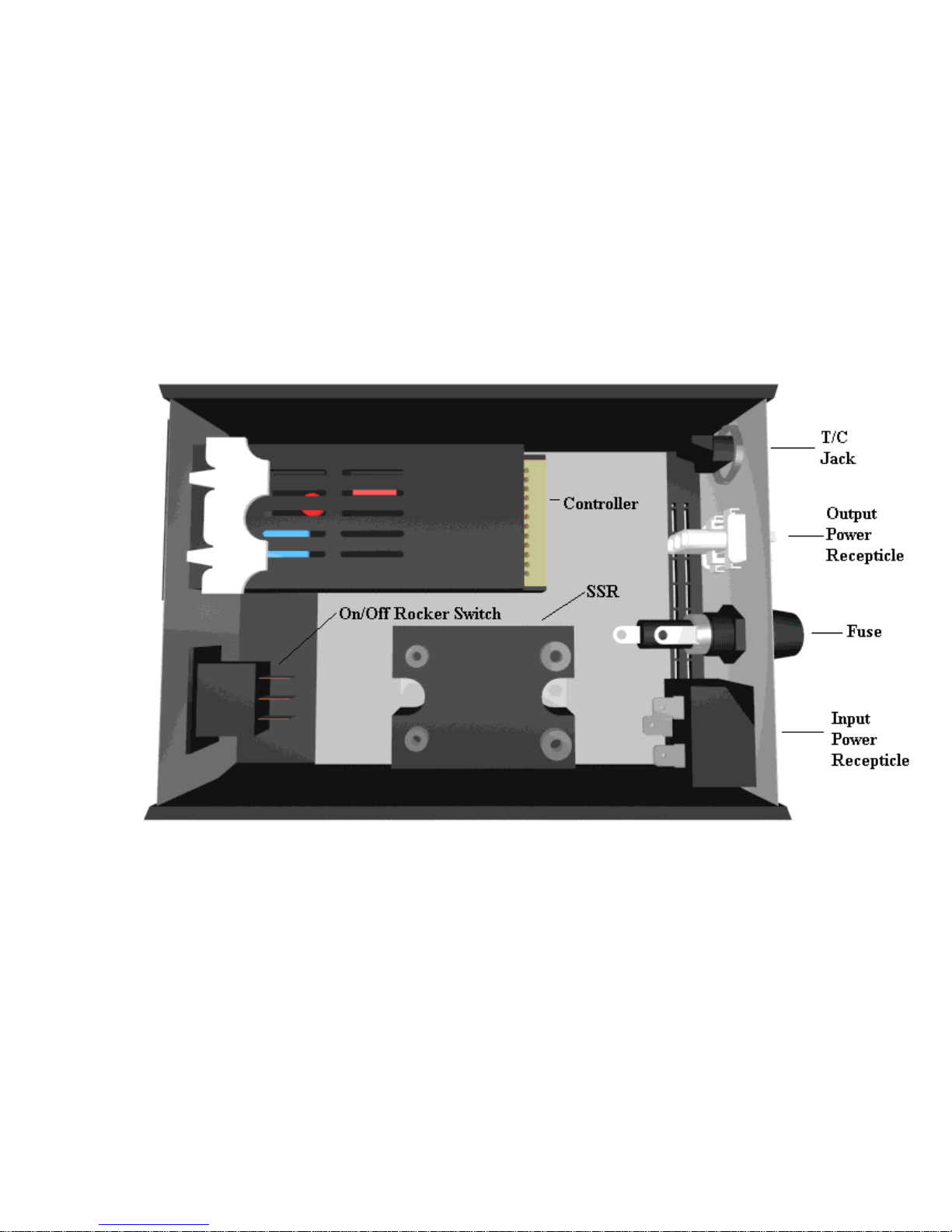
Figure 3: Layout of Internal Components
6
Controller Key Functions
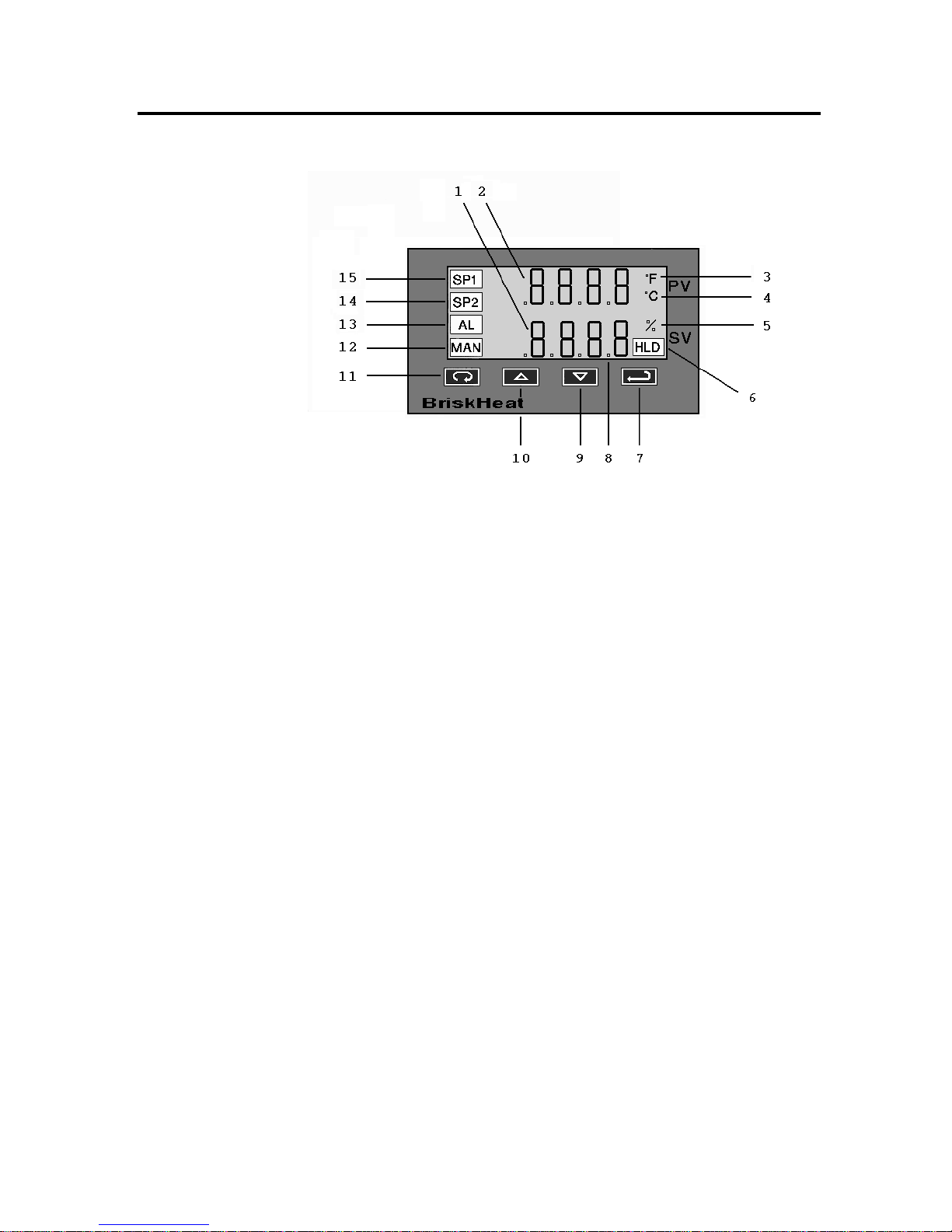
Figure 4: Dual Display Controller
1. Setpoint Display: Displays the SV (setpoint value). The SV is
the setpoint entered by the operator.
2. Process Display: Displays the PV (process value). The PV is
the actual temperature of the system being controlled.
3. oF Lamp: Lit when the temperatures displayed are in degrees
Fahrenheit.
4. oC Lamp: Lit when the temperatures displayed are in degrees
Celsius.
5. Percent Lamp: Lit when controller is programmed to display
percentage of output power.
6. Hold Lamp: Lit when Ramp/Soak program functions are
suspended.
7. ENTER: Pressing ENTER stores the value or the item changes.
If not pressed, the previously stored value or item will be
retained. The display will flash once when ENTER is pressed.
8. This decimal point flashes when SELF-TUNE is operating.
9. DOWN ARROW: Decrements a value, changes a menu item,
or selects the item to OFF. The minimum value obtainable is 1999 regardless of the decimal point placement.
7

10. UP ARROW: Increments a value, changes a menu item, or
selects the item to ON. Maximum value attainable is 9999
regardless of the decimal point placement.
11. INDEX: Pressing the INDEX key advances the display to the
next menu item. Also used in conjunction with other keys.
12. Manual Indicator: Lit when output of control is being
manually adjusted.
13. Alarm Indicator: Lit when a fault condition exists.
14. Setpoint 2 Lamp: Lit when the SV displayed relates to setpoint
2.
15. Setpoint 1 Lamp: Lit when the SV displayed relates to setpoint
1.
Key Combinations:
• UP ARROW & ENTER: Pressing these keys simultaneously
brings up the Secondary Menu starting at the alarm, tune, or
cycle item (depending on the programming). Pressing these
keys for 5 seconds will bring up the Secure Menu.
• INDEX & DOWN ARROW: Pressing these keys
simultaneously will allow backing up one menu item, or if at the
first menu item, they will cause the display to return to the
Primary Menu. If an alarm condition has occurred, then these
keys may be used to reset the alarm. To reset an alarm press and
hold both keys for three seconds.
• INDEX & ENTER: Pressing these keys simultaneously and
holding them for 5 seconds allows recovery from the various
error messages.
Programming
Instructions
pertains to a parameter of the controller.
The controller’s programming is divided up into three menus:
Primary Menu
Within each menu are menu items. Each of the menu item
!
Secondary Menu
!
Secure Menu
8

To enter and move from menu item to menu item within the
Primary Menu:
• Press the UP ARROW and ENTER keys.
• Press INDEX to advance through the menu items.
• Simultaneously, press INDEX and DOWN ARROW keys to
back up one menu item.
• Press UP ARROW or DOWN ARROW to change the value in
the display.
• Press ENTER to retain the value.
To enter and move from menu item to menu item within the
Secondary Menu:
• Press the UP ARROW and ENTER keys.
• Press INDEX to advance through the menu items.
• Simultaneously, press INDEX and DOWN ARROW keys to
back up one menu item.
• Press UP ARROW or DOWN ARROW to change the value in
the display.
• Press ENTER to retain the value.
To enter and move from menu item to menu item within the Secure
Menu:
• Hold the UP ARROW and ENTER simultaneously for five
seconds to enter the secure menu.
• Press INDEX to advance through the menu items.
• Simultaneously, press INDEX and DOWN ARROW keys to
back up one menu item.
• Press UP ARROW or DOWN ARROW to change the value in
the display.
• Press ENTER to retain the value.
Security
locks out programming access to specific menus. To access the
locked out menus the security level must be changed. To
change the security level, the correct password must be entered
into the SECr menu item.
The security code is located in the Secure Menu. The code
1. Hold the UP ARROW and ENTER simultaneously for five
seconds to enter the secure menu.
9
 Loading...