


Page 1
bhibhi
bhibhi
bhi
NEDSP1061-PCB
Noise Eliminating Modules
Installation and
Operating Manual
1061-108D
Issue C
DSP Noise Cancelling Products
Page 24
bhi ltd
PO Box 318
Burgess Hill
West Sussex
RH15 9NR
tel: +44 (0)845 217 9926
fax: +44 (0)845 217 9936
sales@bhi-ltd.com
www.bhi-ltd.com
bhibhi
bhibhi
bhi
DSP Noise Cancelling Product s

Page 2
Important Information
Copyright
This publication, including all photographs and
illustrations is protected under international
copyright laws, with all rights reserved. Neither
this manual, nor any of the material within, may
be copied or reproduced without the written
consent of bhi Ltd.
Disclaimer
The information in this document is subject to
change without notice. bhi Ltd. makes no
representations or warranties with respect to the
contents hereof and specifically disclaims any
implied warranties of merchantability or fitness for
any particular purpose. Furthermore, bhi Ltd.
reserves the right to revise this publication and to
make changes from time to time in the content
hereof without obligation of bhi Ltd. to notify any
person of such revision or changes.
Page 23
Notes:

Page 3
Contents
1. Introduction
1.1 NEDSP1061 features 4
1.2 Limitations 4
1.3 Module connection and mounting 5
1.4 DSP noise cancellation 6
2. Module description
2.1 Block diagram 7
2.2 Module layout 8
2.3 Pin functions 9
2.4 Controls 10
2.5 Electrical characteristics 10
3. Installation 11
4. Functions
4.1 Noise reduction levels 13
4.2 Pre-setting different DSP levels 13
4.3 Remote setting of DSP level 14
4.4 Noise cancellation on/off 15
5. Application notes
5.1 Noise cancellation indication 16
5.2 Remote adjustment of level 17
5.3 Driving a low impedance load 19
5.4 Audio bypass 19
Index 20
Page 22
Notes:

Page 4
1. Introduction
The NEDSP1061 is a modular solution to noise reduction.
It incorporates DSP technology to provide up to 35dB of
noise cancellation.
1.1 NEDSP1061 module features:
Fully adaptive to changing noise environments
Input and output level controls
Virtually no distortion to speech signal
Up to 35dB of noise cancellation
8 levels of noise reduction
Noise cancellation can be preset or remotely set
during operation
5 – 15V supply range
4.6dB on board gain
Wide range of connection possibilities
Mounting holes
1.2 Limitations.
This module is designed to pass speech. Other signals
such as data, music and morse (CW) will to some degree
pass through, but the integrity of these signals
cannot be guaranteed.
This module is designed to be placed in a low level audio
path only. The module will not drive a loudspeaker or
other high power load.
Page 21
Notes:

Page 5
Plug in Vertically
Plug in Horizontally
Horizontal connector
Figure 1. Connection options
1.3 Module connection and mounting
Connections to the module are made by a row of 10
pads at the right hand side of the PCB. These pads are
on a 2.54mm (0.1”) pitch, which allows the use of
standard pin headers, PCB connectors and direct wiring.
Vertical mounting.
Use a 10 way 0.1” pitch right
angled pin header in the PCB
(J2). The module can then plug
into a suitable mating connector,
or be soldered directly to the
target system.
Horizontal mounting.
Use a 10 way 0.1” pitch straight
pin header in PCB (J2). Mount a
4 way header in the PCB (J1).
Do not connect these pins to the
circuit, use them purely for
mechanical fixing.
Other options.
Use a right angled pin header to
mate with a 10 way wired
connector.
Wire the PCB directly and mount
using the four fixing holes.
Page 20
Index
A
Application Notes 16
Audio bypass 19
Audio input. 9
Audio out 9
B
Buffered output stage 19
C
Copyright 2
D
Disclaimer 2
Driving a low impedance load 19
DSP filter level set 9
E
Electrical characeristics 10
I
Important Information 2
inhibit noise cancellation, 15
M
microcontroller. 18
N
Noise Cancellation On/Off 15
Noise cancellation on/off 9
Noise cancellation On/Off indication 16
Noise reduction levels 13
noisy audio 11
R
Remote adjustment of noise cancellation level. 17
Remote setting of DSP filter level 14
Remote setting of the DSP 14
S
safety critical 19
Setting different filter levels 13
Supply voltage 9
T
tricolour LED 16

Page 6
1.4 DSP Noise cancellation.
The bhi DSP processes the incoming signal and then
differentiates the speech from the noise. The unwanted
noise and interference is then attenuated to leave only
the speech.
The following diagrams are taken from actual audio
signals and illustrate how the signal is being processed.
Figure 1. Noise cancellation.
Original signal.
Speech with a lot of
background noise
Processed speech.
Speech with reduced
noise
Speech Noise
Reduced noise
Page 19
NEDSP 1061
Audio out
10
0V
7
-
+
+V
R1
10K
R2
10K
Buffered
Audio out
Bias to 1/2
off supply voltage
or use dual polarity
power supply
Figure 12. Buffered output stage.
5.3 Driving a low impedance load.
If the target system loads the output of the DSP module
it may necessary to buffer the output. This can be
achieved with a single op amp.
10
7
9
NEDSP 1061
Audio out
Audio In
0V
+V
5
Audio out
Audio in
Relay
Contacts
Power
off/bypass
switch
Vin
Relay
Coil
Protection
Diode
Figure 13. Audio bypass.
5.4 Audio Bypass.
In safety critical applications a bypass should be included
to maintain communications in the unlikely event of the
NEDSP1061 or the power failing. The following circuit
uses a relay to route the audio signal. In the even of
power failure to the module the relay will de-energise
and connect the input to output. Also shown is a switch
to bypass the module manually.

Page 7
2. Module description
Figure 2. NEDSP1061 block diagram
Output level
set
Input level
set
Analogue to
Digital conversion
Digital to analogue
conversion
BCD
DSP level select
Xtal
Clock generator
On Board
Jumpers
DSP core
10
9
1
2
3
8
7
3.3V
3.3V regulator
Polarity
protection
PCB
Connections
Internal
pull up
resistors
N0
N1
Vin
0V
N2
Noff
In
Out
5
2.1 Block diagram.
The NESDP1061 module has the facility to be preset, or
adjusted during operation. Digital inputs control the
functions. These incorporate internal pull up resistors,
so they can be left floating when not in use.
The audio signals into and out of the module are capacitor
coupled.
The on board voltage regulator allows the module to be
used with a wide range of input voltages, but to keep the
power dissipation (and heat) down it is advisable to use
as low as possible supply voltage. The power supply
input is reverse polarity protected.
Page 18
NEDSP 1061
N0
1
N1
2
N2
3
0V
7
micro controller
Figure 10. Control using a microcontroller
The module can be controlled with a microcontroller. As
the DSP employs internal pull ups, it is not necessary to
drive the microcontroller port pins high, they can be
placed in a high impedance state.
NEDSP 1061
N0
1
N1
2
N2
3
micro controller
a
b
c
d
e
f
g
display
BCD to
7 segment
decoder
CD4511
A
B
C
0V
Seven segment LED
display showing
DSP filter level
(note: displays 0 - 7)
Keyboard
Noff
8
Figure 11. Control using a microcontroller with display
and keyboard.
The following example employs a 7 segment display and
keyboard. Noise on/off is also controlled by the
microcontroller. In the diagram 3 buttons are used, up
level, down level and DSP on/off.

Page 8
++
1
2
3
4
5
6
7
8
9
10
JP3
JP1
JP2
Connections
Do not
Connect
these
pins
Mounting
holes
(4 off)
Input
level
Output
level
Noise cancellation
level jumpers
Top
Figure 3. NEDSP1061 connections and controls
2.2 Module Layout.
The following diagram shows the layout of the
NEDSP1061 module.
.oNniP emaN noitpircseD
1
0NtibnoitallecnacesionbslDCB
2
1NtibnoitallecnacesionDCB
3
2NBSMnoitallecnacesionDCB
4
C/Ntcennocto
noD
5
niVegatlovylppuS
6
C/NtcennoctonoD
7
V0noitcennocV0
8
ffoNnipffo/nonoitallecnacesioN
9
nItupnioiduA
01
tuOtuptuoo
iduA
Table 1. NEDSP1061 connection functions
Page 17
5.2 Remote adjustment of noise cancellation
level.
NEDSP 1061
N0
1
N1
2
N2
3
0V
7
0V
C
124
BCD
Complement
switch
This page illustrates various options for altering the DSP
level remotely, during operation.
Figure 8. Basic setting using a BCD switch
NEDSP 1061
N0
1
N1
2
N2
3
0V
7
124
0V
Note:
Inputs
will be inverted
N0
N1
N2
Figure 9. Basic setting using transistors
The transistors allow interfacing
with higher voltages to control the
DSP level. These could be
replaced by opto couplers for
greater isolation.

Page 9
2.3 Pin functions.
The basic operation of the NEDSP pins are described
below. More detailed descriptions can be found later in
this manual.
Pins 1-3 DSP filter level set.
These pins allow remote setting of the noise cancellation
level. If these pins are used, then remove the preset
jumpers JP1 - JP3 from the PCB.
Pin 5. Supply voltage.
Supply voltage 5-15VDC
Pin 7 0V
0V pin.
Pin 8 Noise cancellation on/off
Connecting this pin to 0V inhibits the noise cancellation.
Leave this pin floating to enable noise cancellation.
Pin 9 Audio input.
Audio signal to be processed.
Pin 10 Audio out
DSP processed signal out from the module.
For optimum performance, keep all leads as short as
possible. Use screened leads for the audio signal.
Page 16
5. Application Notes.
5.1 Noise cancellation On/Off indication.
Figure 7. Red/Green LED indication of noise cancellation.
In the above example a tricolour LED (or separate Red
and Green LEDs) are used to give a visual indication of
the noise cancellation mode. The green LED will
illuminate when the noise cancellation is on, and the red
when off.
NEDSP 1061
0V
7
Noff
8
+V
0V
Red Green
R1 R2
Noise
cancellation
Off
DPDT
switch

Page 10
2.4 Controls.
The audio level control potentiometers P1 (Audio out),
and P2 (Audio in) provide adjustment to the audio levels
entering and leaving the module.
P1 is factory set near to maximum.
T o set the input level correctly , adjust P2 until the
overload led D1 (next to P2) illuminates, then back off
the potentiometer approximately a 1/4 of a turn.
Turning the potentiometers anti clock wise will increase
the levels.
scitsiretcarahCeugolanA
retemaraP noitpircseD niM pyT xaM stinU
V
ni
egatlovylppuS5951V
I
ni
tnerrucylppuS5405Am
nIlangistupnioiduA05003smrV
tuO
langistuptuooiduA
)xamtupnisX7.1(
036smrV
scitsiretcarahClatigiD
retemaraP noitpircseD niM pyT xaM stinU
V
hgiHni
ttimhcS(egatlovtupnIleveLhgiH
)reggirt
3.3V
V
woLni
ttimcS(egatlovtupnIlevelwoL
)reggirt
8.0V
I
hgiHnI
hgihtupni-tnerrucegakaeltupnI010306Au
I
woLI
woltupni-tnerrucegakaeltupnI01-03-06-Au
Table 2. NEDSP1061 Electrical characeristics
2.5 Electrical characteristics.
Page 15
leveL 2N 1N 0N
1V0V0V0
2V0V0V3.3
3V0V3.3V0
4V0V3.3V3.3
5V3.3V0V0
6V3.3V0V3.3
7V3.3V3.3V0
8V3.3V3.3V3.3
Note:
The DSP has internal pull ups on its inputs, so any cell
in the table containing 3.3V may be left open circuit.
When processing signals with high levels of noise and
high levels of noise cancellation, the signal may sound
slightly strange. This is quite normal with this type of
signal.
4.4 Noise Cancellation On/Off
The module has the provision for remotely enabling and
disabling the noise reduction, while in operation. The
default setting for the module is noise cancellation on.
This may be switched by the use of the noise cancellation
on/off pin (PCB pin 8).
To inhibit noise cancellation, connect this pin to 0V.
T o enable noise cancellation leave the pin unconnected.
Table 5. Remote DSP level setting.
Output impedance: Nominally 10k Ohms
Input impedance: 7.5k Ohms typical

Page 11
3. Installation
Figure 4. Basic connection diagram
The NEDSP1061 module is inserted into the path of noisy
audio. Using the input and output level controls allows
the unit to appear transparent to the audio signal.
NEDSP1061 Power ampPre amp
Audio in Audio out
NEDSP1061 Power amp
Audio outMicrophone
Microphone
Pre amp
Audio in Audio out
Pre amp Power amp
NEDSP1061
Place NEDSP1061 module
in place of the coupling
capacitor
Figure 5. NEDSP1061 Audio path
Page 14
leveL 3PJ 2PJ 1PJ
1nOnOnO
2nOnOffO
3nOffOnO
4nOffOffO
5ffOnOnO
6ffOnOffO
7ffOffOnO
8ffOffOffO
4.3 Remote setting of DSP filter level.
Remote setting of the DSP level can be achieved through
the PCB connections. This allows the DSP filter level to
be changed during operation. If remote DSP setting is
used, remove the jumpers from the module.
These connections are connected directly to the DSP.
The logic levels of the DSP are 3.3V, do not apply a
voltage greater than this.
To set the DSP level remotely connect the pins N0, N1
and N2 (PCB pins 1,2, and 3) as shown on the following
page.
Table 4. Preset DSP levels using on board jumpers.
Page 12
The NEDSP1061 requires a signal of 50mV rms or
greater for optimum performance. Signals lower than this
may be used but the noise cancellation performance will
degrade, as the signal levels drops. If the unit is used
with low level microphones, the signal will need amplifying
before applying it to the NEDSP1061. The output level
can then be used to attenuate the signal back down to
the original signal level.
Figure 6. Signal levels.
Due to the adaptive nature of the noise cancellation a
small delay may be heard when the audio signal
changes. For optimum performance provide the module
with a constant signal, for example if the unit is installed
into a system employing a push to talk button - insert
the NEDSP1061 in to the audio path before the button.
Audio in Audio out
Input signal level Original signal level
NEDSP1061
635mV rms Max
Output level
Post processingPre processing
Gain = 1.7
>50mV rms
Page 13
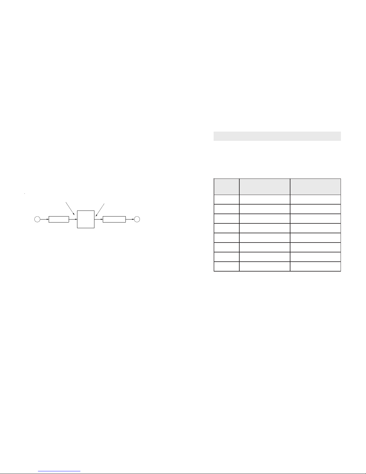
4. Functions
4.1 Noise reduction levels.
8 levels of noise reduction are available. The amount of
noise and tone reduction is shown in the table below.
leveL noitcudeRenoT
esioNetihW
noitcudeR
1Bd4Bd9
2Bd5Bd11
3Bd6Bd31
4Bd8Bd51
5Bd61Bd71
6Bd12Bd02
7Bd52Bd42
8Bd56Bd53
4.2 Setting different filter levels.
The levels are set by applying a BCD code to three
jumpers on the module. See the table on the following
page for more information. The positions of the jumpers
are shown in section 2.1 module layout.
Table 3. Tone and noise reduction levels.
 Loading...