

BH Fitness R350 Service Manual
R350
Instrucciones de montaje y utilización
Instructions for assembly and use
Instructions de montage et utilisation
Montage und Gebrauchsanleitung
Instruções de montagem e utilização
Istruzioni di montaggio e uso
Montage-en gebruiksinstrukties

Fig.0
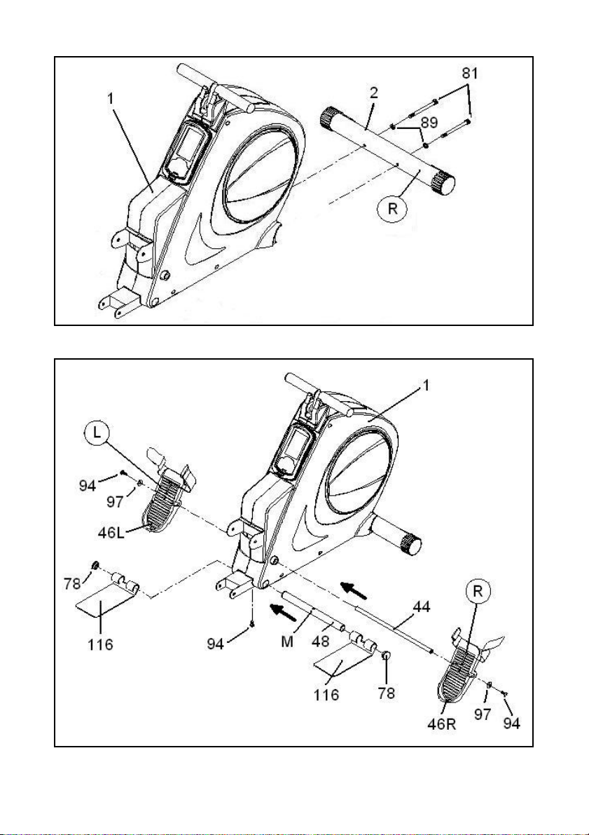
Fig.1
Fig.2

Fig.3
Fig.4 Fig.5

Fig.6 Fig.7
Fig.8

Fig.9
Fig.10

Fig.11
Fig.12

Español
INSTRUCCIONES DE
SEGURIDAD.-
Antes de comenzar cualquier
programa de ejercicio, consulte a su
médico. Se recomienda la realización
de un examen físico completo.
Trabaje en el nivel de ejercicio
recomendado, no llegue al agotamiento.
Si siente dolor o molestias de cualquier
tipo, pare el ejercicio inmediatamente y
acuda a su médico.
Utilice el aparato sobre una superficie
sólida y nivelada, con algún tipo de
protección para el suelo o alfombra.
INDICACIONES GENERALES.-
Lea atentamente las instrucciones de
este manual. Este le da indicaciones
importantes sobre el montaje,
seguridad y uso de la máquina.
1 Este aparato ha sido probado y
cumple con la norma EN957 bajo la
clase H.C. adecuado sólo para uso
doméstico. Peso máximo del usuario
136kg.
2 Mantenga las manos alejadas de
cualquiera de las partes móviles de la
unidad.
3 Sólo puede utilizar el aparato una
persona cada vez.
4 Si sufre mareos, nauseas, dolor en
el pecho o cualquier otro síntoma
durante la utilización de este aparato,
PARE el ejercicio. ACUDA A UN
MÉDICO INMEDIATAMENTE.
5 Utilice el aparato sobre una
superficie sólida y a nivel. NO utilice la
bicicleta cerca del agua o al aire libre.
6 Los padres y otras personas
responsables de los niños deben de
tener en cuenta la naturaleza curiosa
de estos y que puede llevarles a
situaciones y conductas que pueden
resultar peligrosas.
Esta unidad no ha de utilizarse en
ningún caso como juguete.
7 Su unidad sólo puede ser usada por
una persona al mismo tiempo.
8 Utilice prendas de vestir y calzado
adecuado. Átese los cordones
correctamente.
9 Utilice este aparato sólo para los
fines descritos en este manual. NO
utilice accesorios no recomendados
por el fabricante.
10 No coloque objetos cortantes
alrededor de la máquina.
11 Las personas discapacitadas no
deberán utilizar la máquina sin la
asistencia de una persona cualificada
o un médico.
12 Antes de utilizar este aparato,
realice un calentamiento con
ejercicios de estiramiento.
INSTRUCCIONES PARA EL
EJERCICIO.-
La fase de calentamiento
Esta fase acelera la circulación
sanguínea en el cuerpo y pone a tono
los músculos para el ejercicio.
También reduce el riesgo de
calambres y lesiones musculares. Es
aconsejable realizar algunos ejercicios
de estiramiento, según se muestra
más adelante.
8

Realice cada estiramiento aproximadamente durante 30 segundos, no fuerce
los músculos. Si siente dolor, PARE.
Guarde estas instrucciones.
1. INSTRUCCIONES DE
MONTAJE.-
Saque la unidad de la caja y
compruebe que tiene todas las piezas
Fig.0.
Se recomienda la ayuda de una
segunda persona para la
realización de este montaje.
(1) Cuerpo principal.
(2) Tubo caballete delantero con
ruedas.
(44) Eje de giro apoya pies.
(46L) Apoya pies Izquierdo.
(46R) Apoya pies Derecho.
(47) Cintas de sujeción calapies.
(48) Eje de apoyo apoya pies.
(52) Carril de asiento.
(55) Tapa soporte trasero.
(60) Soporte de sujeción plegado.
(62) Soporte trasero de carril.
(64) Soporte de asiento.
(68) Asiento.
(116) Soportes de pie tiro vertical.
(119) Transformador 6v 1Amp.
TORNILLERIA
(63) Pasador de seguridad.
(78) Tapón embellecedor.
(79) Tapón de tuerca.
(81) Tornillo allen M-8x70.
(89) Arandela de muelle M8.
(94) Tornillo allen M-8x15.
(95) Tornillo allen M-6x15.
(97) Arandela plana M-8.
(109) Tornillo M-8x15.
Llave de allen de 6 mm.
Llave combinada
Llave de tubo mixta con destornillador
estrella.
2 COLOCACION DE LOS
TUBOS CABALLETE.-
Acerque el tubo de caballete delantero
con ruedas (2) al cuerpo central (1),
posicionando las ruedas hacia delante
de la unidad, Fig.1, introduzca los
tornillos (81), coloque las arandelas
planas (89) y ayudándose de la llave
de allen de 6 mm.apriete fuertemente.
3 COLOCACION EJE DE
TOPE APOYAPIES.-
Coja el eje mas corto (48),
introdúzcalo por el agujero inferior de
la estructura (1) Fig.2 y déjelo
centrado con la estructura, y alineado
con el agujero del tornillo (94) Fig.2,
apriete el tornillo (94).
A continuación introduzca por los
extremos del tubo que acaba de
montar los soportes de tiro vertical
(116) y coloque los tapones
embellecedores (78).
4 MONTAJE DE LOS APOYA
PIES.-
En primer lugar introduzca el eje de
mayor longitud (44) en el agujero de la
estructura como muestra en la Fig.2,
dejándolo centrado.
9

Seguido coja el apoya pie izquierdo
(46L) y móntelo en el eje (44) Fig.2, a
continuación realice la misma operación
con el apoya pie derecho (46R).
Coja las arandelas planas (97), y los
tornillos (94) y atornille por cada
extremo del eje ayudándose de la
llave allen 6 mm.
Una vez realizado el montaje de los
apoya pies coja las cintas de sujeción
pies (47) y acóplelas en el apoya pies.
5.- MONTAJE DEL CARRIL
DE ALUMINIO.-
Introduzca el carril de aluminio (52) en
dirección de la flecha, en el cuerpo
central (1) Fig.3.
Coloque el tornillo (103) en dirección de
la flecha y tuerca (105) soltada
anteriormente Fig.3 y apriete. Coloque el
tapón embellecedor de tuerca (79) Fig.3.
Suelte el tornillo (101), junto con la
tuerca (105) de la “U” del cuerpo
central (1). Posicione el soporte de
sujeción de plegado (60) sobre la “U”
y atornille con el tornillo (101) soltado
anteriormente.
Levante el carril de aluminio que acaba
de montar como le indica la Fig.4.
Tire del pomo (59) y levante el soporte
hasta hacer coincidir con los agujeros
de amarre, coloque los tornillos (97) y
apriete fuertemente.
6.-MONTAJE DEL SILLÍN.-
En primer lugar Fig.5 coja el soporte del
sillín (64) y tire hacia fuera del pomo
(67), Fig.E y gírelo hasta enclavarlo.
Posicione el sillín (68) Fig.5 sobre el
soporte del sillín (64) Fig.F y haciendo
coincidir los agujeros atornille con los
tornillos (95).
Suelte el tope de sillín (54) Fig.7 y una
vez montado el sillín introdúzcalo en
el carril de aluminio como le muestra
la Fig.6, cuando llegue a la cremallera
(N) gire el pomo (67) y suelte el pomo
para que se introduzca en los vanos
de la cremallera, quedando bloqueado
el movimiento del sillín sobre el carril
de aluminio.
Coloque el tornillo de tope de sillín
(54) soltado anteriormente e
introduzca el tapón embellecedor (55)
como le muestra la Fig.7.
7.-MONTAJE DEL SOPORTE
TRASERO.-
Posicione el soporte (60) en la parte
superior del carril Fig.6.
Introduzca el tornillo (102) con la
tuerca (105) Fig.6 y apriete
fuertemente.
Coloque el tapón embellecedor de
tuerca (79) Fig.6.
8.- PASADOR DE
SEGURIDAD.-
Coloque el pasador de seguridad (63)
en el soporte como le indica en la
Fig.7.
IMPORTANTE: Este pasador de
seguridad (63) es muy importante que
este colocado en su alojamiento de
bloqueo, tanto cuando esta la
máquina plegada, como cuando la
máquina esta lista para la realización
de los ejercicios.
9.- NIVELACIÓN.-
ATENCIÓN: Es muy importante el
que la máquina este bien nivelada
antes de realizar cualquier ejercicio
sobre la maquina.
Saque el pasador de seguridad (63) y
gire hacia arriba el soporte trasero
(62) hasta hacer coincidir los
agujeros, introduzca el pasador de
seguridad (63).
10

A continuación sujete con una mano
el carril de aluminio y con la otra tire
del pomo (59) Fig.7 y baje el carril con
precaución hasta el suelo Fig.8.
Compruebe que al bajar el carril se ha
oído un “CLIP” de enclavamiento del
pomo (59).
Si al bajar el carril de aluminio no se
ha oído el “CLIP” de enclavamiento,
saque hacia el suelo el tope de
regulación (43) situado en la parte
inferior del cuerpo central (1), hasta
que se enclave el pomo (59) como le
muestra en la Fig.8.
Si al bajar el carril se oye el “CLIP” de
enclavamiento antes de que apoye el
soporte trasero (62) en el suelo Fig.8,
se tiene que meter el tope de
regulación (43), hasta que asienten
perfectamente los tres puntos en el
suelo Fig.8.
Conectar el terminal de recuento de
remadas (74) a la clavija (75) situada
en el soporte de giro del carril de
aluminio como le muestra la Fig.8.
10 PLEGADO DE SU UNIDAD.-
Para el plegado de su unidad, Fig.9,
siga los pasos siguientes:
1.- En primer lugar se tiene que
enclavar el asiento (68) a la cremallera
del carril de aluminio (52) Fig.G.
Retire el pasador de seguridad (63) y
gire el soporte trasero (62) hacia
delante, y coloque el pasador de
seguridad (63).
2.- Tire con una mano del pomo (59)
hacia fuera Fig.G y con la otra mano
levante el carril de deslizamiento del
asiento, hasta que se oiga el “CLIP” de
enclavamiento del pomo (59) Fig.H.
11.-DESPLEGADO DE SU
UNIDAD.-
Para el desplegado de su unidad
Fig.10 siga los pasos siguientes:
1.- Tire con una mano del pomo (59)
hacia fuera Fig.J y con la otra mano
baje el carril de deslizamiento del
asiento, hasta que se oiga el “CLIP”
de enclavamiento del pomo (59)
Fig.H.
2.- Retire el pasador de seguridad
(63) y gire el soporte trasero (62)
hacia atrás, y coloque el pasador de
seguridad (63).
12.- MOVIMIENTO Y
ALMACENADO.-
La unidad está equipada con ruedas
(77) lo que hace más sencillo su
movimiento.
Las ruedas que se encuentran en la
parte delantera de su unidad, le
facilitarán la maniobra de colocar su
unidad en el emplazamiento escogido,
levantando, ligeramente por la parte
delantera y empujando, como muestra
la Fig.11.
Guarde su máquina en un lugar seco
con las menores variaciones de
temperatura posible.
CONEXIÓN A LA RED
Transformador 6V–1Amp.
Introduzca la clavija de enganche (m)
del transformador (119) en el punto de
conexión (n), del cuerpo central (1),
(parte trasera inferior) y conecte el
transformador de corriente a la red de
220 V, Fig.12.
BH SE RESERVA EL DERECHO A
MODIFICAR LAS ESPECIFICACIONES DE SUS PRODUCTOS SIN
PREVIO AVISO.
11

English
SAFETY INSTRUCTIONS.-
Consult your doctor before starting
any exercise program. It is advisable
to undergo a complete physical
examination.
Work at the recommended exercise
level, do not overexert yourself. If you
feel any pain or discomfort, stop
exercising immediately and consult
your doctor.
Use the appliance on a solid, flat
surface, with some type of protection
for the floor or carpet.
GENERAL INSTRUCTIONS.-
Carefully read through the instructions
contained in this manual. It provides
you with important information about
assembly, safety and use of the
machine.
1 This appliance has been tested and
it complies with standard EN957 under
class H.C., suitable for domestic use
only. Maximum user weight 136 kg.
2 Keep your hands well away from
any of the moving parts.
3 It can only be used by one person at
a time.
4 If you experience dizziness, nausea,
chest pains or any other symptom
while using this appliance STOP the
exercise. SEEK MEDICAL
ATTENTION IMMEDIATELY
5 Use the appliance on a level, solid
surface. DO NOT use the bicycle
outdoors or close to water.
6 Parents and/or those responsible for
children should always take their
curious nature into account and how
this can often lead to hazardous
situations and behaviour resulting in
accidents. Under no circumstances
should this appliance be used as a
toy.
7 Your unit can only be used by one
person at a time.
8 Use suitable clothing and footwear.
Make sure all laces/cords are tied
correctly.
9 This appliance must only be used for
the purposes described in this manual.
DO NOT use accessories that are not
recommended by the manufacturer.
10 Do not place sharp objects near
the machine.
11 Disabled people should not use the
machine without the assistance of a
qualified person or a doctor.
12 Do warm up stretching exercises
before using the equipment.
EXERCISE INSTRUCTIONS.-
Warm-up phase
This phase speeds up the body’s
blood circulation and gets the muscles
ready for exercise. It also reduces the
risk of cramp and sprains.
It is advisable to do some stretching
exercises, as shown below.
12
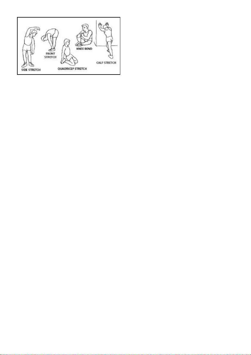
Each stretch should last approximately
30 seconds, do not overexert the
muscles. If you feel pain, STOP.
Keep these instructions safe for
future use.
1. ASSEMBLY INSTRUCTIONS.-
Take the unit out of its box and make
sure that all of the pieces are there Fig.0:
The assistance of a second person
is recommended when assembling
this unit.
(1) Main body.
(2) Front stabiliser bar with wheels.
(44) Footrest rotation shaft.
(46) Right footrest.
(46) Left footrest.
(47) Pedal clip holding straps.
(48) Footrest support spindle.
(52) Seat rail.
(55) Rear support cover.
(60) Folded retaining support
(62) Rear rail support.
(64) Seat support.
(68) Seat
(116) Pull-up foot supports.
(119) Transformer 6v 1Amp.
NUTS & BOLTS.
(63) Lock pin
(78) Screw cap
(79) Nut cap.
(81) Allen screw M-8x70.
(89) Spring washer M8.
(94) Allen screw M-8x15.
(95) Allen screw M-6x15.
(97) Flat washer M8.
(109) Screw M-8x15.
Allen key 6 mm
Combination spanner.
Box spanner with star screw-driver
2. FITTING THE STABILISER
BARS.-
Bring the front stabiliser bar with
wheels (2) to the main body (1)
positioning the wheels at the front of
the unit, Fig.1, insert screws (81), fit
the spring washers (89). Use the 6
mm Allen key to tighten securely.
3. FITTING THE FOOTREST
RETAINER SHAFT.-
Take the shortest shaft (48), insert it in
through the hole at the bottom of the
frame (1) and align it with the hole for
the bolt (94).
Next insert the pull-up supports (116)
into the ends of the tube you have just
finished assembling and fit the screw
caps (78).
4 FITTING THE FOOTRESTS.-
First insert the longest shaft (44) in
through the hole on the frame, as
shown in Fig.2, leaving it centred.
Next, take the left-hand footrest (46)
and fit it onto the shaft (44), Fig.2 and
then do the same with the right-hand
footrest (46).
Take the flat washers (97) and the
Screw (94) and tighten each end of
the shaft using Allen key 6 mm.
Once you have fitted the footrests take
the pedal straps (47) and attach them
to the footrests.
13

5.- FITTING THE ALUMINIUM
RAIL.-
Insert the aluminium rail (52) onto the
main body (1) in the direction of the
arrow, Fig.3.
Fit the bolt (103) in the direction of the
arrow, along with the nut (105)
removed previously, Fig.3 and tighten.
Fit the nut cap (79), Fig.3.
Remove the screw (101) along with
the nut (105) from the “U” piece on the
main body (1). Position the retaining
bar support (60) on the “U” piece and
tighten using screw (101) removed
previously.
Lift the aluminium rail that you have
just fitted as shown in Fig.4.
Pull the knob (59) back and lift the
support so that the bolt holes line up,
fit the bolts (97) and tighten securely.
6.- FITTING THE SADDLE.-
First, Fig.5, take the saddle support
(64) and pull the knob (67) outward,
Fig. E, twisting it so that it locks into
position.
Position the saddle (68), Fig.5, on the
saddle support (64), Fig.F, lining up
the holes and secure using screws
(95).
Remove the saddle stop (54), Fig.7,
and once you have fitted the saddle
insert it into the aluminium rail as
shown in Fig.6, when it reaches the
rack (N) turn the knob (67) and
release it so that it slots into one of the
openings on the rack, preventing the
saddle from moving on the aluminium
rail.
Fit the saddle stop screw (54)
removed previously and fit the end
cap (55), as shown in Fig.7.
7.- FITTING THE REAR
SUPPORT.-
Position the support (60) at the top of
the rail, Fig.6.
Fit the bolt (102) with its nut (105),
Fig.6, and tighten securely.
Fit the nut cap (79), Fig.6.
8.- LOCKING PIN.-
Fit the locking pin (63) onto the
support as shown in Fig.7.
IMPORTANT: Making sure that this
locking pin (63) is fitted into its locking
position, both when the machine is
folded and ready for doing exercises.
9.- LEVELLING.-
ATTENTION: Make sure that the
machine is levelled correctly before
attempting to do any exercise on it.
Pull out the locking pin (63) and swing
the rear support (62) upward so that it
lines up with the holes, reinsert the
locking pin (63).
Next, hold the aluminium rail with one
hand and with the other pull on the
knob (59), Fig.7, carefully lowering the
rail down onto the floor, Fig.8.
Make sure that you have heard the
retaining knob (59) click into place
when you lower the rail.
If you do not hear it click into place
then pull the adjuster (43), located at
the bottom of the main body (1), down
toward the floor so that the knob (59)
locks into position, as shown in Fig.8.
If you hear it click into position before
the rear support (62) is resting on the
floor, Fig.8, push the adjuster (43) in
so that the three points are all level on
the floor, Fig.8.
14

Plug the jack for the stroke counter
(74) into the socket (75) located on the
aluminium rail support, as shown in
Fig.8.
10 FOLDING YOUR UNIT.-
To fold your unit, Fig.9, do the
following:
1.- First lock the seat (68) onto the
rack on the aluminium rail (52), Fig.G.
Pull out the locking pin (63) and swing
the rear support (62) forward and
reinsert the locking pin (63).
2.- Use one hand to pull the knob (59)
back, Fig.G, and use the other hand to
lift the sliding seat rail until you hear
the knob (59) click into position, Fig.H.
11.- UNFOLDING YOUR UNIT.-
To fold your unit, Fig.10, do the
following:
1.- Use one hand to pull the knob (59)
back, Fig.J, and use the other hand to
lower the sliding seat rail until you
hear the knob (59) click into position,
Fig.H.
2.- Pull out the locking pin (63) and
swing the rear support (62) backward
and reinsert the locking pin (63).
12 MOVEMENT & STORAGE.-
The unit is equipped with wheels (77)
to make it easier to move. The wheels
located at the front of your unit make it
easier to move it into a chosen
position, by lifting the rear of the unit
up slightly and pushing it, as shown in
Fig.11. Store your unit in a dry place,
preferably not subject to changes in
temperature.
MAINS CONNECTION.-
Transformer 6 V- 1Amp.
Insert the jack (m) on the transformer
(119) into the connection hole (n) on the
main body (1) (bottom, rear of the
machine) and then plug the transformer
into a 220 V mains supply, Fig.12.
BH RESERVES THE RIGHT TO
MODIFY THE SPECIFICATIONS OF
ITS PRODUCTS WITHOUT PRIOR
NOTICE
15

Français
CONSIGNES DE SÉCURITÉ.-
Avant de commencer tout exercice,
demandez l’avis de votre médecin. Il
est conseillé de passer un examen
médical complet.
Travaillez le niveau d’exercice
recommandé, ne pas aller jusqu’à
l’épuisement. En cas de douleur ou de
malaise, arrêtez immédiatement
l’exercice et consultez votre médecin.
Cet appareil doit être posé sur une
surface solide et bien nivelée avec
une protection ou un tapis au sol.
CONSIGNES GÉNÉRALES.-
Lire cette notice très attentivement.
Elle contient d’importantes
informations sur le montage, la
sécurité et l’utilisation de la machine.
1 Cet appareil a été testé et répond à
la norme EN957 classe H.C. apte pour
l’usage domestique uniquement.
Poids maximum de l’utilisateur: 136kg.
2 Tenir les mains à l’écart de toute
partie mobile de la machine.
3 Cet appareil ne peut être utilisé que
par une personne à la fois.
4 En cas de malaises, nausées,
douleur dans la poitrine ou tout autre
symptôme durant l’utilisation de cet
appareil, ARRÊTEZ l’exercice et
CONSULTEZ UN MÉDECIN
5 Cet appareil doit être utilisé sur une
surface solide et bien nivelée. NE PAS
utiliser le vélo à proximité de l’eau ni
en plein air.
6 Les parents ou personnes à qui des
enfants ont été confi és doivent tenir
compte de leur soif de curiosité qui
peut les conduire à avoir des conduites risquant de se traduire par des
situations dangereuses. Cet appareil
n’est pas un jouet.
7 Cette machine ne peut être utilisée
que par une personne à la fois.
8 L’utilisateur de la machine doit
porter des vêtements et des
chaussures appropriés. Nouez bien
vos lacets de chaussures.
9 Cet appareil ne doit être utilisé qu’aux
fins indiquées dans cette notice. NE
pas utiliser d’accessoires autres que
ceux recommandés par le fabricant.
10 Ne pas poser d’objets coupants
aux abords de la machine.
11 Les personnes handicapées ne
pourront utiliser la machine que si
elles sont accompagnées par une
personne qualifi ée pour ce faire ou
par un médecin.
12 Avant d’utiliser cet appareil,
l’utilisateur doit faire des
échauffements par l’intermédiaire
d’exercices d’étirement.
INSTRUCTIONS POUR
L’EXERCICE.-
Phase d’échauffement.
Cette phase accélère la circulation
sanguine et prépare les muscles pour
l’exercice. Elle réduit également les
risques de crampes et de lésions
16

musculaires. Il est conseillé de faire
quelques exercices d’étirement
comme indiqué ciaprès.
Chaque étirement doit durer environ
30 Secondes. Ne pas forcer les
muscles. En cas de douleur,
ARRÊTEZ l’exercice.
Conservez cette notice.
1. MONTAGE.-
Déballez l’appareil et vérifiez qu’il ne
manque aucune pièce Fig.0.
Pour effectuer ce montage, il est
conseillé de se faire aider par une
autre personne.
(1) Corps principal.
(2) Tube support avant avec
roulettes.
(44) Axe de rotation du repose-pied.
(46) Repose pied gauche.
(46) Repose pied droit.
(47) Bandes fixation cale-pieds.
(48) Axe d’appui des repose-pieds.
(52) Glissière siège.
(55) Cache support arrière.
(60) Support de fixation pliage.
(62) Support arrière glissière.
(64) Support de la selle.
(68) Selle.
(116) Supports pied fond vertical.
(119) Transformateur 6v 1Amp.
VISSERIE
(63) Goujon de sécurité.
(78) Caches embellisseurs.
(79) Cache écrou.
(81) Vis Allen M-8x70.
(89) Rondelle ressort M-8.
(94) Vis Allen M-8x15.
(95) Vis Allen M-6x15.
(97) Rondelle plate M-8.
(109) Vis M-8x15.
Clé Allen de 6 mm.
Clé combinée
Clé à tube mixte avec tournevis étoile.
2. MONTAGE DES TUBES
SUPPORT.-
Approchez le tube du support avant
avec roulettes (2) au corps central (1)
en plaçant les roulettes vers l’avant de
l’unité, Fig.1, introduire les vis (81),
placez les rondelles à ressort (89) et à
l’aide de la clé Allen de 6 mm, vissez
très fort.
3 POSE DE L’AXE DE BUTÉE
DE L’APPUIE-PIED.-
Prendre l’axe le plus court (48),
introduisez-le dans le trou inférieur de
la structure (1) Fig.2, placez-le centré
par rapport à la structure et aligné
avec le trou de la vis (94) Fig.2, serrez
la vis (94).
Ensuite, introduire à travers les
extrémités du tube qui vient d’être
monté, les supports du fond vertical
(116) et posez les caches
embellisseurs (78).
4 MONTAGE DES REPOSEPIEDS.-
Introduire d’abord l’axe le plus long
(44) dans le trou de la structure en
veillant à ce qu’il soit bien centré,
17
 Loading...