

BH Fitness H8705L installation Guide

H8705L-H8705TFT
Instrucciones de montaje y utilización
Instructions for assembly and use
Instructions de montage et utilisation
Montage und gebrauchsanleitung
Instruções de montagem e utilização
Istruzioni di montaggio e uso
Montage-en gebruiksinstrukties
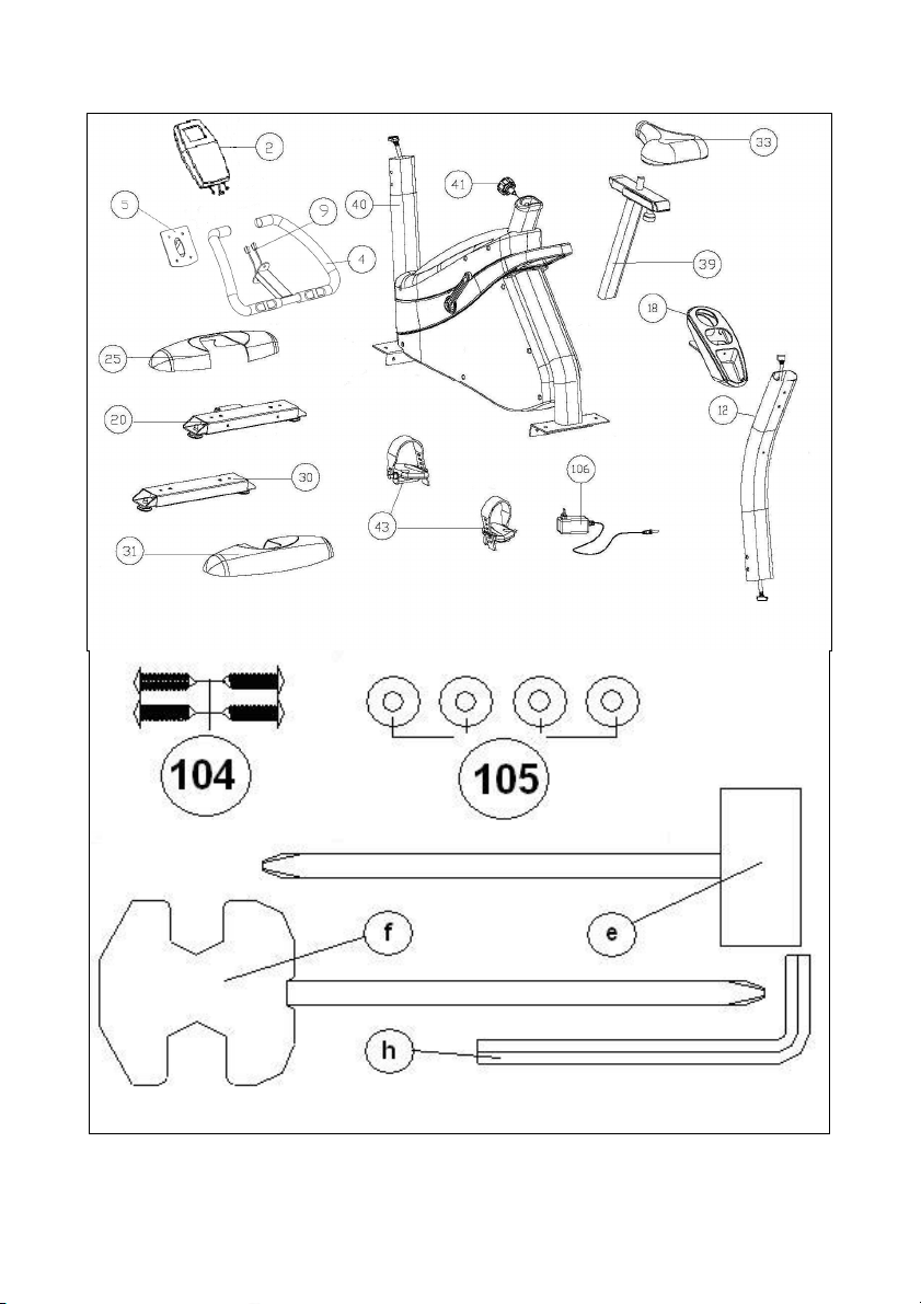
Fig 1

Fig 2
Fig 3

Fig 4
Fig 5

Fig 6 Fig 7
Fig 8

Fig 9 Fig 10
Fig 11

Español
AVISO IMPORTANTE DE
SEGURIDAD
PRECAUCIONES
Esta bicicleta ha sido diseñada y
construida de modo que proporcione
la máxima seguridad. Sin embargo,
deben aplicarse ciertas precauciones
al utilizar aparatos de ejercicio.
Lea el manual en su totalidad antes
de montar y utilizar la bicicleta. Este le
da indicaciones importantes sobre el
montaje, seguridad y uso de la
máquina. Asimismo, cumpla con las
siguientes precauciones de seguridad:
1
Mantenga a los niños alejados de
este aparato en todo momento. NO
los deje desatendidos en la habitación
en la que guarda la bicicleta.
2
Sólo puede utilizar el aparato una
persona cada vez.
3
Si sufre mareos, nauseas, dolor en
el pecho o cualquier otro síntoma
durante la utilización de este aparato,
PARE el ejercicio. ACUDA A UN
MÉDICO INMEDIATAMENTE.
4
Utilice el aparato sobre una
superficie sólida y a nivel. NO utilice la
bicicleta cerca del agua o al aire libre.
5
Mantenga las manos alejadas de
las partes en movimiento.
6
Utilice una indumentaria adecuada
para la realización de ejercicio. No
use prendas holgadas que podrían
engancharse en la bicicleta. Utilice
siempre calzado para correr o para
aerobic cuando utilice la máquina.
Átese los cordones correctamente.
7
Utilice este aparato sólo para los
fines descritos en este manual. NO
use accesorios no recomendados por
el fabricante.
8
No coloque objetos cortantes
alrededor de la máquina.
9
Las personas discapacitadas no
deberán utilizar la máquina sin la
asistencia de una persona cualificada
o un médico.
10
Antes de utilizar este aparato,
realice un calentamiento con
ejercicios de estiramiento.
11
No utilice la bicicleta si no funciona
correctamente.
Precaución: Antes de comenzar a
utilizar la bicicleta, consulte a su
médico. Esta advertencia es
especialmente importante para
personas de edades superiores a
35 años o con problemas de salud.
Guarde estas instrucciones.
INDICACIONES GENERALES
1
Este aparato ha sido probado y
cumple con la norma EN957 bajo la
clase H.B. adecuado para uso semi
profesional. Peso máximo del usuario
120kg. El frenado es independiente de
la velocidad.
2
Los padres y otras personas
responsables de los niños deben de
tener en cuenta la naturaleza curiosa de
estos, que puede llevarles a situaciones
y conductas que pueden resultar
peligrosas. Esta unidad no ha de
utilizarse en ningún caso como juguete.
3
Es responsabilidad del propietario
asegurarse que todos los usuarios de
la máquina estén adecuados e
informados sobre todas las
precauciones necesarias.
7

1. INSTRUCCIONES DE
MONTAJE
Se recomienda la ayuda de una
segunda persona para el montaje.
Saque la unidad de la caja y
compruebe que tiene todas las piezas:
(40) Cuerpo central; (12) tubo
manillar; (20) tubo caballete con
ruedas; (30) tubo caballete con tacos
regulables de altura; (2) monitor con
manillar (4); (25) y (31)
embellecedores; (33) sillín; (43L)
pedal izquierdo; (43R) pedal derecho;
(41) mando regulador altura del sillín;
(106) transformador de corriente.
Bolsa de tornillos que contiene: (104)
tornillo rosca plástico ST4.0x14; (105)
Arandela plana de m4x16; (e) llave
dos bocas hexagonal; (f) llave
combinada de tubo destornillador; (h)
Llave de Allen de 6 mm.
2. COLOCACIÓN DE LOS
TUBOS CABALLETE
Apoye el cuerpo central en un taco del
embalaje, como muestra la figura 2,
(esta posición le facilitará el
montaje).Coja el tubo caballete con
ruedas delantero (20).
Suelte los tornillos (12) con las
arandelas y las tuercas y teniendo en
cuenta de posicionar los dos puntos
rojos (X), alineados, como muestra la
figura 2, introduzca los tornillos (12)
con las arandelas planas y las
tuercas, apriete fuertemente.
A continuación coja el embellecedor
de caballete (25) y apóyelo sobre el
tubo caballete con ruedas (20) que
acaba de montar y sujételo por la
parte inferior con los tornillos de rosca
plástico (104) y las arandelas planas
(105).
Seguido apoye el cuerpo central en un
taco del embalaje, (esta posición le
facilitará el montaje). Coja el tubo
caballete con tacos regulables trasero
(30), y posiciónelo en el caballete
trasero de la máquina, e introduzca
los tornillos (12) con las arandelas
planas y las tuercas, que ha soltado
anteriormente y apriete fuertemente.
A continuación coja el embellecedor
de caballete (25) y apóyelo sobre el
tubo caballete con ruedas (20) que
acaba de montar y sujételo por la
parte inferior con los tornillos de rosca
plástico (104) y las arandelas planas
(105). Figura 3.
3. MONTAJE DE LOS PEDALES
Siga atentamente las instrucciones
de montaje de los pedales, una
colocación incorrecta podría dañar
la rosca del pedal o de la biela.
Las posiciones derecha e izquierda,
habrán de tomarse montado el
usuario en el sillín, en posición de
hacer ejercicio. El pedal derecho
marcado con la letra (43R) se enroscará en sentido de giro de las
agujas del reloj, en la biela derecha
(44R) marcada con la letra (43R).
Apriete fuertemente, figura 4.
El pedal izquierdo, marcado con la
letra (43L), se enroscará en el sentido
contrario a las agujas del reloj, en la
biela izquierda, marcada con la letra
(43L). Apriete fuertemente figura 4.
8

4. MONTAJE TUBO REMO
Conexione los dos terminales (42 y
15) figura 5 que salen del tubo
manillar (12) y del cuerpo central (40).
Introduzca el tubo manillar (12) por el
tubo saliente del cuerpo central (40),
teniendo cuidado de no pillar los cables.
Coloque los tornillos (13) con arandelas
planas como muestra la figura 5, alinee
el tubo manillar y apriete levemente.
5. COLOCACIÓN DEL
PORTABOTELLÍN
Coja el porta botellín (18), introdúzcalo
por la parte superior del tubo manillar
(12) Fig 6.
Seguido suelte los tornillos (17) situados
en el tubo manillar (12), posicione el
porta botellín y atornille con los tornillos
(17) soltados anteriormente.
6. MONTAJE DEL SILLÍN
Para levantar o bajar el tubo de tija
(39), figura 7, afloje primero un poco
el pomo (41) girándolo en sentido
contrario a las agujas del reloj, tire del
pomo hacia atrás y sin soltarlo suba o
baje el tubo tija.
A continuación coja el tubo horizontal
del sillín (18) y monte el sillín (33),
figura 9, apriete las tuercas (Z).
REGULACIÓN VERTICAL.
Para levantar o bajar la tija del sillín,
afloje primero un poco el pomo de la
tija de sillín (41) girándolo en el
sentido contrario a las agujas del reloj.
Tire del pomo y sin soltarlo, mueva la
tija del sillín figura 7. Cuando este a la
altura adecuada, suelte el pomo y el
tubo quedará bloqueado en el
agujero. Apriételo después girando el
pomo (41) en el sentido de las agujas
del reloj.
REGULACIÓN HORIZONTAL.
Para regular el sillín en su posición
horizontal, afloje el pomo del tubo
horizontal del sillín (37), mueva el
sillín con el tubo a su posición
adecuada y apriete fuertemente el
pomo, figura 7.
INCLINACIÓN DEL SILLÍN.
El sillín se puede inclinar hacia
delante o hacia atrás. Afloje la tuerca
(Z) mostrada en la figura 7, colocada
debajo del sillín, mueva el sillín a la
inclinación que desee y a continuación
apriete la tuerca fuertemente.
No ajuste la inclinación del sillín
cuando esté sentado en él.
7 COLOCACION DEL
MANILLAR.-
Sitúe el manillar (4) junto a los
agujeros inferiores del tubo remo (12),
pasando los cables del hand-grip por
el interior del soporte en dirección de
la flecha como le muestra la Fig.8 y
sacándolos por el agujero superior del
remo.
A continuación coja el tornillo (6) la
arandela de muelle (7) y la arandela
plana (8) soltados anteriormente y
atorníllelo por la parte inferior del
manillar (4).
8. COLOCACIÓN DEL MONITOR
Suelte los tornillos (3) Fig. 8 de la
parte trasera del monitor.
Seguido coloque el monitor en dirección
de la flecha sobre la chapa (5) Fig.8,
introduciendo los cables en el interior
del tubo remo y teniendo cuidado de no
pillar los cables. Coloque los tornillos (3)
soltados anteriormente.
9

Conexione los dos terminales que
salen del tubo manillar (4) y del monitor
(2), figura 8.
Introduzca el monitor (2) en el tubo
manillar (12), como indica la figura 8
teniendo cuidado de no pillar los
cables. Coloque los tornillos (6) con
las arandelas planas, y comprobando
que esta bien alineado el manillar y
apriete fuertemente, todos los tornillos
del tubo manillar, también los tornillos
de la parte inferior que en el punto 4
se han dejado apretados levemente.
NIVELACIÓN.
Una vez colocada la unidad en su
lugar definitivo, compruebe que el
asentamiento en el suelo y su
nivelación sean correctos.
Esto lo conseguirá roscando más o
menos el pie regulable (U), figura 9.
MOVIMIENTO Y ALMACENAJE
La unidad esta equipada con ruedas
(V) lo que la hace más sencillo su
movimiento. Las dos ruedas que se
encuentran en la parte delantera de
su unidad, le facilitaran la maniobra de
colocar su unidad en el
emplazamiento escogido, como
muestra la figura 10. Guárdela en un
lugar seco con las menores
variaciones de temperatura posible.
CONEXIÓN A LA RED
Introduzca la clavija de enganche (m)
del transformador (106) en el punto de
conexión (k), del cuerpo central (40),
(parte trasera inferior) y conecte el
transformador de corriente a la red de
220 V, figura 11.
Para cualquier consulta, no dude en
ponerse en contacto con el
(S.A.T).Servicio de Asistencia
Técnica, llamando al teléfono de
atención al cliente (ver página final del
presente manual).
BH SE RESERVA EL DERECHO A
MODIFICAR LAS ESPECIFICACIONES
DE SUS PRODUCTOS SIN PREVIO
AVISO
10

English
IMPORTANT SAFETY ADVICE
PRECAUTIONS
This bicycle has been designed and
constructed to provide maximum
safety. Nevertheless, certain
precautions should be taken when
using exercise equipment.
Read the whole manual before
assembling and using the bicycle. It
provides you with important
information about assembly, safety
and use of the machine.
The following safety precautions
should also be observed:
1
Keep children away from this
equipment at all times. DO NOT leave
them unsupervised in the room where
this bicycle is kept.
2
It can only be used by one person at
a time.
3
If you experience dizziness, nausea,
chest pains or any other symptom
while using this appliance STOP the
exercise. SEEK MEDICAL
ATTENTION IMMEDIATELY
4
Use the appliance on a level, solid
surface. DO NOT use the bicycle
outdoors or close to water.
5
Keep your hands well away from
any of the moving parts.
6
Wear clothing suitable for doing
exercise. Do not use baggy clothing
that might get caught up in the bicycle.
Always wear running shoes or trainers
when using the machine. Make sure
all laces/cords are tied correctly
7
This appliance must only be used
for the purposes described in this
manual. DO NOT use accessories that
are not recommended by the
manufacturer.
8
Do not place sharp objects near the
machine.
9
Disabled people should not use the
machine without the assistance of a
qualified person or a doctor.
10
Do warm up stretching exercises
before using the equipment.
11
Do not use the bicycle if it is not
working correctly.
Caution: Consult your doctor
before beginning to use the bicycle.
This advice is especially important
for those over 35 or suffering from
health problems.
Keep these instructions safe for
future use.
GENERAL INSTRUCTIONS
1
This appliance has been tested and
it complies with standard EN957 under
class H.B., suitable for semiprofessional use User maximum
weight 120kg. Braking is independent
of speed.
2
Parents and/or those responsible for
children should always take their
curious nature into account and how
this can often lead to hazardous
situations and behaviour resulting in
accidents. Under no circumstances
should this appliance be used as a
toy.
3
The owner is responsible for
ensuring that anyone who uses the
machine is duly informed about the
necessary precautions.
11

1. ASSEMBLY INSTRUCTIONS
The assistance of a second person
is advisable for the assembly work.
Take the unit out of its box and make
sure that all of the pieces are there:
(40) Main body; (12) handlebar stem;
(20) Stabiliser bar with wheels; (30)
Stabiliser bar with adjustable blocks;
(2) Monitor with handlebar (4); (25)
and (31) Saddle post covers; (33)
Saddle; (43L) Left pedal; (43R) Right
pedal; (41) Saddle height adjustment
knob; (106) Mains transformer; Bag of
screws containing: (104) Self tapping
screw ST4.0x14; (105) Flatwashers
M4x16; (e) Double ended spanner; (f)
Box spanner with screwdriver; Allen
key 6 mm.
2. FITTING THE STABILISER
BARS
Rest the main body on a wad of
packaging, as shown in figure 2 (this
will help with the assembly work).
Take hold of the front stabiliser bar
fitted with wheels (20).
Remove the bolts (12) and their nuts
and washers. Now line up the two red
dots, as shown in figure 2, and refit
the bolts (12), nuts and washers.
Tighten securely.
Next, take the finish trim piece for
stabiliser (25) and rest it on the
stabiliser bar with wheels (20) that you
have just assembled. Attach the trim
to the bottom using the plastic
threaded screws (104) and flat
washers (105).
Next, rest the main body on a wad of
packaging material (this makes
assembly easier). Take the rear
stabiliser with adjustable feet (30) and
position it on the machine’s rear stand,
insert the bolts (12) with the flat
washers and nuts, tighten securely.
Then take the finish trim piece for
stabiliser (25) and rest it on the
stabiliser bar with wheels (20) that you
have just assembled. Attach the trim
to the bottom using the plastic
threaded screws (104) and flat
washers (105), figure 3.
3. ATTACHING THE PEDALS
The assembly instructions for the
pedals must be followed to the letter,
fitting these incorrectly could damage
the screw thread on the pedal or the
crank. Right and left refer to the
position that the user adopts when
sitting on the saddle to do the
exercises.
The right-hand pedal, marked with the
letter (43R), screws onto the righthand crank (44R), also marked with
an (43R), in a clockwise direction.
Tighten securely, figure 4.
The left-hand pedal, marked with the
letter (43L), screws onto the left-hand
crank, also marked with an (43L), in
an anti-clockwise direction. Tighten
securely figure 4.
4. FITTING THE HANDLEBAR
STEM
Connect the two terminals (15 and 42)
figure 5, coming out of the handlebar
stem (12) and the main body (40).
Insert the handlebar stem (12) onto
the boss on the main body (40) taking
care not to pinch the cables.
Fit the bolts (40) and flat washers, as
shown in figure 5, align the handlebar
stem and hand tighten.
12

5. FITTING THE BOTTLE
HOLDER
Take the bottle holder (18), insert it in
through the top of the handlebar (12),
Fig. 6.
Next, release the screws (17) on the
handlebar (12), position the bottle
holder and secure it by using the
screws (17) removed previously.
6. INSTRUCTIONS FOR
FITTING THE SADDLE
In order to raise or lower the saddle
post (39), figure 7, first loosen off the
control knob (41) on the saddle post a
little by turning it in an anticlockwise
direction.
Pull the control knob back and without
releasing it, move the saddle post up
or down. Next, take the horizontal tube
for the saddle (18) and attach the
saddle (33) to it, figure 7, tighten the
nuts (Z).
VERTICAL ADJUSTMENT.
In order to raise or lower the saddle
post, first loosen off the control knob
(41) on the saddle post a little by
turning it in an anticlockwise direction,
pull the control knob back and without
releasing it, move the saddle post up
or down, figure 7. When it is at the
right height release the knob and it will
lock into a hole on the saddle post.
Tighten it up by turning the control
knob (41) in a clockwise direction.
HORIZONTAL ADJUSTMENT.
To adjust the saddle’s horizontal
position, loosen the control knob (37)
on the saddle’s horizontal bar and
move the saddle, along with the bar,
into the desired position, then tighten
the control knob securely, figure 7.
TILTING THE SADDLE.
The saddle can be tilted backward or
forward. Loosen off nut (Z) shown in
figure 7, located under the saddle, tilt
the saddle into the desired position
and then retighten the nut securely.
Do not adjust the tilt of the saddle
while you are still sitting on it.
7 FITTING THE HANDLEBAR.-
Line the handlebar (4) up with the
lower holes on the main post (12),
passing the hand-grip cables through
the inside of the holder in the direction
indicated by the arrow, as shown in
Fig.8, and pulling them out through the
upper hole of the post. Next, take
screw (6) and flat washer (7) (8),
loosened previously and screw them
onto the bottom of the handlebar (4).
8. FITTING THE MONITOR
Release screws (3), Fig.8, at the back
of the monitor.
Next, slide the front of the monitor
onto the plate (5) in the direction of the
arrow, Fig.8, push the cables down
into the main post making sure not the
pinch any of the cables.
Replace the screws (3) removed
previously.
Bring the monitor (2) to the handlebar
stem (12) figure 8, connect the two
terminals coming out of the handlebar
stem (12) and the monitor (2), figure 8.
Insert the monitor (2) onto the
handlebar stem (12), as shown in
figure 8, making sure not to pinch any
of the cables. Fit the bolts (6) along
with the flat washers, making sure that
the handlebar is aligned correctly,
securely tighten all of the bolts on the
handlebar stem including the bolts at
the base which were left hand tight in
point 4.
13
 Loading...