

BH Fitness H105, H106 User Manual [de]
H105 / H106
Instrucciones de montaje y utilización
Instructions for assembly and use
Instructions de montage et utilisation
Montage- und Gebrauchsanleitung
Instruções de montagem e utilização
Istruzioni di montaggio e uso
Montage-en gebruiksinstrukties

Español
AVISO IMPORTANTE DE
SEGURIDAD
PRECAUCIONES
Esta bicicleta ha sido diseñada y
construida de modo que proporcione la
máxima seguridad. Sin embargo, deben
aplicarse ciertas precauciones al utilizar
aparatos de ejercicio. Lea el manual en
su totalidad antes de montar y utilizar la
bicicleta.
Asimismo, cumpla con las siguientes
precauciones de seguridad:
1 Mantenga a los niños alejados de este
aparato en todo momento. NO los deje
desatendidos en la habitación en la que
guarda la bicicleta.
2 Sólo puede utilizar el aparato una
persona cada vez.
3 Si sufre mareos, nauseas, dolor en el
pecho o cualquier otro síntoma durante
la utilización de este aparato, PARE el
ejercicio. ACUDA A UN MÉDICO
INMEDIATAMENTE.
4 Utilice el aparato sobre una superficie
sólida y a nivel. NO utilice la bicicleta
cerca del agua o al aire libre.
5 Mantenga las manos alejadas de las
partes en movimiento.
6 Utilice una indumentaria adecuada
para la realización de ejercicio. No use
prendas holgadas que podrían
engancharse en la bicicleta. Utilice
siempre calzado para correr o para
aerobic cuando utilice la máquina.
7 Utilice este aparato sólo para los fines
descritos en este manual. NO utilice
accesorios no recomendados por el
fabricante.
8 No coloque objetos cortantes
alrededor de la máquina.
9 Las personas discapacitadas no
deberán utilizar la máquina sin la
asistencia de una persona cualificada o
un médico.
10 Antes de utilizar este aparato, realice
un calentamiento con ejercicios de
estiramiento.
11 No utilice la bicicleta si no funciona
correctamente.
Precaución: Antes de comenzar a
utilizar la bicicleta, consulte a su médico.
Esta advertencia es especialmente
importante para personas de edades
superiores a 35 años o con problemas de
salud. Lea todas las instrucciones antes
de utilizar cualquier aparato de ejercicio.
Guarde estas instrucciones.
INDICACIONES GENERALES
Lea atentamente las instrucciones de
este manual. Este le da indicaciones
importantes sobre el montaje, seguridad
y uso de la máquina.
1 Esta unidad esta diseñada para uso
en casa. El peso de usuario no debe
exceder de 130 Kg.
2 Mantenga las manos alejadas de
cualquiera de las partes móviles de la
unidad.
3 Los padres y otras personas
responsables de los niños deben de
tener en cuenta la naturaleza curiosa de
estos y que puede llevarles a
situaciones y conductas que pueden
resultar peligrosas. Esta unidad no ha
de utilizarse en ningún caso como
juguete.
4 Es responsabilidad del propietario
asegurarse que todos los usuarios de la
máquina estén adecuados e informados
sobre todas las precauciones
necesarias.
5 Su unidad sólo puede ser usada por
una persona al mismo tiempo.
5

6 Utilice prendas de vestir y calzado
adecuado. Átese los cordones
correctamente.
INSTRUCCIONES DE MONTAJE
Saque la unidad de la caja y compruebe
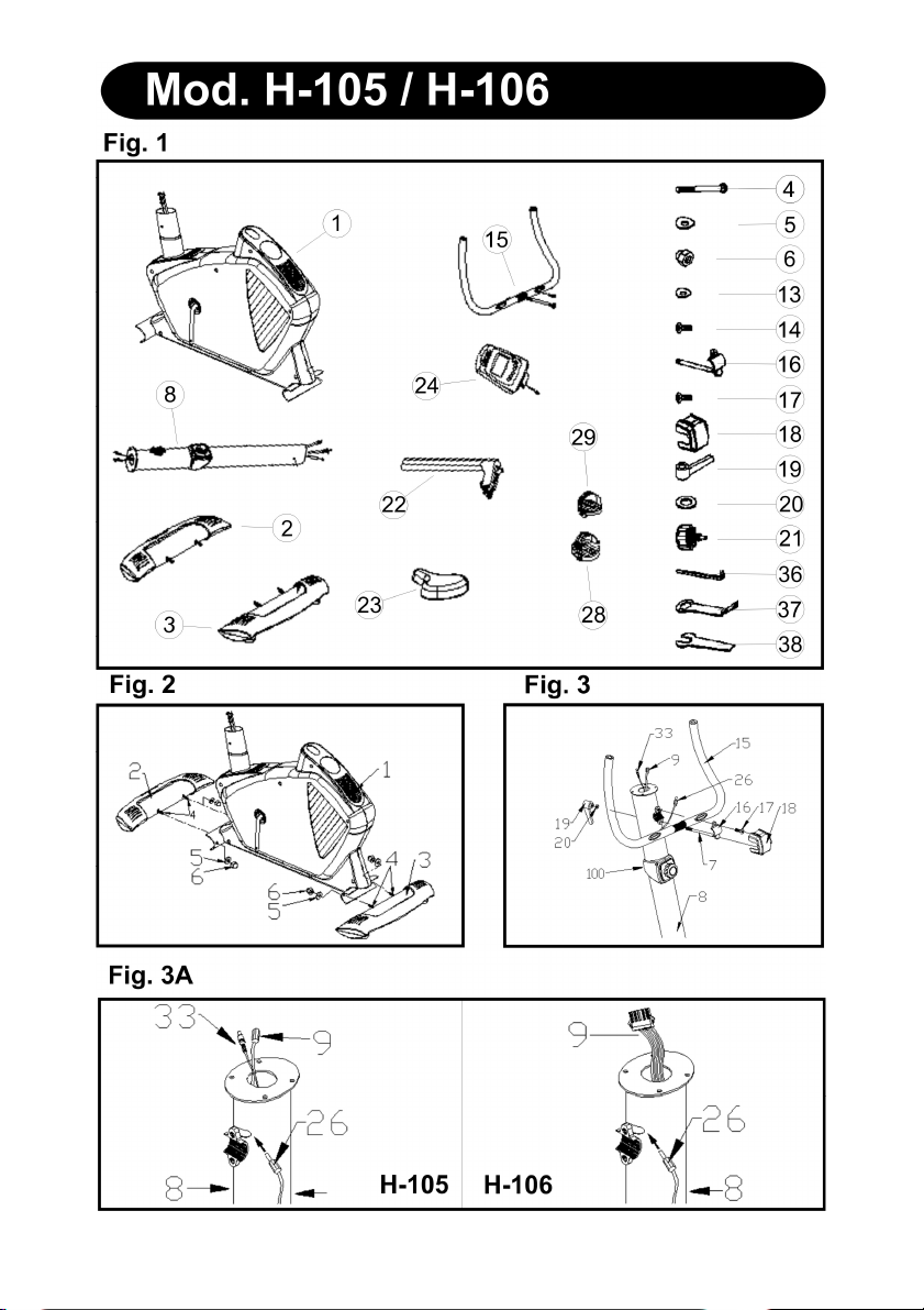
que tiene todas las piezas Fig.1.
1.- (1) Cuerpo principal; (8) Tubo
manillar; (22) Tija de sillín; (23) Sillín;
(15) Manillar; (24) Monitor; (3) Caballete
trasero; (2) Caballete delantero; una
caja con el siguiente contenido: (4)
Tornillo c/ Alomada M-10; (5) Arandela
curvada M-10; (6) Tuerca ciega M-10;
(13) Arandela curvada M-8; (14) Tornillo
c/allen alomado; (16) Brida de fijación
manillar; (17) Tornillo M8; (18) Carcasa
protección brida; (19) Palanca apriete
manillar; (20) Aradela plana M-8; (21)
Pomo apriete tija; (36) Llave Allen; (37)
Llave exagonal de dos bocas; (38) Llave
pedales; (28) Pedal izquierdo (L); (29)
Pedal derecho (R).
2.- Coja el tubo caballete trasero (3) y
posiciónelo en el caballete trasero de la
maquina, como muestra la Fig.2, e
introduzca los tornillos (4), coloque las
arandelas curvadas (5), y las tuercas
ciegas (6), apriete fuertemente.
Coja el tubo caballete delantero con
ruedas (2) y teniendo en cuenta de
posicionar los dos puntos rojos (A),
como muestra la Fig.2, introduzca los
tornillos (4), coloque las arandelas
curvadas (5), y las tuercas ciegas (6) y
apriete fuertemente.
COLOCACIÓN DEL MANILLAR
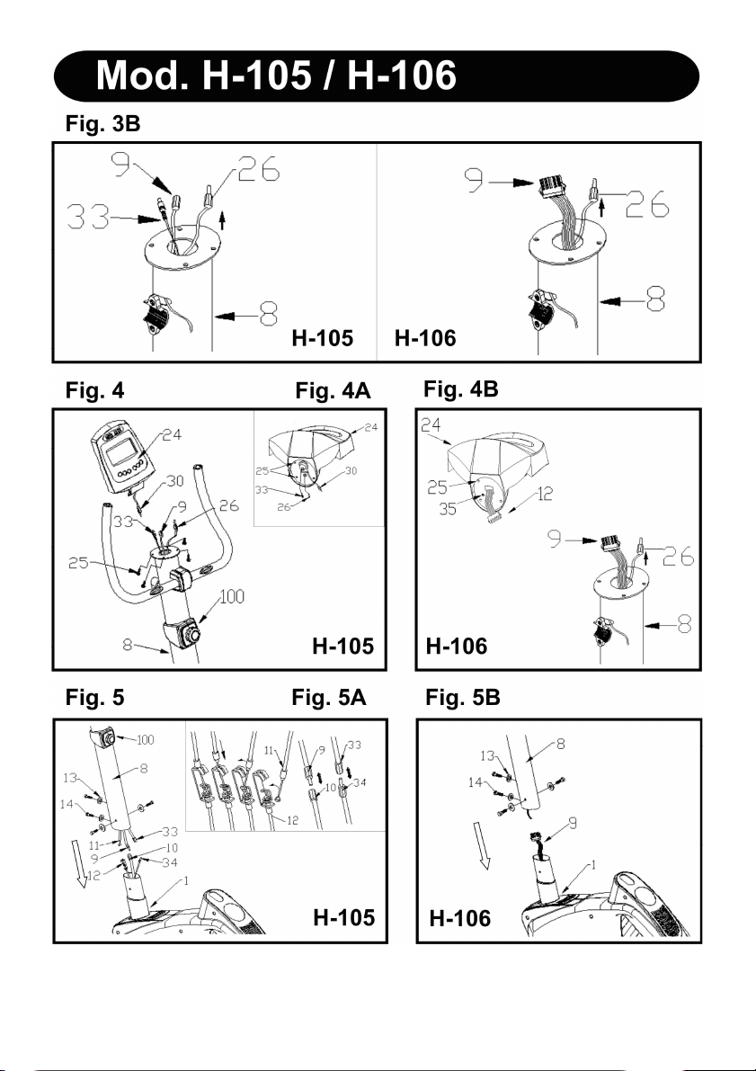
Posicione el manillar (15) en el tubo de
manillar (8), Fig.3, introduzca el cable
del hand-grip (26) por la ranura como
muestra en la Fig.3 A y B, y sáquelo por
la parte superior del tubo manillar.
Coloque la brida de fijación manillar
(16), coloque el tornillo (17) sin apretar
del todo, meta la arandela (20) y la
palanca de apriete manillar (19),
posicione el manillar y apriete
suavemente, coloque la tapa protección
de brida (18).
COLOCACION DEL MONITOR
Mod. H-105.- Coja el monitor (24),
suelte los cuatro tornillos (25) de la parte
inferior del monitor Fig.4 A, conexione
los terminales de los cables del reenvío
(30) que sale del monitor con el cable
(9) que sale del tubo manillar Fig.4.
Introduzca el terminal (26) que sale del
tubo manillar e introdúzcalo en la parte
inferior del monitor (26), seguido
introduzca el terminal (33) que sale del
tubo manillar e introdúzcalo en la parte
inferior del monitor (33), posicione el
monitor en el tubo de manillar, teniendo
cuidado de no pillar los cables y atornille
los cuatro tornillos (25) soltados
anteriormente.
Mod. H-106 Program.- Coja el monitor
(24), suelte los cuatro tornillos (25) de la
parte inferior Fig.(4 B), conexione el
terminal del cable que sale del monitor
(12) con el terminal del cable (9) que
sale del tubo manillar (8), seguido
introduzca el terminal (26) que sale del
tubo de manillar e introdúzcalo en el
terminal (35), posicione el monitor en el
tubo de manillar teniendo cuidado de no
pillar los cables y atornille los cuatro
tornillos (25) soltados anteriormente.
MONTAJE DEL TUBO MANILLAR
Mod. H-105.- Sujete el tubo manillar (8)
y conecte los terminales de los cables
del reenvío (9) y (10) y los terminales
(33) y (34) Fig.5. Coja el cable de
tensión (11) del tubo manillar (8) y
conéctelo al soporte de tensión inferior
(12) como muestra la Fig.5A.
6

Introduzca el tubo manillar (8) en
dirección a la flecha por el tubo saliente
del cuerpo principal (1), teniendo
cuidado de no pillar los cables,
compruebe si el mando de tensión (100)
funciona correctamente. Seguido
coloque los 3 tornillos (14) las arandelas
curvadas (13), alinee el tubo de manillar
y apriete fuertemente los tornillos.
Mod. H-106 Program.- Sujete el tubo
de manillar (8). Pase los cables del
reenvío (9) a través del tubo de manillar
con ayuda del cable suministrado
Fig.5B.
Introduzca el tubo manillar (8) en
dirección a la flecha por el tubo saliente
del cuerpo principal (1), teniendo
cuidado de no pillar los cables. Seguido
coloque los 3 tornillos (14) las arandelas
curvadas (13), aline el tubo de manillar y
apriete fuertemente los tornillos.
MONTAJE DEL SILLÍN
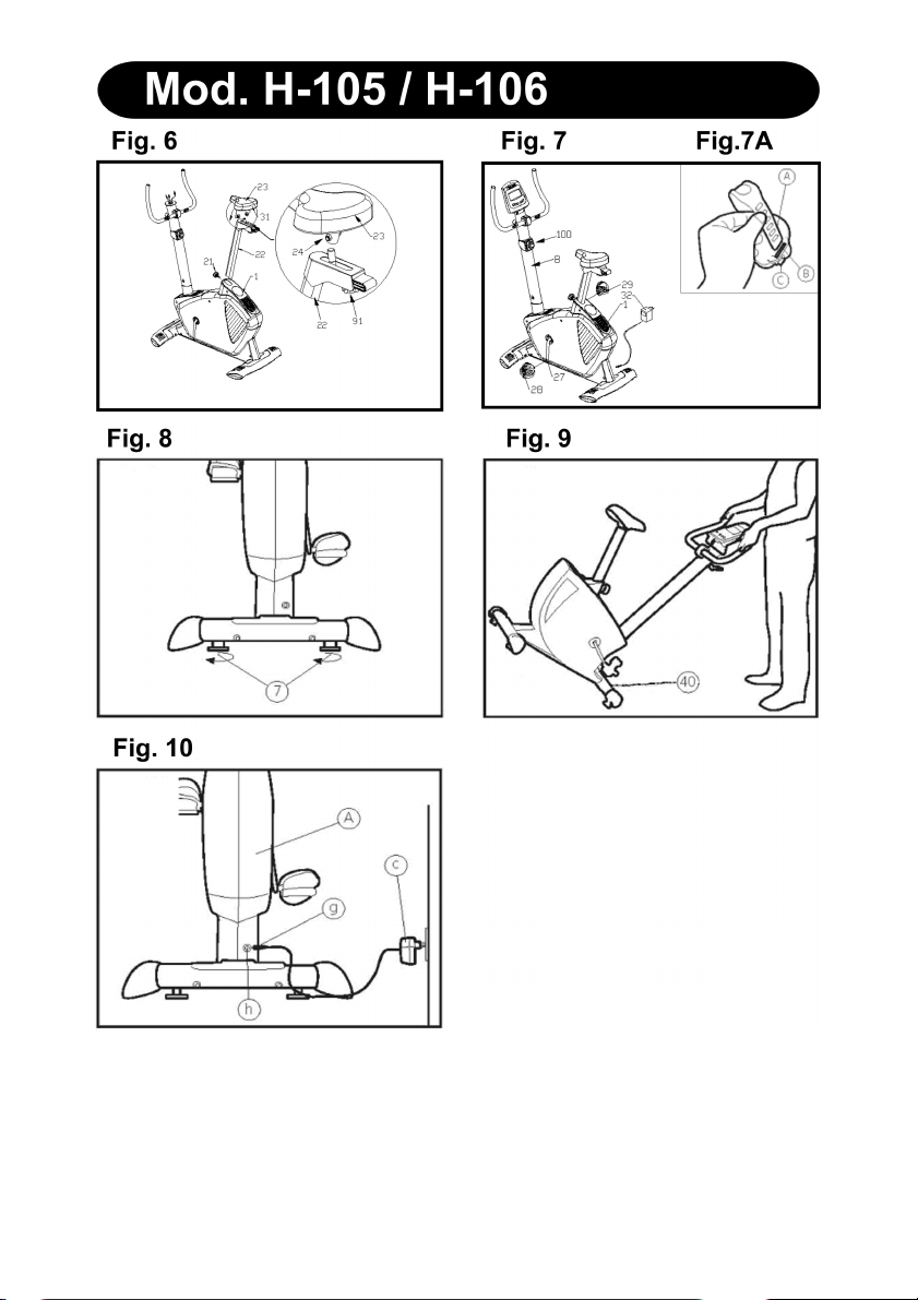
Coloque el sillín (23) en la tija (22) como
muestra la Fig. 6 teniendo en cuenta de
que los agujeros de la tija le queden
hacia la parte delantera del sillín,
coloque el sillín en posición y apriete las
tuercas (24) fuertemente. Seguido
introduzca el tubo de tija por el agujero
del cuerpo principal (1) coloque el pomo
de apriete de tija (21), fije la tija del sillín
en su posición cómoda con el pomo de
apriete (21) y apriete en sentido de las
agujas del reloj.
REGULACIÓN DE LA ALTURA
SILLÍN
Aflojando un poco el pomo de apriete
(21) de tija en sentido contrario a las
agujas del reloj y tirando del mismo
hacia atrás Fig.6, cuando lo tenga a la
altura adecuada para realizar el
ejercicio, suelte el pomo y se introducirá
en los agujeros de la tija. Apriete
fuertemente el pomo (21) en el sentido
de las agujas del reloj.
MONTAJE DE LOS PEDALES
Siga atentamente las instrucciones de
montaje de los pedales, una colocación
incorrecta podría dañar la rosca del
pedal o de la biela.
Las posiciones derecha e izquierda,
habrán de tomarse montado el usuario
en el sillín, en posición de hacer ejercicio.
El pedal derecho (29), marcado con la
letra (R), se enroscara en sentido de
giro agujas del reloj, en la biela derecha,
marcada con la letra (R). Apriete
fuertemente, Fig.7.
El pedal izquierdo (28), marcado con la
letra (L), se enroscará en el sentido
contrario a las agujas del reloj, en la
biela izquierda, marcada con la letra (L).
Apriete fuertemente, Fig.7.
Una vez colocados los pedales,
introduzca el extremo del calapies (A)
por la ranura del pedal (B) y
adaptándolo a su calzado sujételo en el
saliente del pedal (C), Fig.7A.
REGULACIÓN DE ESFUERZO
Mod. H-105.- Para un control de
esfuerzo regular de su ejercicio, este
aparato dispone de un mando de
tensión (100), colocado en el tubo
manillar (8), con distintas posiciones de
resistencia, Fig.7.
Para aumentar la resistencia del
pedaleo usted gire el mando de tensión
(100), en sentido de las agujas del reloj
(+), hasta conseguir que el esfuerzo de
su ejercicio es el ideal para usted. Para
disminuir la resistencia del pedaleo, gire
el mando de tensión (100), en sentido
contrario a las agujas del reloj (-).
7

NIVELACIÓN
Una vez colocada la unidad en su
lugar definitivo, para la realización del
ejercicio, compruebe que el
asentamiento en el suelo y su
nivelación sean correctos. Esto se
conseguirá roscando más o menos los
pies regulables (7) como muestra la
Fig.8.
MOVIMIENTO Y
ALMACENADO
La unidad está equipada con rueda
(40) lo que hace más sencillo su
movimiento.
La rueda que se encuentran en la
parte delantera de su unidad, le
facilitarán la maniobra de colocar su
unidad en el emplazamiento escogido,
levantando, ligeramente por la parte
delantera y empujando, como muestra
la Fig.9.
Guarde su máquina en un lugar seco
con las menores variaciones de
temperatura posible.
CONEXIÓN A LA RED
Transformador:
12V -1000 mAmp.
Introduzca la clavija de enganche (g)
del transformador (c) en el punto de
conexión (h), del cuerpo central (A),
(parte trasera inferior) y conecte el
transformador de corriente a la red de
220 V, Fig.10.
BH SE RESERVA EL DERECHO A
MODIFICAR LAS ESPECIFICACIONES DE SUS PRODUCTOS SIN
PREVIO AVISO.
Para cualquier consulta, no dude en
ponerse en contacto, llamando al
número de atención al cliente.
+34 902 170 258
sat@bhfitness.es
8

English
IMPORTANT SAFETY ADVICE
PRECAUTIONS
This bicycle has been designed and
constructed to provide maximum safety.
Nevertheless, certain precautions
should be taken when using exercise
equipment. Read the whole manual
before assembling and using the
bicycle. The following safety precautions
should also be observed:
1 Keep children away from this
equipment at all times. DO NOT leave
them unsupervised in the room where
this bicycle is kept.
2 It can only be used by one person at a
time.
3 If you experience dizziness, nausea,
chest pains or any other symptom while
using this appliance STOP the exercise.
SEEK MEDICAL ATTENTION
IMMEDIATELY
4 Use the appliance on a level, solid
surface. DO NOT use the bicycle
outdoors or close to water.
5 Keep your hands well away from any
of the moving parts.
6 Wear clothing suitable for doing
exercise. Do not use baggy clothing that
might get caught up in the bicycle.
Always wear running shoes or trainers
when using the machine.
7 This appliance must only be used for
the purposes described in this manual.
DO NOT use accessories that are not
recommended by the manufacturer.
8 Do not place sharp objects near the
machine.
9 Disabled people should not use the
machine without the assistance of a
qualified person or a doctor.
10 Do warm up stretching exercises
before using the equipment.
11 Do not use the bicycle if it is not
working correctly.
Caution: Consult your doctor before
beginning to use the bicycle. This advice
is especially important for those over 35
or suffering from health problems. Read
all of the instructions before using any
exercise equipment.
Keep these instructions safe for future
use.
GENERAL INSTRUCTIONS
Carefully read through the instructions
contained in this manual. It provides you
with important information about
assembly, safety and use of the
machine.
1 This unit has been designed for home
use. The weight of the user must not
exceed 130Kg.
2 Keep your hands well away from any
of the moving parts.
3 Parents and/or those responsible for
children should always take their curious
nature into account and how this can
often lead to hazardous situations and
behaviour resulting in accidents. Under
no circumstances should this appliance
be used as a toy.
4 The owner is responsible for ensuring
that anyone who uses the machine is
duly informed about the necessary
precautions.
5 Your unit can only be used by one
person at a time.
6 Use suitable clothing and footwear.
Make sure all laces/cords are tied
correctly.
9

ASSEMBLY INSTRUCTIONS
Take the unit out of its box and make
sure that all of the pieces are there
Fig.1.
1.(1) Main body; (8) Handlebar stem;
(22) Saddle post; (23) Saddle; (15)
Handlebar; (24) Monitor; (3) Rear
stabiliser bar; (2) Front stabiliser bar; a
box containing the following: (4) Slot
head bolts M-10; (5) Curved washer
M-10; (6) Cap nut M-10; (13) Curved
washer M-8; (14) Allen screw; (16)
handlebar bracket, (17) screw M8;
(18) Bracket cover; (19) Handlebar
lever; (20) Flat washer M-8; (21)
Saddle post knob; (36) Allen key; (37)
Double ended ring spanner; (38)
Pedal spanner; (28) Left pedal; (29)
Right pedal.
2.Take the rear stabiliser bar (3) and
position it on the machine’s rear stand
bracket, as shown in Fig.2, inserts
bolts (4), fit the curved washers (5) the
cap nuts (6) and tighten securely.
Take the front stabiliser bar with
wheels (2) and position it so that the
two red dots (A) line up, as shown in
Fig.2, insert bolts (4), fit the curved
washers (5) the cap nuts (6), and
tighten securely.
FITTING THE HANDLEBAR
Bring the handlebar (15) up to the
handlebar stem (8), Fig.3, insert the
hand-grip cable (26) in through the
slot as shown in Fig.3A and 3B, and
pull it out through the top of the
handlebar stem. Fit the handlebar
bracket (16), insert screw (17) and
hand tighten, put the washer (20) on
and the handlebar lever (19), position
the handlebar and tighten gently, then
fit the bracket cover (18).
FITTING THE MONITOR
Mod H-105.- Take the monitor (24) and
remove the four screws (25) from the
base of the monitor, Fig.4A, connect the
terminals for the feedback cables (30)
coming out of the monitor to the cable
(9) sticking up out of the handlebar
stem, Fig.4. Plug the terminal (26) which
is also sticking out of the handlebar
stem into the hole (26) on the base of
the monitor, then plug the terminal (33)
which is also sticking out of the
handlebar stem into the hole (33) on the
base of the monitor. Position the monitor
on the handlebar stem, making sure not
to catch any of the cables, and attach it
using the four screws (25) removed
previously.
Mod H-106 Program.- Take the monitor
(24), remove the four screws (25) from
the base, Fig.4B, connect the terminal
coming out of the monitor (12) with the
terminal for the cable (9) coming out of
the handlebar stem (8), next plug
terminal (26) which is also sticking up
from the handlebar stem into terminal
(35), position the monitor on the
handlebar stem, making sure not to
catch any of the cables, and attach it
using the four screws (25) removed
previously.
FITTING THE HANDLEBAR
STEM
Mod. H-105.- Hold the handlebar stem
(8) and connect the feedback cable
terminals (9) and (10) and the terminals
(33) and (34), Fig.5. Take the tension
cable (11) from the handlebar stem (8)
and connect it to the bottom tension
support (12), as shown in Fig.5A.
10

Insert the handlebar stem (8) onto the
boss on the main body (1) in the
direction of the arrow, making sure not
to catch any of the cables, and check
that the tension control (100) works
correctly. Next, line up the handlebar
stem with the holes and fit the 3 Allen
screws (14) and the curved washers
(13), tighten securely.
Mod. H-106 Program.- Hold the
handlebar stem (8). Pass the feedback
cable terminals (9) throught the
handlebar stem using the supplied
cable, Fig.5B.
Insert the handlebar stem (8) onto the
boss on the main body (1) in the
direction of the arrow, making sure not
to catch any of the cables. Next, line up
the handlebar stem with the holes and fit
the 3 Allen screws (14) and the curved
washers (13), tighten securely.
ATTACHING THE SADDLE
Place the saddle (23) onto the saddle
post (22), as shown in Fig.6, bearing in
mind that the holes on the saddle post
go at the front section of the saddle,
position the saddle correctly and tighten
nuts (24) securely. Now insert the
saddle post into the hole on the main
body (1), fit the saddle post knob (21)
and adjust the height of the saddle and
tighten it into position by turning the
saddle post knob (21) clockwise.
ADJUSTING THE SADDLE
HEIGHT
Loosen the saddle post knob (21) a
little, turning it anticlockwise, and pull it
back, Fig.6, adjust the height of the
saddle to suit the exercise and then
release the knob so that it slots back
into one of the holes on the saddle post.
Tighten the knob (21) securely by
turning it clockwise.
FITTING THE PEDALS
The assembly instructions for the pedals
must be followed to the letter, fitting
these incorrectly could damage the
screw thread on either the pedal or the
crank.
Right and left refer to the position that
the user adopts when sitting on the
saddle to do the exercises.
The right-hand pedal (29), marked with
the letter (R), screws onto the right-hand
crank, also marked with an (R), in a
clockwise direction. Tighten securely,
Fig.7.
The left-hand pedal (28), marked with
the letter (L), screws onto the left-hand
crank, also marked with an (L), in an
anti-clockwise direction. Tighten
securely, Fig.7.
Once the pedals have been fitted, insert
the end of the pedal clip (A) into the slot
on the pedal (B) adjusting it to your
footwear on the ledge of the pedal (C),
Fig.7A.
EXERTION SETTINGS.
Mod. H-105.- To provide an even level
of exertion during exercise, this
appliance is equipped with a tensioning
control (100), located on the handlebar
stem, offering various exertion settings,
Fig.7.
To increase pedal resistance turn the
tensioning control (100) clockwise (+)
until the exertion level best suits your
exercise requirements. To reduce pedal
resistance turn the tensioning control
(100) anticlockwise (-).
11

LEVELLING.
Once the unit has been placed into its
final position, make sure that it sits flat
on the floor and that it is level. This can
be achieved by screwing the adjustable
feet (7) up or down, as shown in Fig.8.
MOVEMENT & STORAGE
The unit is equipped with wheels (40)
to make it easier to move. The wheels
located at the front of your unit make it
easier to move it into a chosen
position, by lifting the rear of the unit up
slightly and pushing it, as shown in
Fig.9. Store your unit in a dry place,
preferably not subject to changes in
temperature.
MAINS CONNECTION
Transformer:
12 V- 1000 mAmp.
Insert the jack (g) on the transformer (c)
into the connection hole (h) on the main
body (A) (bottom, rear of the machine)
and then plug the transformer into a 220
V mains supply, Fig.10.
BH RESERVES THE RIGHT TO
MODIFY THE SPECIFICATIONS OF
ITS PRODUCTS WITHOUT PRIOR
NOTICE.
Do not hesitate to get touch with us if
you have any queries, by calling:
+44 0844 335 3988
service@bh-uk.co.uk
12
 Loading...