

BH Fitness G2385U installation Guide
G2382U-G2385U
Instrucciones de montaje y utilización
Instructions for assembly and use
Instructions de montage et utilisation
Montage- und Gebrauchsanleitung
Instruções de montagem e utilização
Istruzioni di montaggio e uso
Montage-en gebruiksinstrukties

Fig.1
Fig.2

Fig.3 Fig.4
Fig.5 Fig.6
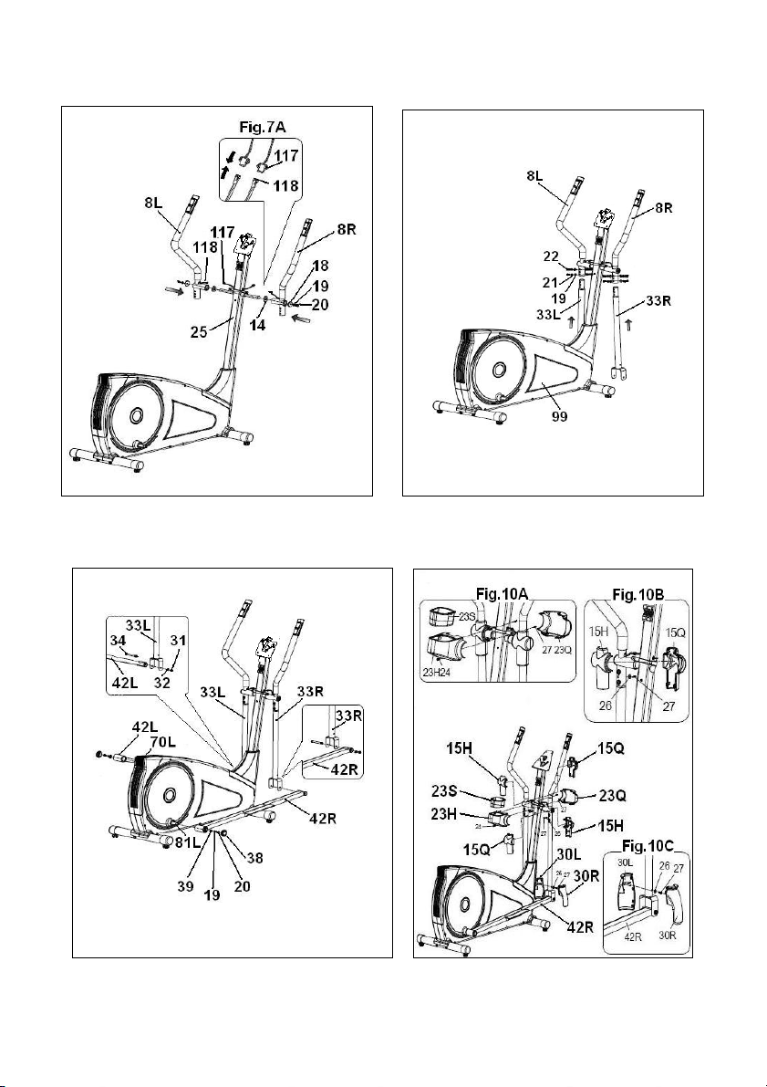
Fig.7 Fig.8
Fig.9 Fig.10

Fig.11 Fig.12
Fig.13 Fig.14

Fig.15 Fig.16

Español
INSTRUCCIONES DE
SEGURIDAD.-
Antes de comenzar cualquier
programa de ejercicio, consulte a su
médico. Se recomienda la realización
de un examen físico completo.
Trabaje en el nivel de ejercicio
recomendado, no llegue al
agotamiento. Si siente dolor o
molestias de cualquier tipo, pare el
ejercicio inmediatamente y acuda a su
médico.
Utilice el aparato sobre una superficie
sólida y nivelada, con algún tipo de
protección para el suelo o alfombra.
Por razones de seguridad, el equipo
deberá disponer a su alrededor de un
espacio libre no inferior a 0,5 m.
No permita a los niños jugar con este
aparato o a su alrededor. Mantenga
las manos alejadas de las partes en
movimiento.
Compruebe la elíptica antes de
comenzar el ejercicio, para
asegurarse de que se han montado
todas las piezas y que las tuercas,
tornillos, pedales y brazos se han
apretado correctamente antes del uso.
Ningún dispositivo de ajuste que
pueda interferir con el movimiento del
usuario debe sobresalir de la
máquina.
Especial cuidado debe tenerse con la
unión entre los tubos de pedales y los
brazos oscilantes superiores. Los
dedos pueden quedar atrapados en
este punto causando lesiones.
Utilice prendas y calzado apropiados
para el ejercicio físico. No utilice
prendas sueltas. No utilice calzado
con suela de cuero o tacones altos.
Este aparato ha sido probado y
cumple con la norma EN957 bajo la
clase H.B. El frenado es
independiente de la velocidad.
IMPORTANTE.-
Lea las instrucciones detenidamente
antes de proceder con el montaje.
Retire todas las partes del cartón de
embalaje e identifíquelas con respecto
al listado, para asegurarse de que no
falta ninguna.
No elimine el cartón hasta haber
montado la elíptica completamente.
Utilice el aparato siempre de acuerdo
con las instrucciones. Si encuentra
algún componente defectuoso durante
el montaje o comprobación del
aparato, o si oye algún ruido extraño
durante la utilización, pare.
No utilice este aparato hasta que se
haya solucionado el problema.
INSTRUCCIONES PARA EL
EJERCICIO.-
El uso de la ELÍPTICA le reportará
diferentes beneficios, mejorará su
condición física, tono muscular y,
junto con una dieta baja en calorías, le
ayudará a perder peso.
1 La fase de calentamiento.
Esta fase acelera la circulación
sanguínea en el cuerpo y pone a tono
los músculos para el ejercicio.
También reduce el riesgo de
calambres y lesiones musculares. Es
aconsejable realizar algunos ejercicios
de estiramiento, según se muestra
más adelante.
7
Realice cada estiramiento
aproximadamente durante 30
segundos, no fuerce los músculos. Si
siente dolor, PARE.
2. La fase de ejercicio.
En esta fase se realiza el esfuerzo
más importante. Tras el ejercicio
regular, los músculos de las piernas
aumentarán su flexibilidad. Es muy
importante mantener un ritmo
constante. El ritmo de ejercicio será lo
bastante alto para aumentar las
pulsaciones hasta la zona objetivo
que se muestra en el gráfico
siguiente.
Esta fase debería durar un mínimo de
12 minutos aunque se recomienda a
la mayoría de la gente comenzar con
períodos de 10-15 minutos.
3. La fase de relajación
Esta fase permite la relajación del
sistema cardiovascular y muscular. Se
trata de una repetición de los
ejercicios de calentamiento, por
ejemplo, reduciendo el ritmo, y
continuando aproximadamente 5
minutos. Repita los ejercicios de
estiramiento, y recuerde no forzar los
músculos.
Según transcurran los días, necesitará
entrenamiento más prolongados y de
mayor intensidad. Es recomendable
ejercitarse un mínimo de tres días por
semana, en días alternos.
Tonificación muscular.
Para tonificar los músculos durante el
ejercicio deberá seleccionar una
resistencia alta. Esto implicará una
mayor tensión sobre la musculatura
de las piernas y quizás deba reducir el
tiempo del ejercicio. Si también desea
mejorar su forma física general,
deberá cambiar su programa de
entrenamiento. Realice los ejercicios
de calentamiento y relajación de
costumbre, pero cuando esté llegando
al final de la fase de ejercicio,
aumente la resistencia para someter
sus piernas a un mayor esfuerzo.
Deberá reducir la velocidad para
mantener el ritmo cardíaco en la zona
objetivo.
Pérdida de peso.
En este caso, el factor importante es
el esfuerzo realizado. Cuando más
intenso y más prolongado sea el
trabajo, mayor será la cantidad de
calorías quemadas. Efectivamente, el
trabajo es el mismo que se realiza
para mejorar la condición físico, pero
el objetivo es diferente.
INDICACIONES GENERALES.-
Lea atentamente las instrucciones de
este manual. Este le da indicaciones
importantes sobre el montaje,
seguridad y uso de la máquina.
1 Esta unidad esta diseñada para uso
en casa. El peso de usuario no debe
exceder de 115Kg.
8

2 Mantenga las manos alejadas de
cualquiera de las partes móviles de la
unidad.
3 Los padres y otras personas
responsables de los niños deben de
tener en cuenta la naturaleza curiosa
de estos y que puede llevarles a
situaciones y conductas que pueden
resultar peligrosas. Esta unidad no ha
de utilizarse en ningún caso como
juguete.
4 Es responsabilidad del propietario
asegurarse que todos los usuarios de
la máquina estén adecuados e
informados sobre todas las
precauciones necesarias.
5 Su unidad sólo puede ser usada por
una persona al mismo tiempo.
6 Utilice prendas de vestir y calzado
adecuado. Átese los cordones
correctamente.
1.- INSTRUCCIONES DE
MONTAJE.-
Saque la unidad de la caja y
compruebe que tiene todas las piezas.
Se recomienda la ayuda de una
segunda persona para la
realización de este montaje.
Fig.1.
(99) Cuerpo principal.
(25) Tubo de remo.
(114) Monitor.
(8L) Brazo superior izquierdo.
(8R) Brazo superior derecho
(33L) Brazo inferior izquierdo.
(33R) Brazo inferior derecho.
(74) Tubo caballete trasero con tacos
regulables.
(95) Tubo caballete delantero con
ruedas.
(10) Tubo manillar.
(42L) Pedal pie izquierdo.
(42R) Pedal pie derecho.
(35L) Apoya píes Izquierdo.
(35R) Apoya pies Derecho.
(29) Tapa embellecedora inferior de
remo.
(15L) Tapa tubo de remo izquierda (L).
(15R) Tapa tubo de remo derecha (R).
(23H) Tapas cierre eje giro bastones.
(23Q)Tapas cierre eje giro bastones.
(30L) Tapas embellecedoras
inferiores, izquierda (L) de las rotulas
de bastones.
(30R) Tapas embellecedoras
inferiores, derecha (R) de las rotulas
de bastones.
(13) Carcasa protección brida.
(124) Transformador.
Fig.2.(9) Brida de fijación manillar.
(11) Arandela de muelle M-7.
(12) Tornillo allen M-7x30.
(18) Arandela plana M-8x36x3.
(19) Arandela de muelle M-8.
(20) Tornillos de M-8x20.
(21) Arandela curvada M-8.
(22) Tornillos de M-8x20.
(24) Tornillos de M-5x15.
(26) Arandela plana M-6x15.
(27) Tornillos de M-4x15.
(31) Tuercas autoblocantes M-10.
(32) Arandela plana M-10.
(34) Tornillo allen M-10x97.
(38) Tapones embellecedores.
(39) Arandela plana M-8.
(43) Arandela de muelle M-10.
(44) Tornillos de M-10x45.
(73) Tornillo allen M-8x70.
(103) Tornillos de M-5x12.
(111) Llave de allen.
(112) Llave mixta.
9

2.- COLOCACIÓN DE LOS
TUBOS CABALLETE.-
Acerque el tubo de caballete delantero
con ruedas (95) al cuerpo central (99),
posicionando las ruedas hacia delante
de la unidad, Fig.3, introduzca los
tornillos (73) y coloque la arandela
curvada (21), y apriete fuertemente.
Coja el tubo caballete trasero con
tacos regulables (74) y haciendo
coincidir los puntos, Fig.4 introduzca
los tornillos (73) coloque la arandela
(21), y apriete fuertemente.
3.- MONTAJE TAPA INFERIOR
EMBELLECEDORA DE REMO.-
Coja el tubo de remo (25) e introduzca
la carcasa embellecedora inferior de
remo (29) en dirección a la flecha
Fig.5.
4.- MONTAJE TUBO REMO.-
Una vez se ha colocado en el tubo de
remo la tapa embellecedora, acerque
el tubo de remo (25) hacia el tubo
saliente del cuerpo principal (99)
Fig.6.
Una el conector (116) que sale del
tubo remo (25), con el conector (119)
que sale del tubo saliente del cuerpo
central (99), Fig.6A.
Introduzca el tubo de remo (25) en el
saliente del cuerpo principal (99), en
dirección a la flecha, Fig.6, teniendo
cuidado de no pillar los cables.
Coloque los tornillos (22), junto con
las arandelas (19) y (21), Fig.6 y
apriete fuertemente.
Baje la tapa embellecedora (29) del
tubo remo (25) hasta el tubo base del
cuerpo central (99), Fig.6B.
5.- MONTAJE DE LOS BRAZOS.-
Introduzca el brazo izquierdo (8L)
(marcado con la letra L) en el eje giro
brazos (25) Fig.7, a continuación
coloque el brazo derecho (8R)
(marcado con la letra R) en el otro
extremo del eje giro brazos, coloque
en los extremos del eje los tornillos
con arandela (20) y las arandelas
planas (18-19) y ayudándose de las
dos llaves de tubo combinadas apriete
fuertemente.
Conexione los terminales (118) con el
(117) Fig.7A.
6.- MONTAJE BRAZOS DE
PIES.-
Coja el brazo de pies izquierdo (33L)
(marcado con la letra L) e introdúzcalo
en el saliente del brazo superior
izquierdo (8L) haciendo coincidir las
letras (L), Fig.8, coloque los tornillos
(22) y las arandelas (19-21) y apriete.
Seguido realice el mismo montaje con
el brazo de pies derecho (33R).
7.- MONTAJE DE LOS PIES.-
Coja el pedal derecho (42R), Fig.9
(marcado con la letra R) e
introdúzcalo en el eje de la biela (81R)
(parte derecha de la máquina).
Seguido coja las arandelas (19) y (39)
y el tornillo (20) y atornille
fuertemente.
Finalmente, coloque los tapones (38).
Coja el pedal izquierdo (42L) Fig.9
(marcado con la letra L) e introdúzcalo
en el eje (70L) parte izquierda de la
máquina.
Seguido coja las arandelas (19) y (39)
el tornillo (20) y atornille fuertemente.
Finalmente, coloque los tapones (38).
Coja el pie derecho (42R, posiciónelo
en la “U” de la parte inferior del brazo
derecho (8R), Fig.9.
10

Introduzca el tornillo (34) como de
indica en la Fig.9 y coja la arandela
plana (32) y la tuerca autoblocante
(31) y apriete fuertemente.
Coja el pie izquierdo (42L),
posiciónelo en la “U” de la parte
inferior del brazo derecho (8L), Fig.9.
Introduzca el tornillo (34) como de
indica en la Fig.9 y coja la arandela
plana (32) y la tuerca autoblocante
(31) y apriete fuertemente.
8.- MONTAJE TAPAS LATERALES
EJE GIRO BRAZOS.-
Coja las tapas (15R) marcadas en el
interior con la letra (R), y posiciónelas
en el extremo del eje con los brazos en
la parte derecha, según muestra la
Fig.10B a continuación, atorníllelas con
los tornillos (27).
Realice el mismo montaje en el otro
extremo del eje con las tapas (15L)
marcadas en el interior con la letra (L).
9.- MONTAJE TAPAS
CENTRALES.-
Coja la tapa trasera (23Q) y la tapa
delantera (23H), posiciónelas en el
tubo de remo (25) Fig.10A. Y a
continuación atorníllelas con los
tornillos (24) y (27).
10.- MONTAJE TAPAS
LATERALES EJE GIRO BRAZOS
CON LOS PIES.-
A continuación coloque las tapas
embellecedoras (30L) y (30R) de los
pies con la parte inferior de los
bastones, en el lado derecho Fig.10C.
Atorníllelas con los tornillos (27).
Seguido realice la misma operación
con las otras tapas (30L) y (30R) en el
lado izquierdo.
11.- MONTAJE DE LOS
REPOSAPIÉS.-
Posicione el reposapiés derecho
(35R, marcado con la letra R) sobre el
pie derecho (42R) de la unidad, Fig.11
(la posición izquierda y derecha en la
unidad es siempre en la posición de
hacer el ejercicio).
Coloque los tornillos (44), las
arandelas (43) y las arandelas de
muelle (32) y apriete fuertemente.
Seguido posicione el reposapiés
izquierdo (35L marcado con la letra L)
sobre el pie izquierdo (42L), coloque
los tornillos (44), las arandelas (43) y
las arandelas de muelle (32) y apriete
fuertemente.
12.- COLOCACIÓN DEL
MANILLAR.-
Posicione el manillar (10) en el tubo
de manillar (25), Fig.12. Coloque la
brida de fijación manillar (9), coloque
el tornillo (12) sin apretar del todo,
meta la arandela (11), posicione el
manillar y apriete suavemente,
coloque la tapa protección de brida
(13).
13.- MONTAJE MONITOR.-
COLOCACIÓN CABLE REENVÍO.
Tome el cable (116) que sale por la
parte superior del tubo de remo (25)
Fig.13 y enchúfelo al conector del
electrónico (114) Fig.13.
COLOCACIÓN CABLE HAND-GRIP.
Tome los conectores (117) del
HandGrip y enchúfelos a los
conectores situados en la parte
trasera del monitor (114), como
muestra la Fig.13.
11

COLOCACIÓN DEL MONITOR.
Seguido coloque el monitor (114), en
dirección de la flecha sobre la chapa
del tubo remo (25) Fig.13,
introduciendo los cables en el interior
del tubo remo y teniendo cuidado de
no pillar los cables. Coloque los
tornillos (103).
ATENCIÓN:
Es muy importante el reapretar todos
los tornillos que han intervenido en el
montaje de la maquina, a la semana
aproximadamente de uso de la
maquina, con ello evitaremos ruidos
raros y posibles averías.
NIVELACIÓN.-
Una vez colocada la unidad en su
lugar definitivo, para la realización del
ejercicio, compruebe que el
asentamiento en el suelo y su
nivelación sean correctos. Esto se
conseguirá roscando más o menos los
pies regulables (72) como muestra la
Fig.14.
MOVIMIENTO Y ALMACENADO.-
La unidad está equipada con ruedas
(96) lo que hace más sencillo su
movimiento. Las ruedas que se
encuentran en la parte delantera de
su unidad, le facilitarán la maniobra de
colocar su unidad en el
emplazamiento escogido, levantando,
ligeramente por la parte delantera y
empujando, como muestra la Fig.15.
Guarde su máquina en un lugar seco
con las menores variaciones de
temperatura posible.
CONEXIÓN A LA RED.-
Introduzca la clavija de enganche (m)
del transformador (124) en el punto de
conexión (k), del cuerpo central (99),
(parte trasera inferior) y conecte el
transformador de corriente a la red de
220 V, Fig.16.
Para cualquier consulta, no dude en
ponerse en contacto con el
(S.A.T).Servicio de Asistencia
Técnica, llamando al teléfono de
atención al cliente (ver página final del
presente manual).
BH SE RESERVA EL DERECHO A
MODIFICAR LAS ESPECIFICACIONES DE SUS PRODUCTOS SIN
PREVIO AVISO.
12

English
SAFETY INSTRUCTIONS.-
Consult your doctor before starting
any exercise program. It is advisable
to undergo a complete physical
examination.
Work at the recommended exercise
level, do not overexert yourself. If you
feel any pain or discomfort, stop
exercising immediately and consult
your doctor.
Use the appliance on a solid, fl at
surface, with some type of protection
for the floor or carpet. In the interest of
safety, the equipment must have at
least 0.5 metres of free space around
it.
Do not allow children to play with the
equipment or in the immediate vicinity.
Keep your hands well away from any
of the moving parts.
Check the elliptical trainer before
starting the exercise; to make sure
that all of the parts are attached and
that the nuts, bolts, pedals and focus
bars have been tightened correctly
prior to use.
Any adjustment device that could
interfere with the user’s movement
should not be left projecting.
People should be careful with the joint
place between pedal tubes and swing
bar tubes. If fingers get stuck, injuries
could be caused.
Wear appropriate clothing and
footwear for the exercise. Do not use
loose clothing. Do not wear leather
soled shoes or footwear with high
heels.
This appliance has been tested and it
complies with standard EN957 under
class H.B. Braking is independent of
speed.
IMPORTANT.-
Read the instructions carefully before
proceeding to assemble the
equipment.
Remove all the parts from the
cardboard packaging and check them
against the parts list to ensure that
there is nothing missing.
Do not throw the cardboard away until
the elliptical trainer is fully assembled.
Always use the appliance in
accordance with the instructions. If
you discover any defective component
while assembling or checking the
equipment, or if you hear any strange
noise during exercise then stop. Do
not use the appliance until the
problem has been resolved.
EXERCISE INSTRUCTIONS.-
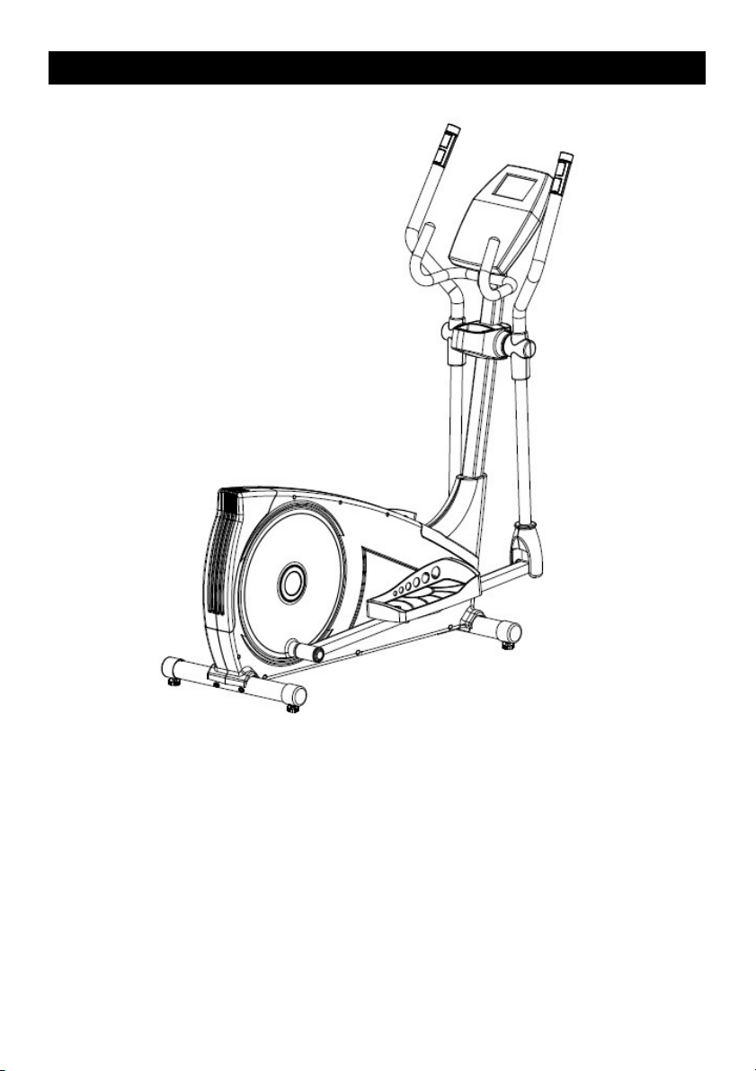
Use of the ELLIPTICAL TRAINER
offers various benefi ts; it will improve
fitness, muscle tone and when used in
conjunction with a calorie controlled
diet it will help you to lose weight.
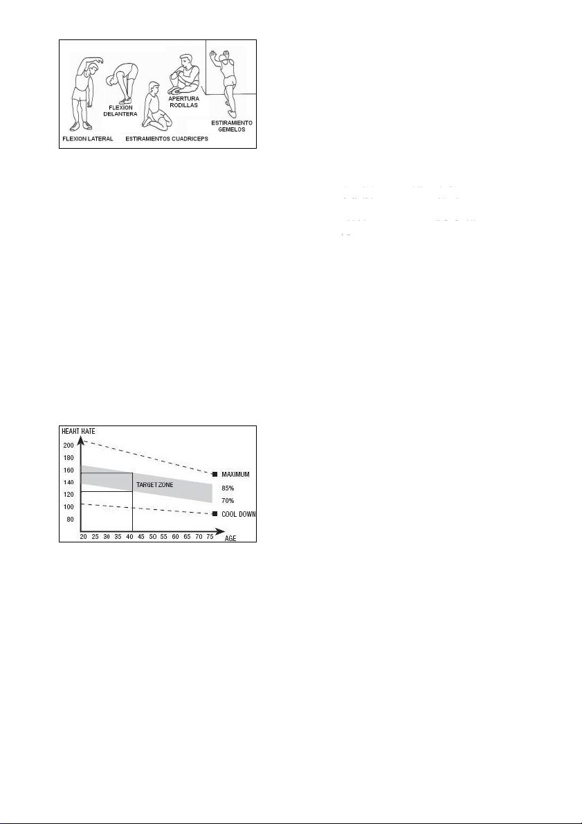
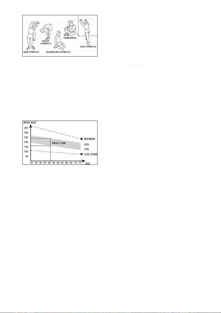
1,Warm-up phase
This phase speeds up the body’s
blood circulation and gets the muscles
ready for exercise. It also reduces the
risk of cramp and sprains. It is
advisable to do some stretching
exercises, as shown below. Each
stretch should last approximately 30
seconds, do not overexert the
muscles. If you feel pain, STOP.
13
2. Exercise phase
This phase requires the greatest
physical exertion. After regular
exercise the leg muscles will become
more flexible. It is important to keep
the rhythm constant. The rhythm of
the exercise should be fast enough to
bring the heart rate into the target
area, as shown on the following graph:
This phase should last at least 12
minutes, although it is advisable for
most people to start off with sessions
of 10-15 minutes.
3. Cool-down phase
This phase allows the cardiovascular
and muscle system to relax. It consists
of repeating the warm-up exercises,
i.e. reducing the rhythm and
continuing for approximately 5
minutes. Repeat the stretching
exercises but remember not to
overexert the muscles.
Eventually your training sessions will
have to become longer and more
intensive. It is advisable to exercise at
least three days per week, on
alternate days.
Muscle toning
You should select a high exertion level
in order to tone muscles during
exercise. This entails greater stress on
the leg muscles, so it may be wise to
reduce exercise times. If you also wish
to improve your overall fi tness then
you should change your training
program. Do the warm-up and
cooldown exercises as normal but
when you are reaching the end of the
exercise phase, increase the exertion
level in order to make your legs work
harder. You should reduce speed in
order to keep your heart rate within
the target area.
Weight loss
In this case the important factor is the
effort made. The more intense and the
longer the session, the greater the
number of calories burned. Even
though you are dong the same work
as you do to improve fitness, the
objective has changed.
GENERAL INSTRUCTIONS.-
Carefully read through the instructions
contained in this manual. It provides
you with important information about
assembly, safety and use of the
machine.
1 This unit has been designed for
home use. The user weight does not
have to exceed 115Kg.
2 Keep your hands well away from
any of the moving parts.
3 Parents and/or those responsible for
children should always take their
curious nature into account and how
this can often lead to hazardous
situations and be haviour resulting in
accidents. This unit does not have to
be used in any case like toy.
14

4 The owner is responsible for
ensuring that anyone who uses the
machine is duly informed about the
necessary precautions.
5 Your unit can only be used by one
person at a time.
6 Use suitable clothing and footwear.
Tie up your shoelace correctly.
1. ASSEMBLY INSTRUCTIONS.-
Take the unit out of its box and make
sure that all of the pieces are there:
The assistance of a second person
is recommended when assembling
this unit Fig.1.
(99) Main body.
(25) Main post.
(114) Monitor.
(8L) Top focus bar, left.
(8R) Top focus bar, right.
(33L) Bottom focus bar, left.
(33R) Bottom focus bar, right.
(74) Rear stabiliser bar with
adjustable feet.
(95) Front stabiliser bar with wheels.
(10) Handlebar tube.
(42L) Pedal left foot.
(42R) Pedal right foot.
(35L) Left footrest.
(35R) Right footrest.
(29) Bottom post cover.
(15L) Covers main post left (L).
(15R) Covers main post right (R).
(23H) Focus bar spindle covers (L).
(23Q) Focus bar spindle covers (R).
(30L) Bottom trim covers, left for the
knuckle joints on the focus bars.
(30R) Bottom trim covers, right for the
knuckle joints on the focus bars.
(13) Bracket cover.
(124) Transformer.
Fig.2
(9) Handlebar bracket.
(11) Spring washer M-7.
(12) Allen screw M-7x30.
(18) Flat washer M-8x36x3.
(19) Spring washer M-8.
(20) Screws M-8x20.
(21) Curved washer M-8.
(22) Screws M-8x20.
(24) Screws M-5x15.
(26) Flat washer M-6x15.
(27) Screws M-4x15.
(31) Self-locking nuts M-10.
(32) Flat washer M-10.
(34) Allen screw M-10x97.
(38) Head caps.
(39) Flat washer M-8.
(43) Spring washer M-10.
(44) Screws M-10x45.
(73) Allen screw M-8x70.
(103) Screws M-5x12.
(111) Allen key.
(112) Box spanner.
2. FITTING THE STABILISER
BARS.-
First, lift the front of the machine and
rest it on a prop, such as the
packaging that you have just removed.
Bring the front stabiliser bar with
wheels (95) to the main body (99)
positioning the wheels at the front of
the unit, Fig.3, insert the screws (73),
fit the curved washer (21), and tighten
securely.
Take the rear stabiliser with adjustable
feet (74), and line up the dots Fig.4.
Insert the screws (73), fit the washer
(21) and nuts (8), and tighten
securely.
15

3. FITTING THE BOTTOM POST
COVER.-
Take the main post (25) and insert the
bottom post cover (29) in the direction
of the arrow, Fig.5.
4. FITTING THE MAIN POST.-
Once the bottom post cover, is fitted,
bring the main post (25) up to boss on
the main body (99), Fig.6.
Plug connector (116), coming out of
the main post (25), into connector
(119), coming out of the boss on the
main body (99), Fig.6A.
Slip the main post (25) over the boss
(99) on the main body in the direction
of the arrow, Fig.6, making sure not to
snag any of the cables.
Fit the screws (22), along with the
washers (19) and (21), Fig.6, and
tighten securely.
Lower the bottom trim section (29) for
the main post (25) down over the boss
section of the main body (99), Fig.6B.
5.- FITTING THE FOCUS BARS.-
Insert the left focus bar (8L) (marked
with the letter “L”) onto the focus bar
spindle (25), Fig.7, then fit the right
focus bar (8R) (marked with the letter
“R”) on the other end of the spindle.
Fit the washered bolts (20) and the flat
washers (18-19) and with the help of
the box spanners tighten securely.
Connect the terminals (118) and (117),
Fig.7A.
6.- MOUNTING THE FOOT ARMS.-
Take the left foot arm (33L) (marked
with the letter L) and insert it in the left
upper arm (8L) ensuring that the letters
coincide (L), Fig.8 insert screws (22)
and the flat washers (19-21) and tighten.
Follow the same procedure for the
right foot arm (33R).
7.- FITTING THE FEET.-
Take the right pedal (42R), Fig.9,
(marked with the setter “R”) and slide
it onto the crank shaft (81R) on the
right- hand side of the machine.
Now take washers (32) and (39) and
bolt (20) and tighten securely.
Finally, fit the caps (38).
Take the left pedal (42L), Fig.9,
(marked with the setter “L”) and slide it
onto the shaft (70L) on the left-hand
side of the machine.
Now take washer (19) and (39) and
bolt (20) and tighten securely.
Finally, fit the caps (38).
Take the right foot (42R) and position
it in the "U" of the lower right arm (8R)
Fig.9, insert screw (34) as shown in
Fig 9 and take flat washer (32) and
self-locking nut (31) and tighten firmly.
Take the left foot (42L), and position it
in the "U" of the lower left arm (8L)
Fig.9, insert screw (34) as shown in
Fig.9 and take flat washer (32) and
self-locking nut (31) and tighten firmly.
8.- FITTING THE FOCUS BAR
SIDE COVERS.-
Take the covers (15R), marked on the
inside with the letter “R”, and position
them at the spindle end with the bars
on the right hand side, as shown in
Fig.10B. Now use screws and (27) to
attach them.
Carry out the same procedure at the
other end of the bar using the covers
(15L) marked on the inside with the
letter “L”.
16

9.- FITTING THE CENTRAL
COVERS.-
Take the front (23H) and rear (23Q)
covers and position them on the main
post (25), Fig.10A. Now use the screws
(24) and (27) to attach them to the
post.
10.- FITTING THE FOCUS BAR
SIDE COVERS TO THE FOOT
BARS.-
Next fit the footrest covers (30L) &
(30R) with the bottom of the joints on
the right side, Fig.10C. Use screws
(27) to screw them together.
Then do the same with the other
covers (30L) & (30R) on the left-hand
side.
11. FITTING THE FOOTRESTS.-
Position the right footrest (35R marked
with the letter “R”) on top of the unit’s
right foot (42R), Fig.11, (left and right
refers to the user’s position doing
exercise) .
Refit the screws (44), the washers
(43) and the spring washers (32), and
tighten securely.
Next, position the left footrest (35L
marked with the letter “L”) on top of
the left foot (42L), refit the screws
(44), the washers (43) and the spring
washers (32), and tighten securely.
12. FITTING THE HANDLEBAR.-
Bring the handlebar (10) up to the
handlebar stem (25), Fig.12. Fit the
handlebar bracket (9), insert screw
(12) and hand tighten, put the washer
(11), position the handlebar and
tighten gently, then fit the bracket
cover (13).
13. FITTING MONITOR.-
ATTACHING THE FEEDBACK
CABLE.
Take hold of the cable (116), which is
sticking up out of the main post (25),
Fig.13, and plug it into the connector
of the electronic unit (114), as shown
in Fig.13.
FITTING THE HAND-GRIP CABLE.
Take hold of the Hand-grip connectors
(117), sticking out of the main post
(25), and plug them into the
connectors located at the back of the
monitor (114), as shown in Fig.13.
ATTACHING THE MONITOR.-
Next, slide the front of the monitor
(114) onto the plate on top of the main
post (25) in the direction of the arrow,
Fig.13, push the cables down into the
main post making sure not the pinch
any of the cables. Replace the screws
(103).
ATTENTION:
It is important to retighten all of the
screws involved in assembling the
machine after approximately a week of
use as this will prevent any strange
noises and possible damage.
LEVELLING.-
Once the unit has been placed into its
final position, make sure that it sits fl
at on the fl oor and that it is level. This
can be achieved by screwing the
adjustable feet (72) up or down, as
shown in Fig.14.
17
 Loading...