


Network

NETWORK COMPASS USER MANUAL
CONTENTS
GENERAL INTRODUCTION TO B&G NETWORK.........................................................2
INTRODUCTION TO NETWORK COMPASS.................................................................3
COMPASS DISPLAY UNIT.............................................................................................4
EXAMPLE SYSTEMS USING NETWORK COMPASS...................................................4
INITIAL POWER-UP........................................................................................................5
SETTING THE DISPLAY BACK LIGHTING ...................................................................6
THE OFF COURSE DISPLAY.........................................................................................7
SETTING THE COURSE MEMORIES ............................................................................8
THE XTE DISPLAY .........................................................................................................9
THE RUDDER DISPLAY...............................................................................................10
THE HEAD/LIFT DISPLAY ...........................................................................................11
USING THE TIMER.......................................................................................................12
SETTING THE TIMER...................................................................................................13
ENABLING/DISABLING THE TIMER BEEPS..............................................................13
ENABLING THE OFF COURSE ALARM......................................................................14
SETTING THE COMPASS DAMPING ..........................................................................14
SETTING THE COMPASS OFFSET.............................................................................15
SETTING THE VARIATION ..........................................................................................15
SETTING THE DISPLAY FOR TRUE OR MAGNETIC READINGS .............................16
ENABLING THE HEAD/LIFT MODE.............................................................................16
SELECTING THE DISPLAY MODE..............................................................................17
CALIBRATING THE COMPASS...................................................................................17
OPERATION WITH AUTOPILOTS ...............................................................................18
TROUBLESHOOTING ..................................................................................................19
INSTALLATION ............................................................................................................20
SITING THE FLUXGATE ..............................................................................................21
INSTALLATION DATA..................................................................................................22
SPECIFICATIONS.........................................................................................................23
1

NETWORK COMPASS USER MANUAL
GENERAL INTRODUCTION TO B&G NETWORK
Welcome to the B&G Network system. This World beating series of intelligent
navigational instruments has been brought to you through a combination of scientific
innovation and high quality production to create a computerised data system you can
trust. As an intelligent system each unit can be used by itself to display specific data,
alternatively any combination of units can be linked into a Network with units processing
their own data or acting as repeaters for data from other units. This Network provides a
comprehensive navigational system. Screened cables combined with the latest
technology provide protection from interference between units and other systems.
The Network system is continuously expanding your options and currently consists of the
following units:
INSTRUMENTS
Network SPEED
Network DEPTH
Network QUAD
Network WIND
Network TACK
Network DATA
Network COMPASS
NAVIGATIONAL AIDS
Network NAV
Network GPS
LCD CHART
AUTOPILOTS
Network PILOT
2

NETWORK COMPASS USER MANUAL
INTRODUCTION TO NETWORK COMPASS
The Network COMPASS unit uses the latest advances in electronics and magnetic
fluxgate technology to display a true or magnetic heading, as well as Off Course, Cross
Track Error (XTE)*, Rudder Angle* and Head/Lift information on an easy to read Liquid
Crystal Display (LCD). Five keys on the unit select the displayed data, calibration factors
and alarms.
It can operate as a standalone compass display or as part of an Integrated B&G Network
Instrument System. The unit can also operate as a repeater of course data received via
the Network. These connections plug directly into the rear of the display.
The Network COMPASS includes two adjustable alarms:
• Off course alarm
• Head alarm
An internal alarm buzzer will sound and the display will flash -A- when the alarm
condition is met. Other Network instruments will also sound their alarms and flash their
displays, and the alarm condition can be cleared by pressing any key on any Network
instrument.
Additionally a racing timer with alarm signals at set intervals is included in the unit.
* These functions will only appear if the relevant sensors (for example, GPS
plus
or
Network PILOT) are in the system.
3
NETWORK COMPASS USER MANUAL
COMPASS DISPLAY UNIT
PORT
CRSE 1
STEER
MODE
TIMER LOCK SETUP LIGHTS
ENTER
Network COMPASS
30 20 10 302010
OFFCOURSE
EXAMPLE SYSTEMS USING NETWORK COMPASS
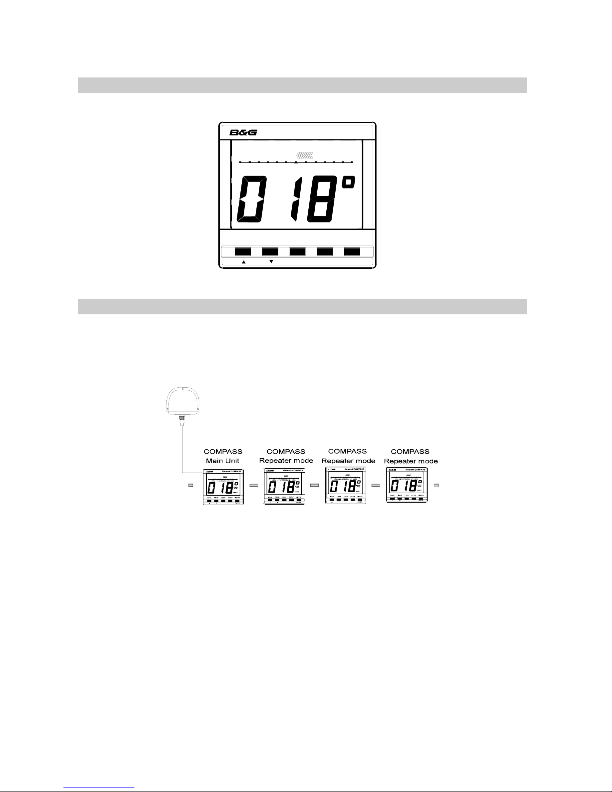
Up to four COMPASS units can be connected to the system. Only one of these should be
linked to a fluxgate and set to transducer mode, the others must be set to repeater mode.
Refer to SELECTING THE DISPLAY MODE to see how to change modes.
In this configuration the main unit controls all the measurement parameters such as
offset and damping. These parameters can be changed via the keyboard on any of the
units: repeaters will send appropriate network messages to the main unit so that it can
keep its parameters up to date.
4
NETWORK COMPA SS USER MANUAL
5
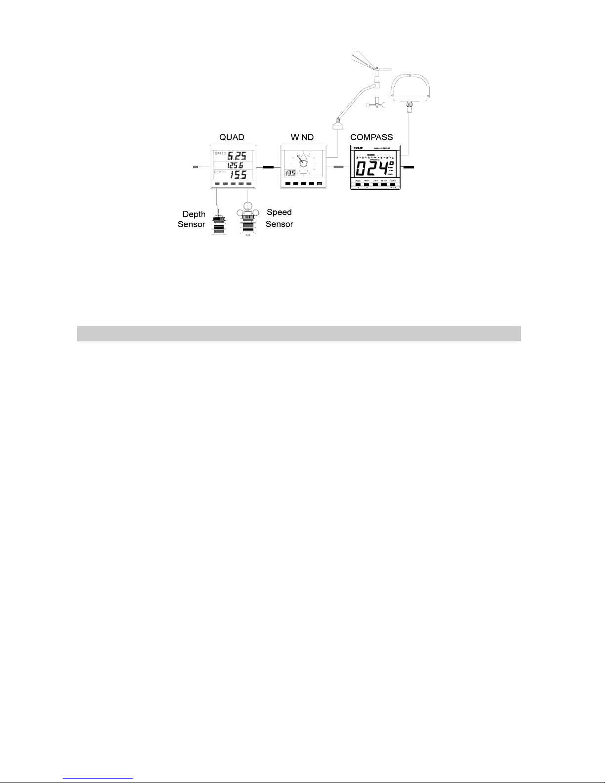
In this configuration the COMPASS unit is set to transducer mode and will send heading
data to the other instruments. The other Network units are also transmitting data that the
COMPASS may be able to use. For example, if the COMPASS is set to Head/Lift mode
the wind angle data will cause it to switch between port and starboard tacks
automatically.
INITIAL POWER-UP
When a COMPASS unit is powered up for the first time it will automatically adjust itself to
the phase characteristics of the fluxgate sensor, so if it is to be used with a fluxgate (that
is, in transducer mode) the fluxgate should be installed and connected before applying
power. Refer to the installation guidelines at the back of this manual for advice on
optimum siting of the fluxgate. During the phase adjustment the display will show PHS
and a pair of chevrons to indicate which of the phase settings is currently being tested.
When all the phase settings have been tested the optimum one is selected and stored for
future use. The complete phase adjustment procedure takes about 20 seconds.
The same phase adjustment is also carried out immediately before a calibration swing
(see CALIBRATING THE COMPASS, page 17).
NETWORK COMPASS USER MANUAL
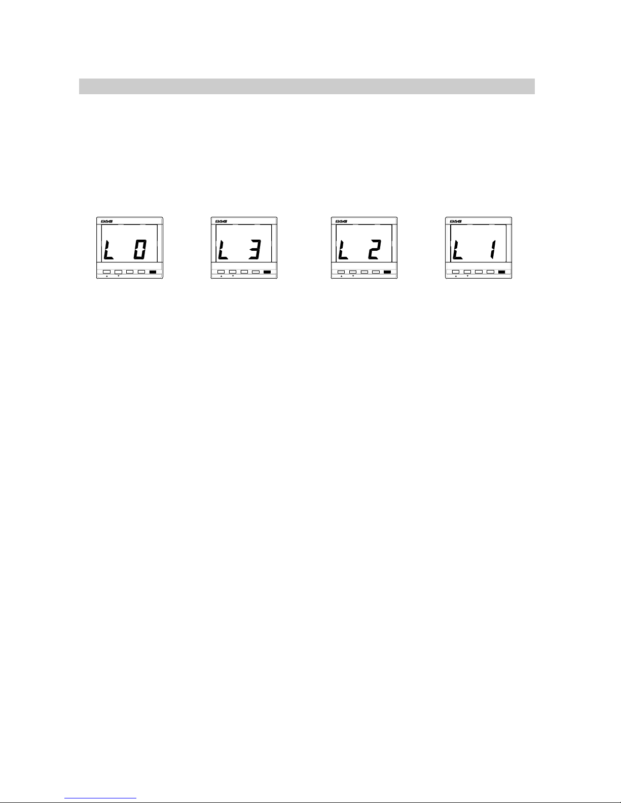
SETTING THE DISPLAY BACK LIGHTING
The Network COMPASS display back light has three brightness settings or off. Pressing
the LIGHTS key cycles through these in the following order:
• L 0 OFF
• L 3 High
• L 2 Medium
• L 1 Low
MODE
TIMER LOCK SETUP LIGHTS
ENTER
Network COMPASS
MODE
TIMER LOCK SETUP LIGHTS
ENTER
Network COMPASS
MODE
TIMER LOCK SETUP LIGHTS
ENTER
Network COMPASS
MODE
TIMER LOCK SETUP LIGHTS
ENTER
Network COMPASS
6
NETWORK COMPASS USER MANUAL
THE OFF COURSE DISPLAY
Pressing the MODE key will cycle the display between Off Course, Cross Track Error
(XTE) if a Network GPS
plus
is fitted, Rudder angle if a Network PILOT is fitted and the
Head/Lift display (if enabled).
MODE
TIMER LOCK SETUP LIGHTS
ENTER
Network COMPASS
LIFT
30 20 10 302010
PORT
MODE
TIMER LOCK SETUP LIGHTS
ENTER
Network COMPASS
30 20 10 302010RUDDER
MODE
TIMER LOCK SETUP LIGHTS
ENTER
Network COMPASS
101.00.1XTE10 1.0 0.1
STBD
CRSE 1
STEER
MODE
TIMER LOCK SETUP LIGHTS
ENTER
Network COMPASS
30 20 10 302010
OFFCOURSE
STBD
CRSE 1
STEER
The XTE display
with GPSplus
The Rudder
display with
Network Pilot
The Off Course
display
The Head/Lift
display if
enabled
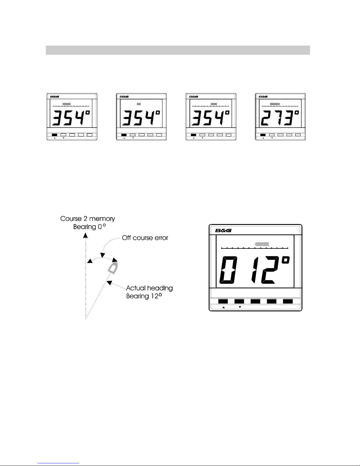
The unit will autodetect the presence of a GPS or PILOT on the Network and will activate
the displays accordingly. The Off Course display is used to show the difference between
the current heading and the heading stored in the selected course memory (see
SETTING THE COURSE MEMORIES).
MODE
TIMER L OCK SETUP LIGHTS
ENTER
Network COMPASS
30 20 10 302010
OFFCOURSE
PORT
CRSE 2
STEER
In this instance the vessel is heading starboard of the setting in the course 2 memory and
the display shows the current bearing. The Off Course scale is visible below the bar
graph which points to port, and the legends STEER and PORT indicate the direction in
which to steer to correct the error.
The Off Course scale indicates how many degrees the vessel is from its intended
heading.
7
 Loading...