

Page 1
16
OPERATING INSTRUCTIONS MCW DIGITAL
Thank you for selecting the MCW Digital wireless conference system. Please take some time to read carefully through this
manual before setting up the equipment.
1. MCW-D 100 Control Unit
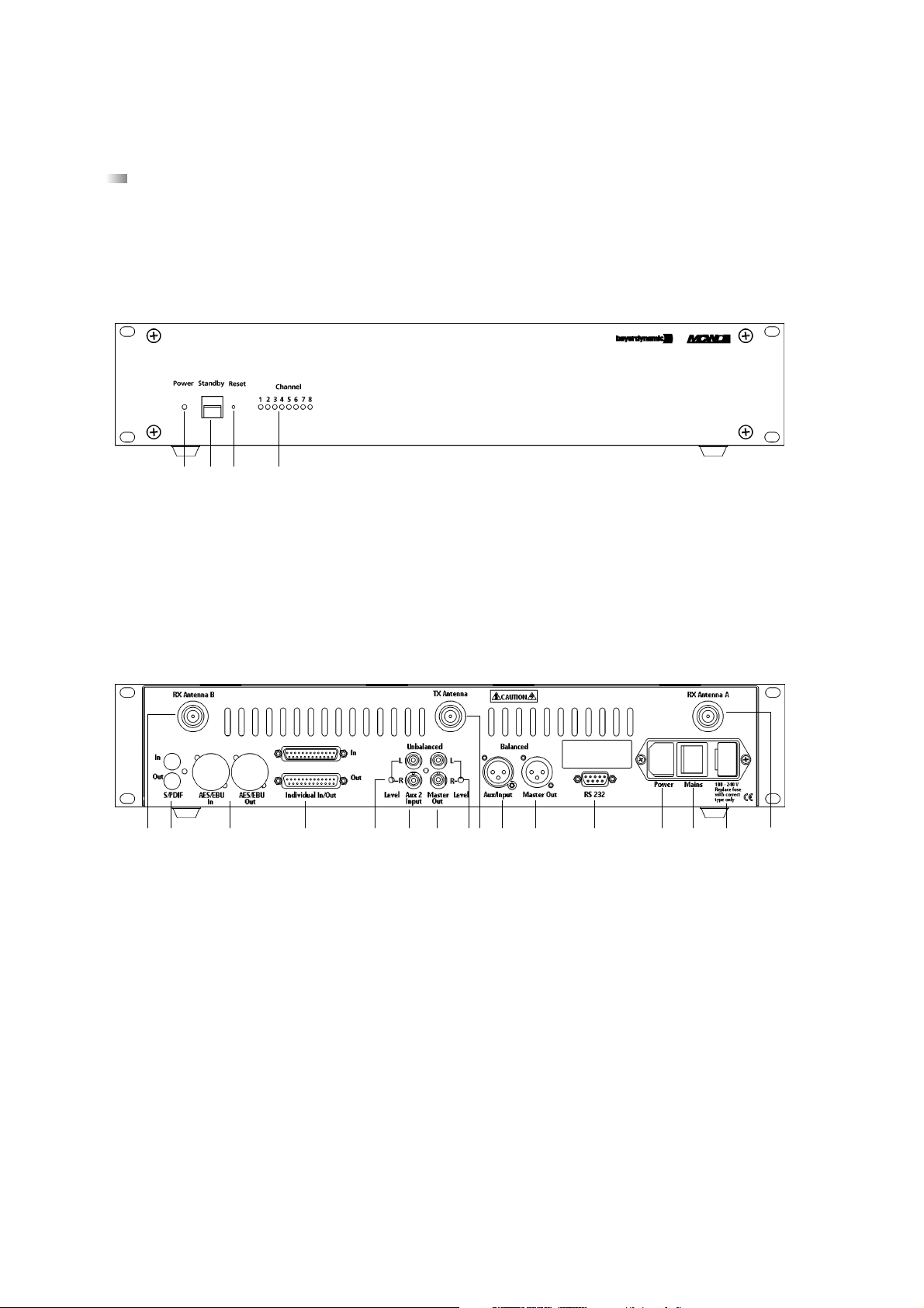
1.1 Controls and Indicators
Front view
(1) Power LED. LED is illuminated green when the unit is switched on.
(2) Standby button. When this button is pressed for more than 3 seconds all switched-on microphone units are switched off.
(3) Reset. This button resets the system into the switch-on state (to press the reset button use a paper clip).
(4) LEDs to indicate the status of the receiving channels. LED is illuminated green: the channel is vacant. LED is illuminated red:
the channel is occupied. Standard configuration: Channel 1 is used for data communication. Channel 2 to 7 for delegates,
channel 8 for the chairman.
Rear view
(5) Connection for receiving antenna A/B (N-connector)
(6) Fuse
(7) Mains supply
(8) On/Off-switch
(9) RS 232 port for the connection of PC or media control system
(10) Master Out, 3-pin XLR male, balanced, for the connection of external devices such as mixing consoles or sound contracting
system
(11) Aux 1 Input, 3-pin XLR female, balanced, for the connection of external sound sources or as Insert Return
(12) Connection for transmitting antenna (N-connector)
(13) Level control for Master Out, RCA
(14) Master Out, RCA, unbalanced, for the connection of external devices such as mixing consoles, sound contracting systems or
recorder (L + R)
(15) Aux 2 Input, RCA, unbalanced, for the connection of external devices such as CD-player (L + R)
(16) Level control for Aux 2 Input, RCA
As an option there are PCBs available for the connection of e.g. automatic mixers.
(17) (Analogue, individual input/output (2 x 25-pin Sub-D) for e.g. interpreting applications and for individual transmitting/receiving
signals)
(18) (Digital Input/Output, AES/EBU (XLR) and S/PDIF (RCA)).
(1) (2) (3) (4)
(5)(6)(7)(8)(9)(10)(11)(12)(13)(14)(15)(16)(17)(18)(18)(5)
Page 2

17
english
1.2 Setting up
1. Place the MCW-D 100 control unit in the same room as the transmitters.
2. Do not place the MCW-D 100 control unit near digitally controlled equipment.
3. Connect the receiving antennae to the antenna inputs A and B (5) using the appropriate adapter. For stand-alone-operation we
recommend using the CA 2411 angled rod antenna and the CA 2444 N(HF) Male - SMA Female adapter.
4. Connect the transmitting antenna to the antenna output (12). For stand-alone-operation we recommend using the CA 2411
angled rod antenna and the CA 2444 N(HF) Male - SMA Female adapter.
5. There must be an unobstructed path between the microphone units and the antennae. The range is around 50 m. For
optimum range the surface of the table is important, wood or plastic tables are ideal, but metal tables can cause interferences
and reduce the range.
6. Connect the XLR (10) or RCA (14) master output to the input of a mixing console/amplifier.
7. Connect the MCW-D 100 control unit to the mains (7). The internal power supply unit of the control unit can adjust automatically
between 110 V and 240 V.
8. Switch on the MCW-D 100 with the On/Off-switch (8) on the rear. The Power LED (1) on the front will illuminate green.
9. Depending on the configuration of the MCW-D 100 control unit 5 or more channel-LEDs will illuminate green (standard: 5 channels).
10. When mounting the MCW-D 100 control unit into a 19"-rack housing leave 1 HU for a ventilation panel.
Note
• If the system should fail to operate, i.e. the microphone unit is switched on but no sound is heard, press the reset button (3).
Should the system still fail to operate, please contact your beyerdynamic representative.
• If you press the standby button (2) for more than 3 seconds, you switch off all switched-on MCW-D microphone units within the range
of the MCW-D 100 control unit.
IMPORIMPOR
TT
ANT NOANT NO
IMPOR
IMPORIMPOR
T
TT
TETE
ANT NO
TE: To comply with FCC RF exposure compliance requirements, the following antenna installa-
ANT NOANT NO
TETE
tion and device-operating configuration must be satisfied. Only authorized and certified beyerdynamic systems
integrators may perform the installation of the antennas. There are no user serviceable parts or processes.
Connect the receiving antennae to the antenna inputs (5) A and B. Connect the transmitting antenna to the
antenna output (12). To maintain compliance with the FCC’s RF exposure guidelines, this transmitter and its
antenna must maintain a separation distance of least 20 centimeters from all persons.
Page 3
18
2. MCW-D 1021/1011 and MCW-D 1023/1013 Microphone Units
2.1 Controls and Indicators
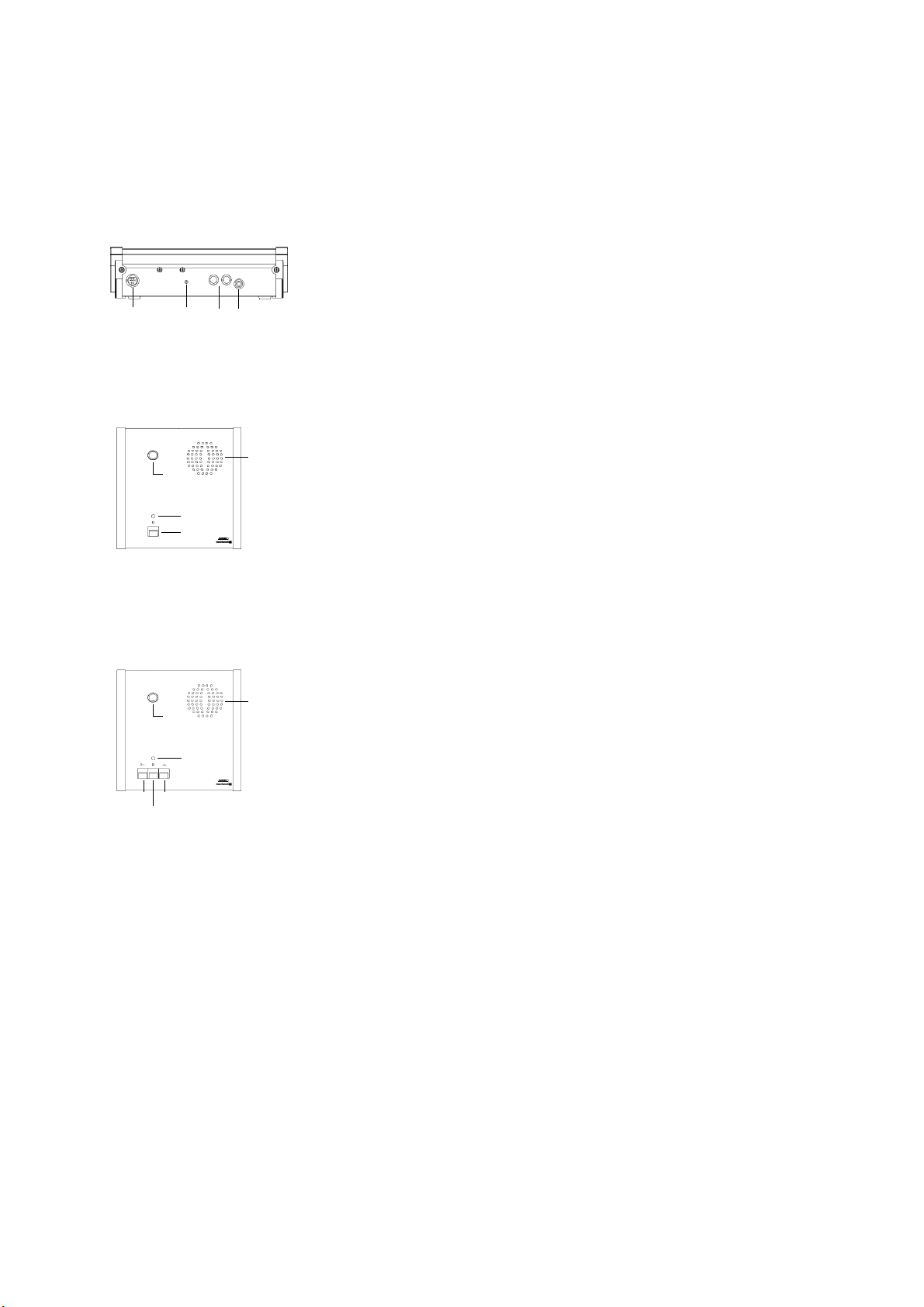
Rear view of MCW-D 1021/1011 Delegate and MCW-D 1023/1013 Chairman Microphone Unit
(1) Multi-function socket (connection of programming device, external
charger or DC-supply)
(2) Operating control LED
(3) Charging contacts for MCW-D 10, LE-D 10 charger
(4) Mini stereo jack (3.5 mm) for the connection of recorders or headphones
ATTENTION: This connection has been covered, because at present
special headphones can be connected only. If you need this
connection please contact beyerdynamic.
(5) Gooseneck microphone with illuminated ring
(6) Loudspeaker (MCW-D 1021 only)
(7) LED to indicate the function (green / red)
(8) Microphone button
(6)
(5)
(7)
(8)
(6)
(5)
(7)
(8)
(9)
(10)
Top View MCW-D 1021/1011 Delegate Microphone Unit
(5) Gooseneck microphone with illuminated ring
(6) Loudspeaker (MCW-D 1023 only)
(7) LED to indicate the function (green / red)
(8) Microphone button
(9) Clear button for clearing the delegate microphone units
(10) Function button for optional functions
Function button
Depending on the configuration the following functions are possible with
this button (10): mute, clear or priority. The function button can be configured
with a programming device connected to the chairman microphone unit or
remotely with the control unit. The MCW-D editor software can be used to
configure the button.
1. Mute
All delegate microphone units which were activated before, will be
muted when the chairman is speaking and will be re-activated when the
chairman switches off his microphone.
2. Clear
All delegate microphone units are cleared and cannot switch on their
microphone as long as the chairman is speaking.
3. Priority
All delegate microphone units will be cleared and the microphone of the
chairman unit will be switched on. The delegates can switch on their
microphones again.
4. Function
A command is sent via the RS 232 serial interface from the MCW-D 100
control unit and a programmed function is carried out via a media control system for instance (e.g. light control).
For the functions 1. - 3. there is also a command sent via the RS 232
serial interface from the MCW-D 100 control unit.
Top View MCW-D 1023/1013 Chairman Microphone Unit
(1) (2) (3) (4)
Page 4

19
english
2.2 Setting up
The microphone units have no separate on/off switch. They are switched on and off with the microphone button. By pressing
the button briefly, the microphone unit is switched on. The LED (7) flashes for a moment and the LED (2) on the rear is illuminated. By
pressing the button for more than 2 seconds the microphone unit is switched off and the LED (7) will illuminate twice red/green
briefly. Using the controller software (standby button) the microphone unit can be switched off via the control unit. Furthermore, the
microphone units are switched off automatically, when they do not receive a data signal from the control unit for more than one
minute.
Important:
If the microphone unit is out of range of the MCW-D 100 control unit the LED (7) will flash red. After one minute the microphone unit
will switch off automatically.
Switching on
Switch on the microphone unit by pressing the microphone button briefly. The green operating control LED (2) on the rear will
illuminate.
The microphone units have an integrated rechargeable battery allowing an operating time of at least 10 hours in conference mode.
As soon as the capacity is too low for satisfactory operation, the operating control LED (2) will flash. The remaining time of
operation is around 30 minutes. The decreasing battery voltage is also signaled by the MCW-D 100 control unit at the RS 232 socket
and can be evaluated by an external media control system.
Manual Mode
Press the microphone button (8) to switch the gooseneck microphone on or off.
The LED (7) is illuminated green: The integrated transmitter is adjusted to a free frequency and switched on.
Red ring of the gooseneck
microphone is illuminated: The microphone is ready for talking.
Using the standard version of the MCW-D 100 control unit 3 delegates and 1 chairman can speak simultaneously. Using
additional PCBs inside the MCW-D 100 up to 6 delegates and 1 chairman can speak simultaneously.
Important:
If the number of open microphones is reached, a microphone can only be switched on manually when another
microphone unit has been switched off.
Request-To-Talk Mode
The mode is only possible in conjunction with a PC using the MCW-D Controller software or media control system (AMX/Panja®,
Crestron®etc.). The request-to-talk is registered in the system by pressing the microphone button of the microphone unit. The allocation is made by the operator at the PC or touchscreen of the media control system. The LED (7) is illuminated to indicate the requestto-talk. If you press the microphone button again the request-to-talk is cleared. The LED (7) goes out.
2.3 Auto-Off-Function
The delegate microphone units have a power saving auto-off function, i.e. if no-one speaks into the microphone for more than
20 seconds, the microphone unit switches off automatically. The auto-off-function has been deactivated at the factory. The response
threshold and the time after which the microphone switches off can be adjusted with a programming device or PC using the Editor
software. The illuminated ring of the gooseneck microphone will flash 5 seconds before the microphone unit is switched off.
2.4 Addressing the Microphone Units / Serial Number
At the factory each microphone unit is programmed with a different identity number so that the MCW-D 100 control unit can
control them individually. This number is printed on the bottom.
When you subsequently order more microphone units later, please inform the supplier of your current identitiy numbers to avoid
duplication.
Page 5

20
2.5 Documentation Output
A headphone (e.g. DT 301) can be connected to the documentation output (4). We recommend a min. impedance of 200 Ω.
ATTENTION: This connection has been covered, because at present special headphones can be connected only. If you need
this connection please contact beyerdynamic.
2.6 CA 2455 External Power Supply
The MCW-D microphone units can be powered with the CA 2455 external power supply unit which can be connected to the
multi-function socket (1). The DC-voltage should be 18 V DC (±0.5 V), current max. 180 mA, residual hum < 20 mV.
Important:
Connect and disconnect the external power supply only when the microphone unit is switched off.
If the microphone unit is powered by the DC-power supply first and when the power supply is switched off, the microphone unit will be
powered by the integrated battery until it is nearly empty. The microphone unit switches off automatically to avoid an exhaustive
discharge.
But if the switched on microphone unit is powered by the battery first and then connected to DC-power, the external power supply will
power the microphone unit.
2.7 Maintenance of the MCW-D Microphone Units
For cleaning the MCW-D microphone units when they are slightly dirty (finger prints, dust, jam or juice) use a soft, damp cloth,
sponge or brush and a liquid cleaning agent. Before cleaning the surface it must be moistened thoroughly. Afterwards it must be
cleaned with clear water. Make sure not to allow any water to enter the unit. For dirt caused by mineral oils and fats, animal and
vegetable fats use spirit, isopropyl alcohol or benzine.
For dirt caused by ballpoint pens, typewriter ribbons or carbon paper use isopropyl alcohol or spirit.
Clean the supplied pop shield with clear water. Make sure that it is completely dry before you put it on the microphone again.
2.8 Safety Code
Using the MCW-D Editor software or the MCW-D 1003 programming device a safety code can be entered for the MCW-D micro-
phone units and the MCW-D 100 control unit within one system. This will increase the safety against unauthorised listening. For a
detailed description please refer to the appropriate manuals.
Page 6

21
english
Drawing 2
at the top RX
at the bottom TX
Drawing 1
Page 7

22
4. MCW-D 10 Charging Unit
With the integrated LE-D 10 charger in the MCW-D 10 transport case, it is possible to charge up to 10 microphone unit batteries.
The battery state is indicated on the outside of the case.
The MCW-D 10 transport case can be extended with more LE-D 10 chargers for 10 microphone units each.
4.1 Charging Process
1. Connect the charger to AC power and switch it on. The LED on the switch will illuminate.
2. Put the switched-off microphone units into the charging compartments. If microphone units are switched on, they are switched
off automatically. When the microphone units are used again, they must be switched on.
3. The charging process is indicated by the green LEDs on the outside.
a) ___ ___ ___ __ LED is flashing slowly: Battery is charged
b) _________________ LED illuminates permanently: Battery is full
c) - - - - - - - - - - - - - - LED is flashing very rapidly: Error
d) LED is off: No microphone unit is inserted into charging compartment or
has no contact
e) . . . . . . . . LED flashes rapidly: Forming mode
f) . - . - . - . - . - . - . - . LED long flash/short flash: Charging in the forming mode
Note
If an error has occured, try to start the charging process once again. If the LEDs are still flashing rapidly, please contact your
beyerdynamic dealer.
4.2 Forming Mode
The LE-D 10 charging units are equipped with a forming mode for the rechargeable batteries inside the microphone units. The
batteries are formed and charged at the factory. If you have not used the microphone units for several months, you should form the
batteries before you set up the microphone units. Do this as described in the following:
• First of all remove all microphone units from the charging compartments.
• After switching on the charger press the buttons in the bottom of the two furthest charging compartments (next to the contact
pins in the round gap).
• Pressing one of these buttons will activate the forming mode for 5 charging compartments. The LEDs will flash rapidly.
• Then put the microphone units into the charging compartments. The LEDs will flash short and long.
• When the green LEDs are permanently on, then the battery is full.
Caution:
Only form empty or partly discharged batteries, but never full batteries!
Do not switch off the charging unit during the forming mode, as this will interrupt the forming mode.
The forming mode will be terminated automatically when the microphone units are fully charged or when the charger is switched
off.
5. Battery Charging with external Charger
The MCW-D microphone units can be also charged with the CA 2456 external charger which is connected to the multi-function
socket (1).
Important:
The automatic switching off of the microphone units when they are charged is not possible with the CA 2456. Therefore, the
microphone units must be switched off manually (or via the MCW-D 100 control unit) before charging.
Page 8

23
english
7. Accessories
Supplied Accessories
1 mains cable
Note:
The supply does not include any antennae.
Optional Accessories
CA 2411 Angled rod antenna, 2.4 GHz, N-connection . . . . . . . . . . . . . . . . . . . . . . . . . . . . . . . . . . . . . Order # 464.236
CA 2442 Adapter N(HF) Female - SMA Male. . . . . . . . . . . . . . . . . . . . . . . . . . . . . . . . . . . . . . . . . . . . . Order # 464.376
CA 2443 Adapter N(HF) Female - SMA Female . . . . . . . . . . . . . . . . . . . . . . . . . . . . . . . . . . . . . . . . . . . Order # 464.384
CA 2444 Adapter N(HF) Male - SMA Female. . . . . . . . . . . . . . . . . . . . . . . . . . . . . . . . . . . . . . . . . . . . . Order # 464.392
CA 2445 Adapter N(HF) Male - SMA Male . . . . . . . . . . . . . . . . . . . . . . . . . . . . . . . . . . . . . . . . . . . . . . Order # 465.151
CA 2446 Remote power supply adapter . . . . . . . . . . . . . . . . . . . . . . . . . . . . . . . . . . . . . . . . . . . . . . . . Order # 465.178
CA 2450 PCB 1 transmitting/1 receiving channel, 2.4 GHz DSSS . . . . . . . . . . . . . . . . . . . . . . . . . . . . . . Order # 464.899
CA 2451 PCB Individual In/Out . . . . . . . . . . . . . . . . . . . . . . . . . . . . . . . . . . . . . . . . . . . . . . . . . . . . . . . Order # 464.406
CA 2455 Power supply unit with multi-pin plug . . . . . . . . . . . . . . . . . . . . . . . . . . . . . . . . . . . . . . . . . . Order # 465.216
CA 2456 Single charging unit . . . . . . . . . . . . . . . . . . . . . . . . . . . . . . . . . . . . . . . . . . . . . . . . . . . . . . . . Order # 465.569
8. Technical Specifications
General
Frequency range. . . . . . . . . . . . . . . . . . . . . . . . . . . . . 2400 - 2483,5 MHz (ISM-band)
Modulation. . . . . . . . . . . . . . . . . . . . . . . . . . . . . . . . . Direct Sequence Spread Spectrum DSSS, digital signal processing acc.
to own standard
Max. number of channels. . . . . . . . . . . . . . . . . . . . . . 2*8 useable duplex channels per system
Signal-to-noise ratio . . . . . . . . . . . . . . . . . . . . . . . . . . 80 dB typ., (unweighted signal-to-noise ratio)
Range between microphone units
and control unit . . . . . . . . . . . . . . . . . . . . . . . . . . . . . > 100 m
Power supply . . . . . . . . . . . . . . . . . . . . . . . . . . . . . . . 110 - 240 VAC 50/60 Hz
Approval. . . . . . . . . . . . . . . . . . . . . . . . . . . . . . . . . . . world-wide
6. Components
MCW-D 1021 Delegate microphone unit with loudspeaker . . . . . . . . . . . . . . . . . . . . . . . . . . . . . . . . . . . . . Order # 459.119
MCW-D 1023 Chairman microphone unit with loudspeaker . . . . . . . . . . . . . . . . . . . . . . . . . . . . . . . . . . . . Order # 459.127
MCW-D 1011 Delegate microphone unit without loudspeaker . . . . . . . . . . . . . . . . . . . . . . . . . . . . . . . . . . Order # 459.135
MCW-D 1013 Chairman microphone unit without loudspeaker. . . . . . . . . . . . . . . . . . . . . . . . . . . . . . . . . . Order # 459.143
MCW-D 100 Control unit. . . . . . . . . . . . . . . . . . . . . . . . . . . . . . . . . . . . . . . . . . . . . . . . . . . . . . . . . . . . . . . Order # 495.151
MCW-D 1003 Programming device . . . . . . . . . . . . . . . . . . . . . . . . . . . . . . . . . . . . . . . . . . . . . . . . . . . . . . . . Order # 465.402
MCW-D 10 Charging and transport case for 10 microphone units . . . . . . . . . . . . . . . . . . . . . . . . . . . . . . Order # 462.691
LA 10 Empty compartment for MCW-D 10 . . . . . . . . . . . . . . . . . . . . . . . . . . . . . . . . . . . . . . . . . . . . Order # 458.708
LB 10 Bottom for MCW-D 10 with trolley wheels. . . . . . . . . . . . . . . . . . . . . . . . . . . . . . . . . . . . . . . Order # 458.716
LD 10 Cover for MCW 10. . . . . . . . . . . . . . . . . . . . . . . . . . . . . . . . . . . . . . . . . . . . . . . . . . . . . . . . . . Order # 458.686
LE-D 10 Charging unit for MCW-D 10 . . . . . . . . . . . . . . . . . . . . . . . . . . . . . . . . . . . . . . . . . . . . . . . . . Order # 462.683
Page 9

24
Microphone Units
Transmitter power . . . . . . . . . . . . . . . . . . . . . . . . . . . < 20 mW per channel (13 dBm)
Connection . . . . . . . . . . . . . . . . . . . . . . . . . . . . . . . . . Multi-port connection, type mini DIN
Pin 1 = Ground (ICP)
Pin 2 = +VDD (ICP)
Pin 3 = +VPP (ICP)
Pin 4 = RB6 (ICP)
Pin 5 = RB7 (ICP)
Pin 6 = RC3 / SDL (I2C)
Pin 7 = RC4 / SDA (I2C)
Pin 8 = +Battery (parallel to the charging contacts)
Pin 9 = +Supply (max. 180 mA)
Housing = Ground
Battery voltage. . . . . . . . . . . . . . . . . . . . . . . . . . . . . . 12 NiMH cells, 1600 mAh
Current consumption . . . . . . . . . . . . . . . . . . . . . . . . . 150 - 180 mA (depending on the operating status)
External DC operation . . . . . . . . . . . . . . . . . . . . . . . . 18 V DC (±0.5 V), residual hum < 20 mV, 180 mA (at 18 V)
Loudspeaker . . . . . . . . . . . . . . . . . . . . . . . . . . . . . . . . Wide-band, integrated loudspeaker
Volume decrease when Mic On . . . . . . . . . . . . . . . . . adjustable, set to decrease 20 dB at the factory
AF output . . . . . . . . . . . . . . . . . . . . . . . . . . . . . . . . . . Documentation output, adjustable, unbalanced jack socket (3.5 mm, stereo)
Connection . . . . . . . . . . . . . . . . . . . . . . . . . . . . . . . . . Tip = AF+
Ring = AF -
Shield = not connected
Output level . . . . . . . . . . . . . . . . . . . . . . . . . . . . . . . . max. 500 mV rms
Min. impedance . . . . . . . . . . . . . . . . . . . . . . . . . . . . . 200 Ω
Integrated limiter against talkover . . . . . . . . . . . . . . cannot be switched off
Limiter activity . . . . . . . . . . . . . . . . . . . . . . . . . . . . . . from 106 dB SPL
Microphone sensitivity . . . . . . . . . . . . . . . . . . . . . . . . 300 mV/Pa (measured at XLR-output of MCW-D 100) ±2 dB (1 kHz)
Max. SPL . . . . . . . . . . . . . . . . . . . . . . . . . . . . . . . . . . . > 120 dB SPL
Power supply . . . . . . . . . . . . . . . . . . . . . . . . . . . . . . . 14.4 V with integrated NiMH battery (12 cells)
Battery capacity . . . . . . . . . . . . . . . . . . . . . . . . . . . . . 1600 mAh
Operating time. . . . . . . . . . . . . . . . . . . . . . . . . . . . . . 8 hours in talking mode, 10 hours in “receiving mode”
Temperature range. . . . . . . . . . . . . . . . . . . . . . . . . . . +10° - 40°C (at < 90% humidity)
Storage temperature . . . . . . . . . . . . . . . . . . . . . . . . . -20° - 55°C (at < 90% humidity)
Dimensions (without microphone). . . . . . . . . . . . . . . Length: 190 mm
Width: 180 mm
Height front: 15 mm
Height rear: 52 mm
MCW-D 100 Control Unit
Frequency response . . . . . . . . . . . . . . . . . . . . . . . . . . 60 Hz - 10 kHz (-3 dB)
Operation mode. . . . . . . . . . . . . . . . . . . . . . . . . . . . . Diversity (receiver), separate for each channel
Antenna connection. . . . . . . . . . . . . . . . . . . . . . . . . . 3 N-connectors (female)
Transmitting power . . . . . . . . . . . . . . . . . . . . . . . . . . < 40 mW per channel (16 dBm)
Connections
Serial control port . . . . . . . . . . . . . . . . . . . . . . . . . . . RS 232, standard with 9.6 kbps, 8N1
Master output balanced. . . . . . . . . . . . . . . . . . . . . . . XLR, +6 dBu
Master output unbalanced. . . . . . . . . . . . . . . . . . . . . RCA, level adjustable (1.55 V - 300 mV range)
Input balanced . . . . . . . . . . . . . . . . . . . . . . . . . . . . . . XLR, +6 dBu
Input unbalanced . . . . . . . . . . . . . . . . . . . . . . . . . . . . RCA, level adjustable (min. 500 mV for max. level)
Integrated limiter to avoid clipping of the input signals
Number of the channels. . . . . . . . . . . . . . . . . . . . . . . max. 7 channels can be used for microphoneunits
Extensions. . . . . . . . . . . . . . . . . . . . . . . . . . . . . . . . . . CA 2450, PCB for additional transmitting/receiving channel
CA 2451, balanced inputs and outputs (each +6dBu nominal level)
with 25-pin Sub-plug (female)
corresponding to standard «TASCAM DA Multitrack-Recorder»
AF
ATTENTION:
This AF output has been covered, because
at present special headphones can be
connected only. If you need this connection
please contact beyerdynamic.
789
3456
12
Page 10

25
english
Power supply . . . . . . . . . . . . . . . . . . . . . . . . . . . . . . . 110 - 240 V AC 50/60 Hz
Fuse . . . . . . . . . . . . . . . . . . . . . . . . . . . . . . . . . . . . . . 3.15 A slow-blow
Power consumption . . . . . . . . . . . . . . . . . . . . . . . . . . < 70 V A
Temperature range. . . . . . . . . . . . . . . . . . . . . . . . . . . +10° - 50°C (at < 90% humidity)
Indication . . . . . . . . . . . . . . . . . . . . . . . . . . . . . . . . . . 8 channel LEDs (red/green) and Power LED
Depth of Rack. . . . . . . . . . . . . . . . . . . . . . . . . . . . . . . 380 mm at least
Dimensions (W x H x D) . . . . . . . . . . . . . . . . . . . . . . . 19", 2HU (440 x 88 x 310 mm)
MCW-D 10 / LE-D 10 Charger
Max. charging current . . . . . . . . . . . . . . . . . . . . . . . . 1 A
Power supply . . . . . . . . . . . . . . . . . . . . . . . . . . . . . . . 115 V AC / 230 V AC, 50 / 60 Hz
Charging principle . . . . . . . . . . . . . . . . . . . . . . . . . . . software controlled charging curve, variable impulse charging,
re-charging after 72 hrs.
Rechargeable battery . . . . . . . . . . . . . . . . . . . . . . . . . NiMH, 12 cells
Switching-off . . . . . . . . . . . . . . . . . . . . . . . . . . . . . . . ∆ U-recognition and safety timer
Fuse at the mains socket . . . . . . . . . . . . . . . . . . . . . . 6.3 A slow-blow fuse
Max. ambient temperature . . . . . . . . . . . . . . . . . . . . 40°C when charging (< 90% atmospheric humidity)
Storage temperature . . . . . . . . . . . . . . . . . . . . . . . . . -20° - 55°C
Ventilator . . . . . . . . . . . . . . . . . . . . . . . . . . . . . . . . . . switched on automatically
Charging unit . . . . . . . . . . . . . . . . . . . . . . . . . . . . . . . 10 microphone units
Charging time. . . . . . . . . . . . . . . . . . . . . . . . . . . . . . . max. 2 hours when the battery is completely empty (1600 mAh)
Min. charging time in the “forming” mode . . . . . . . 30 minutes
LED-indication when battery is charged:
a) ___ ___ ___ __ LED is flashing slowly: . . . . . . . Battery is charged
b) _________________ LED illuminates permanently: . Battery is full
c) - - - - - - - - - - - - - - LED is flashing very rapidly: . . . Error
d) LED is off: . . . . . . . . . . . . . . . . . . . . . . . . . . . . . . . . No microphone unit is inserted into charging compartment or has no contact
e) . . . . . . . . LED flashes rapidly: . . . . . . . . . Forming mode
f) . - . - . - . - . - . - . - . LED long flash/short flash:. . . . Charging in the forming mode
Dimensions (L x W x H). . . . . . . . . . . . . . . . . . . . . . . . 657 x 370 x 451 mm
CA 2451 PCB Individual In/Out
8 inputs. . . . . . . . . . . . . . . . . . . . . . . . . . . . . . . . . . . . 25-pin Sub-D (female) corresponding to connection of TASCAM-DA recorder
Frequency response . . . . . . . . . . . . . . . . . . . . . . . . . . 60 Hz - 10 kHz (-3 dB)
8 outputs . . . . . . . . . . . . . . . . . . . . . . . . . . . . . . . . . . 25-pin Sub-D (female) corresponding to connection of TASCAM-DA recorder
Frequency response . . . . . . . . . . . . . . . . . . . . . . . . . . 60 Hz - 10 kHz (-3 dB)
Output level . . . . . . . . . . . . . . . . . . . . . . . . . . . . . . . . +6 dBu for max. level
Input level . . . . . . . . . . . . . . . . . . . . . . . . . . . . . . . . . +6 dBu for max. level (without limiter)
Connection:
CA 2455 DC Power Supply Unit
Voltage. . . . . . . . . . . . . . . . . . . . . . . . . . . . . . . . . . . . 18 V (± 0.5 V) DC
Current consumption . . . . . . . . . . . . . . . . . . . . . . . . . max. 333 mA
Input voltage . . . . . . . . . . . . . . . . . . . . . . . . . . . . . . . 110 - 240 V AC 50/60 Hz
Plug . . . . . . . . . . . . . . . . . . . . . . . . . . . . . . . . . . . . . . Euro plug, other plugs upon request
Page 11

26
FCC ID: OSDMCWD200
FCC ID: OSDMCWDTUA
This device complies with Part 15 of the FCC Rules. Operation is subject to the following two conditions: (1) This device may not cause
harmful interference, and (2) This device must accept any interference received, including interference that may cause undesired
operation.
In accordance with FCC requirements, changes or modifications not expressly approved by beyerdynamic GmbH could void the user’s
authority to operate this product. Any changes or modifications not expressly approved by the party responsible for compliance could
void the user’s authority to operate this equipment.
CA 2456 Single charging unit
Type . . . . . . . . . . . . . . . . . . . . . . . . . . . . . . . . . . . . . . Ansmann ACS 410 Traveller spezial
Input voltage . . . . . . . . . . . . . . . . . . . . . . . . . . . . . . . 100 - 240 V AC 50/60 Hz, adapter for Europe, UK, USA and Australia
Charging current . . . . . . . . . . . . . . . . . . . . . . . . . . . . max. 650 mA (initial charging with approx. 80 mA)
Charging control . . . . . . . . . . . . . . . . . . . . . . . . . . . . ∆ U-recognition and safety timer
Additional function . . . . . . . . . . . . . . . . . . . . . . . . . . Pre-discharge via button
Indications . . . . . . . . . . . . . . . . . . . . . . . . . . . . . . . . . red LED to indicate charging status
green LED to indicate charged / trickle charge status
red flashing LED indicates wrong polarity and defective battery
Page 12

EC-DECLARATION
OF
CONFORMITY
Application of
Council directive: 89/336/EEC, 93/68/EEC
Electromagnetic Compatibility
99/5/EEC
R&TTE Directive
Standards to which
Conformity is Declared: EN 60268 (former DIN IEC 268)
ETS 300 440
ETS 300 826
Manufacturer’s Name: beyerdynamic GmbH & Co.
Manufacturer’s Address: Theresienstraße 8, 74072 Heilbronn, Germany
Type of Equipment: Wireless Conference System
MCW Digital
Model Numbers: MCW D 1011, MCW D 1013,
MCW D 1021, MCW D 1023
MCW D 100
I, the undersigned, as an employee of beyerdynamic, hereby declare that the equipment
specified conforms to the above Directive and Standards.
Date: 1
st
November, 2001
Full Name: Ulrich Roth
Position: R&D Manager
 Loading...