

Beyerdynamic MCW-D 2011, MCW-D 2021, MCW-D 2071, MCW-D 2013, MCW-D 2023 Operating Instructions Manual
...Page 1
BEDIENUNGSANLEITUNG
OPERATING INSTRUCTIONS
NOTICE D’UTILISATION
Digitales, drahtloses Diskussionssystem
Digital, wireless Discussion System
Système de conférence digital sans fil
200
Page 2

Page 3

3
Sicherheitsinformationen . . . . . . . . . . . . . . . . . . . . . . . . . . . . . . . . . . . . . . . . . . . . . . . . . . . . . . . . . . . . Seite 4
1. Steuerzentrale MCW-D 200 . . . . . . . . . . . . . . . . . . . . . . . . . . . . . . . . . . . . . . . . . . . . . . . . . . . . . . Seite 4
1.1 Bedien- und Kontrollelemente . . . . . . . . . . . . . . . . . . . . . . . . . . . . . . . . . . . . . . . . . . . . . Seite 4
1.2 Inbetriebnahme . . . . . . . . . . . . . . . . . . . . . . . . . . . . . . . . . . . . . . . . . . . . . . . . . . . . . . . . . Seite 5
1.2.1 Aufstellen der Steuerzentrale. . . . . . . . . . . . . . . . . . . . . . . . . . . . . . . . . . . . . . . . . Seite 5
1.2.2 Antennen anschließen . . . . . . . . . . . . . . . . . . . . . . . . . . . . . . . . . . . . . . . . . . . . . . Seite 5
1.2.3 Audioanschluss . . . . . . . . . . . . . . . . . . . . . . . . . . . . . . . . . . . . . . . . . . . . . . . . . . . . Seite 6
1.2.4 Netzanschluss . . . . . . . . . . . . . . . . . . . . . . . . . . . . . . . . . . . . . . . . . . . . . . . . . . . . . Seite 6
1.2.5 Ein-/Ausschalten . . . . . . . . . . . . . . . . . . . . . . . . . . . . . . . . . . . . . . . . . . . . . . . . . . . Seite 6
1.2.6 Kanal-Anzeige. . . . . . . . . . . . . . . . . . . . . . . . . . . . . . . . . . . . . . . . . . . . . . . . . . . . . Seite 7
1.2.7 Rackmontage . . . . . . . . . . . . . . . . . . . . . . . . . . . . . . . . . . . . . . . . . . . . . . . . . . . . . Seite 7
1.2.8 Gleichzeitiger Betrieb von Mediensteuersystem und PC . . . . . . . . . . . . . . . . . . . . Seite 7
1.3 Anschließen abgesetzter Antennen . . . . . . . . . . . . . . . . . . . . . . . . . . . . . . . . . . . . . . . . . Seite 8
1.4 Fernspeisung der Antennensignalverstärker über Zentrale . . . . . . . . . . . . . . . . . . . . . . . Seite 9
2. Optionaler Einbau von Nachrüstplatinen für weitere Funktionen. . . . . . . . . . . . . . . . . . . . . . . . . Seite 10
2.1 Zusätzliche Sende-/Empfangskanäle . . . . . . . . . . . . . . . . . . . . . . . . . . . . . . . . . . . . . . . . . Seite 10
2.2 Fremdsprachige Konferenzen / Dolmetschanwendungen. . . . . . . . . . . . . . . . . . . . . . . . . Seite 13
2.3 Digitale Ein- und Ausgänge AES/EBU und S-PDIF . . . . . . . . . . . . . . . . . . . . . . . . . . . . . . . Seite 13
3. Delegierten- und Präsidentensprechstellen . . . . . . . . . . . . . . . . . . . . . . . . . . . . . . . . . . . . . . . . . . Seite 14
3.1 Sprechstellen MCW-D 2011/2013 und MCW-D 2021/2023 . . . . . . . . . . . . . . . . . . . . . . . . . Seite 14
3.1.1 Bedien- und Kontrollelemente . . . . . . . . . . . . . . . . . . . . . . . . . . . . . . . . . . . . . . . . Seite 14
3.1.2 Ein-/Ausschalten . . . . . . . . . . . . . . . . . . . . . . . . . . . . . . . . . . . . . . . . . . . . . . . . . . . Seite 15
3.1.3 DC-gespeiste Versionen MCW-D 2021 DC und MCW-D 2023 DC . . . . . . . . . . . . . . Seite 15
3.2 Sprechstellen MCW-D 2071 und 2073 mit Display. . . . . . . . . . . . . . . . . . . . . . . . . . . . . . . Seite 16
3.2.1 Bedien- und Kontrollelemente . . . . . . . . . . . . . . . . . . . . . . . . . . . . . . . . . . . . . . . . Seite 16
3.2.2 Ein-/Ausschalten . . . . . . . . . . . . . . . . . . . . . . . . . . . . . . . . . . . . . . . . . . . . . . . . . . . Seite 17
3.2.3 DC-gespeiste Versionen MCW-D 2071 DC und MCW-D 2073 DC . . . . . . . . . . . . . . Seite 17
3.2.4 Einstellbare Funktionen MCW-D 2071 und MCW-D 2073. . . . . . . . . . . . . . . . . . . . Seite 18
3.3 Systemanschlusseinheit MCW-D 2673 . . . . . . . . . . . . . . . . . . . . . . . . . . . . . . . . . . . . . . . . Seite 20
3.3.1 Anschlüsse. . . . . . . . . . . . . . . . . . . . . . . . . . . . . . . . . . . . . . . . . . . . . . . . . . . . . . . . Seite 20
3.3.2 Installation . . . . . . . . . . . . . . . . . . . . . . . . . . . . . . . . . . . . . . . . . . . . . . . . . . . . . . . Seite 20
3.3.3 Ein-/Ausschalten . . . . . . . . . . . . . . . . . . . . . . . . . . . . . . . . . . . . . . . . . . . . . . . . . . . Seite 20
3.3.4 Systemanschlusseinheit mit Display . . . . . . . . . . . . . . . . . . . . . . . . . . . . . . . . . . . . Seite 20
3.4 Speisung/Betriebszeit. . . . . . . . . . . . . . . . . . . . . . . . . . . . . . . . . . . . . . . . . . . . . . . . . . . . . Seite 21
3.5 Speisung über externes Netzteil CA 2455 . . . . . . . . . . . . . . . . . . . . . . . . . . . . . . . . . . . . . Seite 21
3.6 Speisung MCW-D 2673. . . . . . . . . . . . . . . . . . . . . . . . . . . . . . . . . . . . . . . . . . . . . . . . . . . . Seite 21
3.7 Betriebsart Manuell . . . . . . . . . . . . . . . . . . . . . . . . . . . . . . . . . . . . . . . . . . . . . . . . . . . . . . Seite 22
3.8 Anmeldebetrieb ohne externen PC oder Steuerung . . . . . . . . . . . . . . . . . . . . . . . . . . . . . Seite 22
3.9 Aufzeichnen der Konferenz . . . . . . . . . . . . . . . . . . . . . . . . . . . . . . . . . . . . . . . . . . . . . . . Seite 23
3.10 Pflege der MCW-D Sprechstellen. . . . . . . . . . . . . . . . . . . . . . . . . . . . . . . . . . . . . . . . . . . . Seite 23
4. Programmierbare Sprechstellenfunktionen mit MCW-D 200 Editor Software. . . . . . . . . . . . . . . . Seite 24
4.1 Sicherheitscode . . . . . . . . . . . . . . . . . . . . . . . . . . . . . . . . . . . . . . . . . . . . . . . . . . . . . . . . . Seite 24
4.2 Auto-Off-Funktion. . . . . . . . . . . . . . . . . . . . . . . . . . . . . . . . . . . . . . . . . . . . . . . . . . . . . . . Seite 24
4.3 Programmierbare Funktionstaste Präsident . . . . . . . . . . . . . . . . . . . . . . . . . . . . . . . . . . . Seite 24
4.4 Abstimmung . . . . . . . . . . . . . . . . . . . . . . . . . . . . . . . . . . . . . . . . . . . . . . . . . . . . . . . . . . . Seite 25
4.5 Override-Betrieb . . . . . . . . . . . . . . . . . . . . . . . . . . . . . . . . . . . . . . . . . . . . . . . . . . . . . . . . Seite 25
4.6 Push-To-Talk-Betrieb . . . . . . . . . . . . . . . . . . . . . . . . . . . . . . . . . . . . . . . . . . . . . . . . . . . . . Seite 25
4.7 Automatik-Betrieb. . . . . . . . . . . . . . . . . . . . . . . . . . . . . . . . . . . . . . . . . . . . . . . . . . . . . . . Seite 25
4.8 Betriebsart Anmeldung . . . . . . . . . . . . . . . . . . . . . . . . . . . . . . . . . . . . . . . . . . . . . . . . . . . Seite 26
4.9 Zoning-Funktion . . . . . . . . . . . . . . . . . . . . . . . . . . . . . . . . . . . . . . . . . . . . . . . . . . . . . . . . Seite 26
4.10 Empfangen von Nachrichten . . . . . . . . . . . . . . . . . . . . . . . . . . . . . . . . . . . . . . . . . . . . . . . Seite 26
5. Ladegerät LE-D 10 im Koffer MCW-D 10 . . . . . . . . . . . . . . . . . . . . . . . . . . . . . . . . . . . . . . . . . . . . Seite 27
5.1 Erstinbetriebnahme . . . . . . . . . . . . . . . . . . . . . . . . . . . . . . . . . . . . . . . . . . . . . . . . . . . . . . Seite 27
5.2 Ladevorgang . . . . . . . . . . . . . . . . . . . . . . . . . . . . . . . . . . . . . . . . . . . . . . . . . . . . . . . . . . . Seite 27
5.3 Formierung . . . . . . . . . . . . . . . . . . . . . . . . . . . . . . . . . . . . . . . . . . . . . . . . . . . . . . . . . . . . Seite 28
6. Akkuladung über externes Ladegerät CA 2456 . . . . . . . . . . . . . . . . . . . . . . . . . . . . . . . . . . . . . . . Seite 28
7. Problemlösung . . . . . . . . . . . . . . . . . . . . . . . . . . . . . . . . . . . . . . . . . . . . . . . . . . . . . . . . . . . . . . . . Seite 29
8. Komponenten. . . . . . . . . . . . . . . . . . . . . . . . . . . . . . . . . . . . . . . . . . . . . . . . . . . . . . . . . . . . . . . . . Seite 30
9. Zubehör . . . . . . . . . . . . . . . . . . . . . . . . . . . . . . . . . . . . . . . . . . . . . . . . . . . . . . . . . . . . . . . . . . . . . Seite 30
10. Technische Daten . . . . . . . . . . . . . . . . . . . . . . . . . . . . . . . . . . . . . . . . . . . . . . . . . . . . . . . . . . . . . . Seite 32
11. Blockschaltbild Audio-Signalfluß . . . . . . . . . . . . . . . . . . . . . . . . . . . . . . . . . . . . . . . . . . . . . . . . . . Seite 37
Konformitätserklärung . . . . . . . . . . . . . . . . . . . . . . . . . . . . . . . . . . . . . . . . . . . . . . . . . . . . . . . . . . . . . . Seite 110
INHALT
deutsch
Page 4
4
BEDIENUNGSANLEITUNG MCW-D 200
Sie haben sich für das drahtlose, digitale Konferenzsystem MCW-D 200 von beyerdynamic entschieden. Wir danken für Ihr
Vertrauen. Nehmen Sie sich bitte einige Minuten Zeit und lesen Sie diese Bedienungsanleitung vor Inbetriebnahme aufmerksam
durch.
In dieser Bedienungsanleitung werden die Installation und Bedienung des Systems ohne Steuerung und Konfiguration über einen
PC beschrieben.
Folgende Komponenten gehören zur Grundausstattung eines Systems für den Betrieb ohne PC:
• Steuerzentrale MCW-D 200
• Delegiertensprechstelle MCW-D 2011, 2021 oder 2071
• Präsidentensprechstelle MCW-D 2013, 2023 oder 2073
• Systemanschlusseinheit MCW-D 2673
Weitere Informationen zur Steuerung und Konfiguration des MCW-D 200 Systems über einen PC finden Sie in der Bedienungsanleitung MCW-D 200 Editor.
1. Steuerzentrale MCW-D 200
Die Steuerzentrale MCW-D 200 ist das Herzstück des Systems. Mit ihr werden die Delegierten- und Präsidentensprech-
stellen gesteuert. Mit den entsprechenden Erweiterungskarten stellt sie weitere Sende- und Empfangskanäle zur Verfügung oder
ermöglicht Dolmetschanwendungen.
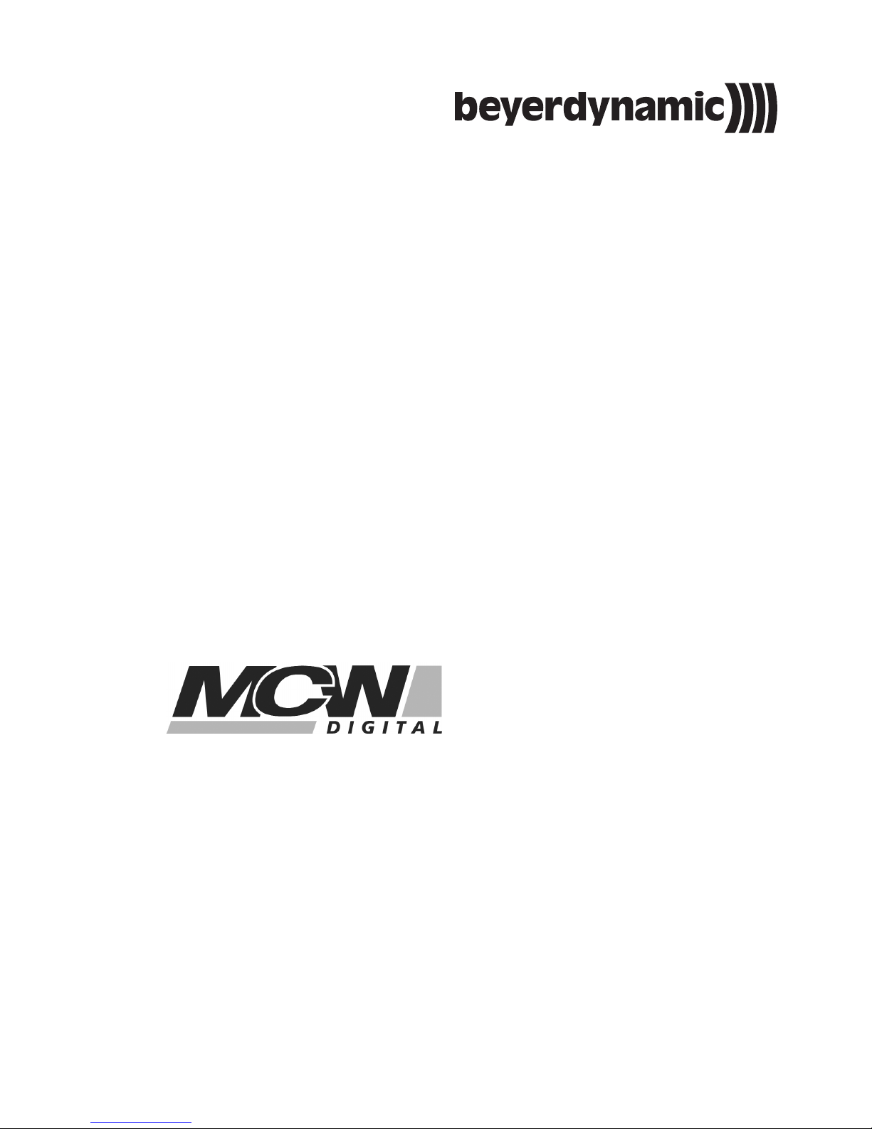
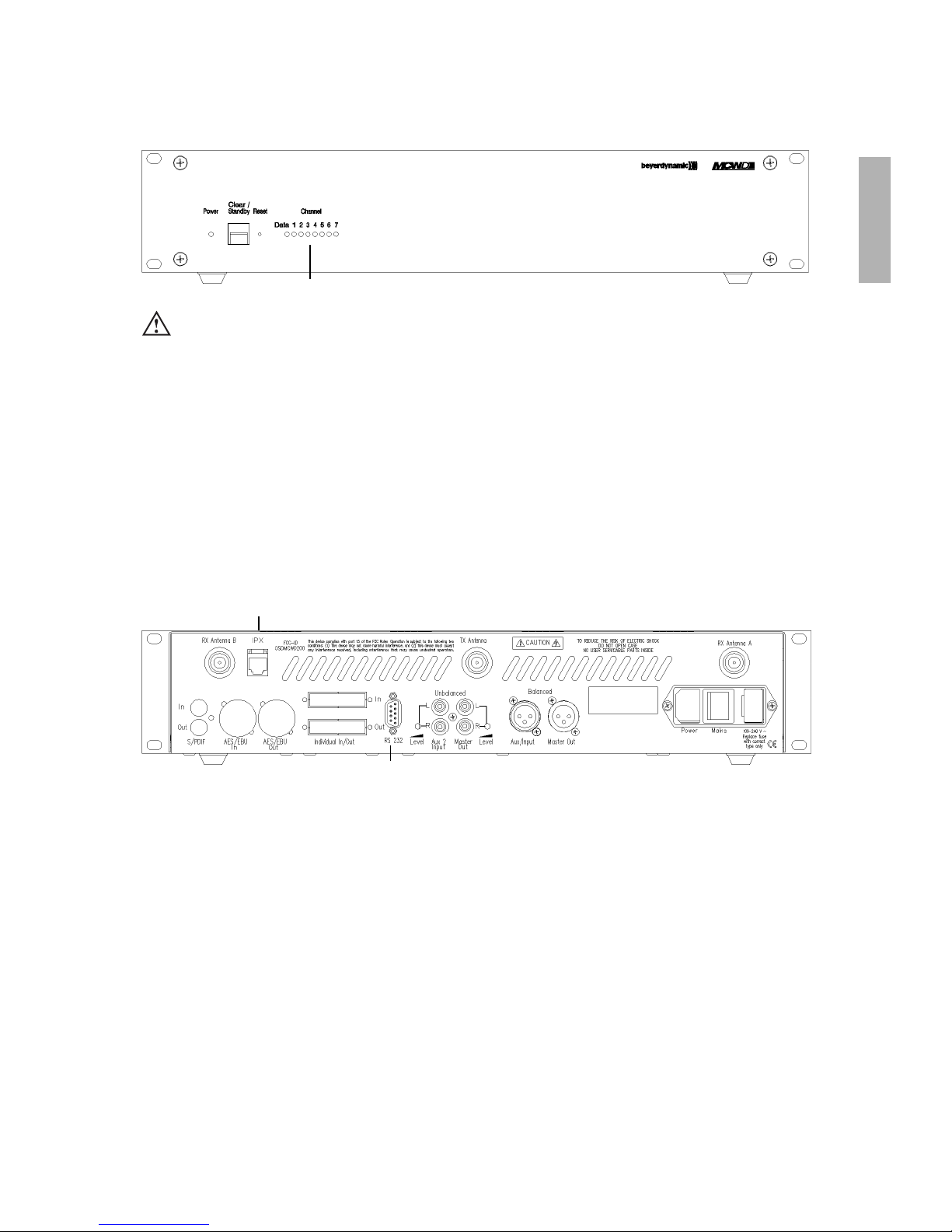
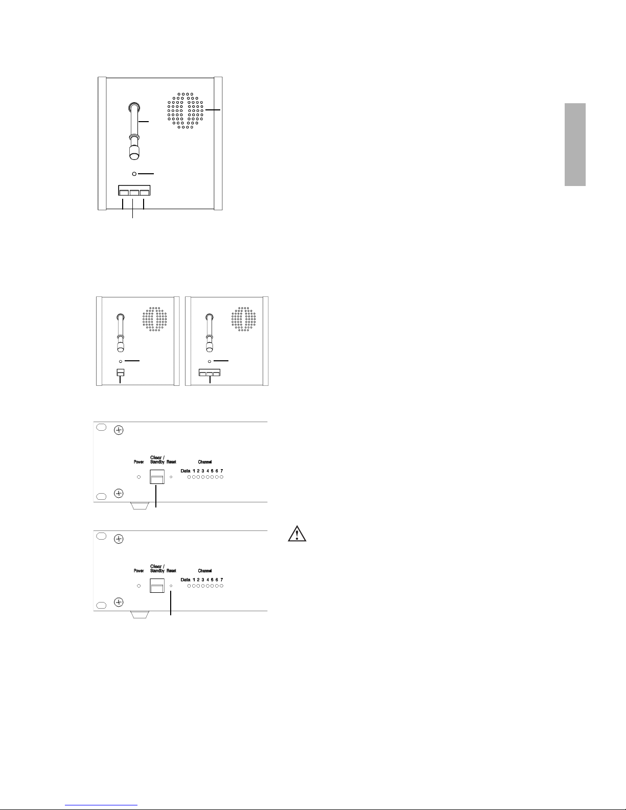
1.1 Bedien- und Kontrollelemente
Vorderseite
(1) Power-LED. LED leuchtet grün: Gerät ist eingeschaltet und betriebsbereit.
(2) Stand-By-Taster. Bei längerem Drücken (> 3 Sekunden) werden alle eingeschalteten Sprechstellen im Empfangsbereich
abgeschaltet. Bei kurzem Drücken werden alle zugeteilten Mikrofone abgeschaltet.
(3) Reset, setzt die Anlage in den Einschaltzustand zurück. (Versenkter Taster, z.B. mit Büroklammer bedienen.)
(4) LEDs für Status der Empfangskanäle. LED leuchtet grün: Kanal frei. LED leuchtet rot: Kanal belegt.
Standardeinstellung: Kanal „Data“ für Datenkommunikation. Kanal 1 - 4 für Sprechstellen, Kanäle 5 - 7 nicht bestückt.
(1) (2) (3) (4)
Sicherheitsinformationen
• Das Gerät muss so aufgestellt werden, dass die Steckverbindung leicht zugänglich ist.
• Das Gerät muss an eine Netz-Steckdose mit Schutzkontakt angeschlossen werden.
• Setzen Sie das Gerät niemals Regen oder hoher Feuchtigkeit aus. Installieren Sie es daher nicht in unmittelbarer Nähe
von Swimming Pools, Duschanlagen, feuchten Kellerräumen oder sonstigen Bereichen mit außergewöhnlich hoher
Luftfeuchtigkeit.
• Stellen Sie niemals mit Flüssigkeiten gefüllte Gegenstände (z.B. Vasen oder Trinkgläser) auf das Gerät.
• Installieren und betreiben Sie das Gerät auch niemals in unmittelbarer Nähe von Heizkörpern, Beleuchtungsanlagen
oder anderen wärmeerzeugenden Geräten.
• Verlegen Sie alle Kabel stets so, dass sie nicht durch scharfe Gegenstände geknickt oder gar durchgetrennt werden können.
• Schalten Sie bei allen Arbeiten an den Ein- und Ausgängen die Stromzufuhr aus.
• Überprüfen Sie, ob die Anschlusswerte mit der vorhandenen Netzstromversorgung übereinstimmen. Bei Anschluss des
Systems an die falsche Stromversorgung können ernsthafte Schäden entstehen.
• Stecken Sie weder Drähte noch andere Gegenstände durch die Lüftungsöffnungen des Gehäuses.
• Dieses Gerät benötigt eine ausreichende Ventilation. Decken Sie die Lüftungsöffnungen nicht ab.
• Stellen Sie niemals offene Brandquellen (z.B. Kerzen) auf das Gerät.
Page 5
5
deutsch
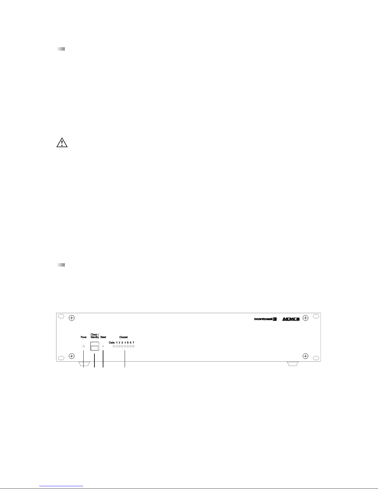
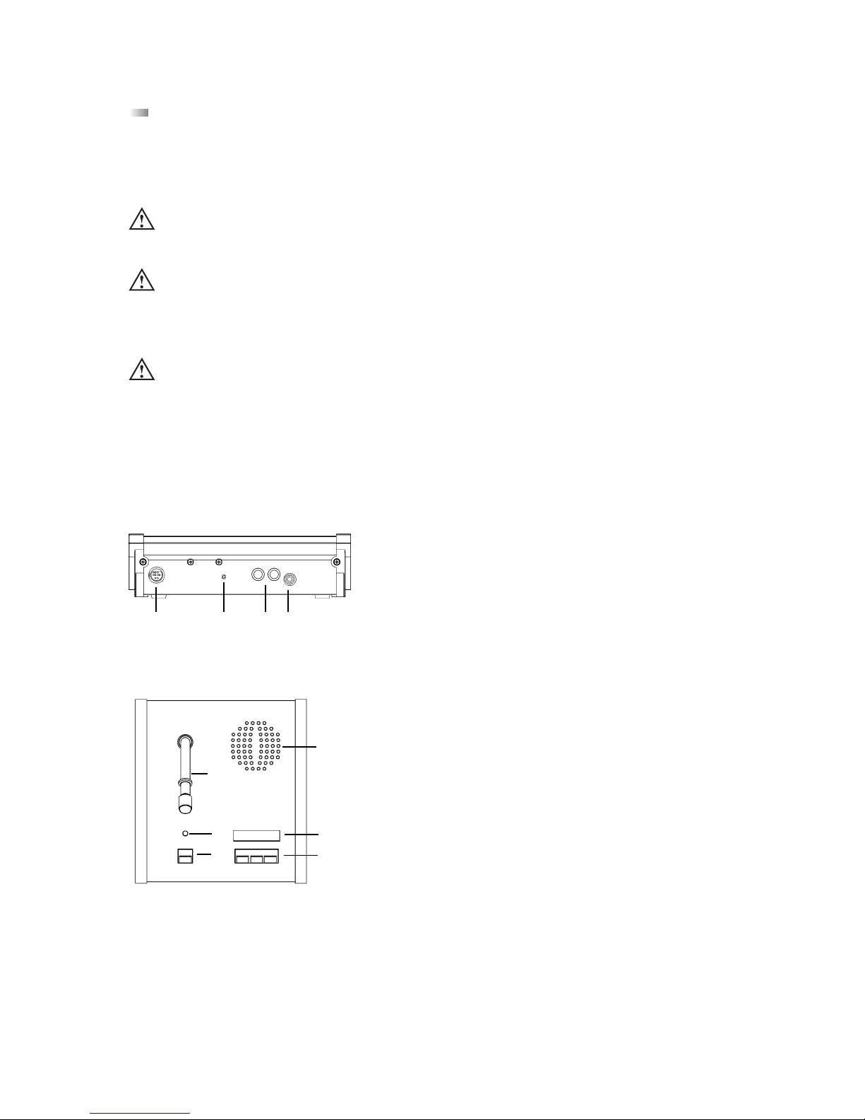
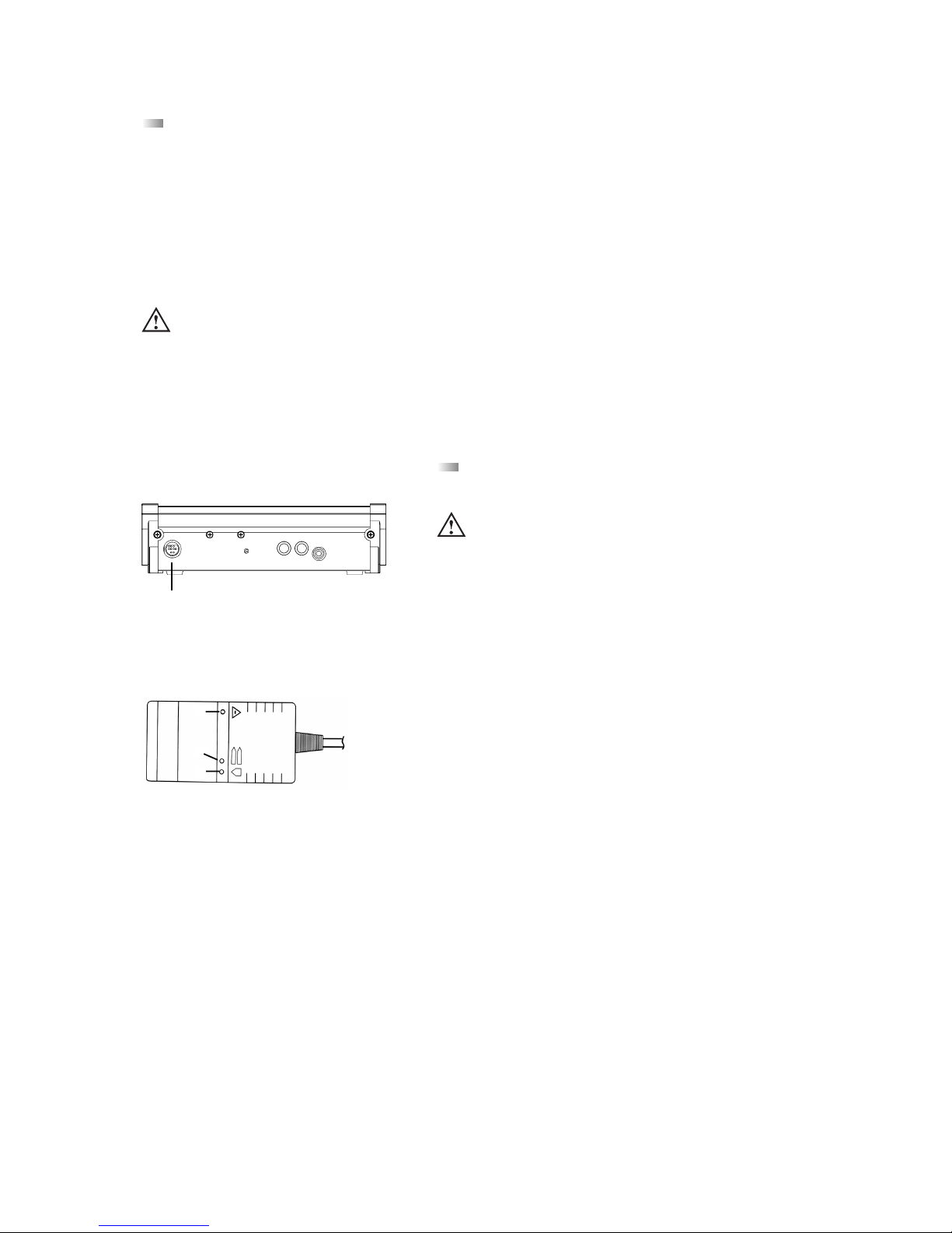
Rückseite
(5) IPX-Netzwerkanschluss (RJ 45 Steckverbinder)
(6) Anschluss für Empfangsantenne A/B (N-Steckverbinder)
(7) Netzsicherung
(8) Ein/Ausschalter
(9) Netzanschluss
(10) Master Out - Summenausgang, 3-pol. XLR male, symmetrisch, zum Anschluss externer Geräte wie z.B. Mischpult oder
Beschallungsanlage (+6 dBm)
(11) Aux 1 Input - Eingang, 3-pol. XLR female, symmetrisch, zum Einschleifen externer Signalquellen oder als Insert Return konfigu-
rierbar (+6 dm)
(12) Anschluss für Sendeantenne (N-Steckverbinder)
(13) Pegelsteller für Master Out - Summenausgang, Cinch
(14) Master Out - Summenausgang, Cinch, unsymmetrisch, zum Anschluss externer Geräten wie z.B. Mischpult, Beschallungs-
anlage oder Aufnahmegerät (L + R)
(15) Aux 2 Input - Eingang, Cinch, unsymmetrisch, zum Anschluss externer Geräten wie z.B. CD-Player (L + R)
(16) Pegelsteller für Aux 2 Input, Cinch
(17) Serielle Schnittstelle RS 232 für Anschluss von z.B. PC oder Mediensteuerung (9-pol. Sub-D)
Optionale Erweiterungen für weitere Anschlüsse.
(18) CA 2451 - Analoge Einzel-Ein-/Ausgänge (2 x 25 pol. Sub-D-Buchse) für z.B. Simultan-Dolmetscher-Betrieb und für einzelne
Sende-/Empfangssignale. Siehe auch Kapitel 2.1.
(19) CA 2452 - Digitale Ein-/Ausgänge, AES/EBU (XLR) und S/PDIF (Cinch)
1.2 Inbetriebnahme
1.2.1 Aufstellen der Steuerzentrale
• Stellen Sie die Steuerzentrale MCW-D 200 in dem Raum auf, in dem die Konferenz stattfindet.
• Stellen Sie die Steuerzentrale MCW-D 200 nicht neben digital gesteuerte Geräte.
(5)
(6)(7)(8)(9)(10)(11)(13) (12)(14)(15)(16)(17)(18)(19)(19)(19)(6)
1.2.2 Antennen anschließen
• Schließen Sie die Empfangsantennen an die Antenneneingänge A und B (6) an.
Für den Stand-Alone-Betrieb empfehlen wir die Stabwinkelantenne CA 2411.
• Schließen Sie die gewünschte Sendeantenne an den Antennenausgang (12) an.
Für den Stand-Alone-Betrieb empfehlen wir die Stabwinkelantenne CA 2411.
Wichtig:
• Antennen und Sprechstellen sollten Sichtkontakt haben, d.h. zwischen der Steuerzentrale MCW-D 200 und
den Sprechstellen dürfen keine Hindernisse sein. Bei Sichtverbindung zwischen Steuerzentrale und Sprechstelle
sowie den Stabwinkelantennen beträgt die Reichweite ca. 30 m innerhalb geschlossener Räume. Für die optimale Reichweite spielt auch die Oberflächenbeschaffenheit des Tisches eine Rolle. Ideal sind Holz- oder
Kunststofftische, bei Metalltischen ist unter Umständen die Abstrahlung und damit die max. erzielbare Reichweite
beeinträchtigt.
(6)(12)(6)
Page 6
6
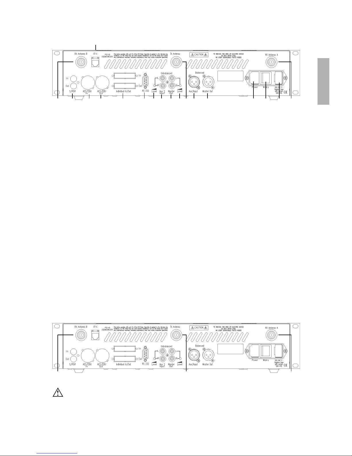
1.2.3 Audioanschluss
• Verbinden Sie den Summenausgang XLR (10) oder Cinch (14) der Steuerzentrale MCW-D 200 mit dem Eingang eines
Mischpultes / Mischverstärkers.
• Achten Sie darauf, dass die Kabel nicht geknickt oder durchtrennt werden können.
(10)(14)
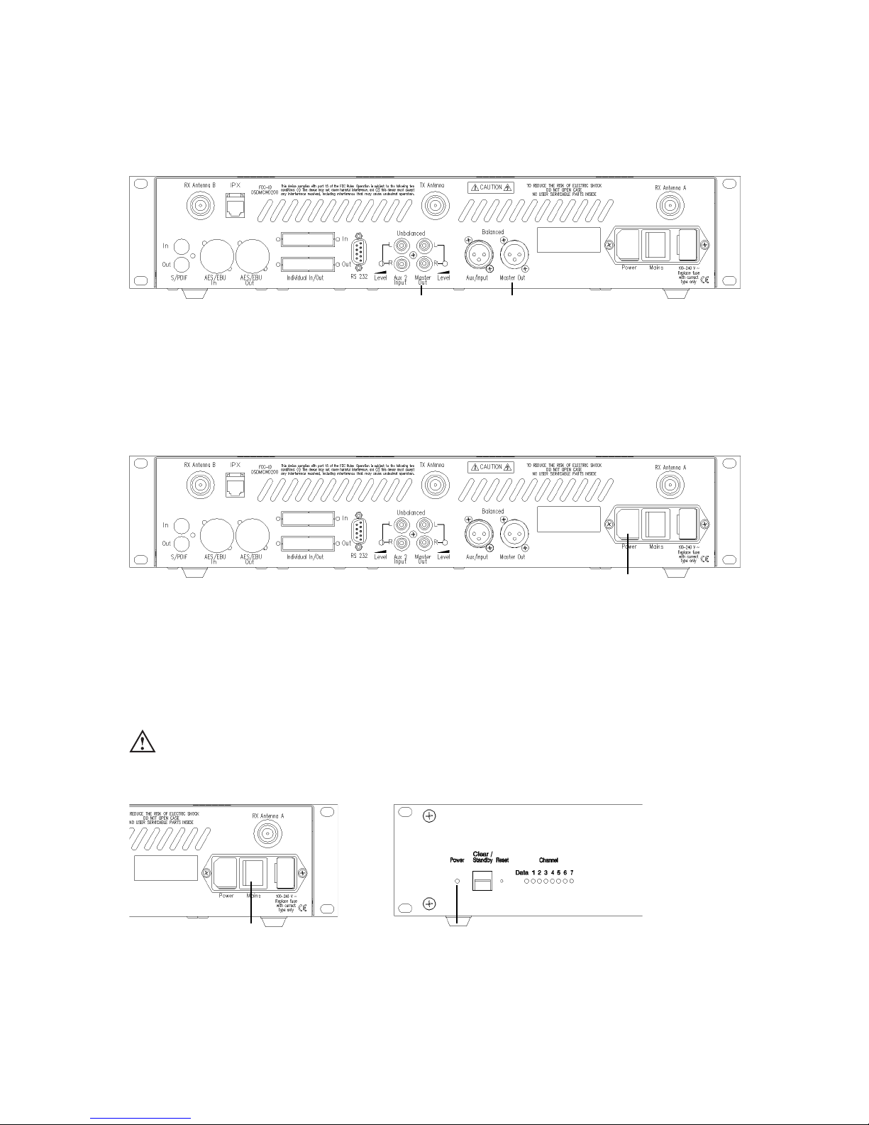
1.2.4 Netzanschluss
• Überprüfen Sie, ob die Anschlusswerte mit der vorhandenen Netzstromversorgung übereinstimmen. Bei Anschluss des Systems
an die falsche Stromversorgung können ernsthafte Schäden entstehen.
• Achten Sie darauf, dass das Netzkabel nicht geknickt oder durchtrennt werden kann.
• Schließen Sie die Steuerzentrale MCW-D 200 ans Netz (9) an. Das Netzteil der Steuerzentrale kann sich automatisch auf eine
Wechselspannung zwischen 90 und 240 Volt bei 50 - 60 Hz einstellen.
(9)
1.2.5 Ein-/Ausschalten
• Schalten Sie die Steuerzentrale MCW-D 200 mit dem Ein-/Ausschalter (8) auf der Rückseite ein oder aus.
• Während der ersten ca. 15 Sekunden wird die Steuerzentrale MCW-D 200 initialisiert und dabei blinkt die Power LED (1) grün.
In dieser Zeit ist kein Betrieb möglich.
• Die Power LED (1) auf der Vorderseite leuchtet grün, wenn die Steuerzentrale betriebsbereit ist.
Rückseite Vorderseite
(1)(8)
• ACHTUNG: Schalten Sie bei allen Arbeiten an den Ein- und Ausgängen das Gerät immer aus.
Page 7
7
deutsch
1.2.6 Kanal-Anzeige
• Je nach Bestückung der Steuerzentrale MCW-D 200 leuchten 5 oder mehr Kanal-LEDs (4) grün (Standard: 5 Kanäle).
(4)
1.2.7 Rackmontage
• Bei Montage in ein 19"-Rackgehäuse sollte über und unter der MCW-D 200 Steuerzentrale ein Lüftungsfeld von 1 HE
montiert werden.
1.2.8 Gleichzeitiger Betrieb von Mediensteuersystem und PC
• Wenn Sie ein Mediensteuersystem und einen PC gleichzeitig betreiben wollen, schließen Sie den PC an den IPX-Netzwerkanschluss (5) und das Mediensteuersystem an den RS 232-Anschluss (17) an.
• Für die Verbindung des IPX-Netzwerkanschlusses muss ein „Crossover“-Kabel verwendet werden.
• Die IPX-Einstellungen sind im Protokoll erläutert.
Wichtig:
• Sollten nicht mindestens 5 LEDs leuchten, kann es auch daran liegen, dass einzelne Kanäle mit der MCW-D 200 Editor
Software abgeschaltet wurden.
(5)
(17)
Page 8
8
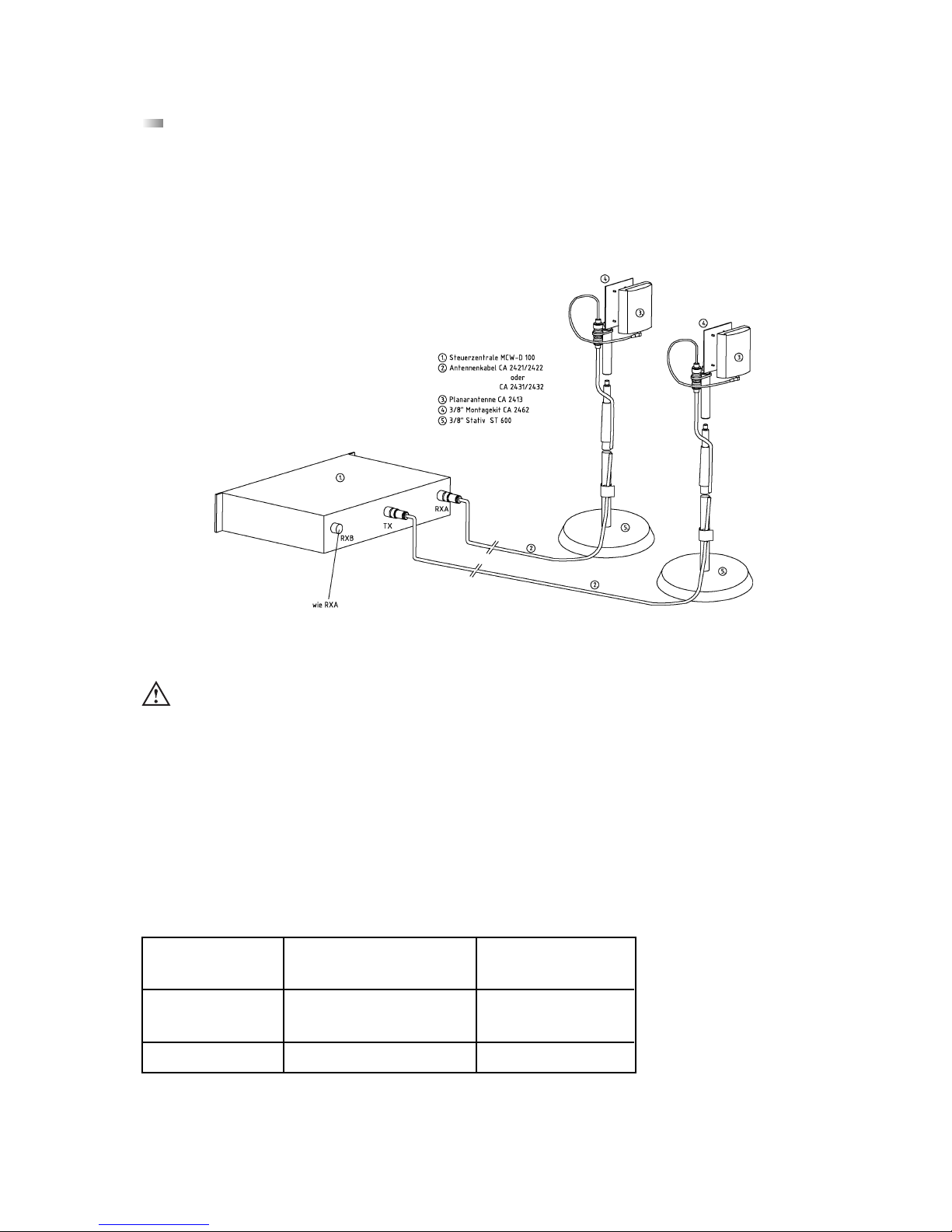
1.3 Anschließen abgesetzter Antennen
Die Steuerzentrale MCW-D 200 kann auch mit abgesetzten Antennen betrieben werden. Als Anschlusskabel dienen dämp-
fungsarme Kabel in verschiedenen Längen. Beachten Sie, dass alle drei Antennen abgesetzt montiert werden müssen. Die Sendeantenne sollte zentral und die beiden Empfangsantennen links und rechts montiert werden. Durch den Einsatz einer gerichteten
Antenne (CA 2413, Gewinn ca. 6 dB) kann die Reichweite verbessert werden.
Je nach Kabeldämpfung sollten Sie ab einer bestimmten Antennenkabellänge Antennenverstärker einsetzen.
Beispiel für variablen Aufbau mit abgesetzten Antennen
Wichtig:
• Antennen und Sprechstellen sollten Sichtkontakt haben, d.h. zwischen der Steuerzentrale MCW-D 200 und
den Sprechstellen dürfen keine Hindernisse sein. Bei Sichtverbindung zwischen Steuerzentrale und Sprechstelle
sowie den abgesetzten Antennen beträgt die Reichweite ca. 30 m innerhalb geschlossener Räume. Für die optimale Reichweite spielt auch die Oberflächenbeschaffenheit des Tisches eine Rolle. Ideal sind Holz- oder
Kunststofftische, bei Metalltischen ist unter Umständen die Abstrahlung und damit die max. erzielbare Reichweite
beeinträchtigt.
• Raumgröße: bis zu 400 m2 (20 x 20)
• Teilnehmerzahl: 30 - 100
• Antennenposition: am Rand der Sitzposition der Teilnehmer, möglichst hoch über dem
Tischniveau
• Ausrichtung: Antennen zu den Teilnehmern hin ausrichten (gewölbte Seite nach vorne)
Aircell 7
Standard
CA 2420
bis 20 m
= 1 x CA 2422
oder 2 x CA 2421
25 mm
Kabeltyp
Max. Kabellänge
Min. Biegeradius
Ecoflex 10
Low Attenuation
CA 2430
bis 40 m
40 mm
Die Planarantenne CA 2413 wird an die Steuerzentrale MCW-D 200 angeschlossen und mit dem Montagekit CA 2462 auf einem
Stativ befestigt. Weitere Installationsmöglichkeiten der Antennen finden Sie in unserem “MCW-D Design-Guide”.
Page 9
9
deutsch
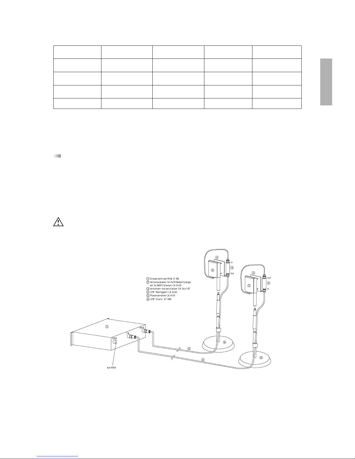
1.4 Fernspeisung der Antennensignalverstärker über Zentrale
Die Antennensignalverstärker können über die Steuerzentrale MCW-D 200 ferngespeist werden. Im Innern der
Steuerzentrale MCW-D 200 befindet sich eine Diagnose-LED, die durch die Lüftungsschlitze auf der Rückseite gesehen werden
kann.
Diese LED leuchtet grün, wenn die Fernspeisespannung an allen Antennenbuchsen 5 V beträgt.
Die LED blinkt rot, wenn an einer Antennenbuchse ein Kurzschluss auftritt. Überprüfen Sie in diesem Fall die Antennenverkabelung.
Die Fernspeisespannung von 5 V dient zur Versorgung der Antennensignalverstärker CA 2441 RT und CA 2441 T.
Kabeldämpfung der verschiedenen Kabeltypen bei 2,4 GHz
Kabellänge
100 m 50 m 30 m
RG 58 100 dB 50 dB 30 dB
RG 213 U 49 dB 24 dB 15 dB
Aircell 7, CA 2420 41 dB 20 dB 12 dB
Ecoflex 10, CA 2430 24 dB 12 dB 7 dB
ungeeignet
nur kurze Kabellänge
mittlere Kabellänge
längere Kabel
Wir empfehlen den Einsatz des Antennenverstärkers CA 2441 ab einer Kabeldämpfung von ca. 12 - 15 dB, d.h. beim Kabel
CA 2420 ab einer Länge von ca. 40 m und bei CA 2430 ab ca. 60 m.
ACHTUNG:
• Die Antennensignalverstärker CA 2441 RT und CA 2441 T dürfen nur mit 5 V DC betrieben werden.
• Bei Anschluss eines CA 2441 an den TX-Ausgang der MCW-D 200 muss ein Anschlusskabel mit mindestens 10 dB
Dämpfung eingesetzt werden.
Page 10
10
2.1 Zusätzliche Sende-/Empfangskanäle
Wenn in Konferenzen mehr als 4 Sprecher (z.B. 3 Delegierte und 1 Präsident oder 2 Delegierte und 2 Präsidenten) gleich-
zeitig sprechen sollen, benötigen Sie mehr Empfangskanäle. Hierfür wurde die Nachrüstplatine CA 2450 1 Sende- / 1 Empfangskanal entwickelt. Mit den Nachrüstplatinen CA 2450 kann die Steuerzentrale MCW-D 200 um bis zu 3 zusätzliche Sende/Empfangskanäle erweitert werden.
Standardmäßig sind 5 Sende-/Empfangskanäle bestückt. Diese entsprechen 1 Daten-Kommunikationskanal, 4 Sprechkanälen (z.B.
3 Delegierten- und 1 Präsidentensprechstelle können gleichzeitig eingeschaltet werden) und 5 Hörkanälen (Originalton für
Sprechstellenlautsprecher und für 4 Fremdsprachenkanäle bei Dolmetscheranwendung). Siehe auch Zeichnung 2.
Im voll bestückten Zustand mit 3 Nachrüstplatinen CA 2450 stellt die Steuerzentrale neben dem Datenkommunikationskanal
7 Sprechkanäle und 8 Hörkanäle zur Verfügung. Sollen die Hörkanäle für den Dolmetscherbetrieb genutzt werden, ist die
Nachrüstplatine CA 2451 notwendig (siehe Kapitel 2.2)!
2. Optionaler Einbau von Nachrüstplatinen für weitere Funktionen
CA 2450
CA 2451
CA 2452
für 1 zusätzlichen
Sende-/Empfangskanal
für Fremdsprachenbzw. Dolmetschanwendungen
zum Anschluß an
digitale Signalquellen
wie z.B. digitales
Mischpult
Wichtig:
• Bevor Sie den Einbau vornehmen, müssen Sie die MCW-D 200 Steuerzentrale vom Stromnetz trennen, d.h. den
Netzstecker aus der Steckdose ziehen.
Vorkehrungen zum ESD-Schutz
• Elektronische Bauelemente sind bei elektro-statischen Entladungen gefährdet (ESD = Electro-Static Discharge). Um
Zerstörung oder Schädigung von Komponenten durch ESD zu vermeiden, müssen die folgenden Vorkehrungen getroffen werden:
• Personen, die mit ESD-gefährdeten Bauteilen hantieren, sollten geerdet sein (z.B. durch ein Masseband am
Handgelenk).
• Es ist ein geeigneter Arbeitsbereich zu wählen. Teppiche oder andere Boden- bzw. Tischbeläge, die statische
Ladungen erzeugen können, sind zu meiden. Der Arbeitsbereich sollte frei sein von Gegenständen, die statische
Ladungen bewahren oder erzeugen können.
• ESD-gefährdete Komponenten müssen sorgfältig behandelt werden. Reiben über irgendwelche Oberflächen, das
Berühren von vorstehenden Pins, von Leiterbahnen usw. sollte vermieden werden. Halten Sie eine Baugruppe oder
ein Modul möglichst nur an den Rändern.
• Gefährdete Komponenten oder Baugruppen müssen in anti-statischer oder leitender Verpackung transportiert und
gelagert werden.
Page 11
11
deutsch
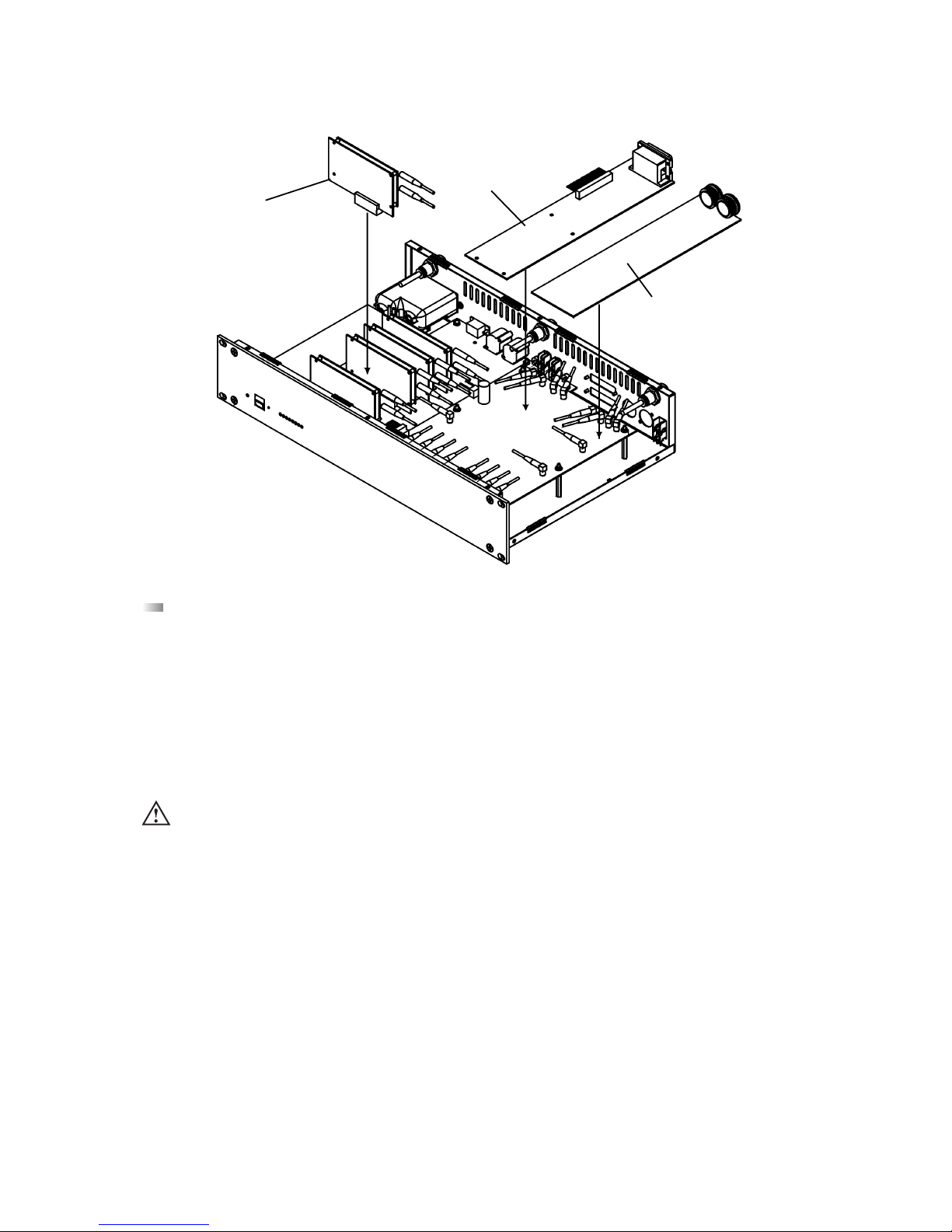
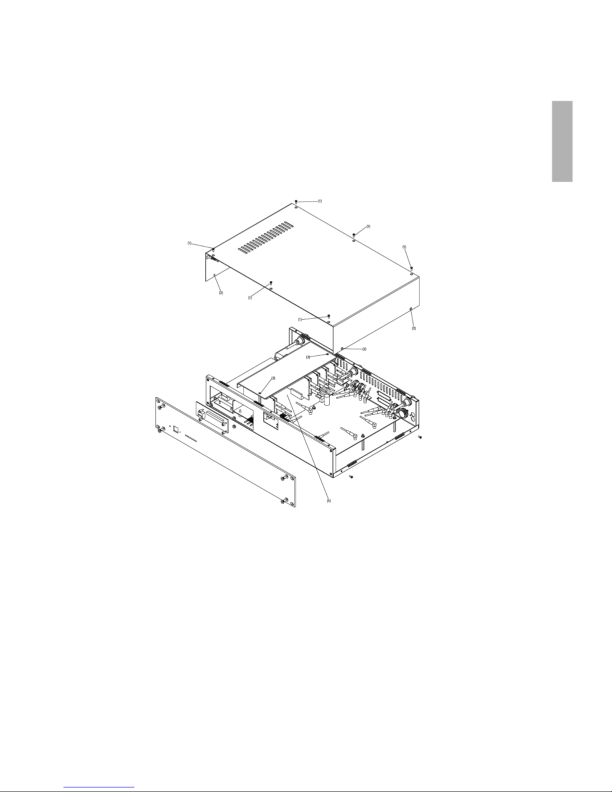
Zeichnung 1
Nehmen Sie den Einbau wie folgt vor:
1. Lösen Sie die Schrauben oben (1) und an den Seiten (2) der MCW-D 200 und nehmen Sie die Abdeckung herunter.
2. Lösen Sie die Schrauben des Sicherungsbügels (3) und stecken Sie die Platine auf einen freien Slot (4).
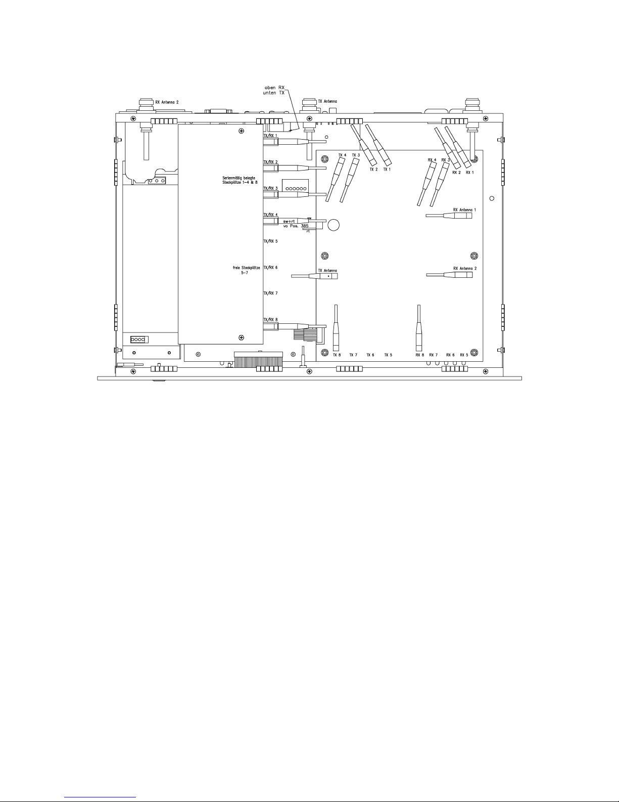
3. Stecken Sie das Kabel der Platine auf den entsprechenden Antennenanschluß auf. Achten Sie darauf, dass Sie die Anschlüsse
nicht vertauschen. Siehe hierzu Zeichnung 2. Anschlüsse von z B. TX/RX 6 an TX 6 und RX 6, von TX/RX 7 an TX 7 und RX 7
usw. anschließen.
4. Setzen Sie die Abdeckung wieder auf die MCW-D 200 auf und ziehen Sie die Schrauben fest. Achten Sie darauf, dass das gelbgrüne Schutzleiterkabel sich nicht vom Deckel ablöst.
5. Nach dem Einbau von Modulen müssen die Kanäle mit Hilfe der MCW-D 200 Editor Software eingestellt werden.
Page 12
12
Zeichnung 2
Page 13
13
deutsch
2.2 Fremdsprachige Konferenzen / Dolmetschanwendungen
Für Konferenzen mit mehreren Fremdsprachen bzw. Dolmetschanwendungen ist die Nachrüstplatine CA 2451 erhältlich.
Wichtig:
Der Einbau der Nachrüstplatine CA 2451 wird bei Bedarf im Werk bzw. bei der autorisierten Vertretung Ihres Landes vorgenommen.
Über die Nachrüstplatine CA 2451 werden zum einen die Audiosignale der einzelnen eingeschalteten Sprechstellen getrennt zur
Verfügung gestellt und zum anderen die einzelnen Audioeingänge für die Hörkanäle bei Dolmetscheranwendungen (Originalton
und Fremdsprachen) genutzt. Je nach Anzahl der eingebauten Nachrüstplatinen CA 2450 (1 Sende- und Empfangskanal) können
getrennte Audiosignale von bis zu 7 eingeschaltete Sprechstellen abgehört und bis zu 8 Audiosignale für die Hörkanäle eingespielt werden.
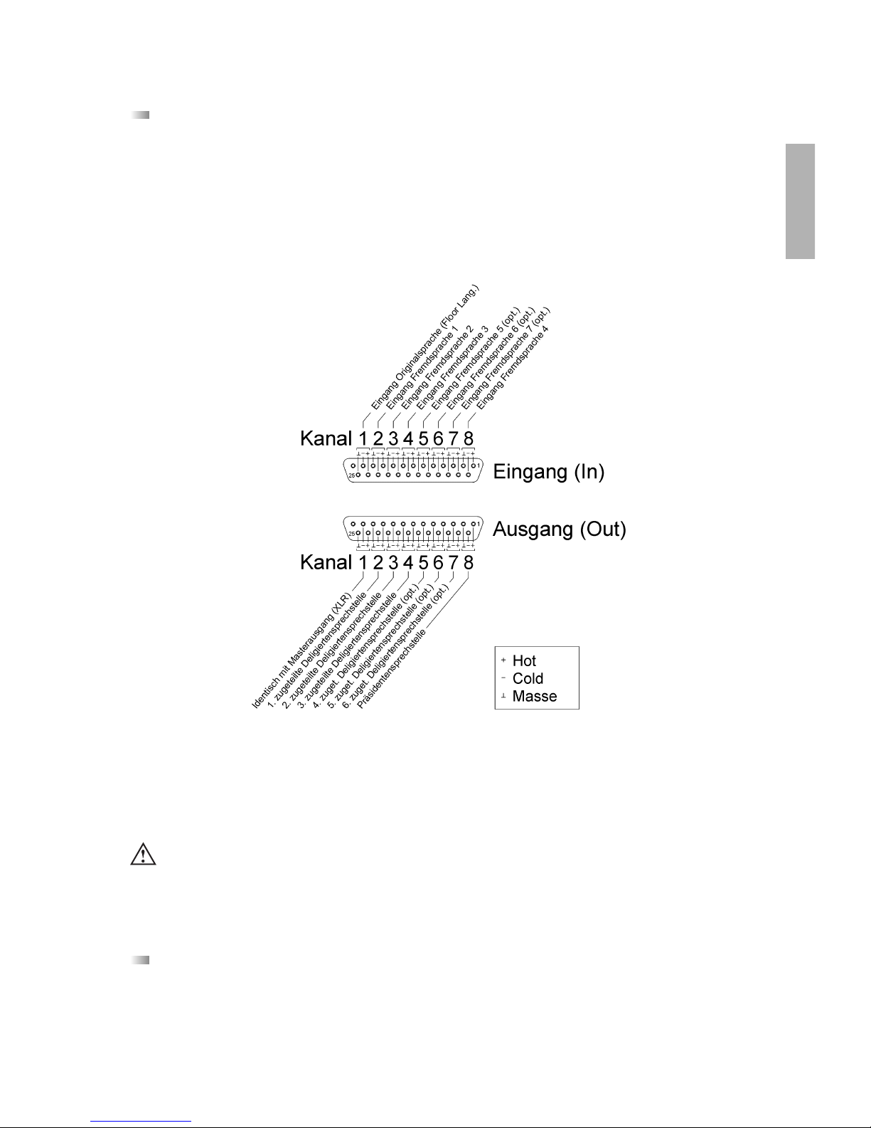
Die Anschlussbelegung entspricht der bei Tascam-DA-XX-Recordern. Für ein Eingangssplittkabel (25-pol. Sub-D, male auf XLR,
female) kann ein handelsübliches Kabel mit der Typenbezeichnung Tascam CU SD 303 (3 m) oder Tascam CU SD 305 (5 m) verwendet werden.
Für ein Ausgangssplittkabel (25-pol. Sub-D, male auf XLR, male) kann ein handelsübliches Kabel mit der Typenbezeichnung
Tascam CU SD 203 (3 m) oder Tascam CU SD 205 (5 m) verwendet werden.
2.3 CA 2452 Digitale Ein- und Ausgänge AES/EBU und S-PDIF
Diese Nachrüstplatine ist zur Zeit noch nicht erhältlich.
Wichtig:
• Der Eingangspegel beträgt max. +6 dBm; d.h. das angeschlossene Gerät darf auch bei lauten Stellen kein höheres Signal
erzeugen.
Page 14
14
3. Delegierten- und Präsidentensprechstellen
• Damit die Steuerzentrale MCW-D 200 die Sprechstellen gezielt steuern kann, wird im Werk jeder Sprechstelle eine andere
Adresse / Seriennummer einprogrammiert.
• Diese Adresse / Seriennummer, die nicht geändert werden kann, ist auf der Unterseite der jeweiligen Sprechstelle aufgedruckt.
• Bei Nachbestellungen sollte der Anwender die Konfiguration der Steuerzentrale mitteilen und welche Sprechstellen er schon
in Betrieb hat.
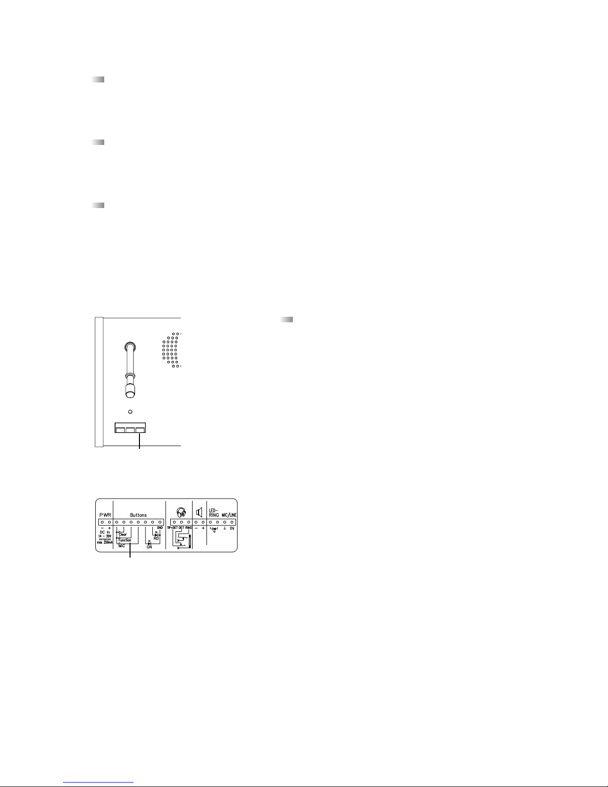
3.1 Sprechstellen MCW-D 2011/2013 und MCW-D 2021/2023
Die Sprechstellen MCW-D 2011/2013 und MCW-D 2021/2023 eignen sich für einsprachige Konferenzen ohne Abstimmung.
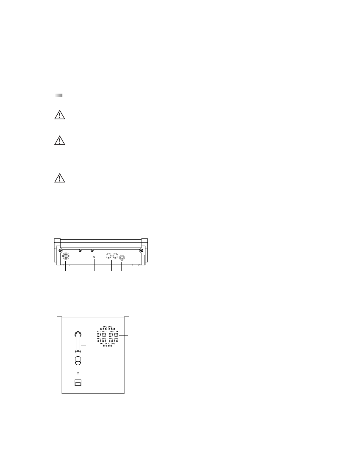
(1) Multifunktionsbuchse (Anschluss von Einzel-Ladeadapter
oder DC-Speisung)
(2) Betriebskontroll-LED
(3) Ladekontakte für Ladegerät MCW-D 10, LE-D 10 bzw.
DC-Anschluss bei DC-gespeisten Sprechstellen
(4) 3,5 mm Stereo-Klinken-Buchse zum Anschluss für Recorder oder
Kopfhörer (z.B. DT 1)
(5) Schwanenhalsmikrofon mit Leuchtring
(6) Lautsprecher (nur bei MCW-D 2021)
(7) LED zur Funktionsanzeige (grün/rot)
(8) Mikrofontaste
(6)
(5)
(7)
(8)
Oberseite Delegierte MCW-D 2011 / 2021
(1) (2) (3) (4)
Rückseite
3.1.1 Bedien- und Kontrollelemente
Wichtig:
• Entfernen Sie vor Gebrauch der Sprechstelle die Transportsicherung (Kartonage) aus den Ladefächern der Sprechstellen
im Lade- und Transportkoffer MCW-D 10. Beim weiteren Transport sollte die Transportsicherung wieder in das jeweilige Ladefach gelegt werden.
• Die Ladekontakte (3) der Sprechstellen können Sachbeschädigungen, Verletzungen oder Brandschäden verursachen,
wenn die Kontakte mit leitenden Materialien wie Schmuck, Schlüsseln oder Ketten in Berührung kommen. Dies kann zu
einem geschlossenen Stromkreis und dadurch zur Erhitzung des Materials führen.
• Um einen solchen ungewollten Stromkreis zu vermeiden, müssen die Ladekontakte (3) mit Vorsicht behandelt werden.
Dies gilt insbesondere dann, wenn die Sprechstellen in einer Tasche oder einem anderen Behälter zusammen mit metallischen Gegenständen transportiert werden.
• Zum Ausrichten des Schwanenhalsmikrofons der Sprechstelle und zum Vermeiden einer Überdehnung und
frühzeitigen Verschleißerscheinungen, fassen Sie das Mikrofon immer am unteren flexiblen Teilstück an,
niemals oben am Mikrofonkopf oder am starren Rohr. Der Schwanenhals darf nur bis max. 90 Grad gebogen werden.
Page 15
15
deutsch
3.1.3 DC-gespeiste Versionen MCW-D 2021 DC und MCW-D 2023 DC
• Die Sprechstellen MCW-D 2021 DC und MCW-D 2023 DC werden nicht über einen integrierten Akkus, sondern über Gleichstrom
gespeist.
• Der Anschluss des Netzkabels erfolgt im Einkabelprinzip. Schließen Sie die erste Sprechstelle mit einem geeigneten Netzteil an.
Schließen Sie die zweite Sprechstelle an die erste an, die dritte an die zweite usw. bis alle Sprechstellen angeschlossen sind.
Bezüglich eines geeigneten Netzteils setzen Sie sich bitte mit Ihrer beyerdynamic-Vertretung in Verbindung.
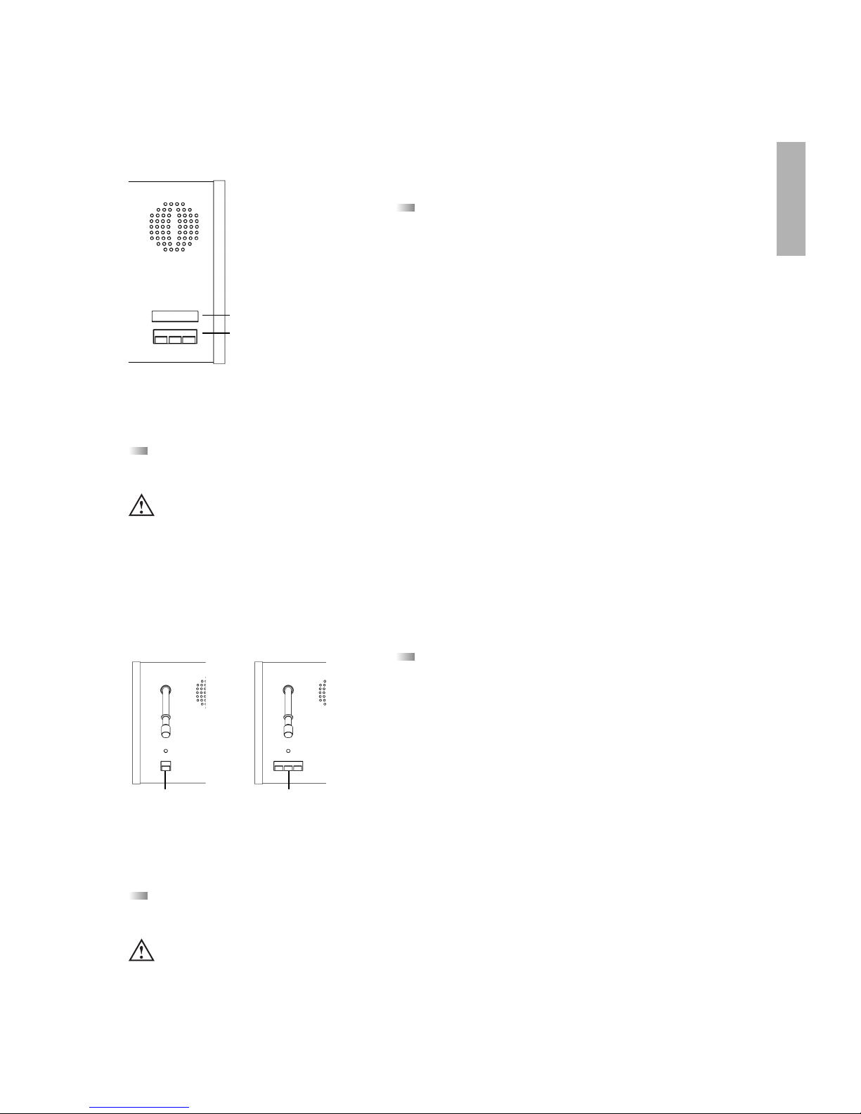
(6)
(5)
(7)
(8)
(8) (8)
(9)
(10)
(5) Schwanenhalsmikrofon mit Leuchtring
(6) Lautsprecher (nur bei MCW-D 2023)
(7) LED zur Funktionsanzeige (grün/rot)
(8) Mikrofontaste
(9) Clear-Taste zum Löschen der Delegierten-Sprechstellen
(10) Programmierbare Funktionstaste (siehe auch Kapitel 4.3)
Oberseite Präsident MCW-D 2013 / 2023
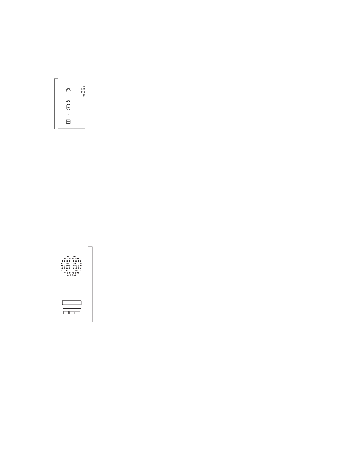
Einschalten
• Die Sprechstellen haben keinen separaten Ein-/Ausschalter. Sie werden
über die Mikrofontaste (8) ein- und ausgeschaltet.
• Durch kurzes Drücken wird die Sprechstelle eingeschaltet. Dabei
leuchtet die LED (7) kurz auf und die grüne Betriebskontroll-LED (2)
auf der Rückseite leuchtet.
Ausschalten
• Durch langes Drücken (> 2 Sek.) wird die Sprechstelle ausgeschaltet,
wobei die LED (7) zweimal kurz orange blinkt.
• Alle eingeschalteten MCW-D Sprechstellen in „Reichweite“ der
Steuerzentrale MCW-D 200 können auch über die Steuerzentrale ausgeschaltet werden, wenn Sie den Standby-Taster (2) länger als
3 Sekunden drücken.
• Außerdem schalten sich die Sprechstellen selbsttätig aus, wenn sie länger als ca. 3 Minuten kein Signal von der Steuerzentrale MCW-D 200
mehr empfangen.
3.1.2 Ein-/Ausschalten
Delegierte
MCW-D 200
Präsident
(7) (7)
(2)
(3)
Wichtig:
• Befindet sich die Sprechstelle außerhalb der Reichweite der
Steuerzentrale MCW-D 200, blinkt die LED (7) immer wieder
kurz rot auf. Nach ca. 3 Minuten schaltet sich die Sprechstelle
dann automatisch ab.
• Sollte das System nicht funktionieren, d.h. die Sprechstelle
wird eingeschaltet, es ist aber kein Ton zu hören, drücken Sie
auf die Reset-Taste (3) an der Steuerzentrale. Sollte das System
trotzdem nicht funktionieren, prüfen Sie die Audioeinstellungen mit der MCW-D 200 Editor Software. Funktioniert
das System immer noch nicht, setzen Sie sich bitte mit Ihrer
beyerdynamic-Vertretung in Verbindung.
Page 16
16
3.2 Sprechstellen MCW-D 2071 und 2073 mit Display
Die Sprechstellen MCW-D 2071 und MCW-D 2073 wurden für Dolmetschanwendungen entwickelt und funktionieren im
Prinzip wie die anderen MCW-D Sprechstellen. Sie verfügen jedoch zusätzlich über drei weitere Tasten und ein Display. Mit diesen Tasten können z.B. Kanal, Kopfhörerpegel und Gesamtlautstärke eingestellt werden sowie die Restbetriebszeit abgelesen
werden.
Das Display verfügt über eine Beleuchtung, die bei jedem Tastendruck aktiviert wird und nach ca. 10 Sekunden automatisch
erlischt.
(1) Multifunktionsbuchse (Anschluss von Einzel-Ladeadapter
oder DC-Speisung)
(2) Betriebskontroll-LED
(3) Ladekontakte für Ladegerät MCW-D 10, LE-D 10 bzw.
DC-Anschluss bei DC-gespeisten Sprechstellen
(4) 3,5 mm Stereo-Klinken-Buchse zum Anschluss für Recorder oder
Kopfhörer (z.B. DT 1)
Rückseite
(5) Schwanenhalsmikrofon mit Leuchtring
(6) Lautsprecher
(7) LED zur Funktionsanzeige (grün/rot)
(8) Mikrofontaste
(11) LC-Display
(12) Tasten für Einstellungen
(6)
(5)
(7)
(8)
(11)
(12)
Oberseite Delegierte MCW-D 2071
(1) (2) (3) (4)
3.2.1 Bedien- und Kontrollelemente
Wichtig:
• Entfernen Sie vor Gebrauch der Sprechstelle die Transportsicherung (Kartonage) aus den Ladefächern der Sprechstellen
im Lade- und Transportkoffer MCW-D 10. Beim weiteren Transport sollte die Transportsicherung wieder in das jeweilige Ladefach gelegt werden.
• Die Ladekontakte (3) der Sprechstellen können Sachbeschädigungen, Verletzungen oder Brandschäden verursachen,
wenn die Kontakte mit leitenden Materialien wie Schmuck, Schlüsseln oder Ketten in Berührung kommen. Dies kann zu
einem geschlossenen Stromkreis und dadurch zur Erhitzung des Materials führen.
• Um einen solchen ungewollten Stromkreis zu vermeiden, müssen die Ladekontakte (3) mit Vorsicht behandelt werden.
Dies gilt insbesondere dann, wenn die Sprechstellen in einer Tasche oder einem anderen Behälter zusammen mit metallischen Gegenständen transportiert werden.
• Zum Ausrichten des Schwanenhalsmikrofons der Sprechstelle und zum Vermeiden einer Überdehnung und
frühzeitigen Verschleißerscheinungen, fassen Sie das Mikrofon immer am unteren flexiblen Teilstück an,
niemals oben am Mikrofonkopf oder am starren Rohr. Der Schwanenhals darf nur bis max. 90 Grad gebogen werden.
Page 17

17
deutsch
(6)
(5)
(7)
(8)
(9)
(10)
(5) Schwanenhalsmikrofon mit Leuchtring
(6) Lautsprecher
(7) LED zur Funktionsanzeige (grün/rot)
(8) Mikrofontaste
(9) Clear-Taste zum Löschen der Delegierten-Sprechstellen
(10) Programmierbare Funktionstaste (siehe auch Kapitel 4.3)
(11) LC-Display
(12) Tasten für Einstellungen
Oberseite Präsident MCW-D 2073
(11)
(12)
(8) (8)
Einschalten
• Die Sprechstellen haben keinen separaten Ein-/Ausschalter. Sie werden
über die Mikrofontaste (8) ein- und ausgeschaltet.
• Durch kurzes Drücken wird die Sprechstelle eingeschaltet. Dabei
leuchtet die LED (7) kurz auf und die grüne Betriebskontroll-LED (2)
auf der Rückseite leuchtet.
Ausschalten
• Durch langes Drücken (> 2 Sek.) wird die Sprechstelle ausgeschaltet,
wobei die LED (7) zweimal kurz orange aufleuchtet.
• Alle eingeschalteten MCW-D Sprechstellen in „Reichweite“ der
Steuerzentrale MCW-D 200 können auch über die Steuerzentrale ausgeschaltet werden, wenn Sie den Standby-Taster (2) länger als
3 Sekunden drücken.
• Außerdem schalten sich die Sprechstellen selbsttätig aus, wenn sie länger als ca. 3 Minuten kein Signal von der Steuerzentrale MCW-D 200
mehr empfangen.
3.2.2 Ein-/Ausschalten
MCW-D 2071
MCW-D 200
MCW-D 2073
(7) (7)
(2)
(3)
Wichtig:
• Befindet sich die Sprechstelle außerhalb der Reichweite der
Steuerzentrale MCW-D 200, blinkt die LED (7) immer wieder
kurz rot auf. Nach ca. 3 Minuten schaltet sich die Sprechstelle
dann automatisch ab.
• Sollte das System nicht funktionieren, d.h. die Sprechstelle
wird eingeschaltet, es ist aber kein Ton zu hören, drücken Sie
auf die Reset-Taste (3) an der Steuerzentrale. Sollte das System
trotzdem nicht funktionieren, prüfen Sie die Audioeinstellungen mit der MCW-D 200 Editor Software. Funktioniert
das System immer noch nicht, setzen Sie sich bitte mit Ihrer
beyerdynamic-Vertretung in Verbindung.
• Die Sprechstellen MCW-D 2071 DC und MCW-D 2033 DC werden nicht über einen integrierten Akkus, sondern über Gleichstrom
gespeist.
• Der Anschluss des Netzkabels erfolgt im Einkabelprinzip. Schließen Sie die erste Sprechstelle mit einem geeigneten Netzteil an.
Schließen Sie die zweite Sprechstelle an die erste an, die dritte an die zweite usw. bis alle Sprechstellen angeschlossen sind.
Bezüglich eines geeigneten Netzteils setzen Sie sich bitte mit Ihrer beyerdynamic-Vertretung in Verbindung.
3.2.3 DC-gespeiste Versionen MCW-D 2071 DC und MCW-D 2073 DC
Page 18
18
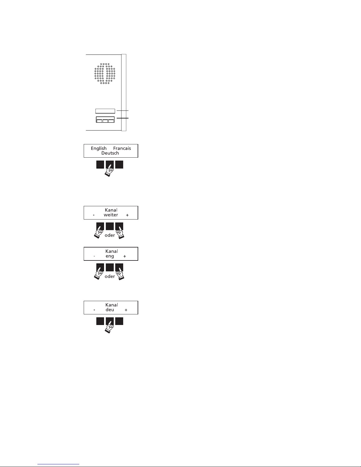
Kanal / Sprache einstellen
Über einen an die Sprechstelle angeschlossenen Kopfhörer kann
der Teilnehmer die gewünschte Sprache hören. Zum Einstellen
der Original- oder Fremdsprache bzw. des entsprechenden
Kanals drücken Sie die linke oder rechte Taste.
Drücken Sie die mittlere Taste, um die Einstellung zu verlassen
und um zum nächsten Menüpunkt „Kopfhörerpegel“ zu gelangen.
Sprachauswahl
Schalten Sie die Sprechstelle MCW-D 2071/2073 ein. Drücken Sie
gleichzeitig die rechte und linke Taste für ca. 2 Sekunden.
Wählen Sie die gewünschte Sprache aus.
Die nachfolgend aufgeführten Funktionen werden mit den
Tasten (12) unterhalb des Displays (11) eingestellt.
3.2.4 Einstellbare Funktionen MCW-D 2071 und MCW-D 2073
(11)
(12)
Page 19
19
deutsch
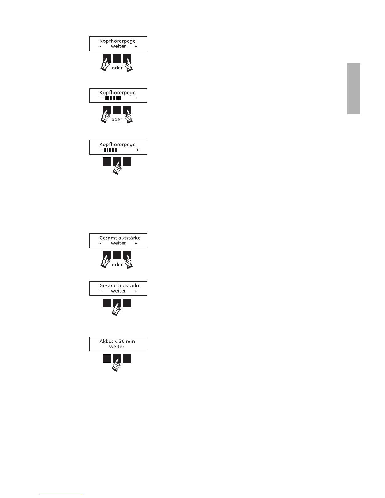
Kopfhörerpegel einstellen
Zum Einstellen des Kopfhörerpegels drücken Sie die linke oder
rechte Taste.
Lautstärke einstellen
(nur bei MCW-D 2073)
Zum Einstellen der Lautstärke des Konferenzsystems drücken Sie
die linke oder rechte Taste. Die Lautstärke wird ohne Anzeige im
Display verändert.
In der MCW-D 200 Editor Software kann eingestellt werden, welcher Lautstärke-Regler (Summe, Aux oder Lautstärke des
Rückkanals) verändert wird.
Drücken Sie die mittlere Taste, um die Einstellung zu verlassen
und um zum nächsten Menüpunkt „Akku“ zu gelangen.
Drücken Sie die mittlere Taste, um die Einstellung zu verlassen
und um zum nächsten Menüpunkt „Gesamtlautstärke“ zu gelangen.
Anzeige Restbetriebszeit
In diesem Menüpunkt können Sie die Restbetriebszeit der
Sprechstelle ablesen.
Je nach Kapazität des Akkus wird eine Betriebszeit von:
> 60 Minuten
< 60 Minuten
< 30 Minuten
angezeigt.
Page 20
20
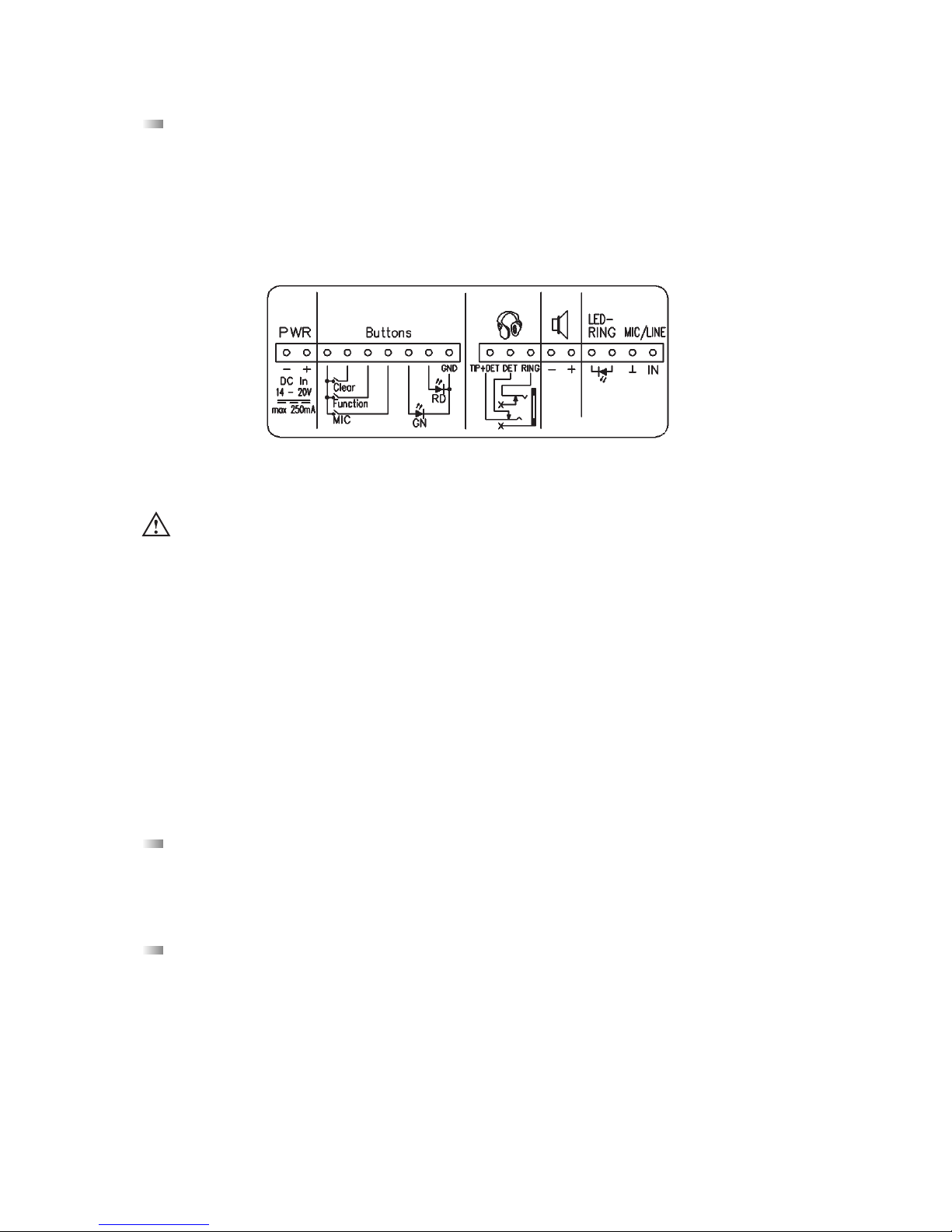
(1) Schraubklemmleiste 1 mit Anschlüssen für: Betriebsspannung, Tasten und LED
(2) Schraubklemmleiste 2 mit Anschlüssen für: Kopfhörer, Lautsprecher, externes Mikrofon und LED-Ring
(3)
(4)
(1)
(2)
3.3.1 Anschlüsse
3.3.2 Installation
1. Für Mikrofon und Taster werden zunächst entsprechende Ausschnitte in der Tischplatte benötigt.
2. Befestigen Sie die Sprechstelle unter dem Tisch. Optional ist hierfür der Befestigungsbügel CA 2472 erhältlich.
3. Tasten, Betriebsspannung, Mikrofon, Lautsprecher und je nach Bedarf Kopfhörer können Sie an die entsprechenden
Anschlüsse anschließen.
Hinweis:
Die Antenne der Sprechstelle muss, wenn sie direkt aufgesteckt wird, mindestens 12 cm (1 Wellenlänge) lang sein.
3.3 Systemanschlusseinheit MCW-D 2673
Die Systemanschlusseinheit MCW-D 2673 wurde für die Untertischmontage entwickelt und funktioniert im Prinzip wie
die MCW-D Sprechstellen MCW-D 2073 bzw. MCW-D 2071. Mit einer Mikrofontaste wird die MCW-D 2673 als Delegiertensprechstelle, mit drei Tasten (Mikrofon-, Clear- und Priortaste) als Präsidentensprechstelle eingesetzt.
Mit der abgesetzten Bedieneinheit CA 2473 mit Display und drei weiteren Tasten kann die Sprechstelle auch für Abstimmungen
oder Dolmetschanwendungen eingesetzt werden. Mit diesen Tasten können z.B. Kanal, Kopfhörerpegel und Gesamtlautstärke
eingestellt werden.
Das Display verfügt über eine Beleuchtung, die bei jedem Tastendruck aktiviert wird und nach ca. 10 Sekunden automatisch
erlischt.
3.3.3 Ein-/Ausschalten
Die Systemanschlusseinheit wird über die angeschlossene Mikrofontaste per Tastendruck ein- und ausgeschaltet.
3.3.4 Systemanschlusseinheit mit Display
Wird die Systemanschlußeinheit MCW-D 2673 mit der Bedieneinheit CA 2473-2 ergänzt, kann die Sprechstelle für
Abstimmungen oder Dolmetschanwendungen eingesetzt werden. Sie verfügen dann zusätzlich über drei weitere Tasten und ein
Display. Mit diesen Tasten können Kanal/Sprache, Kopfhörerpegel und Gesamtlautstärke eingestellt werden. Die Funktion
„Restbetriebszeit“ ist bei MCW-D 2673 nicht verfügbar.
Das Display verfügt über eine Beleuchtung, die bei jedem Tastendruck aktiviert wird und nach ca. 10 Sekunden automatisch erlischt. Genaue Beschreibung der einzelnen Funktionen siehe Kapitel „3.2.4 Einstellbare Funktionen bei MCW-D 2071 und MCW-D 2073“.
MCW-D 2673
Wichtig:
• Werden die 3 Pins für die Kopfhörerbuchse nicht benutzt, müssen die Pins „TIP+DET“ und „DET“ gebrückt werden, da
sonst die Sprechstelle unter Umständen so reagiert, als ob ein Kopfhörer angeschlossen wäre und auf dem falschen
Kanal empfängt (LED und Leuchtring blinken rot).
Page 21
21
deutsch
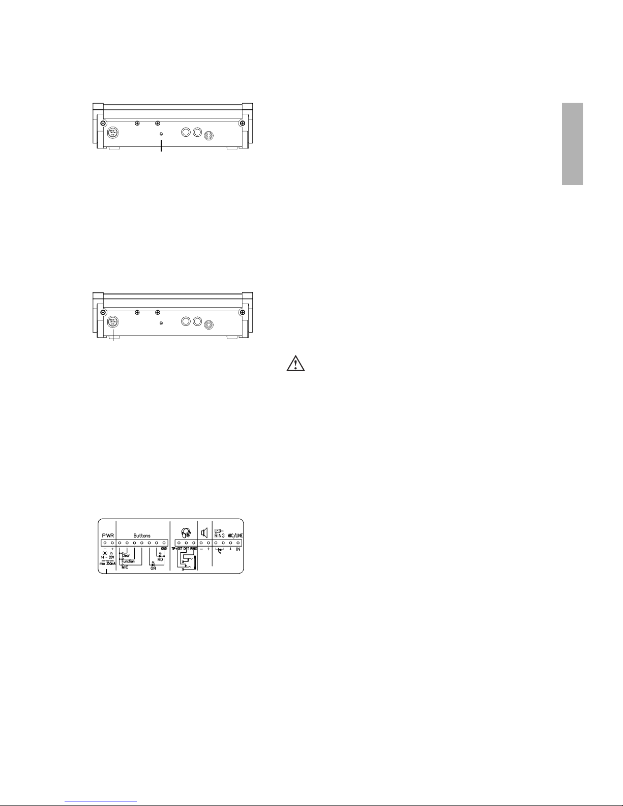
3.6 Speisung MCW-D 2673
• Die MCW-D 2673 Systemanschlusseinheit wird über eine DC-Spannung
(zwischen 14 und 20 V), die an der Klemmleiste (1) anliegt, gespeist.
(1)
• Die Sprechstellen haben einen integrierten Akku (außer Versionen
MCW-D 2xxx DC), der eine Betriebszeit von ca. 9 Stunden im Konferenzbetrieb gewährleistet.
• Bei nachlassender Spannung, blinkt die Betriebskontroll-LED (2) auf
der Rückseite der Sprechstelle.
• Die Restbetriebszeit beträgt, je nach Konfiguration mit der MCW-D 200
Editor Software, ca. eine halbe Stunde oder 1 Stunde.
• Die nachlassende Akkuspannung wird zusätzlich über die Steuerzentrale MCW-D 200 an der RS 232 oder LAN-Schnittstelle signalisiert
und kann von einer externen Mediensteuerung ausgewertet werden.
(2)
3.4 Speisung/Betriebszeit
Rückseite Sprechstelle
• Die MCW-D Sprechstellen (außer Versionen MCW-D 2xxx DC) können
auch über das externe DC-Netzteil CA 2455 gespeist werden, welches
Sie an die Multifunktionsbuchse (1) auf der Rückseite der jeweiligen
Sprechstelle anschließen.
• Soll ein anderes Netzteil angeschlossen werden, so sollte die
DC-Spannung 18 V DC sein (±0,5 V), Strom max. 180 mA,
Restwelligkeit < 20 mV AC.
(1)
3.5 Speisung über externes
Netzteil CA 2455
Rückseite Sprechstelle
Wichtig:
• Das Netzteil darf nur bei ausgeschalteter Sprechstelle ein-
und ausgesteckt werden.
• Wenn Sie die Sprechstelle zuerst über die externe DC-Speisung
betreiben und dann die DC-Speisung abschalten, wird die
Sprechstelle über den eingebauten Akku gespeist, bis dieser
fast leer ist. Zur Vermeidung einer Tiefentladung des Akkus
schaltet sich die Sprechstelle selbsttätig ab.
• Die Speisung über das externe Netzteil CA 2455 erfolgt nicht
automatisch beim Anschluss des Netzteils. Die Sprechstelle
muss nach Anschluss des Netzteils eingeschaltet werden.
Page 22
22
• Durch Drücken der Mikrofontaste (8) an der Delegiertensprechstelle
wird eine Anmeldung im System registriert.
• Die Zuteilung erfolgt über die Präsidentensprechstelle mit der
Funktionstaste (10) in der Reihenfolge der Anmeldung. Die Funktionstaste und die Betriebsart Anmeldung müssen jedoch zuvor mit der
MCW-D 200 Editor Software konfiguriert werden. Siehe hierzu auch
die entsprechende Bedienungsanleitung.
• Die LED (7) bzw. (3) der Delegiertensprechstelle leuchtet rot, um die
Anmeldung zu signalisieren.
• Ein erneutes Drücken der Mikrofontaste (8) löscht die Anmeldung. Die
LED (7) bzw. (3) geht aus.
• Der Präsident kann die Anmeldeliste durch Drücken der Clear-Taste (9)
löschen.
3.8 Anmeldebetrieb ohne externen PC oder Steuerung
(8) (10)
Delegierter Präsident
(7)
(9)
• Schalten Sie das Schwanenhalsmikrofon mit der Mikrofontaste (8) ein.
• Roter Leuchtring am
Schwanenhalsmikrofon leuchtet
und LED (7) bzw. (3) leuchtet grün: Das Mikrofon ist sprechbereit
• Mit der Standardausführung der Steuerzentrale MCW-D 200 können
4 Teilnehmer (z.B. 3 Delegierte und 1 Präsident) gleichzeitig sprechen.
Mit der entsprechenden Erweiterung in der MCW-D 200 können bis zu
7 Teilnehmer (z.B. bis zu 6 Delegierte und ein Präsident) gleichzeitig
sprechen.
3.7 Betriebsart Manuell
(8) (8)
Delegierter Präsident
(7) (7)
Wichtig:
• Sollte die maximale Anzahl der gleichzeitig aktivierten
Sprechstellen erreicht sein, kann das Mikrofon erst dann
manuell eingeschaltet werden, wenn eine andere
Sprechstelle ausgeschaltet wurde.
(3)
MCW-D 2673
(3)
MCW-D 2673
Page 23
23
deutsch
• An den Dokumentationsausgang (4) kann ein Recorder zur Aufzeichnung der Konferenz angeschlossen werden.
• Die Lautstärke kann über einen PC mit der MCW-D 200 Editor-Software
eingestellt werden.
• An den Dokumentationsausgang (4) kann auch ein Kopfhörer angeschlossen werden. Wir empfehlen eine Mindestimpedanz von 30 Ω.
3.9 Aufzeichnen der Konferenz
(4)
3.10 Pflege der MCW-D Sprechstellen
• Zum Reinigen der MCW-D Sprechstellen bei leichten Verschmutzungen wie Fingerabdrücke, Staub, Marmelade oder
Fruchtsaft nehmen Sie ein feuchtes Tuch, Schwamm oder Bürste und einen flüssigen Haushaltsreiniger.
• Vor der Reinigung muss die Fläche gründlich angefeuchtet werden. Zum Schluss mit einem feuchten Tuch abwischen.
• Achten Sie darauf, dass kein Wasser in die Mikrofonkapsel oder in das Gehäuse läuft.
• Bei Verschmutzungen durch Mineralöle und -fette sowie tierische und pflanzliche Fette können Sie Spiritus, Isopropylalkohol
oder Reinigungsbenzin verwenden.
• Verschmutzungen durch Kugelschreiber, Farbband oder Kohlepapier behandeln Sie am besten mit Isopropylalkohol oder
Spiritus.
• Die Ladekontakte reinigen Sie von Zeit zu Zeit mit Spiritus oder Isopropylalkohol
• Den Poppschutz reinigen Sie am besten mit klarem, warmen Wasser. Achten Sie darauf, dass der Poppschutz vollkommen
trocken ist, bevor sie ihn wieder auf das Mikrofon aufsetzen.
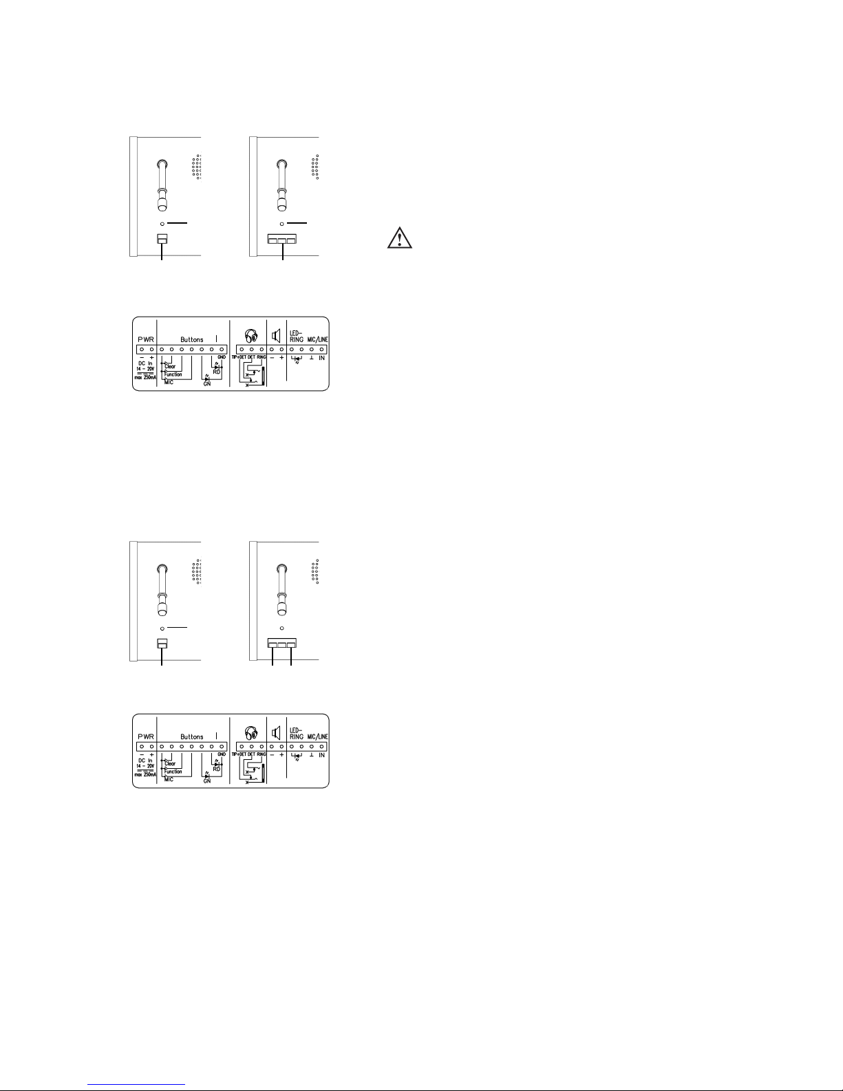
Wichtig:
• Werden die 3 Pins für die Kopfhörerbuchse nicht benutzt, müssen die Pins „TIP+DET“ und „DET“ gebrückt werden, da sonst
die Sprechstelle unter Umständen so reagiert, als ob ein
Kopfhörer angeschlossen wäre und auf dem falschen Kanal
empfängt (LED und Leuchtring blinken rot).
(2)
• An die Klemmleiste 2 mit dem Kopfhörer-Symbol kann ein Recorder
zur Aufzeichnung der Konferenz angeschlossen werden. Die Lautstärke
kann über PC mit der MCW-D 200 Editor-Software eingestellt werden.
• An die Klemmleiste 2 kann statt einem Recorder ein Kopfhörer mit
einer Mindestimpedanz von 30 Ω angeschlossen werden.
MCW-D 2673
Page 24
24
4.1 Sicherheitscode
Mit der Software MCW-D 200 Editor kann den MCW-D Sprechstellen und der Steuerzentrale MCW-D 200 innerhalb eines
Systems ein Sicherheitscode vergeben werden. Das System wird somit noch abhörsicherer.
4. Programmierbare Sprechstellenfunktionen mit MCW-D 200 Editor Software
Die nachfolgend aufgeführten Sprechstellenfunktionen sind nur dann verfügbar, wenn sie zuvor mit der Software
MCW-D 200 Editor programmiert wurden. Genaue Beschreibung siehe in der entsprechenden Bedienungsanleitung MCW-D 200
Editor Software.
Die Funktionstaste (10) hat je nach Konfiguration eine der fol-
genden Funktionen: Mute, Löschen oder Priorität. Die Funktionstaste
kann entweder mit einem an der Präsidentensprechstelle angeschlossenem Programmiergerät oder drahtlos über die Steuereinheit mit der
MCW-D 200 Editor-Software konfiguriert werden.
1. Priorität
Alle aktiven Delegiertensprechstellen werden gelöscht und das
Mikrofon der Präsidentensprechstelle wird eingeschaltet. Die
Delegierten können ihr Mikrofon anschließend wieder einschalten.
(= Werkseinstellung)
2. Mute
Alle aktiven Delegiertensprechstellen werden vorübergehend
stummgeschaltet, wenn der Präsident spricht. Sobald der Präsident
sein Mikrofon wieder ausschaltet, werden die vorher aktiven
Delegiertensprechstellen wieder aktiviert.
3. Löschen
Alle aktiven Delegiertensprechstellen werden gelöscht und können
ihr Mikrofon nicht einschalten, solange der Präsident spricht.
4. Funktion
Über die RS 232 Schnittstelle wird von der Steuerzentrale MCW-D 200
ein Befehl gesendet, der z.B. in Verbindung mit einer Mediensteuerung eine programmierte Funktion ausführt (z.B. Licht ein/aus).
Gleichzeitig wird auch bei den anderen Funktionen ein Befehl über
die RS 232 Schnittstelle von der Steuerzentrale MCW-D 200 gesendet.
5. Stummschalten eines externen AUX-IN-Anschlusses
Mit dem ersten Drücken der Funktionstaste wird der Anschluss
stummgeschaltet, beim zweiten Drücken der Funktionstaste wird die
Stummschaltung aufgehoben, beim dritten Drücken wird der
Anschluss wieder stummgeschaltet usw.
6. Zwei verschiedene Befehle je nachdem wie lange die
Funktionstaste gedrückt wird
< 1 Sekunde = Befehl A wird generiert
> 1 Sekunde = Befehl B wird generiert
7. Zuteilung im Anmeldebetrieb
Im Anmeldebetrieb wird die nächste Sprechstelle in der internen
Anmeldeliste zugeteilt.
8. Stummschalten des symmetr. AUX-IN-Anschlusses und Löschen
aller aktiven Delegiertensprechstellen
4.2 Auto-Off-Funktion
Die Delegiertensprechstellen haben eine sogenannte Auto-Off-Funktion, d.h. wenn eine Sprechstelle länger als z.B. 20
Sekunden nicht besprochen wird, schaltet sie sich automatisch aus. Die Auto-Off-Funktion ist werkseitig deaktiviert. Über das
Programmiergerät oder PC mit der Editor-Software kann die Ansprechschwelle und Zeit eingestellt werden. Der Leuchtring am
Schwanenhalsmikrofon blinkt 5 Sekunden bevor die Sprechstelle sich abschaltet.
(10)
4.3 Programmierbare Funktionstaste Präsidentensprechstelle MCW-D 2013 / 2023 / 2073
MCW-D 2013 / 2023 / 2073
(10)
MCW-D 2673
Page 25
25
deutsch
4.5 Override-Betrieb
Arbeiten die Sprechstellen im Override-Betrieb, wird die zuerst eingeschaltete Sprechstelle beim Zuschalten einer weite-
ren Sprechstelle ausgeschaltet, wenn die Anzahl der maximal offenen Mikrofone (NOM) überschritten wird.
Arbeiten die Sprechstellen im Push-To-Talk-Betrieb (PTT), muss
die Mikrofontaste (8) solange gedrückt werden, wie der Sprecher ins
Mikrofon spricht.
Diese Konfiguration empfiehlt sich zum Beispiel dann, wenn kurz in die
Konferenz zwischengerufen werden soll.
Wenn Sie die Sprechstellen MCW-D 2071 und 2073 oder MCW-D 2673
mit der Bedieneinheit CA 2473-2 einsetzen, können Sie Abstimmungen
durchführen. Zum Abstimmen dienen die 3 Tasten (12) unterhalb des
Displays (11).
Genaue Beschreibung siehe in der entsprechenden Bedienungsanleitung
MCW-D 200 Voting Software.
(11)
(12)
4.4 Abstimmung
4.6 Push-To-Talk-Betrieb
(8) (8)
Delegierter Präsident
Ja Enth. Nein
Programmierbare Sprechstellenfunktionen mit MCW-D 200 Editor Software
4.7 Automatik-Betrieb
Arbeiten die Sprechstellen im Automatikbetrieb, werden die Sprechstellen sprachgesteuert eingeschaltet. Das heißt
sobald in das Mikrofon gesprochen wird, schaltet sich die Sprechstelle ein. Die Mikrofontaste wird in diesem Fall nicht bedient.
Wichtig:
• Dies gilt nur für Sprechstellen, die im Override-Betrieb arbeiten. Andere werden davon nicht beeinflußt.
Wichtig:
• Die Ansprechschwelle kann mit der MCW-D 200 Editor Software für jede Sprechstelle einzeln konfiguriert werden.
Ebenso die Auto-Off-Zeit.
Page 26
26
4.9 Zoning-Funktion
• Bei Dolmetschanwendungen oder einer separaten Beschallung von Saal und Podium empfiehlt sich die Funktion Zoning.
• Bei dieser Funktion können bestimmte Sprechstellen, deren Konfiguration sich von den anderen Sprechstellen unterscheidet,
auf einen bestimmten Ausgang der optional erhältlichen Platine CA 2451 gelegt werden.
• Mit der MCW-D 200 Editor Software können an alle oder einzelne
Teilnehmer Nachrichten gesendet werden.
• Die Nachrichten werden unmittelbar nach dem Senden im Display
(11) der Sprechstellen MCW-D 2071/2073 oder MCW-D 2673 mit
Bedieneinheit CA 2473-2 angezeigt.
(11)
4.10 Empfangen von Nachrichten
Bitte abstimmen
Programmierbare Sprechstellenfunktionen mit MCW-D 200 Editor Software
• Diese Betriebsart funktioniert nur in Verbindung mit einem Bedien-PC
und der MCW-D Controller-Software oder einem Mediensteuersystem
(AMX/Panja®, Crestron®etc.) oder mit einer Präsidentensprechstelle
mit Display.
• Durch Drücken der Mikrofontaste (8) an der Sprechstelle wird eine
Anmeldung im System registriert.
• Die Zuteilung erfolgt durch den Bediener am PC oder Touchscreen der
Mediensteuerung.
• Die LED (7) leuchtet rot um die Anmeldung zu signalisieren.
• Ein erneutes Drücken der Mikrofontaste (8) löscht die Anmeldung. Die
LED (7) geht aus.
4.8 Betriebsart Anmeldung
(8)
Delegierter
(7)
Page 27
27
deutsch
5. Ladegerät LE-D 10 im Koffer MCW-D 10
Mit dem im Transportkoffer MCW-D 10 integriertem Ladegerät LE-D 10 können bis zu 10 Sprechstellenakkus gleichzeitig
geladen werden. Der Ladezustand ist von außen sichtbar.
Der Transportkoffer MCW-D 10 kann jederzeit um weitere Ladeeinheiten LE-D 10 für jeweils 10 Sprechstellen erweitert werden.
5.1 Erstinbetriebnahme
Alle Sprechstellen sollten mindestens 2 komplette Ladezyklen durchlaufen (laden und entladen), damit eine 100%ige
Betriebskapazität der Akkus in den Sprechstellen gewährleistet ist. Ein Akku erreicht erst nach mehrmaligem Auf- und Entladen seine
volle Kapazität.
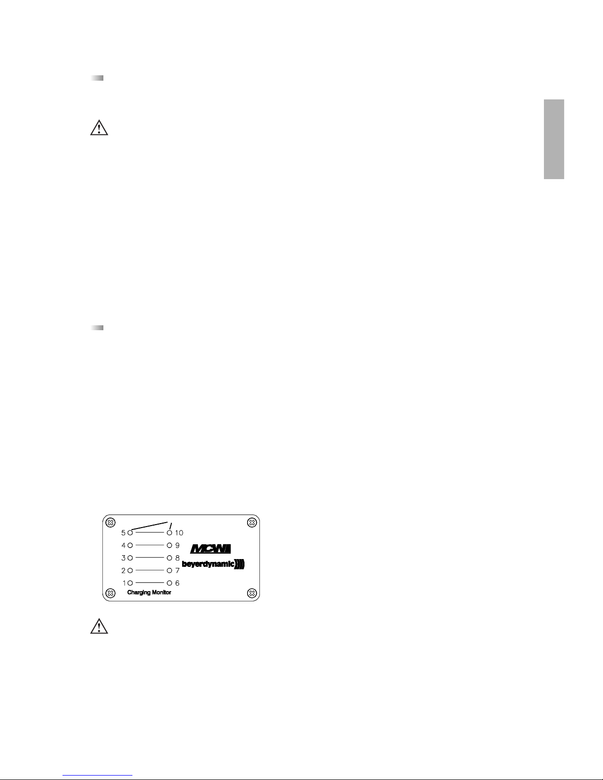
5.2 Ladevorgang
1. Schließen Sie das Ladegerät ans Netz an und schalten Sie es mit dem Ein-/Ausschalter ein. Der Schalter leuchtet.
2. Schieben Sie die ausgeschalteten Sprechstellen in die Ladefächer. Eventuell noch eingeschaltete Sprechstellen werden automatisch ausgeschaltet. Werden die Sprechstellen wieder dem Ladefach entnommen, müssen sie von Hand eingeschaltet werden.
3. Der Ladevorgang wird durch die grüne LED von außen angezeigt.
Jedem Ladefach ist eine LED (1 bis 10) zugeordnet.
a) ___ ___ ___ __ LED blinkt langsam: Akku wird geladen
b) _________________ LED leuchtet dauerhaft: Akku voll
c) - - - - - - - - - - - - - - LED blinkt schnell: Fehlermeldung
d) LED ist aus: keine Sprechstelle im Ladefach bzw. kein Kontakt
e) . . . . . . . . LED blitzen rhythmisch schnell: Formiermodus
f) . - . - . - . - . - . - . - . LED blitzt und blinkt: Laden im Formiermodus
LED
Sicherheitsinformationen
• Das Gerät muss so aufgestellt werden, dass die Steckverbindung leicht zugänglich ist.
• Das Gerät muss an eine Netz-Steckdose mit Schutzkontakt angeschlossen werden.
• Setzen Sie das Gerät niemals Regen oder hoher Feuchtigkeit aus. Installieren Sie es daher nicht in unmittelbarer Nähe
von Swimming Pools, Duschanlagen, feuchten Kellerräumen oder sonstigen Bereichen mit außergewöhnlich hoher
Luftfeuchtigkeit.
• Stellen Sie niemals mit Flüssigkeiten gefüllte Gegenstände (z.B. Vasen oder Trinkgläser) auf das Gerät.
• Installieren und betreiben Sie das Gerät auch niemals in unmittelbarer Nähe von Heizkörpern, Beleuchtungsanlagen
oder anderen wärmeerzeugenden Geräten.
• Verlegen Sie alle Kabel stets so, dass sie nicht durch scharfe Gegenstände geknickt oder gar durchgetrennt werden
können.
• Überprüfen Sie, ob die Anschlusswerte mit der vorhandenen Netzstromversorgung übereinstimmen. Bei Anschluss des
Systems an die falsche Stromversorgung können ernsthafte Schäden entstehen.
• Dieses Gerät benötigt eine ausreichende Ventilation. Decken Sie die Lüftungsöffnungen nicht ab. Achten Sie auf einen
Mindestabstand von 20 cm rund um das Gerät.
• Stellen Sie niemals offene Brandquellen (z.B. Kerzen) auf das Gerät.
• Entfernen Sie auf keinen Fall den Schaumstoff aus dem Ladegerät LE-D 10. Im Inneren des Ladegerätes befinden sich
keine wartungsfähigen Teile.
Hinweis
• Liegt eine Fehlermeldung vor, versuchen Sie den Ladevorgang noch einmal durchzuführen. Sollten die LEDs noch immer
schnell blinken, setzen Sie sich bitte mit Ihrer beyerdynamic-Vertretung in Verbindung.
• Die Ladedauer beträgt bei vollständig entleertem Akkus max. 2 Stunden.
• Es ist normal, dass sich Akkus während des Ladevorgangs etwas aufheizen.
• Zum Reinigen der Ladekontakte verwenden Sie Spiritus oder Isopropylalkohol.
Page 28
28
Die MCW-D Sprechstellen können auch über das externe
Ladegerät CA 2456 geladen werden, welches Sie an die Multifunktionsbuchse (1) anschließen.
5.3 Formierung
Die Ladeeinheiten LE-D 10 sind mit einem Formier-Modus für die Sprechstellenakkus ausgestattet. Die Akkus werden
werkseitig formiert und geladen ausgeliefert. Falls die Sprechstellen mehrere Monate nicht genutzt wurden, empfehlen wir, vor
Inbetriebnahme die Akkus zu formieren, d.h. die Ladekurve wieder in Idealzustand zu bringen. Gehen Sie wie nachfolgend
beschrieben vor:
• Nehmen Sie zuerst alle Sprechstellen aus den Ladefächern heraus.
• Drücken Sie nach dem Einschalten des Netzschalters kurz auf die im Boden der beiden äußersten Ladefächer angebrachten
Taster (in einer runden Aussparung neben den Kontaktstiften).
• Beim Drücken je eines Tasters wird der Formiermodus in den zugehörigen 5 Ladefächern aktiviert. Die LEDs blitzen rhythmisch
schnell.
• Schieben Sie dann die Sprechstellen in das Ladegerät. Die LED blitzt und blinkt.
• Sobald die grüne LED dauerhaft leuchtet, ist der Ladevorgang beendet.
6. Akkuladung über externes Ladegerät CA 2456
(1)
Rückseite
Wichtig:
• Die automatische Abschaltung der Sprechstellen im Ladebetrieb ist beim CA 2456 funktionsbedingt nicht aktiv. Deshalb
müssen die Sprechstellen vor dem Laden manuell (oder über
die MCW-D 200 Steuerzentrale) abgeschaltet werden.
• Es ist normal, dass sich Akkus während des Ladevorgangs
etwas aufheizen.
• Die Ladedauer beträgt bei vollständig entleertem Akku 4
Stunden.
Achtung:
Es dürfen nur leere Akkus formiert werden - keine vollen! Schalten Sie das Gerät während des Formier-Modus nicht aus
bzw. nehmen Sie es nicht vom Stromnetz, da sonst der Formier-Modus unterbrochen wird.
Der Formier-Modus wird automatisch verlassen, wenn die Sprechstellen als voll geladen erkannt werden oder wenn das
Ladegerät ausgeschaltet wird.
LED-Anzeigen
Rote LED (3) leuchtet: • Ladevorgang des Akkus
Grüne LED (4) leuchtet: • Akku ist geladen,
Impuls-Erhaltungsladung
Rote LED (3) blinkt: • Testphase (ca. 10 Sekunden)
• Akku defekt
• Entladevorgang nach Drücken der
Entladetaste (2)
Ladevorgang
• Der Ladevorgang beginnt automatisch, sobald das Ladegerät an der Sprechstelle und am Netz angeschlossen ist.
• Nach Ablauf der Testphase (rote LED blinkt ca. 10 Sekunden) erfolgt die Aufladung (rote LED (3) leuchtet konstant). Sollte die
rote LED (3) weiter blinken, ist entweder der Akku defekt oder es wurde ein Entladevorgang gestartet.
• Nach erfolgter Aufladung schaltet das Gerät automatisch auf Impuls-Erhaltungsladung (grüne LED (4) leuchtet konstant; rote
LED (3) erlischt).
Entladung
• Soll der Akku vor dem Ladevorgang entladen werden, starten Sie den Entladevorgang durch Drücken (ca. 2 Sekunden) der
Entladetaste (2). Die Entladung sollte jedoch erst nach Ablauf der Testphase erfolgen.
• Nach erfolgter Entladung, welche im Einzelfall mehrere Stunden dauern kann, schaltet das Gerät automatisch auf den
Ladevorgang um.
Ladegerät CA 2456
(3)
(4)
(2)
Page 29
Lösung
• Schalten Sie die Steuerzentrale ein
• Verringern Sie den Abstand zwischen Steuerzentrale und
Sprechstellen
• Überprüfen Sie die Kanaleinstellungen mit der MCW-D Editor
Software
• Laden Sie die Sprechstelle wieder
auf
• Falls der Akku leer ist, laden Sie die
Sprechstelle wieder auf
• PIN Code deaktivieren
• Wenn möglich erhöhen Sie die
NOM
• Verringern Sie den Abstand zwischen Steuerzentrale und
Sprechstellen
• Verwenden Sie die in der
Bedienungsanleitung MCW-D
Editor genannten
Standardeinstellungen
• Schalten Sie die Steuerzentrale ein
• Wenn möglich erhöhen Sie die
NOM
• Falls der Akku leer ist, laden Sie die
Sprechstelle wieder auf
• Verringern Sie den Abstand zwischen Steuerzentrale und
Sprechstellen
• Entfernen Sie den Kopfhörer, falls
Sie ihn nicht benötigen
• Erhöhen Sie die Lautstärke über
die MCW-D Editor Software
• Erhöhen Sie die Lautstärke etwas
• Schalten Sie die Sprechstelle ein
• Schließen Sie den Kopfhörer richtig
an
• Erhöhen Sie die Lautstärke über
die MCW-D Editor Software
• Siehe Anschlussbild unter Kapitel
10.
• Überprüfen Sie die Einstellungen
mit der MCW-D Editor Software
• Verwenden Sie die
Standardeinstellungen:
Sprechstelle - 18 dB, Ducking -25 dB
• Korrigieren Sie die Lautstärke und
Position der Lautsprecher
Problem
LED (7) blinkt rot
Betriebskontroll-LED (2) blinkt
Sprechstelle geht aus
Zuteilung nicht möglich
Sprechstelle läßt sich nicht einschalten
Sprechstellenlautsprecher funktioniert nicht
Kopfhörerausgang funktioniert nicht
Rückkopplungen
Mögliche Ursache
• Steuerzentrale ist nicht eingeschaltet
• Reichweite ist überschritten
• Kanäle falsch konfiguriert
• Akku ist fast leer
• Akkurestzeitwarnschwelle zeigt an,
dass der Akku bald leer ist
• Überprüfen Sie den Akku, ob er
noch voll ist
• PIN Code ist aktiviert
• Überprüfen Sie die NOM
Einstellung
• Reichweite ist überschritten
• Überprüfen Sie die
Kanaleinstellungen
• Steuerzentrale ist nicht eingeschaltet
• Überprüfen Sie die NOMEinstellung
• Überprüfen Sie den Akku
• Reichweite ist überschritten
• Die Kopfhörerbuchse ist belegt
• Überprüfen Sie die
Lautstärkeeinstellung mit der
MCW-D Editor Software
• Überprüfen Sie die „Duckingeinstellung“ mit der MCW-D Editor
Software
• Sprechstelle ist nicht eingeschaltet
• Kopfhörer ist nicht richtig angeschlossen
• Überprüfen Sie die die
Lautstärkeeinstellung mit der
MCW-D Editor Software
• Überprüfen Sie die
Steckerbelegung
• Kopfhörerkanal ist nicht richtig
konfiguriert
• Überprüfen Sie den
Lautsprecherpegel mit der MCW-D
Editor Software
• Überprüfen Sie die PA
Lautsprecher
29
deutsch
7. Problemlösung
Bei auftretenden Problemen mit den Sprechstellen, die nicht in der unten aufgeführen Auflistung stehen, sollte das MCW-D 200
System mit Hilfe der Software MCW-D 200 Editor zunächst wieder auf die Standardkonfiguration eingestellt werden. Siehe hierzu die entsprechende Bedienungsanleitung.
Page 30
30
Problem
Störgeräusche
Kurze Aussetzer
Mögliche Ursache
• Überprüfen Sie den Audiopegel
• Reichweite ist überschritten
• Überprüfen Sie die
Antennenposition und
Antennenkabel
• Überprüfen Sie die
Sichtverbindung zwischen
Sprechstelle und Antenne
• Störungen durch Geräte wie
Wireless LAN
Bluetooth-Geräte
Mikrowellenherde
Lösung
• Verringern Sie den Eingangspegel
an der Steuerzentrale
• Verringern Sie den Abstand zwischen Steuerzentrale und
Sprechstellen
• Unter Umständen sollte ein
Antennensignalverstärker eingesetzt werden
• Hindernisse zwischen Sprechstellen
und Antennen beseitigen; vor die
Antennen der Steuerzentrale darf
nichts gestellt werden
• Vermeiden Sie die genannten
Geräte. Vor geplanten Einsatz sollte Rücksprache mit der
beyerdynamic-Vertretung erfolgen
8. Komponenten
MCW-D 2011 Delegiertensprechstelle ohne Lautsprecher . . . . . . . . . . . . . . . . . . . . . . . . . . . . . . . . . . . Best.-Nr. 472.719
MCW-D 2013 Präsidentensprechstelle ohne Lautsprecher . . . . . . . . . . . . . . . . . . . . . . . . . . . . . . . . . . . Best.-Nr. 472.727
MCW-D 2021 Delegiertensprechstelle mit Lautsprecher. . . . . . . . . . . . . . . . . . . . . . . . . . . . . . . . . . . . . Best.-Nr. 472.735
MCW-D 2021 DC dito, jedoch für DC-Stromversorgung im Einkabelprinzip . . . . . . . . . . . . . . . . . . . . . . . . Best.-Nr. 474.428
MCW-D 2023 Präsidentensprechstelle mit Lautsprecher. . . . . . . . . . . . . . . . . . . . . . . . . . . . . . . . . . . . . Best.-Nr. 472.743
MCW-D 2023 DC dito, jedoch für DC-Stromversorgung im Einkabelprinzip . . . . . . . . . . . . . . . . . . . . . . . . Best.-Nr. 474.436
MCW-D 2071 Delegiertensprechstelle mit Lautsprecher und Display. . . . . . . . . . . . . . . . . . . . . . . . . . . Best.-Nr. 472.751
MCW-D 2071 DC dito, jedoch für DC-Stromversorgung im Einkabelprinzip . . . . . . . . . . . . . . . . . . . . . . . . Best.-Nr. 474.444
MCW-D 2073 Präsidentensprechstelle mit Lautsprecher und Display. . . . . . . . . . . . . . . . . . . . . . . . . . . Best.-Nr. 472.778
MCW-D 2073 DC dito, jedoch für DC-Stromversorgung im Einkabelprinzip . . . . . . . . . . . . . . . . . . . . . . . . Best.-Nr. 474.452
MCW-D 2673 Systemanschlusseinheit (Delegierte und Präsident) . . . . . . . . . . . . . . . . . . . . . . . . . . . . . Best.-Nr. 473.642
MCW-D 200 Steuerzentrale. . . . . . . . . . . . . . . . . . . . . . . . . . . . . . . . . . . . . . . . . . . . . . . . . . . . . . . . . . Best.-Nr. 472.522
MCW-D 10 Lade- und Transportkoffer für bis zu 10 Sprechstellen . . . . . . . . . . . . . . . . . . . . . . . . . . . Best.-Nr. 462.691
LA 10 Leerfach für MCW-D 10 . . . . . . . . . . . . . . . . . . . . . . . . . . . . . . . . . . . . . . . . . . . . . . . . . . Best.-Nr. 458.708
LB 10 Bodenplatte für MCW-D 10 mit Rollen. . . . . . . . . . . . . . . . . . . . . . . . . . . . . . . . . . . . . . . Best.-Nr. 458.716
LD 10 Deckel für MCW-D 10 . . . . . . . . . . . . . . . . . . . . . . . . . . . . . . . . . . . . . . . . . . . . . . . . . . . . Best.-Nr. 458.686
LE-D 10 Ladeeinheit für MCW-D 10 . . . . . . . . . . . . . . . . . . . . . . . . . . . . . . . . . . . . . . . . . . . . . . . . Best.-Nr. 462.683
LM-10 19"-Montage-Etage . . . . . . . . . . . . . . . . . . . . . . . . . . . . . . . . . . . . . . . . . . . . . . . . . . . . . Best.-Nr. 551.686
9. Zubehör
Lieferumfang
1 Netzkabel
1 serielles Nullmodemkabel
MCW-D 200 EditorKonfigurationssoftware . . . . . . . . . . . . . . . . . . . . . . . . . . . . . . . . . . . . . . . . . . . . . . . . . . Best.-Nr. 472.557
Hinweis:
Die Antennen sind nicht im Lieferumfang enthalten.
Optional
CA 2411 Stab-Winkel-Antenne, 2,4 GHz, N-Anschluss . . . . . . . . . . . . . . . . . . . . . . . . . . . . . . . . . . Best.-Nr. 464.236
CA 2412 Stab-Antenne, 2,4 GHz, SMA-Anschluss . . . . . . . . . . . . . . . . . . . . . . . . . . . . . . . . . . . . . . Best.-Nr. 464.244
CA 2413 Planar-Antenne, 2,4 GHz, SMA-Anschluss. . . . . . . . . . . . . . . . . . . . . . . . . . . . . . . . . . . . . Best.-Nr. 464.252
CA 2420 Standardkabel, 2,4 GHz, Meterware, N-Anschluss . . . . . . . . . . . . . . . . . . . . . . . . . . . . . . Best.-Nr. 464.260
CA 2421 Standardkabel, 2,4 GHz, N(HF)-N(HF), 10 m . . . . . . . . . . . . . . . . . . . . . . . . . . . . . . . . . . . Best.-Nr. 464.279
CA 2422 Standardkabel, 2,4 GHz, N(HF)-N(HF), 20 m . . . . . . . . . . . . . . . . . . . . . . . . . . . . . . . . . . . Best.-Nr. 464.287
CA 2430 Dämpfungsarmes Kabel, 2,4 GHz, Meterware . . . . . . . . . . . . . . . . . . . . . . . . . . . . . . . . . Best.-Nr. 464.295
CA 2431 Dämpfungsarmes Kabel, 2,4 GHz, N(HF)-N(HF), 10 m. . . . . . . . . . . . . . . . . . . . . . . . . . . . Best.-Nr. 464.309
CA 2432 Dämpfungsarmes Kabel, 2,4 GHz, N(HF)-N(HF), 20 m. . . . . . . . . . . . . . . . . . . . . . . . . . . . Best.-Nr. 464.325
CA 2441 RT Antennen-Verstärker für Sende- und Empfangsweg, max. 6 dBm Eingangspegel
(10 dB Verstärkung), Fernspeisung 5 V über Antennenkabel. . . . . . . . . . . . . . . . . . . . . . Best.-Nr. 470.309
CA 2441 T Antennen-Verstärker für Sendeweg, max. 20 dBm Eingangspegel
(8 dB Verstärkung), Fernspeisung 5 V über Antennenkabel. . . . . . . . . . . . . . . . . . . . . . . Best.-Nr. 470.317
Page 31

31
deutsch
CA 2442 Adapter N(HF) Female - SMA Male. . . . . . . . . . . . . . . . . . . . . . . . . . . . . . . . . . . . . . . . . . Best.-Nr. 464.376
CA 2443 Adapter N(HF) Female - SMA Female . . . . . . . . . . . . . . . . . . . . . . . . . . . . . . . . . . . . . . . . Best.-Nr. 464.384
CA 2444 Adapter N(HF) Male - SMA Female. . . . . . . . . . . . . . . . . . . . . . . . . . . . . . . . . . . . . . . . . . Best.-Nr. 464.392
CA 2445 Adapter N(HF) Male - SMA Male . . . . . . . . . . . . . . . . . . . . . . . . . . . . . . . . . . . . . . . . . . . Best.-Nr. 465.151
CA 2450 Nachrüstsatz 1 Sende-/1 Empfangskanal, 2,4 GHz DSSS . . . . . . . . . . . . . . . . . . . . . . . . . . Best.-Nr. 464.899
CA 2451 Nachrüstsatz Individuell In/Out. . . . . . . . . . . . . . . . . . . . . . . . . . . . . . . . . . . . . . . . . . . . . Best.-Nr. 464.406
CA 2455 Netzteil mit Multipinstecker . . . . . . . . . . . . . . . . . . . . . . . . . . . . . . . . . . . . . . . . . . . . . . . Best.-Nr. 465.216
CA 2456 Ladeteil für Einzelladung . . . . . . . . . . . . . . . . . . . . . . . . . . . . . . . . . . . . . . . . . . . . . . . . . Best.-Nr. 465.569
CA 2461 19" Antennenanschlussfeld, 3 x N(HF) . . . . . . . . . . . . . . . . . . . . . . . . . . . . . . . . . . . . . . . Best.-Nr. 465.224
CA 2462 3/8" Antennen-Montagekit . . . . . . . . . . . . . . . . . . . . . . . . . . . . . . . . . . . . . . . . . . . . . . . Best.-Nr. 465.232
CA 2473-2 Bedieneinheit für MCW-D 2673 . . . . . . . . . . . . . . . . . . . . . . . . . . . . . . . . . . . . . . . . . . . . Best.-Nr. 473.650
MCW-D 200 Controller
Software zur Steuerung des Systems über PC. . . . . . . . . . . . . . . . . . . . . . . . . . . . . . . . . . Best.-Nr. 465.380
Page 32

32
10. Technische Daten
Allgemein
Frequenzbereich. . . . . . . . . . . . . . . . . . . . . . . . . . . . . 2400 - 2483,5 MHz (ISM-Band)
Modulationsart. . . . . . . . . . . . . . . . . . . . . . . . . . . . . . Direct Sequence Spread Spectrum DSSS, digitale Signalbearbeitung nach
eigenem Standard
Max. Anzahl der Kanäle. . . . . . . . . . . . . . . . . . . . . . . 2*8 nutzbare Duplexkanäle pro System
Signal-/Rauschverhalten . . . . . . . . . . . . . . . . . . . . . . . 80 dB typ., unbewertet (Fremdspannung)
Reichweite zwischen Sprechstelle und Zentrale. . . . . >100 m bei Sichtverbindung
Netzspannung . . . . . . . . . . . . . . . . . . . . . . . . . . . . . . 110 - 240 VAC 50/60 Hz
Zulassung . . . . . . . . . . . . . . . . . . . . . . . . . . . . . . . . . . weltweit zulassungsfreier Betrieb
Sprechstellen
Sendeleistung . . . . . . . . . . . . . . . . . . . . . . . . . . . . . . . max. 10 mW je Kanal (10 dBm)
Anschlüsse . . . . . . . . . . . . . . . . . . . . . . . . . . . . . . . . . Multi-Port Steckverbinder Typ Mini-DIN mit folgender Belegung
Pin 1 = Masse (ICP)
Pin 2 = +VDD (ICP)
Pin 3 = +VPP (ICP)
Pin 4 = RB6 (ICP)
Pin 5 = RB7 (ICP)
Pin 6 = RC3 / SDL (I2C)
Pin 7 = RC4 / SDA (I2C)
Pin 8 = +Akku (parallel zu den Ladekontakten)
Pin 9 = +Supply (Versorgung max. 180 mA)
Reset = Pin 1 + 3 gebrückt
Gehäuse = Masse
Akkuspannung . . . . . . . . . . . . . . . . . . . . . . . . . . . . . . 12 Zellen NiMH mit je 1600 mAh
Stromaufnahme . . . . . . . . . . . . . . . . . . . . . . . . . . . . . 150 - 180 mA (je nach Betriebszustand)
Externer DC-Betrieb . . . . . . . . . . . . . . . . . . . . . . . . . . 18 V DC (± 0,5 V), Restwelligkeit < 20 mV, 180 mA (bei 18 V)
Lautsprechersystem . . . . . . . . . . . . . . . . . . . . . . . . . . Breitbandiger, eingebauter Lautsprecher, sprachentzerrt
Lautstärkeabsenkung bei Mic On. . . . . . . . . . . . . . . . einstellbar, werksseitig konfiguriert auf Absenkung um 18 dB
NF-Output. . . . . . . . . . . . . . . . . . . . . . . . . . . . . . . . . . Dokumentationsausgang einstellbar, unsymm. Klinkenbuchse (3,5 mm, Stereo)
Belegung . . . . . . . . . . . . . . . . . . . . . . . . . . . . . . . . . . Spitze = NF+
Ring = NF -
Schirm = nicht belegt
Ausgangspegel . . . . . . . . . . . . . . . . . . . . . . . . . . . . . . max. 2,4 V rms im Leerlauf, Klirrfaktor < 10%
2,3 V rms an 30 Ω Last, Klirrfaktor < 10%
Mindestanschlußimpedanz. . . . . . . . . . . . . . . . . . . . . 200 Ω
Eingebauter Limiter gegen Übersprechen . . . . . . . . . nicht abschaltbar
Limitereinsatz . . . . . . . . . . . . . . . . . . . . . . . . . . . . . . . ab 106 dB SPL
Mikrofonempfindlichkeit . . . . . . . . . . . . . . . . . . . . . . 300 mV/Pa (gemessen am XLR-Ausgang MCW-D 200) ±2 dB (1 kHz)
Max. Schalldruckpegel . . . . . . . . . . . . . . . . . . . . . . . . > 120 dB SPL
Stromversorgung . . . . . . . . . . . . . . . . . . . . . . . . . . . . 14,4 V über eingebauten NiMH-Akku (12 Zellen)
Betriebszeit je nach Sprechstellentyp. . . . . . . . . . . . . mind. 8 Stunden bei Sprechbetrieb, 10 Std. „Empfangen“
Temperaturbereich. . . . . . . . . . . . . . . . . . . . . . . . . . . +10° - 40°C (bei < 90% Luftfeuchtigkeit)
Lagertemperatur . . . . . . . . . . . . . . . . . . . . . . . . . . . . -20° - 55°C (bei < 90% Luftfeuchtigkeit)
Abmessungen (ohne Mikrofon) . . . . . . . . . . . . . . . . . Länge: 190 mm
Breite: 180 mm
Höhe vorne: 15 mm
Höhe hinten: 52 mm
Page 33

33
deutsch
Systemanschlusseinheit MCW-D 2673
Frequenzbereich. . . . . . . . . . . . . . . . . . . . . . . . . . . . . 2400 - 2483,5 MHz (ISM-Band)
Max. Anzahl der Kanäle. . . . . . . . . . . . . . . . . . . . . . . 2*8 nutzbare Duplexkanäle pro System
Abgestrahlte Leistung . . . . . . . . . . . . . . . . . . . . . . . . max 10 mW je Kanal
Rauschabstand . . . . . . . . . . . . . . . . . . . . . . . . . . . . . . 70 dB typ. unbewertet
Spannungsversorgung . . . . . . . . . . . . . . . . . . . . . . . . 14 - 20 V DC-Versorgung, gesiebt
Stromaufnahme . . . . . . . . . . . . . . . . . . . . . . . . . . . . . max. 250 mA
Temperaturbereich . . . . . . . . . . . . . . . . . . . . . . . . . . + 10 - 40°C
Eingangspegel für Mikrofon . . . . . . . . . . . . . . . . . . . 10 mV rms (Werkseinstellung)
9 V DC bias
Eingangspegel für Line. . . . . . . . . . . . . . . . . . . . . . . . 1,55 V rms (umschaltbar durch internen Jumper)
Ausgangspegel Lautsprecher . . . . . . . . . . . . . . . . . . . 2 V rms an 8 Ohm
Ausgangspegel Kopfhörer . . . . . . . . . . . . . . . . . . . . . max. 2,4 V rms im Leerlauf, Klirrfaktor < 10%
2,3 V rms an 30 Ω Last, Klirrfaktor < 10%
LED-Anschluss . . . . . . . . . . . . . . . . . . . . . . . . . . . . . . . 5 V, 20 mA (vorbereitet für direkten Anschluss von Piezotaster CA 2471 mit
Duo-LED), für andere LEDs muss ein Vorwiderstand eingesetzt werden.
Antennenbuchse . . . . . . . . . . . . . . . . . . . . . . . . . . . . Typ SMB „click“
Max. Einbaumaße. . . . . . . . . . . . . . . . . . . . . . . . . . . . 162 x 42 x 153 mm
Zulassung . . . . . . . . . . . . . . . . . . . . . . . . . . . . . . . . . . weltweit zulassungsfreier Betrieb
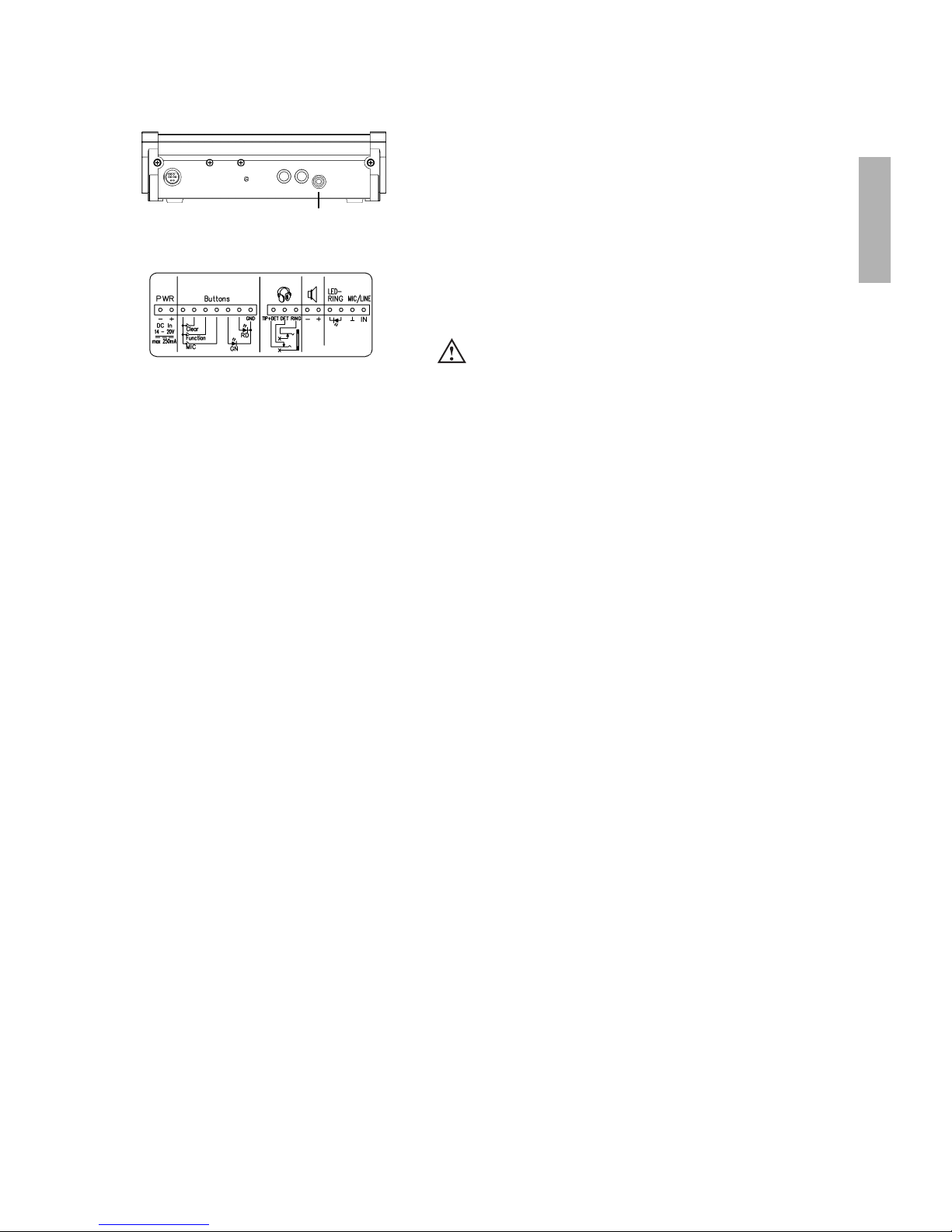
Anschluss MCW-D 2673
Page 34

34
Steuerzentrale MCW-D 200
Frequenzgang . . . . . . . . . . . . . . . . . . . . . . . . . . . . . . 70 Hz - 10 kHz (-3 dB)
Betriebsart . . . . . . . . . . . . . . . . . . . . . . . . . . . . . . . . . Antennen-Diversity auf der Empfangsseite, getrennt für jeden Kanal
Antennenanschluss. . . . . . . . . . . . . . . . . . . . . . . . . . . 3 Stück N-Steckverbinder (female)
Fernspeisespannung für Antennensignalverstärker. . 5 V, max. 2 A
Sendeleistung . . . . . . . . . . . . . . . . . . . . . . . . . . . . . . . < 10 mW je Kanal (10 dBm)
Anschlüsse
Serieller Steuerport . . . . . . . . . . . . . . . . . . . . . . . . . . RS 232, Standard mit 115 kbps, 8N1
Ethernet Port . . . . . . . . . . . . . . . . . . . . . . . . . . . . . . . IPX oder TCP/IP
Summenausgang symm.. . . . . . . . . . . . . . . . . . . . . . . XLR, +6 dBu
Summenausgang unsymm.. . . . . . . . . . . . . . . . . . . . . Cinch, Pegel regelbar (1,55 V - 300 mV Regelbereich)
Eingang symm. . . . . . . . . . . . . . . . . . . . . . . . . . . . . . . XLR, +6 dBu
Eingang unsymm. . . . . . . . . . . . . . . . . . . . . . . . . . . . . Cinch, Pegel regelbar (min. 500 mV für Vollaussteuerung)
Eingebauter Limiter gegen Übersteuerung der Eingangssignale
Anzahl der Kanäle . . . . . . . . . . . . . . . . . . . . . . . . . . . max. 7 Kanäle für Sprechstellen nutzbar
Erweiterungskarten . . . . . . . . . . . . . . . . . . . . . . . . . . CA 2450, Nachrüstsatz für einen zusätzlichen Sende- und Empfangskanal
CA 2451, symmetrische Ein- und Ausgänge (je +6dBu Nennpegel)
mit 25-pol. Sub-Steckverbinder (female)
entsprechend dem Standard «TASCAM DA Multitrack-Recorder»
Netzspannung . . . . . . . . . . . . . . . . . . . . . . . . . . . . . . 110 - 240 V AC 50/60 Hz
Netzsicherung. . . . . . . . . . . . . . . . . . . . . . . . . . . . . . . 3,15 A träge
Leistungsaufnahme . . . . . . . . . . . . . . . . . . . . . . . . . . 23 W
Temperaturbereich. . . . . . . . . . . . . . . . . . . . . . . . . . . +10° - 50°C (bei < 90% Luftfeuchtigkeit)
Anzeige . . . . . . . . . . . . . . . . . . . . . . . . . . . . . . . . . . . 8 Kanal-LEDs (rot/grün) und Power-LED (rot/grün)
Min. Rackeinbautiefe . . . . . . . . . . . . . . . . . . . . . . . . . 380 mm
Abmessungen (B x H x T) . . . . . . . . . . . . . . . . . . . . . . 19", 2HE (440 x 88 x 310 mm)
Ladegerät LE-D 10 / MCW-D 10
Max. Ladestrom . . . . . . . . . . . . . . . . . . . . . . . . . . . . . 950 mA
Stromversorgung . . . . . . . . . . . . . . . . . . . . . . . . . . . . 100 - 240 V AC ˜, 50 / 60 Hz
Ladeprinzip. . . . . . . . . . . . . . . . . . . . . . . . . . . . . . . . . softwaregesteuerte Ladekurve, variable Impulsladung,
Nachladung nach 72 Std.
Akku . . . . . . . . . . . . . . . . . . . . . . . . . . . . . . . . . . . . . . NiMH, 12 Zellen, 14,4 V, 1600 mAh
Abschaltung . . . . . . . . . . . . . . . . . . . . . . . . . . . . . . . . ∆ U-Erkennung und Sicherheitstimer
Sicherung an Netzbuchse . . . . . . . . . . . . . . . . . . . . . . Sicherungswert innen am Sicherungshalter ablesbar
Leistungsaufnahme . . . . . . . . . . . . . . . . . . . . . . . . . . 275 W (bei 1,2 A Nennstromaufnahme)
Max. Umgebungstemperatur . . . . . . . . . . . . . . . . . . . 40°C im Ladebetrieb (< 90% Luftfeuchtigkeit)
Lagertemperatur . . . . . . . . . . . . . . . . . . . . . . . . . . . . -20° - 55°C
Lüfter . . . . . . . . . . . . . . . . . . . . . . . . . . . . . . . . . . . . . schaltet sich automatisch ein
Empfohlenes Zubehör MCW-D 2673
Page 35

Ladeeinheit. . . . . . . . . . . . . . . . . . . . . . . . . . . . . . . . . 10 Sprechstellen parallel
Ladedauer. . . . . . . . . . . . . . . . . . . . . . . . . . . . . . . . . . max. 2 Stunden bei vollständig leerem Akku
Mindestladedauer im Modus „Formieren“ . . . . . . . . 30 Minuten
LED-Anzeige bei Ladevorgang des Akku:
a) ___ ___ ___ __ LED blinkt langsam: . . . . . . . . . Akku wird geladen
b) _________________ LED leuchtet dauerhaft:. . . . . . Akku voll
c) - - - - - - - - - - - - - - LED blinkt schnell: . . . . . . . . . . Fehler
d) LED ist aus: . . . . . . . . . . . . . . . . . . . . . . . . . . . . . . . keine Sprechstelle im Ladefach bzw. kein Kontakt
e) . . . . . . . . LED blitzen schnell: . . . . . . . . . Formiermodus
f) . - . - . - . - . - . - . - . LED blitzt und blinkt:. . . . . . . . Laden im Formiermodus
Abmessungen (L x B x H) . . . . . . . . . . . . . . . . . . . . . . 657 x 370 x 451 mm
Nachrüstsatz Individuell In/Out CA 2451
8 Eingänge . . . . . . . . . . . . . . . . . . . . . . . . . . . . . . . . . 25-pol. Sub-D (female) entsprechend Anschlussbelegung TASCAM-DA
Rekorder
Übertragungsbereich . . . . . . . . . . . . . . . . . . . . . . . . . 60 Hz - 10 kHz (-3 dB)
8 Ausgänge. . . . . . . . . . . . . . . . . . . . . . . . . . . . . . . . . 25-pol. Sub-D (female) entsprechend Anschlussbelegung TASCAM-DA
Rekorder
Übertragungsbereich . . . . . . . . . . . . . . . . . . . . . . . . . 60 Hz - 10 kHz (-3 dB)
Ausgangspegel . . . . . . . . . . . . . . . . . . . . . . . . . . . . . . +6 dBu für Vollaussteuerung
Eingangspegel . . . . . . . . . . . . . . . . . . . . . . . . . . . . . . +6 dBu für Vollaussteuerung (ohne Limiter); max. Eingangspegel beachten
Anschlußbelegung:
Signalfluß MCW-D 200 mit angeschlossener Erweiterungsplatine CA 2451
Funktion Pinbelegung (Hot, Cold, Schirm)
Ausgang 1 24, 12, 25 Identisch mit Master-Ausgang (XLR) standardmäßig bestückt
Ausgang 2 10, 23, 11 Erste zugeteilte Delegiertensprechstelle standardmäßig bestückt
Ausgang 3 21, 9, 22 Zweite zugeteilte Delegiertensprechstelle standardmäßig bestückt
Ausgang 4 7, 20, 8 Dritte zugeteilte Delegiertensprechstelle standardmäßig bestückt
Ausgang 5 18, 6, 19 Vierte zugeteilte Delegiertensprechstelle standardmäßig unbestückt
Ausgang 6 4, 17, 5 Fünfte zugeteilte Delegiertensprechstelle (optional) standardmäßig unbestückt
Ausgang 7 15, 3, 16 Sechste zugeteilte Delegiertensprechstelle (optional) standardmäßig unbestückt
Ausgang 8 1, 14, 2 Siebte zugeteilte Delegiertensprechstelle (optional) standardmäßig bestückt
Eingang 1 24, 12, 25 Eingang Originalsprache (Floor lang.) Individual In
Eingang 2 10, 23, 11 Eingang Fremdsprache 1 standardmäßig bestückt
Eingang 3 21, 9, 22 Eingang Fremdsprache 2 standardmäßig bestückt
Eingang 4 7, 20, 8 Eingang Fremdsprache 3 standardmäßig bestückt
Eingang 5 18, 6, 19 Eingang Fremdsprache 5 standardmäßig unbestückt
Eingang 6 4, 17, 5 Eingang Fremdsprache 6 (optional) standardmäßig unbestückt
Eingang 7 15, 3, 16 Eingang Fremdsprache 7 (optional) standardmäßig unbestückt
Eingang 8 1, 14, 2 Eingang Fremdsprache 4 (optional) standardmäßig bestückt
DC Netzteil CA 2455
Spannung . . . . . . . . . . . . . . . . . . . . . . . . . . . . . . . . . . 18 V (± 0,5 V) DC
Strombelastbarkeit . . . . . . . . . . . . . . . . . . . . . . . . . . . max. 333 mA
Eingangsspannung . . . . . . . . . . . . . . . . . . . . . . . . . . . 110 - 240 V AC 50/60 Hz
Stecker . . . . . . . . . . . . . . . . . . . . . . . . . . . . . . . . . . . . Euro-Stecker; andere Stecker auf Anfrage
Einzelladegerät CA 2456
Type . . . . . . . . . . . . . . . . . . . . . . . . . . . . . . . . . . . . . . Ansmann ACS 410 Traveller spezial
Eingangsspannung . . . . . . . . . . . . . . . . . . . . . . . . . . . 100 - 240 V AC 50/60 Hz Adapter für Europa, UK, USA und Australien
Ladestrom. . . . . . . . . . . . . . . . . . . . . . . . . . . . . . . . . . max. 650 mA (Anfangsladung mit ca. 80 mA)
Ladeüberwachung . . . . . . . . . . . . . . . . . . . . . . . . . . . ∆U-Erkennung und Sicherheitstimer
Zusatzfunktion . . . . . . . . . . . . . . . . . . . . . . . . . . . . . . Vorentladung über Taste
Anzeigen . . . . . . . . . . . . . . . . . . . . . . . . . . . . . . . . . . LED rot für Laden
LED grün für Geladen/Erhaltungsladung
Verpolung und defekter Akku werden über rotes Blinken angezeigt.
Ladedauer. . . . . . . . . . . . . . . . . . . . . . . . . . . . . . . . . . ca. 4 Stunden bei vollständig leerem Akku
35
deutsch
Page 36

36
CA 2441 RT Antennenverstärker
Frequenzbereich. . . . . . . . . . . . . . . . . . . . . . . . . . . . . 2,4 - 2,485 GHz;
mit Filter gegen GSM-Telefone
Max. Eingangspegel . . . . . . . . . . . . . . . . . . . . . . . . . . 6 dBm
Verstärkung . . . . . . . . . . . . . . . . . . . . . . . . . . . . . . . . 10 dB
Stromaufnahme . . . . . . . . . . . . . . . . . . . . . . . . . . . . . ca. 140 mA
Speisespannung . . . . . . . . . . . . . . . . . . . . . . . . . . . . . 5 V DC, Speisung erfolgt über MCW-D 100/200
Speisung über Eingang oder Ausgang
Anschluss . . . . . . . . . . . . . . . . . . . . . . . . . . . . . . . . . . 2 x N female; inkl. Adapter male/male
Abmessungen . . . . . . . . . . . . . . . . . . . . . . . . . . . . . . . Durchmesser: 26 mm
Länge: 100 mm
Gewicht . . . . . . . . . . . . . . . . . . . . . . . . . . . . . . . . . . . 166 g
CA 2441 T Antennenverstärker
Frequenzbereich. . . . . . . . . . . . . . . . . . . . . . . . . . . . . 2,4 - 2,485 GHz;
mit Filter gegen GSM-Telefone
Max. Eingangspegel . . . . . . . . . . . . . . . . . . . . . . . . . . 16 dBm
Max. Ausgangspegel . . . . . . . . . . . . . . . . . . . . . . . . . 23 dBm = 200 mW
Verstärkung . . . . . . . . . . . . . . . . . . . . . . . . . . . . . . . . 8 dB
Stromaufnahme . . . . . . . . . . . . . . . . . . . . . . . . . . . . . ca. 340 mA
Speisespannung . . . . . . . . . . . . . . . . . . . . . . . . . . . . . 5 V DC, Speisung erfolgt über MCW-D 100/200
Speisung über Eingang oder Ausgang
Anschluss . . . . . . . . . . . . . . . . . . . . . . . . . . . . . . . . . . 2 x N female; inkl. Adapter male/male
Abmessungen . . . . . . . . . . . . . . . . . . . . . . . . . . . . . . . Durchmesser: 26 mm
Länge: 100 mm
Gewicht . . . . . . . . . . . . . . . . . . . . . . . . . . . . . . . . . . . 166 g
Page 37

37
deutsch
Wichtig
Die Komponenten des MCW-Digital Systems sind in Europa gemäß Richtlinie R&TTE 99/5/EEC unter der Kennzeichnung CE 0682 !
zugelassen.
Zusätzlich besteht eine Zulassung gemäß der USA-Norm FCC.
11. Blockschaltbild Audio-Signalfluß
Page 38

38
Page 39

39
english
CONTENTS
Safety Information . . . . . . . . . . . . . . . . . . . . . . . . . . . . . . . . . . . . . . . . . . . . . . . . . . . . . . . . . . . . . . . . . Page 40
1. MCW-D 200 Control Unit . . . . . . . . . . . . . . . . . . . . . . . . . . . . . . . . . . . . . . . . . . . . . . . . . . . . . . . . Page 40
1.1 Controls and Indicators . . . . . . . . . . . . . . . . . . . . . . . . . . . . . . . . . . . . . . . . . . . . . . . . . . . Page 40
1.2 Setting up . . . . . . . . . . . . . . . . . . . . . . . . . . . . . . . . . . . . . . . . . . . . . . . . . . . . . . . . . . . . . Page 41
1.2.1 Where to place the Control Unit . . . . . . . . . . . . . . . . . . . . . . . . . . . . . . . . . . . . . . Page 41
1.2.2 How to connect the Antennae . . . . . . . . . . . . . . . . . . . . . . . . . . . . . . . . . . . . . . . . Page 41
1.2.3 Audio Connection . . . . . . . . . . . . . . . . . . . . . . . . . . . . . . . . . . . . . . . . . . . . . . . . . . Page 42
1.2.4 Power Supply . . . . . . . . . . . . . . . . . . . . . . . . . . . . . . . . . . . . . . . . . . . . . . . . . . . . . Page 42
1.2.5 How to switch the Control Unit on/off. . . . . . . . . . . . . . . . . . . . . . . . . . . . . . . . . . Page 42
1.2.6 LED Indication. . . . . . . . . . . . . . . . . . . . . . . . . . . . . . . . . . . . . . . . . . . . . . . . . . . . . Page 43
1.2.7 Rack Mounting . . . . . . . . . . . . . . . . . . . . . . . . . . . . . . . . . . . . . . . . . . . . . . . . . . . . Page 43
1.2.8 Simultaneous Operation of Media Control System and PC . . . . . . . . . . . . . . . . . . Page 43
1.3 Connecting and Positioning of remote Antennae . . . . . . . . . . . . . . . . . . . . . . . . . . . . . . Page 44
1.4 Remote Supply of the Antenna Amplifier via the Control Unit . . . . . . . . . . . . . . . . . . . . Page 45
2. Installation of optional PCBs . . . . . . . . . . . . . . . . . . . . . . . . . . . . . . . . . . . . . . . . . . . . . . . . . . . . . Page 46
2.1 How to install additional Transmitting / Receiving Channels . . . . . . . . . . . . . . . . . . . . . . Page 46
2.2 Multilingual Meetings / Interpreting Applications . . . . . . . . . . . . . . . . . . . . . . . . . . . . . . Page 49
2.3 CA 2452 Digital Inputs and Outputs AES/EBU and S-PDIF . . . . . . . . . . . . . . . . . . . . . . . . . Page 49
3. Delegate and Chairman Microphone Units . . . . . . . . . . . . . . . . . . . . . . . . . . . . . . . . . . . . . . . . . . Page 50
3.1 MCW-D 2011/2013 and MCW-D 2021/2023 Microphone Units . . . . . . . . . . . . . . . . . . . . . Page 50
3.1.1 Controls and Indicators. . . . . . . . . . . . . . . . . . . . . . . . . . . . . . . . . . . . . . . . . . . . . . Page 50
3.1.2 Switching on/off . . . . . . . . . . . . . . . . . . . . . . . . . . . . . . . . . . . . . . . . . . . . . . . . . . . Page 51
3.1.3 DC-powered MCW-D 2021 DC and MCW-D 2023 DC Versions . . . . . . . . . . . . . . . . Page 51
3.2 MCW-D 2071 and 2073 Microphone Units with Display . . . . . . . . . . . . . . . . . . . . . . . . . . Page 52
3.2.1 Controls and Indicators. . . . . . . . . . . . . . . . . . . . . . . . . . . . . . . . . . . . . . . . . . . . . . Page 52
3.2.2 Switching on/off . . . . . . . . . . . . . . . . . . . . . . . . . . . . . . . . . . . . . . . . . . . . . . . . . . . Page 53
3.2.3 DC-powered MCW-D 2071 DC and MCW-D 2073 DC Versions . . . . . . . . . . . . . . . . Page 53
3.2.4 Adjustable Functions MCW-D 2071 and MCW-D 2073 . . . . . . . . . . . . . . . . . . . . . . Page 54
3.3 MCW-D 2673 System Unit . . . . . . . . . . . . . . . . . . . . . . . . . . . . . . . . . . . . . . . . . . . . . . . . . Page 56
3.3.1 Connections . . . . . . . . . . . . . . . . . . . . . . . . . . . . . . . . . . . . . . . . . . . . . . . . . . . . . . Page 56
3.3.2 Installation . . . . . . . . . . . . . . . . . . . . . . . . . . . . . . . . . . . . . . . . . . . . . . . . . . . . . . . Page 56
3.3.3 Switching on/off . . . . . . . . . . . . . . . . . . . . . . . . . . . . . . . . . . . . . . . . . . . . . . . . . . . Page 56
3.3.4 System Units with Display . . . . . . . . . . . . . . . . . . . . . . . . . . . . . . . . . . . . . . . . . . . . Page 56
3.4 Powering/Operating Time . . . . . . . . . . . . . . . . . . . . . . . . . . . . . . . . . . . . . . . . . . . . . . . . . Page 57
3.5 Powering with external CA 2455 Power Supply Unit . . . . . . . . . . . . . . . . . . . . . . . . . . . . Page 57
3.6 Powering MCW-D 2673 . . . . . . . . . . . . . . . . . . . . . . . . . . . . . . . . . . . . . . . . . . . . . . . . . . . Page 57
3.7 Manual Operating Mode. . . . . . . . . . . . . . . . . . . . . . . . . . . . . . . . . . . . . . . . . . . . . . . . . . Page 58
3.8 Request-To-Talk Mode without external PC or Control. . . . . . . . . . . . . . . . . . . . . . . . . . . Page 58
3.9 How to record the Meeting. . . . . . . . . . . . . . . . . . . . . . . . . . . . . . . . . . . . . . . . . . . . . . . . Page 59
3.10 Maintenance of the MCW-D Microphone Units . . . . . . . . . . . . . . . . . . . . . . . . . . . . . . . . Page 59
4. Programmable Functions of the Microphone Units with the MCW-D 200 Editor Software . . . . . Page 60
4.1 Safety Code . . . . . . . . . . . . . . . . . . . . . . . . . . . . . . . . . . . . . . . . . . . . . . . . . . . . . . . . . . . . Page 60
4.2 Auto-Off-Function . . . . . . . . . . . . . . . . . . . . . . . . . . . . . . . . . . . . . . . . . . . . . . . . . . . . . . . Page 60
4.3 Function Button of the Chairman Microphone Unit . . . . . . . . . . . . . . . . . . . . . . . . . . . . . Page 60
4.4 Voting . . . . . . . . . . . . . . . . . . . . . . . . . . . . . . . . . . . . . . . . . . . . . . . . . . . . . . . . . . . . . . . . Page 61
4.5 Override Mode. . . . . . . . . . . . . . . . . . . . . . . . . . . . . . . . . . . . . . . . . . . . . . . . . . . . . . . . . . Page 61
4.6 Push-To-Talk Mode. . . . . . . . . . . . . . . . . . . . . . . . . . . . . . . . . . . . . . . . . . . . . . . . . . . . . . . Page 61
4.7 Automatic Mode . . . . . . . . . . . . . . . . . . . . . . . . . . . . . . . . . . . . . . . . . . . . . . . . . . . . . . . . Page 61
4.8 Request-to-Talk Mode . . . . . . . . . . . . . . . . . . . . . . . . . . . . . . . . . . . . . . . . . . . . . . . . . . . . Page 62
4.9 Zoning Function. . . . . . . . . . . . . . . . . . . . . . . . . . . . . . . . . . . . . . . . . . . . . . . . . . . . . . . . . Page 62
4.10 How to receive Messages. . . . . . . . . . . . . . . . . . . . . . . . . . . . . . . . . . . . . . . . . . . . . . . . . . Page 62
5. LE-D 10 Charger in MCW-D 10 Case . . . . . . . . . . . . . . . . . . . . . . . . . . . . . . . . . . . . . . . . . . . . . . . . Page 63
5.1 First Use . . . . . . . . . . . . . . . . . . . . . . . . . . . . . . . . . . . . . . . . . . . . . . . . . . . . . . . . . . . . . . . Page 63
5.2 Charging Process . . . . . . . . . . . . . . . . . . . . . . . . . . . . . . . . . . . . . . . . . . . . . . . . . . . . . . . . Page 63
5.3 Forming Mode . . . . . . . . . . . . . . . . . . . . . . . . . . . . . . . . . . . . . . . . . . . . . . . . . . . . . . . . . . Page 64
6. Battery Charging with external CA 2456 Charger . . . . . . . . . . . . . . . . . . . . . . . . . . . . . . . . . . . . . Page 64
7. Trouble Shooting . . . . . . . . . . . . . . . . . . . . . . . . . . . . . . . . . . . . . . . . . . . . . . . . . . . . . . . . . . . . . . Page 65
8. Components . . . . . . . . . . . . . . . . . . . . . . . . . . . . . . . . . . . . . . . . . . . . . . . . . . . . . . . . . . . . . . . . . . Page 66
9. Accessories . . . . . . . . . . . . . . . . . . . . . . . . . . . . . . . . . . . . . . . . . . . . . . . . . . . . . . . . . . . . . . . . . . . Page 66
10. Technical Specifications . . . . . . . . . . . . . . . . . . . . . . . . . . . . . . . . . . . . . . . . . . . . . . . . . . . . . . . . . Page 68
11. Block Diagram Audio Signal Flow Chart . . . . . . . . . . . . . . . . . . . . . . . . . . . . . . . . . . . . . . . . . . . . Page 73
EC-Declaration of Conformity . . . . . . . . . . . . . . . . . . . . . . . . . . . . . . . . . . . . . . . . . . . . . . . . . . . . . . . . . Page 110
Page 40

40
OPERATING INSTRUCTIONS MCW-D 200
Thank you for selecting the MCW-D 200 Digital wireless conference system. Please take some time to read carefully through
this manual before setting up the equipment.
This manual describes the installation and operation of the system without control and configuration via PC.
The following components are needed for the operation of a system without PC:
• MCW-D 200 control unit
• MCW-D 2011, 2021 or 2071 delegate microphone unit
• MCW-D 2013, 2023 or 2073 chairman microphone unit
• MCW-D 2673 system unit
For more information about the control and configuration of the MCW-D 200 system via PC please refer to the MCW-D 200 Editor
manual.
1. MCW-D 200 Control Unit
The MCW-D 200 control unit is the heart of the system. It controls the delegate and chairman microphone units. With the
appropriate PCB’s more transmitting and receiving channels or interpreting applications are available.
1.1 Controls and Indicators
Front view
(1) Power LED. LED is illuminated green when the unit is switched on.
(2) Standby button. When this button is pressed for more than 3 seconds all switched-on microphone units are switched off.
When this button is pressed shortly all allocated microphones are switched off.
(3) Reset. This button resets the system into the switch-on state (to press the reset button use a paper clip).
(4) LEDs to indicate the status of the receiving channels. LED is illuminated green: the channel is vacant. LED is illuminated red:
the channel is occupied. Standard configuration: Channel “Data” is used for data communication. Channel 1 to 4 for micro-
phone units, channel 5 - 7 are not fitted.
Safety Information
• When installing the unit make sure that the plugs can be accessed easily.
• The unit must be connected to an isolated ground receptacle.
• Never expose the unit to water or excessive humidity. Do not install near swimming pools, spas, in a wet basement or
in other excessively humid environments.
• Never put any objects filled with liquids (e.g. vases or drinking vessels) onto the unit.
• Do not install or use this unit near sources of high heat, such as radiators, heat registers, flood lamps, spotlights, stoves,
or other appliances.
• Always route cables running to the unit where they will not be pinched or cut by heavy or sharp objects.
• Always turn off the power to the amplifier when making input or output connections.
• Verify that the voltage rating of the unit matches that of the AC mains outlet you are to use. If you connect the unit
to the wrong voltage, you may seriously damage it.
• Do not put wires or small objects through any of the ventilation grilles. Electric shock may result.
• This unit needs a sufficient ventilation. Therefore, never cover the ventilation grilles.
• Never place burning objects (e.g. candles) onto the unit.
(1) (2) (3) (4)
Page 41

41
english
Rear view
(5)
(6)(7)(8)(9)(10)(11)(13) (12)(14)(15)(16)(17)(18)(19)(19)(19)(6)
(5) IPX network connection (RJ 45 connector)
(6) Connection for receiving antenna A/B (N-connector)
(7) Fuse
(8) On/Off-switch
(9) Mains supply
(10) Master Out, 3-pin XLR male, balanced, for the connection of external devices such as mixing consoles or sound contracting
system (+6 dBm)
(11) Aux 1 Input, 3-pin XLR female, balanced, for the connection of external sound sources or as Insert Return (+6 dBm)
(12) Connection for transmitting antenna (N-connector)
(13) Level control for Master Out, RCA
(14) Master Out, RCA, unbalanced, for the connection of external devices such as mixing consoles, sound contracting systems or
recorders (L + R)
(15) Aux 2 Input, RCA, unbalanced, for the connection of external devices such as CD-player (L + R)
(16) Level control for Aux 2 Input, RCA
(17) RS 232 port for the connection of PC or media control system (9-pin Sub-D)
As an option there are various PCBs available.
(18) CA 2451 - Analogue, individual input/output (2 x 25-pin Sub-D) for e.g. interpreting applications and for individual
transmitting/receiving signals. Refer also to chapter 2.1.
(19) CA 2452 - Digital Input/Output, AES/EBU (XLR) and S/PDIF (RCA).
1.2 Setting up
1.2.1 Where to place the Control Unit
• Place the MCW-D 200 control unit in the same room as the transmitters.
• Do not place the MCW-D 200 control unit near digitally controlled equipment.
1.2.2 How to connect the Antennae
• Connect the receiving antennae to the antenna inputs A and B (6).
For stand-alone-operation we recommend using the CA 2411 angled rod antenna.
• Connect the transmitting antenna to the antenna output (12).
For stand-alone-operation we recommend using the CA 2411 angled rod antenna.
Important:
• There must be an unobstructed path between the microphone units and the antennae. The range is around
30 m. For optimum range the surface of the table is important, wood or plastic tables are ideal, but metal tables can
cause interferences and reduce the range.
(6)(12)(6)
Page 42

42
1.2.3 Audio Connection
• Connect the XLR (10) or RCA (14) master output to the input of a mixing console/amplifier.
• Always route cables running to the unit where they will not be pinched or cut by heavy or sharp objects.
1.2.4 Power Supply
• Verify that the voltage rating of the unit matches that of the AC mains outlet you are to use. If you connect the unit to the
wrong voltage, you may seriously damage it.
• Always route cables running to the unit where they will not be pinched or cut by heavy or sharp objects.
• Connect the MCW-D 200 control unit to the mains (9). The internal power supply unit of the control unit can adjust automatically between 90 V and 240 V at 50 - 60 Hz.
(10)(14)
(9)
1.2.5 How to switch the Control Unit on/off
• Switch on the MCW-D 200 with the On/Off-switch (8) on the rear.
• During the first 15 seconds the MCW-D 200 control unit is started, the Power LED (1) is flashing green and an operation is not
yet possible.
• The Power LED (1) on the front will illuminate green, when the control unit is ready for operation.
Rear
Front
(1)(8)
• CAUTION: Always turn off the power when making input or output connections.
Page 43

43
english
1.2.6 LED Indication
• Depending on the configuration of the MCW-D 200 control unit 5 or more channel-LEDs (4) will illuminate green
(standard: 5 channels).
(4)
1.2.7 Rack Mounting
• When mounting the MCW-D 200 control unit into a 19"-rack housing leave 1 HU for a ventilation panel above and
under the control unit.
1.2.8 Simultaneous Operation of Media Control System and PC
• If you want to operate a media control system and a PC simultaneously, connect the PC to the IPX network connection (5) and
the media control system to the RS 232 connection (17).
• For the connection to the IPX network connection use a crossover cable.
• The IPX adjustments are explained in the protocol.
(5)
(17)
Important:
• If less than 5 LEDs are illuminated, it might be that individual channels have been switched off with the MCW-D 200
Editor Software.
Page 44

44
1.3 Connecting and Positioning of remote Antennae
The MCW-D 200 control unit can also be operated with remote antennae. Low attenuation connecting cables are available
in different lengths. Please note that all three antennae have to be connected remotely. The transmitting antenna should be
mounted in the centre and the receiving antennae on the left and right. The range can be increased by using a directional antenna
(e.g. CA 2413, gain approx. 6 dB).
Depending on the cable attenuation you should use antenna amplifiers if the cables are long.
• Size of the room: up to 400 m2 (20 x 20)
• Number of participants: 30 - 100
• Antenna position: The antennae should be placed as high as possible above the table
in a position close to the participants.
• Alignment: Place the antennae so that they point to the participants (the convex side must point to the front).
Aircell 7
Standard
CA 2420
max. 20 m
= 1 x CA 2422
or 2 x CA 2421
25 mm
Cable type
Max. cable length
Min. bending radius
Ercoflex 10
Low Attenuation
CA 2430
max. 40 m
40 mm
Installation with remote antennae for normal Meetings
The CA 2413 planar antenna is connected to the MCW-D 200 control unit and mounted onto a stand with the CA 2462 mounting
kit For more information refer to the “MCW-D Design Guide”.
(1) MCW-D 200 control unit
(2) CA 2421/2422 or
CA 2431/2432 antenna cable
(3) CA 2413 planar antenna
(4) CA 2462 mounting kit 3/8"
(5) ST 600 stand 3/8"
see RX A
Important:
• There must be an unobstructed path between the microphone units and the antennae. The range is around
30 m. For optimum range the surface of the table is important, wood or plastic tables are ideal, but metal tables can
cause interferences and reduce the range.
Page 45

45
english
Cable attenuation of different cables in 2.4 GHz applications
We recommend to use the CA 2441 antenna amplifier if the cable attenuation exceeds 12 or 15 dB, i.e. if the CA 2420 cable is
longer than 40 m or the CA 2430 cable is longer than 60 m.
Important Note:
To comply with FCC RF exposure compliance requirements, the following antenna installation and device-operating configuration
must be satisfied. Only authorized and certified beyerdynamic systems integrators may perform the installation of antennae.
There are no user serviceable parts or processes. Connect the receiving antennae to the antenna inputs (5) A and B. Connect the
transmitting antenna output (12). To maintain compliance with the FCC’s RF exposure guidelines, this transmitter and its antenna
must maintain a separation distance of least 20 centimetres from all persons.
1.4 Remote Supply of the Antenna Amplifier via the Control Unit
The antenna amplifiers can be supplied remotely via the MCW-D 200 control unit. Inside of the MCW-D 200 control unit
there is a status LED which can be seen through the ventilating louvres on the rear.
This LED will illuminate green, when the remote supply voltage is 5 V at all antenna sockets.
The LED will flash red, when there is a short-circuit at the antenna socket. In this case check the antenna cables.
The remote supply voltage of 5 V supplies the CA 2441 RT and CA 2441 T antenna amplifiers.
Cable length
100 m 50 m 30 m
RG 58 100 dB 50 dB 30 dB
RG 213 U 49 dB 24 dB 15 dB
Aircell 7, CA 2420 41 dB 20 dB 12 dB
Ecoflex 10, CA 2430 24 dB 12 dB 7 dB
not suitable
short cable
normal cable
long cable
ATTENTION:
• The CA 2441 RT and CA 2441 T antenna amplifiers may be only powered with 5 V DC.
• When you connect a CA 2441 to the TX output of the MCW-D 200 you should use a connecting cable with an
attenuation of at least 10 dB.
(1) MCW-D 200 control unit
(2) CA 2430 antenna cable with
2 x CA 2435 N(HF) plug
(3) CA 2441 RT antenna amplifier
(4) CA 2462 mounting kit 3/8"
(5) CA 2413 planar antenna
(6) ST 600 stand 3/8"
see RX A
Page 46

46
2.1 How to install additional Transmitting / Receiving Channels
When more than four participants (for ex. 3 delegates and 1 chairman or 2 delegates and 2 chairmen) are to speak at the
same time, you need more transmitting and receiving channels. Using the CA 2450 PCB you can extend the MCW-D 200 control
unit with another transmitting/receiving channel. Up to three CA 2450 PCBs can be integrated into the MCW-D 200.
As a standard 5 transmitting/receiving channels can be equipped. They are 1 data communication channel, 4 voice channels
(3 delegate and 1 chairman microphone unit can be switched on) and 5 aural channels (original sound for loudspeakers of the
microphone units and for 4 foreign language channels in interpreting applications). Refer also to drawing 2.
With the additional PCBs up to 7 voice channels and 8 aural channels are available. If the aural channels are to be used for
interpreting applications, the CA 2451 PCB must be installed (refer to chapter 2.2)!
2. Installation of optional PCBs
CA 2450
CA 2451
CA 2452
for 1 additional
transmitting/receiving
channel
for multilanguage
or interpreting
applications
for the connection of
digital sound sources
such as digital mixing
console
Important:
• Before you install the PCB, you must disconnect the MCW-D 200 control unit from the mains.
Precautions for ESD Protection
• Electronic components are at risk towards electro-static discharge (ESD). In order to avoid destruction or damages
caused by ESD the following precautions are necessary:
• People who handle components that are at risk towards ESD, should be earthed (e.g. by wearing a homogeneous
tape around the wrist).
• Choose a suitable operating area and avoid carpets and other coverings on the floor or table that can produce
static charges. The operating area should be free from objects that can preserve or produce static charges.
• Components that are at risk to ESD have to be handled carefully. Avoid rubbing over any surfaces, touching of
pins that are sticking out, and touching of printed lines. Hold a component or a module at the edges only.
• Components at risk must be transported and stored in anti-static or conductive packaging.
Page 47

47
english
Drawing 1
The PCB has to be installed as described below:
1. Unscrew the screws on top (1) and at the sides (2) of the MCW-D 200 and remove the cover.
2. Unscrew the screws of the release pin (3) and put the PCB onto a free slot (4).
3. Connect the cable of the PCB to the corresponding antenna connection. Make sure that you do not interchange the connections.
Refer also to drawing 2, e.g. TX/RX 6 are connected to TX 6 and RX 6, TX/RX 7 to TX 7 and RX 7 etc.
4. Replace the cover on the MCW-D 200 and tighten the screws. Make sure that the yellowish-green non-fused earthed conductor
cable is not removed from the cover.
5. After having installed modules the channels have to be set with the MCW-D 200 Editor Software.
Page 48

48
Drawing 2
at the top RX
at the bottom TX
PCBs installed
at 1-5 as a standard
6-8 are free for
more PCBs
Page 49

49
english
2.2 Multilingual Meetings / Interpreting Applications
For multilingual meetings or interpreting applications you must complete the MCW-D 200 control unit with the CA
2451 PCB for analogue individual inputs and outputs.
Important:
The CA 2451 PCB is installed at the factory or at a local authorized distributor in your country.
Using the CA 2451 PCB the audio signals of the individual microphone units are available separately and the individual audio
inputs can be used for the aural channels in interpreting applications (original sound and foreign languages). Depending on the
number of the installed CA 2450 PCBs (1 transmitting/receiving channel), it is possible to listen to separate audio signals of max.
7 switched on microphone units and max. 8 audio signals for the aural channels.
The pin connection corresponds to Tascam-DA-XX-Recorders. As an input cable (25-pin Sub-D, male to XLR, female) use a
standard cable of the type Tascam CU SD 303 (3 m) or Tascam CU SD 305 (5 m).
As an output cable (25-pin Sub-D, male to XLR, male) use a standard cable of the type Tascam CU SD 203 (3 m) or Tascam CU SD
205 (5 m).
2.3 CA 2452 Digital Inputs and Outputs AES/EBU and S-PDIF
This PCB is not yet available.
Important:
• The max. input level is +6 dBm; i.e. the connected device must not produce a higher signal even with loud passages.
Page 50

50
3. Delegate and Chairman Microphone Units
• At the factory each microphone unit is programmed with a different identity number so that the MCW-D 200 control unit can
control them individually.
• This number, which cannot be changed, is printed on the bottom of each microphone unit.
• When you order more microphone units later, please inform the supplier of the configuration of the control unit and the identity
numbers of the microphone units.
3.1 MCW-D 2011/2013 and MCW-D 2021/2023 Microphone Units
The MCW-D 2011/2013 and MCW-D 2021/2023 are suitable for monolingual discussions without voting.
(1) Multi-function socket (connection of external charger or
DC-supply)
(2) Operating control LED
(3) Charging contacts for MCW-D 10, LE-D 10 charger or
DC connection of DC-powered microphone units
(4) Mini stereo jack socket (3.5 mm) for the connection of recorders or
headphones (e.g. DT 1)
(5) Gooseneck microphone with illuminated ring
(6) Loudspeaker (MCW-D 2021 only!)
(7) LED to indicate the function (green / red)
(8) Microphone button
(6)
(5)
(7)
(8)
Top view MCW-D 2011/2021 delegate microphone unit
(1) (2) (3) (4)
Rear view
3.1.1 Controls and Indicators
Important:
• Remove the transportation protection (a piece of cardboard) from the charging compartment of each microphone unit
inside the MCW-D 10 charging and transport case before use. When the unit is transported again, replace the transportation
protection.
• The charging contacts (3) of the microphone units can cause damages, injuries or fire damages if they come into
contact with conductive materials such as jewelry, keys or chains. This can lead to a closed circuit and heat up the material.
• To avoid an unwanted closed circuit treat the charging contacts with care, especially when the microphone units are
carried in a bag or other containers together with metallic objects.
• To avoid overstretching and premature wear and tear, always adjust the gooseneck microphone via the
lower flexible part of the microphone and never the microphone head or rigid tube. The gooseneck can only
be bent 90° at maximum.
Page 51

51
english
(6)
(5)
(7)
(8)
(8) (8)
(9)
(10)
(5) Gooseneck microphone with illuminated ring
(6) Loudspeaker (MCW-D 2023 only!)
(7) LED to indicate the function (green / red)
(8) Microphone button
(9) Clear button for clearing the delegate microphone units
(10) Function button for optional functions (refer also to chapter 4.3)
Top view MCW-D 2013/2023 chairman microphone unit
Switching on
• The microphone units have no separate on/off switch. They are
switched on and off with the microphone button (8).
• By pressing the button briefly, the microphone unit is switched on.
The LED (7) flashes for a moment and the green LED (2) on the rear is
illuminated.
Switching off
• By pressing the button for more than 2 seconds the microphone
unit is switched off and the LED (7) will flash twice orange briefly.
• If you press the standby button (2) of the MCW-D 200 control unit for
more than 3 seconds, you switch off all switched-on MCW-D microphone units within the range of the MCW-D 200 control unit.
• Furthermore, the microphone units are switched off automatically,
when they do not receive a signal from the MCW-D 200 control unit
for more than 3 minutes.
3.1.2 Switching on / off
Delegate Unit
MCW-D 200
Chairman Unit
(7) (7)
(2)
(3)
Important:
• If the microphone unit is out of range of the MCW-D 200
control unit the LED (7) will flash red. After approx. 3 minutes
the microphone unit will switch off automatically.
• If the system should fail to operate, i.e. the microphone unit is
switched on but no sound is heard, press the reset button (3)
of the control unit. Should the system still fail to operate,
check the audio configuration with the MCW-D 200 Editor
Software. If the system still does not operate then, please
contact your beyerdynamic representative.
3.1.3 DC-powered MCW-D 2021 DC and MCW-D 2023 DC Versions
• The MCW-D 2021 DC and MCW-D 2023 DC have no integrated battery, but are DC-powered.
• The power cable is connected in a daisy chain. Connect the first microphone unit with a suitable power supply unit. Connect
the second microphone unit to the first, the third to the second and so on. For a suitable power supply unit please contact your
beyerdynamic representative.
Page 52

52
3.2 MCW-D 2071 and 2073 Microphone Units with Display
The MCW-D 2071 delegate and MCW-D 2073 chairman microphone units have been developed for interpreting applications
and operate on the same principle as the other MCW-D microphone units. In addition to the other MCW-D microphone units,
however, they are fitted with three more buttons and a display. Using these buttons you can adjust the (language) channel, headphone level, the volume of the system and the remaining operating time can be seen.
The display is illuminated. This illumination is activated when the button is pressed and will go out after around 10 seconds.
(1) Multi-function socket (connection of external charger or
DC-supply)
(2) Operating control LED
(3) Charging contacts for MCW-D 10, LE-D 10 charger or
DC connection of DC-powered microphone units
(4) Mini stereo jack socket (3.5 mm) for the connection of recorders or
headphones (e.g. DT 1)
(1) (2) (3) (4)
Rear view
(5) Gooseneck microphone with illuminated ring
(6) Loudspeaker
(7) LED to indicate the function (green / red)
(8) Microphone button
(11) LC-Display
(12) Buttons for adjustments
(6)
(5)
(7)
(8)
(11)
(12)
Top view MCW-D 2071 delegate microphone unit
3.2.1 Controls and Indicators
Important:
• Remove the transportation protection (a piece of cardboard) from the charging compartment of each microphone unit
inside the MCW-D 10 charging and transport case before use. When the unit is transported again, replace the transportation
protection.
• The charging contacts (3) of the microphone units can cause damages, injuries or fire damages if they come into
contact with conductive materials such as jewelry, keys or chains. This can lead to a closed circuit and heat up the material.
• To avoid an unwanted closed circuit treat the charging contacts (3) with care, especially when the microphone units are
carried in a bag or other containers together with metallic objects.
• To avoid overstretching and premature wear and tear, always adjust the gooseneck microphone via the
lower flexible part of the microphone and never the microphone head or rigid tube. The gooseneck can only
be bent 90° at maximum.
Page 53

53
english
(6)
(5)
(7)
(8)
(9)
(10)
(5) Gooseneck microphone with illuminated ring
(6) Loudspeaker
(7) LED to indicate the function (green / red)
(8) Microphone button
(9) Clear button for clearing the delegate microphone units
(10) Function button for optional functions (refer also to chapter 4.3)
(11) LC-Display
(12) Buttons for adjustments
Top view MCW-D 2073 chairman microphone unit
(11)
(12)
(8) (8)
Switching on
• The microphone units have no separate on/off switch. They are
switched on and off with the microphone button (8).
• By pressing the button briefly, the microphone unit is switched on.
The LED (7) flashes for a moment and the green LED (2) on the rear is
illuminated.
Switching off
• By pressing the button for more than 2 seconds the microphone
unit is switched off and the LED (7) will illuminate twice orange
briefly.
• If you press the standby button (2) of the MCW-D 200 control unit for
more than 3 seconds, you switch off all switched-on MCW-D microphone units within the range of the MCW-D 200 control unit.
• Furthermore, the microphone units are switched off automatically,
when they do not receive a signal from the control unit for more than
3 minutes.
3.2.2 Switching on / off
MCW-D 2071
MCW-D 200
MCW-D 2073
(7) (7)
(2)
(3)
Important:
• If the microphone unit is out of range of the MCW-D 200 control
unit the LED (7) will flash red. After approx. 3 minutes the
microphone unit will switch off automatically.
• If the system should fail to operate, i.e. the microphone unit is
switched on but no sound is heard, press the reset button (3)
of the control unit. Should the system still fail to operate,
check the audio configuration with the MCW-D 200 Editor
Software. If the system still does not operate then, please contact
your beyerdynamic representative.
3.2.3 DC-powered MCW-D 2071 DC and MCW-D 2073 DC Versions
• The MCW-D 2071 DC and MCW-D 2073 DC have no integrated battery, but are DC-powered.
• The power cable is connected in a daisy chain. Connect the first microphone unit with a suitable power supply unit. Connect
the second microphone unit to the first, the third to the second and so on. For a suitable power supply unit please contact your
beyerdynamic representative.
Page 54

54
The following functions are adjusted with the buttons (12)
below the display (11).
3.2.4 Adjustable Functions MCW-D 2071 and MCW-D 2073
(11)
(12)
Language Selection
Switch on the MCW-D 2071/2073 microphone unit. Press the
right and left button simultaneously for around 2 seconds.
Choose the desired language.
How to adjust the Channel / Language
The participant can listen to the desired language via a headphone connected to the microphone unit. To adjust the original
or foreign language choose the appropriate channel by pressing the left or right button.
Press the middle button to leave this menu and to access the
next menu “Level (Headphone)”.
Page 55

55
english
How to adjust the Headphone Level
Press the left or right button to adjust the headphone level.
How to adjust the Volume
(MCW-D 2073 only!)
Press the left or right button to adjust the volume of the
conference system. The volume will be changed without being
displayed. With the MCW-D 200 Editor Software you can adjust
which volume is to be changed: master, Aux or talkback channel.
Press the middle button to leave this menu and to access the next
menu “Battery”.
Press the middle button to leave this menu and to access the
next menu “Master Volume”.
Display of remaining Operating Time
In this menu you can see the remaining operating time of the
microphone unit.
Depending on the battery capacity the following operating time
will be displayed:
> 60 minutes
< 60 minutes
< 30 minutes
Page 56

56
(1) Terminal strip 1 for connection of operating voltage, buttons and LED
(2) Terminal strip 2 for connection of headphone, loudspeaker, external microphone and LED ring
(3)
(4)
(1)
(2)
3.3.1 Connections
3.3.2 Installation
1. Cut holes into the tabletop for external microphone and external button(s).
2. Install the microphone unit under the table. For fixing the CA 2472 mounting bracket is available as an option.
3. Connect the buttons, operating voltage, microphone, loudspeaker and when required the headphone to the appropriate
connections.
Note:
If the antenna is connected to the system unit directly, it must be at least 12 cm long (1 wavelength).
3.3 MCW-D 2673 System Unit
The MCW-D 2673 system unit has been developed for under table installation and in principle it works like the MCW-D 2073
or MCW-D 2071 microphone unit. With one remote microphone button the MCW-D 2673 is used as a delegate microphone unit
and with three remote buttons (microphone, clear and priority) it is used as a chairman microphone unit.
Using the CA 2473 operating unit with display and three further remote buttons the system unit can be also used for voting or
interpreting applications. With these three buttons parameters such as channel, headphone level and overall volume can be
adjusted.
The display is illuminated. This illumination is activated by pressing a remote button and will extinguish after around 10 seconds.
3.3.3 Switching on/off
The system unit is switched on and off with the connected microphone button.
3.3.4 System Units with Display
If the MCW-D 2673 system unit is completed with the CA 2473-2 operating unit, you can use the microphone unit for
voting or interpreting applications. With these additional three buttons you can adjust channel/language, headphone level and
overall volume. The function “remaining operating time” is not available for MCW-D 2673.
The display is illuminated. This illumination is activated when a button is pressed and will go out after around 10 seconds. For a
detailed description of the individual functions please refer to chapter “3.2.4 Adjustable functions MCW-D 2071 and MCW-D 2073”.
MCW-D 2673
Important:
• If the three pins are not used for the headphone socket, the pins “TIP+DET” and “DET” have to be bridged, otherwise
the microphone unit could act as if a headphone were connected and thus receive signals on a wrong channel (LED and
illuminated ring will flash red).
Page 57

57
english
• The microphone units have an integrated rechargeable battery (except
MCW-D 2xxx DC versions) allowing an operating time of at least 9 hours
in discussion mode.
• As soon as the capacity is too low for satisfactory operation, the operating
control LED (2) will flash.
• The remaining time of operation is around 30 or 60 minutes, depending
on the configuration with the MCW-D 200 Editor software.
• The decreasing battery voltage is also signaled by the MCW-D 200 control
unit at the RS 232 or LAN interface and can be evaluated by an external
media control system.
(2)
3.4 Powering / Operating Time
Rear view microphone unit
• The MCW-D microphone units (except the MCW-D 2xxx DC versions)
can be powered with the CA 2455 external power supply unit which can
be connected to the multi-function socket (1).
• If another power supply unit is to be connected, the DC-voltage
should be 18 V DC (±0.5 V), current max. 180 mA, residual hum
< 20 mV AC.
(1)
3.5 Powering with external CA 2455 Power Supply Unit
Rear view microphone unit
Important:
• Connect and disconnect the external power supply only when
the microphone unit is switched off.
• If the microphone unit is powered by the DC-power supply
first and when the power supply is switched off, the microphone unit will be powered by the integrated battery until it
is nearly empty. The microphone unit switches off automatically
to avoid an exhaustive discharge.
• The microphone unit is not powered automatically, when the
CA 2455 external power supply unit is connected to it. The
microphone unit has to be switched on after having connected
the power supply unit.
3.6 Powering MCW-D 2673
• The MCW-D 2673 system units are powered via DC voltage (between
14 and 20 V) that is connected to the terminal strip (1).
(1)
Page 58

58
• Press the microphone button (8) to switch the gooseneck microphone
on.
• Red ring of the gooseneck
microphone is illuminated
and the LED (7) or (3) is
illuminated green: The microphone is ready for talking.
• Using the standard version of the MCW-D 200 control unit 4 participants
(e.g. 3 delegates and 1 chairman) can speak simultaneously. Using
additional PCBs inside the MCW-D 200 up to 7 participants (6 delegates
and 1 chairman) can speak simultaneously.
3.7 Manual Operating Mode
(8) (8)
Delegate Chairman
(7) (7)
Important:
• If the number of open microphones is reached, a microphone can only be switched on manually when another
microphone unit has been switched off.
• The request-to-talk is registered in the system by pressing the microphone button (8) of the delegate microphone unit.
• The allocation is made with the function button (10) of the chairman
microphone unit. The function button (10) and the request-to-talk
mode have to be configured with the MCW-D 200 Editor software
before. Please refer also to the appropriate manual.
• The LED (7) or (3) of the delegate unit is illuminated to indicate the
request-to-talk.
• If you press the microphone button (8) again the request-to-talk is
cleared. The LED (7) or (3) goes out.
• The chairman can clear the request-to-talk list by pressing the “Clear”button (9).
3.8 Request-To-Talk Mode without external PC or Control
(8) (10)(9)
Delegate Chairman
(7)
(3)
MCW-D 2673
(3)
MCW-D 2673
Page 59

59
english
• For recording the meeting you can connect a recorder to the
documentation output (4).
• The volume can be adjusted with a PC using the MCW-D 200 Editor
software.
• Instead of a recorder it is also possible to connect a headphone to the
documentation output (4). We recommend a min. impedance of 30 Ω.
3.9 How to record the Meeting
(4)
3.10 Maintenance of the MCW-D Microphone Units
• For cleaning the MCW-D microphone units when they are slightly dirty (finger prints, dust, jam or juice) use a soft, damp cloth,
sponge or brush and a liquid cleaning agent.
• Before cleaning the surface it must be moistened thoroughly. Afterwards it must be cleaned with a damp cloth.
• Make sure not to allow any water to enter the unit.
• For dirt caused by mineral oils and fats, animal and vegetable fats use spirit, isopropyl alcohol or benzine.
• For dirt caused by ballpoint pens, typewriter ribbons or carbon paper use isopropyl alcohol or spirit.
• Clean the charging contacts of the microphone units with spirit or isopropyl alcohol from time to time.
• Clean the supplied pop shield with clear water. Make sure that it is completely dry before you put it on the microphone again.
Important:
• If the three pins are not used for the headphone socket, the
pins “TIP+DET” and “DET” have to be bridged, otherwise the
microphone unit could act as if a headphone were connected
and thus receive signals on a wrong channel (LED and illuminated
ring will flash red).
(2)
• For recording the meeting you can connect a recorder to the terminal
strip 2. The volume can be adjusted with a PC using the MCW-D 200
Editor software.
• Instead of a recorder you can connect a headphone to the terminal
strip 2. We recommend a min. impedance of 30 Ω.
MCW-D 2673
Page 60

60
4.1 Safety Code
Using the MCW-D 200 Editor software a safety code can be entered for the MCW-D microphone units and the MCW-D 200
control unit within one system. This will increase the safety against unauthorised listening. For a detailed description please refer
to the appropriate manual.
4. Programmable Functions of the Microphone Units with the MCW-D 200 Editor Software
The functions of the microphone units described in the following are only available, when they have been
programmed with the MCW-D 200 Editor software before. Please refer to the corresponding manual MCW-D 200 Editor
Software.
Depending on the configuration the following functions are
possible with the function button (10): mute, clear or priority. The function
button can be configured with the control unit and the MCW-D 200
Editor software.
1. Priority
All delegate microphone units will be cleared and the microphone of
the chairman unit will be switched on. The delegates can switch on
their microphones again.
2. Mute
All delegate microphone units which were activated before, will be
muted when the chairman is speaking and will be re-activated when
the chairman switches off his microphone.
3. Clear
All delegate microphone units are cleared and cannot switch on
their microphone as long as the chairman is speaking.
4. Function
A command is sent via the RS 232 serial interface from the MCW-D 200
control unit and a programmed function is carried out via a media
control system for instance (e.g. light control).
For the other functions there is also a command sent via the RS 232
serial interface from the MCW-D 200 control unit.
5. How to mute an external AUX-IN port
First push mutes the port, the next one enables it, third one mutes
again etc.
6. Two different commands according to the duration of the
push
< 1 second = command A is generated (timing must be determined
later)
> 1 second = command B is generated
7. Next Function
Next function to allocate the next microphone unit which is in the
internal request-to-speak queue.
8. Muting of balanced Aux-In port & clear all active delegates, pushing
prior button a second time will release AUX-In muting.
4.2 Auto-Off-Function
The delegate microphone units have a power saving auto-off function, i.e. if no-one speaks into the microphone for more
than 20 seconds, the microphone unit switches off automatically. The auto-off-function has been deactivated at the factory. The
response threshold and the time after which the microphone switches off (hold time) can be adjusted with a PC using the
MCW-D 200 Editor software. The illuminated ring of the gooseneck microphone will flash 5 seconds before the microphone unit
is switched off.
(10)
4.3 Function button of the MCW-D 2013 / 2023 / 2073 Chairman Microphone Unit
MCW-D 2013 / 2023 / 2073
(10)
MCW-D 2673
Page 61

61
english
4.5 Override Mode
If the microphone units operate in the Override mode, the microphone unit that was switched on first, will be switched
off, when another microphone unit is switched on and the number of open microphones (NOM) will be exceeded.
4.7 Automatic Mode
If the microphone units operate in the Automatic mode, the microphone units are switched on via voice control. That is
the microphone unit is switched on as soon as someone speaks into the microphone. In this case it is not necessary to press the
microphone button.
If the microphone units operate in the Push-To-Talk mode (PTT)
the microphone button (8) must be pressed as long as someone speaks
into the microphone.
For discussions with subsequent voting you need the MCW-D 2071
and 2073 microphone units with display or the MCW-D 2673 with the
CA 2473-2 operating unit. For voting these units have 3 buttons (12)
below the display (11).
Please refer to the corresponding manual MCW-D 200 Voting Software
for more information.
(11)
(12)
4.4 Voting
4.6 Push-To-Talk Mode
(8) (8)
Delegate Chairman
Programmable Functions of the Microphone Units with the MCW-D 200 Editor Software
Important:
• This is only for microphone units that operate in the override mode; others are not affected.
Important:
• The threshold and the auto-off time can be configured with the MCW-D 200 Editor software for each microphone unit
individually.
Page 62

62
4.9 Zoning Function
• For interpreting applications or a separate sound reinforcement of hall and panel we recommend the Zoning function.
• With this function certain microphone units can be sent to a certain output of the optional CA 2451 PCB.
4.10 How to receive Messages
• This operating mode is only possible in conjunction with a PC using
the MCW-D Controller software or media control system (AMX/Panja®,
Crestron®etc.) or a chairman microphone unit with display.
• The request-to-talk is registered in the system by pressing the microphone button (8) of the microphone unit.
• The allocation is made by the operator at the PC or touchscreen of the
media control system.
• The LED (7) is illuminated red to indicate the request-to-talk.
• If you press the microphone button again the request-to-talk is
cleared. The LED (7) goes out.
4.8 Request-to-Talk Mode
Delegate
(8)
(7)
Programmable Functions of the Microphone Units with the MCW-D 200 Editor Software
(11)
Please vote now
• With the MCW-D 200 Editor Software all or individual participants can
receive messages.
• After having sent the message, it is shown on the display (11) of the
MCW-D 2071/2073 microphone units or the MCW-D 2673 with the
CA 2473-2 operating unit.
Page 63

63
english
5. LE-D 10 Charger in MCW-D 10 Case
With the integrated LE-D 10 charger in the MCW-D 10 transport case, it is possible to charge up to 10 microphone unit
batteries. The battery state is indicated on the outside of the case.
The MCW-D 10 transport case can be extended with more LE-D 10 chargers for 10 microphone units each.
5.1 First Use
To achieve a 100% battery capacity all microphone units should have 2 complete charging cycles (charging and discharging)
at least. Only after several charging and discharging cycles the rechargeable batteries will achieve their full capacity.
5.2 Charging Process
1. Connect the charger to AC power and switch it on. The LED on the switch will illuminate.
2. Put the switched-off microphone units into the charging compartments. If microphone units are switched on, they are
switched off automatically. When the microphone units are used again, they must be switched on.
3. The charging process is indicated by the green LEDs on the outside.
a) ___ ___ ___ __ LED is flashing slowly: Battery is charged
b) _________________ LED illuminates permanently: Battery is full
c) - - - - - - - - - - - - - - LED is flashing very rapidly: Error
d) LED is off: No microphone unit is inserted into charging compartment
or has no contact
e) . . . . . . . . LED flashes rapidly: Forming mode
f) . - . - . - . - . - . - . - . LED long flash/short flash: Charging in the forming mode
Safety Information
• When installing the unit make sure that the plugs can be accessed easily.
• The unit must be connected to an isolated ground receptacle.
• Never expose the unit to water or excessive humidity. Do not install near swimming pools, spas, in a wet basement or
in other excessively humid environments.
• Never put any objects filled with liquids (e.g. vases or drinking vessels) onto the unit.
• Do not install or use this unit near sources of high heat, such as radiators, heat registers, flood lamps, spotlights, stoves,
or other appliances.
• Always route cables running to the unit where they will not be pinched or cut by heavy or sharp objects.
• Verify that the voltage rating of the unit matches that of the AC mains outlet you are to use. If you connect the unit
to the wrong voltage, you may seriously damage it.
• This unit needs a sufficient ventilation. Therefore, never cover the ventilation grilles. Leave a minimum distance of
20 cm around the unit.
• Never place burning objects (e.g. candles) onto the unit.
• Do not remove the foam material from the LE-D 10 charger. There are no parts inside the LE-D 10 charger that need
servicing.
Note
• If an error has occured, try to start the charging process once again. If the LEDs are still flashing rapidly, please contact
your beyerdynamic dealer.
• The charging time is around 2 hours when the battery is completely empty.
• It is normal that the rechargeable batteries are heated up during the charging process.
• Clean the charging contacts with spirit or isopropyl alcohol from time to time.
LED
Page 64

64
5.3 Forming Mode
The LE-D 10 charging units are equipped with a forming mode for the rechargeable batteries inside the microphone units.
The batteries are formed and charged at the factory. If you have not used the microphone units for several months, you
should form the batteries before you set up the microphone units. Do this as described in the following:
• First of all remove all microphone units from the charging compartments.
• After switching on the charger press the buttons in the bottom of the two furthest charging compartments (next to the contact
pins in the round gap).
• Pressing one of these buttons will activate the forming mode for 5 charging compartments. The LEDs will flash rapidly.
• Then put the microphone units into the charging compartments. The LEDs will flash short and long.
• When the green LEDs are permanently on, then the battery is full.
The MCW-D microphone units can be also charged with the
CA 2456 external charger which is connected to the multi-function socket
(1).
(1)
Rear view microphone unit
6. Battery Charging with external CA 2456 Charger
Caution:
Only form empty batteries, but never full batteries!
Do not switch off the charging unit during the forming mode, as this will interrupt the forming mode.
The forming mode will be terminated automatically when the microphone units are fully charged or when the charger is
switched off.
Important:
• When the microphone units are charged with the CA 2456,
they are not switched off automatically. Therefore, they must
be switched off manually (or via the MCW-D 200 control unit)
before charging.
• It is normal that the rechargeable batteries are heated up
during the charging process.
• The charging time is around 4 hours when the battery is
completely empty.
LEDs
Red LED (3) illuminates: • The battery is being charged
Green LED (4) illuminates: • The battery is fully charged, trickle
charge
Red LED (3) flashes: • Test phase (approx. 10 seconds)
• Defective battery
• The battery is discharged after pressing
the discharging button (2)
How to charge the Battery
• The charging process will start automatically as soon as the charger has been connected to the microphone unit and to the
mains.
• After the test phase (red LED flashes for about 10 seconds) the charging process is started (red LED (3) illuminates permanently).
Should the red LED (3) still flash, the battery is defective or the discharging process has been started.
• After the charging process, the charger switches automatically to trickle charge (green LED (4) will illuminate permanently; red
LED (3) is off).
How to discharge the Battery
• If the battery is to be discharged before charging, you can start the discharging process by pressing the discharging button (2)
for about 2 seconds. The discharging process, however, should be started after the test phase.
• After the discharging process, which can last in individual cases several hours, the charger automatically switches to charging.
CA 2456 Charger
(3)
(4)
(2)
Page 65

Solution
• Switch on the control unit
• Reduce the distance between
control unit and microphone units
• Check the adjusted channels with
the MCW-D Editor Software
• Recharge the battery inside the
microphone unit
• If the battery is empty recharge it
• Deactivate PIN Code
• Switch on the control unit
• If possible increase the number of
open microphones (NOM)
• Reduce the distance between
control unit and microphone units
• Use the standard adjustments
mentioned in the MCW-D Editor
manual
• Switch on the control unit
• If possible increase the number of
open microphones (NOM)
• If the battery is empty recharge it
• Reduce the distance between
control unit and microphone units
• Disconnect the headphone if you
do not need it.
• Increase the volume with the
MCW-D Editor Software
• Increase the volume a bit
• Switch on the microphone unit
• Connect the headphone properly
• Increase the volume with the
MCW-D Editor Software
• Refer to the diagramm in chapter
10.
• Check the channel with the
MCW-D Editor Software
• Use the standard adjustments:
microphone unit - 18 dB,
ducking -25 dB
• Correct the volume and position of
the loudspeaker
Possible Cause
• Control unit is not switched on
• Microphone unit is not within the
range of the control unit
• Channels have been configured
incorrectly
• Battery is almost empty
• Low battery warning to indicate
that the battery is almost empty
• Check the battery if it is still full
• PIN Code is activated
• Control unit is not switched on
• Check the number of open microphones (NOM)
• Microphone unit is not within the
range of the control unit
• Check the adjusted channels
• Control unit is not switched on
• Check the number of open microphones (NOM)
• Check the battery
• Microphone unit is not within the
range of the control unit
• The headphone socket is not
available
• Check the volume adjustment with
the MCW-D Editor Software
• Check the ducking adjustment
with the MCW-D Editor Software
• Microphone unit is not switched
on
• Headphone is not connected
correctly
• Check the volume adjustment with
the MCW-D Editor Software
• Check the pin connection
• Headphone channel is not
configured correctly
• Check the volume adjustment with
the MCW-D Editor Software
• Check the PA loudspeaker
Problem
LED (7) flashes red
Power LED (2) flashes
Microphone unit goes off
Allocation is not possible
Microphone unit cannot be switched
on
Loudspeaker of the microphone unit
does not work
Headphone output does not work
Feedback
65
english
7. Trouble Shooting
If problems occur that you do not find listed below, the MCW-D system should be adjusted to the standard configuration with the
MCW-D 200 Editor software. Please refer to the appropriate manual.
Page 66

Problem
Interferences; noise
Short drop-outs
66
Possible Cause
• Check the audio level
• Microphone unit is not within the
range of the control unit
• Check the antenna positioning and
the antenna cable
• Check the line of sight between
microphone unit and antenna
• Interferences caused by devices
such as
Wireless LAN
Bluetooth devices
Microwaves
Solution
• Reduce the input level of the
control unit
• Reduce the distance between
control unit and microphone units
• If necessary use an antenna
amplifier
• Remove obstacles between microphone units and antennae; do not
place any objects in front of the
antennae of the control unit
• Remove the devices mentioned.
Before you use the MCW-D system
in conjunction with these devices
contact your beyerdynamic
representative
8. Components
MCW-D 2011 Delegate microphone unit without loudspeaker . . . . . . . . . . . . . . . . . . . . . . . . . . . . . . . Order # 472.719
MCW-D 2013 Chairman microphone unit without loudspeaker . . . . . . . . . . . . . . . . . . . . . . . . . . . . . . Order # 472.727
MCW-D 2021 Delegate microphone unit with loudspeaker . . . . . . . . . . . . . . . . . . . . . . . . . . . . . . . . . . Order # 472.735
MCW-D 2021 DC same as above, but for DC powering in a daisy chain . . . . . . . . . . . . . . . . . . . . . . . . . . . Order # 474.428
MCW-D 2023 Chairman microphone unit with loudspeaker . . . . . . . . . . . . . . . . . . . . . . . . . . . . . . . . . Order # 472.743
MCW-D 2023 DC same as above, but for DC powering in a daisy chain . . . . . . . . . . . . . . . . . . . . . . . . . . . Order # 474.436
MCW-D 2071 Delegate microphone unit with loudspeaker and display . . . . . . . . . . . . . . . . . . . . . . . . Order # 472.751
MCW-D 2071 DC same as above, but for DC powering in a daisy chain . . . . . . . . . . . . . . . . . . . . . . . . . . . Order # 474.444
MCW-D 2073 Chairman microphone unit with loudspeaker and display. . . . . . . . . . . . . . . . . . . . . . . . Order # 472.778
MCW-D 2073 DC same as above, but for DC powering in a daisy chain . . . . . . . . . . . . . . . . . . . . . . . . . . . Order # 474.452
MCW-D 2673 System unit (delegate and chairman) . . . . . . . . . . . . . . . . . . . . . . . . . . . . . . . . . . . . . . . . Order # 473.642
MCW-D 200 Control unit. . . . . . . . . . . . . . . . . . . . . . . . . . . . . . . . . . . . . . . . . . . . . . . . . . . . . . . . . . . . Order # 472.522
MCW-D 10 Charging and transport case for 10 microphone units. . . . . . . . . . . . . . . . . . . . . . . . . . . Order # 462.691
LA 10 Empty compartment for MCW-D 10 . . . . . . . . . . . . . . . . . . . . . . . . . . . . . . . . . . . . . . . . . Order # 458.708
LB 10 Bottom for MCW-D 10 with trolley wheels . . . . . . . . . . . . . . . . . . . . . . . . . . . . . . . . . . . Order # 458.716
LD 10 Cover for MCW 10. . . . . . . . . . . . . . . . . . . . . . . . . . . . . . . . . . . . . . . . . . . . . . . . . . . . . . . Order # 458.686
LE-D 10 Charging unit for MCW-D 10 . . . . . . . . . . . . . . . . . . . . . . . . . . . . . . . . . . . . . . . . . . . . . . Order # 462.683
LM-10 Compartment for 19"-mounting . . . . . . . . . . . . . . . . . . . . . . . . . . . . . . . . . . . . . . . . . . . Order # 551.686
9. Accessories
Supplied Accessories
1 mains cable
1 serial zero modem cable
MCW-D 200 EditorConfiguration software. . . . . . . . . . . . . . . . . . . . . . . . . . . . . . . . . . . . . . . . . . . . . . . . . . . Order # 472.557
Note:
The supply does not include any antennae.
Optional Accessories
CA 2411 Angled rod antenna, 2.4 GHz, N-connection . . . . . . . . . . . . . . . . . . . . . . . . . . . . . . . . . . Order # 464.236
CA 2412 Rod antenna, 2.4 GHz, SMA-connection. . . . . . . . . . . . . . . . . . . . . . . . . . . . . . . . . . . . . . Order # 464.244
CA 2413 Planar antenna, 2.4 GHz, SMA-connection. . . . . . . . . . . . . . . . . . . . . . . . . . . . . . . . . . . . Order # 464.252
CA 2420 Standard cable, 2.4 GHz, sold per metre, N-connection . . . . . . . . . . . . . . . . . . . . . . . . . . Order # 464.260
CA 2421 Standard cable, 2.4 GHz, N(HF)-N(HF), 10 m. . . . . . . . . . . . . . . . . . . . . . . . . . . . . . . . . . . Order # 464.279
CA 2422 Standard cable, 2.4 GHz, N(HF)-N(HF), 20 m. . . . . . . . . . . . . . . . . . . . . . . . . . . . . . . . . . . Order # 464.287
CA 2430 Low attenuation cable, 2.4 GHz, sold per metre . . . . . . . . . . . . . . . . . . . . . . . . . . . . . . . Order # 464.295
CA 2431 Low attenuation cable, 2.4 GHz, N(HF)-N(HF), 10 m. . . . . . . . . . . . . . . . . . . . . . . . . . . . . Order # 464.309
CA 2432 Low attenuation cable, 2.4 GHz, N(HF)-N(HF), 20 m. . . . . . . . . . . . . . . . . . . . . . . . . . . . . Order # 464.325
CA 2441 RT Antenna amplifier for transmitting and receiving, input level max. 6 dBm (10 dB gain),
remote power supply 5 V via antenna cable . . . . . . . . . . . . . . . . . . . . . . . . . . . . . . . . . . Order # 470.309
CA 2441 T Antenna amplifier for transmitting, input level max. 20 dBm (8 dB gain),
remote power supply 5 V via antenna cable . . . . . . . . . . . . . . . . . . . . . . . . . . . . . . . . . . Order # 470.317
CA 2442 Adapter N(HF) Female - SMA Male. . . . . . . . . . . . . . . . . . . . . . . . . . . . . . . . . . . . . . . . . . Order # 464.376
CA 2443 Adapter N(HF) Female - SMA Female . . . . . . . . . . . . . . . . . . . . . . . . . . . . . . . . . . . . . . . . Order # 464.384
CA 2444 Adapter N(HF) Male - SMA Female. . . . . . . . . . . . . . . . . . . . . . . . . . . . . . . . . . . . . . . . . . Order # 464.392
CA 2445 Adapter N(HF) Male - SMA Male . . . . . . . . . . . . . . . . . . . . . . . . . . . . . . . . . . . . . . . . . . . Order # 465.151
Page 67

67
english
CA 2450 PCB 1 transmitting/1 receiving channel, 2.4 GHz DSSS . . . . . . . . . . . . . . . . . . . . . . . . . . . Order # 464.899
CA 2451 PCB Individual In/Out . . . . . . . . . . . . . . . . . . . . . . . . . . . . . . . . . . . . . . . . . . . . . . . . . . . . Order # 464.406
CA 2455 Power supply unit with multi-pin plug. . . . . . . . . . . . . . . . . . . . . . . . . . . . . . . . . . . . . . . Order # 465.216
CA 2456 Single charging unit . . . . . . . . . . . . . . . . . . . . . . . . . . . . . . . . . . . . . . . . . . . . . . . . . . . . . Order # 465.569
CA 2461 19" antenna connection panel, 3 x N(HF). . . . . . . . . . . . . . . . . . . . . . . . . . . . . . . . . . . . . Order # 465.224
CA 2462 3/8" antenna mounting kit . . . . . . . . . . . . . . . . . . . . . . . . . . . . . . . . . . . . . . . . . . . . . . . . Order # 465.232
CA 2473-2 Display and multi-function buttons for MCW-D 2673 . . . . . . . . . . . . . . . . . . . . . . . . . . . Order # 473.650
MCW-D 200 Controller
Software to control the system via PC . . . . . . . . . . . . . . . . . . . . . . . . . . . . . . . . . . . . . . . Order # 465.380
Page 68

68
10. Technical Specifications
General
Frequency range. . . . . . . . . . . . . . . . . . . . . . . . . . . . . 2400 - 2483,5 MHz (ISM-band)
Modulation. . . . . . . . . . . . . . . . . . . . . . . . . . . . . . . . . Direct Sequence Spread Spectrum DSSS, digital signal processing acc.
to own standard
Max. number of channels. . . . . . . . . . . . . . . . . . . . . . 2*8 useable duplex channels per system
Signal-to-noise ratio . . . . . . . . . . . . . . . . . . . . . . . . . . 80 dB typ., (unweighted signal-to-noise ratio)
Range between microphone units
and control unit . . . . . . . . . . . . . . . . . . . . . . . . . . . . . > 100 m
Power supply . . . . . . . . . . . . . . . . . . . . . . . . . . . . . . . 110 - 240 VAC 50/60 Hz
Approval. . . . . . . . . . . . . . . . . . . . . . . . . . . . . . . . . . . world-wide
Microphone Units
Transmitter power . . . . . . . . . . . . . . . . . . . . . . . . . . . max. 10 mW per channel (10 dBm)
Connection . . . . . . . . . . . . . . . . . . . . . . . . . . . . . . . . . Multi-port connection, type mini DIN
Pin 1 = Ground (ICP)
Pin 2 = +VDD (ICP)
Pin 3 = +VPP (ICP)
Pin 4 = RB6 (ICP)
Pin 5 = RB7 (ICP)
Pin 6 = RC3 / SDL (I2C)
Pin 7 = RC4 / SDA (I2C)
Pin 8 = +Battery (parallel to the charging contacts)
Pin 9 = +Supply (max. 180 mA)
Reset = Pin 1 + 3 bridged
Housing = Ground
Battery voltage. . . . . . . . . . . . . . . . . . . . . . . . . . . . . . 12 NiMH cells, 1600 mAh
Current consumption . . . . . . . . . . . . . . . . . . . . . . . . . 150 - 180 mA (depending on the operating status)
External DC operation . . . . . . . . . . . . . . . . . . . . . . . . 18 V DC (±0.5 V), residual hum < 20 mV, 180 mA (at 18 V)
Loudspeaker . . . . . . . . . . . . . . . . . . . . . . . . . . . . . . . . Wide-band, integrated loudspeaker
Volume decrease when Mic On . . . . . . . . . . . . . . . . . adjustable, set to decrease 18 dB at the factory
AF output . . . . . . . . . . . . . . . . . . . . . . . . . . . . . . . . . . . Documentation output, adjustable, unbalanced jack socket (3.5 mm, stereo)
Connection . . . . . . . . . . . . . . . . . . . . . . . . . . . . . . . . . Tip = AF+
Ring = AF -
Shield = not connected
Output level . . . . . . . . . . . . . . . . . . . . . . . . . . . . . . . . max. 2.4 V rms on open circuit, T.H.D. < 10%
2.3 V rms at 30 Ω load, T.H.D. < 10%
Min. impedance . . . . . . . . . . . . . . . . . . . . . . . . . . . . . 200 Ω
Integrated limiter against talkover . . . . . . . . . . . . . . cannot be switched off
Limiter activity . . . . . . . . . . . . . . . . . . . . . . . . . . . . . . from 106 dB SPL
Microphone sensitivity . . . . . . . . . . . . . . . . . . . . . . . . 300 mV/Pa (measured at XLR-output of MCW-D 200) ±2 dB (1 kHz)
Max. SPL . . . . . . . . . . . . . . . . . . . . . . . . . . . . . . . . . . . > 120 dB SPL
Power supply . . . . . . . . . . . . . . . . . . . . . . . . . . . . . . . 14.4 V with integrated NiMH battery (12 cells)
Operating time depending on the type of
the microphone unit . . . . . . . . . . . . . . . . . . . . . . . . . min. 8 hours in talking mode, 10 hours in “receiving mode”
Temperature range. . . . . . . . . . . . . . . . . . . . . . . . . . . +10° - 40°C (at < 90% humidity)
Storage temperature . . . . . . . . . . . . . . . . . . . . . . . . . -20° - 55°C (at < 90% humidity)
Dimensions (without microphone). . . . . . . . . . . . . . . Length: 190 mm
Width: 180 mm
Height front: 15 mm
Height rear: 52 mm
AF
Page 69

69
english
MCW-D 2673 System Unit
Frequency range. . . . . . . . . . . . . . . . . . . . . . . . . . . . . 2400 - 2483.5 MHz (ISM-Band)
Max. number of the channels . . . . . . . . . . . . . . . . . . 2*8 Duplex channels per system can be used
Radiated power . . . . . . . . . . . . . . . . . . . . . . . . . . . . . 10 mW per channel
Signal-to-noise ratio . . . . . . . . . . . . . . . . . . . . . . . . . . 70 dB typ. unweighted
Power supply . . . . . . . . . . . . . . . . . . . . . . . . . . . . . . . 14 - 20 V DC-supply, ripple
Current consumption . . . . . . . . . . . . . . . . . . . . . . . . . max. 250 mA
Temperature range. . . . . . . . . . . . . . . . . . . . . . . . . . . + 10 - 40° C
Input level for microphone . . . . . . . . . . . . . . . . . . . . 10 mV rms (adjusted at the factory)
9 V DC bias
Input level for Line. . . . . . . . . . . . . . . . . . . . . . . . . . . 1.55 V rms (switchable by internal jumper)
Output level loudspeaker. . . . . . . . . . . . . . . . . . . . . . 2 V rms at 8 Ohms
Output level headphone . . . . . . . . . . . . . . . . . . . . . . max. 2.4 V rms on open circuit, T.H.D. < 10%
2.3 V rms at 30 Ω load, T.H.D. < 10%
LED connection. . . . . . . . . . . . . . . . . . . . . . . . . . . . . . 5 V, 20 mA (prepared for the direct connection of a CA 2471 piezo button
with dual colour LED), a drop resistance must be used for other LEDs
Antenna socket . . . . . . . . . . . . . . . . . . . . . . . . . . . . . SMB
Max. dimensions. . . . . . . . . . . . . . . . . . . . . . . . . . . . . 162 x 42 x 153 mm
Approval. . . . . . . . . . . . . . . . . . . . . . . . . . . . . . . . . . . world-wide
Connection MCW-D 2673
Page 70

70
MCW-D 200 Control Unit
Frequency response . . . . . . . . . . . . . . . . . . . . . . . . . . 70 Hz - 10 kHz (-3 dB)
Operation mode. . . . . . . . . . . . . . . . . . . . . . . . . . . . . Diversity (receiver), separate for each channel
Antenna connection. . . . . . . . . . . . . . . . . . . . . . . . . . 3 N-connectors (female)
Remote supply voltage for antenna amplifier . . . . . . 5 V, max. 2 A
Transmitting power . . . . . . . . . . . . . . . . . . . . . . . . . . < 10 mW per channel (10 dBm)
Connections
Serial control port . . . . . . . . . . . . . . . . . . . . . . . . . . . RS 232, standard with 9.6 kbps, 8N1
Ethernet port . . . . . . . . . . . . . . . . . . . . . . . . . . . . . . . IPX
Master output balanced. . . . . . . . . . . . . . . . . . . . . . . XLR, +6 dBu
Master output unbalanced. . . . . . . . . . . . . . . . . . . . . RCA, level adjustable (1.55 V - 300 mV range)
Input balanced . . . . . . . . . . . . . . . . . . . . . . . . . . . . . . XLR, +6 dBu
Input unbalanced . . . . . . . . . . . . . . . . . . . . . . . . . . . . RCA, level adjustable (min. 500 mV for max. level)
Integrated limiter to avoid clipping of the input signals
Number of the channels. . . . . . . . . . . . . . . . . . . . . . . max. 7 channels can be used for microphone units
Extensions. . . . . . . . . . . . . . . . . . . . . . . . . . . . . . . . . . CA 2450, PCB for additional transmitting/receiving channel
CA 2451, balanced inputs and outputs (each +6dBu nominal level)
with 25-pin Sub-plug (female)
corresponding to standard «TASCAM DA Multitrack-Recorder»
Power supply . . . . . . . . . . . . . . . . . . . . . . . . . . . . . . . 110 - 240 V AC 50/60 Hz
Fuse . . . . . . . . . . . . . . . . . . . . . . . . . . . . . . . . . . . . . . 3.15 A slow-blow
Power consumption . . . . . . . . . . . . . . . . . . . . . . . . . . 23 W
Temperature range. . . . . . . . . . . . . . . . . . . . . . . . . . . +10° - 50°C (at < 90% humidity)
Indication . . . . . . . . . . . . . . . . . . . . . . . . . . . . . . . . . . 8 channel LEDs (red/green) and Power LED (red/green)
Depth of Rack. . . . . . . . . . . . . . . . . . . . . . . . . . . . . . . 380 mm at least
Dimensions (W x H x D) . . . . . . . . . . . . . . . . . . . . . . . 19", 2HU (440 x 88 x 310 mm)
MCW-D 10 / LE-D 10 Charger
Max. charging current . . . . . . . . . . . . . . . . . . . . . . . . 950 mA
Power supply . . . . . . . . . . . . . . . . . . . . . . . . . . . . . . . 100 - 240 V AC ˜, 50 / 60 Hz
Charging principle . . . . . . . . . . . . . . . . . . . . . . . . . . . software controlled charging curve, variable impulse charging,
re-charging after 72 hrs.
Rechargeable battery . . . . . . . . . . . . . . . . . . . . . . . . . NiMH, 12 cells, 14.4 V, 1600 mAh
Switching-off . . . . . . . . . . . . . . . . . . . . . . . . . . . . . . . ∆ U-recognition and safety timer
Fuse at the mains socket . . . . . . . . . . . . . . . . . . . . . . Fuse values is visible inside on the fuse holder
Power consumption . . . . . . . . . . . . . . . . . . . . . . . . . . 275 W (at 1.2 A rated current consumption)
Max. ambient temperature . . . . . . . . . . . . . . . . . . . . 40°C when charging (< 90% atmospheric humidity)
Recommended Accessories MCW-D 1641/1643
Page 71

71
english
Storage temperature . . . . . . . . . . . . . . . . . . . . . . . . . -20° - 55°C
Ventilator . . . . . . . . . . . . . . . . . . . . . . . . . . . . . . . . . . switched on automatically
Charging unit . . . . . . . . . . . . . . . . . . . . . . . . . . . . . . . 10 microphone units parallel
Charging time. . . . . . . . . . . . . . . . . . . . . . . . . . . . . . . max. 2 hours when the battery is completely empty
Min. charging time in the “forming” mode . . . . . . . 30 minutes
LED-indication when battery is charged:
a) ___ ___ ___ __ LED is flashing slowly: . . . . . . . Battery is charged
b) _________________ LED illuminates permanently: . Battery is full
c) - - - - - - - - - - - - - - LED is flashing very rapidly: . . . Error
d) LED is off:. . . . . . . . . . . . . . . . . . . . . . . . . . . . . . . . . . No microphone unit is inserted into charging compartment or has no contact
e) . . . . . . . . LED flashes rapidly: . . . . . . . . . Forming mode
f) . - . - . - . - . - . - . - . LED long flash/short flash:. . . . Charging in the forming mode
Dimensions (L x W x H). . . . . . . . . . . . . . . . . . . . . . . . 657 x 370 x 451 mm
CA 2451 PCB Individual In/Out
8 inputs . . . . . . . . . . . . . . . . . . . . . . . . . . . . . . . . . . . . . 25-pin Sub-D (female) corresponding to connection of TASCAM-DA recorder
Frequency response . . . . . . . . . . . . . . . . . . . . . . . . . . 60 Hz - 10 kHz (-3 dB)
8 outputs . . . . . . . . . . . . . . . . . . . . . . . . . . . . . . . . . . . . 25-pin Sub-D (female) corresponding to connection of TASCAM-DA recorder
Frequency response . . . . . . . . . . . . . . . . . . . . . . . . . . 60 Hz - 10 kHz (-3 dB)
Output level . . . . . . . . . . . . . . . . . . . . . . . . . . . . . . . . +6 dBu for max. level
Input level . . . . . . . . . . . . . . . . . . . . . . . . . . . . . . . . . +6 dBu for max. level (without limiter)
Connection:
MCW-D 200 Signal Flow and CA 2451 Connection
Function Connection (Hot, Cold, Ground)
Output 1 24, 12, 25 Identical with Master Output (XLR) standard
Output 2 10, 23, 11 First allocated delegate microphone unit standard
Output 3 21, 9, 22 Second allocated delegate microphone unit standard
Output 4 7, 20, 8 Third allocated delegate microphone unit standard
Output 5 18, 6, 19 Fourth allocated delegate microphone unit option
Output 6 4, 17, 5 Fifth allocated delegate microphone unit (optional) option
Output 7 15, 3, 16 Sixth allocated delegate microphone unit (optional) option
Output 8 1, 14, 2 Seventh allocated delegate microphone unit (optional) standard
Input 1 24, 12, 25 Input original language (Floor lang.) Individual In
Input 2 10, 23, 11 Input foreign language 1 standard
Input 3 21, 9, 22 Input foreign language 2 standard
Input 4 7, 20, 8 Input foreign language 3 standard
Input 5 18, 6, 19 Input foreign language 5 option
Input 6 4, 17, 5 Input foreign language 6 (optional) option
Input 7 15, 3, 16 Input foreign language 7 (optional) option
Input 8 1, 14, 2 Input foreign language 4 (optional) standard
CA 2455 DC Power Supply Unit
Voltage. . . . . . . . . . . . . . . . . . . . . . . . . . . . . . . . . . . . 18 V (± 0.5 V) DC
Current-carrying capacity . . . . . . . . . . . . . . . . . . . . . . max. 333 mA
Input voltage . . . . . . . . . . . . . . . . . . . . . . . . . . . . . . . 110 - 240 V AC 50/60 Hz
Plug . . . . . . . . . . . . . . . . . . . . . . . . . . . . . . . . . . . . . . Euro plug, other plugs upon request
Page 72

72
CA 2441 RT Antenna Amplifier
Frequency range. . . . . . . . . . . . . . . . . . . . . . . . . . . . . 2.4 - 2.485 GHz;
embedded filter against GSM phones
Max. input level . . . . . . . . . . . . . . . . . . . . . . . . . . . . . 6 dBm
Gain . . . . . . . . . . . . . . . . . . . . . . . . . . . . . . . . . . . . . . 10 dB
Current consumption . . . . . . . . . . . . . . . . . . . . . . . . . approx. 140 mA
Supply voltage . . . . . . . . . . . . . . . . . . . . . . . . . . . . . . 5 V DC, powered by MCW-D 100/200
supply from input or output port
Connection . . . . . . . . . . . . . . . . . . . . . . . . . . . . . . . . . 2 x N female; incl. adapter male/male
Dimensions . . . . . . . . . . . . . . . . . . . . . . . . . . . . . . . . . Diameter: 26 mm
Length: 100 mm
Weight . . . . . . . . . . . . . . . . . . . . . . . . . . . . . . . . . . . . 166 g
CA 2441 T Antenna Amplifier
Frequency range. . . . . . . . . . . . . . . . . . . . . . . . . . . . . 2.4 - 2.485 GHz;
embedded filter against GSM phones
Max. input level . . . . . . . . . . . . . . . . . . . . . . . . . . . . . 16 dBm
Max. output level . . . . . . . . . . . . . . . . . . . . . . . . . . . . 23 dBm = 200 mW
Gain . . . . . . . . . . . . . . . . . . . . . . . . . . . . . . . . . . . . . . 8 dB
Current consumption . . . . . . . . . . . . . . . . . . . . . . . . . approx. 340 mA
Supply voltage . . . . . . . . . . . . . . . . . . . . . . . . . . . . . . 5 V DC, powered by MCW-D 100/200
supply from input or output port
Connection . . . . . . . . . . . . . . . . . . . . . . . . . . . . . . . . . 2 x N female; incl. adapter male/male
Dimensions . . . . . . . . . . . . . . . . . . . . . . . . . . . . . . . . . Diameter: 26 mm
Length: 100 mm
Weight . . . . . . . . . . . . . . . . . . . . . . . . . . . . . . . . . . . . 166 g
CA 2456 Single Charging Unit
Type . . . . . . . . . . . . . . . . . . . . . . . . . . . . . . . . . . . . . . Ansmann ACS 410 Traveller spezial
Input voltage . . . . . . . . . . . . . . . . . . . . . . . . . . . . . . . 100 - 240 V AC 50/60 Hz, adapter for Europe, UK, USA and Australia
Charging current . . . . . . . . . . . . . . . . . . . . . . . . . . . . max. 650 mA (initial charging with approx. 80 mA)
Charging control . . . . . . . . . . . . . . . . . . . . . . . . . . . . ∆ U-recognition and safety timer
Additional function . . . . . . . . . . . . . . . . . . . . . . . . . . Pre-discharge via button
Indications . . . . . . . . . . . . . . . . . . . . . . . . . . . . . . . . . red LED to indicate charging status
green LED to indicate charged / trickle charge status
red flashing LED indicates wrong polarity and defective battery
Charging time. . . . . . . . . . . . . . . . . . . . . . . . . . . . . . . approx. 4 hours when the battery is completely empty
Page 73

73
english
11. Audio Signal Flow Chart
FCC ID: OSDMCWD200
FCC ID: OSDMCWDTUA
This device complies with Part 15 of the FCC Rules. Operation is subject to the following two conditions: (1) This device may not
cause harmful interference, and (2) This device must accept any interference received, including interference that may cause undesired
operation.
In accordance with FCC requirements, changes or modifications not expressly approved by beyerdynamic GmbH & Co. KG could
void the user’s authority to operate this product. Any changes or modifications not expressly approved by the party responsible
for compliance could void the user’s authority to operate this equipment.
Important
The components of the MCW-Digital system are approved according to the directive R&TTE 99/5/EEC under the identification
CE 0682 !
Page 74

74
Page 75

75
françaisfrançais
SOMMAIRE
Consignes de securité . . . . . . . . . . . . . . . . . . . . . . . . . . . . . . . . . . . . . . . . . . . . . . . . . . . . . . . . . . . . . . . Page 76
1. Centrale de contrôle MCW-D 200. . . . . . . . . . . . . . . . . . . . . . . . . . . . . . . . . . . . . . . . . . . . . . . . . . Page 76
1.1 Eléments de contrôle. . . . . . . . . . . . . . . . . . . . . . . . . . . . . . . . . . . . . . . . . . . . . . . . . . . . . Page 76
1.2 Installation. . . . . . . . . . . . . . . . . . . . . . . . . . . . . . . . . . . . . . . . . . . . . . . . . . . . . . . . . . . . . Page 77
1.2.1 Placement de la centrale. . . . . . . . . . . . . . . . . . . . . . . . . . . . . . . . . . . . . . . . . . . . . Page 77
1.2.2 Raccorder les antennes . . . . . . . . . . . . . . . . . . . . . . . . . . . . . . . . . . . . . . . . . . . . . . Page 77
1.2.3 Connexion Audio . . . . . . . . . . . . . . . . . . . . . . . . . . . . . . . . . . . . . . . . . . . . . . . . . . Page 78
1.2.4 Connexion Alimentation. . . . . . . . . . . . . . . . . . . . . . . . . . . . . . . . . . . . . . . . . . . . . Page 78
1.2.5 Mettre en marche / hors service . . . . . . . . . . . . . . . . . . . . . . . . . . . . . . . . . . . . . . . Page 78
1.2.6 LED indique. . . . . . . . . . . . . . . . . . . . . . . . . . . . . . . . . . . . . . . . . . . . . . . . . . . . . . . Page 79
1.2.7 Montage dans une baie 19" . . . . . . . . . . . . . . . . . . . . . . . . . . . . . . . . . . . . . . . . . . Page 79
1.2.8 Exploitation simultanée d’un système de commande de médias et d’un PC . . . . . Page 79
1.3 Raccordement et placement des antennes déportées. . . . . . . . . . . . . . . . . . . . . . . . . . . . Page 80
1.4 Téléalimentation des amplificateurs de signaux d’antenne via la centrale . . . . . . . . . . . Page 81
2. Installation de cartes optionelles . . . . . . . . . . . . . . . . . . . . . . . . . . . . . . . . . . . . . . . . . . . . . . . . . . Page 82
2.1 Canaux émetteurs / récepteurs additionnels . . . . . . . . . . . . . . . . . . . . . . . . . . . . . . . . . . . Page 82
2.2 Conférences en langues étrangères / Applications traductions simultanées. . . . . . . . . . . Page 85
2.3 Carte CA 2452 entrées et sorties numériques AES/EBU et S-PDIF . . . . . . . . . . . . . . . . . . . Page 85
3. Postes Délégué et postes Président . . . . . . . . . . . . . . . . . . . . . . . . . . . . . . . . . . . . . . . . . . . . . . . . Page 86
3.1 Postes MCW-D 2011/2013 et MCW-D 2021/2023 . . . . . . . . . . . . . . . . . . . . . . . . . . . . . . . . Page 86
3.1.1 Eléments de contrôle . . . . . . . . . . . . . . . . . . . . . . . . . . . . . . . . . . . . . . . . . . . . . . . Page 86
3.1.2 Mettre en marche / hors-circuit . . . . . . . . . . . . . . . . . . . . . . . . . . . . . . . . . . . . . . . Page 87
3.1.3 DC-gespeiste Versionen MCW-D 2021 DC und MCW-D 2023 DC . . . . . . . . . . . . . . Page 87
3.2 Postes MCW-D 2071 et 2073 avec afficheur . . . . . . . . . . . . . . . . . . . . . . . . . . . . . . . . . . . Page 88
3.2.1 Eléments de contrôle . . . . . . . . . . . . . . . . . . . . . . . . . . . . . . . . . . . . . . . . . . . . . . . Page 88
3.2.2 Mettre en marche / hors-circuit . . . . . . . . . . . . . . . . . . . . . . . . . . . . . . . . . . . . . . . Page 89
3.2.3 DC-gespeiste Versionen MCW-D 2071 DC und MCW-D 2073 DC . . . . . . . . . . . . . . Page 89
3.2.4 Fonctions réglables MCW-D 2071 et MCW-D 2073. . . . . . . . . . . . . . . . . . . . . . . . . Page 90
3.3 Poste d’orateur sous table MCW-D 2673. . . . . . . . . . . . . . . . . . . . . . . . . . . . . . . . . . . . . . Page 92
3.3.1 Branchements . . . . . . . . . . . . . . . . . . . . . . . . . . . . . . . . . . . . . . . . . . . . . . . . . . . . . Page 92
3.3.2 Installation . . . . . . . . . . . . . . . . . . . . . . . . . . . . . . . . . . . . . . . . . . . . . . . . . . . . . . . Page 92
3.3.3 Mise en service . . . . . . . . . . . . . . . . . . . . . . . . . . . . . . . . . . . . . . . . . . . . . . . . . . . . Page 92
3.3.4 Unité de raccordement du système avec écran . . . . . . . . . . . . . . . . . . . . . . . . . . . Page 92
3.4 Alimentation . . . . . . . . . . . . . . . . . . . . . . . . . . . . . . . . . . . . . . . . . . . . . . . . . . . . . . . . . . . Page 93
3.5 Alimentation externe CA 2455 . . . . . . . . . . . . . . . . . . . . . . . . . . . . . . . . . . . . . . . . . . . . . Page 93
3.6 Alimentation MCW-D 2673 . . . . . . . . . . . . . . . . . . . . . . . . . . . . . . . . . . . . . . . . . . . . . . . . Page 93
3.7 Mode Manuel . . . . . . . . . . . . . . . . . . . . . . . . . . . . . . . . . . . . . . . . . . . . . . . . . . . . . . . . . . Page 94
3.8 Demande de connexion sans PC externe ou commande. . . . . . . . . . . . . . . . . . . . . . . . . . Page 94
3.9 Enregistrement de la conférence. . . . . . . . . . . . . . . . . . . . . . . . . . . . . . . . . . . . . . . . . . . . Page 95
3.10 Maintenance des postes MCW-D. . . . . . . . . . . . . . . . . . . . . . . . . . . . . . . . . . . . . . . . . . . . Page 95
4. Fonctions poste orateur programmables avec le logiciel MCW-D 200 Editor . . . . . . . . . . . . . . . . Page 96
4.1 Code Secret . . . . . . . . . . . . . . . . . . . . . . . . . . . . . . . . . . . . . . . . . . . . . . . . . . . . . . . . . . . . Page 96
4.2 Fonction «Auto-Off» . . . . . . . . . . . . . . . . . . . . . . . . . . . . . . . . . . . . . . . . . . . . . . . . . . . . . Page 96
4.3 Bouton de fonction de poste président MCW-D 2013 / 2023 / 2073 . . . . . . . . . . . . . . . . . Page 96
4.4 Syntonisation . . . . . . . . . . . . . . . . . . . . . . . . . . . . . . . . . . . . . . . . . . . . . . . . . . . . . . . . . . . Page 97
4.5 Mode override . . . . . . . . . . . . . . . . . . . . . . . . . . . . . . . . . . . . . . . . . . . . . . . . . . . . . . . . . . Page 97
4.6 Mode Push-To-Talk. . . . . . . . . . . . . . . . . . . . . . . . . . . . . . . . . . . . . . . . . . . . . . . . . . . . . . . Page 97
4.7 Mode automatique . . . . . . . . . . . . . . . . . . . . . . . . . . . . . . . . . . . . . . . . . . . . . . . . . . . . . . Page 97
4.8 Mode demande de parole . . . . . . . . . . . . . . . . . . . . . . . . . . . . . . . . . . . . . . . . . . . . . . . . . Page 98
4.9 Fonction Zoning. . . . . . . . . . . . . . . . . . . . . . . . . . . . . . . . . . . . . . . . . . . . . . . . . . . . . . . . . Page 98
4.10 Réception de messages . . . . . . . . . . . . . . . . . . . . . . . . . . . . . . . . . . . . . . . . . . . . . . . . . . . Page 98
5. Chargeur LE-D 10 dans le chariot de transport MCW-D 10 . . . . . . . . . . . . . . . . . . . . . . . . . . . . . . Page 99
5.1 Première utilisation . . . . . . . . . . . . . . . . . . . . . . . . . . . . . . . . . . . . . . . . . . . . . . . . . . . . . . Page 99
5.2 Processus de charge . . . . . . . . . . . . . . . . . . . . . . . . . . . . . . . . . . . . . . . . . . . . . . . . . . . . . . Page 99
5.3 Mode formation . . . . . . . . . . . . . . . . . . . . . . . . . . . . . . . . . . . . . . . . . . . . . . . . . . . . . . . . Page 100
6. Recharge des accumulateurs avec le chargeur externe CA 2456 . . . . . . . . . . . . . . . . . . . . . . . . . . Page 100
7. Dépannage . . . . . . . . . . . . . . . . . . . . . . . . . . . . . . . . . . . . . . . . . . . . . . . . . . . . . . . . . . . . . . . . . . . Page 101
8. Composants . . . . . . . . . . . . . . . . . . . . . . . . . . . . . . . . . . . . . . . . . . . . . . . . . . . . . . . . . . . . . . . . . . Page 102
9. Accessoires . . . . . . . . . . . . . . . . . . . . . . . . . . . . . . . . . . . . . . . . . . . . . . . . . . . . . . . . . . . . . . . . . . . Page 102
10. Spécifications techniques . . . . . . . . . . . . . . . . . . . . . . . . . . . . . . . . . . . . . . . . . . . . . . . . . . . . . . . . Page 104
11. Bloc diagramme Audio . . . . . . . . . . . . . . . . . . . . . . . . . . . . . . . . . . . . . . . . . . . . . . . . . . . . . . . . . . Page 109
Déclaration de conformité . . . . . . . . . . . . . . . . . . . . . . . . . . . . . . . . . . . . . . . . . . . . . . . . . . . . . . . . . . . Page 110
Page 76

76
NOTICE D’UTILISATION MCW-D 200
Merci d’avoir choisi, le système de conférence sans fil MCW-D 200 et de consacrer un peu de temps à lire ce manuel avant
de mettre le système en service.
L’installation et le pilotage du système sans commande et sans configuration via un PC sont décrits dans cette notice d’utilisation.
Les composants suivants font partie de la version de base d’un système pour l’exploitation sans PC:
• Centrale de contrôle MCW-D 200
• Poste de délégué MCW-D 2011, 2021 ou 2071
• Poste de président MCW-D 2013, 2023 ou 2073
• Unité de raccordement du système MCW-D 2673
Vous trouverez de plus amples informations sur la commande et la configuration du système MCW-D 200 dans la notice d’instructions MCW-D 200 Editor.
1. Centrale de contrôle MCW-D 200
La centrale de contrôle MCW-D 200 est le cœur du système. Elle permet de commander les postes de délégués et de prési-
dent. Elle met à disposition d’autres canaux émetteurs et récepteurs avec les cartes d’extension correspondantes ou permet des
applications de traductions simultanées.
1.1 Eléments de contrôle
Vue frontale
(1) LED Power: Lorsque la LED est allumée en vert, l’appareil est sous-tension.
(2) Bouton Standby: Lorsque ce bouton est appuyé pour plus de 3 secondes, tous les postes sont éteints.
Tous les microphones attribués sont déconnectés sur brève pression.
(3) Reset: Ce bouton permet d’effectuer une remise à zéro de l’appareil. Utiliser la pointe d’un crayon.
(4) LEDs indiquant le statu des canaux de réception. Quand une LED est allumée en vert: le canal
est libre. Quand une LED est allumée en rouge: le canal est occupé.
Réglage standard: Le canal «Data» est utilisé pour la transmission des données. Canaux 1 à 4 pour les postes. Les canaux 5
à 7 ne sont pas occupés.
Consignes de sécurité
• Disposez l’appareil de telle sorte que la prise de courant soit aisément accessible.
• L’appareil doit être raccordé à une prise correctement mise à la terre.
• N’exposez jamais l’appareil à la pluie ou à forte humidité. Ne l’installez jamais à proximité directe de piscines, douches,
caves humides ou autres zones présentant une humidité d’air exceptionnellement élevée.
• Ne jamais poser de récipient contenant un liquide (p.ex. vase, verre) sur l’appareil.
• N’installez jamais et ne faites jamais fonctionner l’appareil à proximité directe de radiateurs, d’installations d’éclairage ou autres appareils dégageant de la chaleur.
• Posez les câbles de façon à ce qu’ils ne soient pas courbés, voire coupés pas des objets coupants.
• Déconnectez toujours l’alimentation de courant avant de procéder à des travaux sur les entrées et les sorties.
• Vérifiez si les puissances connectées correspondent à l’alimentation secteur existante. Un raccordement du système à
la mauvaise alimentation en courant risque de provoquer de graves dommages.
• N’insérez jamais de fils et autres objets par les fentes de ventilation du boîtier.
• Cet appareil exige une ventilation suffisante. Ne couvrez jamais les fentes de ventilation.
• Ne jamais disposer une flamme nue (p.ex. bougie) sur l’appareil.
(1) (2) (3) (4)
Page 77

77
français
Vue arrière
(5) Branchement réseau IPX (RJ 45 connecteur)
(6) Connecteurs pour les antennes de réception A/B.
(7) Fusible.
(8) Interrupteur Arrêt / Marche.
(9) Prise secteur.
(10) Connecteur XLR 3 points mâle, sortie audio principale, symétrique, pour le raccordement vers une console ou un système
de sonorisation externe (+6 dBm).
(11) Connecteur XLR 3 points femelle, entrée Aux 1, pour le raccordement d’une source audio externe, ou comme retour d’inser-
tion (+6 dBm).
(12) Connecteur pour l’antenne d’émission.
(13) Réglage du niveau de sortie principale sur prises RCA.
(14) Connecteurs RCA asymétriques, pour le raccordement vers une console ou un système de sonorisation externe ou un enre-
gistreur ( L + R ).
(15) Connecteurs RCA asymétriques, entrée Aux 2, pour le raccordement d’une source audio externe tel q’un lecteur de CD (L + R).
(16) Réglage du niveau pour l’entrée AUX 2 RCA.
(17) Port RS-232 pour le raccordement à un PC ou à un media contrôleur. (Sub-D 9 broches).
En option, il y a des cartes disponibles:
(18) CA 2451 - Entrées / Sorties analogiques individuelles ( 2 x 25 Sub D) pour par exemple, les applications de traduction simul-
tanée et pour la transmission et la réception de signaux individuels. Voir chapitre 2.1.
(19) CA 2452 - Entrées / Sorties numériques, AES/EBU (XLR) et S/PDIF (RCA).
1.2 Installation
1.2.1 Placement de la centrale
• Placez la centrale de contrôle MCW-D 200 dans la même pièce que les émetteurs.
• Ne placez pas la centrale de contrôle MCW-D 200 trop près d’un équipement travaillant avec un contrôleur numérique.
(5)
(6)(7)(8)(9)(10)(11)(13) (12)(14)(15)(16)(17)(18)(19)(19)(19)(6)
1.2.2 Raccorder les antennes
• Raccordez les deux antennes de réception sur les entrées d’antenne A et B (6).
Pour une installation mobile, nous vous conseillons d’utiliser des antennes souples coudées CA 2411.
• Raccordez l’antenne de transmission sur la sortie (12).
Pour une installation mobile, nous vous conseillons d’utiliser une antenne souple coudée CA 2411.
Importante:
• Entre les antennes et les postes il doit y avoir une inter-visibilitée, c’est-à-dire qu’il ne doit pas y avoir d’obs-
tacles entre la MCW-D 200 et les postes. La plage de portée est de 30 mètres environs. Pour un fonctionnement
optimum, la surface de la table est importante. Les tables en bois ou en plastique sont idéales, mais les tables en métal
peuvent créer des interférences et diminuer la portée.
(6)(12)(6)
Page 78

78
1.2.3 Connexion Audio
• Raccorder la sortie principale XLR (10) ou RCA (14) à l’entrée de la console ou de l’amplificateur.
• Posez les câbles de façon à ce qu’ils ne soient pas courbés, voire coupés pas des objets coupants.
1.2.4 Connexion Alimentation
• Vérifiez si les puissances connectées correspondent à l’alimentation secteur existante. Un raccordement du système à la mauvaise alimentation en courant risque de provoquer de graves dommages.
• Posez le câble d’alimentation de façon à ce qu’ils ne soit pas courbé, voire coupé pas des objets coupants.
• Raccorder la MCW-D 200 au secteur (9). L’alimentation de l’unité s’adapte automatiquement à la tension alternative du secteur
entre 90 V et 240 V chez 50 - 60 Hz.
(10)(14)
(9)
1.2.5 Mettre en marche / hors service
• Placez la MCW-D 200 sur marche avec l’interrupteur (8) situé à l’arrière.
• La centrale de contrôle est initialisée pendant les 15 premières secondes environ et la LED Power (1) verte clignote. Une exploitation n’est pas possible pendant ce temps.
• La LED Power (1) verte sur la face avant est allumée lorsque la centrale de contrôle est prête à fonctionner.
Vue arrière Vue frontal
(1)
(8)
• ATTENTION: Déconnectez toujours l’alimentation de courant avant de procéder à des travaux sur les entrées et les sor-
ties.
Page 79

79
français
1.2.6 LED indique
• Suivant la configuration de la MCW-D 200, 5 ou plus de LED de canal (4) s’illuminent en vert ( En standard: 5 canaux).
1.2.7 Montage dans une baie 19"
• Lorsque la MCW-D 200 est montée dans une baie 19", il faut laisser au-dessus et au-dessous de MCW-D 200 une
unité de libre pour la ventilation.
(4)
1.2.8 Exploitation simultanée d’un système de commande de médias et d’un PC
• Si vous souhaitez une exploitation simultanée d’un système de commande de médias et d’un PC, raccordez le PC au branchement réseau IPX (5) et le système de commande de médias au raccordement RS 232 (17).
• Un câble « crossover » doit être utilisé pour la connexion du branchement réseau IPX.
• Les définitions IPX sont expliquées dans le protocole.
(5)
(17)
Important:
• Si 5 LED au minimum ne sont pas allumées, il se peut que des canaux individuels aient été déconnectés avec le logiciel
Editor MCW-D 200.
Page 80

80
1.3 Raccordement et placement des antennes déportées
L’unité centrale MCW-D 200 peut aussi fonctionner avec des antennes déportées. Des câbles à faible perte en différentes
longueurs sont disponibles en option. Il est à noter que les trois antennes doivent être déportées. L’antenne de transmission doit
être monté au centre et les antennes de réception à droite et à gauche. La plage de fonctionnement peut être augmenté en utilisant l’antenne unidirectionnelle CA 2413, gain de +6 dB approximativement.
Suivant l’atténuation du câble, vous devez utiliser un amplificateur d’antenne en fonction de la longueur de celui-ci.
Exemple de montage variable avec des antennes décalées
L’antenne plane CA 2413 est raccordée à la centrale de commande MCW-D 200 et fixée sur le pied avec le kit de montage CA 2462.
Vous trouverez d’autres possibilités d’installation dans notre «Guide design MCW-D».
• Surface de la salle: 400 m
2
max. (20 x 20)
• Nombre de participants: 30 à 100
• Position de l’antenne: Au bord de la position assise des participants, dans la mesure du possible au-dessus du
niveau de la table
• Orientation: Orienter les antennes en direction des participants (côté convexe vers l’avant)
Importante:
• Entre les antennes et les postes il doit y avoir une inter-visibilitée, c’est-à-dire qu’il ne doit pas y avoir d’obs-
tacles entre la MCW-D 200 et les postes. La plage de portée est de 30 mètres environs. Pour un fonctionnement
optimum, la surface de la table est importante. Les tables en bois ou en plastique sont idéales, mais les tables en métal
peuvent créer des interférences et diminuer la portée.
(1) Centrale de commande MCW-D 200
(2) Câble d’antenne CA 2421/2422 ou
CA 2431/2432
(3) Antenne plane CA 2413
(4) Kit de montage 3/8" CA 2462
(5) Pied stand 3/8" ST 600
comme RX A
Aircell 7
Standard
CA 2420
20 m max.
= 1 x CA 2422
ou 2 x CA 2421
25 mm
Câble
Longueur de câble max.
Rayon de courbure min.
Ecoflex 10
Low Attenuation
CA 2430
40 m max.
40 mm
Page 81

81
français
Atténuation de différents câbles suivant l’application.
Nous recommandons d’utiliser l’amplificateur d’antenne CA 2441 si l’atténuation du câble excède 12 ou 15 dB, c’est-à-dire si la
longueur du câble CA 2420 est supérieure à 40 m, ou si la longueur du câble CA 2430 est supérieure à 60 m.
1.4 Téléalimentation des amplificateurs de signaux d’antenne via la centrale
Les amplificateurs de signaux d’antenne peuvent être téléalimentés via la centrale. A l’intérieur de la centrale se trouve
une LED diagnostic que l’on peut voir par la fente d’aération, sur la face arrière.
Cette LED est verte si la tension de téléalimentation est de 5 V sur toutes les prises d’antenne.
La LED est rouge si un court-circuit survient sur une prise d’antenne. Vérifiez dans ce cas le câblage d’antenne.
La tension de téléalimentation de 5 V sert à l’alimentation des amplificateurs de signaux d’antenne CA 2441 RT et CA 2441 T.
Longueur du câble
100 m 50 m 30 m
RG 58 100 dB 50 dB 30 dB
RG 213 U 49 dB 24 dB 15 dB
Aircell 7, CA 2420 41 dB 20 dB 12 dB
Ecoflex 10, CA 2430 24 dB 12 dB 7 dB
inapproprié
longueur câble:
uniquement courte
longueur câble:
moyenne
longueur câble: longue
ATTENTION:
• Les amplificateurs de signaux d’antenne CA 2441 RT et CA 2441 T ne peuvent fonctionner que sur du 5 V CC.
• Un câble de raccordement d’une atténuation de 10 dB min. doit être utilisé en cas de branchement d’un CA 2441 à la
sortie TX du MCW-D 200.
(1) Centrale de commande MCW-D 200
(2) Câble d’antenne CA 2430 longueur
manufacturée avec 2 x N(HF)
connecteuers CA 2435
(3) Préamplificateur antenne CA 2441 RT
(4) Kit de montage 3/8" CA 2462
(5) Antenne plane CA 2413
(6) Pied stand 3/8" ST 600
comme RX A
Page 82

82
2.1 Canaux émetteurs / récepteurs additionnels
Si plus de 4 orateurs (3 délégués et 1 président par ex., ou 2 délégués et 2 présidents) doivent parler simultanément pen-
dant une conférence, vous avez besoin d’un plus grand nombre de canaux émetteurs et récepteurs. La platine de mise à jour
CA 2450 1 canal émetteur / 1 canal récepteur a été développée à cet effet. En utilisant des cartes CA 2450, vous pouvez augmenter le nombre de canal de transmission/réception de l’unité de Control MCW-D 200. Jusqu’à 3 cartes CA 2450 supplémentaire peuvent être intégrées dans l’unité de control MCW-D 200.
En standard, il y a 5 cartes de transmission/réception installées. Il y en a 1 pour le canal de communication des données, 4 pour les
canaux de transmission de la voie (3 délégués et 1 président peuvent dialoguer simultanément) et 5 canaux de transmission pour
les voies de retour (Le son original pour les haut-parleurs des postes et 4 langues étrangères lors des applications avec traduction).
Voir la figure 2.
Avec les cartes supplémentaires jusqu’à 7 canaux de transmission de voie et 8 canaux de transmission pour les voies de
retour sont disponibles. Si les canaux de retour doivent être utilisé pour les applications de traduction simultanée, la carte
CA 2451 doit être installée (voir le chapitre 2.2).
2. Installation de cartes optionnelles
CA 2450
CA 2451
CA 2452
Pour 1 canal
émetteur/récepteur
additionnel
Pour des applications
langues étrangères ou
traductions simultanées
Pour le raccordement à
des sources de signaux
numériques comme, par
ex., pupitre de mixage
numérique
Important:
• Avant d’installer une carte CA 2450, vous devez déconnecter la MCW-D 200 du secteur.
Mesures de protection ESD
• Les composants électroniques sont exposés à des décharges électrostatiques (ESD = Electro-Static Discharge). Pour
éviter la destruction ou l’endommagement de composants par ESD, il convient de prendre les mesures suivantes:
• Les personnes qui manipulent des composants exposés à des décharges électrostatiques doivent être reliées à la terre
(par ex. par une bande de mise à la masse au poignet).
• Il convient de choisir une zone de travail appropriée. Des tapis ou des revêtements de sol ou de table, qui peuvent
générer des charges statiques, sont à éviter. La zone de travail ne doit pas contenir d’objets qui gardent ou génè-
rent
des charges statiques.
• Les composants exposés à des décharges ESD doivent être traités avec précaution. Il est impératif d’éviter tout
frottement sur des surfaces quelconques, tout contact avec les broches saillantes, les pistes conductrices etc. Dans la
mesure du possible, tenez un module uniquement par les bords.
• Les composants ou les modules exposés doivent être transportés et stockés dans des conditionnements antistatiques
ou anti-conducteurs.
Page 83

83
français
Dessin 1
La carte doit être installé comme décrit ci-dessous:
1. Dévisser les vis (1) sur le dessus et sur les côtés (2) de la centrale MCW-D 200 et enlever le couvercle.
2. Dévisser les vis (3) de la plaque de verrouillage et placer la carte dans un emplacement libre (4).
3. Raccorder le câble de la carte dans la connexion d’antenne correspondante. Assurez vous que vous n’avez pas inter changé les
connexions. Voir aussi le dessin n° 2. La connexion par exemple du canal TX/RX 6 est effectuée vers TX 6 et RX 6, du canal
TX/RX 7 vers TX 7 et RX 7 etc.
4. Replacer le couvercle sur le MCW-D et bloquer les vis. Assurer vous que le câble jaune / vert de mise à la terre n’est pas débranché du couvercle.
5. Après montage des modules, il convient de paramétrer les canaux à l’aide du logiciel Editor MCW-D 200.
Page 84

84
Dessin 2
en haut RX
en bas TX
Cartes installées
sur emplacements
1-5
Emplacements
libres 6-8
Page 85

85
français
2.2 Conférences en langues étrangères / Applications traductions simultanées
La platine de mise à jour CA 2451 est disponible pour des conférences en plusieurs langues étrangères ou des applications
de traductions simultanées.
Important:
La carte CA 2451 doit être installée à l’usine ou par un installateur autorisé dans votre pays.
En utilisant la carte CA 2451, le signal audio de chacun des postes en communication, est disponible séparément et les entrées
individuelles peuvent être utilisées pour les voies de retour pour les applications de traduction simultanée (Langue originale et
langues étrangères). Suivant le nombre de cartes CA 2450 installées (1 canal de transmission/réception), il est possible d’écouter
simultanément au maximum le signal audio de 7 postes en conversation et d’injecter 8 canaux de voie de retour.
Connecteur Sub-D 25 broches
Le brochage correspond au standard de câblage Tascam. Pour le câble d’entrée ( Sub-D 25 broches male vers XLR femelle) utiliser
un câble Tascam type CU SD 303 (3m) ou Tascam CU SD 305 (5m).
Pour le câble de sortie ( Sub-D 25 broches male vers XLR male) utiliser un câble Tascam type CU SD 203 (3m) ou Tascam CU SD 205
(5m).
2.3 Carte CA 2452 Entrées et Sorties Numériques AES/EBU et S-PDIF
Cette carte n’est pas encore disponible.
Important:
• Le niveau d’entrée max. est de +6dBu ; c.à.d. que l’appareil raccordé ne doit pas générer de signaux plus hauts même à
des endroits bruyants.
Page 86

86
3. Postes Délégué et postes Président
• Au départ de l’usine, chaque poste est programmé avec une adresse différente (Numéro de série), de sorte que l’unité centrale MCW-D 200 puissent communiquer correctement avec eux.
• Cette adresse, qu’on ne peut pas modifier, est inscrite dessous le poste.
• Si vous commandez d’autres poste par la suite, informez votre distributeur ou beyerdynamic du type et du nombre de poste
que vous possédez déjà avec leurs numéros de série pour qu’il n’y ait pas de doublons.
3.1 Postes MCW-D 2011/2013 et MCW-D 2021/2023
Les postes d’orateurs MCW-D 2011/2021 et 2013/2023 sont destinés aux conférences monolingue sans réglage consécutif.
(1) Connecteur multifonctions ( Raccordement d’un chargeur externe
ou d’une alimentation cc)
(2) LED de fonctionnement
(3) Bornes de chargement pour MCW-D 10, LE-D 10 ou
raccordement en continu DC pour les postes alimentés en continu DC
(4) Mini Jack stéréo (3,5 mm) pour le raccordement d’enregistreur ou
d’écouteur (DT 1)
(5) Col-de-cygne avec anneau lumineux
(6) Haut-parleur (seulement MCW-D 2021!)
(7) LED d’état (Verte / Rouge)
(8) Bouton Microphone
(6)
(5)
(7)
(8)
Vue de dessus poste déléguée MCW-D 2011 / 2021
(1) (2) (3) (4)
Vue arrière
Important:
• Avant utilisation du poste orateur, retirez la sécurité de transport (carton) des compartiments de charge des postes orateurs dans la mallette de recharge et de transport MCW-D 10. En cas de transport, replacer de nouveau la protection.
• Les contacts de charges (3) des postes peuvent causer des dommages, des blessures ou créer des incendies s’ils viennent en contact avec des matériaux conducteurs tels que des bijoux, des clefs ou des chaînes. Ceci peut créer un courtcircuit et faire chauffer le poste.
• Pour éviter un court-circuit involontaire, protéger les contacts de charges, spécialement quand les postes sont transportés dans un sac ou dans un emballage avec d’autres objets métalliques.
• Pour éviter un étirement et une usure prématurée, ajuster toujours le col de cygne du microphone en uti-
lisant la partie flexible base et jamais la tête du microphone ou le tube rigide. Eviter un ajustement plus
de 90°.
3.1.1 Eléments de contrôle
Page 87

87
français
(6)
(5)
(7)
(8)
(8) (8)
(9)
(10)
(5) Col-de-cygne avec anneau lumineux
(6) Haut-parleur (seulement MCW-D 2023!)
(7) LED d’état (Verte / Rouge)
(8) Bouton Microphone
(9) Bouton Clear, pour couper les postes délégués
(10) Bouton de fonction (voir chapitre 4.3)
Vue de dessus poste président MCW-D 2013 / 2023
Mettre en marche
• Les postes n’ont pas d’interrupteur Arrêt / Marche. Ils sont allumés et
éteints en utilisant le bouton microphone (8).
• En appuyant brièvement sur le bouton microphone, le poste est mis
en marche. La LED (7) clignote en rouge et la LED (2) située à l’arrière
s’illumine.
Mettre hors-circuit
• En appuyant sur le bouton plus de 2 secondes la LED (7) s’illumine-
ra deux fois de vert à rouge brièvement, puis le poste sera arrêté.
• Si vous appuyez sur le bouton de Stand By (2) plus de 3 secondes, vous
éteindrez tous les postes MCW-D qui sont allumés et à portée de l’unité centrale MCW-D 200.
• Cependant, les postes sont automatiquement arrêtés s’ils ne reçoivent
pas de données depuis l’unité centrale MCW-D 200 pendant plus de 3
minutes.
3.1.2 Mettre en marche / mettre hors-circuit
Poste déléguée
MCW-D 200
Poste président
(7) (7)
(2)
(3)
Important:
• Si un poste est hors de portée de l’unité centrale MCW-D 200,
la LED (7) clignote en rouge. Après 3 minutes, le poste est
automatiquement arrêté.
• Si le système ne fonctionne pas, par exemple un poste est en
marche, mais qu’aucun son n’est entendu, appuyer sur le bouton de remise à zéro (3) de l’unité centrale MCW-D 200. Si le
système ne fonctionne toujours pas, vérifiez la configuration
avec le logiciel MCW-D Editor. Si le système ne fonctionne toujours pas, veuillez contacter votre distributeur beyerdynamic.
3.1.3 Versions MCW-D 2021 DC et MCW-D 2023 DC alimentées en courant continu
• L’alimentation des postes MCW-D 2021 DC et MCW-D 2023 DC ne s’effectue pas par accumulateur interne mais en courant continu.
• Le raccordement du câble d’alimentation se fait selon le principe monocâble. Raccordez le premier poste avec une alimentation
appropriée. Raccordez le second poste au premier, le troisième au second etc. jusqu’à raccordement de tous les postes. Pour
toutes questions sur l’alimentation appropriée, veuillez contacter votre conseiller beyerdynamic.
Page 88

88
3.2 Postes MCW-D 2071 et MCW-D 2073 avec afficheur
Le poste délégué MCW-D 2071 et le poste Président MCW-D 2073 ont été développés pour les applications de traduction
simultanée, et fonctionnent sur le même principe que les autres postes MCW-D. En plus des autres postes MCW-D, ils sont équipés de trois boutons supplémentaires et d’un afficheur. En utilisant ces boutons, vous pouvez choisir le canal (La Langue), le niveau
du casque, le niveau d’écoute générale et le temps de fonctionnement restant peut être affiché.
L’afficheur est éclairé. Cet éclairage est actif quand un des boutons est appuyé et redevient inactif environ 10 secondes après.
(1) Connecteur multifonctions ( Raccordement d’un chargeur externe
ou d’une alimentation cc)
(2) LED de fonctionnement
(3) Bornes de chargement pour MCW-D 10, LE-D 10 ou
raccordement en continu DC pour les postes alimentés en continu DC
(4) Mini Jack stéréo (3,5 mm) pour le raccordement d’enregistreur ou
d’écouteur (DT 1)
(1) (2) (3) (4)
Vue arrière
(5) Col-de-cygne avec anneau lumineux
(6) Haut-parleur
(7) LED d’état (Verte / Rouge)
(8) Bouton Microphone
(11) Affichage LCD
(12) Bouton de sélection
(6)
(5)
(7)
(8)
(11)
(12)
Vue de dessus poste déléguée MCW-D 2071
3.2.1 Eléments de contrôle
Important:
• Avant utilisation du poste orateur, retirez la sécurité de transport (carton) des compartiments de charge des postes orateurs dans la mallette de recharge et de transport MCW-D 10. En cas de transport, replacer de nouveau la protection.
• Les contacts de charges (3) des postes peuvent causer des dommages, des blessures ou créer des incendies s’ils viennent en contact avec des matériaux conducteurs tels que des bijoux, des clefs ou des chaînes. Ceci peut créer un courtcircuit et faire chauffer le poste.
• Pour éviter un court-circuit involontaire, protéger les contacts de charges, spécialement quand les postes sont transportés dans un sac ou dans un emballage avec d’autres objets métalliques.
• Pour éviter un étirement et une usure prématurée, ajuster toujours le col de cygne du microphone en utili-
sant la partie flexible base et jamais la tête du microphone ou le tube rigide. Eviter un ajustement plus de
90°.
Page 89

89
français
(6)
(5)
(7)
(8)
(9)
(10)
(5) Col-de-cygne avec anneau lumineux
(6) Haut-parleur
(7) LED d’état (Verte / Rouge)
(8) Bouton Microphone
(9) Bouton Clear, pour couper les postes délégués
(10) Bouton de fonction (Différentes fonctions)
(11) Affichage LCD
(12) Bouton de sélection (voir chapitre 4.3)
Vue de dessus poste président MCW-D 2073
(11)
(12)
(8) (8)
Mettre en marche
• Les postes n’ont pas d’interrupteur Arrêt / Marche. Ils sont allumés et
éteints en utilisant le bouton microphone (8).
• En appuyant brièvement sur le bouton microphone, le poste est mis
en marche. La LED (7) clignote en rouge et la LED (2) située à l’arrière
s’illumine.
Mettre hors-circuit
• En appuyant sur le bouton plus de 2 secondes la LED (7) s’illumine-
ra deux fois de vert à rouge brièvement, puis le poste sera arrêté.
• Si vous appuyez sur le bouton de Stand By (2) plus de 3 secondes, vous
éteindrez tous les postes MCW-D qui sont allumés et à portée de l’unité centrale MCW-D 200.
• Cependant, les postes sont automatiquement arrêtés s’ils ne reçoivent
pas de données depuis l’unité centrale MCW-D 200 pendant plus de 3
minutes.
3.2.2 Mettre en marche / mettre hors-circuit
MCW-D 2071
MCW-D 200
MCW-D 2073
(7) (7)
(2)
(3)
Important:
• Si un poste est hors de portée de l’unité centrale MCW-D 200,
la LED (7) clignote en rouge. Après 3 minutes, le poste est
automatiquement arrêté.
• Si le système ne fonctionne pas, par exemple un poste est en
marche, mais qu’aucun son n’est entendu, appuyer sur le bouton de remise à zéro (3) de l’unité centrale MCW-D 200. Si le
système ne fonctionne toujours pas, vérifiez la configuration
avec le logiciel MCW-D Editor. Si le système ne fonctionne toujours pas, veuillez contacter votre distributeur beyerdynamic.
3.2.3 Versions MCW-D 2071 DC et MCW-D 2073 DC alimentées en courant continu
• L’alimentation des postes MCW-D 2071 DC et MCW-D 2073 DC ne s’effectue pas par accumulateur interne mais en courant continu.
• Le raccordement du câble d’alimentation se fait selon le principe monocâble. Raccordez le premier poste avec une alimentation
appropriée. Raccordez le second poste au premier, le troisième au second etc. jusqu’à raccordement de tous les postes. Pour
toutes questions sur l’alimentation appropriée, veuillez contacter votre conseiller beyerdynamic.
Page 90

90
Les fonctions mentionnées ci-dessous sont réglées au moyen des
touches (12) en dessous de l’écran (11).
3.2.4 Fonctions réglables MCW-D 2071 et MCW-D 2073
(11)
(12)
Sélection de la Langue d’affichage
Allumer le poste MCW-D 2071/2073. Appuyer sur les boutons de
droite et de gauche simultanément pendant environ 2 secondes.
Choisissez la langue désirée pour l’affichage.
Comment ajuster le canal / Langue
Le participant peut écouter la langue de son choix grâce à un
écouteur raccordé sur son poste. Pour choisir la langue originale
ou une langue étrangère, sélectionner le canal approprié en
appuyant sur le bouton de droite ou sur le bouton de gauche.
Appuyer sur le bouton du centre pour quitter ce menu et accéder au menu suivant: ‘Niveau Ecouteur’.
Page 91

91
français
Comment ajuster le niveau de l’écouteur
Appuyer sur le bouton de droite ou de gauche pour ajuster le
niveau de l ‘écouteur.
Comment ajuster le niveau d’écoute
(MCW-D 2073 seulement)
Appuyer sur le bouton de droite ou de gauche pour ajuster le
niveau de la conférence. Le niveau sera changé sans être affiché.
Il est possible de définir dans le logiciel Editor MCW-D 200 quel
régulateur de volume (somme, Aux ou volume) est modifié
.
Appuyer sur le bouton du centre pour quitter ce menu et accéder au menu suivant: ’Accumulateur’.
Appuyer sur le bouton du centre pour quitter ce menu et accéder au menu suivant: ‘Volume Général’.
Affichage du temps de fonctionnement
restant
Dans ce menu, vous pouvez voir le temps de fonctionnement restant de ce poste.
Suivant la capacité de l’accumulateur, les affichages suivants sont
donnés:
> 60 minutes
< 60 minutes
< 30 minutes
Page 92

92
(1) Bornier à vis 1 avec raccordements pour tension de service, touches et LED
(2) Bornier à vis 2 avec raccordements pour casque, haut-parleur, microphone externe et anneau LED
(3)
(4)
(1)
(2)
3.3.1 Branchements
3.3.2 Installation
1. Des découpes correspondantes sont nécessaires dans le dessus de table pour le microphone et le bouton-poussoir.
2. Fixez le poste d’orateur sous la table. L’élément de fixation CA 2472 est disponible en option.
3. Vous pouvez raccorder les touches, la tension de service, le microphone, le haut parleur et, s’il y a lieu, le casque aux bran-
chements correspondants.
Remarque:
L’antenne du poste d’orateur doit être d’une longueur minimale de 12 cm (1 longueur d’onde) si elle est montée directement.
3.3 Poste d’orateur sous table MCW-D 2673
L’unité de raccordement du système MCW-D 2673 a été conçue pour le montage sous table et fonctionne en principe
comme les postes d’orateur MCW-D 2073 ou MCW-D 2071. Avec une touche microphone l’unité MCW-D 2673 sert de poste
Délégués et avec trois sons de touche (touche microphone, touche "Clear" et touche "Prior") fait fonction de poste Président.
Le poste d’orateur peut aussi être utilisé pour des vote ou comme poste d’interprétariat avec l’unité de commande décalée
CA 2473-2, dotée d’un écran et de trois autres touches. Ces touches permettent de régler, par ex., le canal, le niveau acoustique
du casque et le volume sonore.
L’écran dispose d’un éclairage qui est activé à chaque pression de touche et qui s’éteint automatiquement après 10 secondes environ.
3.3.3 Mise en service
La connexion et la déconnexion de l’unité de raccordement du système se fait par pression de touche via la touche de
microphone raccordée.
3.3.4 Unité de raccordement du système avec écran
Si l’unité de raccordement du système MCW-D 2673 est complétée avec l’unité de commande CA 2473-2 le poste d’orateur
peut faire fonction de poste d’interprétariat ou pour des votes. Vous disposez alors en plus de trois autres touches et d’un écran.
Ces touches permettent de régler, par ex., le canal, le niveau acoustique du casque et le volume sonore total. La fonction du
«temps de fonctionnement restant» n’est pas disponible pour MCW-D 2673.
L’écran dispose d’un éclairage qui est activé à chaque pression de touche et qui s’éteint automatiquement après 10 secondes environ.
Pour une description plus détaillée des fonctions, se reporter au chapitre «3.2.4 Fonctions réglables MCW-D 2071 et MCW-D 2073».
MCW-D 2673
Important:
• Si les 3 broches pour la prise casque ne sont pas utilisées, il convient de shunter les broches «TIP+DET» et «DET», sinon
la réception du poste orateur pourrait se faire sur le mauvais canal comme si un casque était raccordé (LED et anneau
lumineux clignotent rouge).
Page 93

93
français
• Les postes sont équipées d’un accumulateur interne (sauf les versions
MCW-D 2xxx DC) qui leur procure au moins 9 heures d’autonomie en
mode conférence.
• Dès que la capacité est trop faible pour assurer un fonctionnement
correct, la LED de fonctionnement (2) clignotera.
• Le temps de fonctionnement restant est d’environ 30 ou 60 minutes,
en fonction de la configuration avec le logiciel MCW-D 200 Editor.
• La diminution de la tension de l’accumulateur est aussi signalée par
l’unité centrale MCW-D 200 par l’intermédiaire de la liaison RS-232 ou
RLE et d’un logiciel de contrôle externe.
(2)
3.4 Alimentation
Vue arrière poste
• Les postes MCW-D (sauf les versions MCW-D 2xxx DC) peuvent être alimentées par l’alimentation externe CA 2455, qui doit être raccordé au
connecteur multifonctions (1).
• En cas de raccordement d’un autre bloc d’alimentation, la tension
continue doit être de 18 V (±0,5V), avec un courant maximum de
180 mA et un bruit inférieur à 20 mV.
(1)
3.5 Alimentation externe CA 2455
Vue arrière poste
Important:
• Connecter et déconnecter l’alimentation externe seulement
quand le poste est éteint.
• Si vous éteignez l’alimentation externe quand le poste est allumé, le poste restera alimenté par l’accumulateur interne jusqu’à ce que celui-ci soit presque vide. Le poste sera alors éteint
automatiquement pour éviter toute décharge abusive.
• L’alimentation via le bloc d’alimentation externe CA 2455 ne se
fait pas automatiquement à raccordement du bloc d’alimentation. Le poste orateur doit être allumé après raccordement du
bloc d’alimentation.
3.6 Alimentation MCW-D 2673
• Le postes d’orateur MCW-D 2673 est alimenté en tension CC (entre
14 et 20 V) qui est appliquée au bornier (1).
(1)
Page 94

94
• Appuyer sur le bouton (8) pour activer ou désactiver le microphone.
• La bague rouge sur le col-de-cygne
du microphone s’illumine et la Le poste est prêt pour la
LED (7) ou (3) s’illumine en vert: discussion.
• En configuration standard de la MCW-D 200, 4 participants (par ex. 3
délégués et 1 président) peuvent parler simultanément. 7 participants
maximum (6 délégués et un président par ex.) peuvent parler simultanément avec l’extension correspondante dans MCW-D 200.
3.7 Mode Manuel
(8) (8)
Poste déléguée
Poste président
(7) (7)
Important:
• Si le nombre maximum de Poste actif est atteint, un
poste ne peu prendre la parole manuellement que si un
des postes actifs est coupé.
• Une demande de connexion est enregistrée dans le système en
appuyant sur la touche de microphone (8).
• L’assignation se fait via le poste de président avec la touche de fonction (10) dans l’ordre de demande de connexion. La touche de fonction et le mode Demande de connexion doivent cependant être configurés auparavant avec le logiciel Editor MCW-D 200. Cf. la notice d’instructions correspondante.
• La LED (7) ou (3) du poste de délégué est rouge pour signaler la
demande de connexion.
• La demande de connexion est supprimée en appuyant de nouveau sur
la touche de microphone (8). La LED (7) ou (3) s’éteint.
• Le président peut effacer la liste de demande de connexion en
appuyant sur la touche «clear» (9).
3.8 Demande de connexion sans PC externe ou commande
(8) (10)(9)
Poste délégué Poste président
(7)
(3)
MCW-D 2673
(3)
MCW-D 2673
Page 95

95
français
• Pour enregistrer la conférence, vous pouvez raccorder un enregistreur
à la sortie (4).
• Le niveau de sortie peut être ajusté avec un PC et le logiciel Editor.
• À la place d’un enregistreur, un écouteur (par exemple DT 1) peut être
raccordé à la sortie documentation (4).Nous recommandons une impédance minimale de 30 Ohms.
3.9 Enregistrement de la conférence
(4)
3.10 Maintenance des postes MCW-D
• Pour le nettoyage des postes MCW-D quand ils sont très peu sales (trace de doigt, poussière, nourriture), utiliser un chiffon doux
humide, une éponge ou une brosse et un produit de nettoyage liquide.
• Avant de nettoyer la surface, elle doit être dépoussiéré profondément. Bien dépoussiérer la surface, puis nettoyer avec un
chiffon humide.
• Assurez vous qu’aucun liquide ne pénètre dans les transducteurs.
• Pour les taches d’huile ou de graisse, utiliser du white-spirit, de l’alcool isopropyl ou du benzène.
• Pour les traces d’encre ou de papier carbone, utiliser du white-spirit, ou de l’alcool isopropyl.
• Nettoyez de temps en temps les contacts de charge à l’alcool ou à l’alcool isopropyle.
• Nettoyez la bonnette anti-vent avec de l’eau claire. Assurez vous qu’elle soit complètement sèche avant de la replacer sur le
microphone.
Important:
• Si les 3 broches pour la prise casque ne sont pas utilisées, il
convient de shunter les broches «TIP+DET» et «DET», sinon la
réception du poste orateur pourrait se faire sur le mauvais
canal comme si un casque était raccordé (LED et anneau lumineux clignotent rouge).
(2)
• Il est possible de raccorder un magnétophone au bornier 2 portant le
symbole casque pour enregistrer la conférence. Le volume sonore peut
être réglé via le PC avec le logiciel MCW-D 200 Editor.
• Il est possible de raccorder un casque d’une impédance minimale de
30 Ω au bornier 2, à la place d’un magnétophone.
MCW-D 2673
Page 96

96
4.1 Code Secret
En utilisant le logiciel MCW-D 200 Editor, un code secret peut être entré dans les postes et dans l’unité centrale MCW-D 200
d’un même ensemble. Ceci permettra augmenter la protection contre les écoutes non autorisées. Pour plus de détails, référez vous
au manuel spécifique.
4. Fonctions poste orateur programmables avec le logiciel MCW-D 200 Editor
Les fonctions poste orateur mentionnées ci-dessous ne sont disponibles que si elles ont été programmées au préalable
avec le logiciel MCW-D 200 Editor. Pour une description plus détaillée, se reporter à la notice d’instruction du logiciel MCW-D 200
Editor.
Suivant la configuration, les fonctions suivantes sont disponibles
pour le bouton (10): Mute, Clear ou Priorité. La fonction du bouton peut
être configuré avec l’unité centrale et le logiciel MCW-D Editeur.
1. Priorité
Tous les postes délégués seront coupés et le microphone du président sera activé. Les délégués peuvent reprendre la parole s’ils
veulent de nouveau.
2. Mute
Tous les postes délégués qui étaient actifs seront coupés pendant
que le Président parlera et seront réactivés quand le Président relâchera le bouton.
3. Clear
Tous les postes délégués sont coupés et ne pourront reprendre la
parole tant que le président parle.
4. Fonction
Une commande est envoyée par l’interface série RS-232 de l’unité
centrale MCW-D 200, et une fonction est exécutée par un media
Contrôleur par exemple (Commande de la lumière).
Pour les autres fonctions il y a aussi une commande envoyée par l’interface série RS-232 de l’unité centrale MCW-D 200.
5. Désactivation d’un raccordement externe AUX-IN
Le raccordement est désactivé en appuyant une fois sur la touche de
fonction. La désactivation est supprimée en appuyant une deuxième
fois sur la touche de fonction. Le raccordement est de nouveau
désactivé en appuyant une troisième fois sur la touche de fonction,
etc.
6. Deux commandes différentes en fonction de la durée de pres-
sion sur la touche de fonction
< 1 seconde = commande A est générée
> 1 seconde = commande B est générée
7. Assignation en mode Demande de connexion
En mode Demande de connexion, le poste orateur suivant est
assigné dans la liste de demande de connexion interne.
8. Désactivation du raccordement symétrique AUX-In et
suppression de tous les postes de délégués actifs.
4.2 Fonction «Auto-Off»
Les postes délégués disposent d’une fonction «Auto-Off», qui désactive le micro du poste quand on ne parle pas dans le
microphone pendant plus de 20 secondes. Au départ de l’usine, cette fonction est désactivée. Le seuil de réponse peut être modifié avec le logiciel Editor depuis un PC. L’anneau lumineux sur le Col-de-Cygne clignotera 5 secondes avant que le poste ne soit
coupé.
(10)
4.3 Bouton de fonction de poste président MCW-D 2013 / 2023 / 2073
MCW-D 2013 / 2023 / 2073
(10)
MCW-D 2673
Page 97

97
français
Fonctions poste orateur programmables avec le logiciel MCW-D 200 Editor
4.5 Mode override
Si les postes orateurs opèrent en mode override, le poste orateur connecté en premier est déconnecté en connectant un
autre poste orateur lorsque le nombre maximal de microphones ouverts (NOM) est dépassé.
4.7 Mode automatique
Si les postes orateurs opèrent en mode automatique, les postes orateurs sont connectés contrôle vocal. C’est-à-dire que le
poste orateur est connecté dès que l’on parle dans le microphone. Dans ce cas, on n’a pas recours à la touche du microphone.
Si les postes orateurs opèrent en mode Push-To-Talk (PTT), il faut
appuyer sur la touche de microphone (8) jusqu’à ce que l’orateur parle
dans le microphone.
Cette configuration est recommandée, par exemple, à intrusion brève
dans la conférence.
Vous pouvez procéder à une syntonisation si vous utilisez les
postes orateurs MCW-D 2071 et 2073 ou MCW-D 2673 avec l’unité de
commande décalée. Les 3 touches (12) en dessous de l’affichage (11) servent à la syntonisation.
Vous trouverez une description plus détaillée dans la notice d’instructions correspondante Logiciel Voting MCW-D 200.
(11)
(12)
4.4 Syntonisation
4.6 Mode Push-To-Talk
(8) (8)
Poste déléguée Poste président
Important:
• Ceci ne s’applique qu’aux postes orateurs qui opèrent en mode override. Les autres ne sont pas concernés.
Important:
• Le seuil de réponse peut être configuré séparément pour chaque poste orateur avec le logiciel Editor MCW-D 200.
Egalement le temps «Auto-OFF».
Page 98

98
4.9 Fonction Zoning
• La fonction Zoning est recommandée pour des applications de traductions simultanées ou une sonorisation séparée de salle et
podium.
• Cette fonction permet de placer des postes orateurs définis, dont la configuration est différente de celle d’autres postes orateurs, sur une sortie définie de la platine CA 2451 disponible en option.
• Ce mode n’est possible qu’avec l’utilisation d’un PC ou d’un media
contrôleur externe. (AMX/Panja
®
, Crestron®etc…) ou avec un poste
président avec affichage.
• La demande de parole est enregistrée dans le système en appuyant sur
le bouton microphone (8) d’une poste.
• L’autorisation est donné par l’opérateur sur le PC ou sur l’écran tactile
du media contrôleur.
• La LED (7) s’illumine en vert pour indiquer la demande de parole.
• Si vous appuyez de nouveau sur le bouton, vous annulez la demande
de parole. La LED (7) s’éteint.
4.8 Mode Demande de parole
(8)
Poste déléguée
(7)
Fonctions poste orateur programmables avec le logiciel MCW-D 200 Editor
• Des messages peuvent être envoyés à tous les participants ou à chacun
d’entre eux avec le logiciel Editor MCW-D 200.
• Les messages sont visualisés sur l’affichage (11) des postes opérateurs
MCW-D 2071/2073 ou MCW-D 2673 avec l’unité de commande décalée
directement après émission.
(11)
4.10 Réception de messages
Bitte abstimmen
Page 99

99
français
5. Chargeur LE-D 10 dans le chariot de transport MCW-D 10
Avec le chargeur LE-D 10, inclus dans le chariot de transport MCW-D 10, il est possible de charger un maximum de 10 postes
à la fois.
L’état de la charge des accumulateurs peut être vu depuis l’extérieur.
Le chariot de transport MCW-D 10 peut être étendu avec d’autres chargeurs LE-D 10 contenant chacun 10 postes.
5.1 Première utilisation
Pour que les accumulateurs est une capacité de 100 %, chaque poste doit effectuer au moins deux cycles complet de char-
ge et de décharge. Ce n’est seulement qu’après plusieurs cycles de charge et de décharge que les accumulateurs obtiennent leur
capacité maximum.
5.2 Processus de charge
1. Raccorder le chargeur au secteur et mettez le sur marche. La LED de l’interrupteur s ‘allume.
2. Placez les postes éteints dans les compartiments de charge. Si les postes sont allumés, ils seront automatiquement éteints. Pour
utiliser les postes de nouveau, il faudra les rallumer.
3. Le processus de charge est indiqué par les LEDs placées à l’extérieur.
a) ___ ___ ___ __ LED clignotante doucement: Accumulateur en charge
b) _________________ LED illuminée constamment: Accumulateur complètement chargé
c) - - - - - - - - - - - - - - LED clignotante rapidement: Erreur
d) LED éteinte: Pas de poste dans le compartiment de charge
correspondant
e) . . . . . . . . LED clignotante brièvement: Mode Formation
f) . - . - . - . - . - . - . - . LED clignotante brièvement et longtemps: Charge en mode Formation
Consignes de sécurité
• Disposez l’appareil de telle sorte que la prise de courant soit aisément accessible.
• L’appareil doit être raccordé à une prise correctement mise à la terre.
• N’exposez jamais l’appareil à la pluie ou à forte humidité. Ne l’installez jamais à proximité directe de piscines, douches,
caves humides ou autres zones présentant une humidité d’air exceptionnellement élevée.
• Ne jamais poser de récipient contenant un liquide (p.ex. vase, verre) sur l’appareil.
• N’installez jamais et ne faites jamais fonctionner l’appareil à proximité directe de radiateurs, d’installations d’éclairage ou autres appareils dégageant de la chaleur.
• Posez les câbles de façon à ce qu’ils ne soient pas courbés, voire coupés pas des objets coupants.
• Vérifiez si les puissances connectées correspondent à l’alimentation secteur existante. Un raccordement du système à
la mauvaise alimentation en courant risque de provoquer de graves dommages.
• Cet appareil exige une ventilation suffisante. Ne couvrez jamais les fentes de ventilation. Prévoyez un intervalle minimum
de 20 cm tout autour de l’appareil.
• Ne jamais disposer une flamme nue (p.ex. bougie) sur l’appareil.
• Ne retirez jamais la mousse du chargeur LE-D 10. Aucune pièce nécessitant un entretien ne se trouve à l’intérieur du
chargeur.
Note
• Si une erreur a lieu, essayer de redémarrer le processus de charge de nouveau. Si les LEDs continuent de clignoter rapi-
dement, contactez votre revendeur.
• Le temps de recharge est d’environ 2 heures quand les accumulateurs sont complètement vide.
• Il est normal que les accumulateurs soient chauds pendant l’opération de recharge.
• Nettoyez de temps en temps les contacts de charge à l’alcool ou à l’alcool isopropyl.
LED
Page 100

100
5.3 Mode Formation
Le LE-D 10 est équipé d’un mode de Formation pour la recharge des accumulateurs situés à l’intérieur des postes.
Les accumulateurs sont formatés et chargés à l’usine. Si vous n’avez pas utilisé les postes pour plusieurs mois, vous devez formater les accumulateurs avant de vous servir des postes. Procéder comme décrit ci-après:
• Commencez par enlever tous les postes des compartiments du chargeur.
• Après avoir mis le chargeur sous tension, appuyez sur les boutons situés dans le fond, près des contacts dorés, dans les deux
compartiments diamétralement opposés.
• Chacun de ces boutons activera le mode Formation pour 5 compartiments. Les diodes LED se mettront à clignoter rapidement.
• Remettez en place les postes à reformer dans leur compartiment. Les LEDs clignotent.
• Dès que les LED vertes sont allumées en permanence, les batteries sont pleines.
Les postes MCW-D peuvent aussi être rechargés avec le chargeur
externe CA 2456 qui sera raccordé à la prise multifonctions (1).
(1)
Vue arrière
6. Recharge des accumulateurs avec le chargeur externe CA 2456
Attention:
Ne formater que des accumulateurs vide. Jamais des accumulateurs chargés.
Ne pas éteindre le chargeur pendant le cycle de formation, car cela arrête le cycle.
Le mode de formation s’arrête automatiquement quand les accumulateurs sont complètement chargés ou que le chargeur
est éteint.
Important:
• La fonction d’arrêt automatique des postes, quand ils sont en
charge, n’est pas possible avec le chargeur CA 2456. Les postes
doivent être arrêtés manuellement (ou par la centrale MCW-D)
avant la charge.
• Il est normale que les accumulateurs chauffent durant le pro-
cessus de recharge.
• Le temps de recharge est d’environ 4 heures quand les accumulateurs sont complètement vide.
Charge
• L’opération de charge commence automatiquement dès que le chargeur est raccordé au poste orateur et au secteur.
• La charge (LED rouge (3) est allumée en permanence) se fait après expiration de la phase de test (LED rouge clignote pendant
10 secondes env.). Si la LED rouge (3) continue à clignoter, cela signifie que l’accu est défectueux ou qu’une opération de décharge a été démarrée.
• Après la charge, l’appareil passe automatiquement sur charge de compensation d’impulsion (la LED verte (4) est allumée en permanence; la LED rouge (3) s’éteint).
Décharge
• S’il l’accu doit être déchargé avant l’opération de charge, appuyez (pendant 2 secondes env.) sur la touche de décharge (2) pour
effectuer la décharge. Il convient de procéder à la décharge seulement après expiration de la phase de test.
• Après la décharge, qui peut durer plusieurs heures dans certains cas, l’appareil passe automatiquement à l’opération de charge.
Chargeur CA 2456
(3)
(4)
(2)
Affichages LED
LED rouge (3) est allumée: • recharge des accus
LED verte (4) est allumée: • accu rechargé, charge de compensation
d’impulsion
LED rouge (3) clignote: • phase de test (10 secondes env.)
• accu défectueux
• opération de décharge après pression
sur la touche de décharge (2)
 Loading...