

Page 1

BEDIENUNGSANLEITUNG
OPERATING INSTRUCTIONS
NOTICE D’UTILISATION
MCS-D 3643
Systemeinheit
System unit
Unité de système
Page 2

MCS-D 3643 – Contents
19
english
1. Introduction . . . . . . . . . . . . . . . . . . . . . . . . . . . . . . . . . . . . . . . . . . . . . . . . . . . . 20
2. Safety information. . . . . . . . . . . . . . . . . . . . . . . . . . . . . . . . . . . . . . . . . . . . . . . . 20
3. Connections, controls and indicators. . . . . . . . . . . . . . . . . . . . . . . . . . . . . . . . . . 22
4. Installation . . . . . . . . . . . . . . . . . . . . . . . . . . . . . . . . . . . . . . . . . . . . . . . . . . . . . 24
5. Operation . . . . . . . . . . . . . . . . . . . . . . . . . . . . . . . . . . . . . . . . . . . . . . . . . . . . . . 27
5.1 How to operate the delegate microphone unit . . . . . . . . . . . . . . . . . . . . . . . . . . 27
5.2 How to operate the chairman microphone unit . . . . . . . . . . . . . . . . . . . . . . . . . . 28
5.3 How to adjust the headphone volume . . . . . . . . . . . . . . . . . . . . . . . . . . . . . . . . 28
5.4 How to select the language or channel . . . . . . . . . . . . . . . . . . . . . . . . . . . . . . . 28
6. Service . . . . . . . . . . . . . . . . . . . . . . . . . . . . . . . . . . . . . . . . . . . . . . . . . . . . . . . . 28
7. Components . . . . . . . . . . . . . . . . . . . . . . . . . . . . . . . . . . . . . . . . . . . . . . . . . . . . 29
8. Supplied accessories . . . . . . . . . . . . . . . . . . . . . . . . . . . . . . . . . . . . . . . . . . . . . . 29
9. Technical specifications . . . . . . . . . . . . . . . . . . . . . . . . . . . . . . . . . . . . . . . . . . . . 29
10. Installation examples . . . . . . . . . . . . . . . . . . . . . . . . . . . . . . . . . . . . . . . . . . . . . . 33
EC-Declaration of Conformity. . . . . . . . . . . . . . . . . . . . . . . . . . . . . . . . . . . . . . . . . . . . . 50
Page 3

MCS-D 3643 – Safety Information
20
Thank you for selecting the MCS-D 3643 system unit from beyerdynamic. Please take some time to read carefully
through this information before using the product.
1. Introduction
The MCS-D 3643 system unit has been developed for remote installation in conference rooms and is suitable e.g. for
installations under the table.
Several MCS-D 3643 system units are connected in a daisy chain to the MCS-D 200 control unit or to a CA 4146
power supply unit.
The MCS-D 3643 can be used as a chairman or delegate microphone unit.
The system unit is powered via the bus cable. The operating mode is selected via the MCS-D 200 control unit or the
iCNS software.
2. Safety information
General
• READ the operating instructions.
• KEEP these operating instructions.
• COMPLY with the operating and safety instructions listed.
Exemption from liability
• beyerdynamic GmbH & Co. KG will not be liable if any damage, injury or accident occurs due to negligent,
incorrect or inappropriate operation of the product.
Location
• The equipment must be set up so that the mains switch, mains plug and all connections on the rear of the device
are easily accessible.
• If you transport the equipment to another location take care to ensure that it is adequately secured and can never
be damaged by being dropped or by impacts on the equipment.
Fire hazard
• Never place naked flames near the equipment.
Humidity / Heats sources
• Never expose the equipment to rain or a high level of humidity. For this reason do not install it in the immediate
vicinity of swimming pools, showers, damp basement rooms or other areas with unusually high atmospheric
humidity.
• Never place objects containing liquid (e.g. vases or drinking glasses) on the equipment. Liquids in the equipment
could cause a short circuit.
• Do not install near any heat sources such as radiators, heat registers, stoves or other apparatus (including amplifiers)
that produce heat.
Maintenance
• Only clean the equipment with a slightly damp or dry cloth. Never use solvents as these damage the surface.
Trouble shooting and servicing
• Do not open the equipment without authorisation. You could receive an electric shock. There are no user-serviceable parts inside.
• Leave all service work to authorised expert personnel.
Page 4

MCS-D 3643 – Safety Information
21
english
Volume
• If you use earphones or headphones with the microphone unit, please make sure that the volume is not set too
high. If the volume is set too high, your hearing can permanently be damaged.
Disposal
• This symbol on the product, in the instructions or on the packaging means that your electrical and
electronic equipment should be disposed at the end of its life separately from your household waste.
There are separate collection systems for recycling in the EU. For more information, please contact
the local authority or your retailer where you purchased the product.
WARNING
This is a class A product. In a domestic environment this product may cause radio interference in which case the user
may be required to take adequate measures.
Page 5
MCS-D 3643 – Connections
22
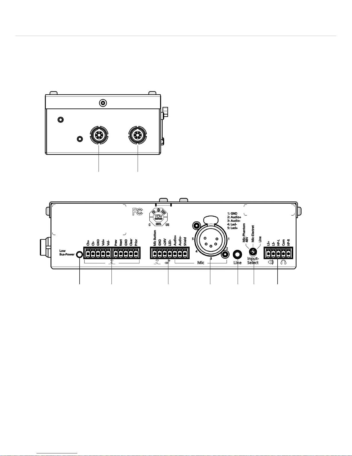
3. Connections, controls and indicators
The MCS-D 3643 provides different connections such as the 5-pin / 7-pin Phoenix connector, 5-pin XLR, mini jack
(3.5 mm) and two Lemo connectors to connect external components such as buttons, a gooseneck microphone and
loudspeaker.
Connector for conference network (Lemo)
The MCS-D 3643 is connected to the MCS-D 200 control unit or CA 4146 power supply unit via Lemo sockets.
Furthermore, the Lemo sockets are used to connect the MCS-D 3643 with one another or other microphone
units.
They are connected in a daisy chain, i.e. the first MCS-D 3643 microphone unit is connected to the MCS-D 200
control unit or to a CA 4146 power supply unit, the second system unit or microphone unit to the first one and
so on.
Low Bus Power LED
The Low Bus Power LED will illuminate red, when the power in the bus system is too low. Change the system
design (e.g. change the cabling, reduce the number of microphone units, connect another CA 4146 power
supply unit) until the Low Bus Power LED will not illuminate anymore.
Page 6

MCS-D 3643 – Connections
23
english
2 x 5-pin Phoenix connector
You can connect individual buttons to the 2 x 5-pin Phoenix connector.
Ch+ and Ch- : to adjust the language channel of a connected headphone
Vol+ and Vol- : to adjust the volume of a connected headphone
Prev : to allow the previous speaker of a request-to-speak list to speak, if the conference system is operated in
the request-to-speak mode
Next : to allow the next speaker of a request-to-speak list to speak, if the conference system is operated in the
request-to-speak mode
Clear : to turn on the chairman microphone unit while turning off the switched on or registered delegate
microphone units. Depending on the operating mode the requests to speak are cleared or not.
Prior : for prior turning on of a switched off chairman microphone unit, while muting the delegate microphone
units temporarily
GND: ground
7-pin Phoenix connector
You can connect e.g. the MPR 211 microphone or a microphone button and external indicators to the 7-pin
Phoenix connector.
Mic Button : to connect a microphone button
LED-: to connect an external LED, which displays an active microphone
+24 V : voltage source for the external LED
GND: ground
Audio + and Audio - : balanced microphone signal
Shield: shield
5-pin XLR connector
You can connect a microphone with LED ring such as Classis GM 314 E to the 5-pin XLR connector.
Mini jack (3.5 mm)
You can use the line input (mini stereo jack 3.5 mm) to connect e.g. a laptop.
Input Select Switch
To select the input source (microphone or line).
Important: Select with the switch Mic-Phantom, Mic-Electret or Line before you connect the appropriate
microphone or the laptop to the MCS-D 3643 system unit.
Mic-Phantom: 48 V Phantom power e.g. for a connected MPR 211 microphone
Mic-Electret: AB-powering e.g. for Classis GM 314 E / GM 315 E
Line: Line level e.g. for laptop
5-pin Phoenix connector
You can connect a headphone or loudspeaker to the 5-pin Phoenix connector of the MCS-D 3643 system unit.
LS + and LS -: connectors for a loudspeaker
HP-L, HP-R and Com : connectors for a headphone
Page 7

MCS-D 3643 – Installation
24
4. Installation
The MCS-D 3643 system unit provides two mounting brackets for installations under the table.
The installation of the system unit can be upright or plane.
Upright installation
For an upright installation under the table attach the mounting brackets with the supplied screws to the appropriate
holes in the housing. Refer to the picture below.
Make sure to use screws (not supplied) that are suitable for your furniture when installing the system unit under the
table.
Mounting bracket
Mounting bracket
Page 8

MCS-D 3643 – Installation
25
english
Plane installation
For a plane installation under the table attach the mounting brackets with the supplied screws to the appropriate holes
in the housing. Refer to the picture below.
Make sure to use screws (not supplied) that are suitable for your furniture when installing the system unit under the
table.
Mounting bracket
Mounting bracket
Page 9

MCS-D 3643 – Installation
26
Installation with a gooseneck microphone
• Provide appropriate holes for the button, microphone
and loudspeaker in the tabletop.
• Mount the system unit with the mounting brackets
and appropriate screws under the tabletop. Make
sure that the system unit is even with the table edge.
• Connect the button to the “Mic Button” connection
of the terminal strip.
• Connect the gooseneck microphone to the 5-pin XLR
connection.
Installation with MPR 211 microphone
• Provide an appropriate hole for the connection of the
MPR 211 in the tabletop.
• Mount the system unit with the mounting brackets
and appropriate screws under the tabletop. Make
sure that the system unit is even with the table edge.
• Connect the connecting cable of the MPR 211 to the
7-pin terminal strip.
• In this way the MPR 211 microphone becomes an
additional conference microphone unit.
• For the pin assignment please refer to the chapter
3. “Connections, controls and indicators”.
• Please observe the position of the switches at the
bottom of the MPR 211 (if necessary, please refer also
to the separate manual for the MPR 211):
– Set switch to select the basic function to “External
Logic”
– Set switch to select the operating mode to
“ON/OFF”
– Set switch to select the output level to “Low”
Page 10

MCS-D 3643 – Operation
27
english
5. Operation
Please refer also to the MCS-D 200 manual. The operating mode is set via the MCS-D 200 control unit or the iCNS
software.
The system units are connected with one another and to the MCS-D 200 control unit or CA 4146 power supply unit
in a daisy chain via a Lemo connector.
You can connect a maximum of 15 microphone units to one MCS-D 200 control unit. If the MCS-D 200 control unit
provides a second integrated power supply, you can connect a maximum of 30 microphone units. An external
CA 4146 power supply unit allows connecting a maximum of 45 microphone units.
5.1 How to operate the delegate microphone unit
Press the microphone button once to turn the microphone on or to enter a request-to-speak.
Press the microphone button once again to turn the microphone off or to delete the request-to-speak.
• When the microphone is turned on, the LED of the microphone button will illuminate.
• When a request-to-speak has been entered, the LED of the microphone button will flash. The request-to-speak is
registered and the microphone is turned on via the iCNS software.
• The number of open microphones can be limited via the MCS-D 200 control unit or the iCNS software.
• If the selected limit has been achieved, the LED of the microphone button will light up briefly. The delegate has to
try again later.
Depending on the selected operating mode, the LED of the microphone button displays the indications described
below:
Free Mode
• The microphone is turned on by pressing the microphone button, if the limit is not yet achieved. The LED of the
microphone button will illuminate.
• If the limit is exceeded, the LED of the microphone button will flash briefly. The delegate has to try later to turn on
the microphone.
Request Mode
• The request-to-speak is entered by the delegate pressing the microphone button. The LED of the microphone
button is flashing. The request-to-speak is registered and the microphone is activated via the iCNS software. The
request-to-speak can be cancelled by touching the microphone button once again.
• If the limit is exceeded, the LED of the microphone button will flash briefly. The delegate has to try again to enter
the request-to-speak later.
Auto Mode
• The delegates activate their microphone or enter a request-to-speak one after another. A delegate can activate his
microphone by pressing the microphone button if the selected limit is not yet achieved. The LED of the microphone button will illuminate.
• If the limit is exceeded, the request-to-speak is registered by the MCS-D 200 control unit and the microphone is
activated automatically as soon as another speaker turns off his microphone. The LED of the microphone button
will flash. The request-to-speak can also be cancelled by pressing the microphone button once again.
• If the selected limit for requests-to speak is exceeded, the LED of the microphone button will flash briefly. The
delegate has to try again to enter his request-to speak later.
FiFo (First In - First Out Mode)
• The delegates speak one after another. A delegate can turn on his microphone by pressing the microphone
button at any time. The LED of the microphone button will illuminate.
• If the selected limit is exceeded, the microphone of the speaker who turned on his microphone first, is deactivated
automatically (first in-first out). The LED of the microphone button of the microphone unit of the new speaker is
illuminating.
Page 11

MCS-D 3643 – Operation
28
5.2 How to operate the chairman microphone unit
The chairman can turn on his microphone unit via the microphone button at any time independent of the selected
limit. The chairman unit provides two additional buttons to conduct a meeting actively: “Prior” and “Clear”.
“Prior” button
The “Prior” button operates only, if the microphone station has been programmed as a chairman station via the
MCS-D 200.
For a brief interruption or announcement the “Prior” button must be held down. If the microphone was turned off,
it will be turned on by pressing the “Prior” button. All the other activated microphones remain muted while the LED
of the microphone button is flashing, until the “Prior” button is released.
By using the “Prior” button, chairmen of a higher level can mute the microphones of all delegate units as well as the
microphones of all chairman units of a lower level.
“Clear” button
The “Clear” button operates only, if the microphone unit has been programmed as a chairman unit via the
MCS-D 200.
• Touch the “clear” button briefly (< 1s):
The microphones of all speakers are deactivated simultaneously; requests to speak are not cleared.
• Hold down the “clear” button (> 1s):
The microphones of all speakers are deactivated simultaneously; requests to speak are cleared.
This applies for all operating modes.
5.3 How to adjust the headphone volume
Use the Vol +/- button to adjust the volume of the headphone connected to the operating panel.
The settings remain stored even when the system is turned off.
5.4 How to select the language or channel
Use the CH +/- button to select the available language channel, original channel (OR) or another information, audio
or music channel, which is then transmitted via the headphone connected.
Channels are created via the MCS-D 200 control unit or the iCNS software.
The settings remain stored even when the system is turned off.
6. Service
Servicing must be carried out by qualified service personnel only. Dismantling the system unit yourself will invalidate
the guarantee.
Page 12

MCS-D 3643 – Operation
29
english
7. Components
MCS-D 3643 System unit with connectors for microphone, loudspeaker, headphone,
microphone button, clear button, prior button, language selector and volume . . Order # 724.270
CA 1241 Piezo button without labelling . . . . . . . . . . . . . . . . . . . . . . . . . . . . . . . . . . . . . Order # 546.658
CA 1241 P Piezo button with “Prior” labelling. . . . . . . . . . . . . . . . . . . . . . . . . . . . . . . . . . Order # 546.666
CA 1241 C Piezo button with “Clear” labelling . . . . . . . . . . . . . . . . . . . . . . . . . . . . . . . . . Order # 546.674
Classis GM 314 E Gooseneck microphone with 5-pin male XLR connector, 400 mm,
LED ring, without pre-amp, incl. wind shield . . . . . . . . . . . . . . . . . . . . . . . . . . Order # 489.581
Classis GM 315 E Gooseneck microphone with 5-pin male XLR connector, 500 mm,
LED ring, without pre-amp, incl. wind shield . . . . . . . . . . . . . . . . . . . . . . . . . . Order # 489.565
MPR 211 Revoluto tabletop microphone, stone-grey Nextel
®
coating,
microphone button, controlled by microprocessor,
bare-ended connecting cable, length 3 m . . . . . . . . . . . . . . . . . . . . . . . . . . . . Order # 488.429
MPR 211 B same as above, but painted black. . . . . . . . . . . . . . . . . . . . . . . . . . . . . . . . . . . Order # 723.223
8. Supplied accessories
3 x 5-pin terminal strip (contact spacing 3.5mm)
1 x 7-pin terminal strip (contact spacing 3.5mm)
2 x Mounting brackets (incl. 4 screws)
9. Technical specifications
General
Dimensions (W x H x D). . . . . . . . . . . 181 x 49 x 96 mm
Weight . . . . . . . . . . . . . . . . . . . . . . . approx. 600 g
Temperature range . . . . . . . . . . . . . . 0 °C - +40 °C
System connections. . . . . . . . . . . . . . 2 x Push-Pull
Power supply
Power supply. . . . . . . . . . . . . . . . . . . via bus system (48 V)
Power consumption . . . . . . . . . . . . . max. 5 watt (105 mA at 48 V)
Analogue input Line In
Input level . . . . . . . . . . . . . . . . . . . . . 500 mV maximal (-6 dBV)
Input impedance . . . . . . . . . . . . . . . . 47 kΩ
Frequency response. . . . . . . . . . . . . . 20 Hz to 20 kHz (±3 dB)
Noise level. . . . . . . . . . . . . . . . . . . . . -100 dBV (A-weighted)
Microphone input Phantom Power
Supply voltage. . . . . . . . . . . . . . . . . . 48 V
Input impedance . . . . . . . . . . . . . . . . 5.5 kΩ
Level . . . . . . . . . . . . . . . . . . . . . . . . . 140 mV maximal (-17 dBV)
Frequency response. . . . . . . . . . . . . . 60 Hz to 20 kHz (±3 dB)
Noise level. . . . . . . . . . . . . . . . . . . . . -96 dBV (A-weighted)
Microphone input Electret Power
Optimised frequency response for
beyerdynamic microphone series GM31xE, GM31xQ
Supply voltage. . . . . . . . . . . . . . . . . . 4.5 V (6.81kΩ)
Noise level. . . . . . . . . . . . . . . . . . . . . -100 dBV (A-weighted)
Page 13

MCS-D 3643 – Technical Specifications
30
Loudspeaker output
Minimum impedance . . . . . . . . . . . . 8 Ω
Frequency response. . . . . . . . . . . . . . 20 Hz to 20 kHz
Headphone output
Minimum impedance . . . . . . . . . . . . 16 Ω
Frequency response. . . . . . . . . . . . . . 20 Hz to 20 kHz
Output power . . . . . . . . . . . . . . . . . . 40 mW at 16 Ω
Noise level. . . . . . . . . . . . . . . . . . . . . -86 dBV (A-weighted)
Connections
Phoenix
,
Type . . . . . . . . . . . . . . . . . . . . . . . . . Phoenix terminal strip
Number of pins . . . . . . . . . . . . . . . . . 5-pin
Contact spacing . . . . . . . . . . . . . . . . 3.5 mm
Suitable connector . . . . . . . . . . . . . . e.g. Phoenix MC 1,5/ 5-ST-3,5 (included in the delivery)
Maximum cable cross-section . . . . . . 1.5mm²
Phoenix
Type . . . . . . . . . . . . . . . . . . . . . . . . . Phoenix terminal strip
Number of pins . . . . . . . . . . . . . . . . . 7-pin
Contact spacing . . . . . . . . . . . . . . . . 3.5 mm
Suitable connector . . . . . . . . . . . . . . e.g. Phoenix MC 1,5/ 5-ST-3,5 (included in the delivery)
Maximum cable cross-section . . . . . . 1.5mm²
XLR socket
Type . . . . . . . . . . . . . . . . . . . . . . . . . Female
Number of pins . . . . . . . . . . . . . . . . . 5-pin
Jack socket
Type . . . . . . . . . . . . . . . . . . . . . . . . . Mini (3.5mm)
Version . . . . . . . . . . . . . . . . . . . . . . . Stereo
Page 14

MCS-D 3643 – Technical Specifications
31
english
5-pin Phoenix terminal strip
2x5-pin Phoenix terminal strip 7-pin Phoenix terminal strip
5-pin XLR socket
Mini jack socket (3.5 mm)
Page 15

MCS-D 3643 – Technical Specifications
32
Dimensions
How to connect MCS-D 3643 and MPR 211
Page 16

MCS-D 3643 – Installation Examples
33
english
10. Installation examples
Installation with external components and MCS-D 200 control unit
Installation with external components, MCS-D 200 control unit and external CA 4146 power supply unit
CA 43xx cable
max. 15 microphone
units
button
Classis GM 314 E
DT 1 S
button
Classis GM 314 E
DT 1 S
button
Classis GM 314 E
DT 1 S
MCS-D 3643
MCS-D 200
CA 43xx cable
max. 30 microphone
units (with second
internal power supply
in MCS-D 200)
+ CA 4100 internal power supply
button
Classis GM 314 E
DT 1 S
button
Classis GM 314 E
DT 1 S
button
Classis GM 314 E
DT 1 S
MCS-D 3643
CA 43xx cable
max. 45 microphone
units; redundant cabling
recommended for more
than 40 microphone
units
CA 4146 external power supply unit
CA 4146 external power supply unit
MCS-D 200 control unit
Page 17

DEF 1/BA MCS-D 3643 (06.12)/633.682/Hoh. • Abbildungen nicht vertragsbindend. Änderungen und Irrtümer vorbehalten • Non-contractual illustrations. Subject to change without notice. •
Illustrations non contractuelles.
Sous réserve de modifications.
beyerdynamic GmbH & Co. KG
Theresienstr. 8 | 74072 Heilbronn – Germany
Tel. +49 (0) 7131 / 617 - 0 | Fax +49 (0) 7131 / 617 - 204
info@beyerdynamic.de | www.beyerdynamic.com
Weitere Vertriebspartner weltweit finden Sie unter www.beyerdynamic.com
For further distributors worldwide, please go to www.beyerdynamic.com
 Loading...