

Page 1

MCS-D 200
OPERATING INSTRUCTIONS
Digital multimedia-based Conference System
Page 2

E
02
Note
This manual is for electro-technically qualified staff. The knowledge and the precise realisation of these instructions are necessary
for a smooth installation and security during the operation of the described products.
Due to the danger of fire special installations of power cable may be carried out by electro-technically qualified staff only.
This manual does not include each possible case of installation, operation or maintenance. For more information please contact
your beyerdynamic dealer or beyerdynamic GmbH & Co. KG.
beyerdynamic assumes no liability for errors in this documentation and for damages resulting from using this documentation
and the products described in it.
Notes for potential reconsignments
1. In order to avoid damages, please dispatch the microphone units in a strong packaging, if you need to return them.
2. If you want to return individual microphone units, please make sure that no heavy weights can damage them or the
goosenecks through the packaging.
Page 3

Contents
E
03
Table of Contents
1. Important Safety Instructions . . . . . . . . . . . . . . . . . . . . . . . . . . . . . . . . . . . . . . . . . . . . . . . . . . . . . . . . . . . . . Page 7
2. Set-up . . . . . . . . . . . . . . . . . . . . . . . . . . . . . . . . . . . . . . . . . . . . . . . . . . . . . . . . . . . . . . . . . . . . . . . . . . . . . . . . Page 8
3. MCS-D 200 Control Unit . . . . . . . . . . . . . . . . . . . . . . . . . . . . . . . . . . . . . . . . . . . . . . . . . . . . . . . . . . . . . . . . . Page 8
3.1 Controls and indicators. . . . . . . . . . . . . . . . . . . . . . . . . . . . . . . . . . . . . . . . . . . . . . . . . . . . . . . . . . . . Page 8
3.2 Putting into operation . . . . . . . . . . . . . . . . . . . . . . . . . . . . . . . . . . . . . . . . . . . . . . . . . . . . . . . . . . . . Page 9
3.2.1 Audio connection . . . . . . . . . . . . . . . . . . . . . . . . . . . . . . . . . . . . . . . . . . . . . . . . . . . . . . . . . . . . . . . . Page 9
3.2.2 Mains connection . . . . . . . . . . . . . . . . . . . . . . . . . . . . . . . . . . . . . . . . . . . . . . . . . . . . . . . . . . . . . . . . Page 10
3.2.3 How to switch the control unit on/off. . . . . . . . . . . . . . . . . . . . . . . . . . . . . . . . . . . . . . . . . . . . . . . . Page 10
3.2.4 How to connect a PC or media control system . . . . . . . . . . . . . . . . . . . . . . . . . . . . . . . . . . . . . . . . . Page 11
3.2.5 Rack mounting . . . . . . . . . . . . . . . . . . . . . . . . . . . . . . . . . . . . . . . . . . . . . . . . . . . . . . . . . . . . . . . . . . Page 11
3.2.6 How to supply the system. . . . . . . . . . . . . . . . . . . . . . . . . . . . . . . . . . . . . . . . . . . . . . . . . . . . . . . . . . Page 11
3.3 How to operate the menu of the MCS-D 200 control unit . . . . . . . . . . . . . . . . . . . . . . . . . . . . . . . Page 12
3.3.1 Menu overview of the MCS-D 200 control unit . . . . . . . . . . . . . . . . . . . . . . . . . . . . . . . . . . . . . . . . Page 12
3.3.2 Main Menu . . . . . . . . . . . . . . . . . . . . . . . . . . . . . . . . . . . . . . . . . . . . . . . . . . . . . . . . . . . . . . . . . . . . . Page 13
3.3.3 System Set-up Menus . . . . . . . . . . . . . . . . . . . . . . . . . . . . . . . . . . . . . . . . . . . . . . . . . . . . . . . . . . . . . Page 14
3.3.4 Session Menus . . . . . . . . . . . . . . . . . . . . . . . . . . . . . . . . . . . . . . . . . . . . . . . . . . . . . . . . . . . . . . . . . . . Page 16
3.3.4.1 Modes / Limit Menus . . . . . . . . . . . . . . . . . . . . . . . . . . . . . . . . . . . . . . . . . . . . . . . . . . . . . . . . . . . . . . Page 17
3.3.4.2 Channel List . . . . . . . . . . . . . . . . . . . . . . . . . . . . . . . . . . . . . . . . . . . . . . . . . . . . . . . . . . . . . . . . . . . . . Page 20
3.3.4.3 President(s). . . . . . . . . . . . . . . . . . . . . . . . . . . . . . . . . . . . . . . . . . . . . . . . . . . . . . . . . . . . . . . . . . . . . . Page 22
3.3.4.4 Interpreter . . . . . . . . . . . . . . . . . . . . . . . . . . . . . . . . . . . . . . . . . . . . . . . . . . . . . . . . . . . . . . . . . . . . . . Page 24
3.3.5 Define Channels . . . . . . . . . . . . . . . . . . . . . . . . . . . . . . . . . . . . . . . . . . . . . . . . . . . . . . . . . . . . . . . . . Page 26
3.3.6 Options. . . . . . . . . . . . . . . . . . . . . . . . . . . . . . . . . . . . . . . . . . . . . . . . . . . . . . . . . . . . . . . . . . . . . . . . . Page 28
3.3.6.1 Time . . . . . . . . . . . . . . . . . . . . . . . . . . . . . . . . . . . . . . . . . . . . . . . . . . . . . . . . . . . . . . . . . . . . . . . . . . . Page 28
3.3.6.2 Ports . . . . . . . . . . . . . . . . . . . . . . . . . . . . . . . . . . . . . . . . . . . . . . . . . . . . . . . . . . . . . . . . . . . . . . . . . . . Page 29
3.3.6.3 MCS-D Info. . . . . . . . . . . . . . . . . . . . . . . . . . . . . . . . . . . . . . . . . . . . . . . . . . . . . . . . . . . . . . . . . . . . . . Page 29
3.3.7 Delegate IDs. . . . . . . . . . . . . . . . . . . . . . . . . . . . . . . . . . . . . . . . . . . . . . . . . . . . . . . . . . . . . . . . . . . . . Page 30
3.3.7.1 ID List . . . . . . . . . . . . . . . . . . . . . . . . . . . . . . . . . . . . . . . . . . . . . . . . . . . . . . . . . . . . . . . . . . . . . . . . . . Page 31
3.3.7.2 Set IDs. . . . . . . . . . . . . . . . . . . . . . . . . . . . . . . . . . . . . . . . . . . . . . . . . . . . . . . . . . . . . . . . . . . . . . . . . . Page 32
3.3.7.3 Conflicts . . . . . . . . . . . . . . . . . . . . . . . . . . . . . . . . . . . . . . . . . . . . . . . . . . . . . . . . . . . . . . . . . . . . . . . . Page 32
3.3.8 Interpreter IDs . . . . . . . . . . . . . . . . . . . . . . . . . . . . . . . . . . . . . . . . . . . . . . . . . . . . . . . . . . . . . . . . . . . Page 33
3.3.8.1 Interpreter ID List . . . . . . . . . . . . . . . . . . . . . . . . . . . . . . . . . . . . . . . . . . . . . . . . . . . . . . . . . . . . . . . . Page 34
3.3.8.2 Set Interpreter IDs . . . . . . . . . . . . . . . . . . . . . . . . . . . . . . . . . . . . . . . . . . . . . . . . . . . . . . . . . . . . . . . . Page 34
3.3.8.3 Conflicts . . . . . . . . . . . . . . . . . . . . . . . . . . . . . . . . . . . . . . . . . . . . . . . . . . . . . . . . . . . . . . . . . . . . . . . . Page 35
3.3.9 Technician IDs . . . . . . . . . . . . . . . . . . . . . . . . . . . . . . . . . . . . . . . . . . . . . . . . . . . . . . . . . . . . . . . . . . . Page 35
3.3.10 DAI/DDI Management. . . . . . . . . . . . . . . . . . . . . . . . . . . . . . . . . . . . . . . . . . . . . . . . . . . . . . . . . . . . . Page 36
3.3.10.1Ext. DAI ID List . . . . . . . . . . . . . . . . . . . . . . . . . . . . . . . . . . . . . . . . . . . . . . . . . . . . . . . . . . . . . . . . . . . Page 37
3.3.10.2DAI Set-up . . . . . . . . . . . . . . . . . . . . . . . . . . . . . . . . . . . . . . . . . . . . . . . . . . . . . . . . . . . . . . . . . . . . . . Page 37
3.3.10.3DAI Control . . . . . . . . . . . . . . . . . . . . . . . . . . . . . . . . . . . . . . . . . . . . . . . . . . . . . . . . . . . . . . . . . . . . . Page 39
4. CA 4115/30/45 Power Supply Unit . . . . . . . . . . . . . . . . . . . . . . . . . . . . . . . . . . . . . . . . . . . . . . . . . . . . . . . . . Page 41
4.1 Controls and indicators. . . . . . . . . . . . . . . . . . . . . . . . . . . . . . . . . . . . . . . . . . . . . . . . . . . . . . . . . . . . Page 41
4.2 Connection. . . . . . . . . . . . . . . . . . . . . . . . . . . . . . . . . . . . . . . . . . . . . . . . . . . . . . . . . . . . . . . . . . . . . . Page 42
4.2.1 Control unit - power supply unit . . . . . . . . . . . . . . . . . . . . . . . . . . . . . . . . . . . . . . . . . . . . . . . . . . . . Page 42
4.2.2 Microphone stations - power supply unit . . . . . . . . . . . . . . . . . . . . . . . . . . . . . . . . . . . . . . . . . . . . . Page 42
4.3 How to switch on the power supply unit . . . . . . . . . . . . . . . . . . . . . . . . . . . . . . . . . . . . . . . . . . . . . Page 42
5. CA 4522/44/66 Digital / Analogue Interface (DAI) . . . . . . . . . . . . . . . . . . . . . . . . . . . . . . . . . . . . . . . . . . . . . Page 43
5.1 Controls and Indicators. . . . . . . . . . . . . . . . . . . . . . . . . . . . . . . . . . . . . . . . . . . . . . . . . . . . . . . . . . . . Page 44
6. CA 4577 Digital / Digital Interface (DDI) . . . . . . . . . . . . . . . . . . . . . . . . . . . . . . . . . . . . . . . . . . . . . . . . . . . . Page 45
6.1 Controls and indicators. . . . . . . . . . . . . . . . . . . . . . . . . . . . . . . . . . . . . . . . . . . . . . . . . . . . . . . . . . . . Page 45
7. Microphone Stations . . . . . . . . . . . . . . . . . . . . . . . . . . . . . . . . . . . . . . . . . . . . . . . . . . . . . . . . . . . . . . . . . . . . Page 46
7.1 MCS-D 2073 . . . . . . . . . . . . . . . . . . . . . . . . . . . . . . . . . . . . . . . . . . . . . . . . . . . . . . . . . . . . . . . . . . . . . Page 46
7.1.1 Controls and indicators . . . . . . . . . . . . . . . . . . . . . . . . . . . . . . . . . . . . . . . . . . . . . . . . . . . . . . . . . . . . Page 46
7.1.2 How to turn the microphone on . . . . . . . . . . . . . . . . . . . . . . . . . . . . . . . . . . . . . . . . . . . . . . . . . . . . Page 48
7.1.3 How to set the volume of the headphone . . . . . . . . . . . . . . . . . . . . . . . . . . . . . . . . . . . . . . . . . . . . Page 49
7.1.4 How to set the language or channel. . . . . . . . . . . . . . . . . . . . . . . . . . . . . . . . . . . . . . . . . . . . . . . . . Page 49
7.1.5 Menu buttons . . . . . . . . . . . . . . . . . . . . . . . . . . . . . . . . . . . . . . . . . . . . . . . . . . . . . . . . . . . . . . . . . . . Page 49
7.1.6 Menu settings . . . . . . . . . . . . . . . . . . . . . . . . . . . . . . . . . . . . . . . . . . . . . . . . . . . . . . . . . . . . . . . . . . . Page 50
7.1.7 How to switch on a microphone while phoning . . . . . . . . . . . . . . . . . . . . . . . . . . . . . . . . . . . . . . . Page 52
7.1.8 How to operate the navigator buttons . . . . . . . . . . . . . . . . . . . . . . . . . . . . . . . . . . . . . . . . . . . . . . . Page 52
7.1.9 Display . . . . . . . . . . . . . . . . . . . . . . . . . . . . . . . . . . . . . . . . . . . . . . . . . . . . . . . . . . . . . . . . . . . . . . . . . Page 52
7.1.10 MCS-D 2073 as chairman station . . . . . . . . . . . . . . . . . . . . . . . . . . . . . . . . . . . . . . . . . . . . . . . . . . . . Page 53
7.2 MCS-D 3121 / 3123 . . . . . . . . . . . . . . . . . . . . . . . . . . . . . . . . . . . . . . . . . . . . . . . . . . . . . . . . . . . . . . . Page 54
7.2.1 Controls and indicators . . . . . . . . . . . . . . . . . . . . . . . . . . . . . . . . . . . . . . . . . . . . . . . . . . . . . . . . . . . . Page 54
7.2.2 How to turn on the MCS-D 3121 . . . . . . . . . . . . . . . . . . . . . . . . . . . . . . . . . . . . . . . . . . . . . . . . . . . . Page 56
7.2.3 How to operate the MCS-D 3123 chairman station . . . . . . . . . . . . . . . . . . . . . . . . . . . . . . . . . . . . . Page 57
Page 4

E
04
Page 5

Contents
E
05
7.3 MCS-D 3171 / 3173 . . . . . . . . . . . . . . . . . . . . . . . . . . . . . . . . . . . . . . . . . . . . . . . . . . . . . . . . . . . . . . . Page 58
7.3.1 Controls and indicators . . . . . . . . . . . . . . . . . . . . . . . . . . . . . . . . . . . . . . . . . . . . . . . . . . . . . . . . . . . . Page 58
7.3.2 How to display the Device ID . . . . . . . . . . . . . . . . . . . . . . . . . . . . . . . . . . . . . . . . . . . . . . . . . . . . . . . Page 59
7.3.3 How to display messages . . . . . . . . . . . . . . . . . . . . . . . . . . . . . . . . . . . . . . . . . . . . . . . . . . . . . . . . . . Page 60
7.3.4 How to turn on the MCS-D 3171 . . . . . . . . . . . . . . . . . . . . . . . . . . . . . . . . . . . . . . . . . . . . . . . . . . . . Page 60
7.3.5 How to adjust the headphone volume . . . . . . . . . . . . . . . . . . . . . . . . . . . . . . . . . . . . . . . . . . . . . . . Page 61
7.3.6 How to select the language or channel . . . . . . . . . . . . . . . . . . . . . . . . . . . . . . . . . . . . . . . . . . . . . . Page 61
7.3.7 How to operate the MCS-D 3173 chairman station . . . . . . . . . . . . . . . . . . . . . . . . . . . . . . . . . . . . . Page 61
7.4 MCS-D 202 . . . . . . . . . . . . . . . . . . . . . . . . . . . . . . . . . . . . . . . . . . . . . . . . . . . . . . . . . . . . . . . . . . . . . . Page 62
7.4.1 Controls and indicators . . . . . . . . . . . . . . . . . . . . . . . . . . . . . . . . . . . . . . . . . . . . . . . . . . . . . . . . . . . . Page 62
7.4.2 How to program the relay channel buttons 1-3 . . . . . . . . . . . . . . . . . . . . . . . . . . . . . . . . . . . . . . . . Page 64
7.4.3 Output channels A and B . . . . . . . . . . . . . . . . . . . . . . . . . . . . . . . . . . . . . . . . . . . . . . . . . . . . . . . . . . Page 65
7.4.3.1 How to program the output channels A and B . . . . . . . . . . . . . . . . . . . . . . . . . . . . . . . . . . . . . . . . Page 65
7.4.4 Call buttons . . . . . . . . . . . . . . . . . . . . . . . . . . . . . . . . . . . . . . . . . . . . . . . . . . . . . . . . . . . . . . . . . . . . . Page 66
7.4.5 How to assign the interpreter ID . . . . . . . . . . . . . . . . . . . . . . . . . . . . . . . . . . . . . . . . . . . . . . . . . . . . Page 68
7.4.6 How to save settings on a chip card . . . . . . . . . . . . . . . . . . . . . . . . . . . . . . . . . . . . . . . . . . . . . . . . . Page 70
7.4.7 How to read the chip card data. . . . . . . . . . . . . . . . . . . . . . . . . . . . . . . . . . . . . . . . . . . . . . . . . . . . . Page 70
8. Examples . . . . . . . . . . . . . . . . . . . . . . . . . . . . . . . . . . . . . . . . . . . . . . . . . . . . . . . . . . . . . . . . . . . . . . . . . . . . . . Page 72
9. Components . . . . . . . . . . . . . . . . . . . . . . . . . . . . . . . . . . . . . . . . . . . . . . . . . . . . . . . . . . . . . . . . . . . . . . . . . . . Page 84
10. Optional Accessories . . . . . . . . . . . . . . . . . . . . . . . . . . . . . . . . . . . . . . . . . . . . . . . . . . . . . . . . . . . . . . . . . . . . Page 84
11. List of Language Codes . . . . . . . . . . . . . . . . . . . . . . . . . . . . . . . . . . . . . . . . . . . . . . . . . . . . . . . . . . . . . . . . . . Page 85
12. Technical Specifications . . . . . . . . . . . . . . . . . . . . . . . . . . . . . . . . . . . . . . . . . . . . . . . . . . . . . . . . . . . . . . . . . . Page 87
Page 6

Introduction
E
06
Thank you for selecting the digital multimedia-based MCS-D 200 conference system from beyerdynamic. Please take some time
to read carefully through this manual before setting up the equipment.
This manual describes the installation and operation of the MCS-D 200 system without the control and configuration via PC.
MCS-D 200 is a fully digital multimedia-based conference system in single-cable design. It can be used for small and large
events in permanent installations or for mobile use.
The system includes the following components:
• MCS-D 200 Control Unit
• MCS-D 2073 Delegate / Chairman Station
• MCS-D 202 Interpreter Stations
• MCS-D 3121 Delegate Station and MCS-D 3123 Chairman Station
• MCS-D 3171 Delegate Station and MCS-D 3173 Chairman Station
• Cabling via “NetRateBus”
The NetRateBus is a special kind of cabling which allows operating all services such as microphone channels, interpreting
channels, control, network, telephone and safety precautions simultaneously on 54 channels without any interferences.
The NetRateBus allows different types of cabling such as in a daisy chain, star or tree structure with any branch. The setup is
clear and simple.
One conference system can consist of a maximum of 1,400 microphone units.
For the digital interpreter stations there is no additional control unit needed.
Third party devices such as PCs, automatic cameras with pan, tilt, zoom, recording devices, output devices or display screen in
the hall can be connected.
With the MultiSession Management several meetings can be controlled simultanously with one control unit and the software.
The individual conference rooms can be combined to one large group or conference room by changing the software settings
accordingly.
Page 7

Safety Instructions
E
77
1. Important Safety Instructions
Control Unit and Power Supply Units
• READ these instructions.
• KEEP these instructions.
• HEED all warnings.
• Follow all instructions.
• Do not use this apparatus near water.
• Clean only with a dry cloth.
• Do not block any ventilation openings. Install in accordance with the manufacturer’s instructions.
• Do not install near any heat sources such as radiators, heat registers, stoves or other apparatus (including amplifiers) that
produce heat.
• Do not defeat the safety purpose of the polarised or grounding-type plug. A polarised plug has two blades with one wider
than the other. A grounding type plug has two blades and a third grounding prong. The wide blade or the third prong are
provided for your safety. If the provided plug does not fit into your outlet, consult an electrician for replacement of the
obsolete outlet.
• Protect the power cord from being walked on or pinched particularly at plugs, convenience receptacles, and the point where
they exit from the apparatus.
• Only use attachements/accessories specified by the manufacturer.
• Use only with the cart, stand, tripod, bracket or table specified by the manufacturer or sold with the apparatus. When a cart
is used, use caution when moving the cart/apparatus combination to avoid injury from tip-over.
• Unplug this apparatus during lightning storms or when unused for long periods of time.
• Refer all servicing to qualified service personnel. Servicing is required when the apparatus has been damaged in any way,
such as power-supply cord or plug is damaged, liquid has been spilled or objects have fallen into the apparatus, the
apparatus has been exposed to rain or moisture, does not operate normally, or has been dropped.
• The equipment must be set up so that the mains switch, mains plug and all connection on the rear of the device are easily
accessible.
• The equipment must be connected to a mains socket that has an earth contact.
• Never expose the equipment to rain or a high level of humidity. For this reason do not install it in the immediate vicinity of
swimming pools, showers, damp basement rooms or other areas with unusually high atmospheric humidity.
• Do not use the device/s outside. To reduce the risk of fire or electric shock, do not expose this/these device/s to rain or
moisture.
• Never place objects containing liquid (e.g. vases or drinking glasses) on the equipment. Liquids in the equipment could cause
a short circuit.
• Lay all connection cables so that they do not present a trip hazard.
• Check whether the connection figures comply with the existing mains supply. Serious damage could occur due to connecting
the system to the wrong power supply. An incorrect mains voltage could damage the equipment or cause an electric shock.
• This equipment needs adequate ventilation. Do not cover ventilation grilles. If the heat it generates cannot be dissipated,
the equipment could be damaged or flammable materials in its immediate vicinity could be ignited. Take care to ensure that
the air can circulate freely through the ventilation grilles and keep flammable materials away.
• Never place naked flames near the equipment.
• If the equipment causes a blown fuse or a short circuit, disconnect it from the mains and have it checked and repaired.
• Do not open the equipment without authorisation. You could receive an electric shock. Leave all service work to authorised
expert personnel.
• Do not hold the mains cable with wet hands. There must be no water or dust on the contact pins. In both cases you could
receive an electric shock.
• The mains cable must be firmly connected. If it is loose there is a fire hazard.
• Always pull out the mains cable from the mains and/or from the equipment by the plug - never by the cable. The cable could
be damaged and cause an electric shock or fire.
• If the power cable is connected, avoid contact of the unit with other metallic objects.
• Do not insert objects into the ventilation grilles or other openings. You could damage the equipment and/or injure yourself.
• Do not use the equipment if the mains plug is damaged.
• When installing the device into a 19" rack, make sure that the mains switch, mains plug and all connection on the rear of
the device are easily accessible.
Microphone Units
• Conference microphone stations with metal casings are heavy, so always position them on a secure surface.
• If the microphone stations have a gooseneck microphone take care that you do not injure yourself on this e.g. poke it into
your eye
• To align the gooseneck microphone on the microphone station and to avoid twisting it too far and causing
premature wear, always grip the microphone by the bottom flexible section never by the microphone head or
by the rigid tube. The gooseneck must be bent no further than an angle of 90 ° maximum.
Page 8
MCS-D 200 Control Unit
E
08
3. MCS-D 200 Control Unit
The MCS-D 200 control unit is the heart of the system. It controls the delegate, chairman and interpreter microphone stations.
The MCS-D 200 control unit has a modular power supply unit to power a maximum of 15 microphone stations (optional 30). If
more than 30 microphone stations are to be used, additional power supply units are necessary to meet the power requirement.
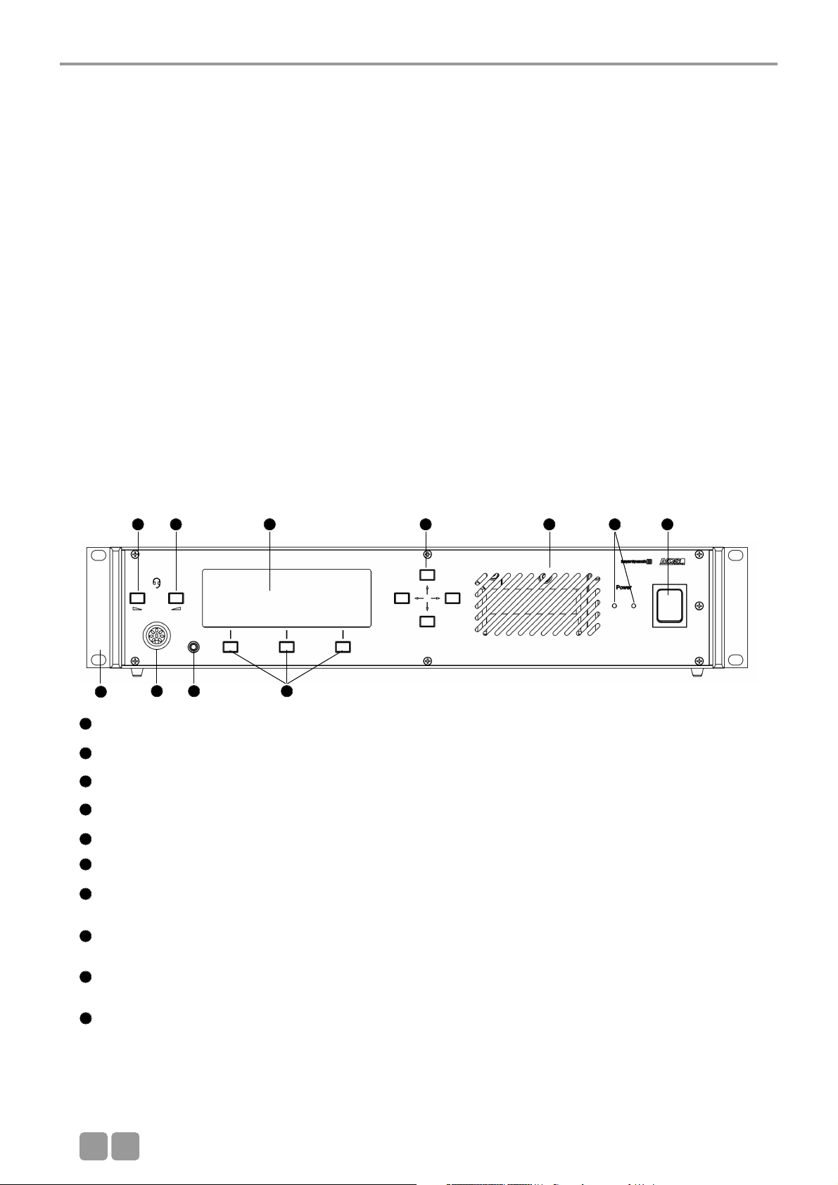
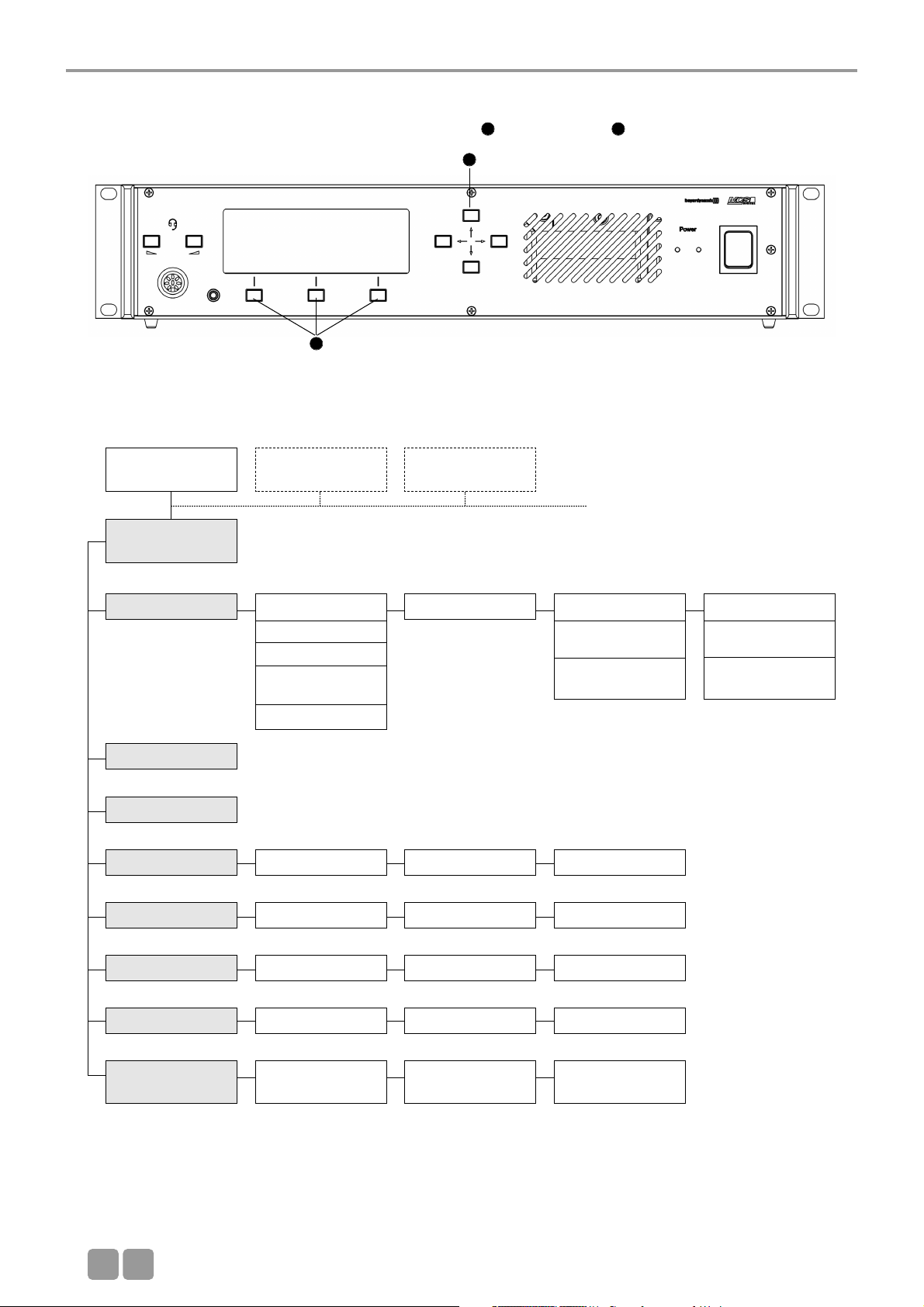
3.1 Controls and indicators
Front view
Power switch
Power on LEDs (the number of illuminated LEDs indicates the number of power supply units integrated into the control unit)
Ventilation grille. Do not cover to avoid overheating.
Socket to connect microphone or headset (8 pin DIN 45326) - inactive
Headphone socket (3.5 mm) - inactive
Volume buttons (left, right) - inactive
Display with 20 characters / 4 lines. Three lines are used for various menu data. The bottom line is used for the description
of the Control Keys.
Navigator buttons (left, right, up, down). Using the navigator bottoms up / down you can scroll through the menu; using
the navigator bottoms left / right you can enter data.
Menu buttons; so-called “hot keys”. Depending on the menu, they act as ENTER, EXIT, VOL-, SETUP, VOL +, SET, LIMIT,
MODE button. The description is displayed in the lower line.
Mounting brackets for 19" rack mounting.
1
2
3
4
5
6
7
8
9
2. Set-up
The MCS-D 200 system may only be installed by staff acquainted with the appropriate safety instructions.
The MCS-D 200 control unit and the power supply units have been developed for installation on tables or 19"-mounting.
Do not cover the ventilating grille. When setting up the system please follow the safety instructions mentioned in chapter 1.
Furthermore, please note
• the ambient temperature of the installation site must not exceed 50 °C.
• there must not be exceeding dust and humidity at the installation site.
• that the unit is not exposed to direct sunlight.
• the connections must be protected against direct access during operation.
• that there must be a strain relief of the cables.
• the installation site must be protected against vibrations.
10
6 6 7 8 3 12
954
10
Page 9
MCS-D 200 Control Units
E
09
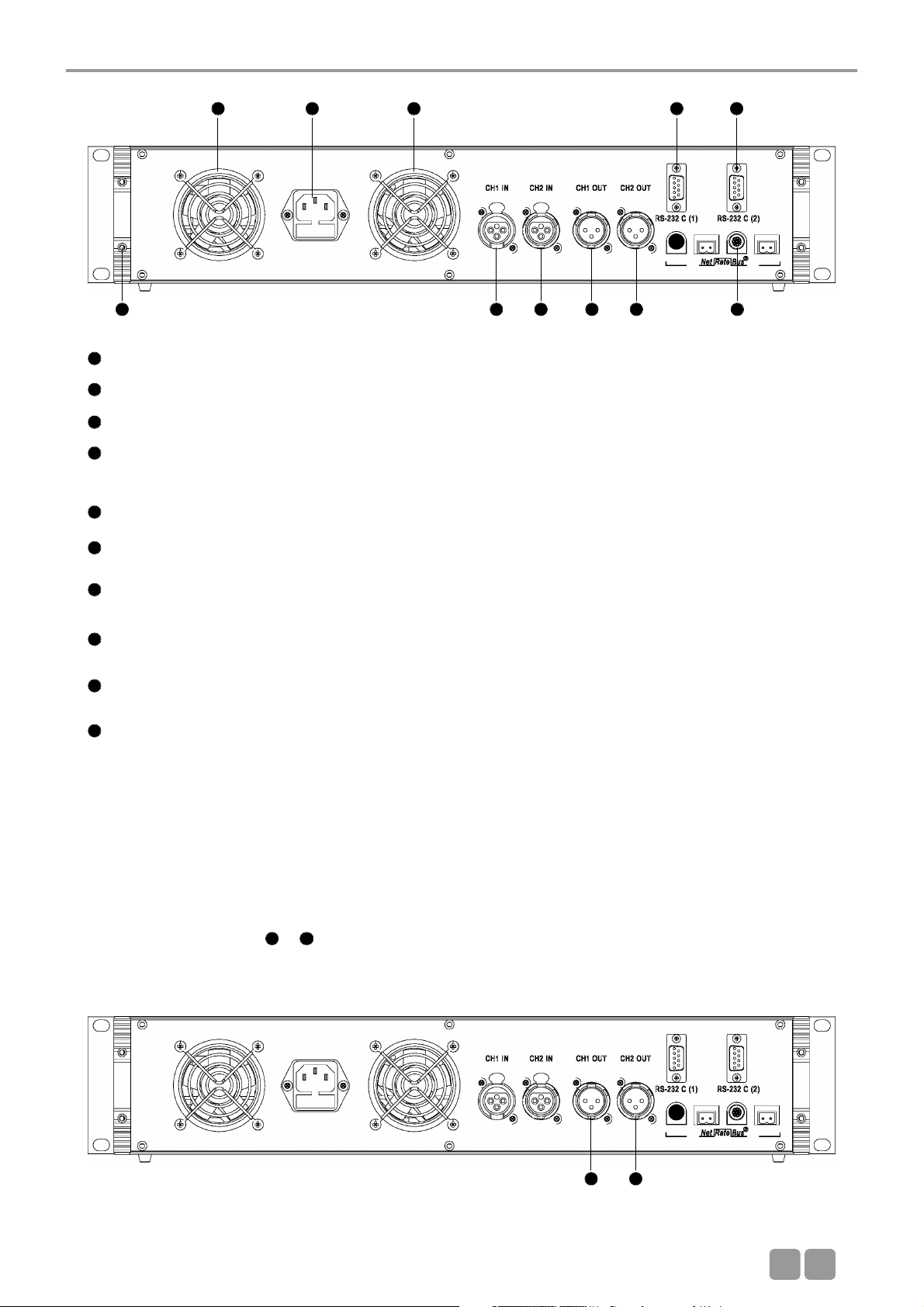
Mains connection with fuse (6.3 A short-circuit protection)
NetRateBus conference sockets, MCS-D 200 with 1 Push-Pull socket to connect other power supply units for example.
Fan outlet (number of fan outlets depends on the number of power supply units integrated into the control unit)
RS 232 C (1). 9-pin Sub-D connection for PC or media control system.
Note: A PC is connected via a connecting cable (1:1) , no null modem cable.
If you use other devices, please observe the pin wiring. The configuration is done via the control unit.
RS 232 C (2). The connection corresponds to RS 232 C (1).
CH1 IN: XLR LINE IN input (female), 0 dBm, balanced. The input signal is routed to the loudspeakers of the microphone
stations or to any output. Settings are done via the control unit.
CH2 IN: XLR LINE IN input (female), 0 dBm, balanced. The input signal is routed to the loudspeakers of the microphone
units or to any output. Settings are done via the control unit.
CH1 OUT: XLR LINE OUT output (male), 0 dBm, balanced. Master output of all microphones or any channel; programmable
for recording or broadcasting applications.
CH2 OUT: XLR LINE OUT output (male), 0 dBm, balanced. Master output of all microphones or any channel; programmable
for recording or broadcasting applications..
End profile
Note:
For more inputs and outputs connect a CA 45xx D/A Interface.
11
12
13
14
15
16
17
18
19
20
Rear view
3.2 Putting into operation
13 11 13 14
121918171620
15
1918
3.2.1 Audio connection
• Connect the master output or of the MCS-D 200 control unit to the input of a mixing console or mixing amplifier.
• Always route cables running to the unit where they will not be damaged by heavy or sharp objects
18 19
Page 10
MCS-D 200 Control Unit
E
10
Caution:
• Always turn off the power when making input or output connections.
All turned on additional power supply units remain in stand-by mode even if the MCS-D 200 control unit is turned
off.
• To boot the system at least 1 device has to be connected to the control unit. Otherwise the display indicates
“Initialisation” continuously.
Rear view Front view
11
11
12
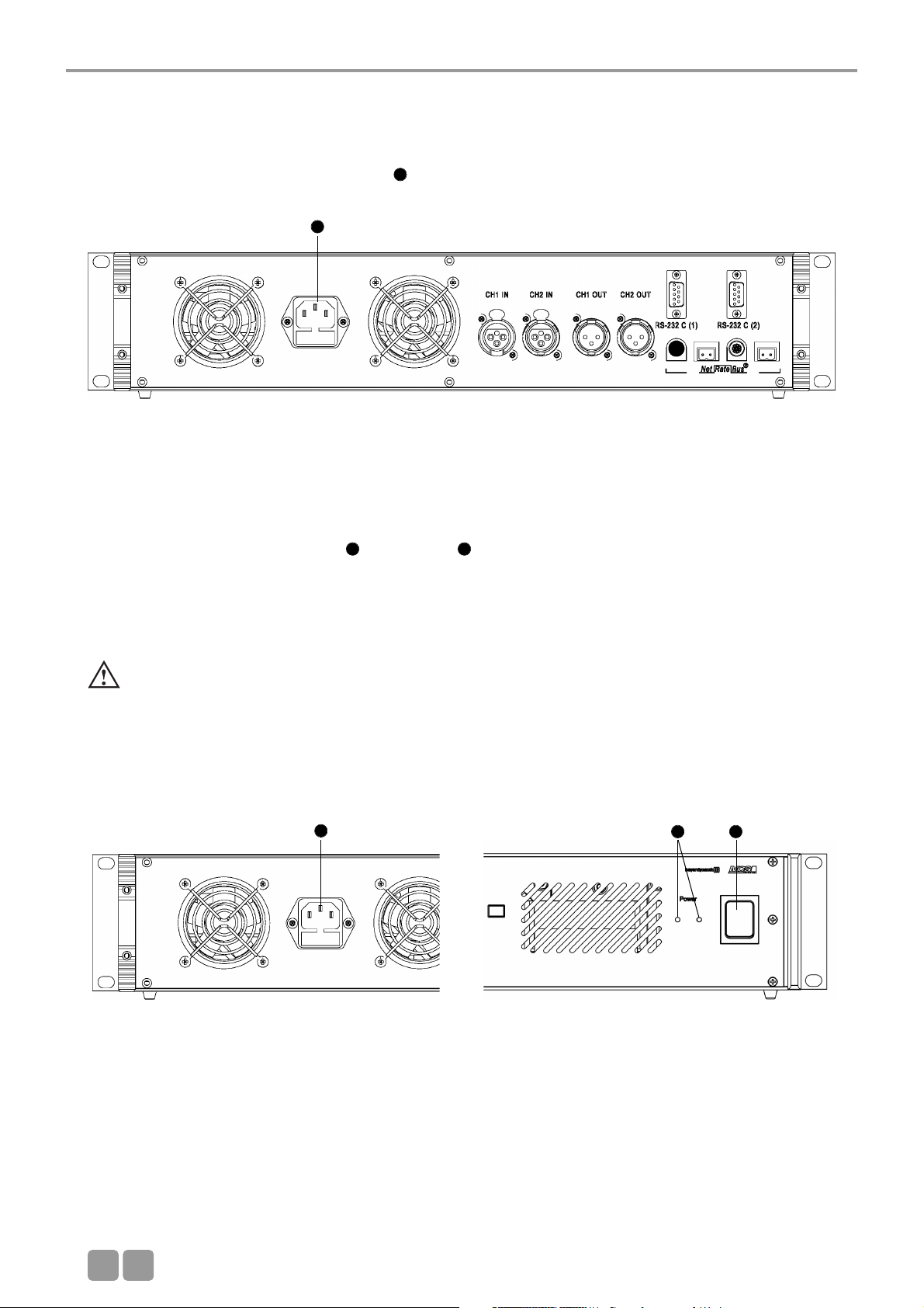
3.2.2 Mains connection
• Verify that the voltage rating of the unit matches that of the AC mains outlet you are to use. If you connect the unit to the
wrong voltage, you may seriously damage it.
• Always route cables running to the unit where they will not be damaged by heavy or sharp objects.
• Connect the MCS-D 200 control unit to the mains . The internal power supply unit of the control unit can adjust
auto matically between 100 V and 240 V at 50 - 60 Hz.
11
3.2.3 How to switch the control unit on/off
• Before switching the MCS-D 200 control unit on, please check all connections. If there are additional power supply units
connected to the control unit, we recommend switching on the devices as described in the following:
1. Switch on all additional power supply units. The illuminated power switch displays the stand-by mode.
2. Switch on the MCS-D 200 control unit . The Power LED is illuminated.
• When switching on, the system is booted up. A data communication is not yet possible. As soon as the control unit displays
the main menu and the microphone stations the default display (time or ID), the boot process is finished and the data
communication can start.
• When switching off, all settings of the MCS-D 200 control unit are stored.
1 2
Page 11
MCS-D 200 Control Unit
E
11
3.2.5 Rack mounting
• When mounting the MCS-D 200 control unit into a 19"-rack housing leave 1 U for a ventilation panel above and
under the control unit.
• Make sure that the mains switch, mains plug and all connection on the rear of the device are easily accessible.
3.2.6 How to supply the system
• All microphone stations, D/A interfaces and adapters are powered via the system. They do not have their own power supply.
• The number of the required power supply units depends on the number of microphone stations and the system set-up
including different cable lengths and operating mode.
• The following list shows how many devices such as microphone stations, interfaces and adapters can be powered by the
system.
MCS-D 200 control unit with 1 power pack (= 2 A) for approx. 15 microphone stations
MCS-D 200 control unit with 2 power packs (= 4 A) for approx. 30 microphone stations
When the system is extended with additional power supply units:
Power supply unit with 1 power pack (= 2 A) for approx. 15 microphone stations
Power supply unit with 2 power packs (= 4 A) for approx. 30 microphone stations
Power supply unit with 3 power packs (= 6 A) for approx. 45 microphone stations
Note:
In this rule of thumb, an adapter (CA 4212/13/14 or CA 4222/23/24) approximately counts as half a microphone station.
Example of a system set-up:
1 MCS-D 200 control unit with 2 power packs . . . . . . . . . . . . 10 MCS-D 202 interpreter stations
+ 1 D/A interface
+ 2 adapters
+
1 Power supply unit with 2 power packs . . . . . . . . . . . . . . . . . for 30 microphone stations
+
1 Power supply unit with 3 power packs . . . . . . . . . . . . . . . . . for 45 microphone stations
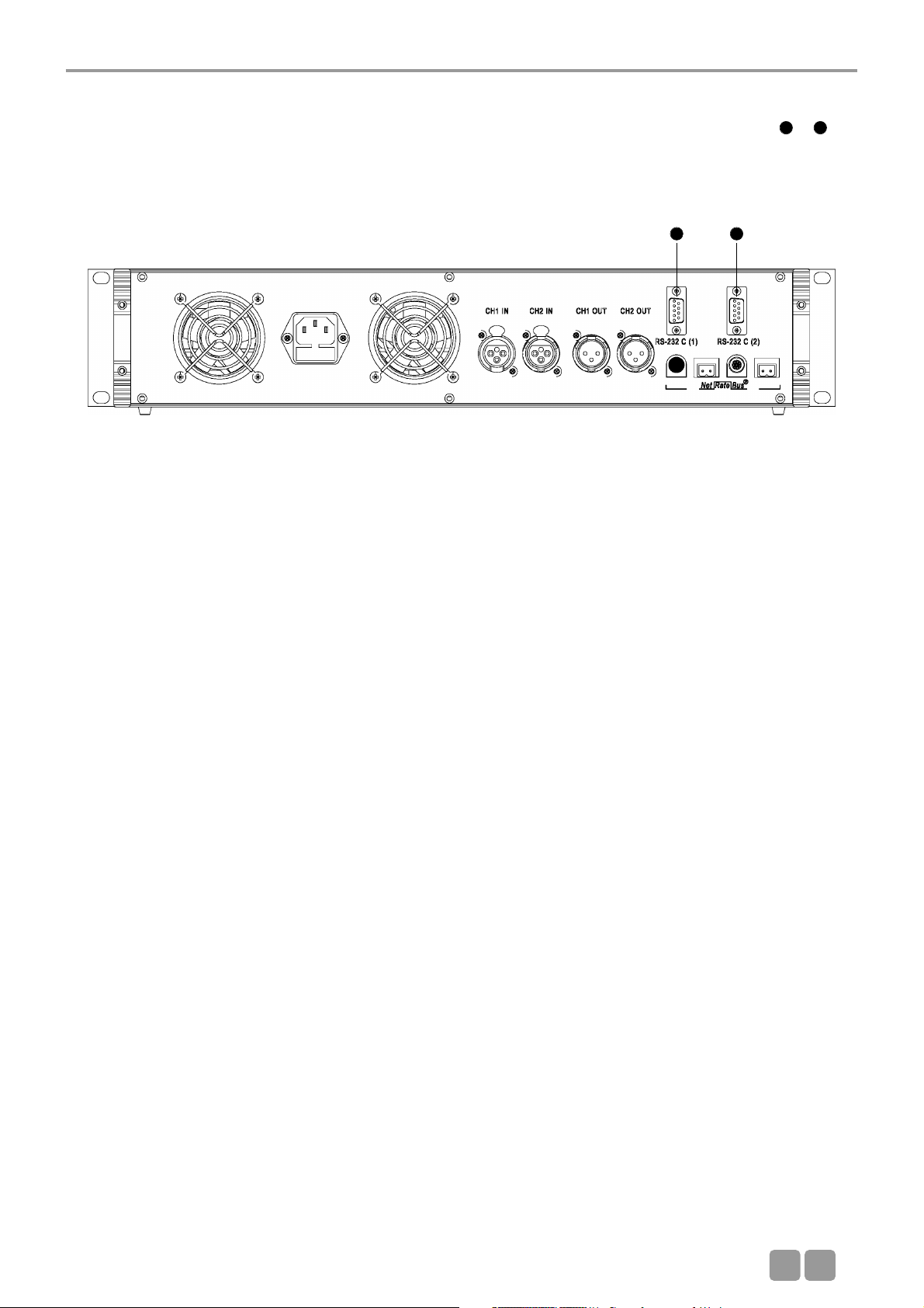
3.2.4 How to connect a PC or media control system
• If you would like to connect a PC or media control system to the MCS-D 200 control unit, use the RS 232 connection or .
• In order to connect a PC use a standard RS 232 cable, straight - no null modem cable. If you connect other devices, please
observe the pin assignment.
• The system is configured via the MCS-D 200 control unit, please refer also to chapter 3.3 “How to operate the menu of the
MCS-D 200 control unit”.
14 15
14 15
Page 12
MCS-D 200 Control Unit
E
12
3.3 How to operate the menu of the MCS-D 200 control unit
• You can scroll through the menu by using the navigator buttons and menu buttons .
3.3.1 Menu overview of the MCS-D 200 control unit
8 9
8
9
MAIN MENU
SESSION [01]
MAIN MENU*
SESSION [02]
MAIN MENU*
SESSION [03]
SYSTEM
SETUP MENUS
1. Session 1.1 Modes/Limits
1.1.1 Free
1.1.2 Request
1.1.3 Auto-Free
Auto Request
1.1.4 FiFo
1.2 Channel List 1.3 President(s)
1.3.1
Set President(s)
1.3.2
Priority Level(s)
1.4 Interpreter
1.4.1
Select Channel(s)
1.4.2
Select Booth(s)
2. Define Channels
3. Message(s)**
4. Options 4.1 Time 4.2 Ports 4.3 MCS-D Infos
5. Delegate IDs 5.1 ID List 5.2 Set IDs 5.3 Conflicts
6. Interpreter IDs 6.1 ID List 6.2 Set IDs 6.3 Conflicts
7. Technician IDs 7.1 ID List 7.2 Set IDs 7.3 Conflicts
8. DAI/DDI
Management
8.1 Ext. DAI/DDI
ID List
8.2 DAI/DDI
Setup
8.3 DAI/DDI
Control
*Only in MultiSession operation via iCNS. It is not possible to adjust settings or only to a certain extent.
**Inactive. This function is only available by using the iCNS software.
Page 13
MCS-D 200 Control Unit
E
13
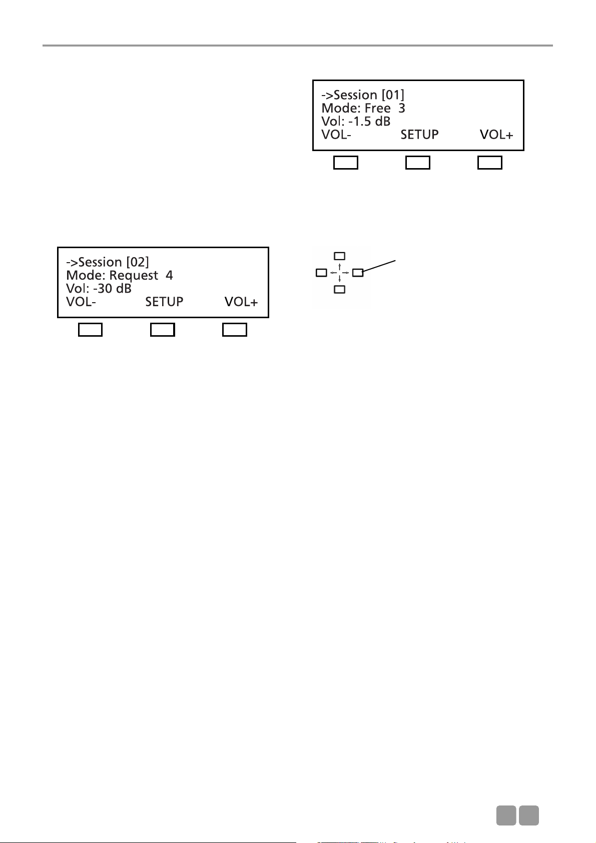
3.3.2 Main menu
The main menu displays:
the session number (here it is session 01),
the current operating mode (here it is: Free),
the number of open microphones (here the limit is: 3) and
the volume of the loudspeakers of the microphone station
(here it is -1.5 dB)
MultiSession: How to change to the next meeting
In the MultiSession operation, i.e. when the same MCS-D 200 control unit is used for several meetings, the right and left hand
navigator buttons can be used for selecting the individual meetings.
The main menu indicates the settings such as operating mode, limit and volume of the selected meeting.
The iCNS software is required for the MultiSession operation.
Conference Volume: VOL- and VOL+ buttons
To increase or reduce the volume of the selected meeting (3rd line of the main menu) directly. Press the left hand button
(VOL-) to reduce the volume; press the right hand button (VOL+) to increase the volume. The volume is changed in steps of
1.5 dB from -94.5 dB to 0 dB.
SETUP Button
Press the SETUP button to access the SYSTEM SETUP menus and SESSION menus (refer to the illustration of the menu overview
of the MCS-D 200 control unit).
Note:
The SYSTEM SETUP menus are for the general system settings = GLOBAL SYSTEM SETTINGS : Define Channels, Message(s),
Options, Delegate IDs, Interpreter IDs, Technician IDs and DAI/DDI Management. All devices, channels, messages and options of
the whole MCS-D 200 system are defined via these menus.
In the SESSION menus you can prepare settings for individual meetings.
Use the right and left hand
navigator buttons to toggle
between the individual
meetings.
Page 14
MCS-D 200 Control Unit
E
14
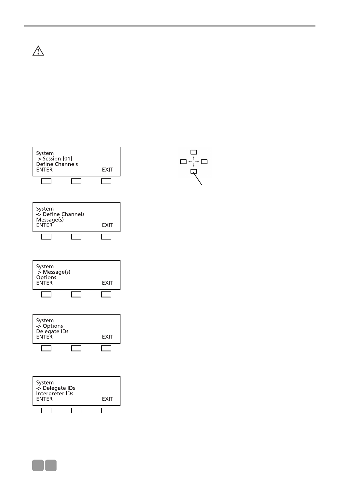
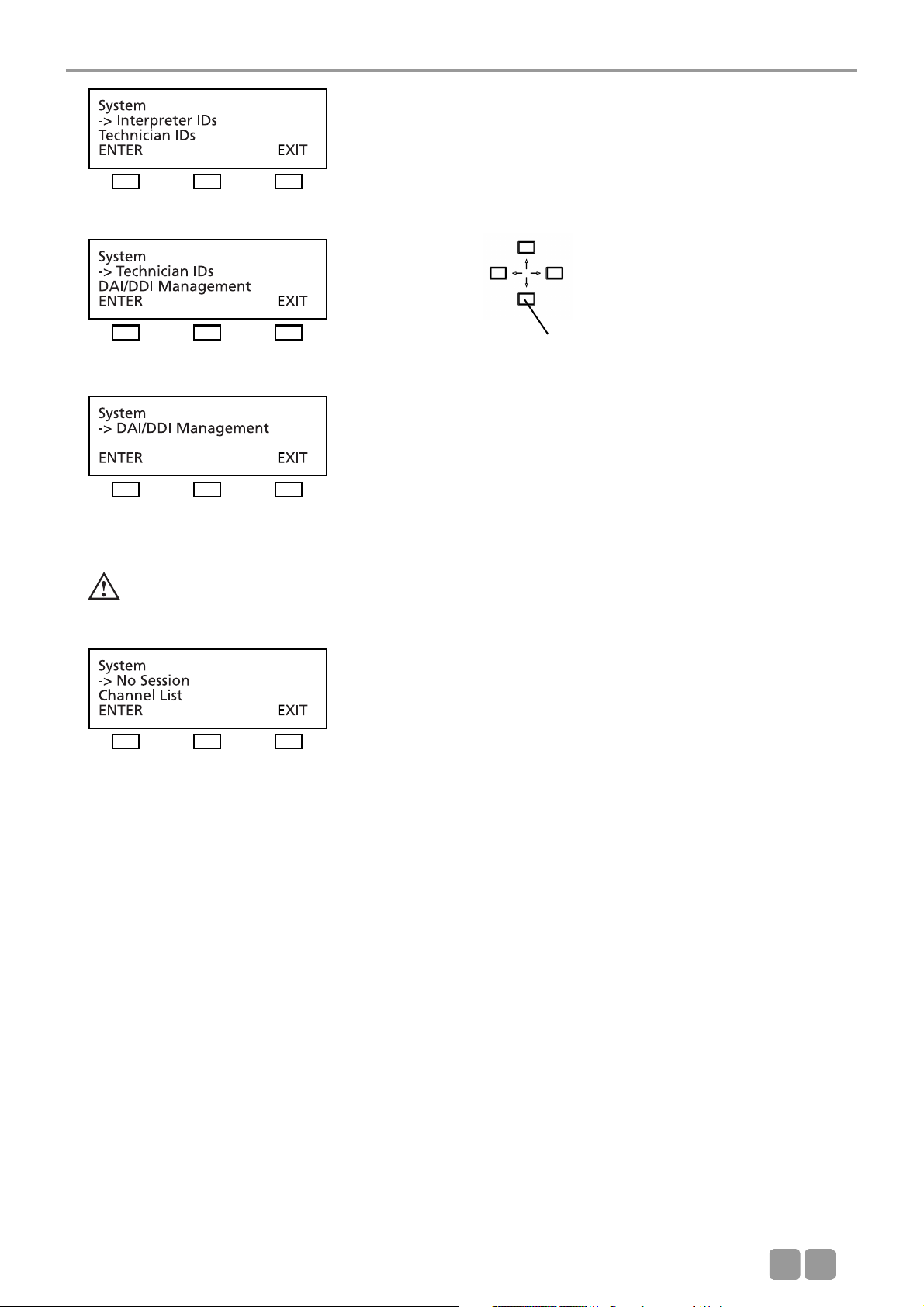
3.3.3 System set-up menus
Warning:
In systems using PC and iCNS software the settings are operated via the iCNS software. The set-up menus of the
MCS-D 200 control unit cannot be operated to avoid conflicts.
Note:
The SYSTEM SETUP menus are used for the settings of the system level = GLOBAL SYSTEM SETTINGS : Define Channels,
Message(s), Options, Delegate IDs, Interpreter IDs, Technician IDs and DAI/DDI Management. All devices, channels, messages
and options of the whole MCS-D 200 system are defined via these menus.
In the SESSION menus you can prepare settings for individual meetings.
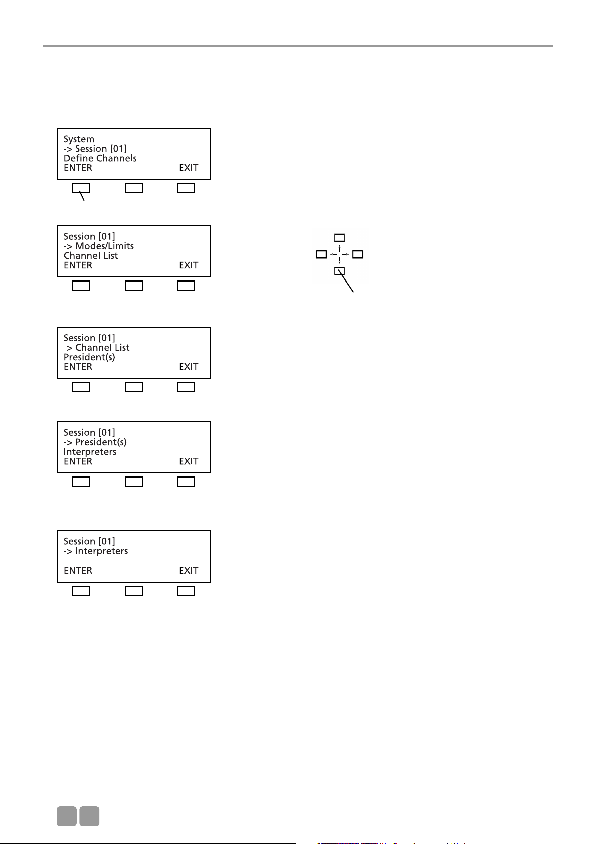
Press the SETUP buttons to access the SYSTEM menus. The arrow indicates the current line. Scroll through the menus by using
the up or down navigator buttons. Press the ENTER button to access the submenus. Change individual values by using the left
or right hand navigator buttons.
Use the up or down navigator
button for scrolling.
Page 15
MCS-D 200 Control Unit
E
15
Warning:
In systems using PC and iCNS software the settings are operated via the iCNS software. The set-up menus of the
MCS-D 200 control unit cannot be operated to avoid conflicts.
NO SESSION:
iCNS is in the offline mode (conference closed), not in the online mode (conference started).
Use the up or down navigator
button for scrolling.
Page 16
MCS-D 200 Control Unit
E
16
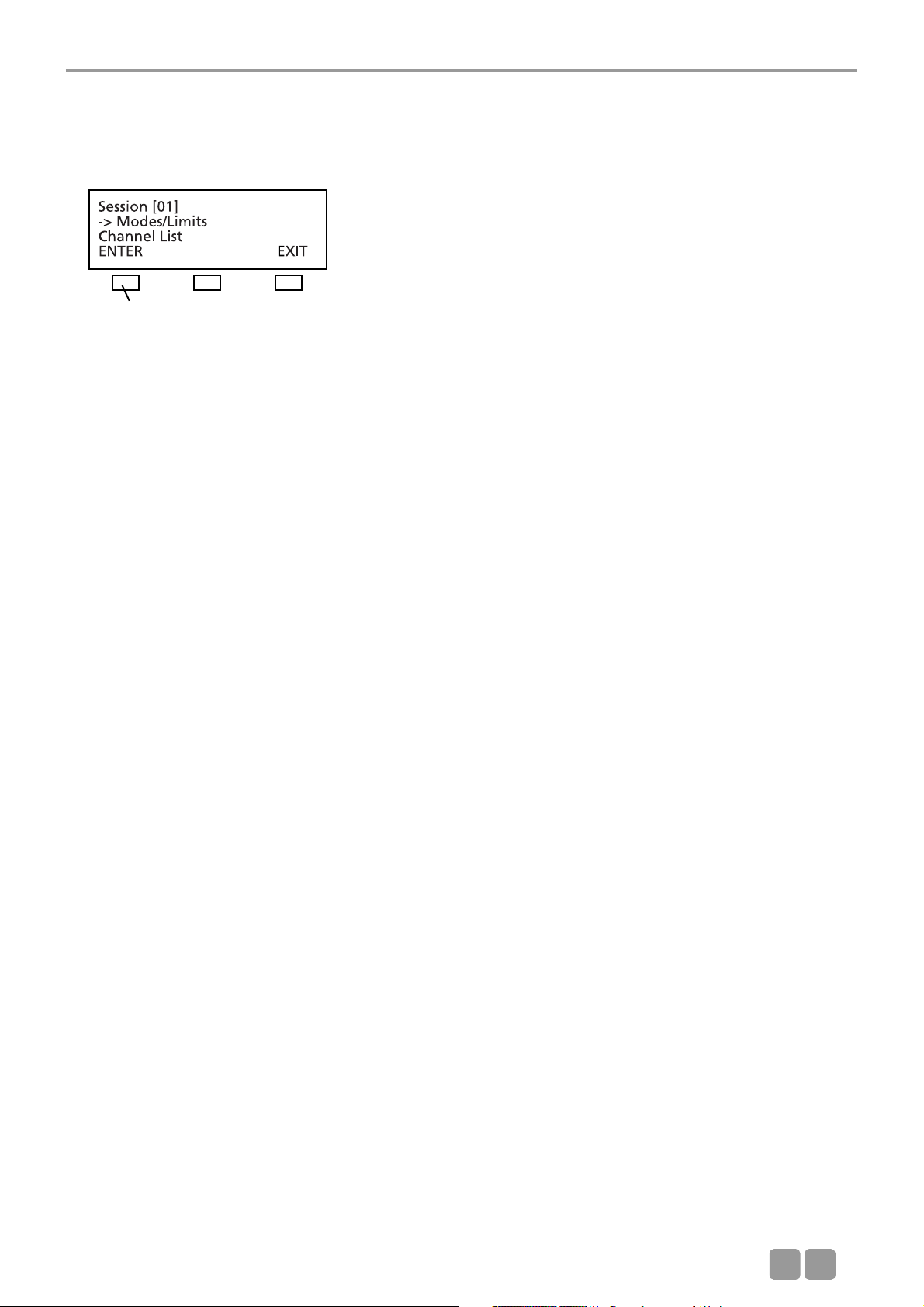
3.3.4 Session menus
In the SESSION menus settings for the meeting such as Mode/Limit, Channel List, Presidents, Interpreters are selected for the
meeting selected in the main menu.
Use the up or down navigator
button for scrolling.
press the ENTER button
Page 17
MCS-D 200 Control Unit
E
17
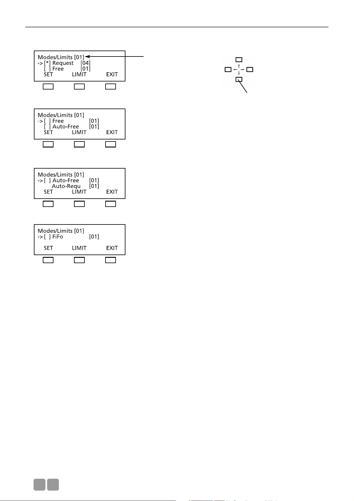
3.3.4.1 Mode / Limit menus
In the MODES/LIMITS menu you can enter the operating mode and number of open microphones (limit) for the selected session
(here it is session 01).
Free Mode
Each delegate can turn on the microphone of the microphone station if the selected number of open microphones (limit) is not
exceeded.
Limit - Free
Determine the maximum number of open microphones. The maximum number is 16.
Request Mode
Delegates enter a request-to-speak by pressing the microphone button. The request-to-speak is registered if the number of
possible requests to speak (limit) is not exceeded. By pressing the “0” button the chairman can release the registered requestto-speak.
Limit - Request
Determine the maximum number of requests to speak. The maximum number is 16.
If the limit is set to 2 or higher, the microphones of the registered speakers are turned on simultaneously by pressing the “0”
button. If only one speaker is to speak, the limit of the Request mode must be set to 1.
Auto Mode
The request-to-speak/turning on of microphones is one after another. Each delegate can turn on his microphone by pressing
the microphone button if the selected limit is not exceeded. If the limit is exceeded, the request-to-speak is registered in the
MCS-D 200 control unit. The microphone unit is turned on automatically as soon as a current speaker turns off his microphone.
LIMIT - Auto-Free:
Determine the maximum number of open microphones. The maximum number is 16.
LIMIT - Auto-Request:
Determine the maximum number of simultaneous requests to speak. The maximum number is 16.
FIFO Mode (First In - First Out)
The microphones are turned on one after another. Each delegate can turn on the microphone of his microphone station by
pressing the microphone button. If the limit is exceeded, the microphone of the delegate speaking the longest is turned off
automatically (first in - first out).
LIMIT - FiFo:
Determine the maximum number of open microphones. The maximum number is 16.
Note:
If the rights of a chairman station are assigned to a microphone station via the MCS-D 200 control unit, the chairman can
control the meeting actively by using the following function buttons:
CANCEL button to cancel turned on microphones and/or requests to speak.
PRIORITY button to mute turned on microphones.
NEXT button = press the “0” button to select the next request-to-speak.
PREVIOUS button = press the “9” button to select the previous speaker.
press the ENTER button
Page 18
MCS-D 200 Control Unit
E
18
How to set Modes
To select the mode press the SET button. A star in brackets indicates the selected operating mode.
Use the up or down navigator
button for scrolling.
Session number
Page 19
MCS-D 200 Control Unit
E
19
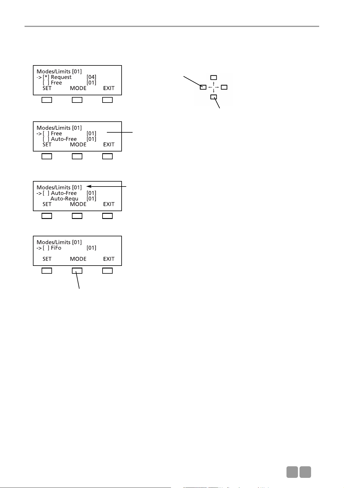
How to set the Limits
Press the LIMIT button to set the limit. Select the limit by using the right or left hand navigator buttons. Press the MODE
button to return to the MODE menu.
Change LIMIT:
Press the left or right hand
navigator button.
Use the up or down navigator
button for scrolling.
Cursor is flashing
Session number
Press MODE button to return
to the MODE menu.
Page 20
MCS-D 200 Control Unit
E
20
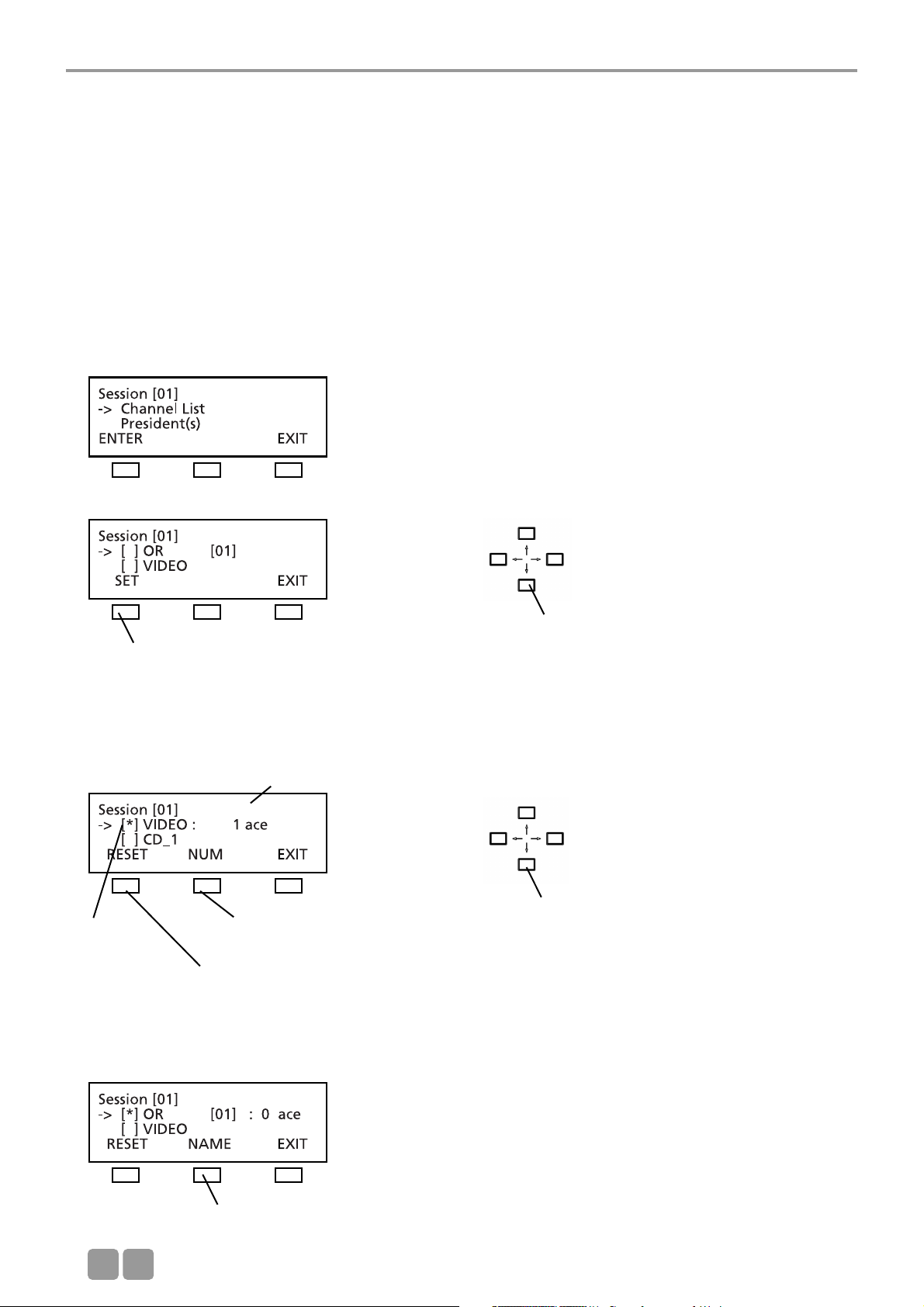
3.3.4.2 Channel List
In the menu CHANNEL LIST you can prepare and edit a list of all required channels. All channels have to be defined in the
menu DEFINE CHANNELS (refer also to the chapter 3.3.5 “Define Channels”), because the channel list is basing on the
predefined channels.
Whenever the delegate presses the language/channel selector button of his microphone station, the list is displayed.
The channel list includes the OR channel, language channels or other channels such as music channels.
For the interpreter stations you can select channels from this channel list.
In the menu CHANNEL LIST you can...
1. ...scroll through the channel list with all predefined channels of the whole system.
2. ...prepare a channel list for the selected session:
• select required channels (set/reset)
• name and number channels
Note: Channels are added by pressing the SET button. A channel description consists of a maximum of 3 characters. The
language channels are encoded according to the international MARC language code (refer to chapter 11. “List of Language
Codes”).
Use the up or down navigator buttons to scroll through the list of all predefined channels in the menu DEFINE CHANNEL. Press
the SET button to add a selected channel to the channel list. The star * identifies the selected channel.
When the NUM button is pressed the cursor goes to the channel number. Use the up or down navigator button to change the
number.
Use the up or down navigator
button for scrolling.
Press the SET button to add OR channel to the channel
list
Use the up or down navigator
button to change the channel
number
The star *
identifies
the selected
channel
Press the RESET button to remove
selected channel from the channel
list
Press the NUM button to change
the number
Press the NAME button to change the channel
description
Adapt the number and description for the MCS-D 2073
display
Page 21
MCS-D 200 Control Unit
E
21
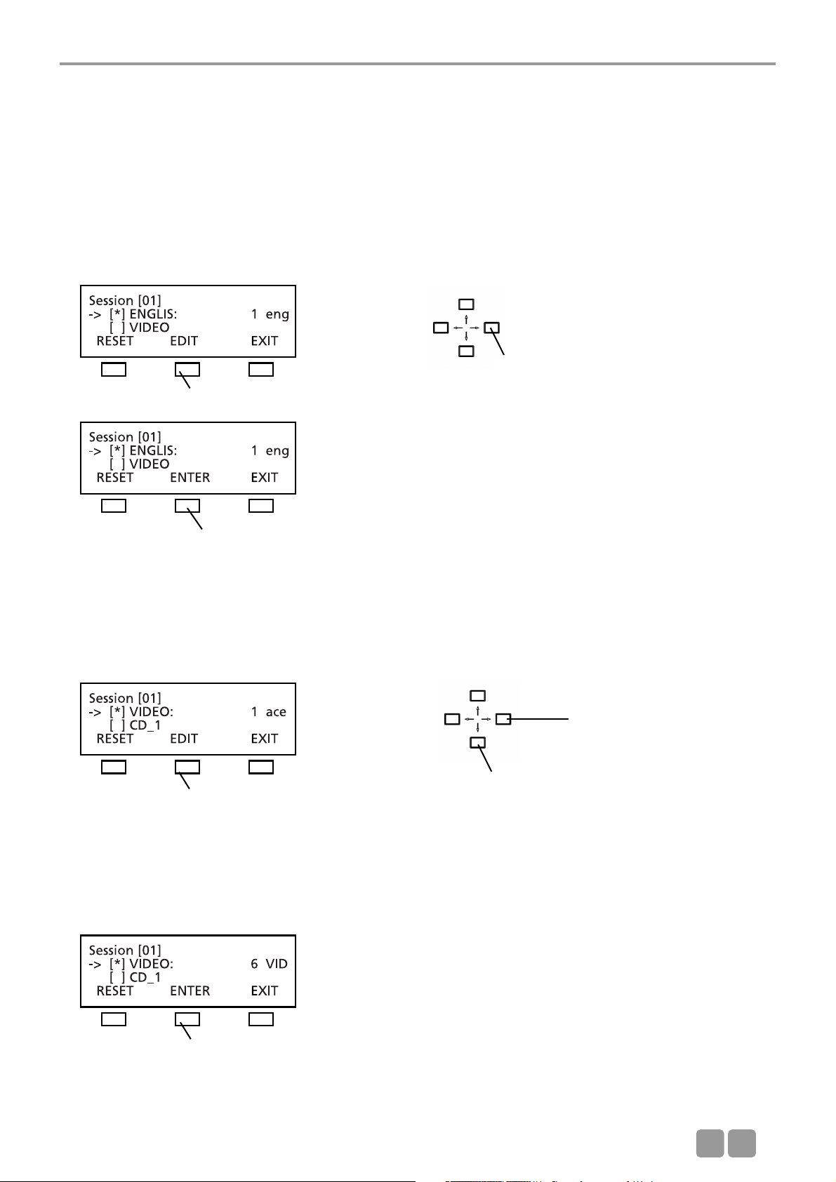
When the NAME button is pressed, the cursor goes to the channel description (refer to illustration). The description can be
changed as described in the following:
Note:
1. By pressing the right or left hand navigator buttons you can assign a code of the international language list to a language
channel (refer to chapter 11. “List of Language Codes”).
2. For other channels you can create another description with a maximum of three characters from a predetermined list. Move
the cursor to the position with the left or right hand navigator buttons and scroll through the list of characters with the up
and down navigator buttons.
A code of the international language list is assigned to a language channel:
For any other channel you can select a maximum of 3 characters from a list:
When the EDIT button is pressed, the cursor goes to the first choice. Use the up or down navigator button to select a character
from the list. Then use the right or left hand navigator button to move the cursor to the next choice etc.
Use the right or left hand navigator button
to scroll through the international language
list.
press the EDIT button
press the ENTER button to confirm
press the EDIT button
Use the up or down navigator button to
scroll through the list to select the desired
character
Use the right or left hand
navigator button to move
the cursor to the next position
press the ENTER button
Page 22
MCS-D 200 Control Unit
E
22
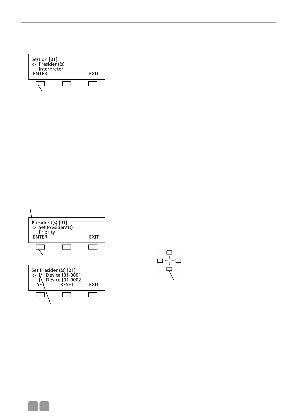
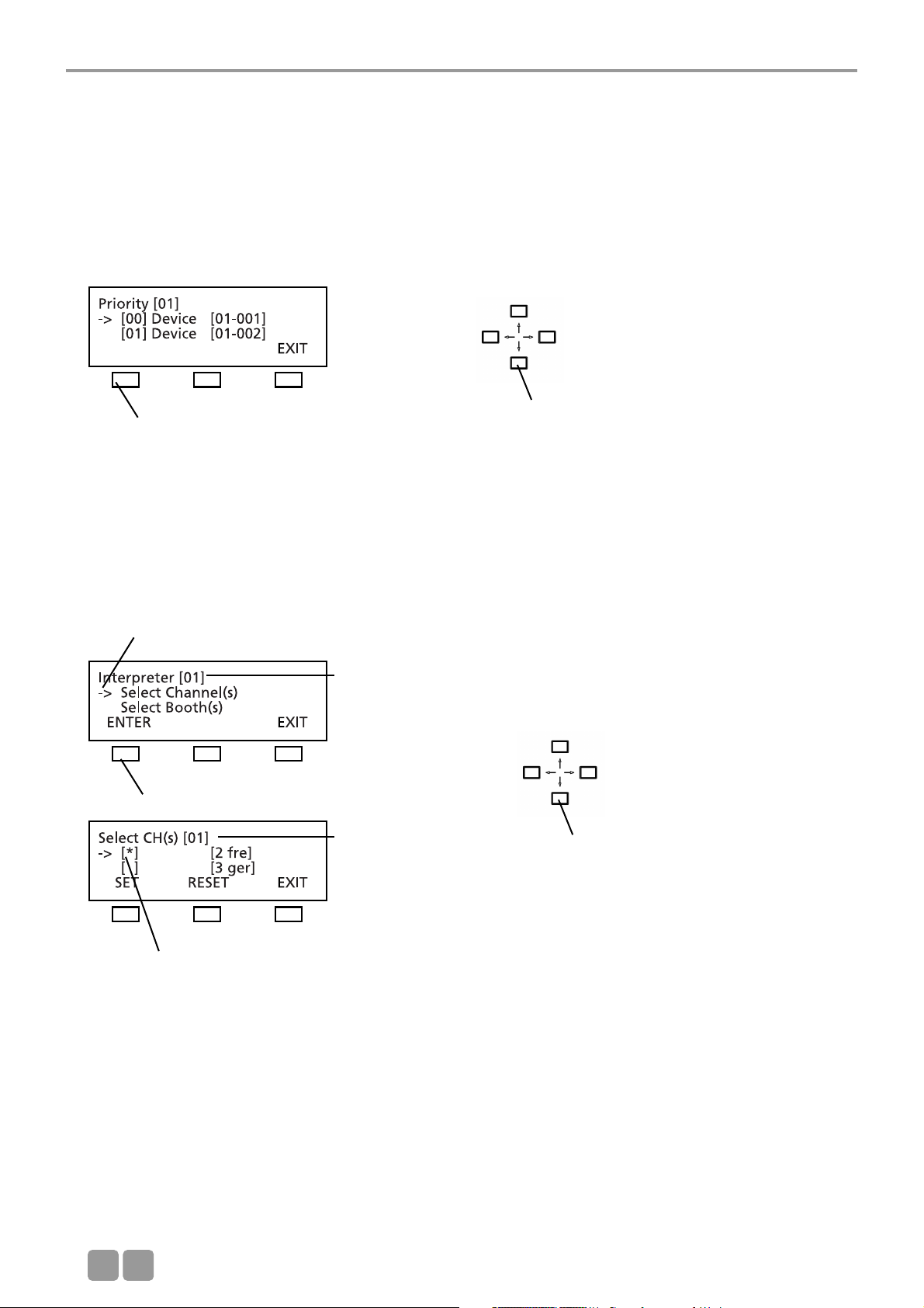
3.3.4.3 President(s)
In the PRESIDENTS menu you can assign the functions of a chairman station such as CANCEL, PRIORITY, PREVIOUS or NEXT to
any microphone station in the selected session (here: session 01).
The following items refer to chairman stations:
• Each chairman can turn on his microphone at any time, regardless of the selected limit.
• Any number of microphone stations can be programmed as chairman stations.
• Chairman stations can be assigned to different levels (0-99), each level with any number of chairman stations.
• By using the PRIORITY button the chairmen of a higher level can mute all microphones of the delegate stations and the
chairman stations of a lower level.
• Chairman stations of the same level, however, cannot be muted by using the PRIORITY button.
• Depending on the operating mode, all chairmen can turn off the microphones of all delegate stations by using the CANCEL
button.
• By using the NEXT button chairman can release requests to speak and by using the PREVIOUS button they can ask previous
speakers to speak once again.
How to program Chairman Stations (SET/RESET)
Each delegate station features a device ID number (refer to chapter 3.3.7 “Delegate IDs” and 3.3.7.2 “Set IDs”). Use the up or
down navigator button to scroll to the microphone station with the appropriate ID which is to be programmed as a chairman
station. The arrow indicates the selected microphone station. Then press the SET button to assign the functions of a chairman
station to this microphone station. In this way you can program any number of microphone stations as chairman stations. The
star in brackets identifies all chairman stations.
If you would like to cancel the chairman functions of a microphone station, use the up or down navigator button to scroll to
the microphone station with the appropriate ID. The arrow indicates the selected microphone station. Press the RESET button
to cancel the chairman functions of the selected microphone station. The star is removed.
Press the EXIT button when all chairman stations are determined. In the PRIORITY LEVEL(S) menu you can then assign the
chairman stations to different levels.
press the ENTER button
The arrow indicates the active line.
press the ENTER button
The star indicates the chairman station
Session number
Device ID
Use the up or down navigator button to
scroll through the menu
Page 23
MCS-D 200 Control Unit
E
23
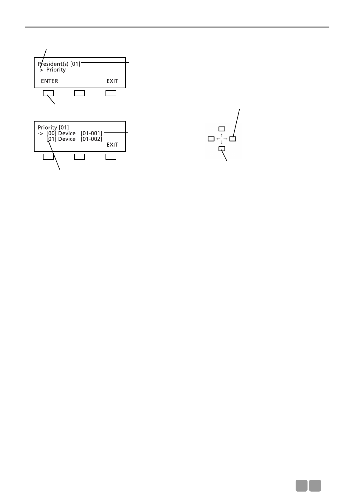
PRIORITY LEVEL(S) for Chairman Stations
All microphone stations which have been programmed as chairman stations in the SET PRESIDENT(s) menu are listed here. You
can assign a level to each chairman station. “0” is the highest level, “99” the lowest. For each level any number of microphone
stations is possible. The standard setting is level “0”. If you want to select a different level for a microphones station, use the
up or down navigator button to choose the microphone station. Then use the right or left hand navigator button to change
the level.
In the example above the chairman station 0001 is on a higher level than the chairman station 0002. If the chairman holds
down the PRIORITY button of the microphone station 0001, the microphone of the chairman station 0002 is muted along with
the delegate stations.
Use the up or down navigator
button for scrolling
Use the right or left hand
navigator button to change the
level
The arrow indicates the active line.
session number
press the ENTER button
Device ID
Level 0-99
Page 24
MCS-D 200 Control Unit
E
24
3.3.4.4 Interpreter
In the INTERPRETER menu you can prepare a list of all required interpreter’s channels from the list of session channels for the
selected session (here: session 01) (refer also to chapter 3.3.4.2 “Channel List”). The list includes only channels required for
interpreters, i.e. all channels for the preselection of the relay and output channels.
When the relay channel or PRE SELECT output channel button of the MCS-D 202 interpreter station is pressed, the list of the
interpreter channels is displayed.
Then select from the booth list all booths required for the selected session (refer to chapter 3.3.7.1 “ID List”).
How to prepare the list of interpreter’s channels for the session
In the INTERPRETER menu you can prepare a list of all required interpreter’s channels from the list of the session channels
(refer to chapter 3.3.4.2 “Channel List”) for the selected session (here: session 01).
Use the up or down navigator button to select the channel which is to be added to the interpreter’s channel list. Then press
the SET button. The star identifies the selected channel. Repeat these steps to add more channels to the list.
Press the RESET button if you want to remove a selected channel from the interpreter’s channel list. The star is removed.
Repeat these steps if you want to remove more channels from the interpreter’s channel list.
Press the EXIT button to leave this menu.
press ENTER button
The arrow indicates the active line.
Session number
press the ENTER button
The star identifies the selected channel.
Session number
Use the up or down navigator button to
scroll through the menu
Use the up or down navigator button to
scroll through the menu
Page 25
MCS-D 200 Control Unit
E
25
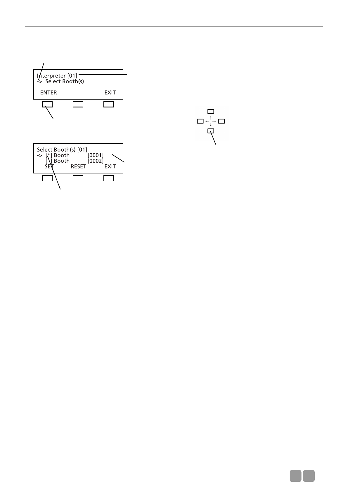
How to select the required interpreter’s booth(s) for the session
Select all booths required for the selected session from the booth list (refer to chapter 3.3.7.1 “ID List”).
Use the up or down navigator button to select the booth required for the session (here: 01). Then press the SET button. The
star identifies the selected booth. Repeat these steps to select more booths.
To remove a selected booth from the session press the RESET button. The star is removed. Repeat these steps if you want to
remove more booths from the session.
Press the EXIT button to leave the menu.
The arrow indicates the active line.
Session number
Booth number
press the ENTER button
The star identifies the selected booth.
Use the up or down navigator button to
scroll through the menu
Page 26
MCS-D 200 Control Unit
E
26
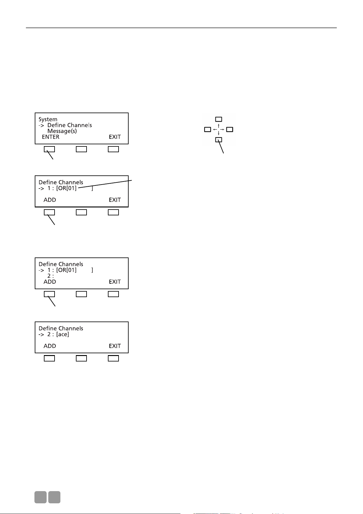
3.3.5 Define Channels
In the DEFINE CHANNELS menu all channels required for the whole system are defined, added or removed. By using these
defined channels the lists of the session channels are prepared for the individual sessions (refer to chapter 3.3.4.2 “Channel
List”).
Note:
• The OR channel does always exist in the list and may neither be edited nor deleted.
• A channel currently in use may neither be edited nor deleted.
Press the ADD button to add a new channel.
Note:
1. For language channels you may select a name from an international language code list (refer to chapter 11. “List of
Language Codes”) by using the right or left hand navigator button.
2. For any other channel you may edit the code (up to 3 characters). By using the right or left hand navigator button you can
place the cursor at the desired position and by using the up or down navigator button you can scroll through a list of
characters.
3. A defined channel may comprise a maximum of 6 characters.
Use the up or down navigator button to
scroll through the menu
press the ENTER button
press the ADD button
OR channel of session 1
press the ADD button
Page 27
MCS-D 200 Control Unit
E
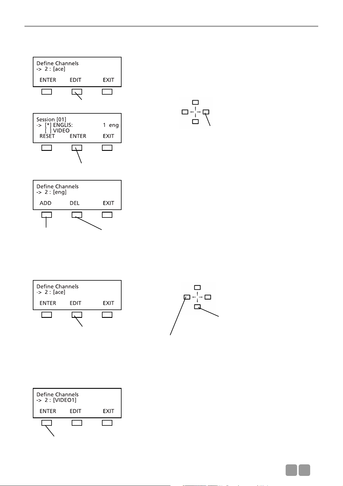
27
For a language channel select the name from a list of international language codes (refer to chapter 11. “List of Language
Codes”):
For any other channel which does not receive an international language code, you can select individual characters from a list of
characters:
When the EDIT button is pressed the cursor goes to the first position. Use the up or down navigator button to select a character
from the list. Use the right or left hand cursor button to go to the next position etc.
Use the right or left hand navigator button
to scroll through the list of language codes
press the EDIT button to open the channel list
press the ENTER button to confirm
press the ADD button to
define a new channel
press the DEL button to
delete a channel
press the EDIT button
press the ENTER button to confirm
Use the up or down navigator button
to scroll through the list to find the
desired character
Use the right or left hand navigator
button to go with the cursor to the
next character position
Page 28
MCS-D 200 Control Unit
E
28
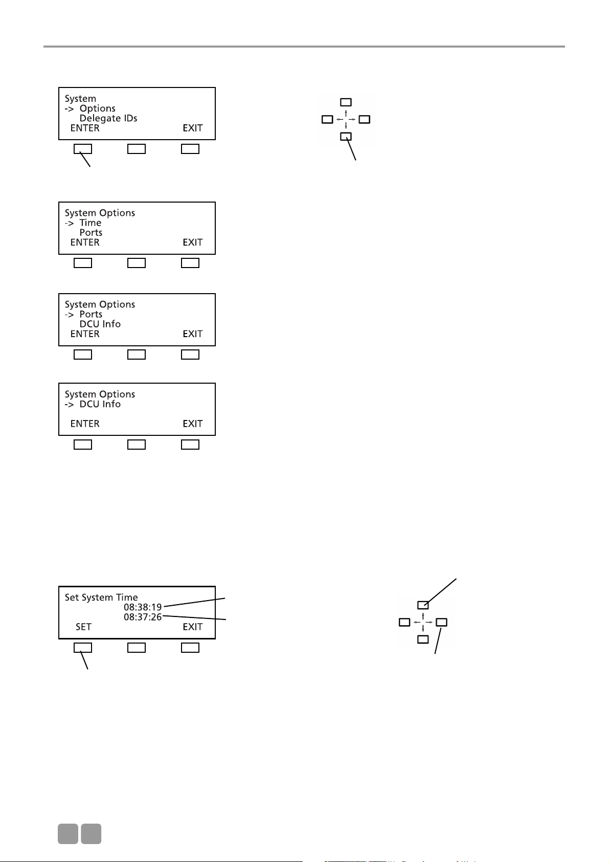
3.3.6 Options
3.3.6.1 Time
In the TIME menu the system time for the MCS-D 200 control unit, MCS-D 202 and MCS-D 2073 microphone stations can be set
manually (refer to chapter 7.1.6 “Menu settings”) in the format HOURS – MINUTES – SECONDS.
When the iCNS software is started, the system time is refreshed automatically.
The current system time is displayed in the CURRENT TIME line as:
HOURS : MINUTES : SECONDS.
You can change the time in the line below. Use the right or left hand navigator button to go from HOURS to MINUTES and
SECONDS. Use the up or down navigator button to set the new values and press the SET button to confirm.
press the ENTER button
Use the up or down navigator button for
scrolling
Current time setting
Refreshed time setting
press the SET button to confirm
Use the right or left hand navigator button
to go from HOURS to MINUTES and SECONDS
Use the up or down
navigator button to
edit the numbers
Page 29

MCS-D 200 Control Unit
E
29
3.3.6.2 Ports
The RS-232C(1) Port and RS232C(2) Port are configured to connect to a PC with the iCNS software or to a media control
system.
Use the up or down navigator button to go to COM 1 or COM 2. Use the right or left hand navigator button to scroll through
the configuration list.
3.3.6.3 MCS-D Info
Use the right or left hand navigator button
to scroll through a configuration list
Press the up or down navigator button to
select a COM port
14 15
Page 30

MCS-D 200 Control Unit
E
30
3.3.7 Delegate IDs
For identifying a device identification number (ID) should be assigned to each delegate station. Basically, the system can be
operated without the organisation of ID numbers. But for special functions such as functions of a chairman station, phoning
and some data bank manangement functions the organisation of the IDs of the microphone stations is absolutely necessary for
a smooth meeting. In order to avoid conflicts each ID number can be assigned only once. For the telephone function, e.g. the
ID numbers are used as device telephone numbers which will appear in a telephone list in the menu.
Addressing is defined as assigning an individual number to a certain device - for example – delegate station no. 1 shall be
ID-no. 0001, delegate station no. 2 shall be ID-no. 0002, and so on.
Use the up or down navigator button for
scrolling
press the ENTER button
Page 31

MCS-D 200 Control Unit
E
31
3.3.7.1 ID List
You may assign an ID to individual devices. Also refer to chapter 3.3.7.2 “Set IDs” to find out how you can set IDs for all
microphone stations.
Scroll to the “GROUP” line. Use the right or left hand navigator button if you want to change the group number.
Note:
In the stand-alone mode (if you do not use the iCNS software) all microphone stations are assigned to the same session, no
matter to which group they belong. An assignment to groups is only possible in the MultiSession mode when using the iCNS
software.
Now use the down navigator button to go to the “DEVICE ID” line. The LED ring of the selected microphone station will
illuminate (here: microphone station 1 out of 50).
Use the right or left hand navigator button to assign a DEVICE ID number (1 to 2000). If you select an ID number which has
been already assigned, hash will be diplayed. In this case select a different number to avoid conflicts. Microphone stations of
different groups can have the same ID; for example the microphone stations of group 1 have the IDs 0001 to 0200 and the
microphone stations of group 2 have the IDs 0001 to 0150.
Select the next microphone station, and so on.
Use the up or down navigator button for
scrolling
press the ENTER button
Group number
Device Identification number (ID)
Hash indicates that the ID number has been
already assigned to another device. Select a
different number!
Press the SET ID button if the device has the
desired number.
Use the right or left hand navigator button
to edit the number
Page 32

MCS-D 200 Control Unit
E
32
3.3.7.2 Set IDs
This function allows you to set identification numbers for all microphone stations by pressing the MIC button of all microphone
stations one after the other.
Go to the “Group” line. Use the right or left hand navigator button to change the session number, if necessary.
Note:
In the stand-alone mode (if you do not use the iCNS software) all microphone stations are assigned to the same session, no
matter to which group they belong. Microphone stations can be assigned to different groups only when using the iCNS
software in the MultiSession mode.
Use the down navigator button to go to the “DEVICE ID” line. Use the right or left hand navigator button to enter the first
ID number.
Then press the microphone button of the first microphone station to assign the first ID number to this microphone station.
The LED ring will illuminate and the display of the microphone station will show the ID number. Press the microphone button
of the second microphone station. The LED ring will illuminate and the next ID number will be shown on the display of the
microphone station. Continue like this to assign ID numbers to all microphone stations one after another.
Refer to the previous chapter to find out how to assign individual ID numbers.
3.3.7.3 Conflicts
For identifying a device identification number (ID) should be assigned to each delegate station. To avoid conflicts each ID
number may be assigned only once.
Use the up or down navigator button for
scrolling
press the ENTER button
Device identification number
press the ENTER button
The arrow indicates the active line
Use the right or left hand navigator button
to enter the first ID number.
Page 33

MCS-D 200 Control Unit
E
33
3.3.8 Interpreter IDs
For identifying a device identification number (ID) should be assigned to each intepreter station. Basically, the system can be
operated without the organisation of ID numbers. But for special iCNS software and service monitoring functions the organisation
of the IDs of the interpreter stations is absolutely necessary for a smooth meeting. The ID number for an interpreter station
consists of the booth ID and device ID. In order to avoid conflicts each ID number can be assigned only once. For different
booths you may assign the same device IDs.
For example:
Booth 1: MCS-D 202 (1) = 01-0001, MCS-D 202 (2) = 01-0002
Booth 2: MCS-D 202 (1) = 02-0001, MCS-D 202 (2) = 02-0002
Use the up or down navigator button for
scrolling
press the ENTER button
Page 34

MCS-D 200 Control Unit
E
34
3.3.8.1 Interpreter ID List
You may select an individual device and assign a booth in combination with a device dentification number (DEVICE ID). Also
refer to chapter 3.3.8.2 “Set Interpreter IDs” to find out how you can assign identification numbers to all interpreter stations.
Go to the “Booth” line and enter the booth number. Then use the down navigator button to go to the “Device ID” line. The
LED ring of the selected microphone station will illuminate (here: microphone station 1 out of 2).
Use the right or left hand navigator button to enter a device ID number (1 to 2000). If you select an ID number which has been
already assigned, hash will be diplayed. In this case select a different number to avoid conflicts.
The same ID number can be assigned to interpreter stations in different booths.
Example:
Booth 0001: Interpreter station no. 0001, 0002;
Booth 0002: Interpreter station no. 0001, 0002.
Select the next interpreter station, and so on.
3.3.8.2 Set Interpreter IDs
With this function you can assign device IDs to all microphone stations in one booth by pressing the MIC button of the
microphone stations one after another.
Note: You can directly assign IDs to the MCS-D 202 interpreter station. Refer also to chapter 7.2.7 “How to assign an ID to the
interpreter station”.
Use the up or down navigator
button for scrolling
Use the right or left hand
navigator button to change
the number
Booth number
Device identification number (ID)
Hash indicates that the ID number has been
already assigned to another device. Select a
different number!
Press the SET ID button if the device has the
desired number.
press the ENTER button
press the ENTER button
Use the up or down navigator button for
scrolling
Use the right or left hand navigator button
to enter the first ID number!
Booth number
Device ID number
Page 35

MCS-D 200 Control Unit
E
35
Go to the “Booth” line and enter the booth number. Then use the down navigator button to go to the “Device ID” line. Use
the right or left hand navigator button to enter the first interpreter station ID number.
Then press the MIC button of the first interpreter station to assign the first ID number to this microphone station. The LED ring
will illuminate and the ID number will be shown on the display of the microphone station.
Then press the microphone button of the second interpreter station. Then press the microphone button of the second interpreter
station. The LED ring will illuminate and the next ID number is shown on the display of the interpreter station and on the
MCS-D 200 control unit. Proceed with the next interpreter station as described above and so on.
Assign the ID numbers to all interpreter stations in the same booth.
To assign the ID numbers to the second booth go to the “Booth” line and enter the second booth number. Assign the ID
numbers to the interpreter stations as described above.
You may assign the same device ID numbers if the interpreter stations are in different booths.
For example:
Booth 0001: Interpreter station no. 0001, 0002;
Booth 0002: Interpreter station no. 0001, 0002.
Refer to the previous chapter to find out how individual ID numbers are assigned.
3.3.8.3 Conflicts
A device identification number should be assigned to each interpreter station to identify them easily. Please make sure that
each ID number is only assigned once within the same session to avoid conflicts.
3.3.9 Technician IDs
To enter an ID for the MCS-D 2074 service microphone station proceed as described in chapter 3.3.7 “Delegate IDs”.
press the ENTER button
Use the up or down navigator button for
scrolling
press the ENTER button
Page 36

MCS-D 200 Control Unit
E
36
3.3.10 DAI/DDI Management
The MCS-D 200 control unit features an integrated D/A interface (=INTERNAL DAI) with the connexions CH1 IN, CH2 IN,
CH1 OUT and CH2 OUT.
To provide more analogue inputs and outpus, additional Digital / Analog Interfaces (DAI) are connected via the conference
bus for the connection of external audio devices such as wireless microphones or tape recorders providing the sound of a
video film in different languages. The 19" housing of a Digital / Analog Interface (DAI) may be equipped with a maximum of
3 interface units (=EXTERNAL DAI), each with 2 analogue audio inputs and outpus. The DAI is powered via the system and is
recognised when the system is started.
In the DAI/DDI MANAGEMENT menu you can set the following:
DAI Management:
• Set an identification number (logical address) for each external DAI.
• Assign channels to the LINE INPUTS and LINE OUTPUTS of the internal and external DAIs.
DAIs are operated as described in the following:
• Set the level of all LINE IN and LINE OUT channels of the internal and external DAIs.
• Switch on/off all LINE IN and LINE OUT channels of the internal and external DAIs.
Warning:
Unused DAI inputs must be OFF, to avoid noise!
DDI Management:
• Assign channels to digital outputs
DDIs are operated as described in the following:
• Switch on/off all outputs.
The DAI/DDI Management menus include the Ext. DEVICE LIST, DAI SETUP and DAI CONTROL menus.
Use the up or down navigator button for
scrolling
press the ENTER button
Page 37

MCS-D 200 Control Unit
E
37
3.3.10.1 Ext. DAI ID List
In the Ext. DAI ID LIST menu you may enter a device identification number (logical address) for every interface unit (=EXTERNAL
DAI), that is an interface unit with 2 CH IN and 2 CH OUT each. Each interface unit is regarded as an independent device, even
if there is a maximum of 3 interface units in the same 19" housing of one DAI. The interface units are recognised when the
system is started.
The identification number of the internal D/A interface of the MCS-D 200 control unit (=INTERNAL DAI) is fixed [=00] and
cannot be changed.
3.3.10.2 DAI Set-up
In the DAI SETUP menu you may assign channels to the LINE INPUTS and LINE OUTPUTS of the internal and external DAIs.
The DAI SETUP menu includes a list of the internal D/A interfaces of the MCS-D 200 control unit [=00] and all external DAI
units; each with its ID number that has been set in the EXT. DAI ID LIST menu.
The identification number of the internal DAI of the MCS-D 200 control unit is fixed and cannot be changed.
Use the up or down navigator button to scroll through the list. Use the ENTER button to select a DAI for assigning channels.
The LED on the front of the DAI interface will illuminate for the selected D/A unit.
Use the up or down navigator button
for scrolling
Use the right or left hand
navigator button to enter the
new ID number!
press the ENTER button
press the SET ID button to confirm
EXTERNAL DAI 1 (of 3 DAIs); the appropriate
LED will illuminate on the front of the DAI
Hash indicates that the ID number has
been already assigned to another device.
Select a different number!
press the ENTER button
Internal DAI [=00] of the control unit
Use the up or down button for
scrolling
Page 38

MCS-D 200 Control Unit
E
38
Each DAI unit features CH1 IN, CH 2 IN; CH 1 OUT, CH 2 OUT
Scroll through the list of channels which has been defined in the DEFINE CHANNELS menu before.
Press the ADD button to confirm the selected channel. You can select and add another channel or press the EXIT button.
press the ENTER button, to assign channels to DAI no. 01
External DAI no. 01
press the ENTER button for CH 1 OUT
press the ADD button
Use the up or down navigator button
for scrolling
Use the right or left hand
navigator to scroll through the
list of defined channels!
Page 39

MCS-D 200 Control Unit
E
39
3.3.10.3 DAI Control
The DAI CONTROL is operated as described in the following:
• Switch on/off all LINE INPUTS and LINE OUTPUTS of the internal and external DAIs.
Warning:
Unused DAI inputs must be OFF, to avoid noise!
• Adjust the level of all LINE INPUTS and LINE OUTPUTS of the internal and external DAIs
The DAI CONTROL menu includes a list of the internal and external DAIs; each with its ID number that has been set in the EXT
DAI ID LIST (refer also to chapter 3.3.10.1 “Ext. DAI ID List”.
The identification number [=00] of the internal DAI of the MCS-D 200 control unit is fixed and cannot be changed.
Use the up or down navigator button to scroll through the list. Use the ENTER button to select the DAI. The LED of the
selected D/A unit will illuminate on the front panel of the DAI.
Each DAI unit features CH1 IN, CH 2 IN; CH 1 OUT, CH 2 OUT
INTERNAL DAI level EXTERNAL DAI level
IN: -28.5 dB…+18 dB IN: -9.5 dB…+13 dB
OUT: -78 dB…+16.5 dB OUT: -24 dB…+22.5 dB
press the ENTER button
internal DAI
external DAI no. 01
press the ENTER button for the DAI no. 01
Use the up or down navigator button
to scroll through the device list
Use the up or down navigator button
to scroll through the CH list
Page 40

MCS-D 200 Control Unit
E
40
How to switch off a channel:
Warning:
Unused DAI inputs must be OFF, to avoid noise!
How to switch on a channel:
How to set the level:
press the ENTER button for CH 1 OUT
press the OFF button
press the ON button
INTERNAL DAI level EXTERNAL DAI level
IN: -28.5 dB…+18 dB IN: -9.5 dB…+13 dB
OUT: -78 dB…+16.5 dB OUT: -24 dB…+22.5 dB
Page 41

CA 4115/30/45 Power Supply Unit
E
41
4. CA 4115/30/45 Power Supply Unit
The MCS-D 200 control unit features a modular power converter for approximately 15 microphone stations (MCS-D 202 or
MCS-D 2073); optionally two power converters for approximately 30 microphone stations.
If the system is to be extended, you will require additional power supply units.
The following power supply units are supplied for installation into a 19" rack.
CA 4115 power supply unit (1 modular power converter = 2 A) for approx. 15 microphone stations
CA 4130 power supply unit (2 modular power converters = 4 A) for approx. 30 microphone stations
CA 4145 power supply unit (3 modular power converters = 6 A) for approx. 45 microphone stations
Note:
Before connecting any devices, always make sure which type of power supply unit you are using. You will find the designation
on the type plate on the back panel of the power supply unit.
4.1 Controls and indicators
Front view
Power switch
Power LED illuminates when the MCS-D 200 control unit is switched on and ready to pass signals, no matter if the
power switch is on or off.
Power converter LED 1-3. These LEDs will only illuminate when the MCS-D 200 control unit and the power supply unit are
switched on.
Ventilation slots must not be covered to provide unrestricted circulation.
Mounting brackets for installation into a 19" rack.
1
1
1
2
3
4
5
245 3
Rear view
Mains connector with fuse holder. The fuse holder contains a 6.3 A slow-blow (T) fuse.
Ventilation outlet. The fan is controlled by the temperature.
NetRateBus sockets to connect the MCS-D 200 control unit or CA 4115/30/45 power supply unit.
Extension ports to connect microphone stations such as MCS-D 202, MCS-D 2073 etc.
6
6 8
7
7 9
8
9
Page 42

CA 4115/30/45 Power Supply Unit
E
42
4.2 Connection
4.2.1 Control unit – power supply unit
• The MCS-D 200 control unit and the power supply unit are connected via the NetRateBus socket . Refer also to chapter 8.
“Set-up examples”.
Warning: Connected devices (e.g. adapters or Digital/Analog interfaces) are powered by the MCS-D 200 control unit and
have to be considered in power calculations.
• Each unit which is connected to a NetRateBus socket is powered by the MCS-D 200 when it is switched on. It is not important
if the power supply unit is switched on or off. A Digital/Analog interface or adapter connected to the NetRateBus sockets
would be powered by the power converter of the MCS-D 200. These sockets are not the power outputs for the microphone
stations, adapter or interfaces.
4.2.2 Microphone stations - power supply unit
• Connect microphone stations, Digital/Analog interfaces and adapters to the EXTENSION PORTS angeschlossen.
• Any device which is connected to an EXTENSION PORT, is powered by the power converters 1-3 of the CA 4115/30/45 power
supply unit, when the MCS-D 200 control unit and the power supply unit are switched on. This is indicated by the illuminated
LEDs 1-3.
4.3 How to switch on the power supply unit
• Check all connections before switching on.
• Stand-by: A switched-on power supply unit is in stand-by mode when the mains switch is illuminated, but the power
converters 1-3 cannot emit power via the EXTENSION PORTS , because the MCS-D 200 control unit is not yet switched on.
In this case neither the “POWER” LED nor the power converter LEDs 1-3 will illuminate.
• We recommend switching on the devices as described in the following:
1. Switch on all power supply units first. The mains switch will illuminate and indicate the stand-by mode.
2. Switch on the MCS-D 200 control unit. The “POWER” LED of the MCS-D 200 will illuminate.
Then the “POWER” LED of each power supply unit will illuminate.
• Then the power converters 1-3 can emit power via the EXTENSION PORTS . The illuminated power converter LEDs 1-3
display the appropriate power supply unit:
LED 1 CA 4115 (1 power converter for 2 A)
LED 1 + 2 CA 4130 (2 power converters for 4 A)
LED 1 + 2 + 3 CA 4145 (3 power converters for 6 A).
• The green Power-LED of the power supply unit will illuminate when the MCS-D 200 control unit is switched on and a bus
signal is produced, no matter if the mains switch of the power supply unit is switched on or off.
• The LEDs indicate the following:
GREEN: OFF:
- the MCS-D 200 control unit is switched on
- the power supply unit is switched on
- the power converter emits power via the EXTENSION
PORTS
- the MCS-D 200 control unit is switched off
- the power supply unit is switched off
- the power converter is not installed or defective
8
9
9
1
2
2
2 3
9
3
2
1
Page 43

CA 4522/44/66 Digital/Analogue Interface
E
43
5. CA 4522/44/66 Digital / Analogue Interface (DAI)
You may connect additional Digital / Analogue Interfaces (DAI) via the conference bus for the connection of external audio
devices such as wireless microphones or tape recorders providing the sound of a video film in different languages. The 19"
housing of a Digital / Analogue Interfaces (DAI) may be equipped with up to 3 interface units (=EXTERNAL DAI), each with
2 analogue audio inputs and outputs. The DAI is powered by the system power supply and is recognised upon system start:
(CA 4522: 1 x (2 IN / 2 OUT); CA 4544: 1 x (4 IN / 4 OUT); CA 4566: 1 x (6 IN / 6 OUT).
In the DAI/DDI MANAGEMENT menus you can adjust the following:
• Set an identification number (logical address) for every external DAI
• You can assign channels to the LINE INPUTS and LINE OUTPUTS of the INTERNAL and EXTERNAL DAIs
DAIs are operated as described in the following:
• Adjust the level of all LINE INPUTS and LINE OUTPUTS of the INTERNAL and EXTERNAL DAIs
• Switch on/off all LINE INPUTS and LINE OUTPUTS of the INTERNAL and EXTERNAL DAIs
Warning: Unused DAI inputs must be OFF, to avoid noise!
5.1 Controls and indicators
Front view
Power LED will illuminate when the system is switched on
Identification LED will illuminate during the configuration to indicate which of the 1-3 unit of a Digital / Analogue
interface is currently configured
Mounting bracket for 19" rack. For the tabletop version, you may replace the mounting brackets by corner profiles.
1
1
2
3
3 2
Page 44

CA 4522/44/66 Digital/Analogue Interface
E
44
Rear view
CH1 IN: XLR LINE IN input (female), ±0 dBm, balanced. The signal fed in will be transmitted to the loudspeakers of the
microphone stations or to any other output which can be selected via the MCS-D 200 control unit.
CH2 IN: XLR LINE IN input (female), ±0 dBm, balanced. The signal fed in will be transmitted to the loudspeakers of the
microphone stations or to any other output which can be selected via the MCS-D 200 control unit.
CH1 OUT: XLR LINE OUT output (male), ±0 dBm, balanced. Master output of all microphones or any other channel;
programmable for recording or broadcasting applications.
CH2 OUT: XLR LINE OUT output (male), ±0 dBm, balanced. Master output of all microphones or any other channel;
programmable for recording or broadcasting applications.
NetRateBus socket for conference bus.
4
4
5
6
6
7
8
5 8
7
Page 45

CA 4577 Digital/Digital Interface
E
45
6. CA 4577 Digital / Digital Interface (DDI)
To provide digital AES/EBU outputs you may connect additional CA 4577 Digital / Digital Interfaces via the conference bus.
The CA 4577 is powered via the system and will be recognised when the system is started.
Use the DAI/DDI MANAGEMENT menus to adjust the following:
• Assign channels to digital outputs
The DDIs are operated as described in the following:
• Switch on/off channels of all outputs
6.1 Controls and indicators
Front view
Power LED will illuminate when the system is switched on.
Identification LED will illuminate during configuration to indicate which unit 1-3 of the Digital/Digital Interface is currently
configured.
Mounting bracket for 19" rack. For the tabletop version, you may replace the mounting brackets by corner profiles.
1
1
2
3
Rear view
AES/EBU Output (XLR). Digital master output of all microphones or any other channel; programmable for recording or
broadcasting applications.
NetRateBus conference sockets
4
4
5
3 2
5
Page 46

MCS-D 2073 Microphone Station
E
46
7. Microphone Stations
For the MCS-D 200 system there is a variety of microphone stations available. Make sure that the microphone and all cables are
tightly and properly connected. If a cable is not properly connected, interferences can occur.
All settings of the microphone stations are stored when the system is turned off. Standard settings can be reloaded via the
MCS-D 200 control unit.
7.1 MCS-D 2073
The MCS-D 2073 microphone station can be configured as delegate or chairman station.
7.1.1 Controls and indicators
1
2
3
4
5
5
6
8
9
10
11 12
13
14
15
16
77
Page 47

MCS-D 2073 Microphone Station
E
47
Microphone socket. Make sure that the microphone is connected properly and tightly.
Loudspeaker. The original sound of the conference is transmitted via the two loudspeakers. When the microphone is
activated, the loudspeaker of the microphone station is turned off automatically.
Headphone socket (3.5 mm TRS jack) on the right and left hand side (optional with a 2nd language selector). Connect a
headphone to listen to the original sound or an available language channel via headphones. You can also connect a tape
recorder to this socket.
Microphone to turn on the microphone or to register a request-to-speak in the system.
Buttons to set the volume of the headphone, with autorepeat function. The setting (between 0 and 63) is displayed. The
settings are still stored when the system is turned off.
Important: Make sure that the MENU button is not activated when you set the volume. If the MENU button is activated
these buttons act as navigator buttons.
Language/channel selector buttons (up / down) on the right and left hand side with autorepeat function. Use the Channel
Up and Channel Down buttons to select a language channel, the original channel (OR) or any other available information,
audio or music channel, which is to be transmitted to the connected headphone.
Important: Make sure that the MENU button is not activated when setting the volume. If the MENU button is activated,
these buttons act as navigator buttons.
The list of channels is displayed. The language channels are encoded according to the international MARC language codes.
Voting button for electronic votings (only when using the iCNS software)
Menu buttons (ENTER, MENU, EXIT)
Navigator buttons (left, right, up, down)
Display
Priority button (only when microphone station is configured as chairman station)
Cancel button (only when microphone station is configured as chairman station)
Function button 9 to activate the microphone of the previous speaker again (only when microphone station is configured
as chairman station)
Function button 0 to activate the next request-to-speak (only when microphone station is configured as chairman station)
Function button 5 to turn on podium microphone stations with the ID # 1999 or 2000 (only when microphone station is
configured as chairman station). LED will illuminate, when the microphone station is activated via the function button 5.
Chip card reader (only possible when using the iCNS software)
1
2
3
4
5
6
7
8
9
10
11
12
13
14
15
16
Page 48

MCS-D 2073 Microphone Station
E
48
7.1.2 How to turn the microphone on
Press the microphone button once to turn on the microphone or to enter a request-to-speak. Press the microphone button
once again to turn off or cancel the request-to-speak.
• The LED ring of the microphone will illuminate when the microphone is turned on.
• The LED ring of the microphone will flash when a request-to-speak has been entered. The request-to-speak will be registered
and the microphone unit will be released by the chairman.
• If the selected limit of open microphones or requests to speak is exceeded, the LED of the microphone button will flash
briefly and the delegate has to either turn on the microphone or enter a request-to-speak later.
Depending on the selected operating mode, the LED ring of the microphone displays the indications described below:
FREE MODE
The microphone is turned on by pressing the microphone button, if the limit is not yet achieved. If the limit is exceeded, the
LED ring of the microphone will flash briefly. The delegate has to try later to turn on the microphone.
REQUEST MODE
The request-to-speak is entered by pressing the microphone button. The request-to-speak is registered and the microphone
is activated by the chairman. The request-to-speak can be cancelled by pressing the microphone button once again.
If the limit is exceeded, the LED ring of the microphone will flash briefly. The delegate has to try again to enter the request-tospeak later.
AUTO MODE
The delegates activate their microphone or enter a request-to-speak one after another. A delegate can activate his microphone
by pressing the microphone button if the selected limit is not yet achieved. If the limit is exceeded, the request-to-speak is
registered by the MCS-D 200 control unit and the microphone is activated automatically as soon as another speaker turns off
his microphone. The request-to-speak can also be cancelled by pressing the microphone button once again. If the selected limit
for requests-to speak is exceeded, the LED ring of the microphone will flash briefly. The delegate has to try again to enter his
request-to-speak later.
FIFO MODE (FIRST IN - FIRST OUT)
The delegates speak one after another. A delegate can turn on his microphone by pressing the microphone button at any time.
If the selected limit is exceeded, the microphone of the speaker who turned on his microphone first, is deactivated automatically
(first in-first out). A distance of approx. 30 cm is close enough when speaking.
Note:
The chairman can control the discussion with the following function buttons: CANCEL : clear turned on microphones and/or
requests-to-speak. NEXT : release the next request-to-speak. PREVIOUS : turn on the microphone of the previous speaker.
4
FREE - limit is not yet achieved: FREE - limit is exceeded:
LED ring of the microphone will illuminate
-> Microphone is turned on
LED ring of the microphone will flash briefly
-> Try again later!
REQUEST - limit is not yet achieved: REQUEST - limit is exceeded:
LED ring of the microphone will flash
-> Microphone will be activated by the chairman
LED ring of the microphone will flash briefly; no registration
-> Try again later!
AUTO - limit for turned on
microphones is not yet achieved:
AUTO - limit for turned on
microphones is exceeded:
AUTO - limit for requests-to-speak is
exceeded:
LED ring of the microphone will illuminate
-> Microphone is turned on
LED ring of the microphone will flash
-> Microphone is turned on auto matically as soon as another speaker
turns off his microphone
LED ring of the microphone will flash briefly
-> Try again later!
FIFO - limit is not yet achieved: FIFO - limit is exceeded:
LED ring of the microphone will illuminate
-> Microphone is turned on
LED ring of the microphone of the new speaker will illuminate
-> Microphone of the new speaker is turned on
-> Microphone of the speaker who has been speaking the
longest is turned off, as soon as the new speaker turns on
his microphone
14
12
13
Page 49

MCS-D 2073 Microphone Station
E
49
7.1.3 How to set the volume of the headphone
Press the left or right hand button to set the volume of the connected headphone. The buttons feature an autorepeat
function. Please make sure that the MENU button is not activated! When the MENU button is activated these buttons act as
navigator buttons. When the value is set, the value (0 - 63) is displayed.
The settings remain stored even when the system is turned off.
7.1.4 How to set the language or channel
Use the CHANNEL UP or CHANNEL DOWN buttons to select a language channel, the original channel (OR) or any other
available information, audio or music channel which is then transmitted via the connected headphone. The buttons feature an
autorepeat function. Please make sure that the MENU button is not activated! When the MENU button is activated, these
buttons act as navigator buttons! When pressing the buttons the channel list is displayed. The language channels are encoded
according to the international MARC language codes.
In the following you will find some examples for channel descriptions. The list has been created via the menu of the MCS-D 200
control unit before.
Channel 1 is the conference or original channel (OR).
Channel 2 is the English channel.
Channel 3 is an information channel.
The settings remain stored even when the system is turned off.
C 1 OR
C 2 eng
C 3 inf
7.1.5 Menu buttons
The functions of the PRIOR and CANCEL buttons are only available when the microphone station has been set as a chairman
station via the MCS-D 200 control unit.
<Enter> = Confirm (function only available when MENU button is activated!)
Menu = Activate or deactivate the menu functions
<Exit> = Leave a submenu (function only available when MENU button is activated!)
Note:
The <ENTER> and <EXIT> buttons are only available when the MENU button is activated. The PRIOR and CANCEL button of the
chairman station are only available when the chairman has deactivated the menu button.
The following refers to an activated or deactivated menu button:
MENU button ACTIVATED MENU button NOT ACTIVATED
Blue MENU LED will illuminate Blue MENU LED will not illuminate
<ENTER> and <EXIT> buttons available,
PRIOR and CANCEL buttons not available
PRIOR and CANCEL buttons available,
<ENTER> and <EXIT> buttons not available
NAVIGATOR available; buttons for headphone
volume and language selection not available
Buttons for headphone volume and language
selection available, NAVIGATOR not available
The DISPLAY will show the appropriate menus The DISPLAY will show the default display, e.g.
time (CLOCK)
9
5
6
10 10
5
6 9
5
6
Page 50

MCS-D 2073 Microphone Station
E
50
7.1.6 Menu settings
Activate the MENU button. The blue LED will illuminate. The time menu (CLOCK) is displayed.
Select a menu with the navigator buttons
Use the UP or DOWN button to select one of the following menus:
CLOCK as default display
The default display is only shown, when the display is not needed to show any other function.
Format: HOUR – MINUTES – SECONDS.
In the TIME menu of the MCS-D 200 control unit, the system time can be set manually. The system time is automatically
updated when the system is started.
12-33-17 1--0024
CLOCK
12-33-17
press <EXIT>
press <EXIT>
(return without any changes)
press <ENTER>
(changed time is accepted)
press <ENTER>
NEW DEFAULT DISPLAY
CLOCK
DEFAULT DISPLAY
(e.g. DEV-ID.)
press the MENU button
and select CLOCK with
the navigator buttons!
DEVICE ID as default display
The default display is only shown, when the display is not needed to show any other function.
The DEVICE ID is also the telephone number of the microphone station. When the device ID has been selected as default
display, the participant can display his telephone number permanently.
1--0024 12-33-17
DEV.-ID
1--0024
press <Esc>
press <Esc>
(return without any changes)
press <ENTER>
(change is accepted)
press <Enter>
session number DEVICE ID number
DEFAULT DISPLAY
(DEV-ID.)
NEW DEFAULT DISPLAY
e.g. CLOCK
press the MENU button
and select DEV.ID with
the navigator buttons!
Page 51

MCS-D 2073 Microphone Station
E
51
Accept phone calls
How to complete the phone call
Press the MENU button to interrupt the phone call. The blue LED will go out.
12-33-17
1--0024
RING
TEL.
RING
1--0024
ACCEPT?
REJECT PHONE CALL:
press <Esc>
ACCEPT PHONE CALL:
press <Enter>
press the MENU button
DEFAULT DISPLAY
(e.g. CLOCK)
RING + ID number of the
telephoner are displayed
in turns and a blue LED is
flashing
TEL. + RING + ID number
of the telephoner +
ACCEPT? are displayed in
turns and a blue LED is
flashing
TEL.
Telephone
Note:
If chip cards are used for the activation of the microphone stations, the participant himself can only dial when the chip card is
inserted. When microphone stations are locked, the participants cannot dial, but accept phone calls.
TEL. 12-33-17
TEL.
1--0024
press <Esc>
press <Esc>
(return without changes)
DIAL:
press <Enter>
press <Enter>
Select the telephone
number with the
navigator buttons from a
telephone list.
sessionnumber Telephone number =
DEVICE ID number
DEFAULT DISPLAY
(e.g. CLOCK)
press the MENU button
and select TEL. with the
navigator buttons!
Page 52

MCS-D 2073 Microphone Station
E
52
7.1.7 How to switch on a microphone while phoning
While phoning, the microphone of a microphone station can also be switched on or registered by pressing the microphone
button.
1. If the microphone of a phoning participant is turned on, the phone call is interrupted immediately. The LED ring of the
microphone is illuminated. The other participant will hear an engaged signal which can be turned off by pressing the MENU
or ENTER button.
2. When a request-to-speak is entered the phone call is not interrupted immediately. The LED ring of the microphone is
flashing. The request-to-speak is registered and the microphone can be released by the chairman - or automatically when
the system operates in the AUTO MODE. The phone call is interrupted and the other participant will hear an engaged signal,
which can be turned off by pressing the MENU or ENTER button.
3. If the limit is exceeded, the LED ring of the microphone will flash briefly. The delegate has to try to register his request-tospeak later.
Press the microphone button once again to turn off the microphone or to cancel a request-to-speak.
7.1.8 How to operate the navigator buttons
Whenever the MENU button is activated and the blue MENU LED is illuminated, you can scroll with the up and down or left
and right hand navigator buttons through the appropriate menus.
7.1.9 Display
The display shows information and menus (8 characters / 1 line).
MENU button is not activated:
The default display is shown, when the display is not required for other functions. The factory setting is the time display. If you
would like to change the default display, please refer to chapter 7.1.6 “Menu settings”.
Example of the default display: CLOCK (time display) in
the format: HOURS – MINUTES – SECONDS.
Booth number and ID number of the interpreter are displayed, who sends a call via the CALL
button.
The level of the headphone volume is displayed when pressing the volume buttons.
Language channels are displayed when pressing the language channel buttons.
A phone call.
12-33-17
I01-0002
VOL 35
C 2 eng
RING
Page 53

MCS-D 2073 Microphone Station
E
53
7.1.10 MCS-D 2073 as chairman station
Each MCS-D 2073 microphone station can be configured as a chairman station via the MCS-D 200 control unit. Refer also to
chapter 3.3.4.3 “President(s)“.
Note:
Whenever the MENU button is activated, the PRIOR and CANCEL buttons cannot be enabled. When the MENU button is
deactivated, the PRIOR and CANCEL buttons can be enabled once again.
The chairman can control the discussion with the following function buttons:
PRIOR.
The PRIOR button only works when the microphone station has been configured as a chairman station via the
MCS-D 200 control unit. If the MENU button is activated its function is not available.
Hold down the PRIOR button for a short interruption or announcement. If your microphone was not yet activated it will be
turned on by pressing the PRIOR button. All turned on microphones remain muted with a flashing LED ring as long as you hold
down the PRIOR button.
Chairmen of a higher level can mute all delegate microphones and chairman microphones of a lower level by holding down
the PRIOR button.
CANCEL
The CANCEL button only works when the microphone station has been configured as a chairman station via the
MCS-D 200 control unit. If the MENU button is activated its function is not available.
Press briefly (< 1s): The microphones of all speakers are turned off simultaneously; registered requests-to-speak are not cleared.
Hold down (> 1s): The microphones of all speakers are turned off simultaneously; registered requests-to-speak are cleared.
This applies for all operating modes.
PREVIOUS
The PREVIOUS button only works when the microphone station has been configured as a chairman station via the
MCS-D 200 control unit. When a speaker turns off his microphone, the chairman can ask him to speak once again
by pressing the PREVIOUS button. The speaker does not need to register a request-to-speak and answer a query
directly.
The chairman can ask the previous speaker to speak once again as described in the following:
• Press briefly (< 1s): The microphone of the previous speaker is turned on again; the microphone of the current speaker is
turned into the request mode.
• Hold down (> 1s): The microphone of the previous speaker is turned on again; the microphone of the current speaker is not
turned off.
NEXT
The NEXT button only works when the microphone station has been configured as a chairman station via the
MCS-D 200 control unit.
The chairman can ask the next speaker to speak as described in the following:
• Press briefly (< 1s): The microphone of the next speaker is turned on, the microphone which has been turned on the longest
time is turned off (first in-first out).
• Hold down (> 1s): The microphone of the next speaker is turned on, the microphone which has been turned on the longest
time is not turned off.
How to turn the podium microphone station on or off
Each chairman can turn on or off a podium microphone station (ID #1999, #2000) with the function button 5 of his
chairman station. The LED will illuminate when the microphone is turned on.
# 1999: The podium microphone station is turned on or off by pressing the function button 5 .
# 2000: The podium microphone station is turned on or off by pressing the function button 5 , but it can also be turned on
when pressing the microphone button of the podium station.
15
15
15
Page 54

MCS-D 3121 / 3123 Microphone Stations
E
54
7.2 MCS-D 3121 / 3123
The MCS-D 3121 delegate station provides one microphone button and a two-way loudspeaker with two tweeters.
The MCS-D 3123 chairman station features one microphone button, a two-way loudspeaker with two tweeters as well as
“Clear” and “Priority” buttons.
7.2.1 Controls and indicators
Front view - MCS-D 3121 delegate station
Front view - MCS-D 3123 chairman station
Rear view MCS-D 3121 and MCS-D 3123
1
22
3
1
22
3 4 3
3 3 45 6 3
7 7
Page 55

MCS-D 3121 / 3123 Microphone Stations
E
55
Lateral view MCS-D 3121 and MCS-D 3123
left hand side right hand side
2
8
2
Microphone
LED strip illuminates when the microphone is activated.
Loudspeaker. The original signal of the conference is transmitted via the loudspeakers. As soon as the microphone is
activated the loudspeaker will be deactivated. The volume is set via the control unit.
Microphone button to activate the microphone.
MCS-D 3123 only: “Clear” button to clear all activated delegate microphones.
MCS-D 3123 only: “Prior” button to mute all activated delegate microphones and to turn on the MCS-D 3123 microphone.
NetRateBus sockets, push-pull. To connect the microphone stations in a daisy chain.
Headphone socket, mini stereo jack (3.5 mm), to connect a headphone or recorder.
1
2
3
4
5
6
7
8
Page 56

MCS-D 3121 / 3123 Microphone Stations
E
56
7.2.2 How to turn on the MCS-D 3121
Press the microphone button once to turn on the microphone or to enter a request-to-speak. Press the microphone button
once again to turn off the microphone or to cancel a request-to-speak.
• The LED of the microphone button and the LED strip will illuminate when the microphone is activated.
• The LED of the microphone button and the LED strip will flash when a request-to-speak is entered. The request-to-speak
is registered and the microphone is activated via the iCNS software.
• A limit of open microphones can be set via the control unit or iCNS software.
• If the selected limit of open microphones is exceeded, the LED of the microphone button will flash briefly and the delegate
has to either turn on the microphone or enter a request-to-speak later.
Depending on the selected operating mode, the LED of the microphone button and the LED strip display the indications
described below:
FREE MODE
The microphone is turned on by pressing the microphone button, if the limit is not yet achieved. If the limit is exceeded, the
LED of the microphone button and the LED strip will flash briefly. The delegate has to try later to turn on the microphone.
REQUEST MODE
The request-to-speak is entered by pressing the microphone button. The request-to-speak is registered and the microphone
is activated via the iCNS software. The request-to-speak can be cancelled by pressing the microphone button once again.
If the limit is exceeded, the LED of the microphone button and the LED strip will flash briefly. The delegate has to try again to
enter the request-to-speak later.
AUTO MODE
The delegates activate their microphone or enter a request-to-speak one after another. A delegate can activate his microphone
by pressing the microphone button if the selected limit is not yet achieved. If the limit is exceeded, the request-to-speak is
registered by the MCS-D 200 control unit and the microphone is activated automatically as soon as another speaker turns off
his microphone. The request-to-speak can also be cancelled by pressing the microphone button once again. If the selected limit
for requests-to speak is exceeded, the LED of the microphone button and the LED strip will flash briefly. The delegate has to try
again to enter his request-to speak later.
FIFO MODE (FIRST IN - FIRST OUT)
The delegates speak one after another. A delegate can turn on his microphone by pressing the microphone button at any
time. If the selected limit is exceeded, the microphone of the speaker who turned on his microphone first, is deactivated automatically (first in-first out).
4
2
2
FREE - limit is not yet achieved: FREE - limit is exceeded:
LED of the microphone button and the LED strip will illuminate
-> Microphone is turned on
LED of the microphone button will flash briefly
-> Try again later!
REQUEST - limit is not yet achieved: REQUEST - limit is exceeded:
LED of the microphone button and the LED strip will illuminate
-> Microphone is activated via the iCNS software
LED of the microphone button will flash briefly - no registration!
-> Try again later!
AUTO - limit for turned on
microphones is not yet achieved:
AUTO - limit for turned on
microphones is exceeded:
AUTO - limit for requests-to-speak is
exceeded:
LED of the microphone button and the
LED strip will illuminate
-> Microphone is turned on
LED of the microphone button and the
LED strip will flash
-> Microphone is turned on auto matically as soon as another speaker
turns off his microphone
LED of the microphone button will flash
briefly
-> Try again later!
FIFO - limit is not yet achieved: FIFO - limit is exceeded:
LED of the microphone button and the LED strip will illuminate
-> Microphone is turned on
LED of the microphone button of the new speaker will illuminate
-> Microphone of the new speaker is turned on
-> Microphone of the speaker who has been speaking the
longest is turned off, as soon as the new speaker turns on
his microphone
Page 57

MCS-D 3121 / 3123 Microphone Stations
E
57
7.2.3 How to operate the MCS-D 3123 chairman station
By using the following function buttons, the chairman can conduct a meeting actively:
“Prior” button
The “Prior” button operates only, if the microphone station has been programmed as a chairman station via the MCS-D 200.
For a brief interruption or announcement the “Prior” button must be held down. If the microphone was turned off, it will be
turned on by pressing the “Prior” button. All the other activated microphones remain muted while the LED strip and LED of
the microphone button are flashing, until the “Prior” button is released.
By using the “Prior” button, chairmen of a higher level can mute the microphones of all delegate stations as well as the
microphones of all chairman stations of a lower level.
“Clear” button
The “Clear” button operates only, if the microphone station has been programmed as a chairman station via the MCS-D 200.
Press briefly (< 1s): The microphones of all speakers are deactivated simultaneously; requests to speak are not cleared.
Hold down (> 1s): The microphones of all speakers are deactivated simultaneously; requests to speak are cleared.
This applies for all operating modes.
6
5
Page 58

MCS-D 3171 / 3173 Microphone Stations
E
58
7.3 MCS-D 3171 / 3173
The MCS-D 3171 delegate station provides an LC display, one microphone button, five voting buttons and a two-way loudspeaker
with two tweeters. The up / down navigator buttons allow selecting the desired channel while the headphone volume is set by
using the right / left navigator buttons.
In addition to the above mentioned features the MCS-D 3173 chairman station provides a “Clear” and a “Priority” button.
7.3.1 Controls and indicators
Front view - MCS-D 3171 delegate station
Front view - MCS-D 3173 chairman station
Rear view MCS-D 3171 and MCS-D 3173
1 8 7
22
3
1
22
3 4 5 36
3 3 49 3
5 6
8 7
10
11 11
Page 59

7.3.2 How to display the Device ID
In order to display the device ID press the 5th button (on the very right) of the voting buttons of the appropriate
microphone station. During a voting the device ID cannot be displayed.
MCS-D 3171 / 3173 Microphone Stations
E
59
Lateral view MCS-D 3171 and MCS-D 3173
left hand side right hand side
Microphone
LED strip illuminates when the microphone is activated.
Loudspeaker. The original signal of the conference is transmitted via the loudspeakers. As soon as the microphone is
activated the loudspeaker will be deactivated. The volume is set via the control unit.
Microphone button with LED to activate the microphone.
LC display
Voting buttons. Button 1 to 3 for parliamentary votings. Button 1 to 5 for multiple choice.
Navigator buttons right / left to select the headphone volume
Navigator buttons up / down to select a channel
MCS-D 3173 only: “Clear” button to clear all activated delegate microphones.
MCS-D 3173 only: “Prior” button to mute all activated delegate microphones and to turn on the
MCS-D 3173 microphone.
NetRateBus sockets, push-pull. To connect the microphone stations in a daisy chain.
Headphone socket, mini stereo jack (3.5 mm), to connect a headphone or recorder.
Chip card reader (optional)
1
2
3
4
5
6
6
7
8
2
2
9
10
11
12
13
Bottom view MCS-D 3171 H and MCS-D 3173 H
12
11 11
Page 60

MCS-D 3171 / 3173 Microphone Stations
E
60
7.3.4 How to turn on the MCS-D 3171
Press the microphone button once to turn on the microphone or to enter a request-to-speak. Press the microphone button
once again to turn off the microphone or to cancel a request-to-speak.
• When the microphone is activated, the LED of the microphone button and the LED strip will illuminate.
• When a request-to-speak is entered, the LED of the microphone button and the LED strip will flash. The request-to-speak
is registered and the microphone is activated via the iCNS software.
• If the selected limit of open microphones is exceeded, the LED strip and the LED of the microphone button will flash
briefly and the delegate has to either turn on the microphone or enter a request-to-speak later.
Depending on the selected operating mode, the LED strip and the LED of the microphone button display the indications
described below:
FREE MODE
The microphone is turned on by pressing the microphone button, if the limit is not yet achieved. If the limit is exceeded, the
LED strip and the LED of the microphone button will flash briefly. The delegate has to try later to turn on the microphone.
REQUEST MODE
The request-to-speak is entered by pressing the microphone button. The request-to-speak is registered and the microphone is
activated via the iCNS software. The request-to-speak can be cancelled by pressing the microphone button once again. If the
limit is exceeded, the LED strip and LED of the microphone button will flash briefly. The delegate has to try again to enter the
request-to-speak later.
AUTO MODE
The delegates activate their microphone or enter a request-to-speak one after another. A delegate can activate his microphone
by pressing the microphone button if the selected limit is not yet achieved. If the limit is exceeded, the request-to-speak is
registered by the MCS-D 200 control unit and the microphone is activated automatically as soon as another speaker turns off
his microphone. The request-to-speak can also be cancelled by pressing the microphone button once again. If the selected limit
for requests-to speak is exceeded, the LED of the microphone button and the LED strip will flash briefly. The delegate has to try
again to enter his request-to speak later.
FIFO MODE (FIRST IN - FIRST OUT)
The delegates speak one after another. A delegate can turn on his microphone by pressing the microphone button at any
time. If the selected limit is exceeded, the microphone of the speaker who turned on his microphone first, is deactivated automatically (first in-first out).
4
FREE - limit is not yet achieved: FREE - limit is exceeded:
LED of the microphone button and LED strip will illuminate
-> Microphone is turned on
LED of the microphone button and LED strip will flash briefly
-> Try again later!
REQUEST - limit is not yet achieved: REQUEST - limit is exceeded:
LED of the microphone button and LED strip will flash
-> Microphone is activated via the iCNS software
LED of the microphone button and LED strip will flash briefly
- no registration!
-> Try again later!
AUTO - limit for turned on
microphones is not yet achieved:
AUTO - limit for turned on
microphones is exceeded:
AUTO - limit for requests-to-speak is
exceeded:
LED of the microphone button and the
LED strip will illuminate
-> Microphone is turned on
LED of the microphone button and the
LED strip will flash
-> Microphone is turned on auto matically as soon as another speaker
turns off his microphone
LED of the microphone button will flash
briefly
-> Try again later!
7.3.3 How to display messages
If a message is sent by using the iCNS software, it will appear in the LC display of the appropriate microphone station. In
the second line the message “Press Yes” will be displayed. This means the “Yes” button of the five voting buttons has to be
pressed to delete the messsage.
During a voting pressing the “Yes” button the first time deletes the message; pressing the “Yes” button a second time means
voting with “yes”.
5
6
2
2
2
Page 61

7.3.7 How to operate the MCS-D 3173 chairman station
The chairman can turn on his microphone station at any time independent of a selected limit. By using the two function
buttons “Prior” or “Clear” the chairman can conduct a meeting actively.
Prior button
The “Prior” button operates only, if the microphone station has been programmed as a chairman station via the MCS-D 200.
For a brief interruption or announcement the “Prior” button must be held down. If the microphone of the MCS-D 3173 was
turned off, it will be turned on by pressing the “Prior” button. All the other activated microphones remain muted while the
LED strip and LED of the microphone button are flashing, until the “Prior” button is released.
By using the “Prior” button, chairmen of a higher level can mute the microphones of all delegate stations as well as the
microphones of all chairman stations of a lower level.
Clear button
The “Clear” button operates only, if the microphone station has been programmed as a chairman station via the MCS-D 200.
Press briefly (< 1s): The microphones of all speakers are deactivated simultaneously; requests to speak are not cleared.
Hold down (> 1s): The microphones of all speakers are deactivated simultaneously; requests to speak are cleared.
This applies for all operating modes.
MCS-D 3171 / 3173 Microphone Stations
E
61
7.3.5 How to adjust the headphone volume
Press the right or left navigator button to adjust the volume of the headphone connected to the microphone station. When
selecting the volume the value (0 - 63) is displayed.
The settings remain stored even when the system is turned off.
7.3.6 How to select the language or channel
Press the up or down navigator button to select the available language channel, original channel (OR) or another
information, audio or music channel, which is then transmitted via the headphone connected to the microphone station. The
language channels are encoded according to the international MARC language codes.
In the following you will find some examples for channel descriptions. The list has been created via the menu of the MCS-D 200
control unit before.
Channel 1 is the conference or original channel (OR).
Channel 2 is the English channel.
Channel 3 is an information channel.
The settings remain stored even when the system is turned off.
channel 1
or
channel 2
eng
channel 3
inf
7
8
FIFO - limit is not yet achieved: FIFO - limit is exceeded:
LED of the microphone button and the LED strip will illuminate
-> Microphone is turned on
LED of the microphone button of the new speaker will illuminate
-> Microphone of the new speaker is turned on
-> Microphone of the speaker who has been speaking the
longest is turned off, as soon as the new speaker turns on
his microphone
10
9
Page 62

MCS-D 202 Interpreter Station
E
62
7.4 MCS-D 202
The MCS-D 202 is an interpreter station for one interpreter. It can directly be integrated into the conference network without
an additional control unit. The access to the audio channels can be configured according to the application. The interpreter
station can be operated with a gooseneck microphone or headset.
7.4.1 Controls and indicators
Top view
Bottom view Left hand side
1
2
3
4
5
6
7
8
9
10
11
12
13 14
15
16
17
18
19
20
21
22
23
Page 63

MCS-D 202 Interpreter Station
E
63
Socket (DIN 45326) to connect a headset or gooseneck microphone.
Monitoring loudspeaker (2-way-loudspeaker system) reproduces the original signal. The loudspeaker is automatically muted
as soon as the microphone is activated.
Volume control for the monitoring loudspeaker
Bass control to set the low frequencies for the headphones
Treble control to set the high frequencies for the headphones
Volume control for the headphones
Change-over switch RELAY/ORIGINAL. The headphone signal may directly be changed over from the ORIGINAL channel to
the RELAY channel.
Relay channel PRE SELECT buttons (left/right)
Display (16 characters / 2 lines)
Relay channel buttons (1-3) to change directly from one selected relay channel to another one.
Output channel PRE SELECT buttons (left/right)
Display (16 characters / 2 lines)
Output channel button A
Output channel button B
Microphone button “TALK”. Press the microphone button to turn the microphone on or off.
Cough button “MUTE”. Hold down the cough button when you have to interrupt the connection from the interpreter
microphone to the output channel briefly. .
CALL button - without any function
TECH button (technician). By pressing the TECH button the interpreter can contact the technician.
PRESIDENT button (chairman). By pressing the PRESIDENT button the interpreter can contact the chairman.
Telephone button - without any function
MENU button to activate special functions
Conference sockets as push-pull version
Headphone socket, 6.35 mm stereo jack, to connect a headphone if you use a microphone connected to the microphone
socket instead of a headset. The headphone can also be used in addition to the headset.
Optional: Chip card reader to store individual interpreter settings.
1
2
3
4
5
6
7
8
9
10
11
12
13
14
15
16
17
18
19
20
21
22
23
Page 64

MCS-D 202 Interpreter Station
E
64
7.4.2 How to program the relay channel buttons 1-3
How to select the relay language channel (PRE-SELECT)
Press the left or right hand PRE SELECT button to scroll through a list of all available relay channels without changing the
pre-selected channels! The list is displayed in the top line. The language channels are coded according to the international
language codes. When the PRE SELECT button is released, the system time is displayed in the top line of the display.
How to assign a relay channel (1-3)
Press the button and hold it down for assigning the pre-selected relay channel which is displayed in the top line. In this
example the Spanish channel (spa) is assigned to the third relay language button.
How to switch from relay channel button 2 (fre) to 3 (ger)
Using the PRE-SELECT buttons, you may scroll through the list
without changing the pre-selected channels.
Assign the Spanish channel (spa) to the
relay channel button 3: Press the relay
channel button and hold it down until
the channel is displayed in the bottom
line.
The arrow marks the language
that is transmitted via
headphones whenever the
REL/OR switch is switched to the
REL position.
Press button number 3 and hold
it down until the arrow marks
the German channel (ger).
The arrow marks the selected language
which is transmitted via headphone when
the change-over switch RELAY/ORIGINAL is
switched to the RELAY position.
Page 65

MCS-D 202 Interpreter Station
E
65
7.4.3 Output channels A and B
Each interpreter station has two buttons for the output channels A and B. The interpreter can directly switch from output A to
B, and vice versa. Both channels may be pre-selected. With the PRE SELECT buttons you can select a free output channel. “A” is
the default output channel which is automatically defined when the system is started. Press the appropriate output channel
button to select channel A or B; the appropriate LED will illuminate. An output channel will be occupied when the microphone
is opened!
Whenever a language channel is not occupied, the original signal is automatically transmitted to this channel! If the “LOCK”
function has been selected with the iCNS software, occupied output channels of the interpreter stations of different booths are
“locked” to avoid double seizure.
7.4.3.1 How to program the output channels A and B
How to select an output channel
Press the left or right PRE SELECT button to scroll through a list of all available output channels. The list is shown in the top line
of the display. The language channels are coded according to the international MARC language codes. You may then select and
assign a channel out of all available channels.
How to assign an output channel
Hold down the output channel button for a moment to transmit the pre-selected output channel which will be shown in the
top line of the display. In the example above the French channel (fre) is assigned to the output channel button B.
How to change from channel A to B
Scroll through the list of all available channels:
Press the PRE-SELECT buttons to select a channel.
Assign the French channel (fre) to the B
output channel button by holding down the
B button until the channel is shown in the
bottom line of the display.
The arrow indicates the selected output channel.
A channel is not regarded as “in use” until the
microphone is switched on.
Hold down button B until the arrow
switches to the French channel (fre).
The arrow will indicate the selected
output channel which will be
occupied when the microphone is
switched on.
Page 66

MCS-D 202 Interpreter Station
E
66
7.4.4 Call buttons
TECH button
Use the TECH button to contact the technician.
Hold down the button while speaking or listening to the technician.
Note: Only the interpreter can contact the technician, not vice versa.
During the connection the following message will be shown on the right hand side of the display of the MCS-D 202
interpreter station:
The connection will be interrupted when the TECH button is released.
In the case of no connection when the technician is talking to another interpreter, the following message will be displayed:
During the connection the technician station will display:
The connection is interrupted when the interpreter releases the TECH button of his MCS-D 202 interpreter station.
Warning:
When the technician turns on his microphone, the connection is terminated.
The ID number of the technician station will appear when pressing the
TECH button, provided the technician is available.
The technician is talking to another interpreter.
Try again!
Booth number of the interpreter, who is calling.
ID number of the interpreter, who is calling.
Page 67

MCS-D 202 Interpreter Station
E
67
PRESIDENT button
Use the PRESIDENT button of the MCS-D 202 interpreter station to contact the chairman.
Hold down the button while speaking or listening to the chairman.
Note: Only the interpreter can contact the chairman, not vice versa.
During the connection the following message will be shown on the right hand side of the display of the MCS-D 202
interpreter station:
The connection will be interrupted when the PRESIDENT button is released.
In the case of no connection when the chairman is talking to another interpreter, the following message will be displayed:
During the connection the chairman station will display:
The connection is interrupted when the interpreter releases the PRESIDENT button of his MCS-D 202 interpreter station.
Warning:
When the chairman turns on his microphone, the connection is terminated.
The ID number of the chairman station will appear when pressing the
PRESIDENT button, provided the chairman is available.
The chairman is talking to another interpreter.
Try again!
Booth number of the interpreter, who is calling.
ID number of the interpreter, who is calling.
Page 68

MCS-D 202 Interpreter Station
E
68
7.4.5 How to assign the interpreter ID
Each interpreter station should be specified with an identification number (ID) in order to render an address. This may be done
via the INTERPRETER IDs menu of the MCS-D 200 control unit (refer also to chapter 3.3.8 “Interpreter IDs”).
Optional, the identification numbers may directly be assigned at each interpreter station one after the other. This way, you will
always have an overview of the system, especially of large systems.
An interpreter station ID (identification number) is composed of the BOOTH ID and the DEVICE ID. Please make sure that every
identification number is only assigned once in order to avoid conflicts. Interpreter stations of different booths may have the
same DEVICE ID.
For example:
Booth 1: MCS-D 202 microphone station (1): 01-0001
MCS-D 202 microphone station (2): 01-0002
Booth 2: MCS-D 202 microphone station (1): 02-0001
MCS-D 202 microphone station (2): 02-0002
Activate SET ID mode
Press the following three buttons one after the other:
1. Right relay channel PRE-SELECT button
2. Right output channel PRE-SELECT button
3. Press MENU button
The “SET ID” line appears on the left display.
01-0001= MICROPHONE STATION ID
01 = BOOTH
0002 = DEVICE ID
1. Press right relay channel PRE-SELECT button
2. Press right output channel PRE-SELECT button
3. Press MENU button
Page 69

MCS-D 202 Interpreter Station
E
69
How to set the ID
The “SET ID” line is displayed.
By using the PRE-SELECT buttons you can change the BOOTH ID and the DEVICE ID as described below:
1. BOOTH ID: press left/right relay channel PRE SELECT button
2. DEVICE ID: press left/right output channel PRE SELECT button
How to save the ID
Press the MUTE button. The interpreter station ID is saved. The ID is shown on the left display.
How to exit the ID mode
Press the MENU button to exit the mode. The ID of the intepreter station is not displayed any more.
Station ID= BOOTH-ID + DEVICE-ID
1. Change BOOTH ID 2. Change DEVICE ID Exit
Save
Page 70

MCS-D 202 Interpreter Station
E
70
7.4.6 How to save settings on a chip card
The following settings can be saved on a chip card after the languages have been programmed (refer to “How to program the
relay channel buttons 1-3” and “How to program the output channels A and B”).
• Relay channel 1-3 with the channel that is transmitted via headphones whenever the REL/OR switch is switched to REL (arrow
marks the channel).
• Output channels A + B with the selected channel that is occupied when the microphone is turned on (arrow marks the channel).
For a later session, simply insert the chip card to retrieve the settings. For this, the following conditions are necessary:
• The MCS-D 202 interpreter station must be configured and the meeting started.
• The language channels must be defined (refer to chapter 3.3.5 “Define Channels”) and added to the list of all session channels
(refer to chapter 3.3.4.2 “Channel List”).
• The system settings always have priority to chip card settings. For example, if channel A or B is locked via iCNS (settings), the
channel cannot be de-locked simply by loading the chip card settings.
• Warning: The chip card can only be read when the microphone is turned off.
How to put the chip card into the chip card reader
Insert the chip card so that you can read the chip card number.
Press the MENU button
Press the menu button.
How to save the settings
Press the “enter” button to save the settings on the chip card. Overwriting is possible at any time.
7.4.7 How to read the chip card data
Put the chip card into the chip card reader
Insert the chip card so that you can read the chip card number.
Warning:
The chip card can only be read when the microphone is turned off.
Press the “enter” button
Page 71

MCS-D 202 Interpreter Station
E
71
Page 72

System Setup
E
72
8. Examples
Single-sided powering of the microphone stations which are set up as a branch
Please calculate the maximum cable length. We recommend using our standard cables.
Inserting devices at any location
Devices such as microphone stations, interpreter stations and digital / analogue interfaces are inserted at any location of the
system.
OK
MCS-D 200
MCS-D 200
MCS-D 200
Digital / analogue interface
OK
OK
CA 4115/30/45 power supply unit
Page 73

System Setup
E
73
Additional power supply units for branches
MCS-D 200 control unit (1 integrated power supply = 2 A) . . . . . . . . . . . . . . for approx. 15 devices
MCS-D 200 control unit option A (2 intergrated power supplies = 4 A). . . . . for approx. 30 devices
To expand the system:
CA 4115 power supply unit (1 integrated power supply = 2 A) . . . . . . . . . . . for approx. 15 devices
CA 4130 power supply unit (2 integrated power supplies = 4 A) . . . . . . . . . . for approx. 30 devices
CA 4145 power supply unit (3 integrated power supplies = 6 A) . . . . . . . . . . for approx. 45 devices
Connect the control unit and the power supply unit with each other via the NetRateBus sockets.
Connect all devices consuming power microphone stations, interpreter stations, digital / analogue interfaces and adapters) to
the EXTENSION PORTS.
OK
MCS-D 200
CA 4115/30/45 power suppy unit
CA 4115/30/45
Page 74

System Setup
E
74
Additional power supply units when the microphone units are set up in a circle
With redundancy i.e. powering the microphone stations on both sides, any cable of the circle can be removed during operation
without interrupting the meeting. All microphone stations are then powered on one side. In this way a microphone station can
be replaced during operation for example.
A condition for redundancy is that all cable lengths had been selected in a way that a single-sided powering could cover the
power requirement.
OK
MCS-D 200
CA 4115/30/45 power supply unit
CA 4115/30/45
Setup of the microphone stations in a circle
With redundancy i.e. powering the microphone stations on both sides, any cable of the circle can be removed during operation
without interrupting the meeting. All microphone stations are then powered on one side. In this way a microphone station can
be replaced during operation for example.
A condition for redundancy is that all cable lengths had been selected in a way that a single-sided powering could cover the
power requirement.
OK
MCS-D 200
CA 4115/30/45 power supply unit
Page 75

System Setup
E
75
Set up the microphone stations as a branch or in a circle.
The microphone stations are connected to the Extension Ports of the power supply units as a branch or in a circle.
OK
MCS-D 200
CA 4115/30/45 power supply unit
CA 4115/30/45
power supply unit
Page 76

System Setup
E
76
Do not link branches, which are powered by different power supply units!
Warning:
Never link branches, which are powered by different power supply units. This could lead to an overload of the cable and cause
short circuits and cable fire.
MCS-D 200
CA 4115/30/45 power supply unit
CA 4115/30/45
power supply unit
NOT ALLOWED!
Overload of the cable!
Page 77

System Setup
E
77
How to connect a power supply unit to the Extension Port
Note:
In this setup the connected power supply unit no. 3 does only work when the power supply unit no. 2 is also turned on.
MCS-D 200
1. CA 4115/30/45 power supply unit
2. CA 4115/30/45
power supply unit
3. Power supply unit
Page 78

System Setup
E
78
Setup of the system with microphone stations and interpreter stations
1 MCS-D 200 control unit (push-pull socket)
2 MCS-D 2073 delegate station (push-pull sockets, 2 language selectors, 1 microphone, 2 headphones)
2a MCS-D 2073 delegate station as chairman station with PRIORITY and CANCEL buttons (configuration via MCS-D 200 control
unit), 1 language selector, microphone and headphone
3 MCS-D 202 interpreter station, headset (or microphone and headphone)
4 CA 4145 (6A) power supply unit
5 CA 4566 digital / analog interface (6 in / 6 out)
6 CT 316 stationary transmitter for additional receivers
7 Cable
8 CA 4302 conference cable (2 m, push-pull)
9 CA 4213 adapter
1
6
7
5
4
8
3
9
2a
2
Page 79

System Setup
E
79
System components
Version with push-pull connections
1 MCS-D 200 control unit (with modular
power supply for approx. 15, optional
30 microphone stations)
1 x for 1,400 delegate and interpreter
stations. Divison into several meetings,
which are simultaneously operated by
1 MCS-D 200 (only with iCNS software)
2 (Extension)
CA 4115 power supply unit
(1 modular integrated power supply = 2 A)
CA 4130 power supply unit
(2 modular integrated power supplies = 4 A)
CA 4145 power supply unit
(3 modular integrated power supplies = 6 A)
for approx. 15 microphone stations
for approx. 30 microphone stations
for approx. 45 microphone stations
3 Delegate station up to 1,400 delegate and interpreter
stations per MCS-D 200 control unit
4 Microphone 1 x per MCS-D 2073 delegate station
5 MCS-D 202 interpreter station at least 1 per interpreter
6 Microphone and headphone
or
headset
1 x per MCS-D 202 interpreter station
Page 80

MultiSession Management
All microphone stations in
Session 1
System Setup
E
80
1
6
7
5
OPERATOR
PC
SESSION 1
8
2a 2 3
4
Page 81

System Setup
E
81
1 MCS-D 200 control unit (push-pull sockets)
2 MCS-D 2073 delegate station (push-pull sockets, 2 language selectors, 1 microphone, 2 headphones)
2a MCS-D 2073 delegate station as chairman station with PRIORITY and CANCEL functions (configuration via the MCS-D 200
control unit), 1 language selector, microphone and headphone
3 MCS-D 202 interpreter station, headset (or microphone and headphone)
4 CA 4145 power supply unit (6A)
5 CA 4566 digital / analogue interface (6 in/ 6 out)
6 CT 316 stationary transmitter for additional receivers
7 Cable
8 CA 4302 conference cable (2 m, push-pull)
Page 82

System Setup
E
82
MultiSession Management
1
6
7
5
OPERATOR
PC
SESSION 1
SESSION 2
SESSION 3
8
2a 2 3
4
Page 83

System Setup
E
83
MultiSession Management:
Several meetings can be simultaneously controlled by one MCS-D 200 control unit and the iCNS software. The individual
conference rooms are combined to one large group (fig. 3b) or one large conference room (fig. 3a). For this only software
settings are changed.
1 MCS-D 200 control unit (push-pull socket)
2 MCS-D 2073 delegate station (push-pull sockets, 2 language selectors, 1 microphone, 2 headphones)
2a MCS-D 2073 delegate station as chairman station with PRIORITY and CANCEL functions (configuration via the MCS-D 200),
1 language selector, microphone and headphone
3 MCS-D 202 interpreter stations, headset (or microphone and headphone)
4 CA 4145 power supply unit (6A)
5 CA 4566 digital / analogue interface (6 in / 6 out)
6 CT 316 stationary transmitter for additional receivers
7 Cable
8 CA 4302 conference cable (2 m, push-pull)
Page 84

Accessories
E
84
9. Components
MCS-D 200 Digital control unit . . . . . . . . . . . . . . . . . . . . . . . . . . . . . . . . . . . . . . . . . . . . . . . . . . . . . . . . . . . . Order # 483.060
MCS-D 202 Interpreter station . . . . . . . . . . . . . . . . . . . . . . . . . . . . . . . . . . . . . . . . . . . . . . . . . . . . . . . . . . . . Order # 482.943
MCS-D 2073 Delegate/chairman station . . . . . . . . . . . . . . . . . . . . . . . . . . . . . . . . . . . . . . . . . . . . . . . . . . . . . . Order # 483.044
MCS-D 2074 Service station . . . . . . . . . . . . . . . . . . . . . . . . . . . . . . . . . . . . . . . . . . . . . . . . . . . . . . . . . . . . . . . . Order # 483.052
MCS-D 3121 Revoluto delegate station . . . . . . . . . . . . . . . . . . . . . . . . . . . . . . . . . . . . . . . . . . . . . . . . . . . . . . Order # 484.318
MCS-D 3123 Revoluto chairman station . . . . . . . . . . . . . . . . . . . . . . . . . . . . . . . . . . . . . . . . . . . . . . . . . . . . . Order # 483.079
MCS-D 3171 Revoluto delegate station with display, voting buttons and navigator buttons. . . . . . . . . . . Order # 484.695
MCS-D 3171 H same as above, but with NetRateBus sockets at the bottom side . . . . . . . . . . . . . . . . . . . . . . Order # 484.830
MCS-D 3173 Revoluto chairman station with display, voting buttons and navigator buttons . . . . . . . . . . Order # 483.087
MCS-D 3173 H same as above, but with NetRateBus sockets at the bottom side . . . . . . . . . . . . . . . . . . . . . . Order # 484.849
10. Optional Accessories
CA 4100 Internal additional power supply unit for the control unit to supply another 15
microphone stations via NetRateBus . . . . . . . . . . . . . . . . . . . . . . . . . . . . . . . . . . . . . . . . . . . . . . . . . Order # 483.583
CA 4115 Power supply unit with an integrated modular power supply, for 15 microphone stations,
4 push-pull connections, 19" housing, 2 U . . . . . . . . . . . . . . . . . . . . . . . . . . . . . . . . . . . . . . . . . . . . Order # 483.184
CA 4130 Power supply unit with two integrated modular power supplies, for 30 microphone stations,
4 push-pull connections, 19" housing, 2 U . . . . . . . . . . . . . . . . . . . . . . . . . . . . . . . . . . . . . . . . . . . . Order # 483.192
CA 4145 Power supply unit with two integrated modular power supplies, for 45 microphone stations,
4 push-pull connections, 19" housing, 2 U . . . . . . . . . . . . . . . . . . . . . . . . . . . . . . . . . . . . . . . . . . . . Order # 483.206
CA 4210 Digital monitor switch, 2 push-pull connections . . . . . . . . . . . . . . . . . . . . . . . . . . . . . . . . . . . . . . . Order # 483.214
CA 4212 Digital repeater, 2 push-pull connections . . . . . . . . . . . . . . . . . . . . . . . . . . . . . . . . . . . . . . . . . . . . . Order # 483.222
CA 4213 Digital T-Adapter, 3 push-pull connections . . . . . . . . . . . . . . . . . . . . . . . . . . . . . . . . . . . . . . . . . . . . Order # 483.230
CA 4214 Digital X-Adapter, 4 push-pull connections. . . . . . . . . . . . . . . . . . . . . . . . . . . . . . . . . . . . . . . . . . . . Order # 483.249
CA 4222 Digital repeater with DC connection, 2 push-pull connections . . . . . . . . . . . . . . . . . . . . . . . . . . . . Order # 483.265
CA 4223 Digital T-Adapter with DC connection, 3 push-pull connections . . . . . . . . . . . . . . . . . . . . . . . . . . . Order # 483.273
CA 4224 Digital X-Adapter with DC connection, 4 push-pull connections . . . . . . . . . . . . . . . . . . . . . . . . . . Order # 483.281
CA 4231 Network connection plate with push-pull socket and 0.5 m connecting cable
with female push-pull connection . . . . . . . . . . . . . . . . . . . . . . . . . . . . . . . . . . . . . . . . . . . . . . . . . . . Order # 483.303
CA 4235 6-pin network plug, push-pull . . . . . . . . . . . . . . . . . . . . . . . . . . . . . . . . . . . . . . . . . . . . . . . . . . . . . . Order # 483.311
CA 4236 6-pin network socket, push-pull. . . . . . . . . . . . . . . . . . . . . . . . . . . . . . . . . . . . . . . . . . . . . . . . . . . . . Order # 483.338
CA 4300 NetRateBus conference network cable per metre for installations . . . . . . . . . . . . . . . . . . . . . . . . Order # 483.354
CA 4302 NetRateBus conference network cable, push-pull connector, length 2 m . . . . . . . . . . . . . . . . . . . Order # 483.361
CA 4305 NetRateBus conference network cable, push-pull connector, length 5 m . . . . . . . . . . . . . . . . . . . Order # 483.370
CA 4310 NetRateBus conference network cable, push-pull connector, length 10 m . . . . . . . . . . . . . . . . . . Order # 483.389
CA 4320 NetRateBus conference network cable, push-pull connector, length 20 m . . . . . . . . . . . . . . . . . . Order # 483.397
CA 4399 NetRateBus conference network cable, push-pull connector,
length on customer’s request . . . . . . . . . . . . . . . . . . . . . . . . . . . . . . . . . . . . . . . . . . . . . . . . . . . . . . . Order # 483.400
CA 4522 Digital/analogue audio interface, 2 x XLR IN, 2 x XLR OUT, 2 push-pull connections,
19" housing, 2 U . . . . . . . . . . . . . . . . . . . . . . . . . . . . . . . . . . . . . . . . . . . . . . . . . . . . . . . . . . . . . . . . . Order # 483.419
CA 4544 Digital/analogue audio interface, 4 x XLR IN, 4 x XLR OUT, 2 push-pull connections,
19" housing, 2 U . . . . . . . . . . . . . . . . . . . . . . . . . . . . . . . . . . . . . . . . . . . . . . . . . . . . . . . . . . . . . . . . . Order # 483.427
CA 4566 Digital/analogue audio interface, 6 x XLR IN, 6 x XLR OUT, 2 push-pull connections,
19" housing, 2 U . . . . . . . . . . . . . . . . . . . . . . . . . . . . . . . . . . . . . . . . . . . . . . . . . . . . . . . . . . . . . . . . . Order # 483.435
CA 4710 Chip card for microphone station . . . . . . . . . . . . . . . . . . . . . . . . . . . . . . . . . . . . . . . . . . . . . . . . . . . Order # 483.451
CA 4715 Telephone for MCS-D microphone stations. . . . . . . . . . . . . . . . . . . . . . . . . . . . . . . . . . . . . . . . . . . . Order # 483.478
CA 4771 Chip card reader for MCS-D 2073 . . . . . . . . . . . . . . . . . . . . . . . . . . . . . . . . . . . . . . . . . . . . . . . . . . . Order # 483.532
CA 4772 Voice control for MCS-D 2073 . . . . . . . . . . . . . . . . . . . . . . . . . . . . . . . . . . . . . . . . . . . . . . . . . . . . . . Order # 483.540
CA 4773 Second language selector for MCS-D 2073 instead of integrated loudspeaker . . . . . . . . . . . . . . . Order # 483.559
CA 4775 Transport case for 10 MCS-D 2073 microphone stations incl. accessories
(cables and microphones) . . . . . . . . . . . . . . . . . . . . . . . . . . . . . . . . . . . . . . . . . . . . . . . . . . . . . . . . . . Order # 483.036
iCNS Basic Software Module for MS Windows, incl. Conference and Ressources Manager,
Data bank and participants list, conference pre-configuration, conference data display . . . . . . Order # 483.591
iCNS Optional module for votings . . . . . . . . . . . . . . . . . . . . . . . . . . . . . . . . . . . . . . . . . . . . . . . . . . . . . . . Order # 483.605
iCNS Optional module for agenda operation . . . . . . . . . . . . . . . . . . . . . . . . . . . . . . . . . . . . . . . . . . . . . . Order # 483.613
iCNS Optional module for chip card ID operation . . . . . . . . . . . . . . . . . . . . . . . . . . . . . . . . . . . . . . . . . . Order # 483.621
iCNS Optional module for messaging . . . . . . . . . . . . . . . . . . . . . . . . . . . . . . . . . . . . . . . . . . . . . . . . . . . . Order # 483.648
Page 85

Language Codes
E
85
11. List of Language Codes
This is a list of language codes. You will find the web version under: http://lcweb.loc.gov/marc/languages/.
Refer also to: http://www.ethnologue.com/iso639/codes.asp:
aar Afar
abk Abkhaz
ace Achinese
ach Acoli
ada Adangme
afa Afroasiatic (Other)
afh Afrihili (Artificial language)
afr Afrikaans
-ajm Aljamía
aka Akan
akk Akkadian
alb Albanian
ale Aleut
alg Algonquian (Other)
amh Amharic
apa Apache languages
ara Arabic
arc Aramaic
arm Armenian
arn Mapuche
arp Arapaho
art Artificial (Other)
arw Arawak
asm Assamese
ath Athapascan (Other)
aus Australian languages
ava Avaric
ave Avestan
awa Awadhi
aym Aymara
aze Azerbaijani
bad Banda
bai Bamileke languages
bak Bashkir
bal Baluchi
bam Bambara
ban Balinese
baq Basque
bas Basa
bat Baltic (Other)
bej Beja
bel Belarusian
bem Bemba
ben Bengali
ber Berber (Other)
bho Bhojpuri
bih Bihari
bik Bikol
bin Bini
bis Bislama
bla Siksika
bnt Bantu (Other)
bos Bosnian
bra Braj
bre Breton
btk Batak
bua Buriat
bug Bugis
bul Bulgarian
bur Burmese
cad Caddo
cai Central American
Indian (Other)
-cam Khmer
car Carib
cat Catalan
cau Caucasian (Other)
ceb Cebuano
cel Celtic (Other)
cha Chamorro
chb Chibcha
che Chechen
chg Chagatai
chi Chinese
chk Truk
chm Mari
chn Chinook jargon
cho Choctaw
chp Chipewyan
chr Cherokee
chu Church Slavic
chv Chuvash
chy Cheyenne
cmc Chamic languages
cop Coptic
cor Cornish
cos Corsican
cpe Creoles and Pidgins,
English-based (Other)
cpf Creoles and Pidgins,
French-based (Other)
cpp Creoles and Pidgins,
Portuguese-based
(Other)
cre Cree
crp Creoles and Pidgins
(Other)
cus Cushitic (Other)
cze Czech
dak Dakota
dan Danish
day Dayak
del Delaware
den Slave
dgr Dogrib
din Dinka
div Divehi
doi Dogri
dra Dravidian (Other)
dua Duala
dut Dutch
dyu Dyula
dzo Dzongkha
efi Efik
egy Egyptian
eka Ekajuk
elx Elamite
eng English
epo Esperanto
-esk Eskimo languages
-esp Esperanto
est Estonian
-eth Ethiopic
ewe Ewe
ewo Ewondo
fan Fang
fao Faroese
-far Faroese
fat Fanti
fij Fijian
fin Finnish
fiu Finno-Ugrian (Other)
fon Fon
fre French
-fri Frisian
fry Frisian
ful Fula
fur Friulian
gaa Gã
-gae Scottish Gaelic
-gag Galician
-gal Oromo
gay Gayo
gba Gbaya
gem Germanic (Other)
geo Georgian
ger German
gez Ethiopic
gil Gilbertese
gla Scottish Gaelic
gle Irish
glg Galician
glv Manx
gon Gondi
gor Gorontalo
got Gothic
grb Grebo
grn Guarani
-gua Guarani
guj Gujarati
gwi Gwich'in
hai Haida
hau Hausa
haw Hawaiian
heb Hebrew
her Herero
hil Hiligaynon
him Himachali
hin Hindi
hit Hittite
hmn Hmong
hmo Hiri Motu
hun Hungarian
hup Hupa
iba Iban
ibo Igbo
ice Icelandic
ijo Ijo
iku Inuktitut
ile Interlingue
ilo Iloko
inc Indic (Other)
ind Indonesian
ine Indo-European (Other)
ipk Inupiaq
ira Iranian (Other)
-iri Irish
iro Iroquoian (Other)
ita Italian
jav Javanese
jpn Japanese
jpr Judeo-Persian
jrb Judeo-Arabic
kaa Kara-Kalpak
Page 86

Language Codes
E
86
kab Kabyle
kac Kachin
kal Kalâtdlisut
kam Kamba
kan Kannada
kar Karen
kas Kashmiri
kau Kanuri
kaw Kawi
kaz Kazakh
kha Khasi
khi Khoisan (Other)
khm Khmer
kho Khotanese
kik Kikuyu
kin Kinyarwanda
kir Kyrgyz
kmb Kimbundu
kok Konkani
kom Komi
kon Kongo
kor orean
kos Kusaie
kpe Kpelle
kro Kru
kru Kurukh
kua Kuanyama
kum Kumyk
kur Kurdish
-kus Kusaie
kut Kutenai
lad Ladino
lah Lahnda
lam Lamba
lao Lao
-lap Sami
lat Latin
lav Latvian
lez Lezgian
lin Lingala
lit Lithuanian
lol Mongo-Nkundu
loz Lozi
ltz Letzeburgesch
lua Luba-Lulua
lub Luba-Katanga
lug Ganda
lui Luiseño
lun Lunda
luo Luo (Kenya and Tanzania)
lus Lushai
mac Macedonian
mad Madurese
mag Magahi
mah Marshall
mai Maithili
mak Makasar
mal Malayalam
man Mandingo
mao Maori
map Austronesian (Other)
mar Marathi
mas Masai
-max Manx
may Malay
mdr Mandar
men Mende
mic Micmac
min Minangkabau
mis Miscellaneous languages
mkh Mon-Khmer (Other)
-mla Malagasy
mlg Malagasy
mlt Maltese
mnc Manchu
mni Manipuri
mno Manobo languages
moh Mohawk
mol Moldavian
mon Mongolian
mos Mooré
mul Multiple languages
mun Munda (Other)
mus Creek
mwr Marwari
myn Mayan languages
nah Nahuatl
nai North American Indian Other)
nau Nauru
nav Navajo
nbl Ndebele (South Africa)
nde Ndebele (Zimbabwe)
ndo Ndonga
nep Nepali
new Newari
nia Nias
nic Niger-Kordofanian (Other)
niu Niuean
non Old Norse
nor Norwegian
nso Northern Sotho
nub Nubian languages
nya Nyanja
nym Nyamwezi
nyn Nyankole
nyo Nyoro
nzi Nzima
oji Ojibwa
ori Oriya
orm Oromo
osa Osage
oss Ossetic
ota Turkish, Ottoman
oto Otomian languages
paa Papuan (Other)
pag Pangasinan
pal Pahlavi
pam Pampanga
pan Panjabi
pap Papiamento
pau Palauan
per Persian
phi Philippine (Other)
phn Phoenician
pli Pali
pol Polish
pon Ponape
por Portuguese
pra Prakrit languages
pus Pushto
que Quechua
raj Rajasthani
rap Rapanui
rar Rarotongan
roa Romance (Other)
roh Raeto-Romance
rom Romany
rum Romanian
run Rundi
rus Russian
sad Sandawe
sag Sango
sah Yakut
sai South American Indian (Other)
sal Salishan languages
sam Samaritan Aramaic
san Sanskrit
-sao Samoan
sas Sasak
sat Santali
scc Serbian
sco Scots
scr Croatian
sel Selkup
sem Semitic (Other)
sgn Sign languages
shn Shan
-sho Shona
sid Sidamo
sin Sinhalese
sio Siouan (Other)
sit Sino-Tibetan (Other)
sla Slavic (Other)
slo Slovak
slv Slovenian
sme Northern Sami
smi Sami
smo Samoan
sna Shona
snd Sindhi
-snh Sinhalese
snk Soninke
sog Sogdian
som Somali
son Songhai
sot Sotho
spa Spanish
srd Sardinian
srr Serer
ssa Nilo-Saharan (Other)
-sso Sotho
ssw Swazi
suk Sukuma
sun Sundanese
sus Susu
sux Sumerian
swa Swahili
swe Swedish
-swz Swazi
syr Syriac
-tag Tagalog
tah Tahitian
tai Tai (Other)
-taj Tajik
tam Tamil
-tar Tatar
tat Tatar
tel Telugu
tem Temne
ter Terena
tet Tetum
tgk Tajik
tgl Tagalog
tha Thai
tib Tibetan
tig Tigré
tir Tigrinya
tiv Tiv
tkl Tokelauan
tli Tlingit
tmh Tamashek
tog Tonga (Nyasa)
ton Tongan
tpi Tok Pisin
-tru Truk
tsi Tsimshian
Page 87

Technical Specifications
E
87
tsn Tswana
tso Tsonga
-tsw Tswana
tuk Turkmen
tum Tumbuka
tur Turkish
tut Altaic (Other)
tvl Tuvaluan
twi Twi
tyv Tuvinian
uga Ugaritic
uig Uighur
ukr Ukrainian
umb Umbundu
und Undetermined
urd Urdu
uzb Uzbek
vai Vai
ven Venda
vie Vietnamese
vol Volapük
vot Votic
wak Wakashan languages
wal Walamo
war Waray
was Washo
wel Welsh
wen Sorbian languages
wol Wolof
xho Xhosa
yao Yao
yap Yapese
yid Yiddish
yor Yoruba
ypk Yupik languages
zap Zapotec
zen Zenaga
zha Zhuang
znd Zande
zul Zulu
12. Technical Specifications
Power supply
The MCS-D system includes devices which provide power via integrated modular power supplies (MCS-D 200 control unit,
CA 4115/30/45 power supply units) and devices which have to be powered (microphone stations, interfaces, adapters).
Power supplies
MCS-D 200 control unit (19") with integrated power supply
• Input power . . . . . . . . . . . . . . . . . . . . . . . . . . . . . . . . 150 VA, optional 250 VA
• Output power . . . . . . . . . . . . . . . . . . . . . . . . . . . . . . . 96 W, optional 192 W
• Input voltage . . . . . . . . . . . . . . . . . . . . . . . . . . . . . . . 230/115 V, 50/60 Hz
• Output voltage . . . . . . . . . . . . . . . . . . . . . . . . . . . . . . ± 24 V
• Output current . . . . . . . . . . . . . . . . . . . . . . . . . . . . . . 2A, optional 4 A
CA 4115/30/45 power supply unit (19") for system extension; optional: 1 - 3 power supplies
• Input power . . . . . . . . . . . . . . . . . . . . . . . . . . . . . . . . 150 VA
• Output power . . . . . . . . . . . . . . . . . . . . . . . . . . . . . . . approx. 96 W
• Output voltage . . . . . . . . . . . . . . . . . . . . . . . . . . . . . . ± 24 V
• Output current
CA 4115 (1 modular power supply) . . . . . . . . . . . . . . . 2 A
CA 4130 (2 modular power supplies). . . . . . . . . . . . . . 4 A
CA 4145 (3 modular power supplies). . . . . . . . . . . . . . 6 A
Current consumer
CA 4522/44/66 digital / analogue interface (19") with 1 to 3 modules
• Current consumption
CA 4522: 1 x (2 IN / 2 OUT) . . . . . . . . . . . . . . . . . . . . . . approx. 100 mA
CA 4544: 1 x (4 IN / 4 OUT) . . . . . . . . . . . . . . . . . . . . . . approx. 200 mA
CA 4566: 1 x (6 IN / 6 OUT) . . . . . . . . . . . . . . . . . . . . . . approx. 300 mA
CA 4212/13/14 adapter
• Current consumption . . . . . . . . . . . . . . . . . . . . . . . . . approx. 65 mA
MCS-D 2073 microphone station
• Current consumption . . . . . . . . . . . . . . . . . . . . . . . . . approx. 115 mA
MCS-D 202 interpreter station
• Current consumption . . . . . . . . . . . . . . . . . . . . . . . . . approx. 115 mA
MCS-D 2074 service (technician) station
• Current consumption . . . . . . . . . . . . . . . . . . . . . . . . . approx. 115 mA
Page 88

Technical Specifications
E
88
MCS-D 200 Control Unit
Max. power consumption . . . . . . . . . . . . . . . . . . . . . . . 1 power supply: 2 A, approx. 137 W
2 power supplies: 4 A, approx. 255 W
Input voltage . . . . . . . . . . . . . . . . . . . . . . . . . . . . . . . . . 100 - 250 V
Supply voltage . . . . . . . . . . . . . . . . . . . . . . . . . . . . . . . . ±24 V, max. 2 A
Fuse . . . . . . . . . . . . . . . . . . . . . . . . . . . . . . . . . . . . . . . . 6.3 A; slow-blow fuse
System connections . . . . . . . . . . . . . . . . . . . . . . . . . . . . Push-pull
Connection for PC or media control . . . . . . . . . . . . . . 2 x SubD-9 RS 232-C
Connection for headset . . . . . . . . . . . . . . . . . . . . . . . . DIN 45326 (8-pin) for headphones
Headphone connection . . . . . . . . . . . . . . . . . . . . . . . . mini stereo jack socket (3.5 mm)
Volume control headphone . . . . . . . . . . . . . . . . . . . . . does not work
Volume control DMC devices . . . . . . . . . . . . . . . . . . . . -94.5 dB - 0 dB
Analogue audio input. . . . . . . . . . . . . . . . . . . . . . . . . . 2 x XLR IN, balanced (standard level: 0 dBm,
range: -28.5 dB - +18 dB)
Analogue audio output . . . . . . . . . . . . . . . . . . . . . . . . 2 x XLR OUT, balanced (standard level: 0 dBm,
range: -78 - +16.5 dB
Number of audio channels . . . . . . . . . . . . . . . . . . . . . . 54 channels
Frequency response. . . . . . . . . . . . . . . . . . . . . . . . . . . . -6 dB: 44.25 Hz - 22.0 kHz
-3 dB: 72.0 Hz - 15.1 kHz
Maximum cable length between
NetRateBus devices . . . . . . . . . . . . . . . . . . . . . . . . . . . . . . . 100 m with the following cable type: “NetRateBus” conference network cable
CA 4399, Order # 483.400
Temperature range . . . . . . . . . . . . . . . . . . . . . . . . . . . . 0 °C to +40 °C
Dimensions. . . . . . . . . . . . . . . . . . . . . . . . . . . . . . . . . . . 19", 2 U (482.6 x 87 x 300 mm)
Weight . . . . . . . . . . . . . . . . . . . . . . . . . . . . . . . . . . . . . . approx. 6.850 kg
MCS-D 2073 Microphone Station
Frequency response. . . . . . . . . . . . . . . . . . . . . . . . . . . . -6 dB: 32 Hz - 23.5 kHz
-3 dB: 50 Hz - 22.4 kHz
Current consumption . . . . . . . . . . . . . . . . . . . . . . . . . . max. 130 mA
T.H.D. . . . . . . . . . . . . . . . . . . . . . . . . . . . . . . . . . . . . . . . < 0.1%
Headphone connection . . . . . . . . . . . . . . . . . . . . . . . . mini mono jack socket (3.5 mm)
Volume control headphone . . . . . . . . . . . . . . . . . . . . . in 1.5 dB steps -79 dB - +9 dB
Signal-to-Noise ratio headphone connection . . . . . . . -70 dB
System connections . . . . . . . . . . . . . . . . . . . . . . . . . . . . 2 x push-pull
Minimum impedance . . . . . . . . . . . . . . . . . . . . . . . . . . 8 Ω
Temperature range . . . . . . . . . . . . . . . . . . . . . . . . . . . . 0 °C to +40 °C
Dimensions. . . . . . . . . . . . . . . . . . . . . . . . . . . . . . . . . . . 250.00 x 160.51 x 100.67 mm
Weight with MIC 23 microphone . . . . . . . . . . . . . . . . . 850 g
MCS-D 2074 Service Microphone Station
Frequency response. . . . . . . . . . . . . . . . . . . . . . . . . . . . -6 dB: 32 Hz - 23.5 kHz
-3 dB: 50 Hz - 22.4 kHz
Current consumption . . . . . . . . . . . . . . . . . . . . . . . . . . max. 130 mA
T.H.D. . . . . . . . . . . . . . . . . . . . . . . . . . . . . . . . . . . . . . . . < 0.1%
Headphone connection . . . . . . . . . . . . . . . . . . . . . . . . mini mono jack socket (3.5 mm)
Volume control headphone . . . . . . . . . . . . . . . . . . . . . in 1.5 dB steps -79 dB - +9 dB
Signal-to-noise ratio headphone connection . . . . . . . -70 dB
System connections . . . . . . . . . . . . . . . . . . . . . . . . . . . . 2 x push-pull
Minimum impedance . . . . . . . . . . . . . . . . . . . . . . . . . . 8 Ω
Temperature range . . . . . . . . . . . . . . . . . . . . . . . . . . . . 0 °C to +40 °C
Dimensions. . . . . . . . . . . . . . . . . . . . . . . . . . . . . . . . . . . 250.00 x 160.51 x 100.67 mm
Weight with MIC 23 microphone . . . . . . . . . . . . . . . . . 850 g
MCS-D 202 Interpreter Station
Frequency response. . . . . . . . . . . . . . . . . . . . . . . . . . . . -6 dB: 70 Hz - 24 kHz
-3 dB: 100 Hz - 22 kHz
Current consumption . . . . . . . . . . . . . . . . . . . . . . . . . . max. 130 mA
T.H.D. . . . . . . . . . . . . . . . . . . . . . . . . . . . . . . . . . . . . . . . < 0.1%
Headphone connection . . . . . . . . . . . . . . . . . . . . . . . . 1/4" mono jack socket (6.35 mm)
Volume control headphone . . . . . . . . . . . . . . . . . . . . . rotary know, range: -49 dB - +4.4 dB
Signal-to-noise ratio headphone connection . . . . . . . -60.7 dB
System connections . . . . . . . . . . . . . . . . . . . . . . . . . . . . 2 x push-pull
Minimum impedance . . . . . . . . . . . . . . . . . . . . . . . . . . 8 Ω
Temperature range . . . . . . . . . . . . . . . . . . . . . . . . . . . . 0 °C to +40 °C
Dimensions. . . . . . . . . . . . . . . . . . . . . . . . . . . . . . . . . . . 342.00 x 197.40 x 102.19 mm
Weight with MIC 23 microphone . . . . . . . . . . . . . . . . . 2.450 kg
Page 89

Technical Specifications
E
89
MCS-D 3121/MCS-D 3123 Microphone Station
Frequency response. . . . . . . . . . . . . . . . . . . . . . . . . . . . 130 Hz - 17,000 Hz
Microphone . . . . . . . . . . . . . . . . . . . . . . . . . . . . . . . . . . Line Array
Pick up pattern . . . . . . . . . . . . . . . . . . . . . . . . . . . . . . . Corridor
Current consumption . . . . . . . . . . . . . . . . . . . . . . . . . . 67 mA (microphone on)
T.H.D. . . . . . . . . . . . . . . . . . . . . . . . . . . . . . . . . . . . . . . . < 0.1%
Headphone connection . . . . . . . . . . . . . . . . . . . . . . . . mini mono jack socket (3.5 mm)
System connection . . . . . . . . . . . . . . . . . . . . . . . . . . . . 2 x push-pull
Minimum impedance . . . . . . . . . . . . . . . . . . . . . . . . . . 8 Ω
Temperature range . . . . . . . . . . . . . . . . . . . . . . . . . . . . 0 °C to +40 °C
Dimensions (L x H x D) . . . . . . . . . . . . . . . . . . . . . . . . . 300 x 78 x 92 mm
Weight . . . . . . . . . . . . . . . . . . . . . . . . . . . . . . . . . . . . . . 770 g
MCS-D 3171/MCS-D 3173 Microphone Station
Frequency response. . . . . . . . . . . . . . . . . . . . . . . . . . . . 130 Hz - 17,000 Hz
Microphone . . . . . . . . . . . . . . . . . . . . . . . . . . . . . . . . . . Line Array
Pick up pattern . . . . . . . . . . . . . . . . . . . . . . . . . . . . . . . Corridor
Current consumption . . . . . . . . . . . . . . . . . . . . . . . . . . max. 80 mA
T.H.D. . . . . . . . . . . . . . . . . . . . . . . . . . . . . . . . . . . . . . . . < 0.1%
Headphone connection . . . . . . . . . . . . . . . . . . . . . . . . mini mono jack socket (3.5 mm)
System connection . . . . . . . . . . . . . . . . . . . . . . . . . . . . 2 x push-pull
Minimum impedance . . . . . . . . . . . . . . . . . . . . . . . . . . 8 Ω
Temperature range . . . . . . . . . . . . . . . . . . . . . . . . . . . . 0 °C to +40 °C
Dimensions (L x H x D) . . . . . . . . . . . . . . . . . . . . . . . . . 300 x 78 x 92 mm
Weight . . . . . . . . . . . . . . . . . . . . . . . . . . . . . . . . . . . . . . 770 g
CA 4115/30/45 Power Supply Unit
Output power
CA 4115 . . . . . . . . . . . . . . . . . . . . . . . . . . . . . . . . . . . . . 2 A
CA 4130 . . . . . . . . . . . . . . . . . . . . . . . . . . . . . . . . . . . . . 4 A
CA 4145 . . . . . . . . . . . . . . . . . . . . . . . . . . . . . . . . . . . . . 6 A
Number of integrated modular power supplies
CA 4115 . . . . . . . . . . . . . . . . . . . . . . . . . . . . . . . . . . . . . 1
CA 4130 . . . . . . . . . . . . . . . . . . . . . . . . . . . . . . . . . . . . . 2
CA 4145 . . . . . . . . . . . . . . . . . . . . . . . . . . . . . . . . . . . . . 3
Fuse . . . . . . . . . . . . . . . . . . . . . . . . . . . . . . . . . . . . . . . . 6.3 A, slow-blow fuse
Power consumption
CA 4115 . . . . . . . . . . . . . . . . . . . . . . . . . . . . . . . . . . . . . 150 VA
CA 4130 . . . . . . . . . . . . . . . . . . . . . . . . . . . . . . . . . . . . . 300 VA
CA 4145 . . . . . . . . . . . . . . . . . . . . . . . . . . . . . . . . . . . . . 450 VA
Output power
CA 4115 . . . . . . . . . . . . . . . . . . . . . . . . . . . . . . . . . . . . . 96 W
CA 4130 . . . . . . . . . . . . . . . . . . . . . . . . . . . . . . . . . . . . . 192 W
CA 4145 . . . . . . . . . . . . . . . . . . . . . . . . . . . . . . . . . . . . . 288 W
Input voltage . . . . . . . . . . . . . . . . . . . . . . . . . . . . . . . . . 95...265 V ~, 50/60 Hz
Dimensions. . . . . . . . . . . . . . . . . . . . . . . . . . . . . . . . . . . 2 U x 482.6 mm (19") x 300 mm for rack installation
System connections . . . . . . . . . . . . . . . . . . . . . . . . . . . . 2 x push-pull
Extension connections . . . . . . . . . . . . . . . . . . . . . . . . . 2 x push-pull
Colour. . . . . . . . . . . . . . . . . . . . . . . . . . . . . . . . . . . . . . . RAL 7016 (dark-grey, matt)
Inscription . . . . . . . . . . . . . . . . . . . . . . . . . . . . . . . . . . . RAL 7004
CA 4522/44/66 Digital/Analogue Interface
Power supply . . . . . . . . . . . . . . . . . . . . . . . . . . . . . . . . . via bus system
Current consumption
CA 4522 . . . . . . . . . . . . . . . . . . . . . . . . . . . . . . . . . . . . . 100 mA
CA 4544 . . . . . . . . . . . . . . . . . . . . . . . . . . . . . . . . . . . . . 200 mA
CA 4566 . . . . . . . . . . . . . . . . . . . . . . . . . . . . . . . . . . . . . 300 mA
System connections . . . . . . . . . . . . . . . . . . . . . . . . . . . . 2 x push-pull
CA 4522 . . . . . . . . . . . . . . . . . . . . . . . . . . . . . . . . . . . . . 2 x XLR IN, 2 x XLR OUT
CA 4544 . . . . . . . . . . . . . . . . . . . . . . . . . . . . . . . . . . . . . 4 x XLR IN, 4 x XLR OUT
CA 4566 . . . . . . . . . . . . . . . . . . . . . . . . . . . . . . . . . . . . . 6 x XLR IN, 6 x XLR OUT
Analogue audio input. . . . . . . . . . . . . . . . . . . . . . . . . . balanced (standard level: 0 dBm, range: -9.5 dB ... +13 dB)
Analogue audio output . . . . . . . . . . . . . . . . . . . . . . . . balanced (standard level: 0 dBm, range: -24 dB ... +22.5 dB)
Dimensions. . . . . . . . . . . . . . . . . . . . . . . . . . . . . . . . . . . 2 U x 482.6 mm (19") x 300 mm for rack installation
Page 90

Technical Specifications
E
90
CA 4213/14 Adapter
Connections
CA 4213 . . . . . . . . . . . . . . . . . . . . . . . . . . . . . . . . . . . . . 3 x push-pull
CA 4214 . . . . . . . . . . . . . . . . . . . . . . . . . . . . . . . . . . . . . 4 x push-pull
Power supply . . . . . . . . . . . . . . . . . . . . . . . . . . . . . . . . via bus system
Current consumption . . . . . . . . . . . . . . . . . . . . . . . . . . 65 mA
Temperature range . . . . . . . . . . . . . . . . . . . . . . . . . . . . 0 °C to +40 °C
Dimensions (W x H x L) . . . . . . . . . . . . . . . . . . . . . . . . . 57 x 32 x 105 mm
Weight . . . . . . . . . . . . . . . . . . . . . . . . . . . . . . . . . . . . . . 180 g
Page 91

Notes
E
91
Page 92

E2/BA MCS-D 200 (04.07)/589.861 •
Subject to change without notice.
beyerdynamic GmbH & Co. KG
Theresienstr. 8
D-74072 Heilbronn
Tel. +49 (0 ) 7131 6 17-0
Fax +49 (0 ) 71 31 617-224
E-mail: info@beyerdynamic.de
Internet: www.beyerdynamic.de
beyerdynamic Inc. USA
56 Central Ave.
Farmingdale, NY 11735
Tel. +1 (631) 293-3200
Fax +1 (631) 293-3288
E-mail: salesUSA@beyerdynamic.com
Internet: www.beyerdynamic.com
beyerdynamic U.K. Ltd.
17 Albert Drive
Burgess Hill RH15 9TN
Tel. +44 (0) 1444 258 258
Fax +44 (0) 1444 258 444
E-mail: sales@beyerdynamic.co.uk
Internet: www.beyerdynamic.co.uk
 Loading...