

Page 1

BEDIENUNGSANLEITUNG
OPERATING INSTRUCTIONS
NOTICE D’UTILISATION
MCS 20
Kabelgebundenes Konferenzsystem
Wired Conference System
Système de conférence à fil
Page 2

Page 3

MCS 20 – Contents
35
english
1. Introduction. . . . . . . . . . . . . . . . . . . . . . . . . . . . . . . . . . . . . . . . . . . . . . . . . . 36
2. MCS 20 power supply unit . . . . . . . . . . . . . . . . . . . . . . . . . . . . . . . . . . . . . . 36
2.1 Safety information. . . . . . . . . . . . . . . . . . . . . . . . . . . . . . . . . . . . . . . . . . . . . 36
2.2 Controls and indicators . . . . . . . . . . . . . . . . . . . . . . . . . . . . . . . . . . . . . . . . . 38
2.3 Operation . . . . . . . . . . . . . . . . . . . . . . . . . . . . . . . . . . . . . . . . . . . . . . . . . . . 38
2.4 Cabling . . . . . . . . . . . . . . . . . . . . . . . . . . . . . . . . . . . . . . . . . . . . . . . . . . . . . 39
3. Microphone units . . . . . . . . . . . . . . . . . . . . . . . . . . . . . . . . . . . . . . . . . . . . . 40
3.1 Safety information. . . . . . . . . . . . . . . . . . . . . . . . . . . . . . . . . . . . . . . . . . . . . 40
3.2 MCS 221 delegate microphone unit – controls and indicators . . . . . . . . . . . . 40
3.2.1 How to operate the MCS 221 delegate microphone unit. . . . . . . . . . . . . . . . 41
3.2.2 Configuration switch . . . . . . . . . . . . . . . . . . . . . . . . . . . . . . . . . . . . . . . . . . . 42
3.3 MCS 223 chairman microphone unit – controls and indicators. . . . . . . . . . . . 44
3.3.1 How to operate the MCS 223 chairman microphone unit . . . . . . . . . . . . . . . 44
3.3.2 Operating modes. . . . . . . . . . . . . . . . . . . . . . . . . . . . . . . . . . . . . . . . . . . . . . 45
3.3.3 Priority function (Prior). . . . . . . . . . . . . . . . . . . . . . . . . . . . . . . . . . . . . . . . . . 46
3.3.4 Clear function . . . . . . . . . . . . . . . . . . . . . . . . . . . . . . . . . . . . . . . . . . . . . . . . 46
3.3.5 How to adjust the limit . . . . . . . . . . . . . . . . . . . . . . . . . . . . . . . . . . . . . . . . . 46
3.3.6 How to adjust the volume . . . . . . . . . . . . . . . . . . . . . . . . . . . . . . . . . . . . . . . 47
3.3.7 How to set the timer . . . . . . . . . . . . . . . . . . . . . . . . . . . . . . . . . . . . . . . . . . . 47
3.3.8 Programming mode. . . . . . . . . . . . . . . . . . . . . . . . . . . . . . . . . . . . . . . . . . . . 49
3.3.9 Table of programmble functions . . . . . . . . . . . . . . . . . . . . . . . . . . . . . . . . . . 52
3.4 MCS 263 system unit . . . . . . . . . . . . . . . . . . . . . . . . . . . . . . . . . . . . . . . . . . 54
3.4.1 Connections . . . . . . . . . . . . . . . . . . . . . . . . . . . . . . . . . . . . . . . . . . . . . . . . . 54
3.4.2 MCS 263 configuration switch . . . . . . . . . . . . . . . . . . . . . . . . . . . . . . . . . . . 54
3.4.3 Installation. . . . . . . . . . . . . . . . . . . . . . . . . . . . . . . . . . . . . . . . . . . . . . . . . . . 55
3.4.4 How to use the MCS 263 as a delegate microphone unit. . . . . . . . . . . . . . . . 58
3.4.5 How to use the MCS 263 as a sub-chairman microphone unit. . . . . . . . . . . . 59
4. Examples for a system configuration . . . . . . . . . . . . . . . . . . . . . . . . . . . . . . . 60
5. Technical specifications . . . . . . . . . . . . . . . . . . . . . . . . . . . . . . . . . . . . . . . . . 62
6. Maintenance . . . . . . . . . . . . . . . . . . . . . . . . . . . . . . . . . . . . . . . . . . . . . . . . . 63
7. Accessories . . . . . . . . . . . . . . . . . . . . . . . . . . . . . . . . . . . . . . . . . . . . . . . . . . 63
7.1 Supplied accessories . . . . . . . . . . . . . . . . . . . . . . . . . . . . . . . . . . . . . . . . . . . 63
7.2 Optional accessories . . . . . . . . . . . . . . . . . . . . . . . . . . . . . . . . . . . . . . . . . . . 63
8. Cable specifications for self-made cables . . . . . . . . . . . . . . . . . . . . . . . . . . . . 64
EC-Declaration of Conformity . . . . . . . . . . . . . . . . . . . . . . . . . . . . . . . . . . . . . . . . . . . 98
Page 4

MCS 20 – Power Supply Unit
36
Thank you for selecting the wired MCS 20 conference system from beyerdynamic. Please take some time to read
through this manual carefully before using this product.
One system includes the following components:
• MCS 20 power supply unit
• MCS 221 delegate microphone unit
• MCS 223 chairman microphone unit
• MCS 263 system unit
1. Introduction
The MCS 20 system from beyerdynamic is a reliable conference system which provides versatility, easy handling and
quality. The system is controlled by a micro processor which is integrated in the MCS 223 chairman microphone unit.
All functions feature a solid-state control which is electronically precise. The MCS 221 and MCS 223 microphone
units consist of a microphone and loudspeaker as well as a connection for a headphone. The MCS 263 system unit
also provides connections for microphone, loudspeaker and headphone. An additional loudspeaker system can be
connected to the MCS 20 power supply unit, but not necessarily. The decentral sound system avoids runtime
effects and echoes to ensure a perfect communication at each seat. The gooseneck microphones and loudspeakers
contribute to an excellent and natural audio quality. The handling is very easy and the chairman controls the meeting
with his/her microphone unit.
The standard cable configuration is a daisy chain connection of all devices in the system. The single cable system
allows any other configuration.
T-adapters are available for branches. Please note, the maximum number of microphone units that can be turned on
is limited for one power supply unit. More microphone units, however, can be turned on, when the power supply
unit is cascaded.
2. MCS 20 power supply unit
2.1 Safety information
1. Read these instructions.
2. Keep these instructions.
3. Heed all warnings.
4. Follow all instructions.
5. Do not use this apparatus near water.
6. Clean only with dry cloth.
7. Do not block any ventilation openings. Install in accordance with the manufacturer’s instructions.
8. Do not install near any heat sources such as radiators, heat registers, stoves or other apparatus (including amplifiers)
that produce heat.
9. Protect the power cord from being walked on or pinched, particularly at plugs, convenience receptacles, and
the point where they exit from the apparatus.
10. Only use attachments/accessories specified by the manufacturer.
11. Unplug this apparatus during lightning storms or when unusued for long periods of time.
12. Refer all servicing to qualified service personnel. Servicing is required when the apparatus has been damaged in
any way, such as power-supply cord or plug is damaged, liquid has been spilled or objects have fallen into the
apparatus, the apparatus has been exposed to rain or moisture, does not operate normally or has been droped.
Exemption from liability
• beyerdynamic GmbH & Co. KG will not be liable if any damage, injury or accident occurs due to negligent,
incorrect or inappropriate operation of the product.
Page 5
MCS 20 – Power Supply Unit
37
english
Location
• The equipment must be set up so that the mains switch, mains plug and all connection on the rear of the device
are easily accessible.
• If you transport the equipment to another location take care to ensure that it is adequately secured and can never
be damaged by being dropped or by impacts on the equipment.
Fire hazard
• Never place naked flames near the equipment.
Humidity
• Never expose the equipment to rain or a high level of humidity. For this reason do not install it in the immediate
vicinity of swimming pools, showers, damp basement rooms or other areas with unusually high atmospheric humidity.
• Never place objects containing liquid (e.g. vases or drinking glasses) on the equipment. Liquids in the equipment
could cause a short circuit.
Connection
• The equipment must be connected to a mains socket that has an earth contact.
• Lay all connection cables so that they do not present a trip hazard.
• Check whether the connection figures comply with the existing mains supply. Serious damage could occur due to
connecting the system to the wrong power supply. An incorrect mains voltage could damage the equipment or
cause an electric shock.
• If the equipment causes a blown fuse or a short circuit, disconnect it from the mains and have it checked and repaired.
• Do not hold the mains cable with wet hands. There must be no water or dust on the contact pins. In both cases
you could receive an electric shock.
• The mains cable must be firmly connected. If it is loose there is a fire hazard.
• Always pull out the mains cable from the mains and/or from the equipment by the plug – never by the cable. The
cable could be damaged and cause an electric shock or fire.
• Do not use the equipment if the mains plug is damaged.
• If you connect defective or unsuitable accessories, the equipment could be damaged. Only use connection cables
available from or recommended by beyerdynamic. If you use cables you have made up yourself, all claim to warranty
is null and void.
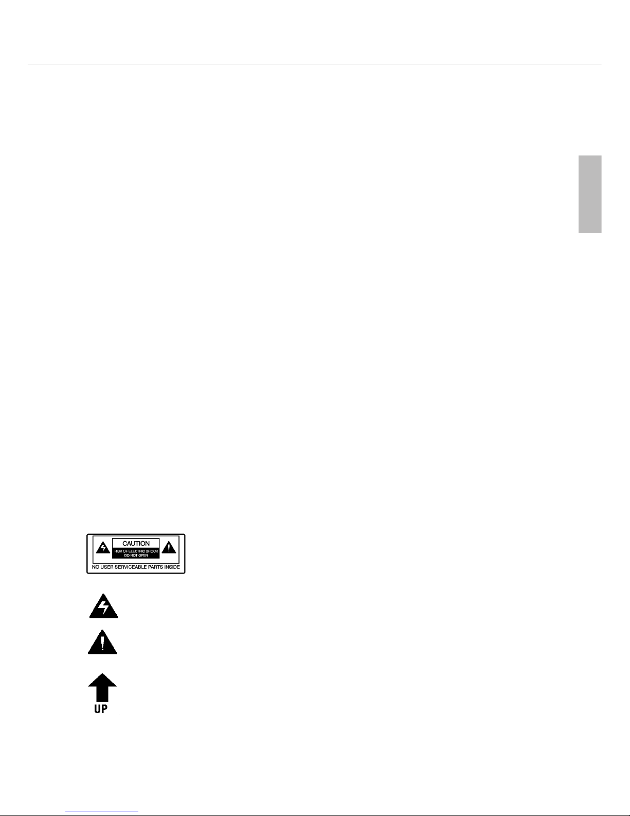
The label shown on the left is attached to back of the unit. The symbols on this label
have the following meaning:
This symbol indicates that dangerous voltage constituting a risk of electric shock is present within this
unit.
This symbol indicates that there are important operating and maintenance instructions in the literature
accompanying this unit.
This symbol on the rear panel of the power supply indicates that the power supply must be mounted
in the direction shown by arrow such that its top is always on upper side.
Safety symbols
Page 6
MCS 20 – Power Supply Unit
38
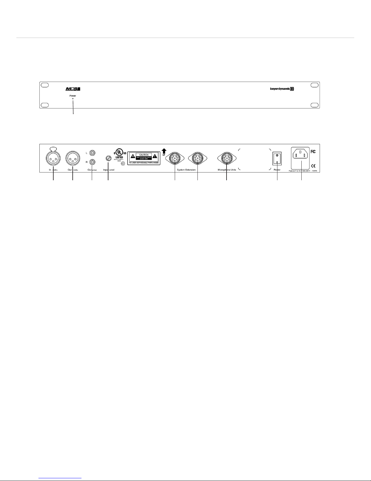
2.2 Controls and indicators
Power on LED
Audio input, 3-pin XLR, balanced, ungrounded, adjustable via “Input Level” potentiometer
Audio output, 3-pin XLR, balanced, ungrounded
Line output, e.g. for recorders
Input level control
Connection for more power supply units / system extension
Connection for microphone units
On/Off switch
Power connection with fuse holder
MCS 20 front view
MCS 20 rear view
2.3 Operation
Power connection
• Check whether the connection figures comply with the existing mains supply. Serious damage could occur due to
connecting the system to the wrong power supply.
• Make sure the power cable cannot be damaged or severed by sharp objects.
• Connect the MCS 20 power supply unit to the mains. Make sure the mains cable is firmly connected to the
MCS 20 power connection . The fuse holder contains a 3.15 AT fuse.
Renk sockets
• The MCS 20 power supply unit provides Renk sockets to connect further MCS 20 power supply units and
microphone units . Further microphone units can be connected to the individual power supply units. Refer also
to chapter 4. “Examples of a system configuration”.
Note: Please make sure that the microphone units are connected to the appropriate connection only.
• Also please ensure that pin no. 8 of the Renk sockets is always grounded while in use, so that pin no. 3 of the
Renk socket has +24 V with reference to ground and pin no. 7 of the Renk socket has -24 V with reference to
ground.
Audio connections
• Audio input , 3-pin XLR socket, input, balanced, ungrounded; can be adjusted with the “Input Level” potentiometer.
The input signal is routed to the loudspeakers of the microphone unit and released via the audio output.
Connection:
1 = System ground (No connection to the protective earthing conductor to avoid hum!)
2 = +Signal
3 = -Signal
Page 7

MCS 20 – Power Supply Unit
39
english
• Audio output , 3-pin XLR connector, +6 dB output, balanced, ungrounded, master output of all microphones
and the signal of the audio input for recordings and audio transmission.
Connection:
1 = NC - not connected
2 = +Signal
3 = -Signal
• Line output , RCA socket, line output; master output of all microphones and audio input.
Turning on/off
• Check all connections before turning on the power supply unit. A mains voltage between 100 and 240 V is
suitable, because a change over to another voltage is not necessary. Turn on the MCS 20 systems with the power
switch .
• The green LED on the front indicates the operating status.
Important notes for power supply units
• If several power supply units are used in one system, they should be simultaneously turned on, e.g. with a
common power switch.
• To avoid an overload of the cables never connect two or more power supply units with T-adapters!
• Several MCS 20 units can be stockpiled in a rack. For a sufficient ventilation leave a space of one height unit (U) over
and under the unit. The space behind the devices must not be closed.
Important:
When you install the MCS 20 power supply unit into a rack, please make sure that the rack has been earthed
(connected to the earth wire of the electrical installation).
For rack mounting use screws of a minimum size of M 6 x 15 mm.
• The ambient temperature should not exceed 40 °C. The devices have been designed for an operation in dry
rooms only!
2.4 Cabling
• The number of the required power supply systems for one system depends upon the number of microphones
turned on simultaneously. This can probably increase the number of required power supply units. The maximum
number of simultaneously turned on delegate microphone units (max. 8) has to be considered. If the configuration
switches 1, 2 or 3 of the microphone units are switched to “OFF”, the number of microphone units to be turned
on simultaneously is increased over the limit (max. 8) and consequently the load of the power supply units.
• Connect the conference socket of the first microphone unit to the connection for microphone units of the
MCS 20 power supply unit.
• Connect the conference socket of the first microphone unit to the conference socket of the second micro-
phone unit and so on, until all microphone units are connected.
• If you use self-assembled cables, observe the cable specifications from beyerdynamic and check each cable for
short circuits, interruptions and wrong connections.
Warning: beyerdynamic assumes no liability or warranty for damages caused by cables which are not
manufactured by beyerdynamic.
• Individual cable branches must not exceed a length of 160 metres each.
Maximum cable length within one system: 1000 metres.
• The minimum supply of the last microphone unit in a chain must be ±18 V.
• When using MCS 221 microphone units up to 60 microphone units can be connected to one MCS 20 power
supply unit with a maximum cable length of 2.5 metres between each microphone unit. When using the
MCS 263 up to 45 under-table microphone units can be connected to one MCS 20 power supply unit.
Note: Please contact beyerdynamic if you plan to use larger systems or complex cable topologies.
• In larger systems distribute the microphone units evenly to the power supply units. For example if want to connect
70 microphone units to two power supply units, connect 35 microphone units to the first power supply unit and
35 microphone units to the second power supply unit.
Page 8
MCS 20 – MCS 221 Microphone Unit
40
3. Microphone units
3.1 Safety information
General
• The microphone units provide a gooseneck microphone. Take care that you do not injure yourself on this e.g. poke it
into your eye.
• To align the gooseneck microphone on the microphone station and to avoid twisting it too far and causing
premature wear, always grip the microphone by the bottom flexible section never by the microphone head or by
the rigid tube. The gooseneck must be bent no further than an angle of 90 ° maximum.
Volume
• If the participants of the meeting use a headphone with the microphone units, please make sure that the volume
is not set too high. Otherwise the hearing of the participants could permanently be damaged.
• When the volume is set too high, acoustic feedback (howling) can occur.
Connection
• Make sure that the connector is tightly connected to the microphone unit. If it is loose it can cause interferences.
Exemption from liability
• beyerdynamic GmbH & Co. KG will not be liable if any damage, injury or accident occurs due to negligent,
incorrect or inappropriate operation of the product.
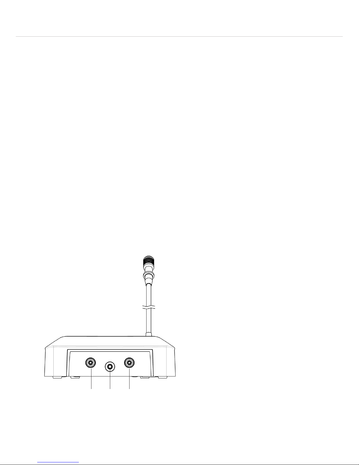
3.2 MCS 221 delegate microphone unit – controls and indicators
Rear view
Conference socket to connect to the next microphone unit or to the power supply unit
Headphone connection, mini jack (3.5 mm)
Conference socket to connect to the next microphone unit or to the power supply unit
Page 9
MCS 20 – MCS 221 Microphone Unit
41
english
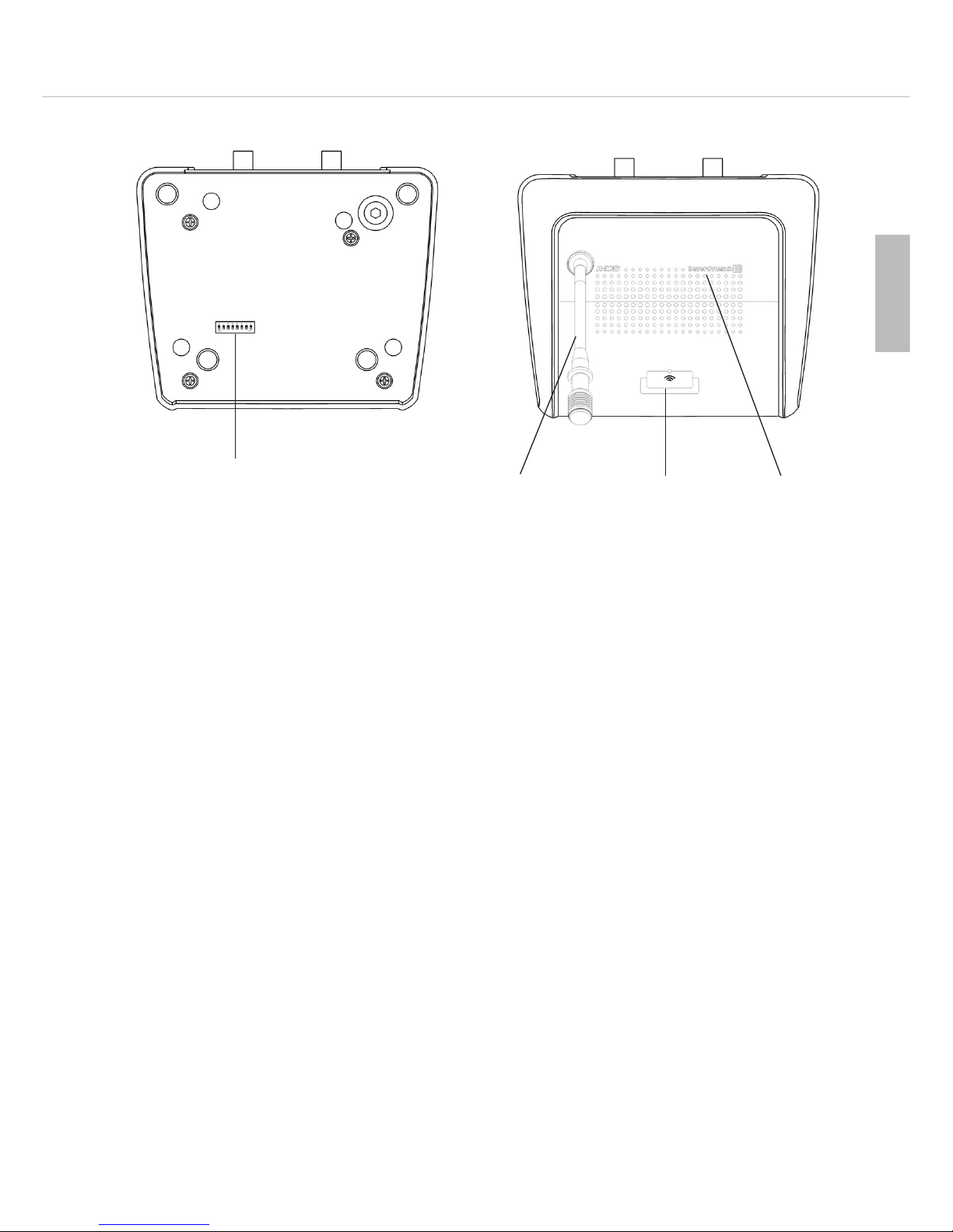
Bottom view
Top view
Configuration switches (DIP switches)
Gooseneck microphone with LED ring
Microphone button with LED
Loudspeaker
3.2.1 How to operate the MCS 221 delegate microphone unit
• For speaking, the microphone of the MCS 221 delegate microphone unit has to be activated. When the micro-
phone is activated, the LED ring of the gooseneck microphone and the LED of the microphone button will
illuminate. In the “Free” operating mode each delegate can turn on his microphone with the microphone button .
In the “Request” operating mode, the delegate has to press the microphone button to enter a request-to-speak. In
the “Request” mode the LED ring of the microphone unit will flash, before the chairman can activate the microphone of the delegate microphone unit with the “Req” button. In the “FiFo”mode a microphone unit is turned
off, when another one is turned on. A distance of approx. 30 cm between the speaker and microphone is close
enough.
• When the delegate speaks into his activated microphone, the signal is transmitted via all loudspeakers to the other
microphone units. The loudspeaker of the current speaker is automatically deactivated. Each microphone unit features a
limiter of 40 dB to avoid overrides when talking closely.
Important: If a headphone is connected to the microphone unit, it will be muted when the microphone is activated.
• The microphone of the delegate microphone unit can be turned on voice-controlled, which allows an operation
without pressing the microphone button when the speaker speaks into the microphone.
The “Voice Activation” operating mode can also be selected with the chairman microphone unit.
• The delegate microphone units are turned off, when the delegate presses his microphone button or when the
chairman presses the “Clear” button.
This is also effected with the “Req” button in the “Request” mode, when the next speaker may speak.
In the “Voice” operation the microphone is automatically turned off after a pause of two seconds.
• The admitted talk time for the current speaker can be determined and displayed with the “Timer” function.
Depending on the setting the activated microphone unit can automatically be turned off after an audio warning
for instance or the exceeded talk time is displayed. In addition to standard functions, many settings can be allocated
and changed via configuration switches and programming. This provides a varity of operating modes and operation.
Page 10
MCS 20 – MCS 221 Microphone Unit
42
3.2.2 Configuration switch
• At the bottom of the delegate microphone units there are configuration switches. Depending on the “ON” or
“OFF” position, the functions listed in the table below are allocated. For programming functions of the MCS 223
chairman microphone unit, please refer to chapter 3.3.8 “Programming mode” and 3.3.9 “Table of programmable
functions”.
ON OFF
1* Microphone unit is counted to the limit Microphone unit is not counted to the limit
2* Microphone unit is counted to the limit in the
“VOICE” operation
Microphone unit is not counted to the limit in the
“VOICE” operation
3* Limit refers to microphone unit Limit does not refer to microphone unit
4* “VOICE” operation allowed “VOICE” operation not allowed
5* Microphone unit cannot be cleared; can be turned
on in all operating modes - observe switch 3
Microphone unit can be cleared
6 without function without function
7 without function without function
8 Microphone button enabled in “VOICE” operation Microphone button disabled in “VOICE” operation
*When this switch is set to “OFF”, the maximum number of simultaneously open delegate microphone units is more
than 8. This results is an increased power consumption.
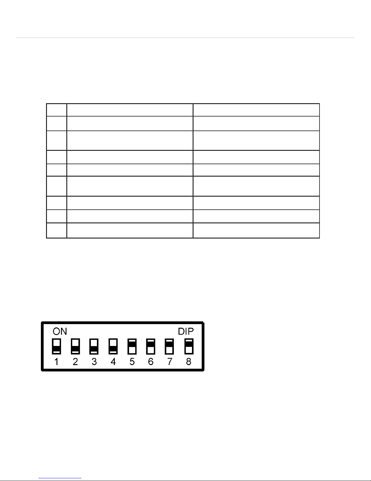
Example of the configuration switches of a MCS 221 delegate microphone unit, which has been configured
to a “sub-chairman”.
1 OFF – Microphone unit is not counted to the limit
Switch 1 of this microphone unit is set to “OFF”: the microphone of this microphone unit and three other
MCS 221 microphone units (= 4 microphone units) are activated. The limit of the MCS 223 chairman microphone unit is set to 4. Another speaker can turn on his microphone even though, because the microphone
unit, whose switch is set to “OFF”, is not counted to the limit.
This function for example can be selected for a microphone unit to make announcements. This microphone
unit should not block the activation of the delegate microphone units.
Page 11

MCS 20 – MCS 221 Microphone Unit
43
english
2 OFF – Microphone unit is not counted to the limit in the “VOICE” operation
This switch refers only to the MCS 221 delegate microphone unit.
3 OFF – Limit does not refer to this microphone unit
The speaker can also turn on his microphone unit or enter a request-to-speak, when the limit is already
achieved.
4 OFF – VOICE operation not allowed
When this switch is set to “OFF”, the voice-controlled activation is not possible (whether this operation
mode has been selected by the chairman). It can be activated with the microphone button, when switch 8
or 5 is set to “ON”.
5 ON – Microphone unit cannot be cleared - can be turned on in all operating modes - observe switch 3
The microphone unit can be turned on in all operating modes, but not when the limit is already achieved.
As switch 3 is set to “OFF” in this example, the speaker can turn on his microphone unit when the limit is
achieved.
6 – without function
7 – without function
8 ON – Microphone button active in the voice-controlled operation mode
When switch 8 is set to “ON”, this microphone unit can be activated via the microphone button in the
voice-controlled operation mode.
When the switches 8 and 5 are set to “OFF”, the microphone unit can only be activated voice-controlled.
Note: When switch 5 is set to “ON”, the function of switch 8 is also activated. This microphone unit can also be
activated with the microphone button in the voice-controlled mode when switch 8 is set to “OFF”.
Page 12

MCS 20 – MCS 223 Microphone Unit
44
3.3 MCS 223 chairman microphone unit - controls and indicators
Rear view
Top view
Conference socket to connect to the next microphone unit or to the power supply unit
Headphone connection, mini jack (3.5 mm)
Conference socket to connect to the next microphone unit or to the power supply unit
Gooseneck microphone with LED ring
Microphone button with LED
Loudspeaker
“Priority” button
“Clear” button
“Limit” buttons [-] and [+]
Display to indicate limit and timer
Volume buttons [-] and [+]
“Voice” button with LED
“Free” button with LED
“Requ” button with LED
3.3.1 How to operate the MCS 223 chairman microphone unit
• If you connect more than 40 microphone units in a chain, you should connect the chairman microphone unit as
first microphone unit to the power supply unit.
• Press the microphone button to activate the microphone when you want to speak. When you are finished
with speaking, press the microphone button once again. When the microphone is activated, the LED ring of the
gooseneck and the LED of the microphone button will illuminate. A distance of approx. 30 cm between
speaker and microphone is close enough.
• In the “Voice Activation” operating mode, you need not press the microphone button. You just speak into the
microphone. When you are finished with speaking, the microphone is automatically switched off after approx.
2 seconds.
• To control the meeting, the chairman microphone unit provides control and additional functions, which are explained
in the following chapters:
– “Free”, “Requ”, “Voice” button, “FiFo” (button combinaton “Free” + “Requ”) to set the operation mode
– “Prior” button (priority button) for a short interruption e.g. for an announcement
– “Clear” button to turn off all delegate microphone units simultaneously
Page 13

MCS 20 – MCS 223 Microphone Unit
45
english
– “Limit” buttons to set the allowed number of activated or registered microphone units
– Volume buttons to set the system volume for all microphone units
– Activate / deactivate timer mode (button combination “Prior” + “Clear”)
– Programming mode (button combination “Voice” + “Requ”)
The programming mode of the chairman microphone unit and the configuration switches of the delegate
microphone units allow a customised operation of the system in addition to the standard settings.
3.3.2 Operating modes
• The MCS 223 chairman microphone unit allows to select various operating modes. They refer to all connected
microphone units. In the three operating modes “Request”, “Free” and “Voice” the number of activated microphone units can be limited.
• The limit is selected with the [-] and [+] limit buttons . The selected limit is shown in the display .
• The MCS 223 chairman microphone unit can always be turned on regardless of the operating mode and the
selected limit.
• In the “FiFo” operating mode the limit is limited to 1.
• In the “Free” and “Request” operating modes the timer function can be activated in addition to the speech time
limit.
• The speech time limit does not refer to the chairman microphone unit.
Free
• Each delegate can turn on his microphone, if the limit is not exceeded.
• Press the “Free” button to activate this operating mode. The appropriate LED will illuminate.
Requ (Request-to-speak)
• In this operating mode the delegates cannot turn on their microphones. They have to press the microphone
button to enter a request-to-speak. The request-to-speak is indicated by the flashing LED ring and LED of the
microphone button of the chairman microphone unit. Furthermore, the LED ring of the appropriate delegate microphone unit is flashing.
• Press the “Requ” button to activate this operating mode. The appropriate LED will illuminate.
• In the “Request” operating mode you release the next speaker by pressing the “Requ” button .
• If the limit has been set to two or higher, all speakers who entered a request-to-speak are simultaneously released by
pressing the “Requ” button . If only one speaker is to speak at a time, the limit in the “Request” mode must be
set to 1 (standard setting).
Voice (voice-controlled)
• Each delegate can simply speak into his microphone, if the limit is not exceeded.
• Press the “Voice” button to activate this operating mode. The appropriate LED will illuminate.
Threshold of the microphones in the voice-controlled mode
• Hold down the “Voice” button to select the microphone sensitivity of the MCS 221 and MCS 223 microphone
unit. When the LED is flashing, select the value for the threshold by pressing one of the volume buttons ([+] to
increase or [-] to reduce the sensitivity). The value can be between 1 (insensitive) and 84, and will be displayed
as long as the “Voice” LED is flashing.
• The standard setting is between 45 and 50.
• Deviating from the general “Voice” threshold, it is possible to select another one for the chairman microphone unit.
• The setting of the activation threshold is automatically stored and is loaded again, when the power supply unit is
turned on.
• The value of the activation threshold should be selected on site, as the distance between the microphone units and
the room acoustics affect the activation of the microphones.
Press the “Requ” button briefly.
The LED goes out and on again.
Hold down the “Requ” button until the LED will
flash.
The activated microphone unit is turned off, the
registered microphone unit is released.
The activated microphone unit is NOT turned off, the
registered microphone unit is released.
Page 14

MCS 20 – MCS 223 Microphone Unit
46
FiFo (first in - first out)
• The “FiFo” operating mode is selected with the button combination “Free” and “Requ” . Both LEDs of the
“Free” + “Requ” buttons will illuminate.
• When another microphone unit is activated, the microphone unit of the current speaker is deactivated. The limit in this
operating mode is 01.
• In the standard setting this function also refers to the chairman microphone unit. If the chairman microphone unit
is to be excluded partly or completely from this function, the values of this function have to be set to 00 in the
programming mode (refer to chapter 3.3.8 “Programming mode”). In the standard setting both functions are set
to 01.
For function 14 - Value 00 applies: MCS 223 does not turn off other microphone units.
For function 15 - Value 00 applies: MCS 223 is not turned off by other microphone units.
• The chairman is also allowed to speak in this operating mode at any time by holding down the “Prior” button.
3.3.3 Priority function (Prior)
• By holding down the “Prior” button the chairman is allowed to speak at any time.
• If the microphone was not activated, it will be turned on as long as the button is held down. All activated micro-
phones are temporarily muted (their LED rings are flashing) and turned on again, when the “Prior” button is
released.
• The button can be programmed as a “latching” button (press the button briefly for speaking and afterwards press
the button again) or “Auto-OFF” (after a pause of approx. 2 seconds the microphone is automatically turned off).
Furthermore, the “Prior” button can be linked with the microphone button to activate the priority function also
with the microphone button .
3.3.4 Clear function
• Press the “Clear” button to clear all activated delegate microphone units. Some delegate microphone units can
be configured so that they cannot be cleared.
• The “Clear” button can be held down for a while to avoid activations of microphones.
• This function can be reprogrammed.
3.3.5 How to adjust the limit
• With the “Limit” buttons you can determine the number of speakers, who are allowed to speak simultaneously
(“Free” and “Voice” mode) or who may enter a request-to-speak (“Request” mode). This option can be used for
all three operating modes.
• The chairman microphone unit can be turned on at any time independing of the operating mode and the selected
limits.
• In the “FiFo” operating mode (“Free” + “Requ”) the limit is set to 01.
• The limit refers to the activated operating mode, which is displayed by the illuminated LED in the “Mode” field.
Press the “Clear” button briefly.
(Display is briefly cleared to confirm)
Hold button down, until two dashes (- -) are
displayed.
All activated microphone units are cleared.
Registered microphone units are not cleared.
All activated and registered microphone units are
cleared.
Page 15

MCS 20 – MCS 223 Microphone Unit
47
english
• Select the operating mode, for which the limit is to be set. The selected operating mode is displayed by the
illuminated LED.
• Set the limit by pressing the [+] or [-] button, until the desired number is displayed .
• The buttons provide an auto-repeat function; i.e. the setting is automatically stored and loaded when the system
is turned on again.
• The maximum selectable limit value is 08. The value can be reduced by programming. With a limit of 00 only the
chairman can speak!
• In the “Request” operating mode you can release the next delegate microphone unit by pressing the “Requ”
button . If the selected limit is 02 or higher, you will activate all registered delegate microphone units
simultaneously. If only one delegate is to speak at a time, the limit must be 01 in the “Request” operating mode
(standard setting).
3.3.6 How to adjust the volume
• Press the [+] or [-] volume button to adjust the volume level of all microphone units. When the button is
pressed for the first time, the current volume is displayed and not yet changed.
• The buttons provide an auto-repeat function.
• The change is in 1 dB steps from 01 - 32.
• The volume can also be changed during the meeting.
• The setting is automatically stored and loaded when the system is turned on again.
• The maximum selectable volume can be reduced by programming. Furthermore, the volume buttons can be
disabled.
3.3.7 How to set the timer
• With the timer function a speech time limit can be set for the MCS 221 delegate microphone units in the operating
modes “Request” and “Free”.
• Depending on the setting (refer to chapter 3.3.9 “Programming functions table”) the following functions are
possible:
– Setting the speech time.
– Turning off the microphone unit after the speech time has elapsed with or without acoustic warning signal.
– Display the exceeded speech time without turning off the microphone unit after the speech time has elapsed
with or without acoustic warning signal.
• The setting is automatically stored and loaded when the system is turned on again.
• The timer applies to the activated operating mode which is displayed by an illuminated LED in the “Mode” field.
Whenever a microphone is activated, the timer is started with the set speech time and counts backwards.
• The speech time is shown in the display of the chairman microphone unit. If the remaining time is at least one
minute, the minutes are displayed. Two full stops are flashing in the display. If the remaining time is less than one
minute, the seconds are displayed. When the seconds are displayed only one full stop is flashing.
• When the warning time is achieved, an acoustic warning signal is heard over the loudspeakers. When the timer
has achieved 00, the microphone is turned off, a registered microphone is turned on or the exceeded speech time
is displayed, depending on the setting.
• When the chairman holds down the “Prior” button , the timer is stopped.
Limit value Operating mode
00 - 08 “Voice”, “Free”, “Request”
00 - 01 “FiFo” (button combination: “Free” + “Requ”
00 - 01 “Free” with timer (button combination: “Prior” + “Clear”)
“Request” with timer (button combination: “Prior” + “Clear”)
Page 16

MCS 20 – MCS 223 Microphone Unit
48
• Step 1 – Set limit to 01
The limit for the selected operating mode (“Free” or “Request”) should be set to 01. With a limit of >1 the
displayed speech time of the microphone unit turned on first applies to all microphone units turned on within the
limit. Consequently, these microphone units will also be turned off, when the first microphone unit is turned off.
• Step 2 – Settings
The settings can be programmed and differ from the standard settings. Refer to chapter 3.3.8 “Programming
mode”. The settings of the timer codes no. 16 - 21 are stored when the system is turned off and are not reset
when the standard values are accessed.
Note: If the speech time 00 is selected (no. 20 and 21 to 00) and no. 17 or no. 19 are set to 0, the elapsed
speech time is displayed starting with 0 when the microphone is turned on (timer display counts forwards instead
of backwards).
• Step 3 – Activate timer function without clearing turned on microphones
Hold down the “Prior” button and press the “Clear” button briefly. The timer function is displayed by two
full stops in the display .
OR
Activate timer function with clearing all turned on microphones
Hold down the “Clear” button and press the “Prior” button briefly. The function is displayed by two full
stops in the display .
No. Description Values Standard
(factory setting)
16 Warning signal in the “Free” mode before the speech
time has elapsed;
0 = no acoustic warning signal
0 ... 59 sec. 45
17 After the speech time has elapsed in the “Free” mode;
0 = Timer displays the exceeded speech time
1 = MCS 221 is turned off
0 or 1 0
18 Warning signal in the “Request” mode before the
speech time has elapsed;
0 = no warning signal
0 ... 59 sec. 45
19 After the speech has elapsed in the “Request” mode:
0 = Timer displays exceeded speech time (counts up)
1 = Timer stops (turned on MCS 221 must be released by
the chairman via the “Requ” button).
2 = Timer starts again (turned on MCS 221 is turned
off and registered MCS 221 is turned on)
0 ... 2 2
20 Speech time in minutes (applies to “Free” and
“Request” mode) no. 20 and 21 are added.
0 ... 99 min. 2
21 Speech time in seconds (applies to “Free” and
“Request” mode) no. 20 and 21 are added.
0 ... 59 sec. 30
Page 17

MCS 20 – MCS 223 Microphone Unit
49
english
• Step 4 – Leave timer function without clearing turned on microphones
Hold down the “Prior” button and press the “Clear” button briefly. The limit of the activated operating
mode is displayed .
OR
Leave the timer function with clearing turned on microphones
Hold down the “Clear” button and press the “Prior” button briefly. The limit of the activated operating
mode is displayed .
3.3.8 Programming mode
How to programme functions
• In addition to the settings for “Limit”, “Volume” and “Mode” the functions 1 - 21 of the programmed functions
table can be reprogrammed for the MCS 223 chairman unit.
• With this the operation of the MCS 223 chairman microphone unit can be adapted to the personal requirements of
the operator. For instance the function of changing the volume can be disabled or limited; it can be determined, if
the “Prior” button operates as a button or switch.
• The current function settings can be stored and loaded in 7 setups with the “Limit”, “Volume” and “Mode”
settings.
• The values 1 - 15 can be reset to standard values at any time by pressing the “Voice” + “Free” + “Requ”
buttons simultaneously.
• The values 16 - 21 are not reset by accessing the standard values.
• Step 1 – How to activate the programming mode
Press the “Voice” and “Requ” buttons simultaneously for a few seconds (press the “Voice” button first),
until the function number is displayed (refer to function table), which is indicated by a flashing full stop after
the left number.
• Step 2 – How to select the function
Press the limit buttons [+] or [-], until the requested function number is displayed .
• Step 3 – How to display the selected value
Press one of the “Vol” buttons briefly. The currently selected value of the chosen function is displayed (refer
to the table of programmed functions). This is indicated by a flashing full stop after the right number.
0.6
Full stop after the left
number is flashing
Function 06
0 1.
Currently selected
value: 01
Full stop after the right
number is flashing
Page 18

MCS 20 – MCS 223 Microphone Unit
50
• Step 4 – How to change the selected value
Press one of the “Vol” buttons , until the requested value is displayed .
• Step 5 – How to return to the function display
Press the [+] or [-] limit button to change from the displayed selected value (flashing full stop on the right) to
the function display (flashing full stop on the left).
Adjust further values of any functions by starting with step 3. When all settings are done, they can be filed under a
setup number of 1 - 7 by using the function 00.
When you leave the programming mode with step 6, all new settings remain automatically stored (also without
saving in a setup) to the next change or when loaded a stored setup - even without any operating voltage.
• Step 6 – How to leave the programming mode
If there is no entry after one minute, the programming mode is automatically left. Furthermore, you can leave the
mode as described in the following:
Press the “Clear” button .
OR
Press the “Voice” and “Requ” buttons simultaneously (press the “Voice” button first) to leave the
programming mode.
How to access standard values
• Press the buttons “Voice” + “Free” + “Requ” (all three buttons simultaneously - press the “Voice”
button first - and release). Then all current functions 1 - 15 are loaded with the standard values according to
the function table.
• This action does not change the values for the timer functions 16 - 21. The last settings remain stored.
How to save the configuration
• The current “Limit”, “Volume” and “Mode” settings remain automatically stored with the current values of the
functions 1 - 21 (refer to function table) until new values are set or stored setups are loaded - also without
operating voltage.
• With the function 00 all settings are stored under a setup number (1 - 7) to be loaded later. If the “Limit”,
“Volume” and “Mode” settings are not yet adjusted, you should do so now.
• Step 1 – How to activate the programming mode and adjust settings
Activate the programming mode and set the requested values. This can be done by loading a setup and
modifying the settings.
• Step 2 – How to select the function 00 (access setup menu)
Press the [-] “Limit” button until the function number 00 is displayed. The left full stop is flashing.
• Step 3 – How to select a setup number
Press one of the “Vol” buttons until the desired setup number (1 - 7) is displayed . The right full stop is
flashing.
• Step 4 – How to save a setup
Press the microphone button to save the setup under the selected setup number. Please make sure that the right
full stop is flashing in the display when saving. All displays are briefly turned off to confirm that the saving has
been successful.
• Step 5 – How to leave the programming mode
If there was no entry after one minute, the programming mode is automatically left. Furthermore, you can leave
the mode as described below:
Press the “Clear” button to leave the programming mode.
OR
Press the “Voice” and “Requ” buttons simultaneously (press the “Voice” button first) to leave the
programming mode.
Note: You should record the settings saved in the setups (e.g. in a copy of the table of programmable functions).
Page 19

MCS 20 – MCS 223 Microphone Unit
51
english
How to load the configuration
• The procedure for loading a setup is almost the same as when saving a setup. Please note in step 4 you have to
press the “Prior” button instead of the microphone button .
• Step 1 – How to activate the programming mode
Press the “Voice” button and the “Requ” button simultaneously for a few seconds (press the “Voice”
button first), until a function number is displayed (refer to the table of programmable functions), which is
indicated by a flashing full stop after the left number.
• Step 2 – How to select function 00 (setup menu)
Press the [-] “Limit” button , until the function number 00 is displayed.
• Step 3 – How to select the setup number
Press one of the “Vol” buttons , until the requested setup number (1 - 7) is displayed . The full stop after the
right number is flashing.
• Step 4 – How to load the setup
Press the “Prior” button to load the saved setup. Please make sure that the full stop after the right number in
the display is flashing. When the loading has been successful, the display is briefly turned off to confirm.
• Step 5 – How to leave the programming mode
If there is no entry after one minute, the programming mode is automatically left. Furthermore, you can leave the
programming mode as described below:
Press the “Clear” button .
OR
Press the “Voice” button and the “Requ” button simultaneously (press the “Voice” button first).
0.6
full stop after the left
number is flashing
function 06
Page 20

MCS 20 – MCS 223 Microphone Unit
52
3.3.9 Table of programmable functions
No. Description Value
range
Factory
setting
00 Save or load setups 1 ... 7 -
01 Max. volume 0 ... 32 32
02 Volume setting with the “Vol” buttons
1 = enabled
0 = disabled
0 or 1 1
03 Max. limit for “Voice” mode 0 ... 8 8
04 Max. limit for “Free” mode 0 ... 8 8
05 Max. limit for “Request” mode 0 ... 8 8
06 Separate “Voice” threshold for MCS 223 (applies, when function 07 is set to
1, otherwise the general “Voice” threshold applies. Refer also to function 08.)
1 ... 84 40
07 Separate “Voice” threshold for MCS 223 activated (refer to function 06)
0 = no separate
1 = separate
0 or 1 0
08 MCS 223 “Voice activation”
0 = only in the “Voice” mode
1 = in all operating modes
2 = never (when “2” is selected, the microphone is only activated via the
microphone button)
0 ... 2 0
09 no function (must be set to “0”) 0
10 MCS 223 “Priority” is linked with the microphone button:
0 = not linked
1 = linked (“Priority” function is also released via the microphone button)
0 or 1 0
11 MCS 223 “Priority” button:
0 = push button mode
1 = latching mode
2 = Auto-OFF (Auto-Off depends on the general or separate “Voice”
threshold; function 06)
0 ... 2 0
12 MCS 223 Microphone button:
0 = push button mode
1 = latching mode
2 = Auto-OFF (Auto-Off depends on the general or separate “Voice”
threshold; function 06)
0 ... 2 1
13 MCS 223 “Clear” button:
0 = short press: turn off activated microphone units;
long press: turn off activated and registered microphone units
1 = turn off activated and registered microphone units always; independing on
how long the button is pressed
0 or 1 0
Page 21

MCS 20 – MCS 223 Microphone Unit
53
english
No. Description Value
range
Factory
setting
14 “FiFo” = “Requ” + “Free”:
0 = MCS 223 does not turn off another microphone unit
1 = MCS 223 turns off another microphone unit
0 or 1 1
15 “FiFo” = “Requ” + “Free”:
0 = MCS 223 is not turned off by another microphone unit
1 = MCS 223 is turned off by another microphone unit
0 or 1 1
16 Warning signal in the “Free” mode before the speech time has elapsed;
0 = no warning signal
0 ... 59 sec. 45
17 After the speech time has elapsed in the “Free” mode
0 = Timer indicates the exceeded speech time (counts up)
1 = MCS 221 is turned off
0 or 1 0
18 Warning signal in the “Request” mode before the speech time has elapsed;
0 = no warning signal
0 ... 59 sec. 45
19 After the speech time has elapsed in the “Request” mode:
0 = Timer indicates the exceeded speech time (counts up)
1 = Timer stops (activated MCS 221 is turned off and the registered MCS 221
must be activated by the chairman with the “Requ” button)
2 = Timer starts again (activated MCS 221 is turned off and registered
MCS 221 is turned on)
0 ... 2 2
20 Speech time is displayed in minutes (applies to “Free” and “Request” mode
(no. 20 and 21 are added)
0 ... 99 min. 2
21 Speech time is displayed in seconds (applies to “Free” and “Request” mode
(no. 20 and 21 are added)
0 ... 59 sec. 30
Page 22

MCS 20 – MCS 263 System Unit
54
3.4 MCS 263 system unit
The MCS 263 system unit allows flexible and discreet installations. It provides a 5-pin XLR connector for microphones
and phantom power. A terminal strip allows connecting loudspeakers, up to three buttons such as microphone button,
priority button and clear button as well as an LED for microphone on (illuminating) and request-to-speak (flashing).
Another terminal strip allows to connect a headphone.
3.4.1 Connections
Terminal strip to connect microphone, clear and prior buttons as well as LED and loudspeaker
Conference socket to connect to the next microphone unit or to the power supply unit
Terminal strip to connect a headphone
Microphone connection, 5-pin XLR
3.4.2 MCS 263 configuration switch
• At the bottom of the MCS 263 system unit there are configurations switches. Depending on the “ON” or “OFF”
position, the functions listed in the table below are allocated.
Page 23

MCS 20 – MCS 263 System Unit
55
english
*When this switch is set to “OFF”, the maximum number of simultaneously open delegate microphone units is more
than 8. This results is an increased power consumption.
3.4.3 Installation
The MCS 263 system unit provides removable mounting clips for installations under the table or in armrests.
Installation under the table
• Provide appropriate holes for the button, microphone
and loudspeaker in the tabletop.
• Mount the system unit with the mounting clips and
appropriate (or supplied) screws to the tabletop.
• Connect the button to the “MIc” connection of the
terminal strip .
• Connect the gooseneck microphone to the 5-pin XLR
connection
.
ON OFF
1* Microphone unit is counted to the limit Microphone unit is not counted to the limit
2* Microphone unit is counted to the limit in the
“VOICE” operation
Microphone unit is not counted to the limit in the
“VOICE” operation
3* Limit refers to microphone unit Limit does not refer to microphone unit
4* “VOICE” operation allowed “VOICE” operation not allowed
5* Microphone unit cannot be cleared; can be turned
on in all operating modes - observe switch 3
Microphone unit can be cleared
6 Clear button activated, only when used as sub-
chairman
Clear button not activated
7 Prior button activated, only when used as sub-
chairman
Prior button not activated
8 Microphone button enabled in “VOICE” operation Microphone button disabled in “VOICE” operation
Page 24

MCS 20 – MCS 263 System Unit
56
Installation with MPR 211 microphone
• Provide an appropriate hole for the connection of the
MPR 211 in the tabletop.
• Mount the system unit with the mounting clips and
appropriate (or supplied) screws to the tabletop.
• Connect the connecting cable of the MPR 211 to the
5-pin XLR connection
.
• In this way the MPR 211 microphone becomes an
additional conference microphone unit.
• For the pin assignment please refer to the chapter
5. “Technical specifications”.
Installation into an armrest
• Provide appropriate holes for the button, microphone
and loudspeaker in the armrest.
• Mount the system unit with the mounting clips and
appropriate (or supplied) screws under the armrest.
• Connect the button to the “MIc” connection of the
terminal strip .
• Connect the gooseneck microphone to the 5-pin XLR
connection
.
Page 25

MCS 20 – MCS 263 System Unit
57
english
Top view with dimensions
Page 26

MCS 20 – MCS 263 System Unit
58
3.4.4 How to use the MCS 263 as a delegate microphone unit
• Connect a microphone button to the “Mic” connection of the terminal strip .
• Connect a microphone to the microphone connection .
• You can connect an external LED via the terminal strip with the markings “LED -” and “LED +”.
• If you use a loudspeaker you can connect it to the “Speaker -” and “Speaker +” connection of the terminal
strip .
• The microphone button is used to turn the microphone on or off.
• The ready-to-speak status of the microphone is indicated by a red LED of the microphone itself or by a possible
external LED.
• In the “Free” mode each delegate can turn on his microphone with the microphone button.
• In the “Request” mode of the discussion system the microphone button is used to enter a request-to-speak. The
possible external LED and the LED ring of the gooseneck microphone will flash to indicate the request-to-speak.
When the microphone is released by the operator of the chairman microphone unit, the LED changes from
flashing to permanent illumination. In order to delete the request-to-speak the delegate can press the microphone
button once again.
• In the “FiFo” mode a microphone unit is turned off, when another one is turned on. A distance of approx. 30 cm
between the speaker and microphone is close enough.
• When the delegate speaks into his activated microphone, the signal is transmitted via all loudspeakers to the
other microphone units. The loudspeaker of the current speaker is automatically deactivated. Each microphone
unit features a limiter of 40 dB to avoid overrides when talking closely.
Important: If a headphone is connected to the microphone unit, it will be muted when the microphone is
activated.
• The microphone of the delegate microphone unit can be turned on voice-controlled, which allows an operation
without pressing the microphone button when the speaker speaks into the microphone.
The “Voice Activation” operating mode can also be selected with the chairman microphone unit.
• The delegate microphone units are turned off, when the delegate presses his microphone button or when the
chairman presses the “Clear” button.
This is also effected with the “Req” button in the “Request” mode, when the next speaker may speak.
In the “Voice” operation the microphone is automatically turned off after a pause of two seconds.
• The allocated time for the current speaker can be determined and displayed with the “Timer” function.
Depending on the setting the activated microphone unit can automatically be turned off after an audio warning
for instance or the exceeded talk time is displayed. In addition to standard functions, many settings can be allocated
and changed via configuration switches and programming. This provides a varity of operating modes and operation.
Page 27

MCS 20 – MCS 263 System Unit
59
english
3.4.5 How to use the MCS 263 as a sub-chairman microphone unit
• If you would like to operate the MCS 263 as a chairman microphone unit you can enter a so-called sub-chairman
mode to make the functions “Prior” and “Clear” available.
• Connect a microphone button to the “Mic” connection of the terminal strip .
• Connect a microphone to the microphone connection .
• Connect a clear button to the “Clear” connection of the terminal strip .
• Connect a prior button to the “Prior” connection of the terminal strip .
• You can connect an external LED to the “LED -” and “LED +” connections of the terminal strip .
• If you would like to use a loudspeaker, connect a loudspeaker to the “Speaker -” and “Speaker +” connection of
the terminal strip .
• Configure the DIP switches at the bottom as described below:
Example (in chapter 3.4.2 you will find an explanation of the switches):
Important:
When operating the microphone unit as a sub-chairman, the switches 6 and 7 must be set to “On”.
• The microphone button is used to turn the microphone on or off.
• The ready to speak status of the microphone is indicated by a red LED of the microphone and by a possible
external LED.
• The “Prior” button is used for short interruptions, e.g. announcements. By holding down the “Prior” button, the
chairman can speak at any time. If the microphone was not activated, it will be turned on as long as the button is
held down. All activated microphones are temporarily muted (their LED rings are flashing) and turned on again,
when the “Prior” button is released.
• The “Clear” button is used to clear all activated delegate microphone unit. Some delegate microphone units can
be configured so that they cannot be cleared. Some delegate microphone units can be configured so that they
cannot be cleared. The “Clear” button can be held down for a while to avoid activations of microphones.
Important:
In order to control the conference system, a MCS 223 chairman microphone unit must be connected in addition to
the MCS 263.
Page 28

MCS 20 – System Configuration
60
4. Examples for a system configuration
MCS 221 MCS 221 MCS 223
MCS 20
MCS 221 MCS 221 MCS 221
MCS 20
MCS 223 MCS 221 MCS 221
MCS 20
MCS 221 MCS 221 MCS 221
MCS 20
Configuration with a MCS 20 power supply unit
Configuration with several MCS 20 power supply units
Note: A maximum of 60 microphone units can be connected to one power supply unit.
further MCS 221
further MCS 221
further MCS 221
further MCS 221
Note: Only one MCS 223 chairman microphone unit can be connected. The position of the MCS 223 can freely be
selected within the cable system..
Page 29

MCS 20 – System Configuration
61
english
MCS 221
T-adapter
MCS 221 MCS 223
MCS 221 MCS 221 MCS 221
MCS 20
Note: Only one MCS 223 chairman microphone unit can be connected.
Configuration with T-adapter
further MCS 221
further MCS 221
Note: When using MCS 221 microphone units up to 60 microphone units can be connected to one MCS 20 power
supply unit with a maximum cable length of 2.5 metres between each microphone unit. When using the MCS 263
up to 45 system units can be connected to one MCS 20 power supply unit.
MCS 223 MCS 263 MCS 263
MCS 20
Configuration with MCS 263
more MCS 263
Page 30

MCS 20 – Technical Specifications
62
5. Technical specifications
MCS 20 power supply unit
Frequency response. . . . . . . . . . . . . . . . . . . . . . . . . 50 - 20,000 Hz
Input power . . . . . . . . . . . . . . . . . . . . . . . . . . . . . . 250 VA
Output power . . . . . . . . . . . . . . . . . . . . . . . . . . . . . 150 W
Output current . . . . . . . . . . . . . . . . . . . . . . . . . . . . ± 3 A
Output voltage . . . . . . . . . . . . . . . . . . . . . . . . . . . . ± 24 V
Output level (XLR / RCA) . . . . . . . . . . . . . . . . . . . . . +6 dBu, bal.
Input level (XLR) . . . . . . . . . . . . . . . . . . . . . . . . . . . -10 - +6 dBu, bal.
Supply voltage . . . . . . . . . . . . . . . . . . . . . . . . . . . . 100 - 240 V AC 50/60 Hz
Fuse . . . . . . . . . . . . . . . . . . . . . . . . . . . . . . . . . . . . 3.15 AT
Temperature range . . . . . . . . . . . . . . . . . . . . . . . . . 0 °C to +40 °C (humidity 90%)
Dimensions (L x H x D). . . . . . . . . . . . . . . . . . . . . . . 483 x 44 x 165 mm
Weight . . . . . . . . . . . . . . . . . . . . . . . . . . . . . . . . . . 2700 g
MCS 221 / MCS 223 microphone units
Loudspeaker system . . . . . . . . . . . . . . . . . . . . . . . . wideband loudspeaker, voice-equalised
Temperature range . . . . . . . . . . . . . . . . . . . . . . . . . 0 °C to +40 °C (humidity 90%)
Dimensions (W x H x D). . . . . . . . . . . . . . . . . . . . . . 170 x 54 x 143 mm
Weight . . . . . . . . . . . . . . . . . . . . . . . . . . . . . . . . . . 1070 g (MCS 221) / 1080 g (MCS 223)
MCS 221 delegate microphone unit
Current consumption
turned on, with microphone . . . . . . . . . . . . . . . . . . 77 mA
reproduction without audio signal. . . . . . . . . . . . . . 36 mA
reproduction with audio signal . . . . . . . . . . . . . . . . approx. 50 mA
MCS 223 chairman microphone unit
Current consumption
turned on, with microphone . . . . . . . . . . . . . . . . . . 123 mA
reproduction without audio signal. . . . . . . . . . . . . . 81 mA
reproduction with audio signal . . . . . . . . . . . . . . . . approx. 95 mA
MCS 263 system unit
Current consumption
turned on, with microphone . . . . . . . . . . . . . . . . . . 94 mA
reproduction without audio signal. . . . . . . . . . . . . . 45 mA
reproduction with audio signal . . . . . . . . . . . . . . . . approx. 70 mA
Powering microphone . . . . . . . . . . . . . . . . . . . . . . . phantom powering 24 V DC
supply resistor 1.2 kΩ on the basis of IEC 61938 / DIN 45596
with a load of 440 Ω of the 24 V DC output . . . . . . approx. 125 mA
Pin assignment of 5-pin XLR microphone connection
MPR 211 Connection
1 = GND/Shield Shield
2 = Audio + white
3 = Audio - brown
4 = LED 5 = LED +
Page 31

MCS 20 – Accessories
63
english
Pin assignment of 11-pin terminal strip
1 = 24 V DC MPR 211 Connection
2 = Ground
3 = Microphone Mic Status blue
4 = Clear button
5 = Prior button
6 = Ground GND green
7 = LED + Logic Power red
8 = LED - Logic Input grey
9 = Loudspeaker +
10 = Loudspeaker 11 = Shield
Pin assignment of 3-pin terminal strip
1 = Headphone right
2 = Com
3 = Headphone left
6. Maintenance
• Only clean the microphone units with a slightly damp or dry cloth. Never use cleansing agents containing solvents
as these damage the surface. Make sure not to allow any water to enter the microphone head.
7. Accessories
7.1 Supplied accessories
MCS 20
• Power cable
• CA 1801 extension cable, 0.3 m long
• CA 1810 connecting cable, 10 m long
MCS 221
• CA 1802 cable, approx. 2.5 m long
MCS 223
• CA 1802 cable, approx. 2.5 m long
• Operating instructions
MCS 263
• CA 1802 cable, approx. 2.5 m long
7.2 Optional accessories
CA 1802 Connecting cable, 2.5 m long . . . . . . . . . . . . . . . . . . . . . . . . . . . . . . . . . . . . . . . . . . Order # 486.345
CA 1805 Connecting cable, 5 m long . . . . . . . . . . . . . . . . . . . . . . . . . . . . . . . . . . . . . . . . . . . . Order # 486.353
CA 1810 Connecting cable, 10 m long . . . . . . . . . . . . . . . . . . . . . . . . . . . . . . . . . . . . . . . . . . . Order # 486.361
CA 1820 Connecting cable, 20 m long . . . . . . . . . . . . . . . . . . . . . . . . . . . . . . . . . . . . . . . . . . . Order # 486.388
CA 1800 Connecting cable, sold by metre without connector. . . . . . . . . . . . . . . . . . . . . . . . . . Order # 486.396
Page 32

MCS 20 – Cable Specifications
64
8. Cable specifications for self-made cables
CA 1813 T-Adapter . . . . . . . . . . . . . . . . . . . . . . . . . . . . . . . . . . . . . . . . . . . . . . . . . . . . . . . . . . Order # 486.612
CA 1835 Connector 8-pin Renk . . . . . . . . . . . . . . . . . . . . . . . . . . . . . . . . . . . . . . . . . . . . . . . . Order # 486.639
CA 1841 Button for MCS 263, red LED ring, stainless steel . . . . . . . . . . . . . . . . . . . . . . . . . . . . Order # 722.529
Page 33

MCS 20 – Notes
65
english
Page 34

98
EC-DECLARATION
OF
CONFORMITY
Application of
Council directive: 2004/108/EC
Electromagnetic Compatibility
2006/95/EC
Low Voltage Directive
Standards to which
Conformity is declared: EN 61 000-6-1 Immunity
EN 61 000-6-3 Emission
EN 60 065 Safety
Manufacturer's Name: beyerdynamic GmbH & Co. KG
Manufacturer's Address: Theresienstrasse 8, 74072 Heilbronn, Germany
Type of Equipment: Conference & Discussion System
Model Numbers: MCS 20, MCS 221, MCS 223
I, the undersigned, as an employee of beyerdynamic, hereby declare that the equipment
specified conforms to the above Directive and Standards.
Manufacturer’s signature:
Full Name: Ulrich Roth
Date: 1
st
January 2008
Position: Director of R&D
Page 35

Page 36

DEF 5/BA MCS 20 (07.10)/620.203/Hoh. • Abbildungen nicht vertragsbindend. Änderungen und Irrtümer vorbehalten • Non-contractual illustrations. Subject to change without notice. •
Illustrations non contractuelles.
Sous réserve de modifications. • Printed in Germany.
beyerdynamic GmbH & Co. KG
Theresienstr. 8 | 74072 Heilbronn – Germany
Tel. +49 (0) 7131 / 617 - 0 | Fax +49 (0) 7131 / 617 - 204
info@beyerdynamic.de | www.beyerdynamic.com
Weitere Vertriebspartner weltweit finden Sie unter www.beyerdynamic.com
For further distributors worldwide, please go to www.beyerdynamic.com
 Loading...