

Page 1

PRODUKTINFORMATION
PRODUCT INFORMATION
INFORMATIONS DE PRODUIT
MCE 72
MCE 72 CAM
MCE 72 PV CAM
Kondensatormikrofon
Condenser Microphone
Microphone à condensateur
Page 2

3
Notes importantes. . . . . . . . . . . . . . . . . . . . . . . . . . . . . . Page 16
Application . . . . . . . . . . . . . . . . . . . . . . . . . . . . . . . . . . . Page 16
Mise en service . . . . . . . . . . . . . . . . . . . . . . . . . . . . . . . . Page 16
Insérer la pile. . . . . . . . . . . . . . . . . . . . . . . . . . . . . . . . . . Page 17
Branchement. . . . . . . . . . . . . . . . . . . . . . . . . . . . . . . . . . Page 17
Montage et orientation . . . . . . . . . . . . . . . . . . . . . . . . . . Page 18
Entretien . . . . . . . . . . . . . . . . . . . . . . . . . . . . . . . . . . . . . Page 18
Service après-vente . . . . . . . . . . . . . . . . . . . . . . . . . . . . . Page 18
Modèles . . . . . . . . . . . . . . . . . . . . . . . . . . . . . . . . . . . . . Page 19
Accessoires en option . . . . . . . . . . . . . . . . . . . . . . . . . . . Page 19
Spécifications techniques . . . . . . . . . . . . . . . . . . . . . . . . Page 20
Courbe de fréquence & diagramme
de directivité, diagramme de câblage . . . . . . . . . . . . . . . Page 22
Evacuation . . . . . . . . . . . . . . . . . . . . . . . . . . . . . . . . . . . Page 25
INHALT / CONTENTS / SOMMAIRE
PRODUKTINFORMATION MCE 72
deutsch
Wichtige Hinweise . . . . . . . . . . . . . . . . . . . . . . . . . . . . . Seite 4
Anwendung . . . . . . . . . . . . . . . . . . . . . . . . . . . . . . . . . . Seite 4
Inbetriebnahme. . . . . . . . . . . . . . . . . . . . . . . . . . . . . . . . Seite 4
Batterie einlegen . . . . . . . . . . . . . . . . . . . . . . . . . . . . . . . Seite 5
Anschluss . . . . . . . . . . . . . . . . . . . . . . . . . . . . . . . . . . . . Seite 5
Aufstellung und Ausrichtung. . . . . . . . . . . . . . . . . . . . . . Seite 6
Pflege . . . . . . . . . . . . . . . . . . . . . . . . . . . . . . . . . . . . . . . Seite 6
Service . . . . . . . . . . . . . . . . . . . . . . . . . . . . . . . . . . . . . . Seite 7
Versionen . . . . . . . . . . . . . . . . . . . . . . . . . . . . . . . . . . . . Seite 7
Zubehör optional . . . . . . . . . . . . . . . . . . . . . . . . . . . . . . Seite 7
Technische Daten . . . . . . . . . . . . . . . . . . . . . . . . . . . . . . Seite 8
Frequenzkurve, Richtdiagramm, Schaltbild . . . . . . . . . . . Seite 22
Entsorgung . . . . . . . . . . . . . . . . . . . . . . . . . . . . . . . . . . . Seite 25
PRODUCT INFORMATION MCE 72
english
Important Notes . . . . . . . . . . . . . . . . . . . . . . . . . . . . . . . Page 10
Application . . . . . . . . . . . . . . . . . . . . . . . . . . . . . . . . . . . Page 10
Putting into Operation . . . . . . . . . . . . . . . . . . . . . . . . . . Page 10
How to insert the Battery . . . . . . . . . . . . . . . . . . . . . . . . Page 11
Connection . . . . . . . . . . . . . . . . . . . . . . . . . . . . . . . . . . . Page 11
Setting up . . . . . . . . . . . . . . . . . . . . . . . . . . . . . . . . . . . . Page 12
Maintenance. . . . . . . . . . . . . . . . . . . . . . . . . . . . . . . . . . Page 12
Service . . . . . . . . . . . . . . . . . . . . . . . . . . . . . . . . . . . . . . Page 12
Versions . . . . . . . . . . . . . . . . . . . . . . . . . . . . . . . . . . . . . Page 12
Optional Accessories . . . . . . . . . . . . . . . . . . . . . . . . . . . . Page 13
Technical Specifications. . . . . . . . . . . . . . . . . . . . . . . . . . Page 14
Frequency Response, Polar Pattern, Wiring Diagram . . . . . . Page 22
Disposal. . . . . . . . . . . . . . . . . . . . . . . . . . . . . . . . . . . . . . Page 25
INFORMATIONS DE PRODUIT MCE 72
français
Page 3

5
deutsch
4
PRODUKTINFORMATION MCE 72
Sie haben sich für das Stereomikrofon MCE 72 von
beyerdynamic entschieden. Vielen Dank für Ihr Vertrauen.
Nehmen Sie sich bitte einige Minuten Zeit und lesen Sie
diese Produktinfor mation vor Inbetriebnahme aufmerksam durch.
Wichtige Hinweise
• Schützen Sie das Mikrofon vor Feuchtigkeit,
Herunterfallen und Schlag. Sie könnten sich oder
andere verletzen bzw. das Mikrofon beschädigen.
• Pusten Sie nicht in das Mikrofon. Bei einem Kon den satormikrofon können Sie den Wandler be schä digen.
Geben Sie einer Sprechprobe den Vorzug.
• Achten Sie bei kabelgebundenen Mikrofonen stets
darauf, dass die Mikrofonkabel so verlegt werden,
dass niemand darüber stolpern und sich verletzen
kann.
Anwendung
Das MCE 72 wurde für XY-Stereoaufnahmen entwickelt.
Es kann beim Homerecording, für Konzertmitschnitte mit
DAT oder MD, Film- und Videoton sowie Interviews verwendet werden.
Das MCE 72 ist in drei Versionen erhältlich:
• MCE 72 ausschließlich für den Batteriebetrieb.
• MCE 72 CAM ausschließlich für den Batteriebe trieb.
Mit Zubehör für den Einsatz mit Kameras.
• MCE 72 PV CAM ausschließlich für den Betrieb mit
Phantomspeisung. Mit Zubehör für den Einsatz mit
Kameras.
Inbetriebnahme
MCE 72 PV CAM
Das MCE 72 PV CAM kann nur mit Phantomspeisung
zwischen 11 und 52 V betrieben werden.
MCE 72 / MCE 72 CAM
Das MCE 72 und MCE 72 CAM kann nur mit eingelegter
Batterie betrieben werden. Ein Betrieb über Phan tom spei sung ist nicht möglich.
Mit dem Schalter kann das Mikrofon ein- und ausge schaltet sowie der Batteriezustand kontrolliert werden.
Position „OFF“: Batteriespeisung bzw. Mikrofon ist
ausgeschaltet.
Position „B.C.“: Batteriezustand wird kontrolliert.
Bei voller Batterie leuchtet die rote
LED über dem Schalter.
Leuchtet die LED nicht, ist entweder
keine Batterie eingelegt oder die
Batteriekapazität zu schwach und
die Batterie muss gewechselt werden.
ACHTUNG:
Betreiben Sie das Mikrofon nicht
in dieser Schalterstellung, da die
Batteriekapazität sonst schnell erschöpft wird.
Position „ON“: Batteriespeisung ist eingeschaltet
und das Mikrofon somit betriebsbereit.
Batterie einlegen
Schrauben Sie den unteren Teil des Mikrofons entgegen
dem Uhrzeigersinn ab und legen Sie die mitgelieferte
1,5 V Alkalinebatterie polungsrichtig in das Batterie fach
ein.
Schrauben Sie den unteren Teil des Mikrofons im
Uhrzeigersinn wieder auf.
Wichtig:
• Wenn Sie das Mikrofon längere Zeit nicht benu tzen, sollten Sie die Batterie immer herausneh men, um ein
Entladen (Stand-by Strom) bzw. Aus laufen der Batterie
und dadurch Schäden am Mikrofon zu vermeiden.
Auch die Bezeichnung „Leak proof“ ist keine Garantie
gegen Auslaufen. In diesem Fall entfallen alle
Garantieansprüche.
• Werfen Sie leere Batterien nicht in den Hausmüll,
sondern geben Sie diese an den örtlichen Sammel stellen ab.
Anschluss
Die Mikrofone MCE 72 und MCE 72 CAM sind mit einem
5-pol. XLR-Stecker ausgestattet. Für den Anschluss an
Geräte mit 3,5 mm Stereoklinken eingang muss das mit-
Page 4
Service
Im Servicefall wenden Sie sich bitte an autorisiertes
Fachpersonal. Öffnen Sie das Mikrofon auf keinen Fall
selbst, Sie könnten sonst alle Garantiean sprüche verlieren.
Versionen
Bez. Beschreibung . . . . . . . . . . . . Best.-Nr.
MCE 72 PV CAM
Stereo-Kondensatormikrofon,
Niere, für Phantomspeisung,
mit elastischer Aufhängung
EA 86 für Montage auf Kamerablitzschuh, Windschutz WS 72
und Kabel MVK 82-N(CM)
0,5 m . . . . . . . . . . . . . . . . . . . 492.612
MCE 72 CAM Stereo-Kondensatormikrofon,
Niere, mit elastischer Aufhängung
EA 86 für Montage auf Kamerablitzschuh, Windschutz WS 72
und Kabel MVK 72-K3 . . . . . . 470.635
MCE 72 dito, jedoch mit Mikrofon-
klammer MKV 108 und
Kabel MVK 82-K3 . . . . . . . . . . 465.461
Zubehör optional
MVK 72-K3 Mikrofonanschlusskabel mit
5-pol. XLR-Buchse und
Stereoklinkenstecker 3,5 mm,
0,35 m lang . . . . . . . . . . . . . . 470.643
MVK 82-K3 Mikrofonanschlusskabel mit
5-pol. XLR-Buchse und
Stereoklinkenstecker 3,5 mm,
2,5 m lang . . . . . . . . . . . . . . . 450.949
MVK 82-N(CM)
Mikrofonanschlusskabel mit
5-pol. XLR-Buchse und
2 x 3-pol. XLR-Stecker,
2,5 m lang . . . . . . . . . . . . . . . 448.966
MVK 82-N(CM)
dito, jedoch 0,5 m lang . . . . . 481.777
EA 19/25 Elastische Aufhängung,
mit Mikrofonklammer
MKV 11 . . . . . . . . . . . . . . . . . 407.194
7
deutsch
6
gelie ferte Kabel (5-pol. XLR/ 3,5 mm Stereoklinke) an das
jeweilige Mikrofon ange schlossen werden. Die Mikro fone
können dann an alle gängigen Cam corder sowie DAT- und
MD-Recorder direkt ange schlossen werden. Eine
eventuell am Eingang des Re corders anliegende
Speisespannung (Plug-in Power) beeinträchtigt die
Funktion des Mikrofons nicht.
Das MCE 72 PV CAM ist ebenfalls mit einem 5-pol. XLR-
Stecker ausgestattet. Zum Anschluss muss das Kabel
MVK 82 N(CM) verwendet werden.
Die Mikrofone können mit elastischen Aufhän gungen
eingesetzt werden.
Mit der EA 19/25 wird tieffrequenter Trittschall unterdrückt. Mit der EA 86 mit Blitzschuhhalter kann das
MCE 72 direkt auf den Blitzschuh eines Camcorders
montiert werden, wobei die Übertragung von
Kopftrommel- und Laufwerksvibrationen verhindert
wird.
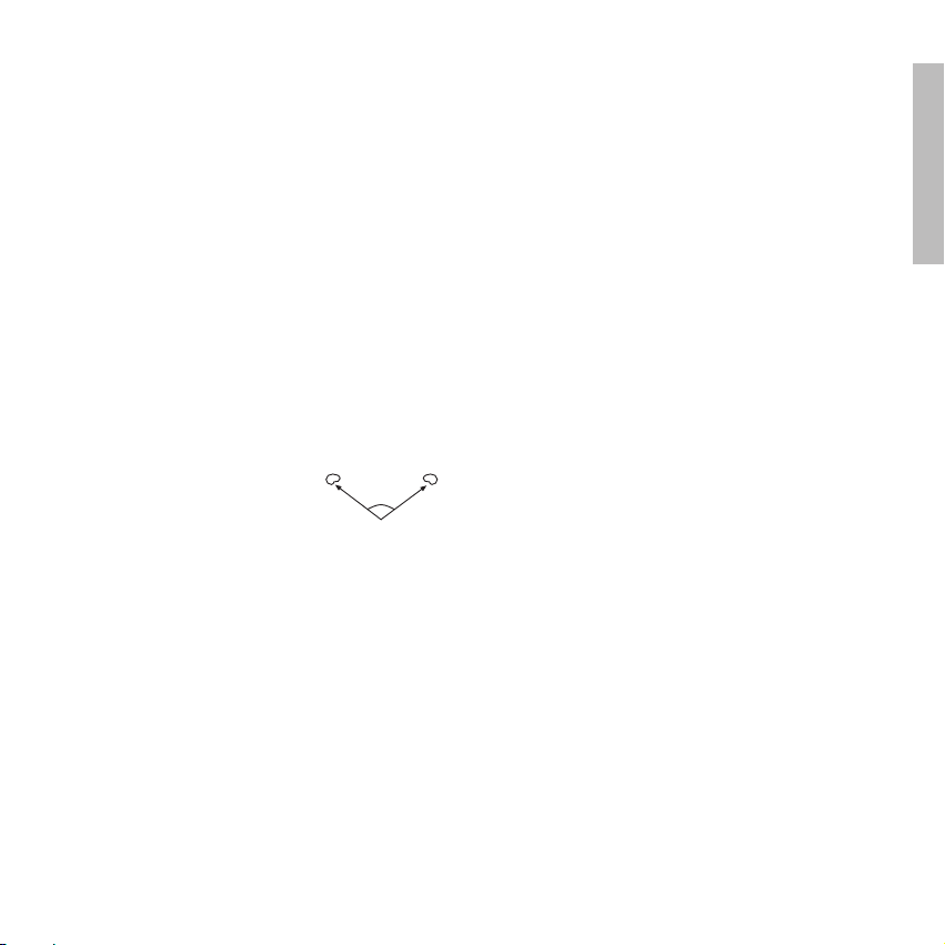
Aufstellung und Ausrichtung
Richten Sie das Mikrofon auf die
Schallquelle so aus, dass die
Beschriftung nach oben zeigt. „L“
zeigt dabei zur linken Seite und
„R“ zur rechten.
Der Hauptachsenwinkel der beiden Mikrofon kap seln
beträgt 120°. Hierdurch ergibt sich ein Auf nahme winkel
von 140°, d.h. ±70° zur Mikrofon achse. Schallquellen
innerhalb dieses Aufnahme winkels werden je nach
Position von ganz links bis ganz rechts aufgenommen.
Die Breite der Stereo basis lässt sich über den
Aufnahmeabstand variieren: ein kleiner Abstand bewirkt
eine breite Abbildung und umgekehrt.
Pflege
Bei Bedarf reinigen Sie das Mikrofon mit einem weichen
feuchten Tuch. Wenn notwendig, können Sie ein mildes
Reinigungsmittel (z.B. Ge schirr spülmittel) verwenden,
auf keinen Fall löse mittelhaltige Reiniger. Achten Sie
darauf, dass in das Mikrofon kein Wasser läuft.
120∞
LR
Page 5

9
deutsch
8
Bez. Beschreibung . . . . . . . . . . . . Best.-Nr.
EA 86 Elastische Aufhängung mit
Blitzgeräteschuh BS 86 . . . . . . 407.186
MAV 800 Clip 3/8", zum
Abhängen von
Mikrofonen. . . . . . . . . . . . . . . 448.133
MKV 8 Mikrofonklammer, mit
3/8"-Innen gewinde,
für Schaft 22 - 32 mm . . . . . . 407.216
WS 72 Windschutz,
Farbe: anthrazit. . . . . . . . . . . . 565.016
WS 101 Windschutz,
Farbe: anthrazit. . . . . . . . . . . . 111.244
WJ 930 Windjammer (zusätzlicher
Fellwindschutz für WS 72),
40 mm Haarlänge . . . . . . . . . . 490.903
Technische Daten
Wandlerprinzip . . . . . . . . . . . . . Kondensator
(Back-Elektret)
Arbeitsprinzip . . . . . . . . . . . . . . Druckgradien ten-
empfänger
Übertragungsbereich . . . . . . . . . 60 - 20.000 Hz
Aufnahmeverfahren. . . . . . . . . . XY-Stereophonie
Richtcharakteristik . . . . . . . . . . . 2 x Niere, Haupt -
achsen winkel 120°
Feldleerlaufübertragungsfaktor bei 1 kHz
MCE 72 / MCE 72 CAM . . . . . . 12 mV/Pa
MCE 72 PV CAM . . . . . . . . . . . . 26 mV/Pa
Nennimpedanz . . . . . . . . . . . . . 180 Ω
Nennabschlussimpedanz . . . . . . > 1 kΩ
Max. Grenzschalldruckpegel
bei 1 kHz
MCE 72 / MCE 72 CAM . . . . . . 120 dB
MCE 72 PV CAM . . . . . . . . . . . . 120 dB
Geräuschspannungsabstand
bez. auf 1 Pa . . . . . . . . . . . . . . . ca. 60 dB
A-bewerteter Äquivalent-
schalldruckpegel . . . . . . . . . . . . ca. 26 dB
Spannungsversorgung
MCE 72 / MCE 72 CAM . . . . . . 1,5 V Batterie
(Mignon AA)
MCE 72 PV CAM . . . . . . . . . . . . Phantomspeisung
11 - 52 V
Stromaufnahme
MCE 72 / MCE 72 CAM . . . . . . 12 mA
MCE 72 PV CAM . . . . . . . . . . . . 3,7 mA pro Kanal
Betriebsdauer mit einer
Batterie LR 6 (2300 mAh)
MCE 72 / MCE 72 CAM . . . . . . ca. 75 Std.
Ausgang
MCE 72 / MCE 72 CAM . . . . . . unsymmetrisch,
kapazitiv entkoppelt
MCE 72 PV CAM . . . . . . . . . . . . symmetrisch
Anschluss
MCE 72 / MCE 72 CAM . . . . . . 5-pol. XLR male
Pin 1 = Schirm
Pin 2 = NF - links
Pin 3 = frei
Pin 4 = NF - rechts
Pin 5 = frei
MCE 72 PV CAM . . . . . . . . . . . . 5-pol. XLR male
Pin 1 = Schirm
Pin 2 = NF + links
Pin 3 = NF - links
Pin 4 = NF + rechts
Pin 5 = NF - rechts
Anschlusskabel
MCE 72 / MCE 72 CAM
Eingang . . . . . . . . . . . . . . . . . . . 5-pol. XLR female
Ausgang . . . . . . . . . . . . . . . . . . 3,5 mm Stereo-
klinkenstecker
MCE 72 PV CAM
Eingang . . . . . . . . . . . . . . . . . . . 5-pol. XLR female
Ausgang . . . . . . . . . . . . . . . . . . 2 x 3-pol. XLR male
Kabellänge. . . . . . . . . . . . . . . . . 0,5 m
Abmessungen
MCE 72 / MCE 72 CAM
Länge / Durchmesser . . . . . . . . . 196 mm / 25 mm
MCE 72 PV CAM
Länge / Durchmesser . . . . . . . . . 136 mm / 25 mm
Gewicht (ohne Batterie)
MCE 72 / MCE 72 CAM . . . . . . 175 g
MCE 72 PV CAM . . . . . . . . . . . . 135 g
Page 6

11
english
10
PRODUCT INFORMATION MCE 72
Thank you for selecting the MCE 72 stereo condenser
microphone. Please take some time to read carefully
through this product information before using the product.
Important Notes
• Protect the microphone from moisture and sudden
impacts. You could either injure yourself or others or
damage the microphone.
• Do not blow into the microphone. In a condenser
microphone this could damage the transformer. It is
preferable to carry out a speech trial.
• When using wired microphones always ensure that
the microphone cable is laid so that it does not present
a trip hazard.
Application
The MCE 72 has been developed for XY recording. It is
suitable for stereo recording in home studio applications,
concert recordings with DAT or MD, film, video and interviewing.
The MCE 72 is available in three versions:
• The MCE 72 is battery powered.
• The MCE 72 CAM is battery powered and supplied
with accessories for camera use.
• The MCE 72 PV CAM is phantom powered and
supplied with accessories for camera use.
Putting into Operation
MCE 72 PV CAM
The MCE 72 PV CAM can only be used with a phantom
power between 11 and 52 V.
MCE 72 / MCE 72 CAM
The MCE 72 and MCE 72 CAM can be used batterypowered only. Phantom power is not possible.
Using the switch the microphone can be switched on and
off and the battery status can be checked.
Position “OFF”: Battery power or microphone is
switched off.
Position “B.C.” Battery condition is checked. The
red LED is illuminated when the
battery has full capacity.
If the LED does not illuminate,
there is no battery inserted or the
battery capacity is too weak and
the battery has to be replaced.
CAUTION:
Do not operate the microphone in
this position, as the battery will
rapidly become exhausted.
Position “ON”: Battery power is switched on; the
microphone is ready for operation.
How to insert the Battery
Unscrew the lower part of the microphone anti-clockwise
and insert the supplied alkaline battery (1.5 V) into the
battery compartment according to the polarity marks.
Screw the lower part of the microphone clockwise onto
the upper part.
Important:
• If you do not use the microphone for several weeks or
months, please remove the battery as it can discharge
(due to stand-by current) or leak after some time and
damage parts of the microphone. Even “leak proof”
may leak after some time. Damage caused by leaking
batteries is not covered under warranty.
• Please do not throw used battery packs away with
your household rubbish, but take them to your local
collection points.
Connection
The MCE 72 and MCE 72 CAM provide a 5-pin XLR plug.
Use the supplied cable (5-pin XLR/3.5 mm stereo jack) to
connect the microphone to devices with 3.5 mm stereo jack
socket. The microphones are suitable for direct connection to
most camcorders, DAT and MD recorders. If the input of
the recorder has a plug-in power, the function of the
MCE 72 is not affected.
The MCE 72 PV CAM also provides a 5-pin XLR plug. The
MVK 82 N(CM) cable must be used to connect the microphone.
Page 7

13
english
12
The microphones can be used with elastic suspensions.
The EA 19/25 elastic suspension suppresses footfall
sound effectively.
Using the special EA 86 elastic suspension with a flash
holder, the MCE 72 can be mounted onto the “hot shoe”
of a camcorder directly but remains isolated from noise
caused by the video head and the drive.
Setting up
Set up the microphone so that the
description points to the top. “L”
points to the left and “R” to the
right side.
The angle of the principal axis of the
two microphone capsules is 120°. This results in a pickup
angle of 140°, i.e. ±70° to the microphone axis.
Depending on their position sound sources within this
pickup angle are recorded from the very left to the very
right. The width of the stereo base can be adjusted via
the recording distance i.e. a small distance results in a
broad field and vice versa.
Maintenance
Use a soft, damp cloth for cleaning the microphone. If
necessary, you can use a gentle cleansing agent (such as
washing-up liquid). Make sure not to allow any water to
enter the transducer element and never use any solvent
cleansers.
Service
Servicing must be carried out by qualified service personnel
only. Dismantling the microphone yourself may invalidate
the guarantee.
Versions
Model Description . . . . . . . . . . . . . . Order #
MCE 72 PV CAM
Stereo condenser microphone,
cardioid, phantom powered,
with EA 86 elastic suspension
for mounting onto a “hot shoe”,
WS 72 wind shield and
MVK 82-N(CM) cable,
0.5 m . . . . . . . . . . . . . . . . . . . 492.612
Model Description . . . . . . . . . . . . . . Order #
MCE 72 CAM Stereo condenser microphone,
cardioid, with EA 86 elastic
suspension for mounting onto a
“hot shoe”, WS 72 wind shield
and MVK 72-K3 cable. . . . . . . 470.635
MCE 72 same as above,
but with MKV 108
microphone clamp
and MVK 82-K3 cable. . . . . . . 465.461
Optional Accessories
MVK 72-K3 Connecting cable with
5-pin XLR socket and
3.5 mm stereo jack plug,
0.35 m long . . . . . . . . . . . . . . 470.643
MVK 82-K3 Connecting cable with
5-pin XLR socket and
3.5 mm stereo jack plug,
2.5 m long . . . . . . . . . . . . . . . 450.949
MVK 82-N(CM)
Connecting cable with
5-pin XLR socket and
2 x 3-pin XLR plugs,
2.5 m long . . . . . . . . . . . . . . . 448.966
MVK 82-N(CM)
same as above,
but 0.5 m long . . . . . . . . . . . . 481.777
EA 19/25 Elastic suspension, with
MKV 11 mic clamp . . . . . . . . . 407.194
EA 86 Elastic suspension with
BS 86 set for flash holder . . . . 407.186
MAV 800 Clip 3/8" for hanging
installations of microphones
(from the ceiling) . . . . . . . . . . 448.133
MKV 8 Microphone clamp with
3/8" internal thread,
for shaft diameters
of 22 - 32 mm . . . . . . . . . . . . 407.216
WS 72 Wind shield, charcoal-grey . . . 565.016
WS 101 Wind shield, charcoal-grey . . . 111.244
WJ 930 Windjammer (additional
wind shield for MCE 72),
hair length 40 mm . . . . . . . . . 490.903
120∞
LR
Page 8

15
english
14
Technical Specifications
Transducer type . . . . . . . . . . . . . Condenser
(back electret)
Operating principle . . . . . . . . . . Pressure gradient
Frequency response . . . . . . . . . . 60 - 20,000 Hz
Recording . . . . . . . . . . . . . . . . . XY stereophony
Polar pattern . . . . . . . . . . . . . . . 2 x cardioid, principal
axis angle 120°
Open ciruit voltage at 1 kHz
MCE 72 / MCE 72 CAM . . . . . . 12 mV/Pa
MCE 72 PV CAM . . . . . . . . . . . . 26 mV/Pa
Nominal impedance. . . . . . . . . . 180 Ω
Load impedance . . . . . . . . . . . . > 1 kΩ
Max. SPL at 1 kHz
MCE 72 / MCE 72 CAM . . . . . . 120 dB
MCE 72 PV CAM . . . . . . . . . . . . 120 dB
Signal-to-noise ratio
rel. to 1 Pa. . . . . . . . . . . . . . . . . approx. 60 dB
A-weighted equivalent SPL . . . . approx. 26 dB
Power supply
MCE 72 / MCE 72 CAM . . . . . . 1.5 V battery
(Mignon AA)
MCE 72 PV CAM . . . . . . . . . . . . Phantom power
11 - 52 V
Current consumption
MCE 72 / MCE 72 CAM . . . . . . 12 mA
MCE 72 PV CAM . . . . . . . . . . . . 3.7 mA per channel
Operating time with battery
type LR 6 (2300 mAh)
MCE 72 / MCE 72 CAM . . . . . . approx. 75 hrs.
Output
MCE 72 / MCE 72 CAM . . . . . . unbalanced,
capacitor decoupled
MCE 72 PV CAM . . . . . . . . . . . . balanced
Connection
MCE 72 / MCE 72 CAM . . . . . . 5-pin XLR male
Pin 1 = Shield
Pin 2 = AF - left
Pin 3 = not connected
Pin 4 = AF - right
Pin 5 = not connected
MCE 72 PV CAM . . . . . . . . . . . . 5-pin XLR male
Pin 1 = Shield
Pin 2 = AF + left
Pin 3 = AF - left
Pin 4 = AF + right
Pin 5 = AF - right
Connecting cable
MCE 72 / MCE 72 CAM
Input . . . . . . . . . . . . . . . . . . . . . 5-pin XLR female
Output. . . . . . . . . . . . . . . . . . . . 3.5 mm Stereo jack
plug
MCE 72 PV CAM
Input . . . . . . . . . . . . . . . . . . . . . 5-pin XLR female
Output. . . . . . . . . . . . . . . . . . . . 2 x 3-pin XLR male
Cable length . . . . . . . . . . . . . . . 0.5 m
Dimensions
MCE 72 / MCE 72 CAM
Length / Diameter . . . . . . . . . . . 196 mm / 25 mm
MCE 72 PV CAM
Length / Diameter . . . . . . . . . . . 136 mm / 25 mm
Weight (without battery)
MCE 72 / MCE 72 CAM . . . . . . 175 g
MCE 72 PV CAM . . . . . . . . . . . . 135 g
Page 9

17
français
16
INFORMATIONS PRODUIT MCE 72
Nous vous félicitons pour l’achat du microphone stéréophonique MC 72 de beyerdynamic et vous remercions de
votre confiance. Veuillez lire attentivement ces informations
produit avant la mise en service du microphone.
Notes importantes
• Veillez à ce que le microphone soit protégé de l’humidité
et de tous dommages résultant de chutes ou de chocs
mécaniques.
• Ne soufflez pas dans le microphone. Dans le cas d’un
microphone à condensateur, vous pourriez endommager
le transformateur. Effectuez plutôt un test de parole.
• Pour les microphones à câble, veillez à poser les câbles de
sorte à ce que nul ne puisse trébucher dessus et se blesser.
Application
Le MCE 72 est un microphone conçu spécialement pour
les enregistrements en stéréo X/Y. Vous pouvez par exemple
l’utiliser pour les applications de «homerecording», les
enregistrements de concert avec DAT ou MD, la prise de
son cinéma/vidéo ainsi que des interviews.
MCE 72 est disponible en trois versions :
• MCE 72 uniquement pour fonctionnement avec pile.
• MCE 72 CAM uniquement pour fonctionnement avec
pile. Avec accessoires pour l’utilisation avec appareils
photo.
• MCE 72 PV CAM uniquement pour fonctionne ment
avec tension fantôme. Avec accessoires pour l’utilisation
avec appareils photo.
Mise en service
MCE 72 PV CAM
MCE 72 PV CAM peut uniquement fonctionner avec
tension fantôme entre 11 et 52 V.
MCE 72 / MCE 72 CAM
Le MCE 72 / MCE 72 CAM ne peut être opéré que si la
pile est insérée. Il est impossible d’opérer le microphone
par l’intermédiaire de la tension fantôme.
Utilisez le commutateur pour mettre le microphone
en/hors service et/ou contrôler l’état de la pile.
Position «OFF»: Alimentation par pile ou micro-
phone est hors service.
Position «B.C.»: Contrôle de l’état de la pile. Si la
pile est pleine, la DEL rouge audessus du commutateur s’allume.
Si la DEL ne s’allume pas, vous n’avez
pas insérer une pile ou la capacité de
la pile insérée est trop basse.
Remplacez la pile.
ATTENTION:
Ne jamais opérer le microphone
avec le commutateur mis à cette
position; sinon, vous risqueriez
d’épuiser la capacité de la pile.
Position «ON»: La tension de pile est en service, le
microphone fonctionne.
Insérer la pile
Dévissez la partie inférieure du microphone en sens inverse
des aiguilles d’une montre et insérez la pile alcaline 1,5 V
fournie avec le microphone dans le compartiment de pile
en respectant la polarité.
Revissez la partie inférieure du microphone en sens des
aiguilles d’une montre.
Important:
• Si vous n’utilisez pas le microphone pendant plusieurs
semaines ou mois, enlevez la pile afin d’éviter qu’elle
soit déchargée ou perde son étanchéité après une longue
période de non-utilisation, ce qui pourrait endommager
le microphone. Même l’indication «Leak proof» ne
constitue pas une garantie contres des fuites.
• Ne jetez pas les piles usées dans les ordures ménagères,
mais remettez-les à la déchetterie la plus proche prévue
à cet effet.
Branchement
Le MCE 72 et MCE 72 CAM sont munis d’une prise XLR 5
broches. Il convient de raccorder le câble fourni (5 broches,
XLR/3,5 mm jack stéréo) au microphone pour le branchement d’appareils dotés d'une entrée jack stéréo 3,5 mm.
Les microphones peuvent être raccordés directement à
tous les caméscopes courants, les lecteurs DAT et MD.
Une tension d’alimentation éventuellement appliquée à
Page 10

19
français
18
l’entrée du lecteur (plug-in-power) n’entrave pas la fonction
du microphone.
Le MCE 72 PV CAM est également doté d’une fiche XLR
5 broches. Le câble MVK 82 N(CM) doit être utilisé pour le
raccordement.
Les microphones peuvent être utilisés en option avec des
suspensions élastiques.
Les bruits basse fréquence sont supprimés avec
EA 19/25. Le MCE 72 peut être monté directement sur le
sabot flash d’un caméscope avec EA 86 équipé d’un
support de sabot flash; la transmission de vibrations
lecteur et autres étant évitées.
Montage et orientation
Orientez le microphone vers la source
sonore de façon à ce que l'inscription soit dirigée vers le haut. «L»
indique le côté gauche et «R» le
côté droit.
L'angle axial des deux capsules de microphone est de
120°. Il en résulte un angle d'enregistrement de 140°,
c.à.d. ± 70° à l'axe du microphone. Des sources sonores
comprises dans cet angle d'enregistrement sont enregistrées de gauche à droite selon la position. Il est possible
de varier la plage de la base stéréo via l'intervalle d’enregistrement: un petit intervalle donne une large reproduction
et vice-versa.
Entretien
Si besoin, nettoyez le microphone avec chiffon doux
humide et éventuellement un produit de nettoyage doux
(produit vaisselle, par ex.). N’employez jamais de produits
contentant des solvants. Veillez à ce que de l’eau ne
pénètre pas dans le microphone.
Service après-vente
En cas de nécessité veuillez vous adresser à un
technicien beyerdynamic autorisé. N’ouvrez jamais le
microphone, vous risquerez sinon de perdre vous droits
de garantie.
Modèles
Mod. Description . . . . . . . . . . . . . . Art. N°
MCE 72 PV CAM
Microphone condensateur
stéréo, cardioïde, pour
alimentation fantôme, avec
suspension élastique EA 86
pour montage sur un sabot
flash de caméra, bonnette
anti-vent WS 72 et
câble MVK 82-N(CM)
0,5 m . . . . . . . . . . . . . . . . . . . 492.612
MCE 72 CAM Microphone condensateur
stéréo, cardioïde, avec
suspension élastique EA 86
pour montage sur un sabot
flash de caméra, bonnette
anti-vent MCE 72 et
câble MVK 72-K3 . . . . . . . . . . 470.635
MCE 72 idem, mais avec pince de
microphone MKV 108 et
câble MVK 82-K3 . . . . . . . . . . 465.461
Accessoires en option
MVK 72-K3 Câble de connexion microphone
avec prise XLR à 5 broches et
fiche jack stéréo 3,5 mm;
longueur: 0,35 m . . . . . . . . . . 470.643
MVK 82-K3 Câble de connexion microphone
avec prise XLR à 5 broches et
fiche jack stéréo 3,5 mm;
longueur: 2,5 m . . . . . . . . . . . 450.949
MVK 82-N(CM)
Câble de connexion microphone
avec prise XLR à 5 broches et
2 fiches XLR à 3 broches;
longueur: 2,5 m . . . . . . . . . . . 448.966
MVK 82-N(CM)
idem, mais longueur 0,5 m. . . 481.777
EA 19/25 Suspension élastique, avec
pince de microphone
MKV 11 . . . . . . . . . . . . . . . . . 407.194
EA 86 Suspension élastique avec
sabot flash BS 86 . . . . . . . . . . 407.186
120∞
LR
Page 11

2120
Mod. Description . . . . . . . . . . . . . . Art. N°
MAV 800 Clip 3/8" pour la suspension
de microphones . . . . . . . . . . . 448.133
MKV 8 Pince de microphone,
avec filetage interne 3/8"
pour tige 22-32 mm . . . . . . . . 407.216
WS 72 Bonnette anti-vent;
couleur: anthracite . . . . . . . . . 565.016
WS 101 Bonnette anti-vent;
couleur: anthracite . . . . . . . . . 111.244
WJ 930 Housse de protection
pour WS 72 . . . . . . . . . . . . . . 490.903
Spécifications techniques
Type de transducteur . . . . . . . . . Condensateur
(back-électret)
Principe de
fonctionnement. . . . . . . . . . . . . gradient à pression
Bande passante . . . . . . . . . . . . . 60 - 20.000 Hz
Technique
d’enregistrement . . . . . . . . . . . . Stéréophonie X/Y
Directivité . . . . . . . . . . . . . . . . . 2 x cardioïde, angle
d’axe principale 120°
Efficacité en champs libre, 1 kHz
MCE 72 / MCE 72 CAM . . . . . . 12 mV/Pa
MCE 72 PV CAM . . . . . . . . . . . . 26 mV/Pa
Impédance nominale . . . . . . . . . 180 Ω
Impédance de charge . . . . . . . . > 1 kΩ
Pression sonore max, 1 kHz
MCE 72 / MCE 72 CAM . . . . . . 120 dB
MCE 72 PV CAM . . . . . . . . . . . . 120 dB
Rapport signal/ bruit, 1 Pa . . . . . 60 dB env.
Pression sonore
pondérée A . . . . . . . . . . . . . . . . 26 dB env.
Alimentation
MCE 72 / MCE 72 CAM . . . . . . Pile 1,5 V (Mignon AA)
MCE 72 PV CAM . . . . . . . . . . . . . . Fantôme 11 - 52 V
Consommation
MCE 72 / MCE 72 CAM . . . . . . 12 mA
MCE 72 PV CAM . . . . . . . . . . . . 3,7 mA par canal
Autonomie,
1 pile LR 6 (2300 mAh)
MCE 72 / MCE 72 CAM . . . . . . 75 heures env.
français
Sortie
MCE 72 / MCE 72 CAM . . . . . . asymétrique,
découplage capacitatif
MCE 72 PV CAM . . . . . . . . . . . . symétrique
Connecteur
MCE 72 / MCE 72 CAM . . . . . . XLR mâle à 5 broches
Broche 1 = blindage
Broche 2 = BF - gauche
Broche 3 = libre
Broche 4 = BF - droite
Broche 5 = libre
MCE 72 PV CAM . . . . . . . . . . . . XLR mâle à 5 broches
Broche 1 = blindage
Broche 2 = BF + gauche
Broche 3 = BF - gauche
Broche 4 = BF + droite
Broche 5 = BF - droite
Câble de connexion
MCE 72 / MCE 72 CAM
Entrée . . . . . . . . . . . . . . . . . . . . XLR femelle à
5 broches
Sortie. . . . . . . . . . . . . . . . . . . . . Fiche jack stéréo
3,5 mm
MCE 72 PV CAM
Entrée . . . . . . . . . . . . . . . . . . . . XLR femelle à
5 broches
Sortie. . . . . . . . . . . . . . . . . . . . . 2 x XLR mâle à
3 broches
Longueur du câble. . . . . . . . . . . 0,5 m
Dimensions
MCE 72 / MCE 72 CAM
Longueur / diamètre . . . . . . . . . 196 mm / 25 mm
MCE 72 PV CAM
Longueur / diamètre . . . . . . . . . 136 mm / 25 mm
Poids (sans pile)
MCE 72 / MCE 72 CAM . . . . . . 175 g
MCE 72 PV CAM . . . . . . . . . . . . 135 g
Page 12

2322
Frequenzkurve /
Frequency Response Curve /
Courbe de fréquence
Richtdiagramm / Polar Pattern /
Diagramme de directivité
Schaltbilder / Wiring Diagrams /
Diagrammes de câblage
MCE 72 / MCE 72 CAM
Page 13

2524
MCE 72 PV CAM
Entsorgung
Dieses Produkt darf am Ende seiner Lebensdauer nicht über den normalen Haushaltsabfall entsorgt werden, sondern muss an
einem Sammelpunkt für das Recycling von
elektrischen und elektronischen Geräten
abgegeben werden. Das Symbol auf dem
Produkt, der Gebrauchsanweisung oder der
Verpackung weist darauf hin.
Disposal
This symbol on the product, in the instructions
or on the packaging means that your electrical
and electronic equipment should be disposed
at the end of its life separately from your
household waste. There are separate collection
systems for recycling in the EU. For more
information, please contact the local authority
or your retailer where you purchased the
product.
Evacuation
Ce symbole sur le produit, l’emballage ou
dans le manuel signifie que votre équipement électrique et électronique doit être, en
fin de vie, jeté séparement de vos déchets
ménages. Il existe en France des systèmes de
collecte différents pour les déchets recyclables.
Pour plus d’information, veuillez contacter
les autorités locales ou le revendeur chez qui
vous avez acheté le produit.
Page 14

NOTIZEN • NOTES
Page 15

DEF4/PI MCE 72 / MCE 72 CAM / MCE 72 PV CAM (05.09)/589.829/Hoh. • Änderungen und Irrtümer vorbehalten • Subject to change without notice • Sous réserve de modifications • Printed in Germany
beyerdynamic GmbH & Co. KG
Theresienstr. 8 | 74072 Heilbronn – Germany
Tel. +49 (0) 7131 / 617 - 0 | Fax +49 (0) 7131 / 617 - 224
info@beyerdynamic.de | www.beyerdynamic.de
Weitere Vertriebspartner weltweit finden Sie unter www.beyerdynamic.de
For further distributors worldwide, please go to www.beyerdynamic.com
 Loading...