

Page 1

MA 206
4-Kanal-Mischverstärker
4-Channel-Mixing-System
MA 212
5-Kanal-Mischverstärker
5-Channel-Mixing-System
BEDIENUNGSANLEITUNG
OPERATING INSTRUCTIONS
Page 2

Page 3

3
INHALT / CONTENTS
BEDIENUNGSANLEITUNG MA 206 / MA 212
OPERATING INSTRUCTIONS MA 206 / MA 212
english deutsch
1. Ausführung . . . . . . . . . . . . . . . . . Seite 4 / 14
2. Sicherheitshinweise . . . . . . . . . . . Seite 4 / 14
3. Bedien- und Kontrollelemente . . Seite 6 / 16
4. Anschlüsse . . . . . . . . . . . . . . . . . . Seite 7 / 17
5. Inbetriebnahme. . . . . . . . . . . . . . Seite 8 / 19
6. Fehlercheckliste . . . . . . . . . . . . . . Seite 9 / 19
7. Zubehör - optional . . . . . . . . . . . Seite 10 / 20
8. Technische Daten. . . . . . . . . . . . . Seite 10 / 20
9. Ansicht Grundplatine . . . . . . . . . Seite 11 / 22
10. Schaltbild. . . . . . . . . . . . . . . . . . . Seite 12 / 23
1. Model . . . . . . . . . . . . . . . . . . . . . Page 24 / 34
2. Safety Information . . . . . . . . . . . Page 24 / 34
3. Controls and Indicators . . . . . . . . Page 26 / 36
4. Connection . . . . . . . . . . . . . . . . . Page 27 / 37
5. Setting up . . . . . . . . . . . . . . . . . . Page 28 / 39
6. Trouble Shooting. . . . . . . . . . . . . Page 29 / 39
7. Optional Accessories . . . . . . . . . . Page 30 / 40
8. Technical Specifications . . . . . . . . Page 30 / 40
9. Printed Circuit Board. . . . . . . . . . Page 31 / 42
10. Wiring Diagram. . . . . . . . . . . . . . Page 32 / 43
Page 4

4
BEDIENUNGSANLEITUNG 4-KANAL-MISCHVERSTÄRKER MA 206
Sie haben sich für den 4-Kanal-Mischverstärker MA 206 von beyerdynamic
entschieden. Vielen Dank für Ihr Vertrauen.
Nehmen Sie sich bitte einige Minuten Zeit und lesen Sie diese Bedienungsanleitung
vor Inbetriebnahme aufmerksam durch.
1. Ausführung
MA 206 4-Kanal-Mischverstärker . . . . . . . . . . . . . . . . . . Best.-Nr. 452.963
Der Mischverstärker MA 206 hat 2 Mikrofoneingänge, 1 Universaleingang (Mikrofon,
Auxiliary) und 1 Tonträgereingang mit einem gemeinsamen Summenpegelsteller
(Master) mit Klangregelnetzwerk (Höhen- und Tiefenentzerrung). Die Mikrofoneingänge 1 und 2 sind als Vorrangeingänge (sprachgesteuert) ausgelegt. Das laufende
Programm (Mikrofon und Tonträger) wird weich ausgeblendet.
2. Sicherheitshinweise
• LESEN Sie die Bedienungsanleitung/Produktinformation.
• BEWAHREN Sie diese Bedienungsanleitung/Produktinformation auf.
• BEFOLGEN Sie die aufgeführten Bedienungs- und Sicherheitshinweise.
• Das Gerät muss so aufgestellt werden, dass die Steckverbindung leicht zugänglich ist.
• Das Gerät muss an eine Netz-Steckdose mit Schutzkontakt angeschlossen werden.
• Setzen Sie das Gerät niemals Regen oder hoher Feuchtigkeit aus. Installieren Sie
es daher nicht in unmittelbarer Nähe von Swimming Pools, Duschanlagen,
feuchten Kellerräumen oder sonstigen Bereichen mit außergewöhnlich hoher
Luftfeuchtigkeit.
• Stellen Sie niemals mit Flüssigkeiten gefüllte Gegenstände (z.B. Vasen oder
Trinkgläser) auf das Gerät. Denn Flüssigkeiten in den Geräten können einen
Kurzschluss verursachen.
• Reinigen Sie das Gerät nur mit einem leicht feuchtem oder trockenem Tuch.
Verwenden Sie niemals Lösungsmittel, da diese die Oberfläche beschädigen.
• Installieren und betreiben Sie das Gerät auch niemals in unmittelbarer Nähe von
Heizkörpern, Beleuchtungsanlagen oder anderen wärmeerzeugenden Geräten.
• Verlegen Sie alle Kabel stets so, dass sie nicht durch scharfe Gegenstände
geknickt oder gar durchgetrennt werden können.
• Verlegen Sie alle Anschlusskabel so, dass niemand darüber stolpern und sich verletzen kann.
• Schalten Sie bei allen Arbeiten an den Ein- und Ausgängen die Stromzufuhr aus.
Page 5

deutsch
5
• Überprüfen Sie, ob die Anschlusswerte mit der vorhandenen Netzstromversorgung übereinstimmen. Bei Anschluss des Systems an die falsche Stromversorgung können ernsthafte Schäden entstehen. Eine falsche Netzspannung kann
das Gerät beschädigen oder einen elektrischen Schlag verursachen.
• Dieses Gerät benötigt eine ausreichende Ventilation. Decken Sie die Lüftungsöffnungen nicht ab. Wenn die Eigenwärme nicht abgeführt wird, kann das
Gerät beschädigt oder brennbare Materialien in unmittelbarer Nähe können
entzündet werden. Achten Sie daher darauf, dass die Luft durch die Lüftungsöffnungen frei zirkulieren kann und halten Sie brennbare Materialien fern.
• Wenn durch das Gerät ein Sicherungsdefekt oder ein Kurzschluss verursacht
wurde, nehmen Sie es vom Netz und lassen Sie es überprüfen und reparieren.
• Öffnen Sie nicht eigenmächtig das Gerät. Sie könnten einen elektrischen Schlag
erleiden. Überlassen Sie alle Servicearbeiten nur autorisiertem Fachpersonal.
• Berühren Sie den Kontaktstifte des Steckers nicht, nachdem Sie das Gerät vom
Netz getrennt haben, Sie könnten einen elektrischen Schlag erleiden.
• Stecken Sie keine Gegenstände in die Lüftungs- und andere Öffnungen. Sie
könnten das Gerät beschädigen und/oder sich verletzen.
• Setzen Sie das Gerät nicht ein, wenn der Netzstecker beschädigt ist.
Page 6
6
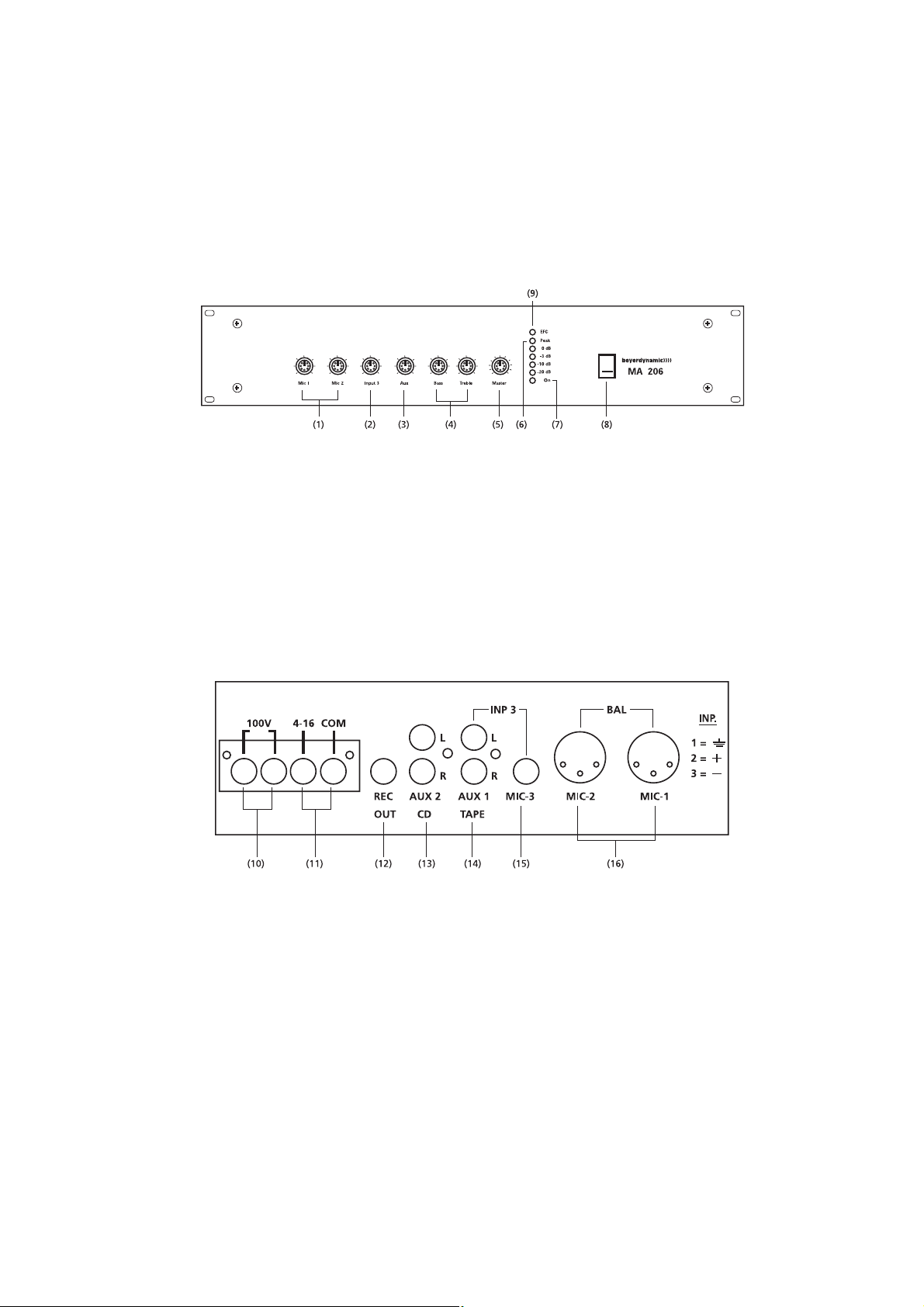
3. Bedien- und Kontrollelemente
Vorderseite
(1) Lautstärkeregler Mikrofoneingänge
(2) Lautstärkeregler Universaleingang
(3) Lautstärkeregler Tonträgereingang
(4) Klangregelung (Tiefen/Höhen)
(5) Lautstärkeregler Summe
(6) Pegelanzeige
(7) Betriebskontroll-LED
(8) Ein- und Ausschalter
(9) Anzeige für Erdschluß
Ausschnitt Rückseite
(10) 100 V Lautsprecherausgang
(11) Niederohmiger Lautsprecherausgang (4 - 16 Ω)
(12) Aufnahmeausgang
(13) Tonträgereingang
(14) Universaleingang für Tonträger
(15) Universaleingang für Mikrofon (unsymm.)
(16) Mikrofoneingänge
06060606 0600600
6
1
2
3
4
5
7
8
9
10
Page 7

deutsch
7
4. Anschlüsse
4.1 Mikrofoneingänge
Auf der Geräterückseite befinden sich zwei XLR-Mikrofonanschlüsse (16). Die
Mikrofone werden symmetrisch (Stift 2+3 NF, Stift 1 Abschirmung) angeschlossen.
Für jeden Eingang kann die Eingangsempfindlichkeit (1 - 100 mV) intern auf der
Grundplatine eingestellt werden (siehe Kapitel „9. Ansicht Grundplatine“) . Die Eingangslautstärke wird auf der Vorderseite mit den Lautstärkereglern (1) eingestellt.
Die Mikrofoneingänge 1 und 2 können auf Vorrang geschaltet werden (siehe Kapitel
„4.1.1 Vorrangschaltung“).
Achtung:
Alle symmetrischen Mikrofoneingänge haben eine einstellbare Phantomspeisung von 0 bis +24 V. Wenn Sie Mikrofone oder drahtlose Mikrofonempfänger mit unsymmetrischen Ausgang anschließen, muß ein Koppelkondensator eingefügt werden, da sonst der Mischverstärker beschädigt
werden kann.
4.1.1 Vorrangschaltung
Die Priorität der bevorrechtigten Mikrofoneingänge ist sprachgesteuert (Ducking-
Funktion). Im Auslieferungszustand ist diese Funktion nicht aktiv. Falls die DuckingFunktion gewünscht ist, müssen die Brückenwiderstände auf der Grundplatine einseitig angelötet werden (siehe Kapitel „9. Ansicht Grundplatine“). Eine
Ausblendung erfolgt durch das Besprechen des an einem der bevorrechtigten
Mikrofoneingänge angeschlossenen Mikrofons. Als Mikrofon sind ein Handmikrofon oder eine Tischsprechstelle möglich.
Mikrofon 1 hat den obersten Vorrang vor Mikrofon 2. Beide Mikrofone blenden den
Universaleingang und den Tonträgereingang aus. Die Ausblendung ist von 0 bis -40 dB
auf der Grundplatine einstellbar (siehe Kapitel „9. Ansicht Grundplatine“).
4.2 Universaleingang
An den Universaleingang kann über 6,35 mm Klinke ein Mikrofon unsym-
metrisch oder über Cinch ein Tonträger angeschlossen werden. Die Eingangsempfindlichkeit für das Mikrofon (3 mV) und dem Tonträger (250 mV/-10 dB) ist festeingestellt.
4.3 Tonträgereingang
Ein regelbarer Cinch-Tonträgeranschluß für den Eingang und ein Cinchan-
schluß für den Aufnahmeausgang befinden sich auf der Geräterückseite des Mischverstärkers. Die Anschlüsse werden unsymmetrisch angeschlossen und eignen sich
für Stereo-Träger (L + R werden intern über Widerstandsmatrix zusammengeschaltet). Am Aufnahmeausgang steht das Summensignal aus Tonträger- und Mikrofoneingängen zur Verfügung; unabhängig von Klangregelnetzwerk (4) und Lautstärkeregler Summe (5).
Page 8

8
4.4 Lautsprecheranschluß
Die 100 V-Lautsprecher werden an der Klemmleiste (10) angeschlossen. Die
Ausgangsspannung beträgt bei Vollaussteuerung an diesen Buchsen 100 V.
Niederohmige Lautsprecher mit einer Impedanz von 4 bis 16 Ω können Sie an die
Klemmen 4 - 16 und COM der Klemmleiste (11) anschließen.
Achtung:
Ein gleichzeitiger Betrieb von 100 V-Lautsprechern und niederohmigen
Lautsprechern führt zur Zerstörung des Verstärkers!
Der Mischverstärker MA 206 ist zum Anschluss von Lautsprechern mit 100 V-Anpassungsübertragern geeignet. Werden diese Lautsprecher an einen 100 V-Verstärkerausgang angeschlossen, erhalten sie die Leistung entsprechend der Anpassung. Die Summe der angeschlossenen Lautsprecher bzw. deren Leistungsanpassung
ergeben die Gesamtleistungsaufnahme. Diese darf nicht über der Verstärkerleistung
liegen, ansonsten führt dies zur Zerstörung des Verstärkers.
4.5 Record Out - Aufnahmeausgang
Die Aufnahmebuchse (12) ist unsymmetrisch beschaltet (0 dB). Sie dient zum
Anschluss von Aufzeichnungsgeräten. Das Signal, das zur Aufnahme zur Verfügung
steht, ist die Summe der Mikrofon- und Tonträgereingänge vor der Klang- und
Lautstärkenregelung.
4.6 Netzanschluß
Das Netzkabel ist fest angeschlossen und mit einem Schutzkontakt versehen.
5. Inbetriebnahme
Nachdem alle Anschlüsse (Netz, Mikrofon, Lautsprecher etc.) hergestellt wor-
den sind, gehen Sie wie folgt vor, um das System in Betrieb zu nehmen:
1. Stellen Sie alle Lautstärkeregler auf „0“.
2. Schalten Sie das Gerät ein, das als Signalquelle dient.
3. Schalten Sie den Mischverstärker MA 206 mit dem Ein- und Ausschalter (8) ein.
4. Drehen Sie den/die betreffenden Lautstärkeregler halb auf, während der Ausgangs-Pegelregler der Signalquelle (falls vorhanden) voll zugedreht ist. Dabei
sollte kein hörbarer Brummton auftreten. Wenn Sie einen Brummton wahrnehmen, überprüfen Sie nochmals die Verbindung zwischen Tonquelle und Mischverstärker.
5. Mit den Lautstärkereglern Mikrofon (1) regeln Sie die Lautstärke der einzelnen
Mikrofoneingänge.
Page 9

deutsch
9
6. Mit dem Lautstärkeregler Summe (5) wird die gewünschte Lautstärke im Saal
eingestellt.
7. Die Tonträgerlautstärke wird unabhängig von der Summe mit dem Lautstärkeregler Tonträger (3) eingestellt.
8. Aktivieren Sie ein Signal.
9. Drehen Sie langsam den Ausgangs-Pegelsteller der Signalquelle auf, bis das Signal aus dem an den Verstärker angeschlossenen Lautsprecher zu hören ist. Sie
können den Systempegel einstellen, sobald sich der Klang normal anhört.
10. Sollten Sie eine Vorrangfunktion der Mikrofoneingänge 1 und 2 wünschen, muß
diese aktiviert werden (siehe Kapitel „4.1.1 Vorrangschaltung“).
6. Fehlercheckliste
• Netzschalter nicht eingeschaltet
• Netzstecker nicht angeschlossen
• Netzstromversorgung defekt
• Sicherung defekt
• Netzschalter einschalten
• Netzstecker ans Netz anschließen
• Ursache feststellen und beheben
• Sicherung ggf. austauschen
• Lautstärkeregler aufdrehen
• Kurzschluß feststellen und beseitigen
• Ausgangspegel der Signalquelle (für
Tonträger) reduzieren
• Überprüfen und sicherstellen, daß die
Impedanz 4 Ω nicht unterschreitet
• Lautsprechernetz überprüfen, ggf.
Lautsprecher abklemmen
• Die Signalquelle erzeugt den Brummton
• Eingangssignalleitung wurde in unmittelbarer Nähe zu Netzkabeln verlegt
• Fehler der unsym. Leitungsführung
• Überprüfen, ob die Signalquelle
defekt oder falsch angeschlossen ist
• Signalleitungen anders verlegen
• Schließen Sie die Eingangsquelle
symmetrisch an
Brummstörungen am
Lautsprecherausgang
Kein oder verzerrter Ton
Keine Wiedergabe
Fehler Mögliche Ursache Lösung
• Lautstärkeregler auf 0
• Kurzschluß am Lautsprecherausgang
• Eingangspegel zu hoch
• Zu geringe Lautsprecher-Impedanz
• Gesamtleistung des Lautsprechernetzes
überschreitet die des Verstärkers
• Die Signalquelle erzeugt den Brummton
• Eingangssignalleitung wurde in unmittelbarer Nähe zu Netzkabeln verlegt
• Es bestehen HF-Einstrahlungen durch
nahe Fernsehsender. Störungen dieser
Art sind durch ständige Veränderungen
entsprechend der Veränderungen des
Fernsehbildes gekennzeichnet.
• Überprüfen, ob die Signalquelle
defekt oder falsch angeschlossen ist
• Signalleitungen anders verlegen
• Versuchen Sie, das Problem durch
andere Kabel oder Masseverbindungen zu lösen. Versuchen Sie, das
Problem durch Einsetzen eines
0,1 µF-Kondensators zu lösen.
Alternativ kann es auch helfen, die
Eingangs-Signalleitungen von den
Netzkabeln getrennt zu führen.
• Der Ausgangssignalpegel der Signalquelle
ist zu hoch, während der Lautstärkeregler
des Verstärkers zum Ausgleich zu niedrig
eingestellt ist
• Die Signalquelle selbst gibt ein verzerrtes
Signal ab
• Reduzieren Sie den Ausgangspegel
und erhöhen Sie die Lautstärke am
Verstärker
• Ersetzen oder reparieren Sie die
defekte Komponente
Verzerrungen am
Lautsprecherausgang
Störsignal am
Lautsprecherausgang
Page 10

10
7. Zubehör - optional
Verschiedene Tischsprechstellen und Mikrofone
ZA 2 Transparente Abdeckung für Bedienelemente . . . . . . Best.-Nr. 453.005
ZE 100 Nachrüstsatz Erdschlußüberwachung . . . . . . . . . . . . . Best.-Nr. 453.781
8. Technische Daten
Frequenzgang. . . . . . . . . . . . . . . . . . 55 - 18.000 Hz
Klirrfaktor . . . . . . . . . . . . . . . . . . . . . ≤ 0,08%
Signal-Rauschabstand . . . . . . . . . . . . -75 dB
Mikrofoneingänge
Kopplung . . . . . . . . . . . . . . . . . . . . . elektronisch symmetriert
Eingangsimpedanz . . . . . . . . . . . . . . 600 Ω
Vorverstärkung . . . . . . . . . . . . . . . . . 1 - 100 mV (-58 dBm - -18 dBm), einstellbar
Phantomspeisung . . . . . . . . . . . . . . . 0 - 24 V, einstellbar für Mikro 1 und Mikro 2
Anschluss. . . . . . . . . . . . . . . . . . . . . . 3-pol. XLR
Prioritätsschaltung . . . . . . . . . . . . . . Ducking-Funktion auf Mikro 1 und 2,
0 - -40 dB, einstellbar,
erste Priorität für Mikro 1 und
zweite Priorität für Mikro 2 über die
restlichen Eingänge
Universal-Eingang
Mikrofon
Kopplung . . . . . . . . . . . . . . . . . . . . . unsymmetrisch
Eingangsimpedanz . . . . . . . . . . . . . . 2 kΩ
Vorverstärkung . . . . . . . . . . . . . . . . . 3 mV, fest
Anschluss. . . . . . . . . . . . . . . . . . . . . . 6,35 mm Klinke
Belegung. . . . . . . . . . . . . . . . . . . . . . Spitze = NF-Signal; Schaft = NF-Masse
AUX
Kopplung . . . . . . . . . . . . . . . . . . . . . unsymmetrisch
Eingangsimpedanz . . . . . . . . . . . . . . 47 kΩ
Vorverstärkung . . . . . . . . . . . . . . . . . 250 mV (-10 dBm), fest
Anschluss. . . . . . . . . . . . . . . . . . . . . . 2 x Cinch
Line-Eingang
Kopplung . . . . . . . . . . . . . . . . . . . . . unsymmetrisch
Eingangsimpedanz . . . . . . . . . . . . . . 47 kΩ
Eingangspegel . . . . . . . . . . . . . . . . . 775 mV (0 dBm)
Anschluss. . . . . . . . . . . . . . . . . . . . . . 2 x Cinch
Klangregelung
Tiefen . . . . . . . . . . . . . . . . . . . . . . . . 100 Hz, ± 9 dB
Höhen . . . . . . . . . . . . . . . . . . . . . . . . 10 kHz, ± 9 dB
Tiefenfilter . . . . . . . . . . . . . . . . . . . . 24 dB/55 Hz
Höhenfilter . . . . . . . . . . . . . . . . . . . . 24 dB/18 kHz
Page 11
deutsch
11
Ausgänge
Ausgangsleistung . . . . . . . . . . . . . . . 60 W (Sinusdauerton)
Ausgangsimpedanz. . . . . . . . . . . . . . 4 Ω oder 100 V erdfrei
Record-Ausgang
Kopplung . . . . . . . . . . . . . . . . . . . . . unsymmetrisch
Ausgangsimpedanz. . . . . . . . . . . . . . 1 kΩ
Ausgangspegel . . . . . . . . . . . . . . . . . 775 mV (0 dBm)
Anschluss. . . . . . . . . . . . . . . . . . . . . . 1 x Cinch
Netzspannung. . . . . . . . . . . . . . . . . . 230 V
Abmessungen . . . . . . . . . . . . . . . . . . 19"/2 HE (B x H x T / 435 x 88 x 190 mm)
Gewicht. . . . . . . . . . . . . . . . . . . . . . . 7 kg
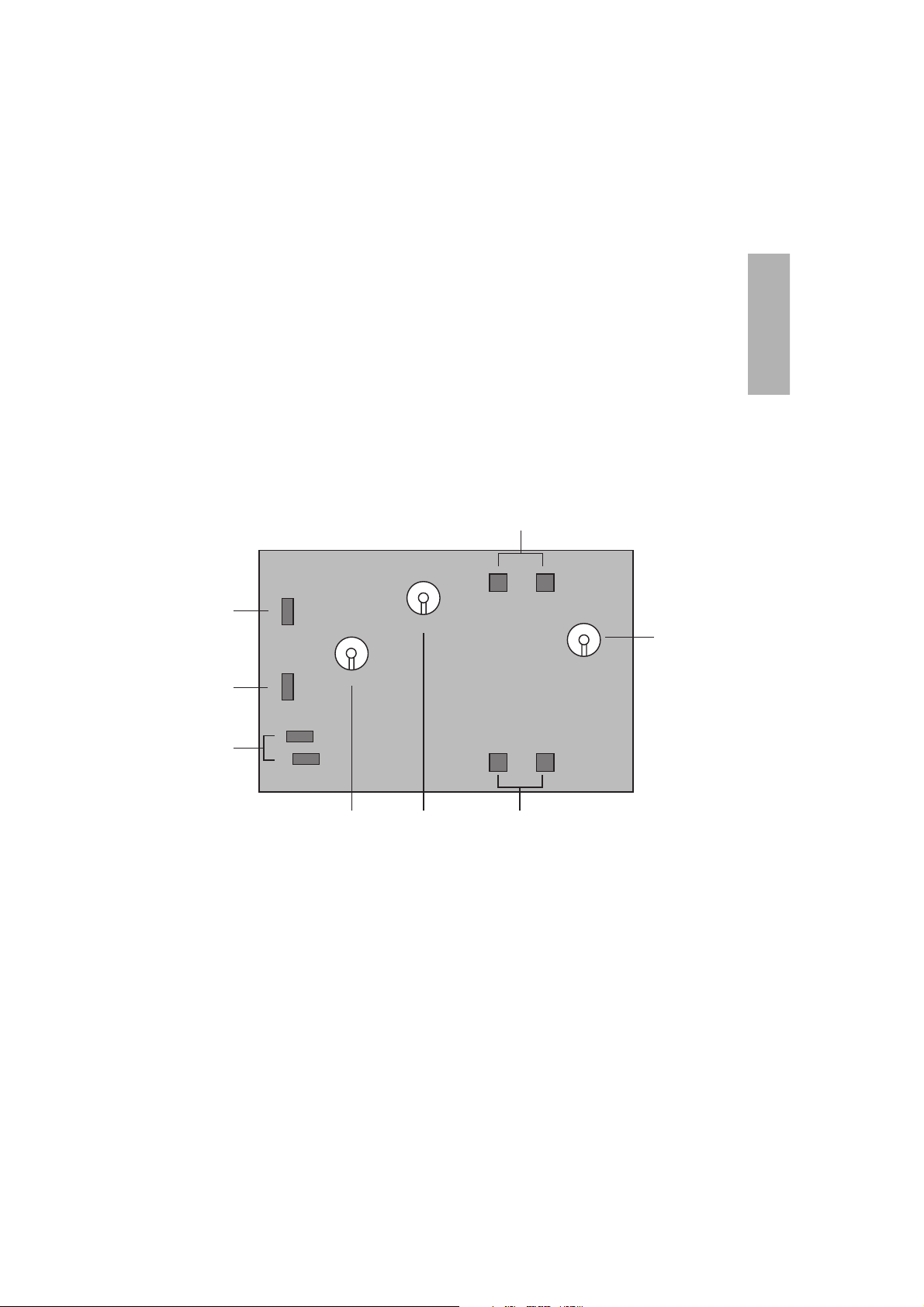
9. Ansicht Grundplatine
(1) Vorrangdämpfung 0 bis -40 dB
(2) Phantomspeisung einstellbar 0 bis 24 V
(3) Sicherung 3,15 A/F
(4) Ruhestromeinstellung
Achtung: Eine Veränderung der Ruhestromeinstellung darf nur vom
autorisiertem Fachpersonal vorgenommen werden!
(5) Gain MIC 1 (Vorverstärkung Mikrofon 1)
(6) Gain MIC 2 (Vorverstärkung Mikrofon 2)
(7) Brückenwiderstände (Diese müssen einseitig angelötet werden, wenn die
Ducking-Funktion gewünscht ist.)
(4)
(1) (2) (3)
(3)
(5)
(6)
(7)
PHANTOM
POWER
3,15 A/F
3,15 A/F
MIC 1 Gain MIC 2 Gain
Talk-Over
MIC 1
MIC 2
Page 12
12
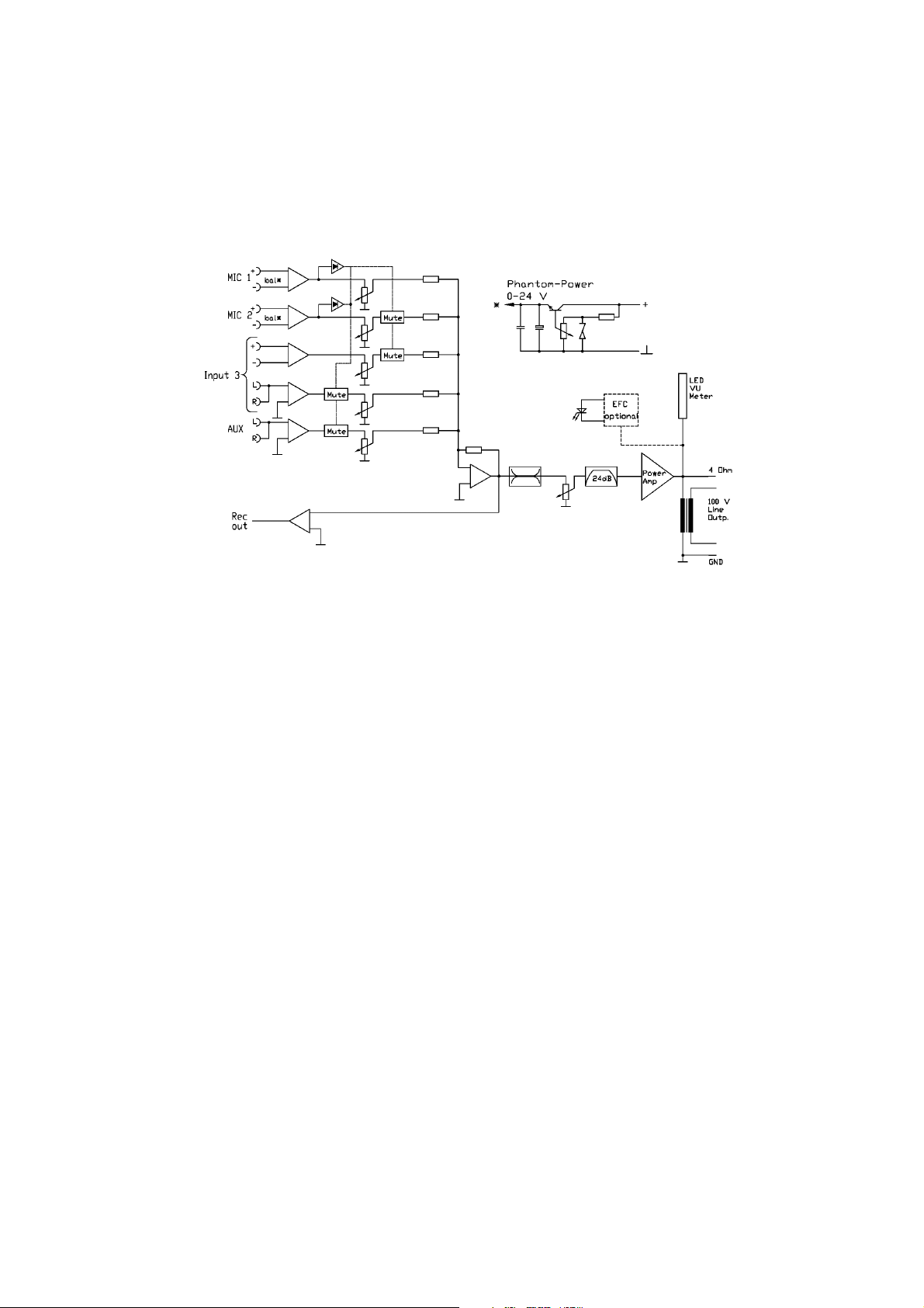
10. Blockschaltbild
Detaillierte Schaltbilder erhalten Sie auf Anfrage bei beyerdynamic.
Page 13

deutsch
13
Page 14

BEDIENUNGSANLEITUNG 5-KANAL-MISCHVERSTÄRKER MA 212
Sie haben sich für den 5-Kanal-Mischverstärker MA 212 von beyerdynamic
entschieden. Vielen Dank für Ihr Vertrauen.
Nehmen Sie sich bitte einige Minuten Zeit und lesen Sie diese Bedienungsanleitung
vor Inbetriebnahme aufmerksam durch.
1. Ausführung
MA 212 5-Kanal-Mischverstärker . . . . . . . . . . . . . . . . . . Best.-Nr. 452.971
Der Mischverstärker MA 212 hat 3 mischbare Mikrofoneingänge und 2 mischbare
Tonträgereingänge mit einem gemeinsamen Summenpegelsteller (Master) mit
Klangregelnetzwerk (Höhen- und Tiefenentzerrung). Über einen Insert kann mit
externen Effektgeräten das Signal bearbeitet werden. Die Mikrofoneingänge 1 und
2 können als Vorrangeingänge (sprachgesteuert) ausgelegt werden. Das laufende
Programm (Mikrofon und Tonträger) wird weich ausgeblendet.
2. Sicherheitshinweise
• LESEN Sie die Bedienungsanleitung/Produktinformation.
• BEWAHREN Sie diese Bedienungsanleitung/Produktinformation auf.
• BEFOLGEN Sie die aufgeführten Bedienungs- und Sicherheitshinweise.
• Das Gerät muss so aufgestellt werden, dass die Steckverbindung leicht zugänglich ist.
• Das Gerät muss an eine Netz-Steckdose mit Schutzkontakt angeschlossen werden.
• Setzen Sie das Gerät niemals Regen oder hoher Feuchtigkeit aus. Installieren Sie
es daher nicht in unmittelbarer Nähe von Swimming Pools, Duschanlagen,
feuchten Kellerräumen oder sonstigen Bereichen mit außergewöhnlich hoher
Luftfeuchtigkeit.
• Stellen Sie niemals mit Flüssigkeiten gefüllte Gegenstände (z.B. Vasen oder
Trinkgläser) auf das Gerät. Denn Flüssigkeiten in den Geräten können einen
Kurzschluss verursachen.
• Reinigen Sie das Gerät nur mit einem leicht feuchtem oder trockenem Tuch.
Verwenden Sie niemals Lösungsmittel, da diese die Oberfläche beschädigen.
• Installieren und betreiben Sie das Gerät auch niemals in unmittelbarer Nähe von
Heizkörpern, Beleuchtungsanlagen oder anderen wärmeerzeugenden Geräten.
• Verlegen Sie alle Kabel stets so, dass sie nicht durch scharfe Gegenstände
geknickt oder gar durchgetrennt werden können.
• Verlegen Sie alle Anschlusskabel so, dass niemand darüber stolpern und sich verletzen kann.
• Schalten Sie bei allen Arbeiten an den Ein- und Ausgängen die Stromzufuhr aus.
14
Page 15

deutsch
15
• Überprüfen Sie, ob die Anschlusswerte mit der vorhandenen Netzstromversorgung übereinstimmen. Bei Anschluss des Systems an die falsche Stromversorgung können ernsthafte Schäden entstehen. Eine falsche Netzspannung kann
das Gerät beschädigen oder einen elektrischen Schlag verursachen.
• Dieses Gerät benötigt eine ausreichende Ventilation. Decken Sie die Lüftungsöffnungen nicht ab. Wenn die Eigenwärme nicht abgeführt wird, kann das
Gerät beschädigt oder brennbare Materialien in unmittelbarer Nähe können
entzündet werden. Achten Sie daher darauf, dass die Luft durch die Lüftungsöffnungen frei zirkulieren kann und halten Sie brennbare Materialien fern.
• Wenn durch das Gerät ein Sicherungsdefekt oder ein Kurzschluss verursacht
wurde, nehmen Sie es vom Netz und lassen Sie es überprüfen und reparieren.
• Öffnen Sie nicht eigenmächtig das Gerät. Sie könnten einen elektrischen Schlag
erleiden. Überlassen Sie alle Servicearbeiten nur autorisiertem Fachpersonal.
• Berühren Sie den Kontaktstifte des Steckers nicht, nachdem Sie das Gerät vom
Netz getrennt haben, Sie könnten einen elektrischen Schlag erleiden.
• Stecken Sie keine Gegenstände in die Lüftungs- und andere Öffnungen. Sie
könnten das Gerät beschädigen und/oder sich verletzen.
• Setzen Sie das Gerät nicht ein, wenn der Netzstecker beschädigt ist.
Page 16

16
3. Bedien- und Kontrollelemente
Vorderseite
(1) Lautstärkeregler Mikrofoneingänge
(2) Lautstärkeregler Tonträgereingänge
(3) Klangregelung (Tiefen / Höhen)
(4) Lautstärkeregler Summe
(5) Anzeige für Überhitzung
(6) Pegelanzeige
(7) Ein- und Ausschalter
(8) Anzeige für Erdschluß
Ausschnitt Rückseite
(9) Insert für Signalbearbeitung
(10) NF-Erweiterungsausgang für weitere Endverstärker
(11) Aufnahmeausgang
(12)/(13) Tonträgereingänge
(14) Mikrofoneingänge mit Vorverstärkung (Gain)
(15) 100 V Lautsprecherausgang
(16) Niederohmiger Lautsprecherausgang (4 - 16 Ω)
-20
(8)
(15)(16)
Page 17

deutsch
17
4. Anschlüsse
4.1 Mikrofoneingänge
Auf der Geräterückseite befinden sich drei XLR-Mikrofonanschlüsse (14). Die
Mikrofone werden symmetrisch (Stift 2+3 NF, Stift 1 Abschirmung) angeschlossen.
Bei jedem Eingang kann die Eingangsempfindlichkeit (Gain) auf der Geräterückseite
eingestellt werden (1 - 100 mV). Die Eingangslautstärke wird auf der Vorderseite mit
den Lautstärkereglern (1) eingestellt. Die Mikrofoneingänge 1 und 2 können auf
Vorrang geschaltet werden (siehe Kapitel „4.1.1 Vorrangschaltung“).
Achtung:
Alle Mikrofoneingänge haben eine einstellbare Phantomspeisung von 0 bis
+24 V. Wenn Sie Geräte mit unsymmetrischen Ausgängen anschließen, muß
ein Koppelkondensator eingefügt werden, bzw. die Phantomspeisung abgeschaltet werden. Bei Mischbetrieb von Kondensatormikrofonen und Geräten mit unsymmetrischen Ausgängen empfehlen wir Ihnen, die Phantomspeisung je nach genutztem Eingang abzuschalten.
4.1.1 Vorrangschaltung
Die Priorität der bevorrechtigten Mikrofoneingänge ist sprachgesteuert (Ducking-
Funktion). Im Auslieferungszustand ist diese Funktion nicht aktiv. Falls die DuckingFunktion gewünscht ist, müssen die Brückenwiderstände auf der Grundplatine einseitig angelötet werden (siehe Kapitel „9. Ansicht Grundplatine“). Eine
Ausblendung erfolgt durch das Besprechen des an einem der bevorrechtigten
Mikrofoneingänge angeschlossenen Mikrofons. Die Ducking-Funktion ist auch bei
zugeregeltem Eingangsregler (falls ein Mikrofon angeschlossen ist, muß der Schalter
am Mikrofon auf „Aus“ geschaltet werden) aktiv. Als Mikrofon sind ein Handmikrofon oder eine Tischsprechstelle möglich.
Mikrofon 1 hat den obersten Vorrang vor Mikrofon 2. Beide Mikrofone blenden
Mikrofon 3 und die Tonträgereingänge aus. Die Ausblendung ist von 0 bis -40 dB auf
der Grundplatine einstellbar (siehe Kapitel „9. Ansicht Grundplatine“).
4.2 Tonträgereingänge
Zwei regelbare Cinch-Tonträgeranschlüsse für den Eingang und ein
Cinchanschluß für den Aufnahmeausgang befinden sich auf der Geräterückseite des
Mischverstärkers. Die Anschlüsse werden unsymmetrisch angeschlossen und eignen
sich für Stereo-Träger (L + R werden intern über Widerstandsmatrix zusammengeschaltet). Am Aufnahmeausgang steht das Summensignal aus allen Eingängen zur
Verfügung; unabhängig von Klangregelnetzwerk (3) und Lautstärkeregler Summe (4).
Page 18

18
4.3 NF-Erweiterungsausgang (0 dB)
Die Ausgangsbuchse (10) ist unsymmetrisch beschaltet. Dieser Ausgang dient
zum Ansteuern von weiteren Endverstärkern. Haben diese Verstärker einen symmetrischen Eingang wird die Abschirmung mit einem der Signal-Eingänge gebrückt
(Stift 1 mit 3). Der NF-Erweiterungsausgang (10) erlaubt die Auswahl zwischen:
1 = Mikrofonsumme
2 = Mikrofon- und Tonträgersumme vor Insert und Lautstärkeregelung
3 = Mikrofon- und Tonträgersumme nach Insert und Lautstärkeregelung
Die Auswahl erfolgt über entsprechende Programmierbrücken (siehe Kapitel
„9. Ansicht Grundplatine“).
4.4 Lautsprecheranschluß
Die 100 V-Lautsprecher werden an der Lautsprecherbuchse (15) ange-
schlossen. Die Ausgangsspannung beträgt bei Vollaussteuerung an diesen Buchsen
100 V.
Niederohmige Lautsprecher mit einer Impedanz von 4 bis 16 Ω können Sie an die
Klemmen 4-16 und COM der Klemmleiste (16) anschließen.
Achtung:
Ein gleichzeitiger Betrieb von 100 V-Lautsprechern und niederohmigen
Lautsprechern führt zur Zerstörung des Verstärkers!
Der Mischverstärker MA 212 ist zum Anschluss von Lautsprechern mit 100 V-Anpassungsübertragern geeignet. Werden diese Lautsprecher an einen 100 V-Verstärkerausgang angeschlossen, erhalten sie die volle Leistung entsprechend der
Anpassung. Die Summe der angeschlossenen Lautsprecher bzw. deren Leistungsanpassung ergeben die Gesamtleistungsaufnahme. Diese darf nicht über der 100 VVerstärkerleistung liegen, ansonsten führt dies zur Zerstörung des Verstärkers.
4.5 Record Out - Aufnahmeausgang
Die Aufnahmebuchse (11) ist unsymmetrisch beschaltet (0 dB). Sie dient zum
Anschluss von Aufzeichnungsgeräten. Das Signal, das zur Aufnahme zur Verfügung
steht, ist die Summe der Mikrofon- und Tonträgereingänge vor der Klang- und Lautstärkenregelung.
4.6 Insert
Die Insert-Buchse (9) ist unsymmetrisch beschaltet. Sie dient zum Anschluss
externer Signalbearbeitungsgeräte wie z.B. Equalizer, Shifter etc. Die Signalsumme
kann vor und hinter der Klangregelung ausgewählt werden (siehe Kapitel
„9. Ansicht Grundplatine“).
Wenn der Stecker nicht eingesteckt ist, ist der Signalweg durchgeschaltet.
Page 19

deutsch
19
4.7 Netzanschluß
Das Netzkabel ist fest angeschlossen und mit einem Schutzkontakt versehen.
5. Inbetriebnahme
Nachdem alle Anschlüsse (Netz, Mikrofon, Lautsprecher etc.) hergestellt wor-
den sind, gehen Sie wie folgt vor, um das System in Betrieb zu nehmen:
1. Stellen Sie alle Lautstärkeregler auf „0“.
2. Schalten Sie das Gerät ein, das als Signalquelle dient.
3. Schalten Sie den Mischverstärker MA 212 mit dem Ein- und Ausschalter (7) ein.
4. Drehen Sie den/die betreffenden Lautstärkeregler halb auf, während der
Ausgangs-Pegelregler der Signalquelle (falls vorhanden) voll zugedreht ist. Dabei
sollte kein hörbarer Brummton auftreten. Wenn Sie einen Brummton wahrnehmen, überprüfen Sie nochmals die Verbindung zwischen Tonquelle und
Mischverstärker.
5. Mit den Lautstärkereglern Mikrofon (1) regeln Sie die Lautstärke der einzelnen
Mikrofoneingänge.
6. Mit dem Lautstärkeregler Summe (4) wird die gewünschte Lautstärke im Saal
eingestellt.
7. Die Tonträgerlautstärke wird unabhängig von der Summe mit dem Lautstärke-
regler Tonträger (2) eingestellt.
8. Aktivieren Sie ein Signal.
9. Drehen Sie langsam den Ausgangs-Pegelsteller der Signalquelle auf, bis das Sig-
nal aus dem an den Verstärker angeschlossenen Lautsprecher zu hören ist. Sie
können den Systempegel einstellen, sobald sich der Klang normal anhört.
10. Sollten Sie eine Vorrangfunktion der Mikrofoneingänge 1 und 2 wünschen, muß
diese aktiviert werden (siehe Kapitel „4.1.1 Vorrangschaltung“).
6. Fehlercheckliste
• Netzschalter nicht eingeschaltet
• Netzstecker nicht angeschlossen
• Netzstromversorgung defekt
• Sicherung defekt
• Netzschalter einschalten
• Netzstecker ans Netz anschließen
• Ursache feststellen und beheben
• Sicherung ggf. austauschen
• Lautstärkeregler aufdrehen
• Kurzschluß feststellen und beseitigen
• Ausgangspegel der Signalquelle (für
Tonträger) reduzieren
• Überprüfen und sicherstellen, daß die
Impedanz 4 Ω nicht unterschreitet
• Lautsprechernetz überprüfen, ggf.
Lautsprecher abklemmen
Kein oder verzerrter Ton
Keine Wiedergabe
Fehler Mögliche Ursache Lösung
• Lautstärkeregler auf 0
• Kurzschluß am Lautsprecherausgang
• Eingangspegel zu hoch
• Zu geringe Lautsprecher-Impedanz
• Gesamtleistung des Lautsprechernetzes
überschreitet die des Verstärkers
Page 20

20
• Die Signalquelle erzeugt den Brummton.
• Eingangssignalleitung wurde in unmittelbarer Nähe zu Netzkabeln verlegt.
• Es bestehen HF-Einstrahlungen durch
nahe Fernsehsender. Störungen dieser
Art sind durch ständige Veränderungen
entsprechend der Veränderungen des
Fernsehbildes gekennzeichnet.
• Überprüfen, ob die Signalquelle
defekt oder falsch angeschlossen ist.
• Signalleitungen anders verlegen.
• Versuchen Sie, das Problem durch
andere Kabel oder Masseverbindungen zu lösen. Versuchen Sie, das
Problem durch Einsetzen eines
0,1 µF-Kondensators zu lösen.
Alternativ kann es auch helfen, die
Eingangs-Signalleitungen von den
Netzkabeln getrennt zu führen.
• Der Ausgangssignalpegel der Signalquelle
ist zu hoch, während der Lautstärkeregler
des Verstärkers zum Ausgleich zu niedrig
eingestellt ist.
• Die Signalquelle selbst gibt ein verzerrtes
Signal ab.
• Reduzieren Sie den Ausgangspegel
und erhöhen Sie die Lautstärke am
Verstärker.
• Ersetzen oder reparieren Sie die
defekte Komponente.
Verzerrungen am
Lautsprecherausgang
Störsignal am
Lautsprecherausgang
Fehler Mögliche Ursache Lösung
7. Zubehör - optional
Verschiedene Tischsprechstellen und Mikrofone
ZA 2 Transparente Abdeckung für Bedienelemente . . . . . . Best.-Nr. 453.005
ZE 100 Nachrüstsatz Erdschlußüberwachung . . . . . . . . . . . . . Best.-Nr. 453.781
8. Technische Daten
Frequenzgang . . . . . . . . . . . . . . . 55 - 18.000 Hz
Klirrfaktor . . . . . . . . . . . . . . . . . . ≤ 0,08%
Signal-Rauschabstand . . . . . . . . . -75 dB
Mikrofoneingänge
Kopplung. . . . . . . . . . . . . . . . . . . elektronisch symmetriert
Eingangsimpedanz . . . . . . . . . . . 600 Ω
Vorverstärkung . . . . . . . . . . . . . . 1 - 100 mV, einstellbar
Phantomspeisung . . . . . . . . . . . . 0 - 24 V, einstellbar für Mikro 1 und Mikro 2
Anschluss . . . . . . . . . . . . . . . . . . . 3-pol. XLR
Prioritätsschaltung. . . . . . . . . . . . Ducking-Funktion auf Mikro 1 und 2, 0 - -40 dB,
einstellbar; erste Priorität für Mikro 1 und
zweite Priorität für Mikro 2 über die zwei
Line-Eingänge
• Die Signalquelle erzeugt den Brummton.
• Eingangssignalleitung wurde in unmittelbarer Nähe zu Netzkabeln verlegt.
• Fehler der unsym. Leitungsführung.
• Überprüfen, ob die Signalquelle
defekt oder falsch angeschlossen ist.
• Signalleitungen anders verlegen.
• Schließen Sie die Eingangsquelle
symmetrisch an.
Brummstörungen am
Lautsprecherausgang
Page 21

deutsch
21
Line-Eingänge
Kopplung. . . . . . . . . . . . . . . . . . . unsymmetrisch
Eingangsimpedanz . . . . . . . . . . . 47 kΩ
Eingangspegel . . . . . . . . . . . . . . . 250 mV (-10 dBm) und 775 mV (0 dBm)
Anschluss . . . . . . . . . . . . . . . . . . . 2 x Cinch je Line-Eingang
Klangregelung
Tiefen. . . . . . . . . . . . . . . . . . . . . . 100 Hz, ± 9 dB
Höhen . . . . . . . . . . . . . . . . . . . . . 10 kHz, ± 9 dB
Tiefenfilter. . . . . . . . . . . . . . . . . . 24 dB/55 Hz
Höhenfilter . . . . . . . . . . . . . . . . . 24 dB/18 kHz
Ausgänge
Ausgangsleistung . . . . . . . . . . . . 125 W (Sinusdauerton)
Ausgangsimpedanz . . . . . . . . . . . 4 Ω oder 100 V erdfrei
Record-Ausgang
Kopplung. . . . . . . . . . . . . . . . . . . unsymmetrisch
Ausgangsimpedanz . . . . . . . . . . . 1 kΩ
Ausgangspegel . . . . . . . . . . . . . . 775 mV (0 dBm)
Anschluss . . . . . . . . . . . . . . . . . . . 1 x Cinch
Erweiterungs-Ausgang (Slave)
Kopplung. . . . . . . . . . . . . . . . . . . unsymmetrisch
Signalweg . . . . . . . . . . . . . . . . . . einstellbar
Ausgangsimpedanz . . . . . . . . . . . 600 Ω
Ausgangspegel . . . . . . . . . . . . . . 775 mV (0 dBm)
Anschluss . . . . . . . . . . . . . . . . . . . 1 x Cinch
Insert
Kopplung. . . . . . . . . . . . . . . . . . . unsymmetrisch
Ausgangssimpedanz (Send). . . . . 600 Ω
Eingangsimpedanz (Return) . . . . 10 kΩ
Ausgangspegel (Send). . . . . . . . . 775 mV (0 dBm)
Eingangspegel (Return). . . . . . . . 775 mV (0 dBm)
Anschluss . . . . . . . . . . . . . . . . . . . 6,35 mm Klinke
Belegung . . . . . . . . . . . . . . . . . . . Spitze = Send; Ring = Return
Netzspannung . . . . . . . . . . . . . . . 230 V
Abmessungen . . . . . . . . . . . . . . . 19"/2 HE (B x H x T / 435 x 88 x 190 mm)
Gewicht . . . . . . . . . . . . . . . . . . . . 10 kg
Page 22

22
9. Ansicht Grundplatine
(1) Vorrangdämpfung 0 bis -40 dB
(2) Slave Out / Erweiterungsausgang
1 = Mikrofonsumme
2 = Mikrofon- und Tonträgersumme vor Insert und Lautstärkeregelung
3 = Mikrofon- und Tonträgersumme nach Insert und Lautstärkeregelung
(3) SEND
1 = Vor-Klangregelung
2 = Nach-Klangregelung
(4) Sicherung A/F (5 A/F)
(5) Gleichstromeinstellung
(6) Ruhestromeinstellung
Achtung: Eine Veränderung der Gleichstrom- und Ruhestromeinstellung
darf nur vom autorisiertem Fachpersonal vorgenommen werden.
(7) Phantomspeisung einstellbar 0 bis 24 V
(8) Meßpunkt der Phantomspannung
(9) Brückenwiderstände (Diese müssen einseitig angelötet werden, wenn die
Ducking-Funktion gewünscht ist.)
GAIN GAIN GAIN
(6)(7)
(8)
Phantom
TP
Voltage
Phantom
(9)
Talkover
Level
(1) (2) (3)
SLAVE OUT
3
2
1
SEND
1
2
BIAS
DC
OFFSET
(5)
(4)
Page 23

deutsch
23
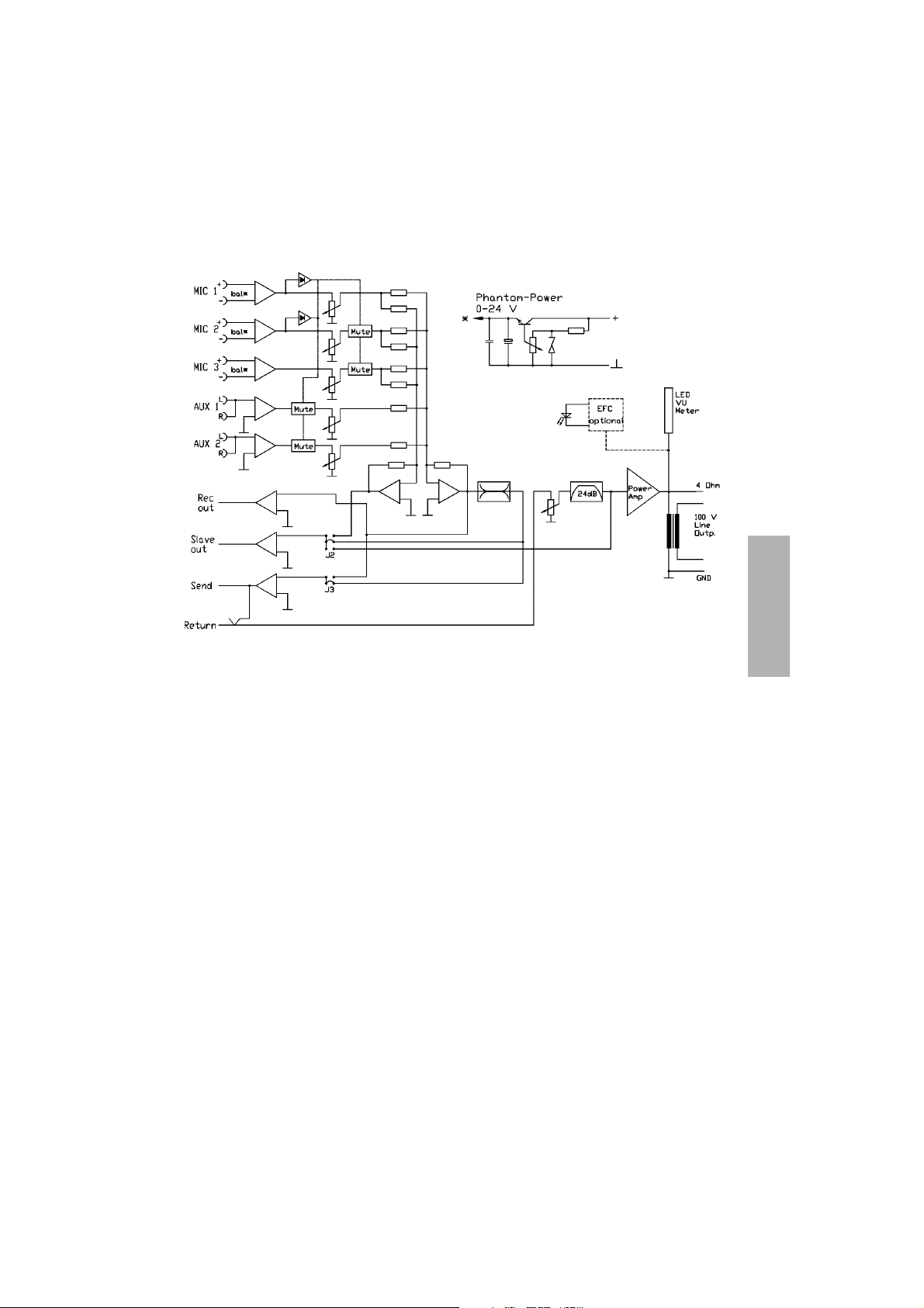
10. Blockschaltbild
Detaillierte Schaltbilder erhalten Sie auf Anfrage bei beyerdynamic.
Page 24

24
OPERATING INSTRUCTIONS MA 206 4-CHANNEL MIXER AMPLIFIER
Thank you for selecting the MA 206 4-channel mixer amplifier. Please take
some time to read carefully through these operating instructions before setting up
the equipment.
1. Model
MA 206 4-Channel Mixer Amplifier . . . . . . . . . . . . . . . . Order # 452.963
The MA 206 mixer amplifier has 2 microphone inputs, 1 universal input (microphone,
auxiliary) and 1 auxiliary input with a common master control with treble and bass
control. The microphone inputs 1 and 2 can be used as voice-controlled priority
inputs. The current programme (microphone or line) is gently faded out.
2. Safety Information
• READ the Operating Instructions / Product Information sheet.
• KEEP these Operating Instructions / Product Information safe.
• COMPLY with the Operating and Safety instructions listed.
• The equipment must be set up so that the plug connector is easily accessible.
• The equipment must be connected to a mains socket that has an earth contact.
• Never expose the equipment to rain or a high level of humidity. For this reason
do not install it in the immediate vicinity of swimming pools, showers, damp
basement rooms or other areas with unusually high atmospheric humidity.
• Never place objects containing liquid (e.g. vases or drinking glasses) on the
equipment. Liquids in the equipment could cause a short circuit.
• Only clean the equipment with a slightly damp or dry cloth. Never use solvents
as these damage the surface.
• Never install and operate the equipment close to radiators, lighting equipment
or other heat generating equipment.
• Always run all cables so that they cannot be damaged or severed by sharp objects.
• Lay all connection cables so that they do not present a trip hazard.
• Whenever working on the equipment switch off all inputs and outputs to the
power supply.
• Check whether the connection figures comply with the existing mains supply.
Serious damage could occur due to connecting the system to the wrong power
supply. An incorrect mains voltage could damage the equipment or cause an
electric shock.
• This equipment needs adequate ventilation. Do not cover ventilation grilles. If
the heat it generates cannot be dissipated, the equipment could be damaged or
flammable materials in its immediate vicinity could be ignited. Take care to
ensure that the air can circulate freely through the ventilation grilles and keep
Page 25

english
25
flammable materials away.
• If the equipment causes a blown fuse or a short circuit, disconnect it from the
mains and have it checked and repaired.
• Do not open the equipment without authorisation. You could receive an electric
shock. Leave all service work to authorised expert personnel.
• Do not touch the contact pins of the plug even after you have disconnected the
equipment from the mains. You could receive an electric shock.
• Do not insert objects into the ventilation grilles or other openings. You could
damage the equipment and/or injure yourself.
• Do not use the equipment if the mains plug is damaged.
Page 26

26
3. Controls and Indicators
Front view
(1) Volume control microphone inputs
(2) Volume control universal input
(3) Volume control auxiliary input
(4) Equalisation (bass / treble)
(5) Volume control master
(6) Level indication
(7) Operating control LED
(8) ON/OFF-switch
(9) LED to indicate earth fault
Rear view (detailed view)
(10) 100 V loudspeaker output
(11) Low-impedance loudspeaker output (4 - 16 Ω)
(12) Record output
(13) Auxiliary input
(14) Universal input for auxiliary
(15) Universal input for microphone (unbalanced)
(16) Microphone inputs
06060606 0600600
6
1
2
3
4
5
7
8
9
10
Page 27

english
27
4. Connections
4.1 Microphone inputs
On the rear there are two XLR-connections (16). The microphone connection is
balanced (pin 2+3 signal AF, pin 1 ground shield). For each input the input gain
(1 - 100 mV) can be adjusted internally on the printed circuit board (refer to chapter
“9. Printed circuit board”). The input volume is adjusted on the front using the
volume control (1). The microphone inputs 1 and 2 can be switched to priority (refer
to chapter “4.1.1 Priority switching”).
Caution:
All balanced microphone inputs have an adjustable phantom power from 0
to +24 V. If you connect microphones or wireless microphone receivers with
unbalanced outputs you have to insert a coupling capacitor or the mixer
amplifier will be seriously damaged.
4.1.1 Priority switching
The priority of the privileged microphone inputs is voice-controlled (ducking
function). The unit is delivered with this function being deactivated. If the ducking
function is desired, the bridge resistors on the printed circuit board have to be soldered (refer to chapter “9. Top view of the printed circuit board”). The programme
fades out when someone is speaking into the microphone. Possible microphones are
a handheld mic or a desktop microphone unit.
Microphone 1 has priority over microphone 2. Both microphones fade out the universal input and the auxiliary input. The fade-out can be adjusted from 0 to -40 dB
on the printed circuit board (refer to chapter “9. Top view of the printed circuit
board”).
4.2 Universal input
The universal input is a 1/4" jack for the connection of a microphone (unbal-
anced) or a low-level line input (RCA). The input gain for the microphone
(3 mV) and the low-level input (250 mV/-10 dB) is fixed.
4.3 Auxiliary input
On the rear of the mixer amplifier there is one adjustable RCA (phono) connec-
tion for input and one RCA (phono) connection for the record output. The connections are unbalanced and suitable for stereo carriers (L + R are internally switched
together via an impedance matrix). The master signal from the auxiliary and microphone inputs is available at the record output; independent of the equalisation (bass
and treble) (4) and the master volume control (5).
Page 28

28
4.4 Loudspeaker connection
The loudspeaker is connected to the loudspeaker terminal board (10). The
output voltage of this socket is 100 V at full modulation. Low-impedance loudspeakers with an impedance of 4 to 16 Ω can be connected to the terminals
4 - 16 and COM of the terminal board (11).
Caution:
A simultaneous operation of 100 V and low-impedance loudspeakers will
destroy the amplifier!
The MA 206 mixer amplifier is suitable for the connection of loudspeakers with
100 V-matching transformer. If these loudspeakers are connected to a 100 V amplifier output, they receive the power depending on the matching. All the connected
loudspeakers or their power matching result in the total power consumption. The
total power consumption must not exceed the rated amplifier power, or the amplifier may be damaged.
4.5 Record Output
The record output (12) is unbalanced (0 dB), for the connection of recorders.
The audio signal is the master of the microphone and auxiliary inputs before the
equalisation and volume controls.
4.6 Mains connection
The mains cable is fixed and equipped with a ground contact.
5. Setting up
After all connections such as mains, microphone and loudspeakers have been
completed; follow these steps to bring the system up:
1. Turn all volume controls to “0”.
2. Turn on the source equipment.
3. Turn on the MA 206 mixer amplifier with the ON/OFF-switch (8).
4. Turn the corresponding volume control half up, with the output level control of
the source equipment turned down. There should be no audible hum. If hum is
heard, check the connections between the sound source and the mixer amplifier.
5. Using the volume control microphone (1) you can adjust the volume of the individual microphone inputs.
6. Using the volume control master (5) the desired volume in the room is adjusted.
7. The volume of the sound carrier input is adjusted with the volume control (3)
independent of the master volume control.
8. Activate a signal.
Page 29

english
29
9. Slowly turn up the source equipment input gain controls until you begin to hear
the sound source from the loudspeakers connected to the amplifier. If the sound
is clear and undistorted, adjust the system level to the desired listening levels.
10. If you want the ducking function of the microphone inputs 1 and 2, it has to be
activated (refer to chapter “4.1.1 Priority switching”).
6. Trouble Shooting
• The power switch is not switched to the
ON position
• The AC plug is not connected
• The AC power source is defective
• Defective fuse
• Switch the power switch to the ON
position
• Connect the AC plug properly
• Locate and correct the AC mains
problem
• Check and exchange the fuse
• Turn the volume control up
• Locate and correct the short circuit
• Reduce output level of the sound
source (for sound carriers)
• Make sure that the impedance is not
below 4 Ω
• Check the loudspeakers, disconnect
one if necessary
• The source itself has a hum
• The input wiring passes near AC mains
wiring
• Defect in the unbalanced wiring
• Determine if the source is defective
or wired incorrectly and correct
• Reroute the input wiring
• Balanced connection to the input
source
Hum in the output
No or distorted sound
No reproduction
Problem Possible Cause Solution
• Volume control is set to “0”
• There is a short circuit on the loudspeaker
output
• Input level is too high
• The loudspeaker impedance is too low
• There is too much loudspeaker load on the
output
• The source itself has a hum
• The input wiring passes near AC mains
wiring or wiring to lighting dimmers
• There is pickup of RFI (radio frequency
interferences) from TV transmissions. This
kind of interference sounds like power
line related buzz, but tends to change in
character every few seconds due to
changes in the video image.
• Determine if the source is defective
or wired incorrectly and correct.
• Reroute the input wiring
• Try different cabling or grounding
techniques. Try to solve the problem
by using the 0.1 µF capacitor connected
to bypass the shield. Try different
routing of input and power cables.
• The source output is set too high and the
gain control of the amplifier is turned way
down to compensate
• The source itself is distorted
• Reduce the source output level and
increase the setting of the gain
control of the amplifier
• Try a different source and/or have the
source repaired
Distortion in the
output
Buzz in the output
Page 30

30
7. Optional Accessories
Different desktop microphone units and microphones
ZA 2 Transparent cover for the operating controls
and indicators . . . . . . . . . . . . . . . . . . . . . . . . . . . . . . . Order # 453.005
ZE 100 Retrofit item for earth-fault control . . . . . . . . . . . . . . Order # 453.781
8. Technical Specifications
Frequency response . . . . . . . . . . . . . 55 - 18,000 Hz
Distortion (THD) . . . . . . . . . . . . . . . . ≤ 0.08%
Signal to noise ratio . . . . . . . . . . . . . -75 dB
Microphone inputs
Characteristics . . . . . . . . . . . . . . . . . . electronically balanced
Input impedance. . . . . . . . . . . . . . . . 600 Ω
Pre-amplification . . . . . . . . . . . . . . . 1 - 100 mV (-58 dBm - -18 dBm), adjustable
Phantom power . . . . . . . . . . . . . . . . 0 - 24 V, adjustable for Mic 1 and 2
Connection . . . . . . . . . . . . . . . . . . . . 3-pin XLR
Priority control . . . . . . . . . . . . . . . . . Ducking function on Mic 1 and 2,
0 - -40 dB attenuation, adjustable
first priority for Mic 1,
second priority for Mic 2 over the other
inputs
Universal input
Microphone
Characteristics . . . . . . . . . . . . . . . . . . unbalanced
Input impedance. . . . . . . . . . . . . . . . 2 kΩ
Pre-amplification . . . . . . . . . . . . . . . 3 mV, fixed
Connection . . . . . . . . . . . . . . . . . . . . 1/4" jack; top = AF signal; shaft = AF ground
AUX
Characteristics . . . . . . . . . . . . . . . . . . unbalanced
Input impedance. . . . . . . . . . . . . . . . 47 kΩ
Pre-amplification . . . . . . . . . . . . . . . 250 mV (-10 dBm), fixed
Connection . . . . . . . . . . . . . . . . . . . . 2 x RCA (phono)
Line input
Characteristics . . . . . . . . . . . . . . . . . . unbalanced
Input impedance. . . . . . . . . . . . . . . . 47 kΩ
Input level. . . . . . . . . . . . . . . . . . . . . 775 mV (0 dBm)
Connection . . . . . . . . . . . . . . . . . . . . 2 x RCA (phono)
Equalisation
Bass . . . . . . . . . . . . . . . . . . . . . . . . . . 100 Hz, ± 9 dB
Treble . . . . . . . . . . . . . . . . . . . . . . . . 10 kHz, ± 9 dB
Bass filter . . . . . . . . . . . . . . . . . . . . . 24 dB/55 Hz
Treble filter. . . . . . . . . . . . . . . . . . . . 24 dB/18 kHz
Page 31

english
31
Outputs
Output power. . . . . . . . . . . . . . . . . . 60 W
Output impedance . . . . . . . . . . . . . . 4 Ω or 100 V ungrounded
Record output
Characteristics . . . . . . . . . . . . . . . . . . unbalanced
Output impedance . . . . . . . . . . . . . . 1 kΩ
Output level . . . . . . . . . . . . . . . . . . . 775 mV (0 dBm)
Connection . . . . . . . . . . . . . . . . . . . . 1 x RCA (phono)
Mains voltage . . . . . . . . . . . . . . . . . . 230 V
Dimensions . . . . . . . . . . . . . . . . . . . . 19"/2 HU Rack Units
(H x W x D / 88 x 435 x 190 mm)
Weight . . . . . . . . . . . . . . . . . . . . . . . 7 kg
9. Top View of the Printed Circuit Board
(1) Priority attenuation 0 to -40 dB
(2) Phantom power adjustable 0 to 24 V
(3) Fuse 3.15 A/F
(4) Quiescent current control
CAUTION: Changes of the adjusted quiescent current must only be
carried out by authorised service personnnel.
(5) Gain MIC 1
(6) Gain MIC 2
(7) Bridge resistors (if the ducking function is to be activated they have to be
soldered on one side)
(4)
(1) (2) (3)
(3)
(5)
(6)
(7)
PHANTOM
POWER
3,15 A/F
3,15 A/F
MIC 1 Gain MIC 2 Gain
Talk-Over
MIC 1
MIC 2
Page 32

32
10. Wiring Diagram
Detailed wiring diagrams are available upon request.
Page 33

english
33
Page 34

34
OPERATING INSTRUCTIONS MA 212 5-CHANNEL MIXER AMPLIFIER
Thank you for selecting the MA 212 5-channel mixer amplifier. Please take
some time to read carefully through these operating instructions before setting up
the equipment.
1. Model
MA 212 5-channel mixer amplifier. . . . . . . . . . . . . . . . . Order # 452.971
The MA 212 mixer amplifier has 3 microphone inputs and 2 auxiliary inputs with a
common master control and treble and bass equalisation. The signal can be processed
with external effect devices via an insert. The microphone inputs 1 and 2 can be
used as voice-controlled priority inputs. The current programme (microphone or
line) is gently faded out.
2. Safety Information
• READ the Operating Instructions / Product Information sheet.
• KEEP these Operating Instructions / Product Information safe.
• COMPLY with the Operating and Safety instructions listed.
• The equipment must be set up so that the plug connector is easily accessible.
• The equipment must be connected to a mains socket that has an earth contact.
• Never expose the equipment to rain or a high level of humidity. For this reason
do not install it in the immediate vicinity of swimming pools, showers, damp
basement rooms or other areas with unusually high atmospheric humidity.
• Never place objects containing liquid (e.g. vases or drinking glasses) on the
equipment. Liquids in the equipment could cause a short circuit.
• Only clean the equipment with a slightly damp or dry cloth. Never use solvents
as these damage the surface.
• Never install and operate the equipment close to radiators, lighting equipment
or other heat generating equipment.
• Always run all cables so that they cannot be damaged or severed by sharp objects.
• Lay all connection cables so that they do not present a trip hazard.
• Whenever working on the equipment switch off all inputs and outputs to the
power supply.
• Check whether the connection figures comply with the existing mains supply.
Serious damage could occur due to connecting the system to the wrong power
supply. An incorrect mains voltage could damage the equipment or cause an
electric shock.
• This equipment needs adequate ventilation. Do not cover ventilation grilles. If
the heat it generates cannot be dissipated, the equipment could be damaged or
flammable materials in its immediate vicinity could be ignited. Take care to
Page 35

english
35
ensure that the air can circulate freely through the ventilation grilles and keep
flammable materials away.
• If the equipment causes a blown fuse or a short circuit, disconnect it from the
mains and have it checked and repaired.
• Do not open the equipment without authorisation. You could receive an electric
shock. Leave all service work to authorised expert personnel.
• Do not touch the contact pins of the plug even after you have disconnected the
equipment from the mains. You could receive an electric shock.
• Do not insert objects into the ventilation grilles or other openings. You could
damage the equipment and/or injure yourself.
• Do not use the equipment if the mains plug is damaged.
Page 36

36
3. Controls and Indicators
Front view
(1) Volume control microphone inputs
(2) Volume control universal input
(3) Equalisation (bass / treble)
(4) Volume control master
(5) Indication for overheating
(6) Level indication
(7) ON/OFF-switch
(8) LED to indicate earth fault
Rear view (detailed view)
(9) Insert for signal processing
(10) AF output for further power amplifiers
(11) Record output
(12)/(13) Auxiliary inputs
(14) Microphone inputs with gain
(15) 100 V loudspeaker output
(16) Low-impedance loudspeaker output (4 - 16 Ω)
-20
(8)
(15)(16)
Page 37

english
37
4. Connections
4.1 Microphone inputs
On the rear there are three XLR-connections (14). The microphone connection
is balanced (pin 2+3 AF, pin 1 shield). For each input the input gain (1 - 100 mV) can
be adjusted on the rear. The input volume is adjusted on the front using the volume
control (1). The microphone inputs 1 and 2 can be switched to priority (refer to
chapter “4.1.1 Priority switching”).
Caution:
All balanced microphone inputs have an adjustable phantom power from
0 to +24 V. If you connect devices with unbalanced outputs switch off the
phantom power or add a coupling capacitor. If condenser microphones and
devices with unbalanced outputs are used simultaneously we recommend
to switch off the phantom power according to the used input.
4.1.1 Priority switching
The priority of the privileged microphone inputs is voice-controlled (ducking
function). The unit is delivered with this function being deactivated.
If the ducking function is desired, the bridge resistors on the printed circuit board
have to be soldered (refer to chapter “9. Top view of the printed circuit board”). The
programme fades out when someone is speaking into the microphone connected to
one of the privileged microphone inputs. The ducking function is also activated,
when the input control is turned down (if a microphone is connected, the switch of
the microphone must be switched to the “Off” position). Possible microphones are
a handheld mic or a desktop microphone unit.
Microphone 1 has priority over microphone 2. Both microphones fade out
microphone 3 and the auxiliary input. The fade-out can be adjusted from 0 to
-40 dB on the printed circuit board (refer to chapter “9. Top view of the printed
circuit board”).
4.2 Auxiliary inputs
On the rear of the mixer amplifier there are two adjustable separate RCA
(phono) connections for input and one RCA (phono) connection for the record
output. The connections are unbalanced and suitable for stereo carriers (L + R are
internally switched together via an impedance matrix). The master signal from all
inputs is available at the record output; independent of the equalisation (bass and
treble) (3) and the master volume control (4).
Page 38

38
4.3 Additional AF output (0 dB)
The additional AF output (10) is unbalanced. It serves for controlling other
power amplifiers. If these amplifiers have a balanced input, the shield is bridged with
one of the signal inputs (pin 1 and 3). The AF output (10) allows the selection
between:
1 = Microphone master
2 = Microphone and line master before insert and volume control
3 = Microphone and line master after insert and volume control
The selection is done using the jumpers (refer to chapter “9. Top view printed
circuit board”).
4.4 Loudspeaker connection
The loudspeaker is connected to the loudspeaker socket (15). The output
voltage of this socket is 100 V at full modulation. Low-impedance loudspeakers with
an impedance of 4 to 16 Ω can be connected to the terminals 4 - 16 and COM of the
terminal board (16).
Caution:
A simultaneous operation of 100 V and low-impedance loudspeakers will
destroy the amplifier!
The MA 212 mixer amplifier is suitable for the connection of loudspeakers with 100
V-matching transformer. If these loudspeakers are connected to a 100 V amplifier
output, they receive the full power depending on the matching. All the connected
loudspeakers or their power matching result in the total power consumption. The
total power consumption must not exceed the rated amplifier power, or the amplifier
may be damaged.
4.5 Record Output
The record output (11) is unbalanced (0 dB), for the connection of recorders.
The audio signal is the master of the microphone and auxiliary inputs before the
equalisation and volume controls.
4.6 Insert
The insert socket (9) is unbalanced. External signal processing devices such as
equaliser, shifter etc. can be connected. The master can be chosen before or after the
equalisation control (refer to chapter “9. Top view printed circuit board”). If no plug
is connected, the signal path is switched through.
Page 39

english
39
4.7 Mains connection
The mains cable is fixed and equipped with a ground contact.
5. Setting up
After all connections such as mains, microphone and loudspeakers have been
completed, follow these steps to bring the system up:
1. Turn all volume controls to “0”.
2. Turn on the source equipment.
3. Turn on the MA 212 mixer amplifier with the on/off switch (7).
4. Turn the corresponding volume control half up, with the output level control of
the source equipment turned down. There should be no audible hum. If hum is
heard, check the connections between the sound source and the mixer amplifier.
5. Using the volume control microphone (1) you can adjust the volume of the
individual microphone inputs.
6. Using the volume control master (4) the desired volume in the room is adjusted.
7. The volume of the sound carrier input is adjusted with the volume control (2)
independent of the master volume control.
8. Activate a signal.
9. Slowly turn up the source equipment input gain controls until you begin to hear
the sound source from the loudspeakers connected to the amplifier. If the sound
is clear and undistorted, adjust the system level to the desired listening levels.
10. If you want the ducking function of the microphone inputs 1 and 2, it has to be
activated (refer to chapter “4.1.1 Priority switching”).
6. Trouble Shooting
• The power switch is not switched to the
ON position
• The AC plug is not connected
• The AC power source is defective
• Defective fuse
• Switch the power switch to the ON
position
• Connect the AC plug properly
• Locate and correct the AC mains
problem
• Check and exchange the fuse
• Turn the volume control up
• Locate and correct the short circuit
• Reduce output level of the sound
source (for sound carriers)
• Make sure that the impedance is not
below 4 Ω
• Check the loudspeakers, disconnect
one if necessary
No or distorted sound
No reproduction
Problem Possible Cause Solution
• Volume control is set to “0”
• There is a short circuit on the loudspeaker
output
• Input level is too high
• The loudspeaker impedance is too low
• There is too much loudspeaker load on the
output
Page 40

40
7. Optional Accessories
Different desktop microphone units and microphones
ZA 2 Transparent cover for the operating
controls and indicators . . . . . . . . . . . . . . . . . . . . . . . . Order # 453.005
ZE 100 Retrofit item for earth-fault control . . . . . . . . . . . . . . Order # 453.781
8. Technical Specifications
Frequency response . . . . . . . . . . . . . 55 - 18,000 Hz
Distortion (THD) . . . . . . . . . . . . . . . . ≤ 0.08%
Signal to noise ratio . . . . . . . . . . . . . -75 dB
Microphone inputs
Characteristics . . . . . . . . . . . . . . . . . . electronically balanced
Input impedance. . . . . . . . . . . . . . . . 600 Ω
Pre-amplification . . . . . . . . . . . . . . . 1 - 100 mV, adjustable
Phantom power . . . . . . . . . . . . . . . . 0 - 24 V, adjustable for Mic 1 and 2,
Connection . . . . . . . . . . . . . . . . . . . . 3-pin XLR
Priority control . . . . . . . . . . . . . . . . . Ducking function on Mic 1 and 2,
0 - -40 dB attenuation, adjustable
first priority for Mic 1 and
second priority for Mic 2
over the other inputs
• The source itself has a hum
• The input wiring passes near AC mains
wiring
• Defect in the unbalanced wiring
• Determine if the source is defective
or wired incorrectly and correct
• Reroute the input wiring
• Balanced connection to the input
source
Hum in the output
• The source itself has a hum
• The input wiring passes near AC mains
wiring or wiring to lighting dimmers
• There is pickup of RFI (radio frequency
interferences) from TV transmissions. This
kind of interference sounds like power
line related buzz, but tends to change in
character every few seconds due to
changes in the video image.
• Determine if the source is defective
or wired incorrectly and correct
• Reroute the input wiring
• Try different cabling or grounding
techniques. Try to solve the problem
by using the 0.1 µF capacitor connected
to bypass the shield. Try different
routing of input and power cables.
• The source output is set too high and the
gain control of the amplifier is turned way
down to compensate.
• The source itself is distorted.
• Reduce the source output level and
increase the setting of the gain
control of the amplifier.
• Try a different source and/or have the
source repaired.
Distortion in the
output
Buzz in the output
Problem Possible Cause Solution
Page 41

english
41
AUX inputs
Characteristics . . . . . . . . . . . . . . . . . . unbalanced
Input impedance. . . . . . . . . . . . . . . . 47 kΩ
Input level. . . . . . . . . . . . . . . . . . . . . 250 mV (-10 dB) and 775 mV (0 dB)
Connection . . . . . . . . . . . . . . . . . . . . 2 x RCA (phono) per Line input
Sound control
Bass . . . . . . . . . . . . . . . . . . . . . . . . . . 100 Hz, ± 9 dB
Treble . . . . . . . . . . . . . . . . . . . . . . . . 10 kHz, ± 9 dB
Bass filter . . . . . . . . . . . . . . . . . . . . . 24 dB/55 Hz
Treble filter. . . . . . . . . . . . . . . . . . . . 24 dB/18 kHz
Outputs
Output power. . . . . . . . . . . . . . . . . . 125 W
Output impedance . . . . . . . . . . . . . . 4 Ω or 100 V ungrounded
Record output
Characteristics . . . . . . . . . . . . . . . . . . unbalanced
Output impedance . . . . . . . . . . . . . . 1 kΩ
Output level . . . . . . . . . . . . . . . . . . . 775 mV (0 dB)
Connection . . . . . . . . . . . . . . . . . . . . 1 x RCA (phono)
Slave output
Characteristics . . . . . . . . . . . . . . . . . . unbalanced
Signal path . . . . . . . . . . . . . . . . . . . . adjustable
Output impedance . . . . . . . . . . . . . . 600 Ω
Output level . . . . . . . . . . . . . . . . . . . 775 mV (0 dB)
Connection . . . . . . . . . . . . . . . . . . . . 1 x RCA (phono)
Insert
Characteristics . . . . . . . . . . . . . . . . . . unbalanced
Output impedance (Send). . . . . . . . . 600 Ω
Input impedance (Return). . . . . . . . . 10 kΩ
Output level (Send). . . . . . . . . . . . . . 775 mV (0 dB)
Input level (Return). . . . . . . . . . . . . . 775 mV (0 dB)
Connection . . . . . . . . . . . . . . . . . . . . 1/4" jack; Top = Send; Ring = Return
Mains voltage . . . . . . . . . . . . . . . . . . 230 V
Dimensions . . . . . . . . . . . . . . . . . . . . 19"/2 HU (W x H x D / 435 x 88 x 190 mm)
Weight . . . . . . . . . . . . . . . . . . . . . . . 10 kg
Page 42

42
9. Top view of the Printed Circuit Board
(1) Priority attenuation 0 to -40 dB
(2) Slave out / Extension output
1 = Microphone master
2 = Microphone and line master before insert and volume control
3 = Microphone and line master after insert and volume control
(3) SEND
1 = Before sound control
2 = After sound control
(4) Fuse A/F (5 A/F)
(5) DC control
(6) Quiescent current control
CAUTION: Changes of the adjusted DC or quiescent current must only
be carried out by authorized service personnnel.
(7) Phantom power adjustable 0 to 24 V
(8) Phantom power test point
(9) Bridge resistors (if the ducking function is to be activated they have to be
soldered on one side)
GAIN GAIN GAIN
(6)(7)
(8)
Phantom
TP
Voltage
Phantom
BIAS
(9)
Talkover
Level
(1) (2) (3)
SLAVE OUT
3
2
1
SEND
1
2
DC
OFFSET
(5)
(4)
Page 43
english
43
10. Wiring Diagram
Detailed wiring diagrams are available upon request.
Page 44

DE 3/BA MA 206/MA 212 (11.04)/548.391/Hoh. • Printed in Germany • Abbildungen nicht vertragsbindend. Änderungen und Irrtümer vorbehalten • Non-contractual illustrations. Subject to change without notice.
beyerdynamic GmbH & Co. KG
Theresienstr. 8
D-74072 Heilbronn
Tel. +49 (0 )7131 / 6 17-0
Fax +49 (0 )7131 / 617-224
E-mail: info@beyerdynamic.de
Internet: www.beyerdynamic.de
beyerdynamic Inc. USA
56 Central Ave.
Farmingdale, NY 11735
Tel. +1 (631) 293-3200
Fax +1 (631) 293-3288
E-mail: salesUSA@beyerdynamic.com
Internet: www.beyerdynamic.com
beyerdynamic U.K. Ltd.
17 Albert Drive
Burgess Hill RH15 9TN
Tel. +44 (0)1444 / 258258
Fax +44 (0)1444 / 258 444
E-mail: sales@beyerdynamic.co.uk
Internet: www.beyerdynamic.co.uk
 Loading...