


REANIBEX Serie 700
User Manual
Approved: R & D Director Revision: K
Date: March 2012


USER MANUAL DGH 700 B
Revision: K 03/2012
All rights are reserved rights for this publication.
This manual may not be totally or partially reproduced, in any way or
by any means, without prior written authorisation from OSATU
S.Coop.
The information contained in this manual may be modified with no
need for prior notification by the manufacturer. If the information given
in this User Manual does not correspond to the operation of the unit,
please contact an authorised representative of OSATU S.Coop.
REANIBEX Serie 700
This is a product of: OSATU S.Coop
Edificio Zearrekobuelta
Subida de Areitio Nº 5
48260 Ermua (Bizkaia) – SPAIN
Tel: +34 943 17 02 20
Fax: +34 943 17 02 27
e-mail: osatu@bexencardio.com
www.bexencardio.com

USER MANUAL DGH 700 B

USER MANUAL DGH 700 B
DECLARACIÓN DE CONFORMIDAD
DECLARATION OF CONFORMITY
Directiva del Consejo con la que se declara conformidad:
Council Directive to which conformity is declared:
Annex II, section 3 of CD 93/42/EEC concerning medical devices
Aplicación de las Normas / Application of the Standards:
IEC 60601-1 (1988) + A1 (1993) + A11 (1994) + A12 (1994) + A13 (1997) +
A2 (1995), IEC 60601-1-2 (2007), IEC 60601-2-4 (2002), IEC 60601-2-25 (1993) +
A1 (1999), IEC 60601-2-27 (2005) , IEC 60601-2-49 (2001) + ISO 9919 (2005)
Fabricante / Manufacturer´s name: Osatu S. Coop.
Dirección / Manufacturer´s address: Edificio Zearrekobuelta
Subida de Areitio Nº 5
48260-Ermua
Bizkaia (SPAIN)
Tipo de equipo / Type of equipment: Monitor Desfibrilador Manual/AED
Manual Defibrillator Monitor/AED
Marca / Trademark: BEXEN
Modelo / Model No.: REANIBEX SERIE 700
ELIFE 700
RELIFE 700
Clasificación / Classification: Class IIb
Organismo notificado / Notified body: Underwriters Laboratories (CE-0843)
Nosotros, los abajo firmantes, declaramos que el equipo antes especificado cumple
con las Directivas y las Normas mencionadas
We, the undersigned, hereby declare that the equipment specified above conforms
to the provisions set forth in the Directives and Standards
Fecha / Date: 12/03/2012 _____________________
(Firma / Signature)
Felix Ajuria
Managing Director

USER MANUAL DGH 700 B

USER MANUAL DGH 700 B
CONTENTS
1. Introduction to the REANIBEX Serie 700 ______________________________ 1
1.1 General Description ___________________________________________________ 1
1.2 Indications for Use ____________________________________________________ 3
1.2.1 Monitoring ______________________________________________________________ 3
1.2.2 Defibrillation ____________________________________________________________ 3
1.2.2.1 Manual Defibrillation ______________________________________ 4
1.2.2.2 Semi-Automatic Defibrillation (Optional) ______________________ 4
1.2.3 Synchronized Cardioversion ________________________________________________ 5
1.2.4 Non-invasive Pacemaker (Optional) __________________________________________ 5
1.3 Precautions __________________________________________________________ 6
2. Description of the Device ___________________________________________ 10
2.1 Components of the REANIBEX Serie 700 _______________________________ 10
2.1.1 Front view _____________________________________________________________ 10
2.1.2 Overhead view __________________________________________________________ 12
2.1.3 Rear view ______________________________________________________________ 13
2.2 Front panel _________________________________________________________ 14
2.2.1 Monitor Mode __________________________________________________________ 15
2.2.2 Defibrillator Mode _______________________________________________________ 15
2.2.3 Pacemaker Mode (Optional) _______________________________________________ 16
2.3 Screen _____________________________________________________________ 17
2.4 Paddles, Electrodes and Patient Cables __________________________________ 18
2.5 Battery ____________________________________________________________ 20
2.6 Events _____________________________________________________________ 20
2.7 Menu Options _______________________________________________________ 22
2.7.1 Alarms Menu ___________________________________________________________ 22
2.7.2 Report Menu ___________________________________________________________ 23
2.7.3 Recorder Menu _________________________________________________________ 25
2.7.4 Interface Menu __________________________________________________________ 26
3. Installation of the Device ___________________________________________ 27
3.1 General ____________________________________________________________ 27
3.2 Cables _____________________________________________________________ 28
3.3 Battery ____________________________________________________________ 29
3.4 Recorder (Optional) __________________________________________________ 30
3.5 Compact Flash Memory Card (Optional) ________________________________ 30
4. Monitoring _______________________________________________________ 33
4.1 Description _________________________________________________________ 33
4.2 Warnings __________________________________________________________ 34
4.3 ECG Monitoring Procedure ___________________________________________ 34
i

USER MANUAL DGH 700 B
4.3.1 Use of paddles and single-use multifunction electrodes __________________________ 34
4.3.2 Use of patient cable ______________________________________________________ 36
4.3.3 Positioning the monitoring electrodes ________________________________________ 37
4.4 Selecting the size and the lead __________________________________________ 39
4.5 Selecting the Filter ___________________________________________________ 41
4.6 Alarms _____________________________________________________________ 41
4.6.1 HR and SpO2 Alarms ____________________________________________________ 44
4.6.2 VT/VF Alarm __________________________________________________________ 44
5. Manual Defibrillation ______________________________________________ 46
5.1 Description _________________________________________________________ 46
5.2 Warnings __________________________________________________________ 48
5.3 Preparation for Defibrillation _________________________________________ 50
5.3.1 Utilization of Multifunction Single-Use Electrodes _____________________________ 51
5.3.2 Utilization of Reusable External Paddles _____________________________________ 52
5.3.3 Utilization of Paediatric Paddles ____________________________________________ 53
5.3.4 Utilization of Internal Paddles ______________________________________________ 54
5.4 Defibrillation Procedure ______________________________________________ 54
6. Synchronized Cardioversion _________________________________________ 59
6.1 Description _________________________________________________________ 59
6.2 Warnings __________________________________________________________ 60
6.3 Preparation for Synchronized Cardioversion _____________________________ 60
6.4 Synchronized Cardioversion Procedure _________________________________ 61
7. Semi-Automatic Defibrillation (AED) (Optional) ________________________ 63
7.1 Description _________________________________________________________ 63
7.2 Warnings __________________________________________________________ 65
7.3 Preparation for Semi-Automatic Defibrillation ___________________________ 66
7.4 Semi-Automatic Defibrillation Procedure ________________________________ 67
8. Transcutaneous Pacemaker (Optional) ________________________________ 71
8.1 Description _________________________________________________________ 71
8.2 Warnings __________________________________________________________ 72
8.3 Preparation for pacing with the Pacemaker ______________________________ 73
8.4 Fixed Mode and On-Demand Mode _____________________________________ 74
8.5 Pacemaker Pacing Procedure __________________________________________ 75
9. Pulse Oximetry (optional) ___________________________________________ 77
9.1 Description _________________________________________________________ 77
9.2 Warnings __________________________________________________________ 78
9.3 Operation of the pulse oximetry ________________________________________ 80
9.4 Pulse Oximetry Sensors _______________________________________________ 81
ii

USER MANUAL DGH 700 B
9.5 Monitoring pulse oximetry ____________________________________________ 83
10. Recorder (Optional) ______________________________________________ 85
10.1 Description _________________________________________________________ 85
10.2 Configuration of the recorder __________________________________________ 85
10.3 Operating the recorder _______________________________________________ 86
11. Configuration Mode _____________________________________________ 89
11.1 Description _________________________________________________________ 89
11.2 Main Menu _________________________________________________________ 90
11.3 Date / Time _________________________________________________________ 91
11.4 General ____________________________________________________________ 92
11.5 Configuration _______________________________________________________ 94
11.5.1 Modules _______________________________________________________________ 95
11.5.1.1 Monitor ______________________________________________ 95
11.5.1.2 Manual Defibrillator ____________________________________ 97
11.5.1.3 Automatic Defibrillator __________________________________ 99
11.5.1.4 Pacemaker ___________________________________________ 101
11.5.1.5 Recorder ____________________________________________ 102
11.5.2 Default Values _________________________________________________________ 104
11.5.3 Configuration Passcode __________________________________________________ 107
11.5.4 Manual Mode Passcode __________________________________________________ 108
11.5.5 Equipment Identifier ____________________________________________________ 108
11.6 Information _______________________________________________________ 109
11.6.1 Device Information _____________________________________________________ 109
11.6.2 History _______________________________________________________________ 110
11.6.3 Device Test Results _____________________________________________________ 111
11.7 Tests _____________________________________________________________ 113
11.7.1 Hardware Test _________________________________________________________ 114
11.7.2 Accessories Test _______________________________________________________ 115
11.7.3 Front Panel ____________________________________________________________ 117
11.7.4 Paddle Interface ________________________________________________________ 118
11.8 Print Configuration _________________________________________________ 118
11.9 Compact Flash _____________________________________________________ 120
11.9.1 Information ___________________________________________________________ 121
11.9.2 Printing Events ________________________________________________________ 122
11.9.3 Deleting Episodes ______________________________________________________ 124
11.9.4 Formatting ____________________________________________________________ 124
11.10 Changing the Configuration Options ___________________________________ 124
12. Managing and Reviewing Data ____________________________________ 127
13. Maintenance of the Device _______________________________________ 131
13.1 General ___________________________________________________________ 131
13.2 Routine Maintenance ________________________________________________ 132
13.3 Repairs and Overhauls ______________________________________________ 133
iii

USER MANUAL DGH 700 B
13.4 Cleaning __________________________________________________________ 134
13.4.1 Sterilization of the internal paddles _________________________________________ 135
13.5 Fuse replacement ___________________________________________________ 136
13.6 Storage ___________________________________________________________ 136
13.7 Battery ___________________________________________________________ 137
13.8 Recycling __________________________________________________________ 139
13.9 Check list _________________________________________________________ 140
14. Troubleshooting ________________________________________________ 141
A.1 Symbols of the REANIBEX Serie 700 ________________________________ 149
A.2 Screen Symbols __________________________________________________ 152
A.3 Battery Symbols __________________________________________________ 154
A4. List of Events ____________________________________________________ 156
A.5 On-screen and/or audible messages __________________________________ 157
A.6 Device Events ___________________________________________________ 159
A.7 Device Labels____________________________________________________ 162
A.8 Battery Label ____________________________________________________ 164
A.9 Technical Specifications ___________________________________________ 166
A.10 Waveform Specifications _________________________________________ 175
A.11 Manufacturer’s Guide and Declaration of Electromagnetic Compatibility __ 177
A.12 Accessories ____________________________________________________ 183
iv

USER MANUAL DGH 700 B
Blank sheet

USER MANUAL DGH 700 B
Blank sheet

USER MANUAL DGH 700 B
1. Introduction to the REANIBEX Serie 700
1.1 General Description
The REANIBEX Serie 700 is a Monitor/Defibrillator system which provides advanced
functions for monitoring and acute cardiac care response using the four available modes of
operation: Monitor with pulse oximetry (SpO2) option, Manual Defibrillator, Semi-automatic
defibrillator (optional) and Transcutaneous External Pacemaker (optional). It is a portable and
lightweight device, designed with the latest groundbreaking technologies in the field of
defibrillation such as the state-of-the-art biphasic waveform.
The unit incorporates a wide screen that allows viewing, not only of the ECG signal, but also
the monitoring parameters for both the patient and the device, warning messages and user guide
messages.
In Monitor mode the REANIBEX Serie 700 can pick up the signal via the 4, 5 or 10 lead patient
cable, or via the adult or paediatric external reusable paddles or via the single-use multifunction
electrodes.
In the Manual Defibrillator mode, if the patient needs a defibrillation shock, this is easily
administered by following the three steps below:
1- Select the energy level
2- Charge
3- Shock
When operating in Semi-Automatic Defibrillator mode (optional) the REANIBEX Serie 700
analyzes the electrocardiogram (ECG) of the patient, and determines if the rhythm analyzed can
be defibrillated, in which case it requires a manoeuvre by the user to deliver the shock. During
the whole process, the device displays on-screen text messages, and provides audible messages
by means of a high-fidelity speaker system located in the front panel, that guides the user in his
manoeuvre, which means the use of the device in this mode requires basic training.
The Pacemaker mode (optional) provides non-invasive transcutaneous stimulation delivering
pulses via single-use multifunction electrodes.
The REANIBEX Serie 700 has a user-configurable high resolution recorder which can print the
waveforms and operation entries.
1

USER MANUAL DGH 700 B
In addition to these patient-based operating modes, the REANIBEX Serie 700 has a special
start-up mode that provides direct access to the Configuration mode, where users can configure
and adapt the parameters which control the operation of the device to accommodate their needs.
The REANIBEX Serie 700 can operate with NiMH rechargeable batteries, or it can be
connected to an AC power supply network or car battery. The battery status indicator is
constantly displayed in the top part of the screen. Additionally, when the device is connected to
an external power supply (AC mains or car battery) the battery is automatically charged, by
means of an internal charger, regardless of whether the device is switched on or off.
WARNING: If the power supply is interrupted for more than 30 seconds, when the power is
restored the device settings return to the values set in the configuration. If the power supply
interruption is less than 30 seconds, then the values of the parameters set by the user during
the actuation are maintained.
The REANIBEX Serie 700 performs a number of self-tests at start-up and while in operation
that detects any malfunction or anomalous condition that may occur internally and which could
cause the device to become unsafe for use. A malfunction indicator, located on the front panel of
the device, indicates detected error conditions as well as displaying on-screen error messages.
The device can also perform various self-tests as requested by the user, using the Configuration
mode options.
Finally, the REANIBEX Serie 700 has the option of automatically storing information about the
actions performed with the device in a removable Compact Flash external memory card. This
data includes the patient’s ECG, the events that occurred during the utilization and the audio
(optional) of both of the device and the background noise; provided that the device is operating
in Automatic Defibrillator mode. In addition to this information, the last 100 events /
incidences that occurred during the utilization are stored, grouped according to the utilization to
which they belong. All this information can be downloaded, viewed and stored using the
"VISOR ECG CONTROL" program.
2

USER MANUAL DGH 700 B
1.2 Indications for Use
The REANIBEX Serie 700 device is indicated for use in hospital and out-of-hospital settings by
medical personnel who have been specially qualified by training in Basic Life Support (BLS),
Advanced Life Support (ACLS) techniques or in any other type of acute cardiac emergency
response techniques recognised by the competent authority.
The REANIBEX Serie 700 must be used on solely one patient at a time.
1.2.1 Monitoring
The Monitor mode of the REANIBEX Serie 700 allows 4.5 second viewing (9 seconds in
cascaded mode) of the patient’s ECG picked up on the 4, 5 and 10 lead patient cable, on the
reusable external paddles or on the single-use multifunction electrodes.
In addition to those devices in which this option is available, the oxygen saturation (SpO2%) can
be viewed as well as the pleth waveform. Pulse Oximetry is a non-invasive technique used to
measure the percentage of haemoglobin molecules which are saturated with oxygen.
WARNING: Under various conditions such as haemoglobin saturation with compounds
other than oxygen, hypothermia, patient movement, nail polish and excessive light could
cause the pulse oximetry readings to be inaccurate.
1.2.2 Defibrillation
Defibrillation is the only effective treatment for cardiac arrest caused by an abnormal rhythm
that can be defibrillated. In such phenomena, the cardiac muscle is beating in an abnormal
rhythm, producing a polarized and stress effect whose origin can be due to multiple causes.
The REANIBEX Serie 700 delivers a defibrillation shock by means of a biphasic truncated
exponential pulse. The energy from this pulse is delivered to the patient via reusable external
3

USER MANUAL DGH 700 B
paddles or single-use multifunction electrodes that are connected to the device and to the bare
chest of the patient.
1.2.2.1 Manual Defibrillation
Manual Defibrillation or Asynchronous Defibrillation is the primary treatment recommended
for patients who suffer episodes of Ventricular Fibrillation (VF) and pulseless Ventricular
Tachycardia (VT). Its use is not recommended for patients who suffer asystole and, generally
speaking, for patients that present one or more of the following symptoms:
-
the patient is conscious
- has a detectable pulse
- breathes spontaneously
1.2.2.2 Semi-Automatic Defibrillation (Optional)
The REANIBEX Serie 700, when operating in Automatic Defibrillator mode, must be used only
in adult patients that present symptoms of suffering sudden cardiac arrest which are:
- the patient is unconscious,
does not have detectable pulse
-
- does not breath spontaneously
WARNING: The REANIBEX Serie 700, when operating in Automatic Defibrillator mode, is
not designed for the treatment of cardia c arre sts in pa ediatric patients and therefore it must n o t
be used in patients under eight years of age or who weigh less than 25 kg.
WARNING: The REANIBEX Serie 700, when in Semi-Automatic Defibrillator mode,
must never be used in patients who are conscious, who have a pulse or who breathe
spontaneously.
WARNING: Do not analyse in moving vehicles when the device is operating in SemiAutomatic mode. Interference caused by motion artifact can affect the device and
may result in erroneous diagnoses. Motion detection may also delay analysis.
4

USER MANUAL DGH 700 B
WARNING: Do not move the device during analysis when operating in SemiAutomatic Defibrillator mode. Moving the device can result in erroneous diagnoses.
Do not touch the patient or the device during analysis.
WARNING: The detection sensitivity of the REANIBEX Serie 700 to arrhythmias
that can be defibrillated in patients with implanted cardiac pacemakers can be
diminished.
1.2.3 Synchronized Cardioversion
Synchronized Cardioversion is the recommended treatment for patients who suffer episodes of
Atrial Fibrillation.
The REANIBEX Serie 700, when operating in Synchronized Cardioversion mode, delivers a
biphasic defibrillation shock synchronized with the R wave on the patient’s ECG (immediately
after it).
1.2.4 Non-invasive Pacemaker (Optional)
Non-invasive transcutaneous stimulation is an established and proven technique, which is
performed rapidly and easily. This treatment is recommended for patients who suffer episodes
of symptomatic bradycardia.
This technique can also be useful "in standby" when a case of cardiac arrest or symptomatic
bradycardia is anticipated.
The use of this technique during episodes of Ventricular Fibrillation is not recommended.
WARNING: Do not connect the REANIBEX Serie 700 Pacemaker to the electrodes
of an internal pacemaker.
5

USER MANUAL DGH 700 B
1.3 Precautions
WARNING: Dangerous electrical shock hazard. Do not disassemble the defibrillator
as dangerous high voltages can be present. Contact the authorized personnel for any
necessary repairs.
WARNING: Dangerous electrical shock or fire hazard. Do not immerse either the
device or any part of it in water or any other liquid. Avoid spilling liquids on the
device or on its accessories. Do not clean the device with flammable agents such as
acetones. Do not autoclave the device or use any other sterilization method
whatsoever.
WARNING: Dangerous electrical shock hazard. The device must be used only by
qualified medical personnel who have specific basic training in the following areas:
- Cardiac-Pulmonary Resuscitation (CPR)
- Utilization of a Defibrillator/Monitor in accordance with the recommendations of
the American Heart Association (AHA) or of the European Resuscitation Council
(ERC)
- Utilization of
the REANIBEX Serie 700
WARNING: Dangerous electrical shock hazard. The defibrillator delivers up to 200
Joules of electrical energy during shock. Do not touch the patient or the defibrillation
electrodes when delivering a shock.
WARNING: During defibrillation, stand clear and avoid contact with any part of the
patient's body (exposed skin on the head, the body and the extremities) and metal
objects such as the bed frame, as these could cause undesirable electrical current
paths during defibrillation.
WARNING: Air pockets formed between the defibrillation electrodes and the skin of
the patient can cause burns during defibrillation. Ensure that the defibrillation
electrodes are perfectly adhered to the skin of the patient. Once good skin contact is
6

USER MANUAL DGH 700 B
established, if the position of the electrodes must be changed, remove the electrodes
and replace them with new ones.
WARNING: Do not allow the defibrillation electrodes to touch each other or to touch
any part of conducting material during defibrillation. This contact could produce an
electric arc and burns to the patient's skin.
WARNING: Possible damage to the device. Before using the defibrillator, disconnect
the patient from all equipment that is defibrillator-protected.
WARNING: Incorrect use of the device can cause injury. Follow the instructions
given in the User Manual for its proper use.
DANGER: Explosion hazard. Do not use the device in the presence of concentrated
oxygen sources or flammable anaesthetic products.
WARNING: The use of cables, electrodes or batteries manufactured by other
manufacturers can result in device malfunction and will make safety certifications
null and void. Use only the accessories specified in this manual.
WARNING: The presence of radio frequency (RF) sources near the device can cause
equipment malfunction. Electromagnetic compatibility with nearby equipment must
be checked before using the REANIBEX Serie 700.
WARNING: Avoid operating the REANIBEX Serie 700 near or on other equipment.
If this cannot be avoided, check that the equipment is in proper operating condition
before its utilization.
WARNING: The REANIBEX Serie 700 must be installed and put into service
according to the information on Electromagnetic Compatibility (EMC) that appears
in the section entitled, “A11 – Manufacturer’s Guide and Declaration of
Electromagnetic Compatibility”.
WARNING: El REANIBEX Serie 700 is designed to be used only by qualified
medical personnel. The device may cause radio interference or may disrupt the
operation of nearby equipment. It may be necessary to take mitigation measures such
7

USER MANUAL DGH 700 B
as changing the position or location of the REANIBEX Serie 700 or even shielding
the area where the device is located.
CAUTION: Care must be exercised when handling patient cables, including the ECG
monitoring equipment when it is used in conjunction with high-frequency surgical
equipment.
FIRE OR SHOCK HAZARD: Make sure that the accessories and all of the
equipment is properly connected. The device or any accessories which are not
properly connected together can be a source of ignition or cause an electrical shock.
CAUTION: The device can become damaged by mechanical or physical misuse, such
as immersion in water or dropping the device from a height of more than 1 m.
CAUTION: The components of the device can become damaged if the device is placed
near vibration sources.
WARNING: The REANIBEX Serie 700 is suitable for use in the presence of highfrequency surgical equipment. Following interference produced by the electrosurgical
unit, the equipment returns to its prior operating mode in 10 seconds without losing
any stored data. The accuracy of the measurements can be temporarily affected
during the use of the electrosurgical unit or defibrillation. This does not affect patient
safety or equipment safety. Consult the Instructions for Use for the electrosurgical
unit to reduce the risk of burns in case of a defect in this equipment.
WARNING: The REANIBEX Serie 700 does not have the capacity to ignore internal
pacemaker pulses. The device could detect the internal pacemaker pulses as QRS
complexes which results in an indication of an incorrect heart rate. Do not rely on the
heart rate indicator displayed by the device with patients who have an internal
pacemaker.
WARNING: The quality of the ECG signal is affected if the electrical installation
connected to the device does not have a ground connection. If this ground connection
is not available, connect the equipotential conductor located in the back panel of the
device to any metal element accessible in the building structure.
8

USER MANUAL DGH 700 B
9
USER MANUAL DGH 700 B
2. Description of the Device
2.1 Components of the REANIBEX Serie 700
The following section presents a description of the different REANIBEX Serie 700 components,
controls, indicators and connectors.
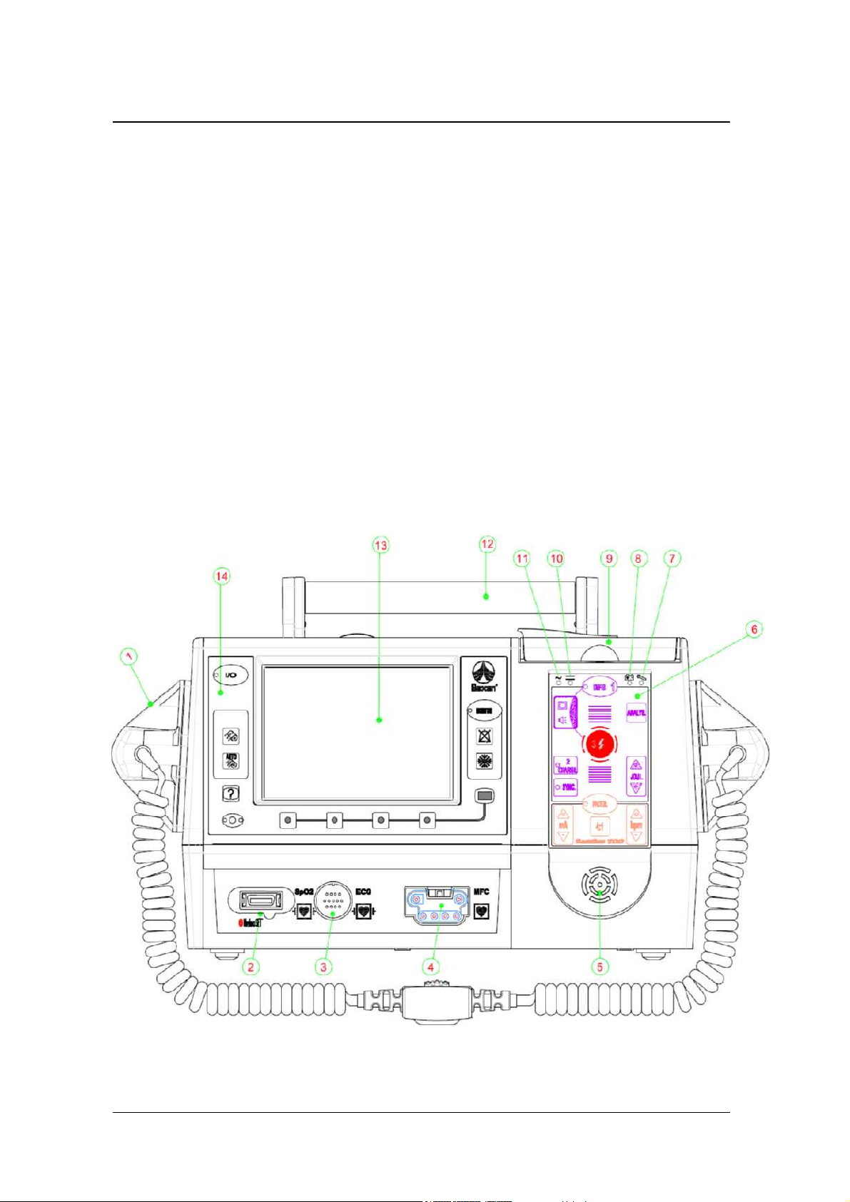
2.1.1 Front view
The elements and indicators that make up the front panel of the device are described below:
10

USER MANUAL DGH 700 B
NUMBER DESCRIPTION
1 REUSABLE EXTERNAL PADDLES
2
3
4
5
6
7
8
The PULSE OXIMETER extension cable CONNECTOR allows the
extension cable to be connected to the pulse oximetry sensor.
PATIENT CABLE CONNECTOR. It allows the patient cable to be
connected which can be 4, 5 or 10 leads.
MULTIFUNCTION CONNECTOR. It connects the reusable external
or internal paddles, and the single-use multifunction electrodes.
The high-fidelity SPEAKER system provides the sounds that indicate
an alarm, QRS detection, exceptional conditions that occur during the
utilization and also audible messages that guide the user during his
actions (Only for the devices that have the Semi-Automatic Defibrillator
option).
The FRONT PANEL which includes the activation keys for the
different operating modes.
MALFUNCTION INDICATOR. It is illuminated when the device
detects an error during any of the self-tests.
The BATTERY STATUS INDICATOR is an icon with a light. If this
indicator light is green it means the battery is charging and if it is red it indicates
LOW battery
9
10
11
12
13
14
Protective RECORDER COVER. The device recorder is located under
this protective cover.
DIRECT CURRENT INDICATOR. It indicates that the device is
connected to a DC external power supply source (car battery)
ALTERNATING CURRENT INDICATOR. It indicates that the
device is connected to an AC external power supply source (AC mains)
CARRYING HANDLE. This is a folding handle that allows simple
means of transport for the device.
Device SCREEN. This is a graphic display with 320 x 240 dot
resolution. The device has two types of optional screens: High-resolution
TFT and graphic LCD.
The FRONT PANEL includes the activation keys of the different
operating modes and keys that are common to all operating modes.
11
USER MANUAL DGH 700 B
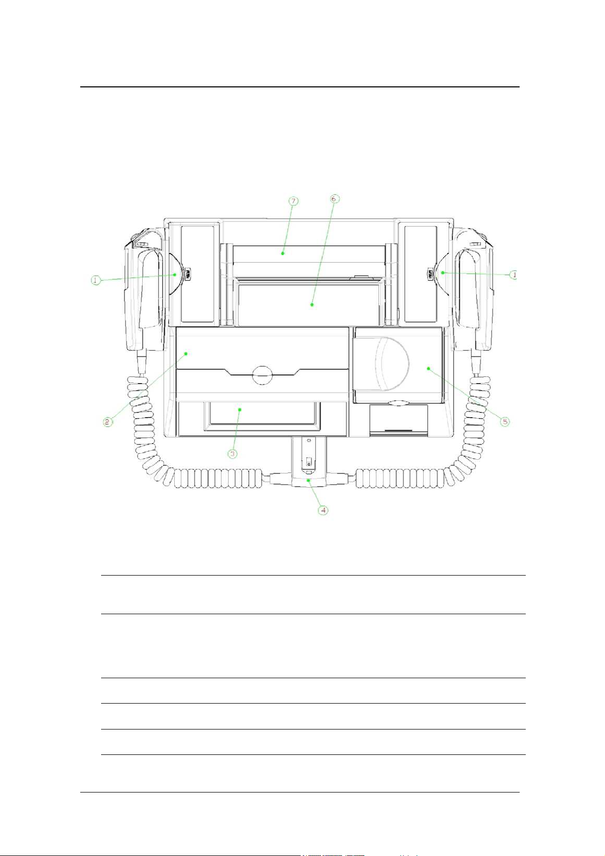
2.1.2 Overhead view
The elements that can be seen in the top part of the REANIBEX Serie 700:
12
NUMBER
DESCRIPTION
1
2
3
4
5
6
HOLDER of the reusable external paddles. To release the paddles, press
the holder and extract the paddles
Protective COVER of the COMPACT FLASH memory card. The
memory card holder is housed under this protective cover, Only the
devices that have the Semi-Automatic Defibrillator option have the
option of data recording in the Compact Flash.
Device SCREEN.
CONNECTOR for the Reusable external Paddles.
Protective RECORDER COVER.
Basic INSTRUCTIONS for use of the REANIBEX Serie 700.
USER MANUAL DGH 700 B
7 CARRYING HANDLE.
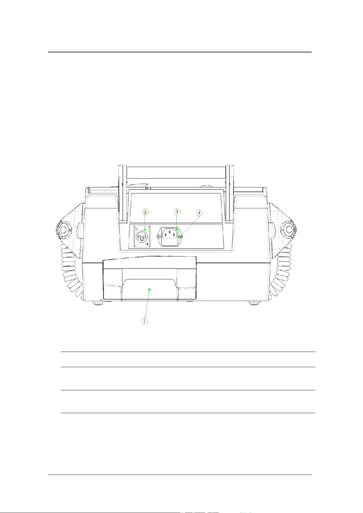
2.1.3 Rear view
The rear panel of the REANIBEX Serie 700 presents the following elements:
NUMBER
DESCRIPTION
1
2
3
4
BATTERY HOUSING. The place where the device’s battery is housed.
CAR BATTERY CONNECTOR. It enables the device to be connected
to a D.C. external power supply
AC POWER CONNECTOR. It allows the connection of the device to a
A.C. external power supply
EQUIPOTENTIAL CONDUCTOR. It provides an additional
connection to the ground connection of a building electrical installation.
13
USER MANUAL DGH 700 B
2.2 Front panel
This section describes the functions associated with each of the keys available on the front
panel. The different keys are grouped according to their operating mode.
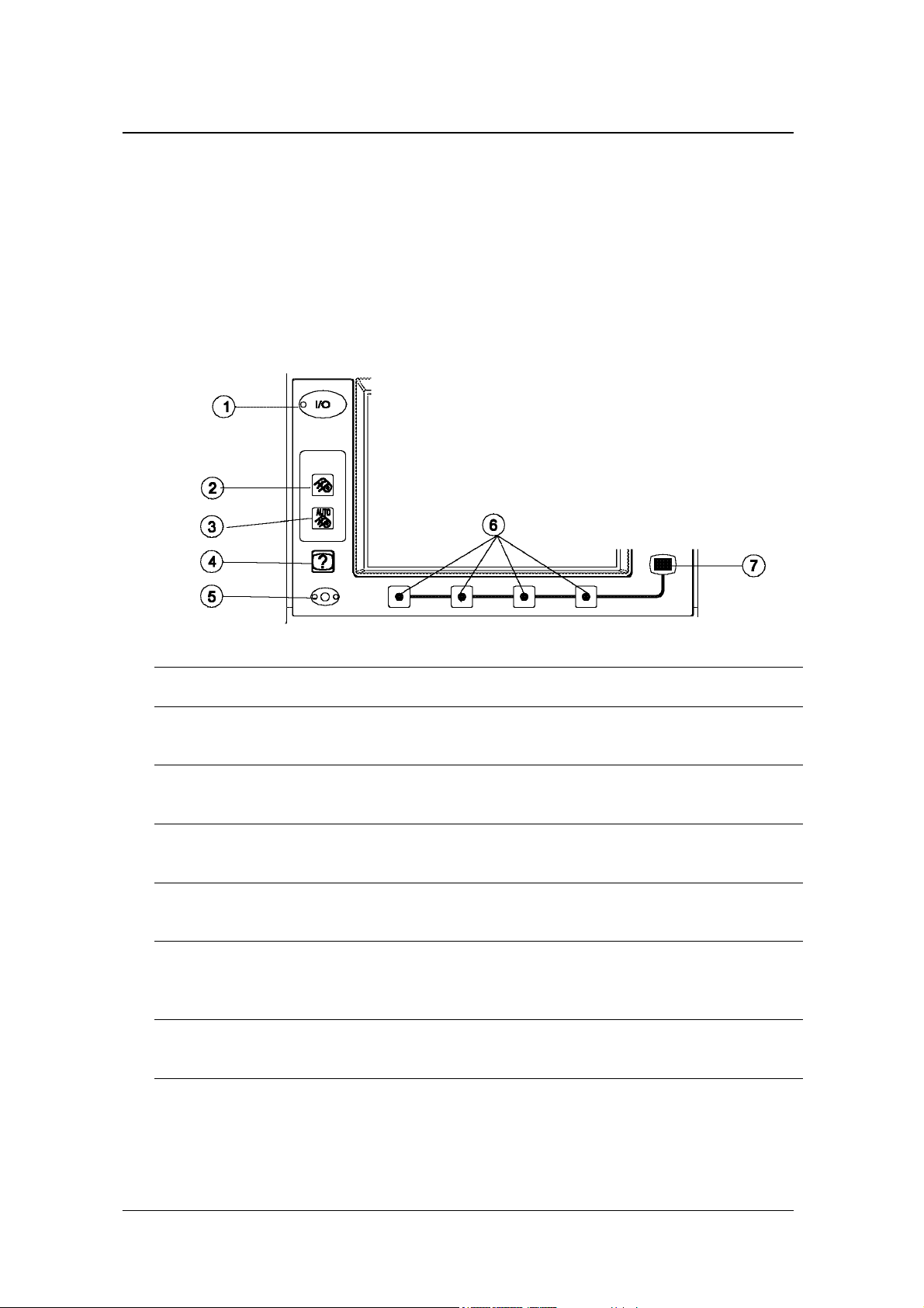
There are a series of keys which are common to all operating modes:
NUMBER DESCRIPTION
1
2
3
4
5
6
GREEN main on/off (I/O) key of the device. The indicator of this key is
illuminated when the device is switched on.
RECORDER start/stop key. It starts the recording of both the ECG
signal and the events which occurred during the operation.
AUTOMATIC RECORD key for all the leads. It allows all the leads to
be recorded depending upon the available patient cable.
EVENTS Key. It allows an event from a predetermined list to be
included in the actions.
MICROPHONE. It allows the audio recording of the surrounding
setting that unfolds during the utilization (only for devices that have this
option and are operating in Semi-Automatic Defibrillator mode)
FUNCTION KEYS. Their function changes depending upon the
operating mode
14
7
MENU Key. It allows access to the different available configuration
options in the various operating modes.

USER MANUAL DGH 700 B
2.2.1 Monitor Mode
The keys corresponding to the Monitor mode are described below:
NUMBER
DESCRIPTION
1
2
3
MONITOR mode access key. The indicator of this key is illuminated
when the device is operating in Monitor mode.
SUSPENDED SOUND ALARM Key. It allows sound alarm indicators
to be deactivated for a maximum of 2 minutes. If a new alarm occurs
while the sound alarm indicator is suspended, the sound alarm indicator
will be automatically reactivated.
FREEZE Key. It allows the ECG signal to be frozen on-screen. While
the signal is frozen, a small window appears at the top of the screen with
the temporary progression of the ECG signal.
2.2.2 Defibrillator Mode
The keys that correspond to the Defibrillator operating mode that are located on the front panel
of the device are:
15
USER MANUAL DGH 700 B
NUMBER
1
2
3
4
5
6
DESCRIPTION
DEFIBRILLATOR mode access key. The indicator of this key is
illuminated when the device is operating in Defibrillator mode.
Indicator to follow audible and visual instructions of the device when it
operates in Semi-Automatic Defibrillator mode.
CHARGE key for the selected energy level. The indicator of this key is
illuminated when the energy has finished charging. It can only be
activated in Manual Defibrillator mode.
ACTIVATION/DEACTIVATION key for SYNCHRONIZED shock.
When this option is active, the indicator of this key is illuminated. This
option is active only in Manual Defibrillator mode.
SELECT ENERGY Keys. They allow the energy level for discharge to
be selected. This key is active only in Manual Defibrillator mode.
SHOCK button. This button illuminates when the device is ready to
deliver a shock, and allows the defibrillation shock to be delivered to the
patient. It is only active when using single-use multifunction electrodes
or internal paddles.
7
ANALYSIS Key. It allows access to the Semi-Automatic Defibrillator
mode or to start an analysis during CPR. This key only appears in those
devices that have the Semi-Automatic Defibrillator option.
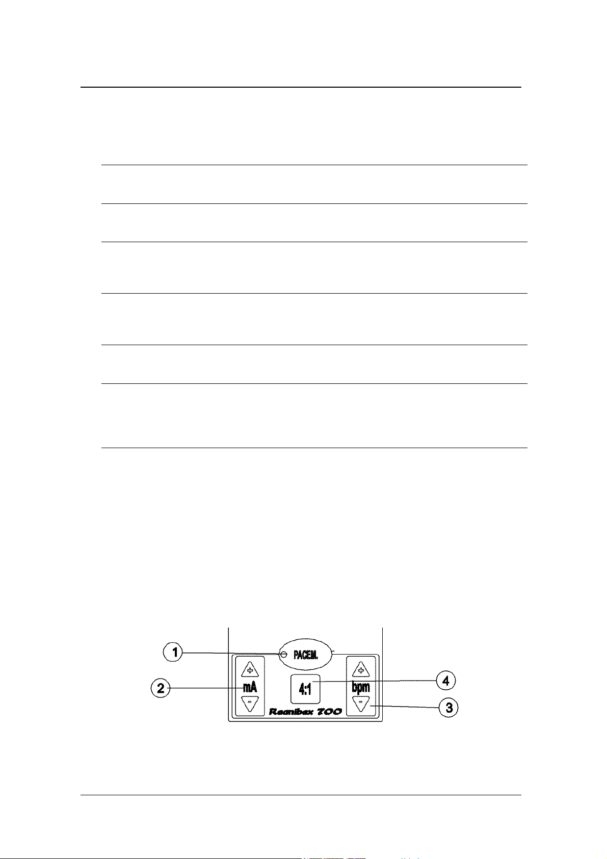
2.2.3 Pacemaker Mode (Optional)
The following keys located on the front panel of the REANIBEX Serie 700 allow it to operate
in the Pacemaker mode:
16
NUMBER
DESCRIPTION

USER MANUAL DGH 700 B
1
2
3
4
PACEMAKER mode access key. The indicator of this key is
illuminated when the device is operating in Pacemaker mode.
SELECT AMPLITUDE key to choose the correct amplitude for
pacemaker stimulation pulses
SELECT RATE key to choose the pacemaker stimulation rate
4:1 key. While holding this key pressed down, the pacemaker stimulation
rate is divided by 4 in order to be able to observe the intrinsic rhythm of
the patient.
2.3 Screen
The REANIBEX Serie 700 has a high-resolution LCD graphic display with 320x240 pixels (1/4
VGA) where both the ECG signal and the pleth waveform (SpO2) (optional) are displayed as
well as the information relating to the patient monitoring parameters and the status of the
device. The device comes with the option of a wide-angle TFT screen.
The screen of the device subdivides into three well differentiated parts:
1. Top part - Displays the operating parameters of the device (real-time clock, information
through the use of icons on battery status, equipment status, electrodes off, cancel sound
alarms, etc.), numerical values on the monitoring parameters (Heart Rate and SpO2%)
and icons which indicate exceptional operating conditions (recording errors, Compact
Flash Memory Card errors, etc.).
2. Middle part – Displays the biological signals. It can display a single ECG channel or
cascaded, or an ECG channel in conjunction with the pleth waveform for devices that
have this option available.
The ECG signal displayed on-screen is used to obtain the heart rate, to synchronize
energy shock delivery and to analyse heart rhythms in the Semi-Automatic Defibrillator
mode.
The lower section of this area also displays user guide messages when in Semi-
Automatic Defibrillator mode and informative messages for the rest of the modes.
3.
Lower part - Displays the connotation that is attributed to each of the function keys that
are located under the screen.
17

USER MANUAL DGH 700 B
SpO2
00:00:30
PADDLES x1
SpO2
SpO2(%)
PI: 12.7
PADDLES
CH2 : SpO2
SEN : 1 FILT : NO
2.4 Paddles, Electrodes and Patient Cables
For monitoring purposes, the REANIBEX Serie 700 can use patient's cable, reusable external or
internal paddles and single-use multifunction electrodes. For defibrillation, reusable external or
internal paddles and single-use multifunction electrodes can be used.
The device can be used with a 4, 5 or 10 lead patient cable. The device automatically detects
the type of cable connected which allows the different leads to be viewed.
The reusable external paddles have keys for energy selection and charging, for printing, and two
shock push buttons:
18

USER MANUAL DGH 700 B
NUMBER
The device can use two types of different single-use multifunction electrodes:
DESCRIPTION
1
2
3
4
5
SHOCK Push Button on the Sternum paddle. Operating in Manual
Defibrillator mode allows the shock to be delivered to the patient when
pushed simultaneously with the shock push button on the Apex paddle.
SELECT ENERGY Keys. They allow the energy discharge level to be
set when operating in Manual Defibrillator mode.
CHARGE Key. Operating in Manual Defibrillator mode allows the
energy discharge level to be charged.
SHOCK Push Button on the Apex paddle. Operating in Manual
Defibrillator mode allows the shock to be delivered to the patient when
pushed simultaneously with the shock push button on the Sternum
paddle.
PRINT Key. It allows both the biological signals and the events to be
recorded that occur with the device during the utilization.
19

USER MANUAL DGH 700 B
Single-use electrode-cables
WARNING: The device provides defibrillation-protected features only if the 4, 5 or 10
lead patient cable is used
2.5 Battery
The REANIBEX Serie 700 uses rechargeable high-capacity NiMH batteries that require
minimal maintenance.
The duration of these batteries depends upon how often they are used and their actual usage.
When used and maintained correctly the service life of the battery is 5 y
charge/shock cycles.
For more information about the battery consult section "13.6 Battery".
ears or 500
WARNING: Use only batteries supplied by OSATU or by its authorized distributors.
The use of another type of battery can cause device malfunction.
2.6 Events
The REANIBEX Serie 700 offers the user the option to include a series of predefined incidents
called EVENTS. To use this option, there is a key called EVENTS
20
on the front panel.

USER MANUAL DGH 700 B
This key is active in any of the operating modes and when it is pushed, a screen appears with
the following information:
The
table, whereas the
In the utilization performance report, the event will be displayed along with the time. In
addition, within the information recorded in the Compact Flash Memory Card, the event will be
recorded in the EGG signal recording as well as recording the 8 seconds prior to and following
this event.
NOTE: For more information about the meaning of the events, see "ANNEX “A6. Device
Events”
and keys allow the user to navigate the available options on the
key enters the event. To exit this option, use the key.
21

USER MANUAL DGH 700 B
2.7 Menu Options
Specific parameters can be configured during the utilization of the different REANIBEX Serie
700 operating modes. The MENU
The function keys located under the screen acquire a function that changes depending upon the
operating mode being used:
Monitor Mode
1.
The options that appear on the function keys for this mode allow changes to be made in
the alarm settings, the recording options and the user interface.
can also be viewed.
key on the front panel allows access to the options.
The report and trends
ALARMS REPOR RECOR INTERF
2. Manual Defibrillator Mode
The options that appear on the function keys for this mode allow changes to be made in
the alarm settings, the recording options, the user interface:
3. Semi-Automatic Defibrillator and Pacemaker Modes
The options that appear for these modes only allow changes to be made in the recording
and user interface options:
2.7.1 Alarms Menu
By pressing the
available in the device:
22
ALARMS
key, the screen allows the user to set the different alarm limits

USER MANUAL DGH 700 B
For more information about changing the alarm settings, consult section "4.6 Alarms".
2.7.2 Report Menu
Pressing the
REPOR
key accesses the screen that displays the utilization performance report.
23

USER MANUAL DGH 700 B
SpO2
00:00:30
EVENT HH:MM
Switch-ON 14:24
- -MANUAL DEF. 14:24
Alarms Si 14:24
HR max 140 14:24
HR min 30 14:24
SpO2 max 99 14:24
SpO2 min 80 14:24
VT-VF No 14:24
No Paddles 14:24
PatCab Conec 10 14:24
SpO2(%)
PI: 12.7
Pag: 1/1
- -MONITOR 14:26
… Amioradone 14:28
- -PACEMARKER 14:35
Mode Fixed 14:35
Amplitude 60 14:35
Frecuency 60 14:35
- -MONITOR 16:10
TREND
In the top part of the screen, the number of pages (screens) in the report is displayed. The
different pages can be viewed using the
From this screen, pressing the
TREND
key gives access to the graph displaying the Heart
Rate (HR) and pulse oximetry (SpO2%) trends (for devices with this option).
and keys.
24

USER MANUAL DGH 700 B
Within the trends screen, if the
screen from start-up up to the present. In the top part, the maximum and minimum HR values
HR
key is pressed the Heart Rate trend will appear on-
are displayed that were recorded during this interval, along with the time they occurred.
For devices that have the pulse oximetry option, when the
screen appears but it displays the recorded pulse oximetry (% SpO2) values.
While viewing both, the report and the trends, the information will be continuously updated, in
such a way that if an event/incidence occurs or if new HR and % SpO2 values are recorded, the
information will be updated.
Cancel
The
key will eliminate the trends and the utilization performance report.
SpO2
key is pressed, a similar
2.7.3 Recorder Menu
By pressing the
RECOR
key, the function keys located below the screen allow changes to be
made in the recorder parameters:
AUTO : NO DELAY:NO SPEED:10
AUTO:NO
The
the
parameters.
To exit this menu and return to the previous menu, use the
For more information about the recorder, consult Section "11.5.1.5 Recorder”
DELAY:NO
SPEED:10
key allows the user to configure the automatic printing mode of the recorder,
key configures whether or not delayed printing is required and the
key selects the printing speed. Press the corresponding key to change the
key.
25

USER MANUAL DGH 700 B
2.7.4 Interface Menu
When the
INTERF
key is pressed, changes can be made to the settings for the user interface:
CON 13:16 VOL 4:8 BEEP
CON 13:16
The
VOL 4:8
for devices that have this option). In both cases the first number that appears on this key
indicates the level selected whereas the second number indicates the levels available. Press the
key until obtaining the desired parameter level.
The
disabled, the
To exit this menu and return to the previous menu, use the key.
BEEP
key allows the contrast settings to be set for the device’s screen. By using the
key, both the volume and the beeps emitted for messages can be adjusted (only
key enables the QRS beep to be activated/deactivated. When the beep is
icon appears in the top of the screen to confirm the deactivation.
26

USER MANUAL DGH 700 B
3. Installation of the Device
3.1 General
Before using the REANIBEX Serie 700, make sure that the device is ready for use. To do so,
perform the following checks:
• Make sure that the device is in perfect condition. Check that both the device and its
accessories and cables do not show any signs of damage, and that they are in good condition.
• Check the battery status. Turn the device on and check the battery status indicator located in
the upper part of the device screen, as well as the battery status indicator located in the front
cover of the device. If the indicator remains illuminated and red, it indicates that the battery
charge is low.
WARNING: Use only batteries supplied by OSATU or by its authorized distributors. The
use of another type of battery can cause device malfunction.
• Make sure that the defibrillation and the monitoring electrodes are stored under perfect
conditions. Check their expiry date as well.
WARNING: Follow the instructions given on the labels of the defibrillation and
monitoring electrodes carefully.
WARNING: Both the defibrillation electrodes and the monitoring electrodes must be used
before the expiry date indicated on their label. If the electrodes have dried up or are
damaged they can cause electric arcs and burns during their use.
WARNING: Dispose of both the defibrillation and monitoring electrodes once they have
been used.
• Always keep the following replacement items at hand:
- A spare battery, in a good state of maintenance.
- Spare defibrillation and monitoring electrodes.
- Accessories for cleaning and shaving the areas where the electrodes are to be
positioned on the patient, if necessary.
27

USER MANUAL DGH 700 B
3.2 Cables
The REANIBEX Serie 700 has the option of using the 4, 5 and 10 lead patient cable for
monitoring the ECG signal which automatically detects the connected cable. The ECG signal
can also be monitored by using reusable external and internal paddles or single-use
multifunction electrodes.
Connection of the patient cable is carried out as is indicated in the following figure:
For defibrillation, the device provides the option of connecting reusable internal or external
paddles or single-use multifunction electrodes. All of them are connected in the multifunction
connector (MFC) located on the front panel of the device:
The device also has the option of a pulse oximetry module. The connection of this cable to the
device is made via the connector on the front panel of the device as indicated in the figure:
28

USER MANUAL DGH 700 B
3.3 Battery
The REANIBEX Serie 700 uses high-capacity rechargeable NiMH batteries that require
minimal maintenance. The battery compartment is located in the rear of the device so that
access is rapid and simple.
To install the battery, align it with the compartment located in the rear of the device and
introduce the battery into the device until a “click” is heard which indicates that the battery has
been correctly inserted.
When the battery is installed in the device and connected to an external power supply (AC mains
or car battery), the device continuously charges the battery, using an internal charger.
29

USER MANUAL DGH 700 B
To extract the battery, pull the device’s battery lock latch (black-coloured) upwards and holding
it in this position, extract the battery from its compartment.
3.4 Recorder (Optional)
The REANIBEX Serie 700 recorder is located in its upper part. To install paper in the recorder,
perform the following steps:
1. Open the cover of the device where the recorder is located
2. Open the door of the recorder pressing its safety catch as shown in the figure.
3. If there is an empty roll of paper or a roll that needs to be replaced, remove it by pulling
it upwards.
4. Insert the new roll of paper, so that the end of the paper is towards the right side and the
grid pattern is downwards.
5. Pull the end of the paper out a few centimeters in such a way that, on closing the door of
the recorder and the cover of the device, the paper projects towards the left side of the
device.
3.5 Compact Flash Memory Card (Optional)
The REANIBEX Serie 700 offers the option of a Compact Flash memory card, in which
information is stored relating to the actions performed with the device.
30

USER MANUAL DGH 700 B
The insertion and removal of this Compact card must always be carried out with the device
switched off in order to avoid loss of information.
To insert the memory card in the device:
1- After switching the device off, open the top cover of the device located just above
its screen.
2- Insert the memory card with the portion that contains the name and indicating arrow
towards the front. The arrow must point downwards.
3- Press until the mechanism located on the right side of the card projects from the
device.
4- Close the top cover of the device.
To remove the card from the device:
1- After switching the device off, open the top cover of the device located just above
the screen.
2- Press the mechanism located to the right of the Compact Flash card until the latter
projects from the device.
3- Remove the card and close the cover of the device.
WARNING: Insert and remove the Compact Flash memory card only when the
device is switched off. If the Compact Flash card is inserted with the device switched
on, the data will not be recorded, whereas if the Compact Flash card is removed with
the device switched on, the information about the current utilization will be lost.
31

USER MANUAL DGH 700 B
Blank sheet
32

USER MANUAL DGH 700 B
4. Monitoring
4.1 Description
In this section, the basic functions of the REANIBEX Serie 700, operating in Monitor mode, are
described.
The REANIBEX Serie 700 can be used for monitoring the ECG signal and arrhythmias using
the 4, 5 or 10 lead patient cable, the external reusable paddles or the single-use multifunction
electrodes.
MONITOR
To access the Monitor mode, press the
key on the front panel. The key indicator will
be illuminated, indicating that it is in Monitor mode. The screen that appears when this mode is
accessed is as follows:
SpO2
00:00:30
PADDLES x1
PADDLES CH2 : - -
SpO2(%)
PI: 12.7
SEN : 1
FILT : NO
When the patient cable and the paddles or the single-use multifunction electrodes are connected
to the device, the device allows a patient cable lead or a paddle lead or multifunction single-use
electrodes lead to be selected.
33

USER MANUAL DGH 700 B
4.2 Warnings
WARNING: Possible incorrect interpretation of the ECG data. The monitor screen is
indicated solely for the identification of the basic ECG rhythm since it does not have
the resolution required to make a diagnosis. To make any diagnosis or interpretation,
print out the ECG signal.
WARNING: The REANIBEX Serie 700 does not have the capacity to reject internal
pacemaker pulses. The device could detect the internal pacemaker pulses as QRS
complexes which results in an indication of an incorrect heart rate. Do not rely on the
heart rate indicator displayed by the device with patients who have an internal
pacemaker.
WARNING: Make sure that when connecting and disconnecting the electrodes from
the patient’s skin, they do not come in contact with any conducting materials.
4.3 ECG Monitoring Procedure
The monitoring function of the REANIBEX Serie 700 can be performed using either, the patient
cable, internal or external reusable paddles and single-use multifunction electrodes.
The REANIBEX Serie 700 automatically detects the type of patient cable that has been
connected (4, 5, or 10 lead). In addition, it is able to distinguish if in the multifunction connector
(MFC) is connected to the single-use multifunction electrodes and external or internal paddles.
4.3.1 Use of paddles and single-use multifunction electrodes
To monitor the ECG using paddles or single-use multifunction electrodes, follow the steps
below:
34

USER MANUAL DGH 700 B
1. Connect the paddles or electrode cable to the multifunction connector (MFC) of the
REANIBEX Serie 700 as shown in the following figures:
2. Prep the patient’s skin in the places where it will be necessary to connect the electrodes
or the paddles:
− Remove chest hair from the patient if necessary. Avoid scraping or cutting the
patient’s skin. Avoid placing the electrodes or the paddles on broken or irritated
skin.
− Thoroughly clean and dry the patient’s skin. Do not ever use either pure alcohol
or ether to clean the patient’s skin, since these products increase skin resistance.
3. Position the electrodes or the paddles in the anterior-lateral position.
When using single-use multifunction electrodes, make sure that the seal on the single-
use multifunction electrode packet is perfectly intact and that the expiry date is still
valid.
4. Select the PADDLES lead for viewing the signal obtained using the single-use
electrodes or paddles.
Take into account the following special considerations when placing both the electrodes and the
paddles:
− Obese patients or patients with large breasts. Apply the electrodes or the paddles on
a flat surface of the torso.
− Thin patients. Press the electrodes on the torso following the contour of the ribs to
avoid air cavities.
− Patients with implanted pacemakers. Position the electrodes or the defibrillation
paddles at least 10 cm from the generator and continue with the same procedure
protocol as for any other patient with a cardiac arrest.
− Patients with implanted defibrillators. Position the electrodes or the defibrillation
paddles at least 12-15 cm from the generator, and continue with the same procedure
protocol as for any other patient with a cardiac arrest.
35

USER MANUAL DGH 700 B
WARNING: If monitoring is carried out for prolonged periods of time, it may be necessary to
periodically change the single-use multifunction electrodes. Consult the documentation on
single-use multifunction electrodes in order to change them.
4.3.2 Use of patient cable
The monitoring of the ECG signal, using the patient cable can be performed using a 4, 5 and 10
lead cable. Follow the steps below to monitor the ECG signal using the patient cable.
1. Connect the patient cable to the connector of the REANIBEX Serie 700 as shown in the
following figure.
2. Prep the patient's skin in the places where the monitoring electrodes will be positioned.
− Remove chest hair from the patient if necessary. Avoid scraping or cutting the
patient’s skin. Avoid placing the electrodes or the paddles on broken or irritated
skin.
− Thoroughly clean and dry the patient’s skin. Do not ever use either pure alcohol
or ether to clean the patient’s skin, since these products increase skin resistance.
3. Position the monitoring electrodes and connect them to the patient cable. Make sure that
the seal of the monitoring electrode pack is perfectly intact and that the expiry date is
still valid.
4. Select the desired lead that will be viewed.
WARNING: If monitoring is carried out for prolonged periods of time it may be necessary to
periodically change the monitoring electrodes. Consult the documentation on monitoring
electrodes in order to change them.
36

USER MANUAL DGH 700 B
Take into account the following guidelines during the use of the electrosurgical unit to minimize
interference from the electrosurgical equipment and to provide maximum security for the patient
and the user:
• Keep all patient monitoring cables off the ground and away from blades and
electrosurgical unit return cables.
• Make sure that the grounding pad of the electrosurgical unit is properly placed on the
patient.
WARNING: To prevent burns due to the electrosurgical unit in monitoring areas, make sure
that the electrosurgical unit’s return circuit is properly connected so that the return pathways
cannot travel through the monitoring electrodes.
4.3.3 Positioning the monitoring electrodes
For the correct positioning of the monitoring electrodes, the following figure should be taken
into account which shows the positioning of all the monitoring electrodes depending upon the
patient cable available in the device.
If monitoring is carried out with six precordial leads, it is important to locate the fourth
intercostal space since this landmark serves as reference for positioning the rest of the precordial
leads. To locate this landmark:
1. Place the finger in the depression of the superior part of the sternum.
2. Go downwards until locating a small bony protuberance (Angle of Louis), which is
where the manubrium joins the body of the Sternum.
3. Locate the second intercostal space on the right side of the patient just below the
angle of Louis.
4. Move downwards another two intercostal spaces until locating the fourth, which is
the position of the V1/C1 lead.
37

USER MANUAL DGH 700 B
• 4 Lead Patient Cable
1- Position of RA/R (White/Red) - Near the right shoulder and below the clavicle.
2- Position of LA/L (Black/Yellow) - Near the left shoulder and below the clavicle.
3- Position of LL/F (Red/Green) - On the lower left part of the abdomen.
4- Position of RL/N (Green/Black) - On the lower right part of the abdomen.
• 5 Lead Patient Cable
1- Position of RA/R (White/Red) - Near the right shoulder and below the clavicle.
2- Position of LA/L (Black/Yellow) - Near the left shoulder and below the clavicle.
3- Position of LL/F (Red/Green) - On the lower left part of the abdomen.
4- Position of RL/N (Green/Black) - On the lower right part of the abdomen
5- Position of V/C (Brown/White) - On the thorax, depending upon the required lead.
• 10 Lead Patient Cable
1- Position of RA/R (White/Red) - Near the right shoulder and below the clavicle or
on the right arm.
38

USER MANUAL DGH 700 B
2- Position of LA/L (Black/Yellow) - Near the left shoulder and below the clavicle or
on the left arm.
3- Position of LL/F (Red/Green) - On the lower left part of the abdomen or on the left
leg.
4- Position of RL/N (Green/Black) - On the lower right part of the abdomen or on the
right leg.
5- Position of V1/C1 - The fourth intercostal space, on the external right edge.
6- Position of V2/C2 - The fourth intercostal space, on the external left edge.
7- Position of V3/C3 - At half the distance between V2 and V4.
8- Position of V4/C4 - Fifth intercostal space, on the left mid clavicular line.
9- Position of V5/C5 - At the same level as V4 on the anterior axillary line.
10- Position of V6/C6 - At the same level as V4 on the left mid axillary line.
4.4 Selecting the size and the lead
In order to accurately detect the potential patient pathologies, it is important to choose the
appropriate lead and its size.
The number of leads that can be viewed depends upon the type of patient cable connected. The
leads that can be viewed for the different patient cables are indicated below.
− 4 lead patient cable: I, II , III, aVR, aVL and aVF
− 5 lead patient cable: I, II, III, aVR, aVL, aVF and V
− 10 lead patient cable: I, II, III, aVR, aVL, aVF, V1, V2, V3, V4, V5 and V6
The selection of the lead to be viewed is made by using the
screen of the device. The selected lead is viewed both on-screen beside the waveform, and in the
key that allows the selection of the lead. To select the required lead, press the key until obtaining
PADDLES
key located below the
the required lead.
It is important to select the proper lead to monitor the ECG as the ECG signal displayed on-
screen is used to obtain the heart rate, to synchronize energy shock delivery and to analyse heart
rhythms in the Semi-Automatic Defibrillator mode. It is advisable to select a lead with the
following characteristics:
39

USER MANUAL DGH 700 B
- High and narrow QRS complex (>0.5mV recommended)
- The R wave must be above or below the baseline (but not biphasic)
- The height of the P wave must be inferior to 1/5 of the height of the R wave.
- The height of the T wave must be inferior to 1/3 of the height of the R wave.
The device also detects if any of the leads that form a part of the patient cable become detached
or are improperly connected. When this occurs, the
the device's screen. Depending upon which lead is off or improperly connected, the device may
be able to allow the user to view a limited number of other leads. When it is not possible to view
a lead and the user selects this lead, a broken line will be displayed on screen in the base line of
the signal.
Changing the size (sensitivity) of the lead being viewed is performed by using the
key located under the screen of the device. The sensitivity values available in the device are 0.5,
1, 2 and 4 cm/mV. To select the required sensitivity, press the key until obtaining the required
size. The sensitivity selected appears both in the upper part of the screen beside the waveform,
and in the key that allows the size to be selected.
The REANIBEX Serie 700 device allows the ECG signal to be viewed in cascade, that is, when
this option is selected the lead will appear on-screen in 2 channels (9 seconds of the lead being
viewed).
icon will appear in the upper part of
SEN: 1
For those devices that offer the pulse oximeter option, in addition to the ECG signal in cascade,
the pleth waveform (SpO2 curve) can be viewed in the second channel.
The selection of the information to be viewed in the second channel is made by using the
CH2: ECG
−
−
−
40
key located under the screen. The options available for this key are:
CH2: - -
CH2: ECG
CH2: SpO2
be viewed in the second channel.
Only one ECG channel can be viewed on the device’s screen
The ECG signal in cascade is viewed
For devices that offer the pulse oximetry option, the pleth waveform can

USER MANUAL DGH 700 B
4.5 Selecting the Filter
The selection of the filter for the ECG signal is made by using the fourth key located under the
screen. The options available for this key are:
−
active, it eliminates potential disturbances in the ECG signal originating from muscle
activity.
−
filter is NOT selected, the device provides the full bandwidth.
The changes made by using this key when activated will apply to both the ECG signal on the
screen and the printed signal from the recorder. However, screen limitations hinder the quality
of the ECG that appears on-screen which is essential in making an accurate diagnosis.
In the Configuration of the device, the muscle artifact filter can be applied to the signal by
default if this option is selected. See Section
Muscle artifact filter: 0.67-40 Hz (only in recorder) When this filter is
Diagnostic: 0.05-150 Hz (only in recorder) Whenever the muscle artifact
11.5.1.1.
4.6 Alarms
The REANIBEX Serie 700 allows alarm conditions to be detected in the different parameters
monitored, according to a number of criteria set by the user. All the biological parameters
alarms are high priority alarms.
Access to the screen that allows the alarm limits to be changed is obtained by first pressing the
menu key on the front panel, and then pressing the
device’s screen. The screen that appears when this mode is accessed is as follows:
ALARMS
key located below the
41

USER MANUAL DGH 700 B
SpO2(%)
00:00:30
SpO2
PI: 12.7
Maximum HR limit …....................... 150 ppm
Minumum HR limit …......................... 30 ppm
Maximun SpO2 limit ............................. 99 %
Minimum SpO2 limit ............................. 80 %
SpO2 sensitivity ................................ Normal
VT/VF Alarm........................................... YES
SELEC
There are 5 alarm limits available that can be set by the user, as well as the sensitivity for the
pulsioximeter:
− Maximum HR Limit. A higher Heart Rate limit can be set and when this limit is
exceeded, the device will display a visual and acoustic indicator. This parameter can
vary from 30 to 300 bpm and it changes in increments of 1 bpm.
− Minimum HR Limit. A lower Heart Rate limit can be set and when the patient's Heart
Rate is under the set rate, the device will display a visual and acoustic indicator. This
parameter can vary from 30 to 300 bpm and it changes in increments of 1 bpm. Its value
can never be greater than the upper HR limit.
− Maximum SpO2 Limit. Only for devices that have pulse oximeter. It allows a
saturation limit to be set and when this limit is exceeded, the device will display a visual
and acoustic indicator. This parameter can vary from 85 to 100 % in increments of 1%.
− Minimum SpO2 Limit. Only for devices that have pulse oximeter. A saturation limit
can be set and when the patient's SpO2 is under the set limit, the device will display a
visual and acoustic indicator. This parameter can vary from 85 to 100 % in increments
of 1%. Its value can never be greater than the upper SpO2 limit.
42

USER MANUAL DGH 700 B
− SpO2 Sensitivity. Only for devices that have pulse oximeter. It allows a sensitivity
mode to be set. This parameter can take tree different values: Normal, Maximum,
APOD (Adaptive Prove Off Detection).
− VT/VF Alarm. Only for devices that have the Semi-Automatic Defibrillator option. It
allows the device to be configured so that it analyses the ECG signal and emits a
warning if it detects potential Ventricular Fibrillation or rapid Ventricular Tachycardia.
Changes in the alarms are carried out by using the keys located below the screen. By using the
SELECT
meanwhile the
key allows the user to return to the monitoring screen, performing procedures employed as well
as the setting changes made to the alarms.
Changes in the alarms are only allowed in the MONITOR and MANUAL DEFIBRILLATOR
modes, and in the latter, only when the device is not charging energy or in standby for delivering
a shock.
When the device is switched on, the different alarms limits adopted depend upon the
configuration of the device:
key, the different alarms are selected (the selected alarm is shown in reverse video),
and keys change the minimum values. The
- If the configuration is set so that the alarm limits are FIXED, when the device is
switched on, the values indicated in Configuration are always adopted by default.
- In all other cases, the device is configured for alarm limits that are
PROGRAMABLE and it will record the limit values that were configured when the
device was switched off and the next time it is switched on, it will adopted these
values as start-up limits.
WARNING: There is a potential risk when using different alarm limits for the same or
similar equipment in any area such as intensive care unit or operating room for heart
surgery.
WARNING: Before each use, confirm that the alarm limits are appropriate for the patient
being monitored. It must also be taken into account whether an operator will continually
monitor the patient.
43

USER MANUAL DGH 700 B
WARNING: Do not adjust the alarm limits to such extreme values that the alarm system is
rendered useless.
4.6.1 HR and SpO2 Alarms
When an alarm condition occurs, either HR or SpO2 (only for devices that have the pulse
oximeter option), the device will give both a visual (blinking of the indicator for the parameter
that triggers the alarm) and acoustic indication.
The acoustic indication is automatically deactivated if the alarm condition disappears. During
the alarm condition, the user can deactivate the acoustic indicator using the
on the front panel. This key will remain deactivated as long as no other alarm condition is
present. When the acoustic indicator is suspended, the device’s screen will show the same icon
that appears on the front panel key which will automatically disappear when the alarm condition
disappears.
Once the acoustic indicator has been deactivated, whether automatically or by an action on the
part of the user, by pressing the key on the front panel, it will automatically reactivate after 2
minutes if the alarm condition is still present. If the indicator is suspended and an alarm occurs,
it will visually and acoustically indicate the new alarm condition that developed.
The visual alarm indicator consists of the on-screen blinking of the parameter that triggered the
alarm (HR and/or SpO2%). This on-screen indicator remains active for the duration of the alarm
condition, meaning, until the parameter that triggered the alarm falls within the selected limits.
key located
4.6.2 VT/VF Alarm
The VT/VF alarm is only available for those devices that have the Semi-Automatic Defibrillator
option (ECG signal analysis capacity). This alarm is only active in the MONITOR and
MANUAL DEFIBRILLATOR modes.
By activating this alarm, on-screen viewing and recorder will be limited to Lead II or the
PADDLES. The VT/VF alarm will not be active, meaning the signal is not analyzed, if the
44

USER MANUAL DGH 700 B
paddle lead, with reusable external or internal paddles has been selected and there is no patient
cable. If the user has connected internal or external reusable paddles and the patient cable is
connected, only Lead II can be analyzed.
If both the patient cable and the single-use multifunction electrodes are connected, and the user
changes from the paddle lead to Lead II, or vice versa, signal analysis will begin once again.
The VT/VF alarm will be suspended in Manual Defibrillator mode if the device is charging,
once it is charged, when reusable internal or external paddles are being connected and when it is
changing over to Pacemaker mode (only for devices with this option).
By switching the device on, the alarm value will depend upon the configuration option which
can be changed afterwards by the user.
When this alarm is active and is analysing the signal, the
of the screen.
If the VT/VF alarm is triggered, meaning that potential Ventricular Fibrillation or rapid
Ventricular Tachycardia is detected, the message “EXAMINE PATIENT” is periodically
emitted both on-screen and audibly (optional configuration), and the screen icon related to this
alarm starts to blink.
When there is an error in the Semi-Automatic Defibrillator operating mode, the VT/VF alarm
will not be operative, and therefore it cannot be selected by using the screen that allows
modification of the alarms.
icon appears in the upper part
45

USER MANUAL DGH 700 B
5. Manual Defibrillation
5.1 Description
In this section, the basic functions of the REANIBEX Serie 700, operating in MANUAL
DEFIBRILLATOR mode, are described.
In the MANUAL DEFIBRILLATOR mode, it is the user that must evaluate the ECG signal,
decide if it is necessary to deliver a defibrillation shock, select the appropriate energy level,
charge this energy and carry out the shock. In this operating mode, the device will not give any
indication whatsoever of whether or not it is advisable to deliver a shock.
Devices that have the Semi-Automatic Defibrillator option allow the device to be configured so
that in the Manual Defibrillator mode specific warning messages are audibly emitted.
In this operating mode, the alarms are available for modification at all times except when energy
is being charged or it is in standby for delivering a shock.
In Manual Defibrillator Mode, ECG monitoring can also be carried out using the 4, 5 and 10
lead patient cable. The device detects the type of patient cable connected allowing all available
leads to be monitored.
For those devices that have the pulse oximeter option, the % of SpO2 can be monitored and the
pleth waveform (optional), if required. This latter curve will always be displayed when selected
and up to the time any key in the Defibrillator mode is activated, at which time, it disappears in
order to display the standard messages of the mode that are already considered a priority.
Access to the Manual Defibrillator mode is carried out in 2 ways:
1. Once the device has been switched on, press the
panel. Either the device was configured to switch on in Manual Defibrillator mode or if
after operating in Manual Defibrillator mode, it switches to another operating mode and
returns to Defibrillator mode (the device’s memory recalls if it was in Manual or Semi-
Automatic mode).
46
DEFIB.
1
key located on the front

USER MANUAL DGH 700 B
2. Press the
Semi-Automatic mode (Only for devices with this option). Access to the Manual
MANUAL
key located under the screen when the device is operating in
Defibrillator mode will depend upon the configuration of the device.
− Free access. The Manual Defibrillator mode is directly accessed without any
type of restriction.
− Access using a Passcode. Access to the Manual Defibrillator mode requires an
attributed passcode:
Using the keys located below the screen the access passcode to the Manual
Defibrillator mode can be entered.
Once the passcode has been correctly entered, it is not necessary to enter it
again whenever a change is made from Semi-Automatic Defibrillator mode to
Manual Defibrillator mode.
− Restricted Access. Access to Manual Defibrillator mode is not permitted and
therefore the aforementioned key does not appear in the lower part of the
screen.
DEFIB.
In any case the indicator located beside the
indicating that it is in Defibrillator mode.
In the lower part of the screen, which appears after accessing this mode, an energy indicator for
the selected energy level is always displayed:
1
key must be illuminated,
47

USER MANUAL DGH 700 B
5.2 Warnings
WARNING: Eletrical shock hazard. The defibrillator can deliver up to 200 Joules of
electrical energy. When the shock is being carried out, make sure that no one touches the
surface of the paddles or the single-use multifunction electrodes.
WARNING: Eletrical shock hazard. Make sure that during defibrillation everyone stands
clear and no one touches the patient, the bed or any conductive material that is in contact
with the patient. The defibrillation current can partially shock through this person, causing
injury to the user and to persons close to the device.
WARNING: Eletrical shock hazard. If charged energy needs to be eliminated, do not
discharge the defibrillator in the air. To dispose of the charged energy, change the energy
level, change over to another operating mode or switch the defibrillator off.
WARNING: Burn and fire hazard and unsuccessful energy delivery. Do not discharge the
reusable paddles on the single-use multifunction electrodes or on the monitoring electrodes.
The reusable paddles or single-use multifunction electrodes must not touch each other or
come into contact with the monitoring electrodes, leadwires, dressings, etc. These contacts
48

USER MANUAL DGH 700 B
could result in electric arcs which cause skin burns to the patient and deviate a portion of the
defibrillation energy.
WARNING: Burn hazard to the skin of the patient. Air pockets formed between the
defibrillation electrodes and the skin of the patient can cause burns during defibrillation.
Ensure that the defibrillation electrodes are perfectly adhered to the skin of the patient. Once
good skin contact is established, if the position of the electrodes must be changed, remove the
electrodes and replace them with new ones.
WARNING: Burn hazard to the skin of the patient and unsuccessful energy delivery. Very
dry or damaged electrodes can cause an electrical arc during shock resulting in burns to the
skin of the patient.
WARNING: Burn hazard to the skin of the patient and unsuccessful energy delivery. Do not
use the electrodes after their expiry date, not even if they have been opened. Replace the
electrodes after every 50 shocks.
WARNING: Burn hazard to the skin of the patient and unsuccessful energy delivery. The
conductive gel in the handles of the paddles can cause the energy shock to pass through the
user during defibrillation. Clean the surface of the paddles and their handles thoroughly
after performing defibrillation.
WARNING: Burn hazard to the skin of the patient and unsuccessful energy delivery. Do not
allow the conductive gel to form a path on the patient’s skin between the two defibrillation
paddles, or between the single-use multifunction electrodes. This could cause an electrical
arc between the paddles or the electrodes resulting in burns to the skin of the patient and a
deviation of a portion of the defibrillation energy.
WARNING: Burn hazard to the skin of the patient and unsuccessful energy delivery. The
leads of the patient cable could prevent the correct positioning of the electrodes of the
defibrillation electrodes. Before performing any defibrillation, remove and disconnect all
those elements that could interfere with it.
WARNING: Danger of potential interference with implanted electrical devices. Defibrillation
can cause malfunction in the implanted devices. Whenever possible, position the paddles or
the electrodes away from the implanted devices. As soon as defibrillation is concluded, check
that the implanted device is functioning correctly.
49

USER MANUAL DGH 700 B
WARNING: Potential defibrillator shutdown. Defibrillator energy charging places a great
demand for battery current. When the device is operating solely on batteries, and at the same
time, the device is also charging the defibrillator, it can shutdown without any apparent
indicator that the battery is low. If this occurs, replace the battery with a fully charged spare
battery or connect the device to an external power supply.
WARNING: Potential equipment hazard. Before using the defibrillator, disconnect the
patient from all equipment that is not defibrillator-protected.
5.3 Preparation for Defibrillation
The first step in Manual Defibrillation consists of connecting the proper defibrillation cable to the
device, placing the paddles or electrodes as described in the following sections.
Take into account the following special considerations when placing both the electrodes and the
reusable external paddles:
− Obese patients or patients with large breasts. Apply the electrodes or the paddles on
a flat surface of the torso.
− Thin patients. Press the electrodes on the torso following the contour of the ribs to
avoid air cavities.
− Patients with implanted pacemakers. Position the electrodes or the defibrillation
paddles at least 10 cm from the generator and continue with the same procedure
protocol as for any other patient with a cardiac arrest.
− Patients with implanted defibrillators. Position the electrodes or the defibrillation
paddles at least 12-15 cm from the generator, and continue with the same procedure
50
protocol as for any other patient with a cardiac arrest.

USER MANUAL DGH 700 B
5.3.1 Utilization of Multifunction Single-Use Electrodes
For Manual Defibrillation with Single-Use Multifunction Electrodes, perform the following
steps:
1. Check the expiry date of the electrodes and their packaging to make sure that are in
perfect condition for use.
2. Prep the patient’s skin for the application of the electrodes:
− Remove chest hair from the patient if necessary. Avoid scraping or cutting the
patient’s skin. Avoid placing the electrodes or the paddles on broken or irritated
skin.
− Thoroughly clean and dry the patient’s skin. Do not ever use either pure alcohol
or ether to clean the patient’s skin, since these products increase skin resistance.
3. Connect the single-use multifunction electrodes to the multifunction connector (MFC)
of the REANIBEX Serie 700 as shown in the following figure.
4. Position the electrodes on the patient’s chest following the instructions on the electrodes
packet or the guidelines that their procedure protocol sets out. For Manual Defibrillation
using single-use multifunction electrodes, two positions are allowed.
51

USER MANUAL DGH 700 B
− Anterior-lateral position
− Anterior-posterior position.
5.3.2 Utilization of Reusable External Paddles
For Manual Defibrillation with external reusable paddles perform the following steps:
1. Connect the reusable external paddles to the REANIBEX Serie 700 if they are not
connected, just as is shown in the figure.
52

USER MANUAL DGH 700 B
2. Prep the skin of the patient for the application of the paddles, as explained in the
previous sections.
3. Apply conductive gel on the surface of the paddles.
4. Position the paddles on the patient’s chest in the anterior-lateral position (or the position
established in their protocol procedure), pressing to make sure that good skin contact is
made.
5.3.3 Utilization of Paediatric Paddles
For Manual Defibrillation with paediatric paddles, perform the following steps:
1. Connect the reusable external paddles to the REANIBEX Serie 700 if they are not
connected, just as is shown in the previous figure.
2. Keep the locking device, located in the front part of the paddle, pressed down.
Slide the electrode of the adult paddle off, until the paediatric paddle appears.
3. For defibrillation preparation, continue with the steps described in the previous section.
WARNING: The physician will have to determine the appropriate energy level for
defibrillation in paediatric patients.
53

USER MANUAL DGH 700 B
5.3.4 Utilization of Internal Paddles
Manual Defibrillation using internal paddles requires the following steps for connecting the
paddles to the REANIBEX Serie 700:
1. Select the proper sized internal paddle electrode.
2. Connect the internal paddles to the multifunction connector (MFC) of the REANIBEX
Serie 700 as shown in the figure:
WARNING: The REANIBEX Serie 700 has a maximum energy limitation of 50 J when the
internal paddles are connected.
5.4 Defibrillation Procedure
Once the type of paddles or electrodes to be used to carry out Manual Defibrillation have been
selected, and the patient’s skin has been prepped for the application of the paddles or electrodes,
continue with the following steps for defibrillation:
1. Access the Manual Defibrillator mode and select the defibrillation energy level.
Defibrillation energy selection can be carried out in two ways: by using the
increase/decrease energy keys located on the front panel or if using reusable external
paddles, by using the increase/decrease energy keys located in the Sternum paddle.
54

USER MANUAL DGH 700 B
The energy levels available are 1 - 2 - 3 - 5 - 7 - 9 - 10 - 15 - 20 - 30 - 50 - 70 - 100 -125
- 150 - 200 Joules.
If using internal paddles, the maximum energy that can be delivered is 50 J.
2. Energy charging. To charge the energy level, press the charge button located on the
front panel. If reusable external paddles are being used, charging the energy level can
also be carried out from the button located on the Apex paddle.
While the defibrillator is charging the selected energy, a progress bar is displayed on-
screen and a high-pitched sound will be heard that increases in intensity indicating the
energy status.
During charging, an internal discharge will take place if any of the following actions are
performed:
- The increase/decrease energy keys on the front panel or on the paddles are
pressed
- Any of the shock pushbuttons of the paddles which are being pressed down,
are released
55

USER MANUAL DGH 700 B
- The two shock pushbuttons of the paddles are simultaneously pressed, or
the front panel shock key if single-use multifunction electrodes are being
used.
If the energy is discharged internally, the device’s screen will display the message “NO
SHOCK DELIVERED" accompanied by a voice prompt (optional).
Once the energy is fully charged, the LED light on the Charge key, located on the front
panel, will light up. The device will display the message "PUSH TO SHOCK" (this
message will also be accompanied by a voice prompt in devices that have this option)
and an intermittent sound will be heard.
If single-use multifunction electrodes or internal paddles are used, the shock pushbutton
located on the front panel will also light up. In this case, the shock can only be
performed from the front panel.
If reusable external paddles are used, the shock can only be performed from the paddles
and therefore the front panel shock button will not light up.
When internal or external reusable paddles are used, once the energy has been charged,
it will verify if the patient is connected. If the patient is not connected, the message
"PRESS PADDLES" will be issued on-screen until the patient is properly connected.
Once the paddles are connected, the message "PUSH TO SHOCK" will be given, and it
will proceed in a similar manner to the previous case.
3. Delivering the energy to the patient. Once the required energy has been charged,
make sure that everyone stands clear and no one touches the patient, the bed or the
device, and that there is nothing connected to the patient. To deliver the energy shock:
- Press the shock button on the front panel, which will be blinking, if single-
use multifunction electrodes or internal paddles are being used for
defibrillation
- Simultaneously press the shock pushbuttons on the reusable external
56
paddles
If the energy is not delivered into the patient, the device’s screen will display the
message “NO SHOCK DELIVERED" accompanied by a voice prompt (optional).
Otherwise, the selected energy will be displayed
If the energy is not delivered to the patient in less than 60 seconds from time the energy
was fully charged, an internal discharge of the stored energy will take place.

USER MANUAL DGH 700 B
NOTE: In the rest of the operating modes other than Manual Defibrillation, if any key in the
Manual Defibrillation mode is pressed, the function will not take place and the message
“SELECT DEFIBRILLATOR MODE” will be displayed on the screen, indicating the need to
be in the Manual Defibrillator mode to execute the action associated with this key.
57

USER MANUAL DGH 700 B
Blank sheet
58

USER MANUAL DGH 700 B
6. Synchronized Cardioversion
6.1 Description
Synchronized cardioversion is a defibrillation procedure that allows the defibrillation energy
shock to be synchronized with the R wave on the ECG signal from which the Heart Rate is
obtained.
To activate the synchronization option, the
pressed. When this option is active, the REANIBEX Serie 700 shows a marker over those points
in which a R wave is detected (the marker position can vary slightly from one QRS complex to
another). On printing the ECG signal, these markers will also be printed.
00:00:30
PADDLES x1
key located on the front panel must be
SpO2
SpO2(%)
PI: 12.7
PADDLES
CH2 : - -
SEN : 1
FILT : NO
To perform synchronized cardioversion, both paddles and single-use multifunction electrodes
can be used.
The REANIBEX Serie 700 allows configuration of the device so that synchronization can be
maintained after delivering the shock in such a way that after each shock, it is not required to
once again press the synchronization key. If a switch is made to another operating mode or the
device turns off, the synchronism option will be deactivated. For more information consult the
CONFIGURATION options.
59

USER MANUAL DGH 700 B
6.2 Warnings
WARNING: If monitoring the ECG signal is carried out only from reusable external paddles,
artifact resulting from paddle movement can be interpreted as a R wave.
WARNING: Eletrical shock hazard. Make sure that during defibrillation everyone stands
clear and no one is touching the patient, the bed or any conductive material that is in contact
with the patient. The defibrillation current can partially shock through this person, causing
injury to the user and to persons close to the device.
WARNING: Burn and fire hazard and unsuccessful energy delivery. Do not discharge the
reusable paddles on the single-use multifunction electrodes or on the monitoring electrodes.
The reusable paddles or single-use multifunction electrodes must not touch each other or
come into contact with the monitoring electrodes, leadwires, dressings, etc. These contacts
could result in electric arcs which cause skin burns to the patient and deviate a portion of the
disfibrillation energy.
6.3 Preparation for Synchronized Cardioversion
Before carrying out Synchronized Cardioversion, perform the following steps:
1. Prepare the procedure by carrying out the steps described in Section "5.3 Preparation
for defibrillation".
2. If monitoring is going to be carried out using the 4, 5 or 10 lead patient cable, connect
the cable to the REANIBEX Serie 700 and connect the monitoring electrodes according
to the instructions described in section "4.3.3 Positioning the monitoring electrodes"
3. Select a lead that has optimum amplitude for the QRS complexes. To change the lead,
60
use the
PADDLES
key located under the screen of the device.

USER MANUAL DGH 700 B
6.4 Synchronized Cardioversion Procedure
Once the preparation described in the previous section has been carried out, continue with the
following steps to perform Synchronized Cardioversion:
1. Switch the device on in Manual Defibrillator mode.
2. Press the key on the front panel to activate synchronization. Make sure that
the indicator light, located in the key, lights up and that the markers appear with each R
wave detected. To deactivate synchronization, press the same key once again.
3. Select the required energy level and charge the energy following the instructions in
Section "5.4 Defibrillation Procedure".
4. Once the required energy has been charged, make sure that everyone stands clear and no
one touches the patient, the bed or the device, and that there is nothing connected to the
patient.
5. Press and hold down the shock pushbutton on the front panel if using single-use
multifunction electrodes or internal paddles or press and hold down the shock buttons
on the external paddles, until the following R wave occurs, at which time the energy
will be discharged.
From the time when the shock pushbutton on the front panel or the pushbuttons of the
paddles are pressed until the R wave is detected on the device screen the message
"SEARCHING QRS" will appear. If in 4 seconds no QRS is detected, the device will
display the message "NO QRS DETECTED" and will initiate the search again. In this
case, it is advisable to change the lead currently being used to detect the QRS to another
(See previous section).
If external paddles are being used, when the shock buttons are no longer pressed, an
internal energy discharge will occur and the message "NO SHOCK DELIVERED"
will appear on-screen.
If multifunction single-use electrodes are being used, the shock pushbutton on the front
panel can be released without causing the internal discharge to take place.
In any case, if the shock has not been delivered within 60 seconds after fully charging
the energy, it will discharge internally and the message "NO SHOCK DELIVERED"
will be displayed on-screen.
61

USER MANUAL DGH 700 B
Once the energy has been charged and is on standby for carrying out the shock, if
synchronization is deactivated, an internal discharge of the stored energy will take
place.
6. After the defibrillation shock, observe both the patient and the ECG rhythm, and if more
synchronized shocks are required, repeat the previous steps.
62

USER MANUAL DGH 700 B
7. Semi-Automatic Defibrillation (AED) (Optional)
7.1 Description
In this section, the operation of the REANIBEX Serie 700 in Semi-Automatic Defibrillator
(AED) mode is described, as well as the user guide messages that appear during the utilization
of the device. In this operating mode, the device analyzes the patient’s ECG signal and guides
the user through the actions to perform according to the detected rhythm.
The configuration options allow the device to be configured so that it starts up in Semi-
Automatic Defibrillator mode, and the operation of the device in this mode can be customized
to better respond to the needs of the user (For more information on the configuration options,
see Section "11.5.1.3 Automatic Defibrillator").
Access to the Semi-Automatic Defibrillator mode can be carried out in two ways:
DEFIB.
1
- By pressing the
device has been configured to start-up in Semi-Automatic Defibrillator mode, or if after
operating in Semi-Automatic Defibrillator mode, it changes over to another operating
mode and then returns to Defibrillator mode (the device memory recalls if it was in
Manual or Semi-Automatic mode).
- By pressing the
key on the front panel after switching the device on if the
key located on the front panel when the device is operating in
Manual Defibrillator mode.
In Semi-Automatic Defibrillator mode, only single-use multifunction electrodes can be used for
defibrillation, and therefore if the device detects that the reusable internal or external paddles
are connected, it will pass automatically to the Manual Defibrillator mode. This measure is
adopted to prevent any potential risk to the patient.
The screen that appears when this operating mode is accessed is as follows:
63

USER MANUAL DGH 700 B
In the upper part of the screen, the number of defibrillation shocks that were delivered appears,
while the lower part is reserved for user guide messages.
When the REANIBEX Serie 700 is operating in Semi-Automatic Defibrillator mode, on-screen
viewing is limited to the single-use multifunction electrode lead (PADDLES) or to Lead II of
the patient cable. Both Lead II and the PADDLES lead can be analysed, but only provided that
the single-use multifunction electrodes are connected. If the lead viewed (PADDLES or Lead II)
during the analysis of the ECG signal is changed, the device will once again begin the analysis
cycle.
The pleth waveform cannot be viewed in Semi-Automatic Defibrillator mode as the lower part of
the screen is reserved for issuing user guide messages, which are considered priority. The
cascade signal cannot be viewed either.
During Semi-Automatic defibrillation, none of the keys in the Manual Defibrillator mode are
active (SYNC, CHARGE, INCREASE/DECREASE ENERGY). Charging energy is carried out
automatically when the device detects a shockable rhythm and if it detects Ventricular
Tachycardia, the energy shock is automatically synchronized with the signal.
The alarms cannot be changed even though they are active. To modify the alarms, the device
must be in Monitor or Manual Defibrillator mode.
64

USER MANUAL DGH 700 B
The option of changing from Semi-Automatic Defibrillator mode to Manual Defibrillator
depends upon whether or not this configuration is permitted. If this function is permitted
through unrestricted access or by using a passcode, the
part of the screen.
If access to the Manual Defibrillator mode requires a passcode, when the
pressed, the passcode screen appears which allows this code to be entered. Once the correct code
has been entered, access to the Manual Defibrillator mode is attained. If access is unrestricted,
press the
MANUAL
key to gain direct access to the Manual Defibrillator mode.
MANUAL
key will appear in the lower
MANUAL
key is
7.2 Warnings
WARNING: The REANIBEX Serie 700 when operating in Semi-Automatic Defibrillator
mode (AED) was not designed to treat cardiac arrests in paediatric patients and therefore it
must not be used in patients under eight years of age or weighing less than 25 kg.
WARNING: The device when operating in Semi-Automatic Defibrillator mode (AED), must
never be used in patients who are conscious, who have a pulse or who breathe spontaneously.
WARNING: The device when operating in Semi-Automatic Defib rillator mode (AED), cannot
be used with reusable internal or external paddles. When the connection of the external
paddles is detected, the device will automatically changeover to Manual Defibrillator mode.
WARNING: Do not place the defibrillation electrodes in the anterior-lateral position when
the device is operating in Semi-Automatic Defibrillator mode (AED) since an erroneous
diagnosis can occur. The algorithm for the detection of shockable rhythms requires the
electrodes to be placed in the anterior-lateral position (Lead II).
WARNING: Do not perform analyses in moving vehicles. Interference caused by motion
artifact can affect the device and may result in erroneous diagnoses. Motion detection may
also delay analysis.
65

USER MANUAL DGH 700 B
WARNING: Do not move the device during the analysis. Moving the device can result in
erroneous diagnoses. Do not touch the patient or the device during analysis.
WARNING: The detection sensitivity of shockable arrhythmias in patients with implantable
cardiac pacemakers can decrease.
WARNING: The presence of radio frequency (RF) sources near the device can cause
equipment malfunction.
WARNING: Burn hazard to the skin of the patient. Air pockets formed between the
defibrillation electrodes and the patient’s skin can cause burns during defibrillation. Ensure
that the defibrillation electrodes are perfectly adhered to the skin of the patient. Once good
skin contact is established, if the position of the electrodes must be changed, remove the
electrodes and replace them with new ones.
WARNING: Burn hazard to the skin of the patient and unsuccessful energy delivery. Very
dry or damaged electrodes can cause an electrical arc during shock resulting in burns to the
patient’s skin.
7.3 Preparation for Semi-Automatic Defibrillation
Before beginning Semi-Automatic Defibrillation, perform the following steps:
1. Verify that the patient is in cardiac arrest. In other words, the patient presents the
following symptoms:
- Unresponsive (unconscious)
- Is not breathing
- Does not have a palpable pulse
2. Prep the patient’s skin for the application of the electrodes:
− Remove chest hair from the patient if necessary. Avoid scraping or cutting the
patient’s skin. Avoid placing the electrodes or the paddles on broken or irritated
66
skin.

USER MANUAL DGH 700 B
− Thoroughly clean and dry the patient’s skin. Do not ever use either pure alcohol
or ether to clean the patient’s skin since these products increase skin resistance.
3. Make sure that the expiry date of the multifunction defibrillation electrodes has not
expired and that their packaging is intact.
4. Position the electrodes on the patient’s chest in the anterior-lateral position following
the instructions on the electrodes packet. Connect the cable of the electrodes to the
REANIBEX Serie 700 if it has not been previously connected.
7.4 Semi-Automatic Defibrillation Procedure
Once the preparation for performing Semi-Automatic Defibrillation, indicated in the previous
section, has been carried out, continue with the following steps:
1. Access the Semi-Automatic Defibrillator mode. Access to this operating mode can be
DEFIB.
1
performed by pressing the
configuration and the previous operating mode (See Section "7. 1 Description")
Check that the patient cable is properly connected. If the cable or the electrodes are not
properly connected, the device will emit "CONNECT ELECTRODES" both on-screen
key or the key depending upon the
and by voice prompt, whereas if the electrodes are not properly connected, the message
"PRESS ELECTRODES ON THE PATIENT" will be emitted.
2. Follow the visual on-screen and voice prompt instructions. Once both the cable and
the electrodes are properly connected, the REANIBEX Serie 700 begins analysis of the
ECG signal, emitting the message "STAND CLEAR" both on-screen and by voice
prompt.
During analysis of the signal, which takes approximately 10 seconds, the device
displays and emits the message "ANALIZING NOW. STAND CLEAR" on-screen.
If during analysis of the signal the viewed lead is changed, a new analysis cycle will
begin once again.
Once the analysis has been performed, two possible cases can arise:
67

USER MANUAL DGH 700 B
A) NO SHOCK ADVISED
The device detects that the patient has a rhythm that does not require defibrillation, and
emits the message "NO SHOCK ADVISED". The shock pushbutton will remain
disabled since it is not necessary to deliver the shock. Afterwards, the device initiates
the Cardiopulmonary Resuscitation time period, emitting the message “IF NO SIGNS
OF ACTIVITY, INICIATE CPR”. During this time period, which can be configured,
the screen displays a progress bar and a counter that indicates the remaining time to
perform CPR. As soon as the CPR time period is finished, the device automatically
begins a new analysis.
68
This CPR time period can be suspended at any time and an analysis initiated by pressing
the
If the CPR time period was set on OFF in the configuration options, this time period is
suspended, meaning that neither the progress bar or the counter appear on-screen, and
the message "PRESS ANALYSIS TO START" is emitted. In this case, the
must be pressed to start a new analysis.
key on the front panel.
key

USER MANUAL DGH 700 B
B) SHOCK ADVISED
The device detects that the patient has a rhythm that requires defibrillation and emits the
message "SHOCK ADVISED". The REANIBEX Serie 700 will automatically charge to
the first of the three energy levels set in configuration. During the charging process, an
on-screen progress bar appears and a high-pitched sound will be heard that increases its
intensity, indicating the charge status.
When energy charging is concluded, the message "STAND CLEAR" is emitted.
3. Press the shock button if the REANIBEX Serie 700 indicates this action. Once the
device has detected that the patient presents a shockable rhythm and has charged the
energy, it is ready to shock. At this time, the shock button is illuminated, emitting an
alternating sound and the device emits the message "PUSH TO SHOCK". Before
discharging the energy make sure that no one is touching the patient, the bed or the
device, and that there is nothing connected to the patient.
To deliver the shock, press the shock button on the front panel. Once the shock has been
delivered the shock indicator on the upper part of screen will increase its value.
If the energy is not discharged in less than 15 seconds, an internal energy discharge will
take place, and the device will emit the message "NO SHOCK DELIVERED".
Depending upon the configuration of the device (number of consecutive shocks), after
delivering the shock, the REANIBEX Serie 700 will initiate a new analysis cycle until
69

USER MANUAL DGH 700 B
consecutively delivering a number of shocks equal to the number set in the
"Consecutive Shocks" parameter, or it will enter into the CPR time period (if the
number of consecutive shocks is set at 1).
70

USER MANUAL DGH 700 B
8. Transcutaneous Pacemaker (Optional)
8.1 Description
In this section, the operation of the REANIBEX Serie 700 in Pacemaker mode is described as
well as the considerations to be taken into account when pacing is performed.
Cardiac stimulation by transcutaneous Pacemaker is a technique which is rapidly and easily
applied in emergency situations, to those patients who present episodes of asystole or
symptomatic bradycardia. The pacemaker pulses are delivered by means of single-use
multifunction electrodes.
Access to this mode is carried out by using the
sure that the LED indicator located on the key turns on. The configuration options allow the
initial status to be determined for this operating mode.
In Pacemaker mode, only single-use multifunction electrodes can be used to deliver therapeutic
pulses, therefore if the device detects that the reusable internal or external paddles are
connected, it will emit the message “CONNECT ELECTRODES”. In this operating mode, the
single-use multifunction electrodes cannot be used for monitoring the ECG signal, so the patient
cable must always be used to perform this function.
The screen that appears when this operating mode is accessed is:
00:00:30
II x1
PACEM.
key located on the front panel. Make
SpO2(%)
PI: 12.7
II
DEMAN
SEN : 1
FILT : NO
71

USER MANUAL DGH 700 B
In the lower part of the screen, the pacing parameters for the Pacemaker mode appear: Rate,
amplitude and pacing mode.
Whenever a pacemaker pulse is provided, a spike is displayed, superimposed over the ECG
signal at the same time this pulse is emitted.
When the REANIBEX Serie 700 is operating in Pacemaker mode, the pleth waveform cannot
be viewed as the lower part of the screen is reserved for displaying the pacing parameters. The
alarms cannot be changed even though they are active. To modify the alarms, the device must
be in Monitor or Manual Defibrillator mode.
During pacing with the pacemaker, none of the Defibrillator mode keys are active, so that if any
of these keys are pressed, the designated function will not take effect and the message "SELECT
DEFIBRILLATOR MODE" will appear indicating that this key is active only in Defibrillator
mode.
8.2 Warnings
WARNING: Continuously observe the patient during pacing by the Pacemaker. Do not rely
neither on the Heart Rate alarms nor on the Heart Rate shown by the device as an indicator
of the patient’s perfusion status. In the course of time, the patient's response to therapy can
change.
WARNING: Use the Pacemaker in On-Demand mode whenever possible. Use the pacemake r
in Fixed mode when artifact or noise from the ECG signal does not allow accurate and
reliable detection of the R wave or when the patient cable is not available.
WARNING: If the Pacemaker is used in On-Demand mode, the patient cable must be
connected to the device.
WARNING: Pacing with the Pacemaker could result in burns to the patients skin especially
with high-voltage currents.
WARNING: If pacing with the Pacemaker is carried out for prolonged periods of time, it may
be necessary to periodically change both the defibrillation electrodes and the monitoring
72

USER MANUAL DGH 700 B
electrodes. Consult the related manufacturer’s documentation to determine how often they
should be changed.
WARNING: Exercise caution when handling the single-use multifunction electrodes during
cardiac stimulation with the pacemaker in order to prevent accidental shocks.
WARNING: If the Pacemaker mode is used with the device operating only on battery power
and a low battery indicator appears, immediately connect the device to an external power
supply source.
8.3 Preparation for pacing with the Pacemaker
Before initiating cardiac stimulation with the Pacemaker, perform the following steps:
1. Check the expiry date, and the packaging of the single-use multifunction electrodes,
and make sure that they are in perfect condition.
2. Connect the single-use multifunction electrodes to the REANIBEX Serie 700.
3. Prep the patient's skin as has been explained in previous sections and position the
single-use multifunction electrodes following the manufacturer’s instructions or your
organization’s protocol procedure.
4. If pacing with the Pacemaker in On-Demand mode is going to be performed, connect
the patient cable to the REANIBEX Serie 700, and connect the defibrillation
electrodes according to that described in Section "4.3.3 Positioning of the monitoring
electrodes".
73

USER MANUAL DGH 700 B
NOTE: During operation with the Pacemaker, signal capture using the single-use
multifunction electrodes is not performed. If this lead (PADDLES) is selected, a solid
line will appear on top of which the Pacemaker spikes are superimposed.
8.4 Fixed Mode and On-Demand Mode
The REANIBEX Serie 700 allows cardiac stimulation with the Pacemaker to be performed in
two different ways:
- On-Demand Mode. In this pacing mode, pacing pulses are only delivered
when the patient’s heart rate is less than the selected rate in the pacemaker. This is
the recommended pacing mode since the patient’s intrinsic beats
are taken into account.
If this pacing mode has been selected, it requires a patient cable connected to the
device in order to monitor the ECG signal. The single-use multifunction electrodes
are only used for delivering the therapy.
- Fixed Mode. In this pacing mode, the pacing pulses are emitted at a fixed
rate, which is selected in the Pacemaker, regardless of the patient’s intrinsic beats.
This pacing mode does not require a patient cable connection since the patient’s
ECG signal is not taken into account.
Access to either one of the pacing modes is performed by means of a key located below the
device screen. When the device is operating in FIXED mode, this key will allow the changeover
to the
changeover to the
DEMAND
mode, whereas if it is in the ON-DEMAND mode, it will allow the
FIXED
mode.
74

USER MANUAL DGH 700 B
8.5 Pacemaker Pacing Procedure
Once the preparation indicated in the previous section to perform pacing in the Pacemaker mode
has been carried out, perform the following steps:
1. Access the Pacemaker Mode by pressing the corresponding key on the front panel.
When the Pacemaker mode is accessed for the first time after the device has been
switched on, the pacing parameters set in the configuration options (See Section
"11.5.1.4 Pacemaker") are adopted as the pacing parameters.
In the lower part of the screen, the pacing mode is displayed as well as the pulse rate
and amplitude.
If the pacing mode at start-up is On-Demand and Fixed mode is required, press the
FIXED
required, press the
key located under the screen. If the pacing mode is Fixed and On-Demand is
DEMAND
key located under the screen.
2. If pacing is performed in the ON-DEMAND mode, select the most appropriate lead, so
that the R wave can be easily detectable. If necessary, change the viewed lead.
3. If necessary, adjust both the rate and the amplitude of pacing using the keys on the front
panel.
Variations in both the rate and amplitude of pacing can be observed in the lower part of
the device’s screen, where the values of the selected amplitude and rate appear at all
times.
The amplitude can vary from 0 to 150 mA in increments of 5 mA, whereas the rate can
vary from 30 to 180 bpm in increments of 5 bpm.
4. Check that the Pacemaker spikes appear on the ECG signal and that cardiac capture has
occurred. Cardiac capture is observed when immediately after a Pacemaker spike, a
QRS complex appears.
75

USER MANUAL DGH 700 B
If operating in On-demand mode, beats can appear that are not associated with any
Pacemaker spike. Furthermore, if the patient’s intrinsic rate is greater than that of the
Pacemaker stimulation, no pacing pulse will be delivered.
To interrupt pacing and view the intrinsic rhythm of the patient, keep the key
pressed down. While this key is kept pressed down, the Pacemaker pacing rate is
reduced by 4, allowing the patient’s rhythm to be observed.
5. If capture does not take place, increase the pacing amplitude until it occurs. If capture
does occur, try to reduce the pacing amplitude to the level
that allows capture to be maintained.
Evaluate the option of administering sedation or analgesics to the patient in cases where
he/she experiences discomfort.
6. Check that mechanical capture is present by taking the pulse of the patient or checking
his/her blood pressure.
7. If pacing needs to be stopped, reduce the pacing amplitude to 0 mA or change the
operating mode.
If during pacing in On-Demand mode any of the patient cable leads are off and the selected lead
cannot be obtained, the REANIBEX Serie 700 will continue pacing at a fixed rate that will be
set by the user, until the lead is once again connected. During this time a solid line will be
displayed on-screen, and the pacemaker spikes will be superimposed on top of it at the
established rate.
If an amplitude of 0 mA has been selected, no pacemaker pacing pulse will be emitted, and the
device will display the message "SELECT AMPLITUDE".
If during pacing the single-use multifunction electrodes become disconnected in any mode, the
message “CONNECT ELECTRODES” will appear and no pacing pulses will be delivered until
the electrodes are once again connected.
76

USER MANUAL DGH 700 B
9. Pulse Oximetry (optional)
9.1 Description
The REANIBEX Serie 700 offers the option of a pulse oximetry module that allows non-
invasive monitoring functional oxygen saturation of arterial haemoglobin (SpO
In this section, the purpose of pulse oximetry is explained as well as how to use this available
function in the REANIBEX Serie 700.
Pulse Oximetry is a non-invasive method to measure the oxygen saturation in arterial blood.
The reading of the SpO2% value indicates the percentage of hemoglobin molecules in the
arterial blood that are saturated by oxygen.
When the device has this option, in the upper part of the screen together with the Heart Rate
indicator, the numerical value of the saturation is shown as “SpO2 (%)", along with the signal
intensity indicator that appears to the right of this value, and the Perfusion Index, indicated as PI,
which is shown under the saturation indication .Perfusion Index is a value that indicates arterial
pulse signal strength as the percentage of pulsatile signal to non-pulsatile signal. The perfusion
index allows clinicians to place sensors on optimal sites. This parameter is also useful as a
troubleshooting tool by helping a clinician rule out whether a questionable value is due to low
perfusión or ambient noise.
) and pulse rate.
2
For devices that do not have the SpO2 option, the indicator of the remaining battery percentage
appears in this place.
The pleth waveform can only be viewed in Monitor or Manual Defibrillator mode, and in the
latter mode the curve is no longer displayed on-screen whenever any of the keys in the
Defibrillator mode is pressed. To view this curve press the key designated C2 located, below the
device’s display, screen until the curve appears.
77

USER MANUAL DGH 700 B
00:00:30
PADDLES x1
SpO2
SpO2SpO2(%)
PI: 12.7
PADDLES
CH2 : SpO2
SEN : 1 FILT : NO
When only the SpO2 sensor is connected to the patient and there are no available leads, the
pulse rate obtained by the pulse oximetry module appears as the Heart Rate.
9.2 Warnings
WARNING. SHOCK OR BURN HAZARDS: Before use, carefully read these operating
instructions, the sensor and cable directions for use, and precautionary information.
WARNING: Using other manufacturers’ sensors or cables may cause improper oximeter
performance and invalidate safety agency certifications. Use only sensors and cables that are
specified in these operating instructions.
WARNING. INACCURATE READINGS HAZARDS: Do not use a damaged sensor or cable.
Do not alter the sensor or cable in any way. Alterations or modification may affect
performance and/or accuracy. Never use more than one cable between the pulse oximeter
and the sensor to extend the length.
WARNING: Do not rely only on the pulse oximeter readings. Continuously examine the
patient. Inaccurate readings of the SpO2 value can occur due to different factors:
- Application or incorrect use of the sensor
78

USER MANUAL DGH 700 B
- High levels of Carboxyhemoglobin (COHb) or Methemoglobin (MetHb) in the
blood
- Exposure to excessive lighting, such as surgical lamps (especially those that have
xenon sources), bilirubin lamps, fluorescent lights, infrared heat lamps and the
direct sunlight
- Injected dyes such as methyl blue
- Certain nail deformations, nail polish and fungi
- The positioning of the sensor in an extremity that has a blood pressure cuff, an
intravenous line or that has restricted blood circulation.
- Severe anemia
- Excessive patient movement
- Electrosurgica interference
WARNING: The pulsations from intra-aortic balloon support can be additive to the pulse rate
on the oximeter pulse rate display. Verify patient’s pulse rate against the ECG heart rate.
WARNING: The incorrect application of the sensor can produce injury to the patient’s skin
and inaccurate readings. Make sure that the sensor is not too tight.
WARNING: Do not leave the sensor in the same position for prolonged periods of time.
Periodically check the position of the sensor, at least every eight (8) hours, to evaluate the
condition of the patient’s skin. If any alterations are observed in the patient’s skin, change
the location of the sensor.
ADVERTENCIA: The site must be checked at least every eight (8) hours to ensure adequate
adhesion, circulation, skin integrity and correct optical alignment. Do not use tape to hold the
sensor in place as this may cause inaccurate readings or damage to the sensor or skin.
WARNING. POSSIBLE STRANGULATION: Carefully route patient cabling to reduce the
possibility of patient entanglement or strangulation.
WARNING: Do not use the pulse oximeter or the sensor in the presence of strong
electromagnetic fields such as electrosurgical units. Do not use the pulse oximeter or the
sensor during Computerized Axial Tomography (CAT). Do not use the pulse oximeter or the
sensor during Magnetic Resonance Imaging. The indirect current can cause burns and the
pulse oximeter could affect the image obtained by magnetic resonance.
79

USER MANUAL DGH 700 B
WARNING. POSSIBLE EQUIPMENT DAMAGE: To avoid damage to the cable, always
hold by the connector rather than the cable, when connecting or disconnecting either end.
WARNING: Do not soak or immerse the sensors or cables in any liquid solution. Do not
attempt to sterilize.
NO IMPLIED LICENSE. Possession or purchase of the pulse oximeter does not convey any
expressed or implied license to use the pulse oximeter with unauthorized sensors or cables
which would, alone or in combination with this device, fall within the scope of one or more of
the patents relating to this device.
Product covered by one o more of the following U.S. Patents: 5.758.644, 5.823.950,
6.011.986, 6.157.850, 6.263.222, 6.501.975, 7.469.157 and other applicable patents listed at:
www.masimo.com/patents.htm.
Masimo, SET, Signal Extraction Software, LNCS, and LNOP are registered trademarks of
Masimo Corporation.
9.3 Operation of the pulse oximetry
Pulse oximetry is a continuous and non-invasive method of measuring the level of arterial
oxygen saturation in blood. The measurement is taken by placing a sensor on a patient, usually
on the fingertip for adults, and the hand or foot for neonates. The sensor connects to the
equipment with a patient cable. The sensor collects signal data from the patient and sends it to
the equipment.
Pulse oximetry is governed by the following principles:
1. Oxyhemoglobin (oxigenated blood), deoxyhemoglobin (non-oxigenated blood),
carboxyhemoglobin (blood with carbon monoxide content) and methemoglobin (blood
80

USER MANUAL DGH 700 B
with oxidized hemoglobin content) species differ in their absorption of visible and
infrared light.
2. The amount of arterial blood in tissue changes with your pulse (photoplethysography).
Therefore, the amount of light absorbed by the varying quantities of arterial blood
changes as well.
The equipment uses a multi-wavelength sensor to distinguish between oxygenated blood and
deoxygenated blood. Signal data is obtained by passing various visible and infrared lights
(LED’s, 400 to 1000 nm) through a capillary bed (for example, a fingertip, a hand, a foot) and
measuring changes in light absorption during the blood pulsatile cycle.
The photodetector receives the light, converts it into an electronic signal and sends it to the
equipment for calculation. Once the equipment receives the signal from the sensor, it utilizes
Masimo SET signal extraction technology to calculate the patient’s functional oxygen saturation
and pulse rate.
9.4 Pulse Oximetry Sensors
An important aspect is choosing the proper sensor. Use the following criteria to select a suitable
sensor:
- Patient’s weight
- The patient’s perfusion status in the extremities. Perfusion of the areas can be improved
by rubbing them or warming them.
- Activity level of the patient
- Available application areas on the patient’s body
- Sterility requirements
- Expected duration of the monitoring
The sensors are designed to be applied in a specific area of the patient’s body according to
his/her weight. This is based on an important aspect to guarantee the reliability of the data
obtained, meaning that in order to apply the sensor properly, the emitter and the photodetector
must be directly opposite each other.
To ensure optimal performance:
81

USER MANUAL DGH 700 B
- Use a dry sensor, that is appropriate for the patient
- Maintain the place where the sensor is positioned at the same level as the patient’s heart
- Make sure that the sensor is not too tight
- Avoid positioning the sensor in an extremity that has a blood pressure cuff, an
intravenous line or that has restricted blood circulation.
- Avoid taking measurements in places with very bright lighting
- Apply the sensor according to the instructions for use provided by the manufacturer and
take into account all the warnings and precautions that are indicated therein.
There are two types of pulse oximetry sensors available:
- Reusable sensors. They can be used on different patients once cleaned and disinfected.
- Single-Use sensors. They must be used only once and never on different patients, and
must be disposed of after use.
The sensors provided by the manufacturer for each patient type are:
M-LNCS
Sensor Description Preferred
M-LNCSTM DCI ® Adult Reusable Finger Sensor Finger > 30 Kg
M-LNCSTM DCIP Pediatric Reusable Finger Sensor Finger 10 – 50 Kg
M-LNCSTM TC-I Reusable Ear Sensor Ear Lobe > 30 Kg
M-LNCDTM YI Reusable Multi-site Sensor Foot 1 – 3 Kg
M-LNCSTM TF-I Reusable Forehead Sensor Forehead > 30 Kg
TM
REUSABLE SENSORS
Weight
Application Site
Finger > 3 Kg
Range
M-LNCSTM ADHESIVE SENSORS
Sensor Description Preferred
Application Site
Weight
Range
M-LNCSTM Adtx Adult Adhesive Sensor, 18 in. Finger / Toe > 30 Kg
M-LNCSTMAdtx-3 Adult Adhesive Sensor, 3 ft. Finger / Toe > 30 Kg
M-LNCSTM Pdtx Pediatric Adhesive Sensor, 18 in. Finger / Toe 10 – 50 Kg
M-LNCSTM Pdtx-3 Pediatric Adhesive Sensor, 3 ft. Finger / Toe 10 – 50 Kg
M-LNCSTM Inf Infant Adhesive Sensor, 18 in. Thumb / Great Toe 3 – 20 Kg
M-LNCSTM Inf-3 Infant Adhesive Sensor, 3 ft. Thumb / Great Toe 3 – 20 Kg
M-LNCSTM Neo Neonate Adhesive Sensor, 18 in. Hand / Foot < 3 Kg
Finger / Toe > 40 Kg
M-LNCSTM Neo -3 Neonate Adhesive Sensor, 3 ft. Hand / Foot < 3 Kg
82

USER MANUAL DGH 700 B
Finger / Toe > 40 Kg
M-LNCSTM NeoPt Sensitive Skin Neonate Adhesive
Sensor, 18 in.
M-LNCSTM NeoPt
-3
M-LNCSTM
NeoPt-500
M-LNCSTM Blue Neonate, infant and pediatric
Sensitive Skin Neonate Adhesive
Sensor, 3 ft.
Neonate Non-adhesive Sensor, 3
ft.
adhesive
Hand / Foot < 1 Kg
Hand / Foot < 1 Kg
Hand / Foot < 1 Kg
Hand / Foot 2.5 – 30 Kg
9.5 Monitoring pulse oximetry
To monitor the SpO2, perform the following steps:
1. Connect the extension cable of the SpO2 sensor to the REANIBEX Serie 700 as shown
in the figure, and then connect the appropriate sensor to the abovementioned extension
cable.
2. Apply the sensor to the patient
3. Switch on the REANIBEX Serie 700. In the upper part of the device’s screen, " - - "
will appear until the first valid measurement of saturation is obtained. Once the SpO2%
has been obtained, it will be constantly updated, and the signal intensity indicator as
well.
83

USER MANUAL DGH 700 B
4. Adjust the alarm limits for the SpO2% value according to that described in Section "4.6
Alarms".
5. If viewing of the pleth waveform is required, press the key designated "C2" located
below the device screen, until the waveform appears.
The pleth waveform can only be viewed in Monitor and Manual Defibrillator modes. In
the Manual Defibrillator mode, this curve will be displayed until any of the defibrillator
keys are activated.
If the SpO2 sensor is connected to the device but is not connected to the patient, instead of the
SpO2% indicator, the
patient.
If any error is detected in the pulse oximetry module during the self-tests that the device
performs, instead of the SpO2% indicator, the
not operative.
icon appears, indicating that the sensor must be connected to the
icon appears indicating that this module is
84

USER MANUAL DGH 700 B
10. Recorder (Optional)
10.1 Description
In order to document cardiac activity, the REANIBEX Serie 700 has a small, lightweight and
versatile high-resolution recorder that can print up to two channels, as well as the corresponding
entries. The size of the paper that the recorder accepts is 50 mm.
The recording consists of the following components:
- Heading
- Initial data relating to the signal that is going to be printed.
- Biological signals, ECG and/or pleth waveform (only for the devices with this option)
- Entries relating to the signal
REANIBEX - 700 Manual / Automatic
SN 123456789
CODE :
NAME :
SURNAME :
AGE : SEX :
OBSERVATIONS :
15 APR 2004
HR LEAD : PADDLES
SPEED : 10 mm / sec
1 cm / mV
FILTER : No
AUTO MODE : No
15: 06:43
LEAD : II
10.2 Configuration of the recorder
The REANIBEX Serie 700 can configure a series of parameters that affect the operation of the
recorder.
1. HEADING – It can determine whether or not a heading is printed to enter data related to
the patient for each recording.
2. PAPER – It can configure leaving a blank margin on the paper to prevent cutting the
recording when you cut the paper.
3. SPEED - Determines the printing speed of the recorder. 10, 25 or 50 mm/sec.
4. DELAY - It allows the signal to be printed with an 8 second delay with respect to the
signal that is viewed on-screen.
85

USER MANUAL DGH 700 B
5. AUTOMATIC MODE - When this option is activated, the REANIBEX Serie 700 will
print a strip of paper with the 8 seconds prior to and after an alarm signal or a
defibrillation shock.
For more information about these parameters consult Section "11.5.1.5 Recorder".
When the device is operating in any mode, by pressing the Menu
and then pressing the
changed.
RECOR
AUTO : NO DELAY : NO SPEED:10
key, the automatic mode, delay and speed parameters can be
key on the front panel
To change the parameter, press the corresponding key until obtaining the required value.
10.3 Operating the recorder
The REANIBEX Serie 700 can record the waveform and the events that occur at any time while
in operation by pressing the
key located on the front panel. This key also stops the
recording. The printing features (delay, speed, heading and paper) will depend upon the
configuration of the settings for these parameters. Printing speed is a parameter that can be
changed while the recorder is printing. Whenever the printing speed is changed, an event will be
printed with the new selected speed.
In addition, the biological signals (ECG and/or pleth waveform) will print all the events that
occurred: A change in the operating mode, lead changes, alarm signals, application of filters to
the signal, changes in alarm limits, user guide messages for Semi-Automatic Defibrillator mode,
changes in the recording speed, changes in the Pacemaker pacing parameters, events included
by the user, energy shocks, etc.
The key permits automatic recording of all the leads depending upon the patient cable
connected. This option only functions in Monitor mode. Four seconds will be printed in each
86
 Loading...