

Page 1
IP VIDEO SURVEILLANCE
Installation User Manual
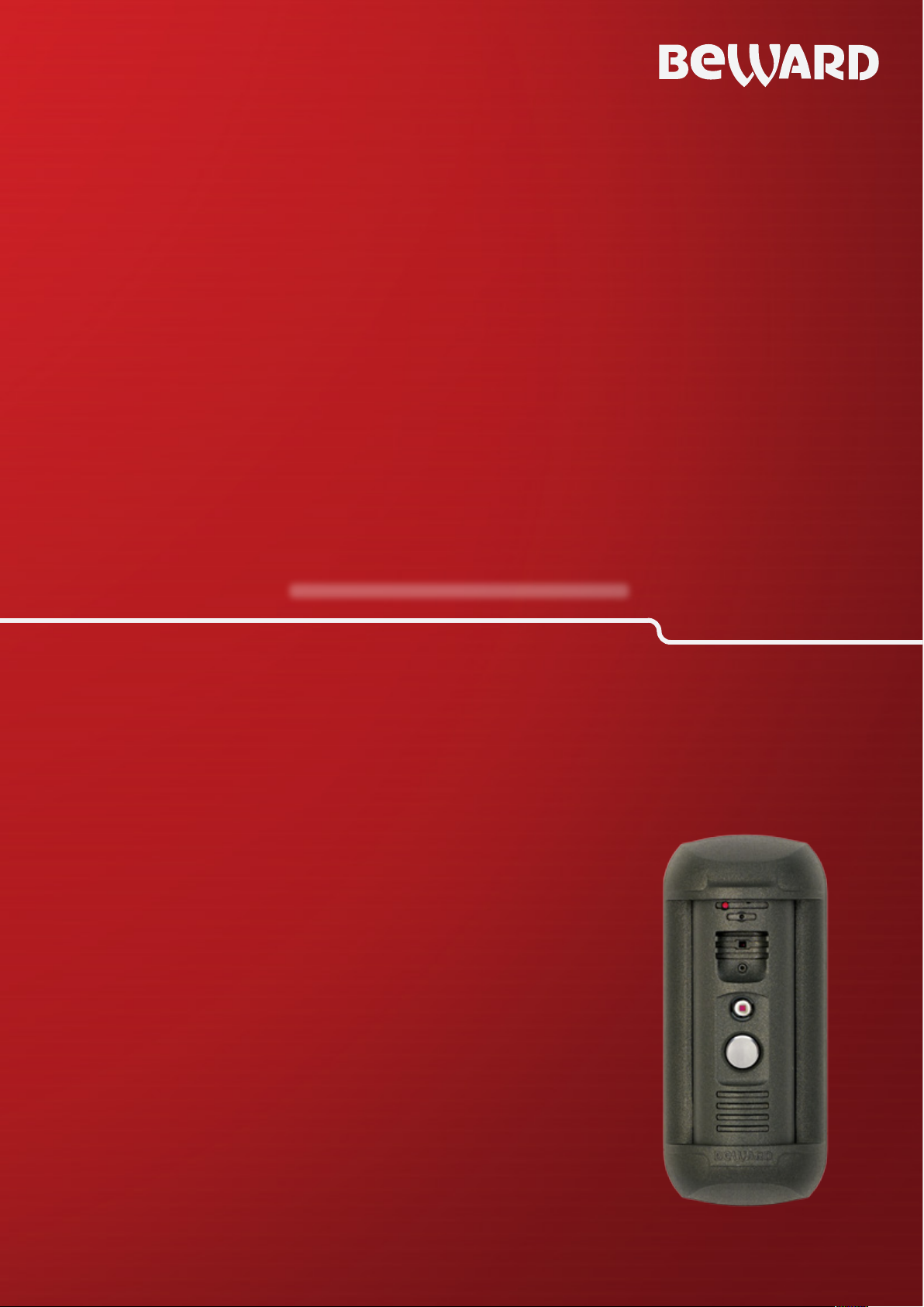
IP Video Door Station
DS03M(P)
Electronic Motorized Lock Control
Multiaccessible User Operation
Built-in IP Video Camera
Two-Way Audio
Page 2
Contents
IP Video Door Station DS03M(P) Installation User Manual
1
Contens
CHAPTER 1. SAFETY INSTRUCTIONS ........................................................................................... 2
CHAPTER 2. DESCRIPTION ............................................................................................................ 4
2.1. KEY FEATURES ...................................................................................................................... 4
2.2. PACKAGE CONTENTS .............................................................................................................. 5
CHAPTER 3. OVERVIEW ................................................................................................................. 6
3.1. DOOR STATION ................................................................................................ ...................... 6
3.2. CONTROLLER ........................................................................................................................ 7
CHAPTER 4. DOOR STATION INSTALLATION .............................................................................. 9
4.1. GENERAL INFORMATION ......................................................................................................... 9
4.2. INSTALLATION RECOMMENDATIONS ....................................................................................... 10
4.3. DOOR STATION MOUNTING .................................................................................................... 12
4.4. WIRED CONNECTION TO A NETWORK .................................................................................... 19
CHAPTER 5. SETTING THE WIRED CONNECTION FOR WINDOWS 7 ....................................... 20
5.1. DEFINING THE LOCAL NETWORK PARAMETERS FOR WIRED CONNECTION ............................... 20
5.1.1. Defining the Local Network Parameters when using a Dynamic IP Address ............... 24
5.2. CHANGING THE LOCAL NETWORK PARAMETERS .................................................................... 27
5.3. ACCESSING THE DOOR STATION USING INTERNET EXPLORER ................................................. 31
5.4. ACCESSING THE DOOR STATION’S WEB INTERFACE ............................................................... 31
5.5. CONFIGURING DOOR STATION NETWORK SETTINGS THROUGH THE WEB INTERFACE ............... 35
5.6. RESTORING NETWORK SETTINGS OF PC TO THE PREVIOUS VALUES ....................................... 36
5.7. VERIFYING THE CONNECTION SETTINGS ................................................................................ 39
APPENDIX. FACTORY DEFAULTS ............................................................................................... 42
Page 3
Chapter 1. Safety Instructions
IP Video Door Station DS03M(P) Installation User Manual
2
ATTENTION!
Use accessories recommended by the manufacturer only. The use of the improper accessories may
cause device breakdown.
ATTENTION!
In case of malfunction of the product contact our Service Center.
Chapter 1. Safety Instructions
Before using the product
This product complies with all safety rules. However, improper use of any electric device
can be a cause of fire and bring to property damage. Before you start using this door station,
please read this User Manual carefully.
Follow the operating instructions
Do not use and store this door station in severe environment:
avoid extremely low or high ambient temperatures (the door station’s operating
temperature is -40°C to +50°C)
avoid exposure to direct sunlight and do not locate the door station near any heat
sources
do not locate the door station near any electrical appliances which can be
electromagnetic transmitters
avoid exposure to high vibration
In case of:
detection of a strange smell or smoke
penetration of any liquid or foreign objects into the door station
the door station has been dropped or damaged
Do the following:
unplug the power cord and disconnect all other cords from the door station
contact our Service Center. You can find contact information on our website:
http://www.beward.eu/.
Transportation
Ttransport the door station carefully, using the original box and protective packing.
Page 4
Chapter 1. Safety Instructions
IP Video Door Station DS03M(P) Installation User Manual
3
Ventilation
To prevent overheating of the device, keep free air circulation in the area where the door
station is located.
Cleaning
Use a soft, dry cloth for cleaning door station’s external surfaces. It is acceptable to use
some detergent for removing persistent dirt, but not the volatile cleaners such as the alcoholcontaining solvents, benzene and so on, because of the risk to damage the door station’s housing.
Page 5
Chapter 2. Description
IP Video Door Station DS03M(P) Installation User Manual
4
Chapter 2. Description
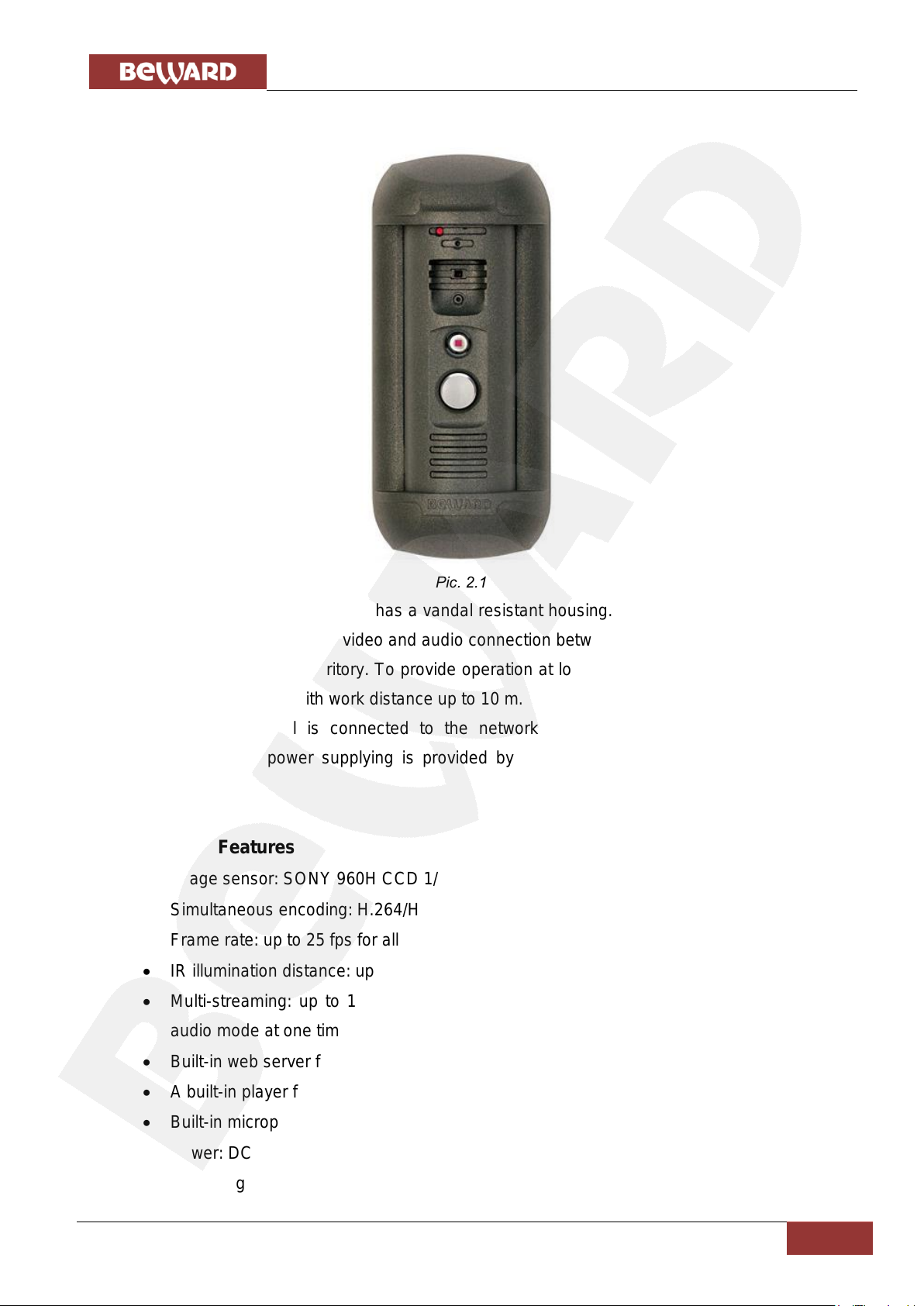
Pic. 2.1
IP Video Door Station DS03M has a vandal resistant housing. Built-in speaker, microphone
and IP camera allow establishing video and audio connection between a guest and the operator as
well as watching the nearby territory. To provide operation at low light level the door station has a
built-in infra-red illuminator with work distance up to 10 m.
The DS03M model is connected to the network using the 10/100BASE-TX Ethernet
interface. In this case power supplying is provided by a DC 12V power source. The DS03MP
model supports PoE.
2.1. Key Features
Image sensor: SONY 960H CCD 1/3, DSP Effio-E Day/Night
Simultaneous encoding: H.264/H264, Н.264/MJPEG, MJPEG /MJPEG
Frame rate: up to 25 fps for all resolutions
IR illumination distance: up to 10 m
Multi-streaming: up to 10 nonidentical streams (only one user can be in the two-way
audio mode at one time)
Built-in web server for viewing and setting
A built-in player for watching records
Built-in microphone and speaker
Power: DC 12V, 0.6A / PоE 802.3af Class 0 (for DS03MP only)
Operating temperature: -40°С to +50°С
Page 6
Chapter 2. Description
IP Video Door Station DS03M(P) Installation User Manual
5
ATTENTION!
Package contents and door station specification are subject to change without notice.
Protocols supported: TCP/IP, IPv4/IPv6, UDP, HTTP, NTP, RTP, RTSP, DHCP, DNS
ONVIF support
2.2. Package contents
DS03M(P) door station
Bracket with mounting kit
Hexagonal socket screw with L-key
RJ45-S01 connector (2 pcs)
DS03M(C1) / DS03M(C1P) controller with terminal block
CD with product documentation and software
Page 7
Chapter 3. Overview
IP Video Door Station DS03M(P) Installation User Manual
6
Chapter 3. Overview
3.1. Door station
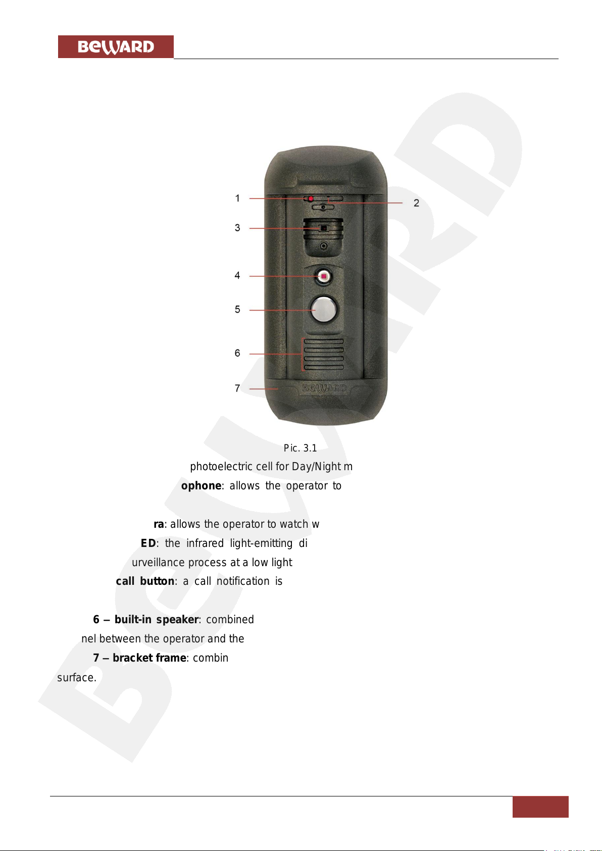
Door station front view is given below:
Pic. 3.1
1 – light sensor: a photoelectric cell for Day/Night modes automatic changing.
2 – built-in microphone: allows the operator to hear what happens in the surveillance
area.
3 – IP camera: allows the operator to watch what happens in the surveillance.
4 – IR LED: the infrared light-emitting diodes used instead of standard electric lamps
provide video surveillance process at a low light level as well as at night.
5 – call button: a call notification is sent to the operator when the guest presses this
button.
6 – built-in speaker: combined with the built-in microphone it provides a two-way audio
channel between the operator and the guest.
7 – bracket frame: combined with a bracket plate it fixes the door station on the mounting
surface.
Page 8
Chapter 3. Overview
IP Video Door Station DS03M(P) Installation User Manual
7
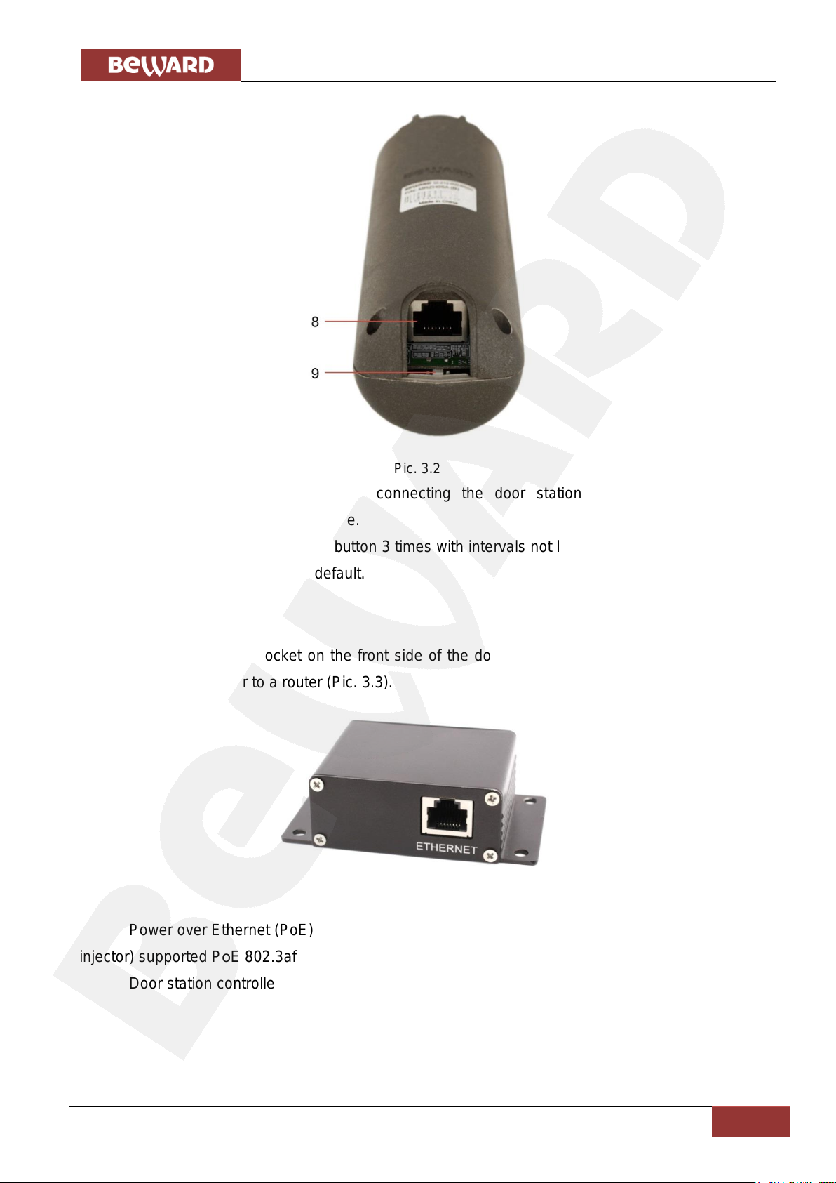
Pic. 3.2
8 – RJ45 socket: is used for connecting the door station to the DS03M(C1) or
DS03M(C1P) controller by a patch cable.
9 – default button: press this button 3 times with intervals not less than 1 second during 10
seconds to set the door station by default.
3.2. Controller
There is an RJ45 socket on the front side of the door station controller, which is used for
connecting the controller to a router (Pic. 3.3).
Pic. 3.3
Power over Ethernet (PoE) is_ provided by the DS03M(C1P) controller and a router (or PoE
injector) supported PоE 802.3af Class 0.
Door station controller (DS03M(C1) / DS03M(C1P)) rear view is given below:
Page 9
Chapter 3. Overview
IP Video Door Station DS03M(P) Installation User Manual
8
ATTENTION!
Use only DC 12V power supplies recommended by BEWARD!
Power supplying using both PoE and the «G» and «12V» pins (for DS03M(C1P) controller) at one time is
PROHIBITED!
Maximum current rate provided by the DS03M(C1P) controller for power supplying of the door lock and its
controller is 500 mA. If this value will be exceeded the device may operate incorrect and be damaged. The
device breakdown caused by the exceeding of the maximum current rate is not covered by the warranty.
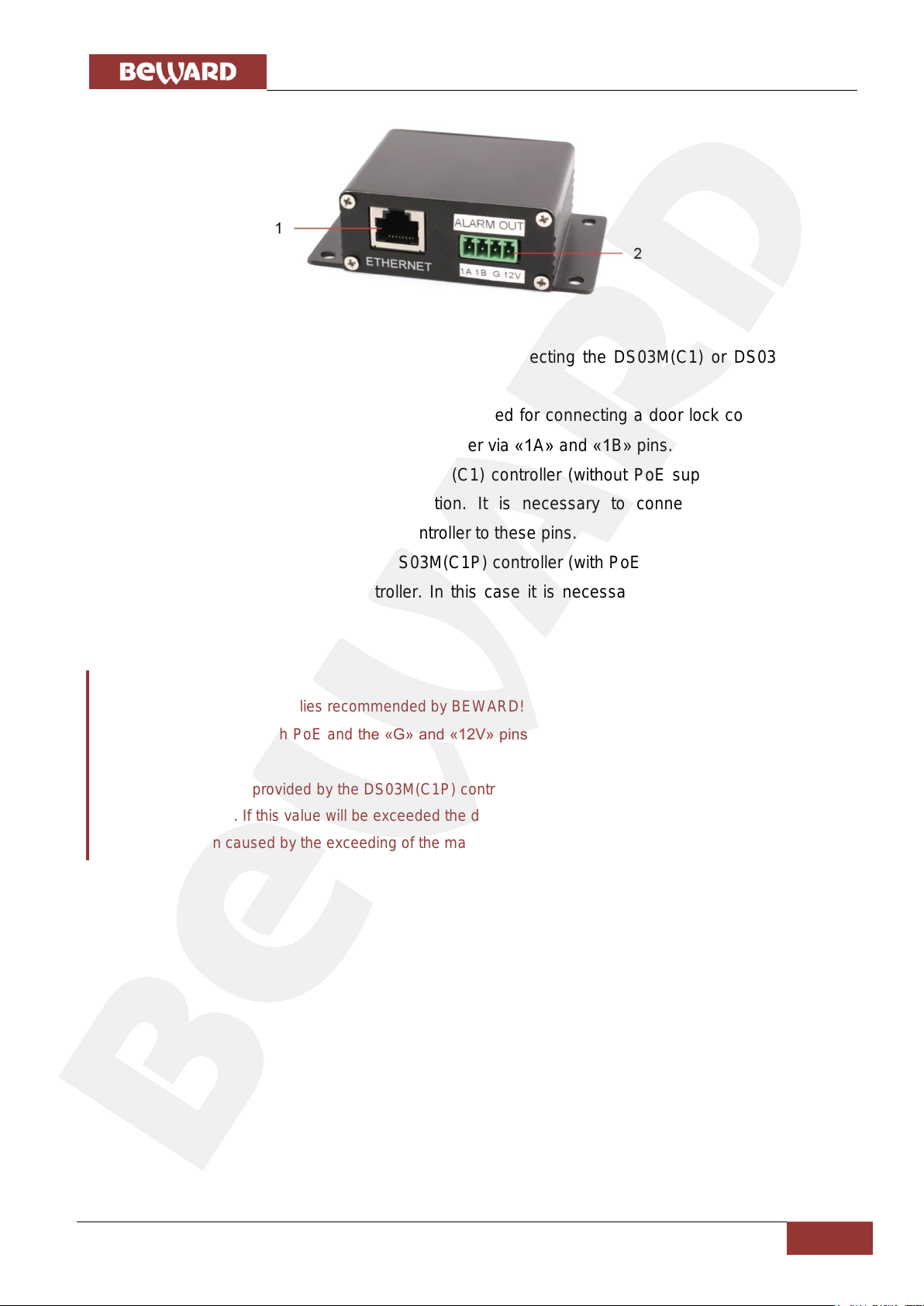
Pic. 3.4
1 – RJ45 socket (ETHERNET): is used for connecting the DS03M(C1) or DS03M(C1P)
controller to the door station by a patch cable.
2 – terminal connector (ALARM OUT): is used for connecting a door lock controller. The
signal opening the door outputs to the lock controller via «1A» and «1B» pins.
The «G» and «12V» pins of the DS03M(C1) controller (without PoE support) are used for
DC 12V power supplying of the door station. It is necessary to connect a power supply
recommended by BEWARD and the lock controller to these pins.
The «G» and «12V» pins of the DS03M(C1P) controller (with PoE support) are used for DC
12V power supplying of the lock controller. In this case it is necessary to connect only the lock
controller to these pins.
Page 10
Chapter 4. Door Station Installation
IP Video Door Station DS03M(P) Installation User Manual
9
switch).
Chapter 4. Door Station Installation
4.1. General Information
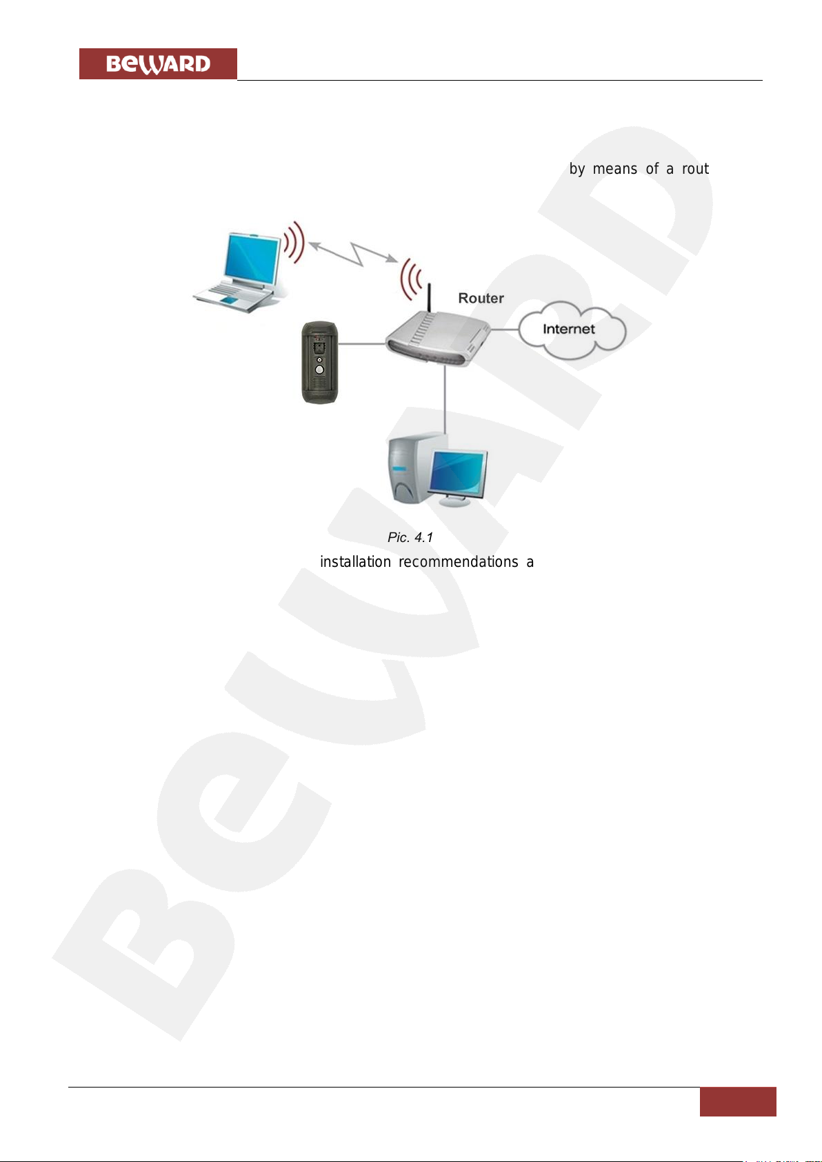
The door station can be connected directly to a computer or by means of a router (a
manual.
Pic. 4.1
The steps to be done and installation recommendations are given below in the present
Page 11
Chapter 4. Door Station Installation
IP Video Door Station DS03M(P) Installation User Manual
10
4.2. Installation Recommendations
It is recommended to install the door station at height of about 1.5 m above the floor.
Then it is recommended to provide the uninterrupted power supply of router, door station,
electronic motorized lock and its controller.
Recommendations on door station placement:
The operating temperature range is -40°С to +50°С.
Avoid exposure to direct sunlight and do not locate the door station near any heat
sources.
Incorrect installation may cause undesirable “blind spots”, zones that are not visible to
the operator.
Do not locate the door station near any electrical appliances which can be
electromagnetic transmitters.
When installing the door station, be convinced of possibility of free laying connection
cables.
Avoid unstable installation, which may allow exposure to high vibration. This may reduce
motion detection performance and image crispness in whole.
The viewing direction should be clearly determined at the moment of the door station’s
installation.
Page 12
Chapter 4. Door Station Installation
IP Video Door Station DS03M(P) Installation User Manual
11
Recommendations on twisted pair cable routing:
In corridors, it is advisable to install electric and feeble-current cables in different
conduits that are disposed on different walls.
Twisted pair and electric cables can be installed in the same conduit using different
sections of the cable that have solid longitudinal partitions with at least 0.25 h of fire
resistance, which are made of non-combustible material and should be positioned in
work areas at distance of 15 meters maximum if the electrical power does not exceed 5
kW.
Electric and feeble-current cables should be placed in parallel to each other at distance
of at least 50 mm in different conduits or different sections of conduit. If the electric field
strength from the electric cables exceeds 3 V/m, you should increase the distance
between the electric and feeble-current cables or reduce the electromagnetic noise.
Twisted pair and electric cables should cross each other at right angles.
Unshielded twisted pair cables should be located at distance of at least 125 mm from
fluorescent gas-discharge lamps or from other high-voltage discharge devices.
Unshielded twisted pair cables should be located at distance of at least 1.5 meters from
electromagnetic interference sources that produce electric field strength exceeding 3
V/m.
Switchboards with pinned unshielded twisted pair cables should be located at distance
of at least 3 meters from electromagnetic interference sources that produce electric field
strength exceeding 3 V/m.
Entire twisted pair cables should be arranged between the points of connection so the
cable run is as short as possible.
Minimum cable bending radius is four times the cable diameter (or 1 inch=2.5 cm) or it is
also acceptable to install the cable so that the cable bending radius is 2 inches (5 cm).
Maximum length of the entire segment is 100 meters.
Page 13
Chapter 4. Door Station Installation
IP Video Door Station DS03M(P) Installation User Manual
12
4.3. Door station mounting
Follow the steps below:
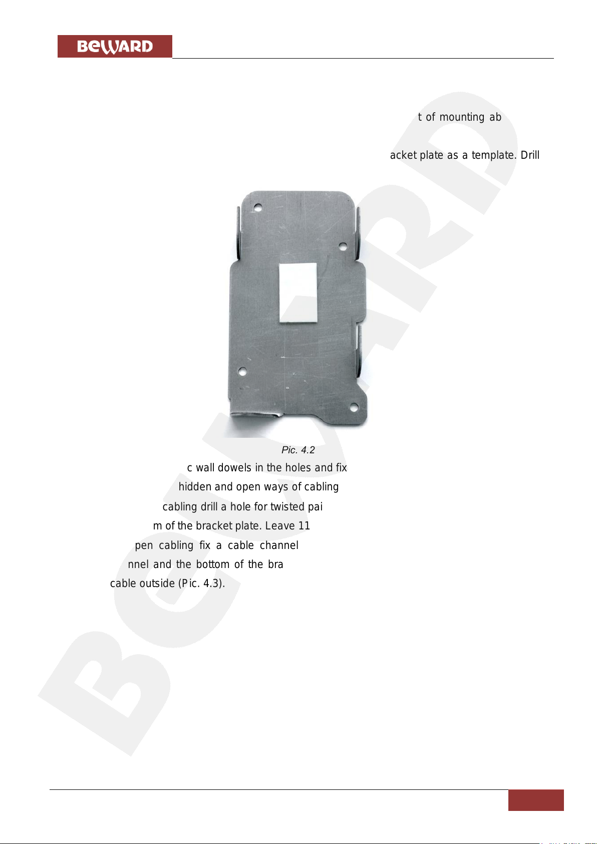
Step 1: take the bracket plate (Pic. 4.2). Choose the right height of mounting above the
floor. The recommended height is about 1.5 m.
Step 2: mark the holes on the mounting surface using the bracket plate as a template. Drill
the holes.
Pic. 4.2
Step 3: insert plastic wall dowels in the holes and fix the bracket plate using four screws.
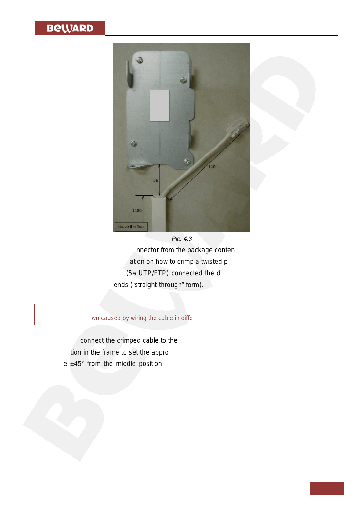
Step 4: there are hidden and open ways of cabling:
for hidden cabling drill a hole for twisted pair cable output at the distance of 25 mm from
the bottom of the bracket plate. Leave 110 mm of the cable outside.
for open cabling fix a cable channel on the wall so that the distance between the
channel and the bottom of the bracket plate would be 36 mm. Leave 110 mm of the
cable outside (Pic. 4.3).
Page 14
Chapter 4. Door Station Installation
IP Video Door Station DS03M(P) Installation User Manual
13
ATTENTION!
The device breakdown caused by wiring the cable in different manner is not covered by the warranty.
Pic. 4.3
Step 5: attach the RJ45 connector from the package contens to the twisted pair cable using
a crimping tool. For more information on how to crimp a twisted pair cable go to the paragraph 4.4.
The twisted pair cable (5е UTP/FTP) connected the door station with its controller should
be wired the same at both ends (“straight-through” form).
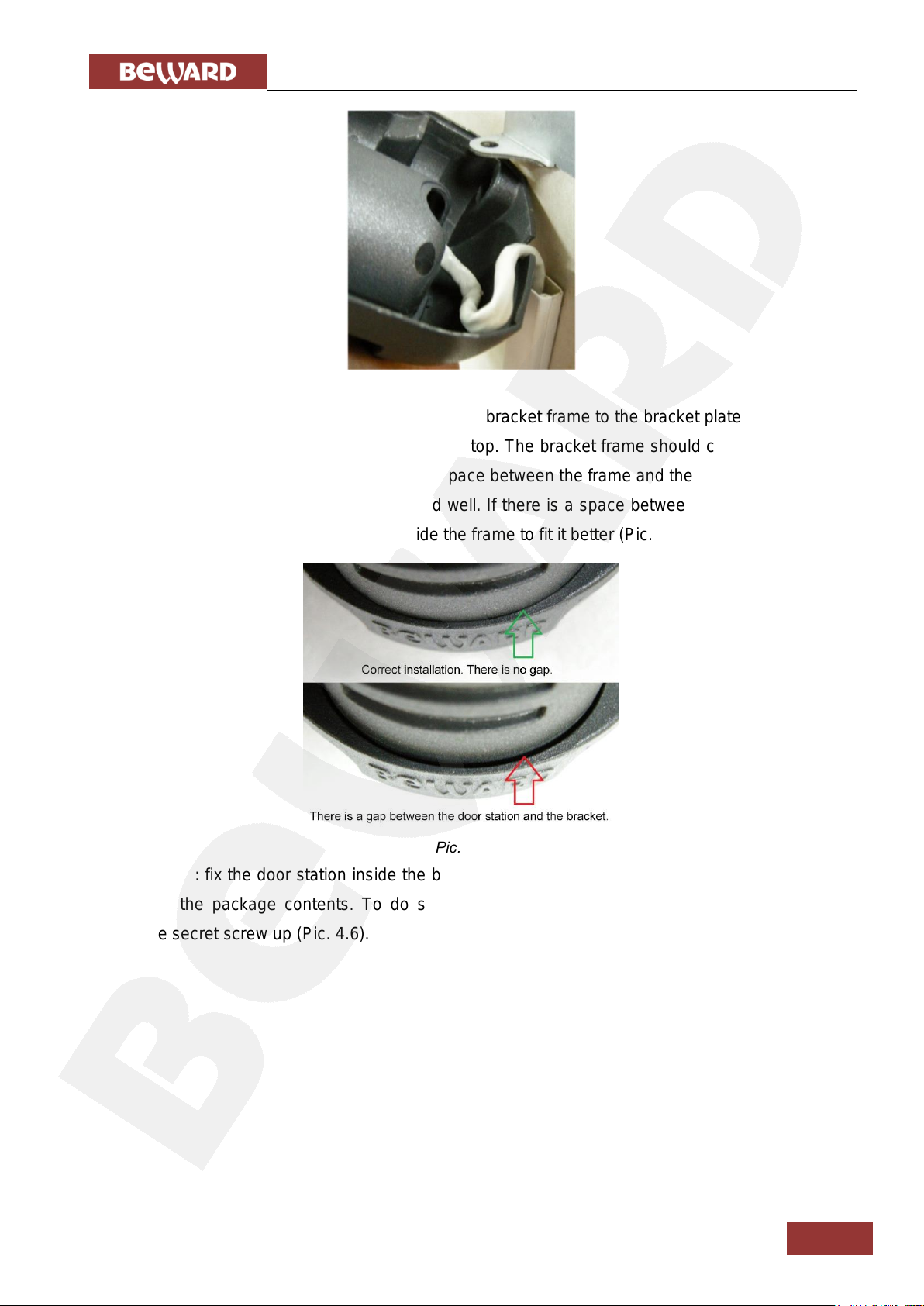
Step 6: connect the crimped cable to the door station and put it in the bracket frame. Rotate
the door station in the frame to set the appropriate view direction of the built-in IP camera (rotating
angles are ±45° from the middle position). Place the free cable as it is showed on the picture
below:
Page 15
Chapter 4. Door Station Installation
IP Video Door Station DS03M(P) Installation User Manual
14
Pic. 4.4
Step 7: apply the door station inserted in the bracket frame to the bracket plate fixed on the
wall. Then move them down with force up to the stop. The bracket frame should completely cover
the bracket plate, and there should not be any space between the frame and the wall.
Step 8: ensure that the bracket is fixed well. If there is a space between the bracket frame
and the door station, change its position inside the frame to fit it better (Pic. 4.5).
Pic. 4.5
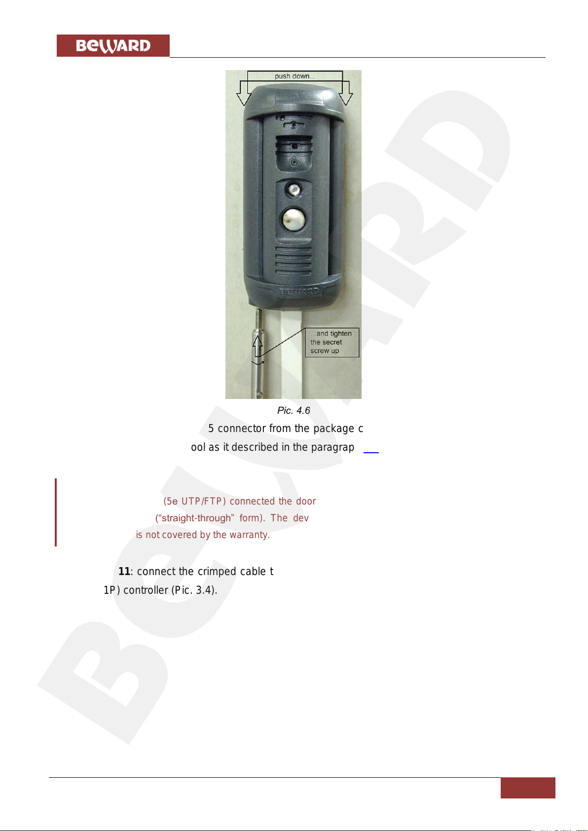
Step 9: fix the door station inside the bracket frame using the hexagonal socket screw and
L-key from the package contents. To do so push the bracket frame down and simultaneously
tighten the secret screw up (Pic. 4.6).
Page 16
Chapter 4. Door Station Installation
IP Video Door Station DS03M(P) Installation User Manual
15
ATTENTION!
The twisted pair cable (5е UTP/FTP) connected the door station with its controller should be wired the
same at both ends (“straight-through” form). The device breakdown caused by wiring the cable in
different manner is not covered by the warranty.
Pic. 4.6
Step 10: attach the RJ45 connector from the package contents to the other end of twisted
pair cable using a crimping tool as it described in the paragraph 4.4.
Step 11: connect the crimped cable to the RJ45 socket (ETHERNET) of the DS03M(C1) /
DS03M(C1P) controller (Pic. 3.4).
Page 17
Chapter 4. Door Station Installation
IP Video Door Station DS03M(P) Installation User Manual
16
ATTENTION!
Use only DC 12V power supplies recommended by BEWARD! For recommendations please visit our
website (www.beward.eu).
It needs to highlight that the maximum current rate provided by the power source for supplying of the
door station, door lock and other equipment should not be exceeded.
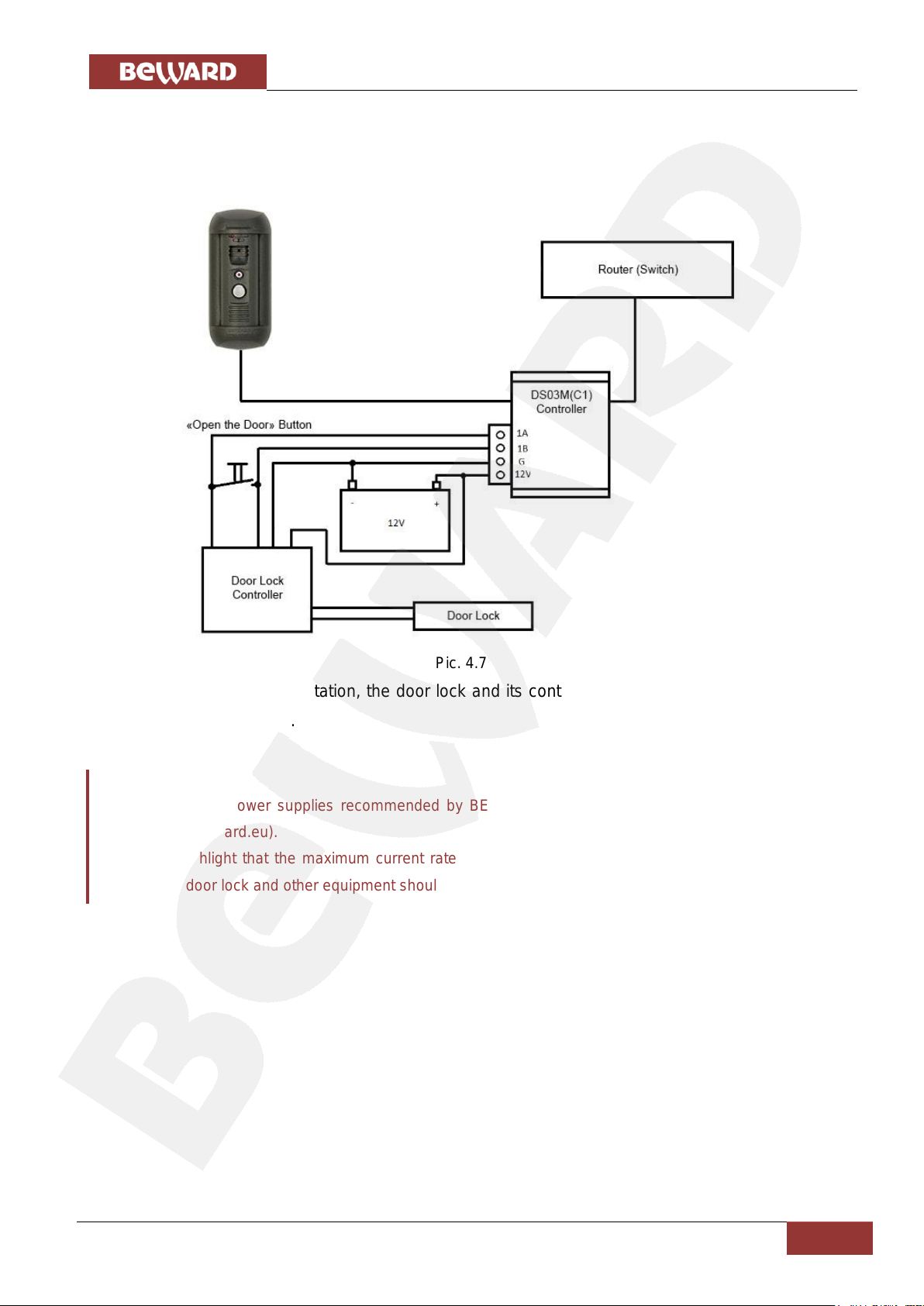
Step 12: connect the door lock controller to the terminal block of the door station controller.
The recommended connection schemes are given below.
1. Without PoE (DS03M package contents):
In this case the door station, the door lock and its controller are supplied with power by an
external 12V power source.
Pic. 4.7
Page 18
Chapter 4. Door Station Installation
IP Video Door Station DS03M(P) Installation User Manual
17
ATTENTION!
Power supplying using both PoE and the «G» and «12V» pins (for DS03M(C1P) controller) at one time is
PROHIBITED!
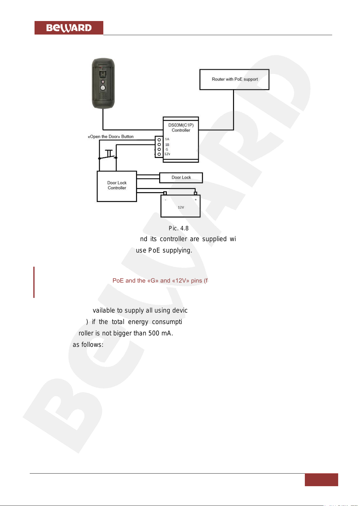
2. With PoE (DS03MP package contents):
Pic. 4.8
In this case the door lock and its controller are supplied with power by an external 12V
power source, but the door station use PoE supplying.
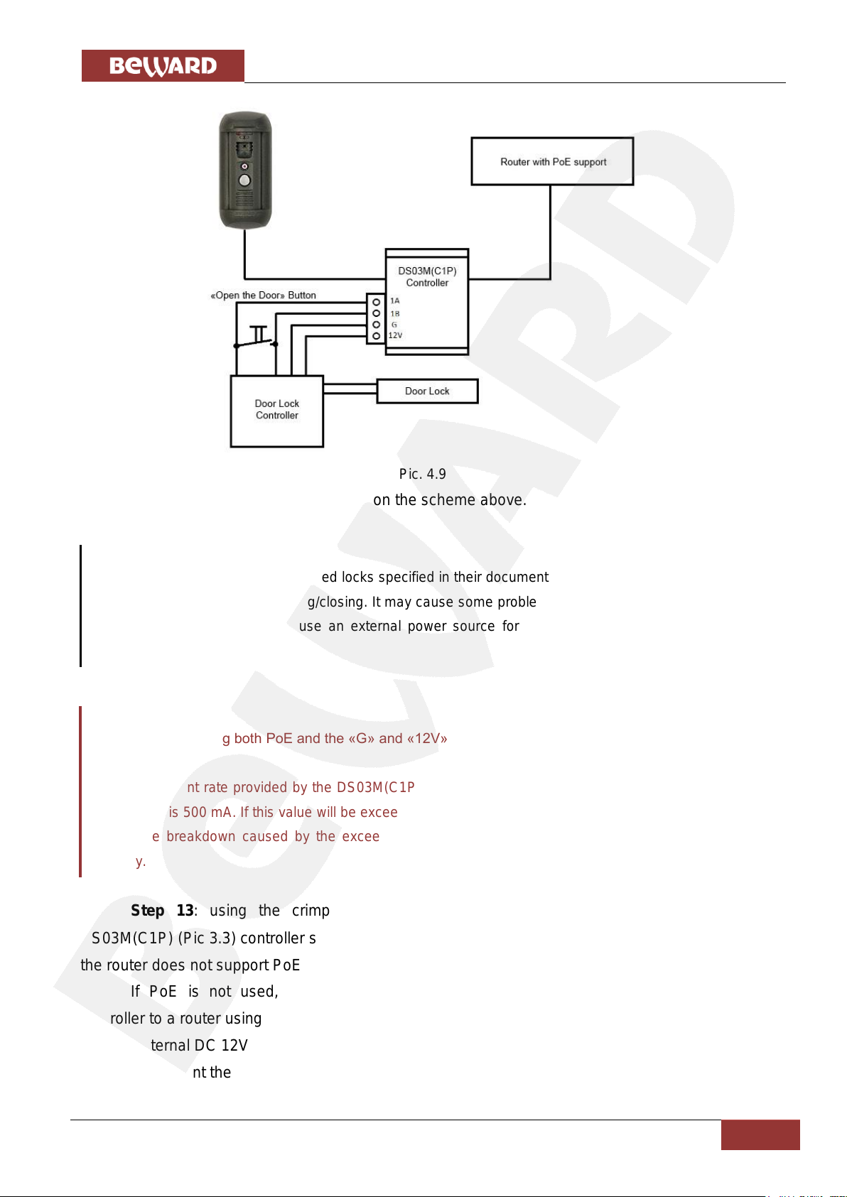
3. It is available to supply all using devices with PoE (without use of an external power
source) if the total energy consumption of using electronic motorized lock and its
controller is not bigger than 500 mA. In this case the recommended connection scheme
is as follows:
Page 19
Chapter 4. Door Station Installation
IP Video Door Station DS03M(P) Installation User Manual
18
NOTE!
The current rate of electronic motorized locks specified in their documentation can be exceeded for short
time at the moment of door opening/closing. It may cause some problems with door station operation. In
this case it is recommended to use an external power source for lock supplying as it shown on the
Pictures 4.7, 4.8.
ATTENTION!
Power supplying using both PoE and the «G» and «12V» pins (for DS03M(C1P) controller) at one time is
PROHIBITED!
Maximum current rate provided by the DS03M(C1P) controller for power supplying of the door lock and
its controller is 500 mA. If this value will be exceeded the device may operate incorrect and be damaged.
The device breakdown caused by the exceeding of the maximum current rate is not covered by the
warranty.
Pic. 4.9
The all devices use PoE supplying on the scheme above.
Step 13: using the crimped cable connect the RJ45 socket (ETHERNET) of the
DS03M(C1P) (Pic 3.3) controller straight to a PoE supported router or by means of a PoE injector if
the router does not support PoE (see schemes 2, 3).
If PoE is not used, then connect the RJ45 socket (ETHERNET) of the DS03M(C1)
controller to a router using the crimped cable and connect the «G» and «12V» pins of the controller
with an external DC 12V power source.
To prevent the door station malfunction use only equipment recommended by BEWARD.
Page 20
Chapter 4. Door Station Installation
IP Video Door Station DS03M(P) Installation User Manual
19
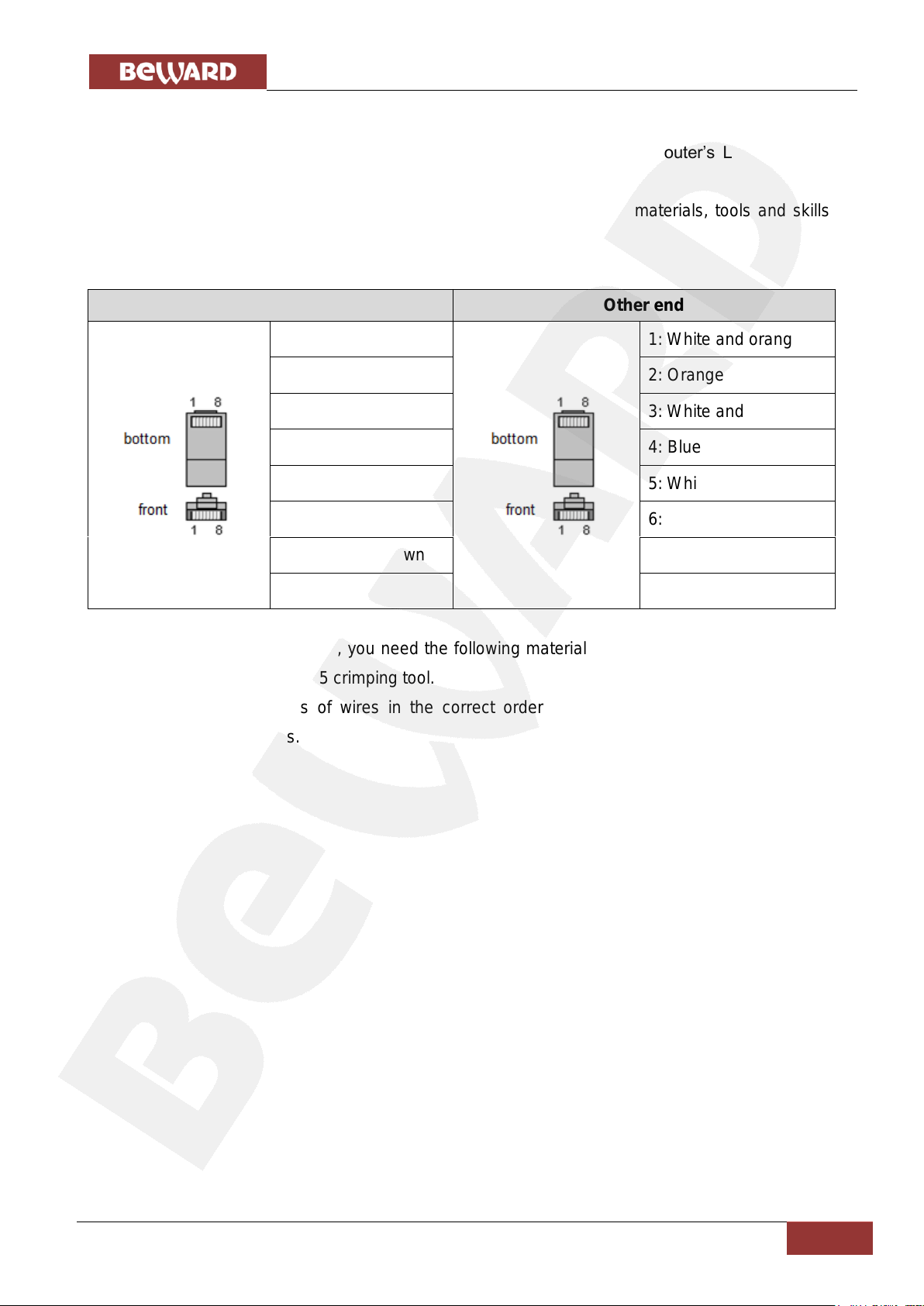
One end
Other end
1: White and orange
1: White and orange
2: Orange
2: Orange
3: White and green
3: White and green
4: Blue
4: Blue
5: White and blue
5: White and blue
6: Green
6: Green
7: White and brown
7: White and brown
8: Brown
8: Brown
4.4. Wired Connection to a Network
Connect the door station’s controller to the local network (to the router’s LAN interface)
using a twisted pair cable with RJ45 connectors.
You can purchase the network cable separately or if you have materials, tools and skills,
you can make it by yourself.
A straight RJ-45 cable (UTP category 5e)
To make a network cable, you need the following materials: a UTP category 5e cable, two
RJ-45 connectors and an RJ-45 crimping tool.
Assembling the pairs of wires in the correct order (see the table above) ensures data
transfer speed of 100 Mbps.
Page 21

Chapter 5. Setting the Wired Connection for Windows 7
IP Video Door Station DS03M(P) Installation User Manual
20
NOTE:
The connection establishment process is shown for OS Windows 7 Ultimate. Despite titles of system menus
and options may differ from the titles of system menus and options that appear in other versions of
Windows, the procedure of the connection establishment process is universal.
Chapter 5. Setting the Wired Connection for Windows 7
To make the door station work together with computers, laptops and other devices in your
local network, you need to connect it to the network according to the network parameters. This
chapter explains how to define the network parameters.
5.1. Defining the Local Network Parameters for Wired Connection
When connecting the door station using an Ethernet cable, you need to define local network
parameters.
To do so, go to Start – Control Panel (Pic. 5.1).
Pic. 5.1
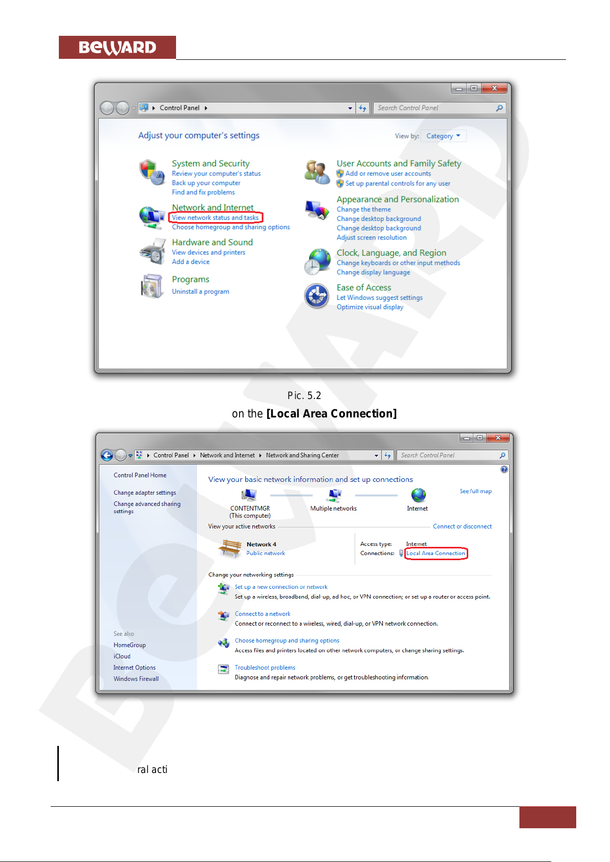
In the opened window click on the [View network status and tasks] in the [Network and
Internet] section (Pic. 5.2).
Page 22
Chapter 5. Setting the Wired Connection for Windows 7
IP Video Door Station DS03M(P) Installation User Manual
21
NOTE:
If there are several active networks, choose the one that you are going to connect your door station to.
Pic. 5.2
In the opened window click on the [Local Area Connection] (Pic. 5.3).
Pic. 5.3
Page 23
Chapter 5. Setting the Wired Connection for Windows 7
IP Video Door Station DS03M(P) Installation User Manual
22
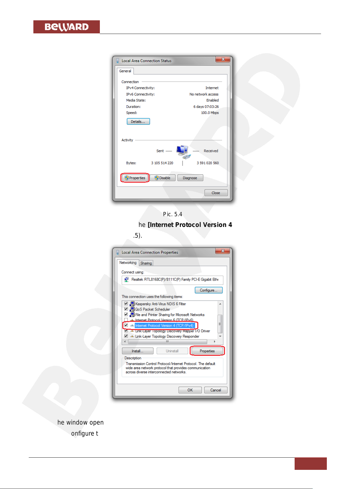
In the opened window click the [Properties] button (Pic. 5.4).
Pic. 5.4
In the opened window select the [Internet Protocol Version 4 (TCP/IPv4)] menu item and
click the [Properties] button (Pic. 5.5).
Pic. 5.5
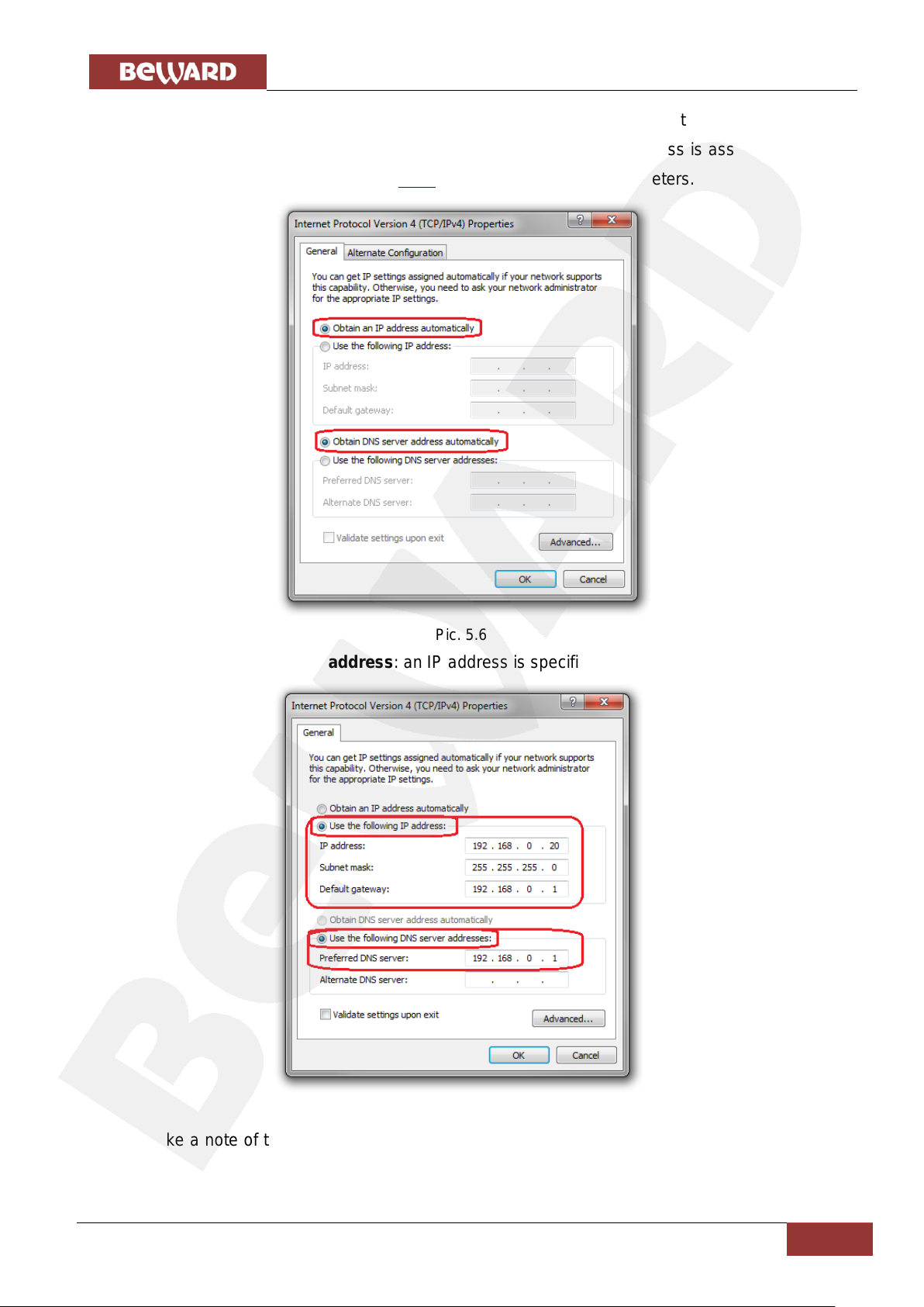
The window opens displaying information about the network connection settings. There are
two ways to configure the IP address:
Page 24
Chapter 5. Setting the Wired Connection for Windows 7
IP Video Door Station DS03M(P) Installation User Manual
23
1. Obtain an IP address automatically: select this option to obtain an IP address
automatically from a DHCP-server on your network (Pic. 5.6). If an IP address is assigned to your
computer automatically, go to paragraph 5.1.1 to define the network parameters.
Pic. 5.6
2. Use the following IP address: an IP address is specified manually (Pic. 5.7).
Pic. 5.7
Make a note of the following parameters: IP address, Subnet mask, Default gateway, DNS
server.
Page 25
Chapter 5. Setting the Wired Connection for Windows 7
IP Video Door Station DS03M(P) Installation User Manual
24
ATTENTION!
If you do not make a note of the network parameters, then it will be impossible to return the computer’s
network settings to their initial state and to connect it to a local network or the Internet after configuring the
door station.
NOTE:
This paragraph explains how to define the local network parameters if an IP address is assigned to your
computer automatically (by DHCP-server).
5.1.1. Defining the Local Network Parameters when using a Dynamic IP Address
Connect a computer (laptop) to your local network using a network cable and wait till the
connection process completing.
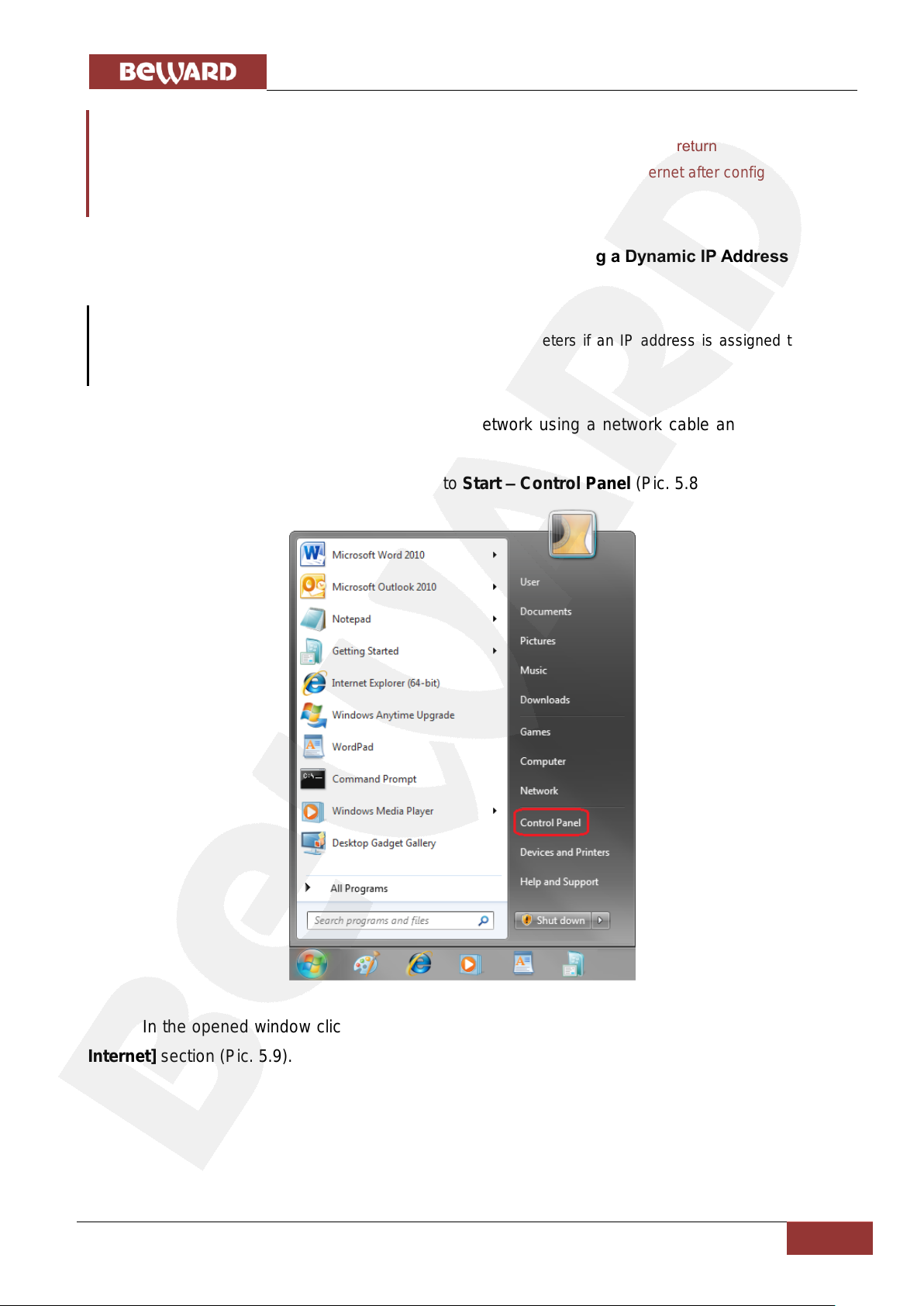
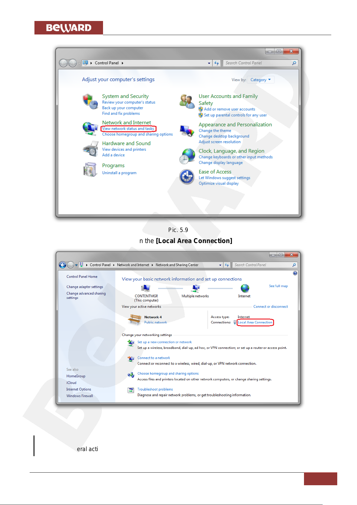
To define the local network settings, go to Start – Control Panel (Pic. 5.8).
Pic. 5.8
In the opened window click on the [View network status and tasks] in the [Network and
Internet] section (Pic. 5.9).
Page 26
Chapter 5. Setting the Wired Connection for Windows 7
IP Video Door Station DS03M(P) Installation User Manual
25
NOTE:
If there are several active networks, choose the one that you are going to connect your door station to.
Pic. 5.9
In the opened window click on the [Local Area Connection] (Pic. 5.10).
Pic. 5.10
Page 27
Chapter 5. Setting the Wired Connection for Windows 7
IP Video Door Station DS03M(P) Installation User Manual
26
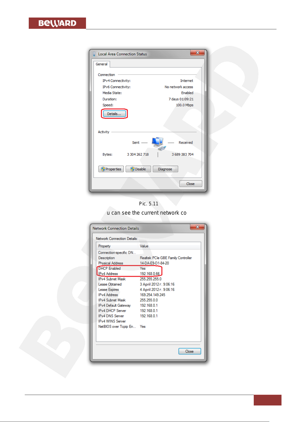
In the opened window click the [Details] button (Pic. 5.11).
Pic. 5.11
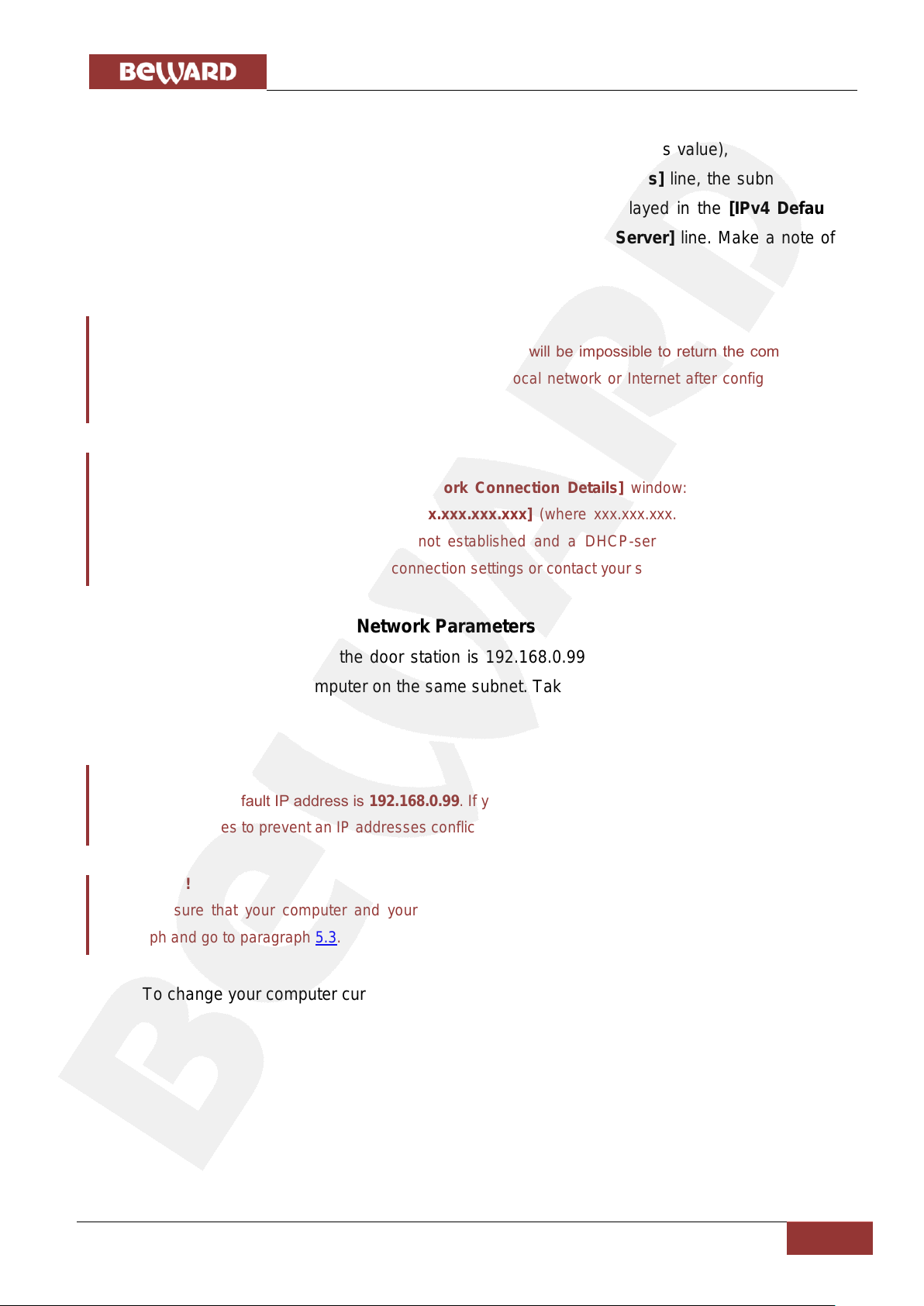
In the opened window you can see the current network connection details (Pic. 5.12).
Pic. 5.12
Page 28
Chapter 5. Setting the Wired Connection for Windows 7
IP Video Door Station DS03M(P) Installation User Manual
27
ATTENTION!
If you do not make a note of the network parameters, then it will be impossible to return the computer’s
network settings to their initial state and to connect it to a local network or Internet after configuring the
door station.
ATTENTION!
If there is the following information in the [Network Connection Details] window: [DHCP Enabled –
Yes], [IPv4 Address Autoconfiguration – xxx.xxx.xxx.xxx] (where xxx.xxx.xxx.xxx is an IP address
value), it means that wired connection was not established and a DHCP-server did not assign your
computer an IP address. Please check the connection settings or contact your system administrator.
ATTENTION!
The door station’s default IP address is 192.168.0.99. If you use several stations, you need to change their
default IP addresses to prevent an IP addresses conflict.
ATTENTION!
If you are sure that your computer and your door station are on the same subnet, you can skip this
paragraph and go to paragraph 5.3.
If you will see the following information in the opened window: [DHCP Enabled – Yes],
[IPv4 Address – xxx.xxx.xxx.xxx] (where xxx.xxx.xxx.xxx is an IP address value), it means that
your computer is assigned the IP address displayed in the [IPv4 Address] line, the subnet mask
displayed in the [IPv4 Subnet Mask] line, the gateway address displayed in the [IPv4 Default
Gateway] line, the DNS server address displayed in the [IPv4 DNS Server] line. Make a note of
these parameters.
5.2. Changing the Local Network Parameters
On default IP address of the door station is 192.168.0.99. To connect to the door station,
you need to get it and your computer on the same subnet. Take notice that each device must have
a unique IP address.
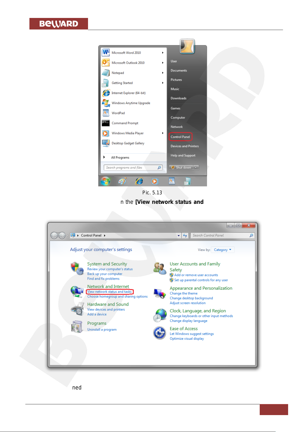
To change your computer current network settings, go to Start – Control Panel (Pic. 5.13).
Page 29
Chapter 5. Setting the Wired Connection for Windows 7
IP Video Door Station DS03M(P) Installation User Manual
28
In the opened window click on the [View network status and tasks] in the [Network and
Internet] section (Pic. 5.14).
Pic. 5.13
Pic. 5.14
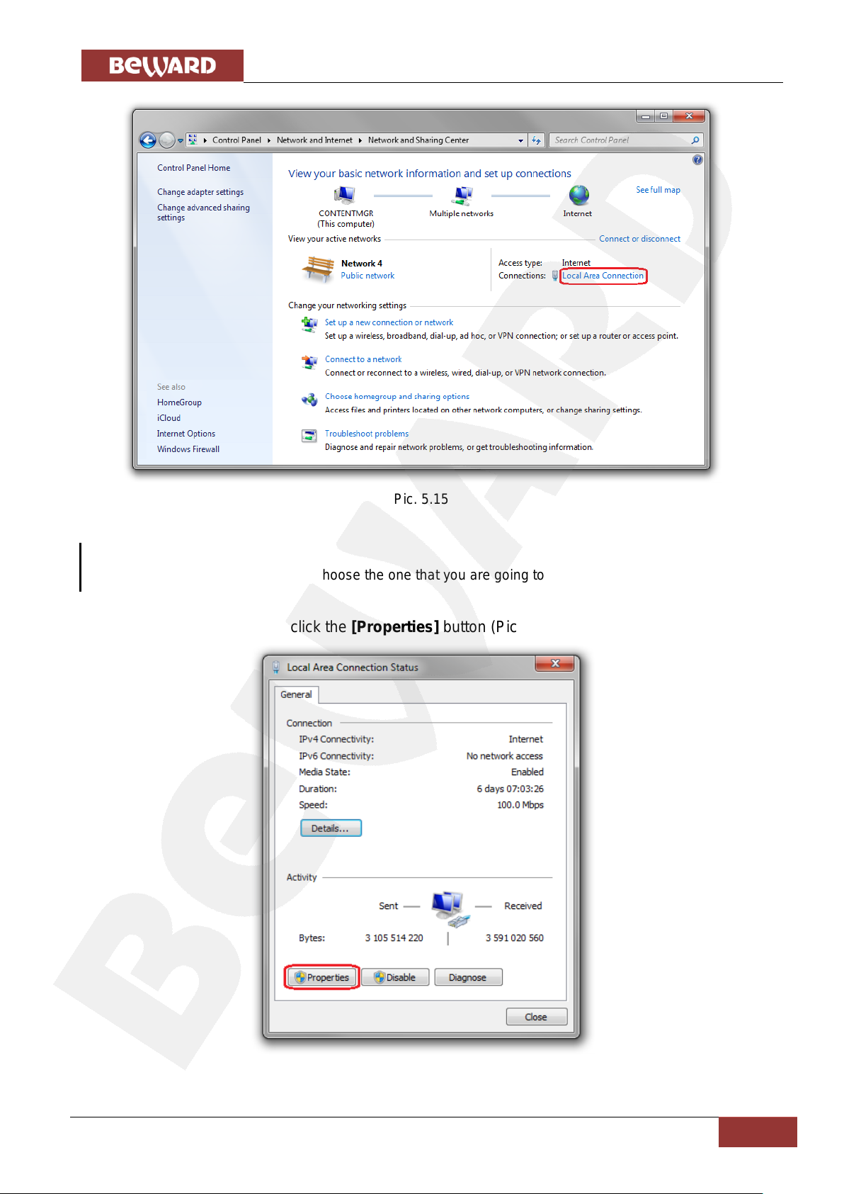
In the opened window, click on the [Local Area Connection] (Pic. 5.15).
Page 30
Chapter 5. Setting the Wired Connection for Windows 7
IP Video Door Station DS03M(P) Installation User Manual
29
NOTE:
If there are several active networks, choose the one that you are going to connect your door station to.
Pic. 5.15
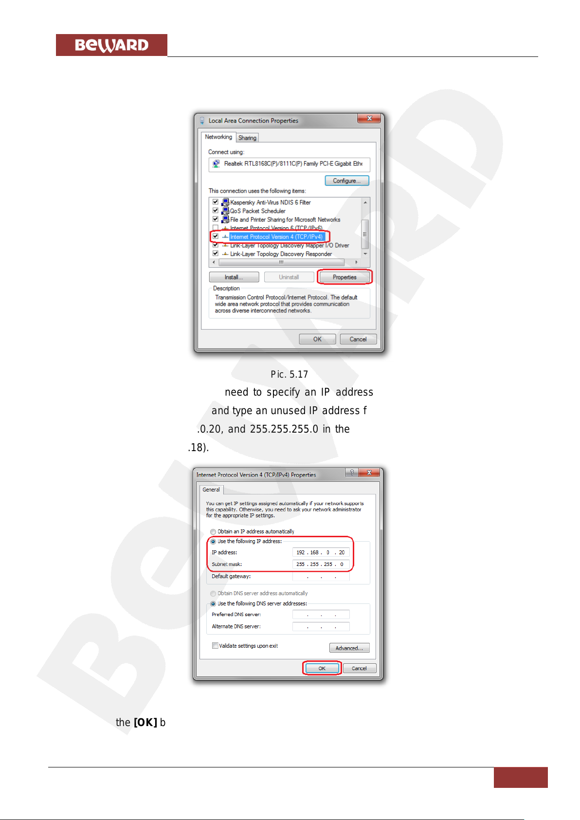
In the opened window, click the [Properties] button (Pic. 5.16).
Pic. 5.16
Page 31
Chapter 5. Setting the Wired Connection for Windows 7
IP Video Door Station DS03M(P) Installation User Manual
30
In the connection properties opened window select the [Internet Protocol Version 4
(TCP/IPv4)] menu item and click the [Properties] button (Pic. 5.17).
Pic. 5.17
In the opened window you need to specify an IP address and a subnet mask. Click the
[Use the following IP address] and type an unused IP address from the same subnet as the door
station, for example, 192.168.0.20, and 255.255.255.0 in the [Subnet mask] field. You can skip
the other parameters (Pic. 5.18).
Pic. 5.18
Click the [OK] button in the all opened windows to save the changes.
Page 32
Chapter 5. Setting the Wired Connection for Windows 7
IP Video Door Station DS03M(P) Installation User Manual
31
ATTENTION!
On default the IP address of the door station is 192.168.0.99 and the http-port is 80.
NOTE:
You do not need to enter a port number if you are connecting through the default HTTP port 80.
NOTE:
Use of the door station’s web interface requires Internet Explorer 9.0 or later to run and display correctly.
5.3. Accessing the Door Station using Internet Explorer
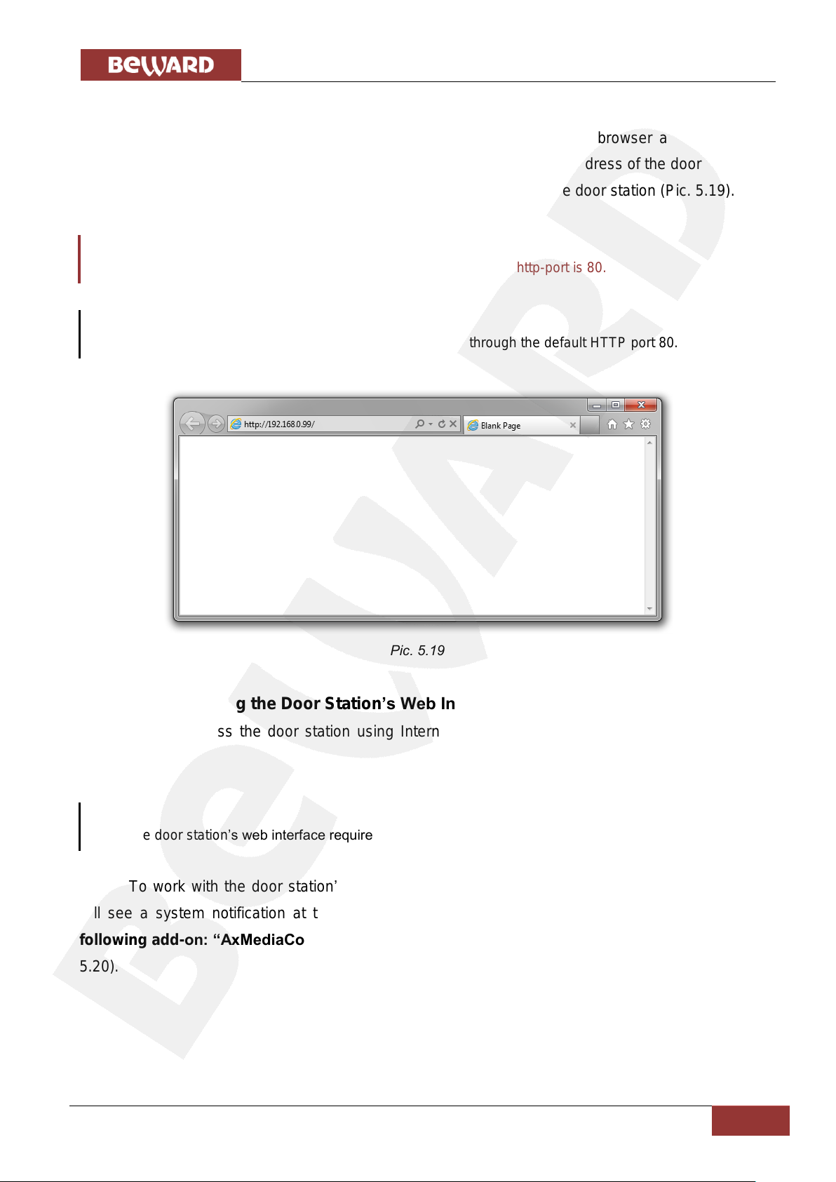
To access this door station through Internet Explorer, launch the browser and enter the
following in the address field: http://<IP>:<port>/, where <IP> is the IP address of the door station,
<port> is the number of the port that is used for HTTP connection to the door station (Pic. 5.19).
Pic. 5.19
5.4. Accessing the Door Station’s Web Interface
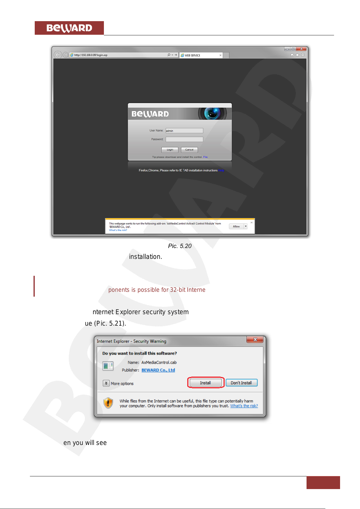
As you access the door station using Internet Explorer an authorization window appears
(Pic. 5.20).
To work with the door station’s web interface you need to install the ActiveX add-on. You
will see a system notification at the bottom of the window: “This webpage wants to run the
following add-on: “AxMediaControl ActiveX Control Module” from “BEWARD Co., Ltd”. (Pic.
5.20).
Page 33
Chapter 5. Setting the Wired Connection for Windows 7
IP Video Door Station DS03M(P) Installation User Manual
32
ATTENTION!
Installation of ActiveX components is possible for 32-bit Internet Explorer only.
Click [Allow] to start the installation.
On default, Internet Explorer security system blocks ActiveX components installation. Click
[Install] to continue (Pic. 5.21).
Pic. 5.20
Pic. 5.21
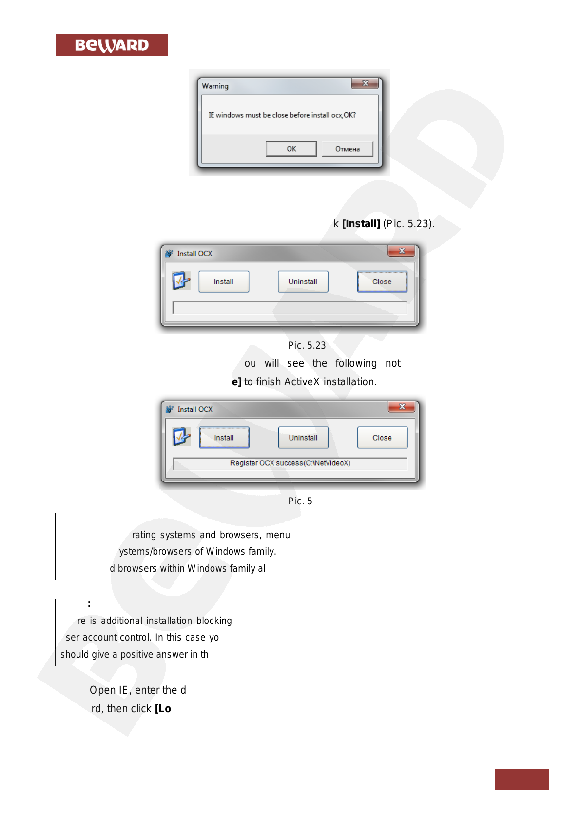
Then you will see the following window (Pic. 5.22):
Page 34
Chapter 5. Setting the Wired Connection for Windows 7
IP Video Door Station DS03M(P) Installation User Manual
33
NOTE:
In the other operating systems and browsers, menu titles or system notifications may be differ from the
same in the systems/browsers of Windows family. This note is applicable to different versions of operating
systems and browsers within Windows family also.
NOTE:
There is additional installation blocking when installing ActiveX components in Windows 7 with enabled
user account control. In this case you will see an additional system notification. To permit installation you
should give a positive answer in the appeared window.
Pic. 5.22
Close Internet Explorer and click [OK].
After that the installation window will appeared. Click [Install] (Pic. 5.23).
Pic. 5.23
After installation completing you will see the following notification: «Register OCX
success(С:\)» (Pic. 5.24). Click [Close] to finish ActiveX installation.
Pic. 5.24
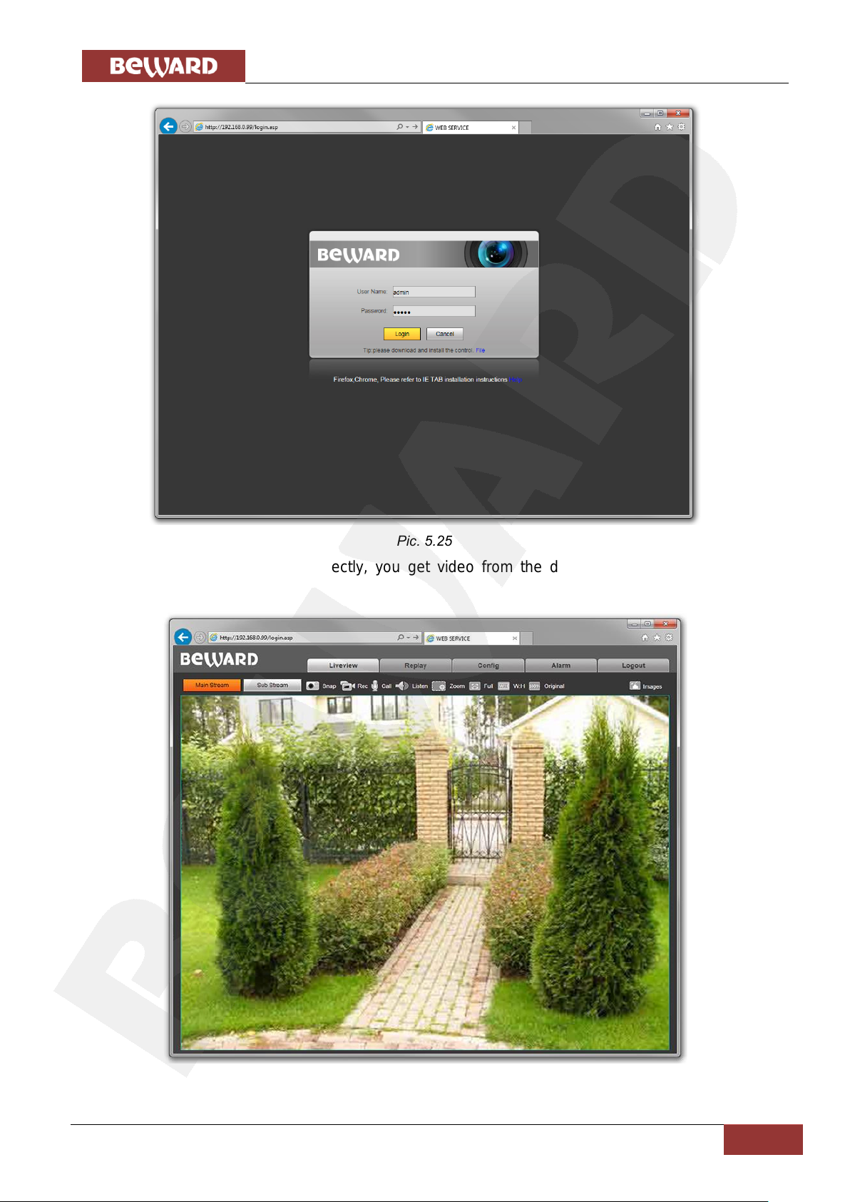
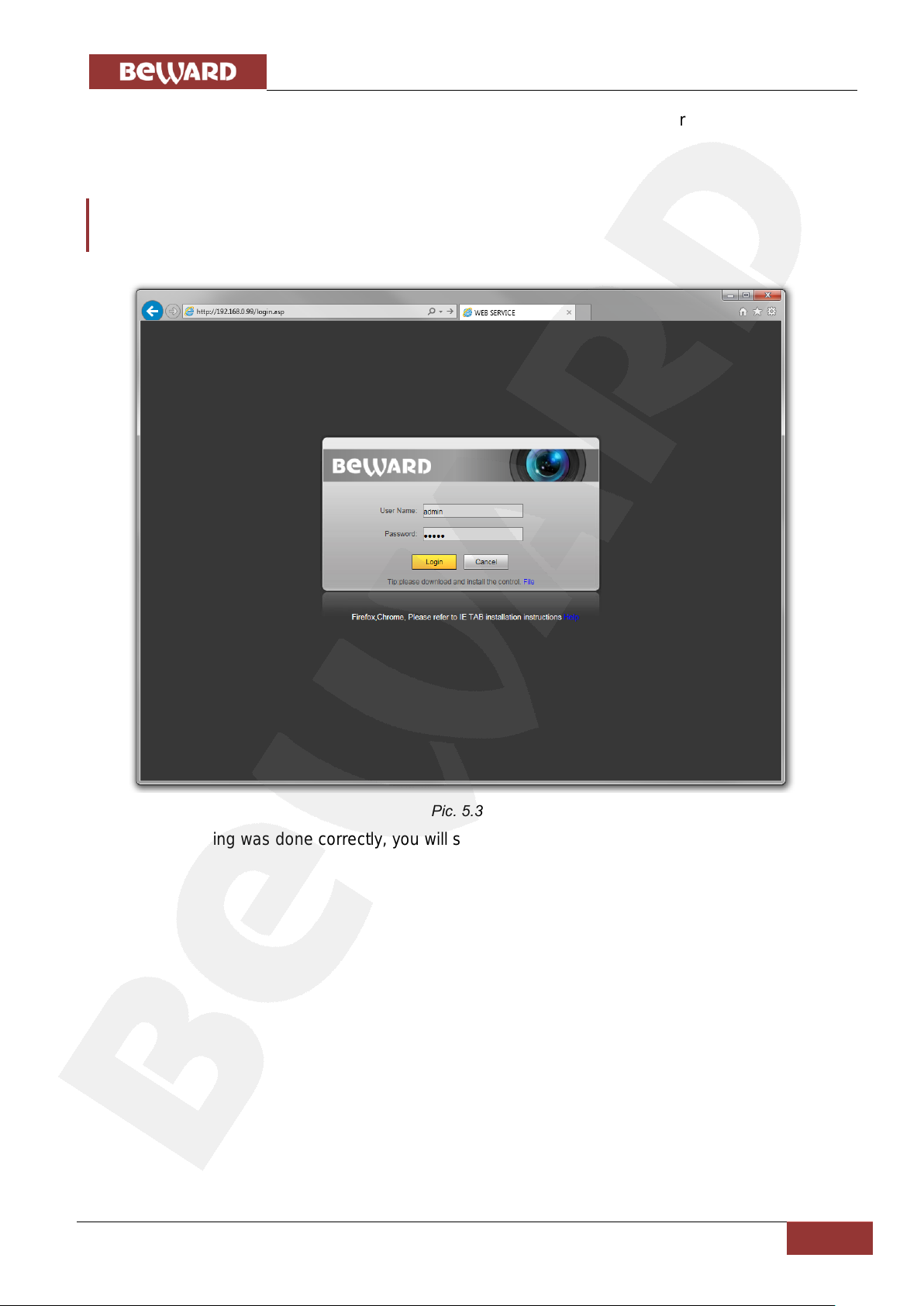
Open IE, enter the door station’s IP address and press [Enter]. Enter the username and the
password, then click [Login] (Pic. 5.25).
Page 35
Chapter 5. Setting the Wired Connection for Windows 7
IP Video Door Station DS03M(P) Installation User Manual
34
If everything was done correctly, you get video from the door station’s camera on your
display (Pic. 5.26).
Pic. 5.25
Pic. 5.26
Page 36
Chapter 5. Setting the Wired Connection for Windows 7
IP Video Door Station DS03M(P) Installation User Manual
35
ATTENTION!
To make your door station and your computer work together, the first three parts of their IP addresses
must be identical but the fourth must differ.
For example, the IP address of your computer is 192.168.50.40. An IP address consists of four octets
separated by dots. In the provided example, the 1st octet is 192, the 2nd octet is 168, the 3rd octet is 50,
and the 4th octet is 40. You need to change the IP address of your door station so that the first three
octets of its IP address were the same as your computer’s IP address. Therefore, the IP address of your
door station must be of the form 192.168.50.XX. You only need to change the fourth octet to a number
different from the IP address of your computer and other network devices.
NOTE:
Contact your system administrator if you need help.
5.5. Configuring Door Station Network Settings through the Web Interface
After connecting the door station to the local network you need to change its network
parameters to get it and your other devices (e.g. computer, laptop etc.) to the same subnet.
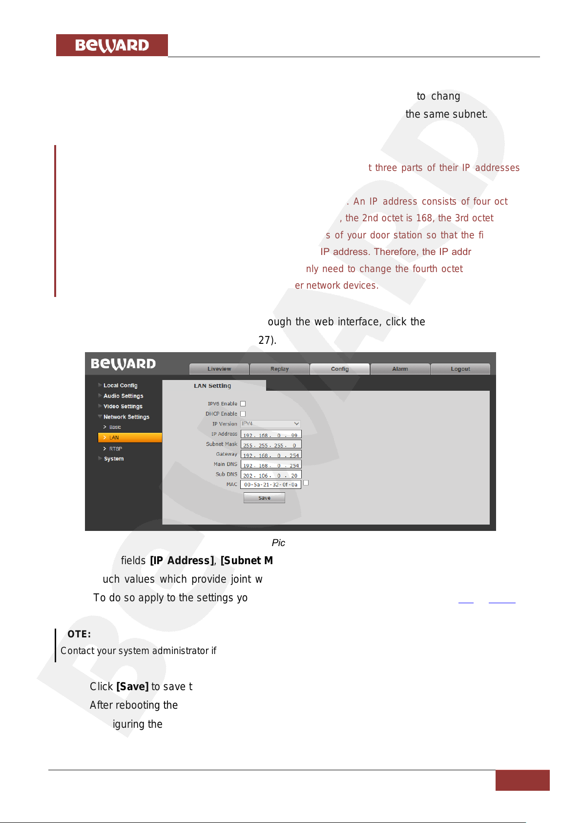
To configure the network settings through the web interface, click the [Config] button and
go to the Network Settings – LAN (Pic. 5.27).
Pic. 5.27
In the fields [IP Address], [Subnet Mask], [Gateway], [Main DNS], [Sub DNS] you need
to enter such values which provide joint work of the door station and other devices in the same
subnet. To do so apply to the settings you had to write out or save in the paragraphs 5.1 or 5.1.1.
Click [Save] to save the changes.
After rebooting the door station will be available on the IP address you specified.
Configuring the door station’s network settings is completed.
Page 37
Chapter 5. Setting the Wired Connection for Windows 7
IP Video Door Station DS03M(P) Installation User Manual
36
5.6. Restoring Network Settings of PC to the Previous Values
To restore the wired connection settings to their previous values, follow the steps below.
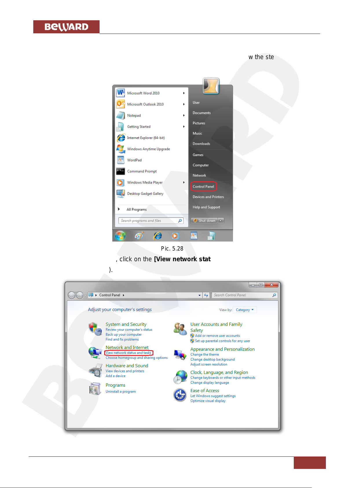
Go to Start – Control Panel (Pic. 5.28).
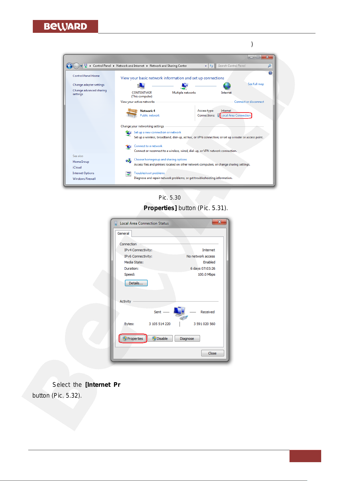
In the opened window, click on the [View network status and tasks] in the [Network and
Internet] section (Pic. 5.29).
Pic. 5.28
Pic. 5.29
Page 38
Chapter 5. Setting the Wired Connection for Windows 7
IP Video Door Station DS03M(P) Installation User Manual
37
In the opened window, click on the [Local Area Connection] (Pic. 5.30).
Pic. 5.30
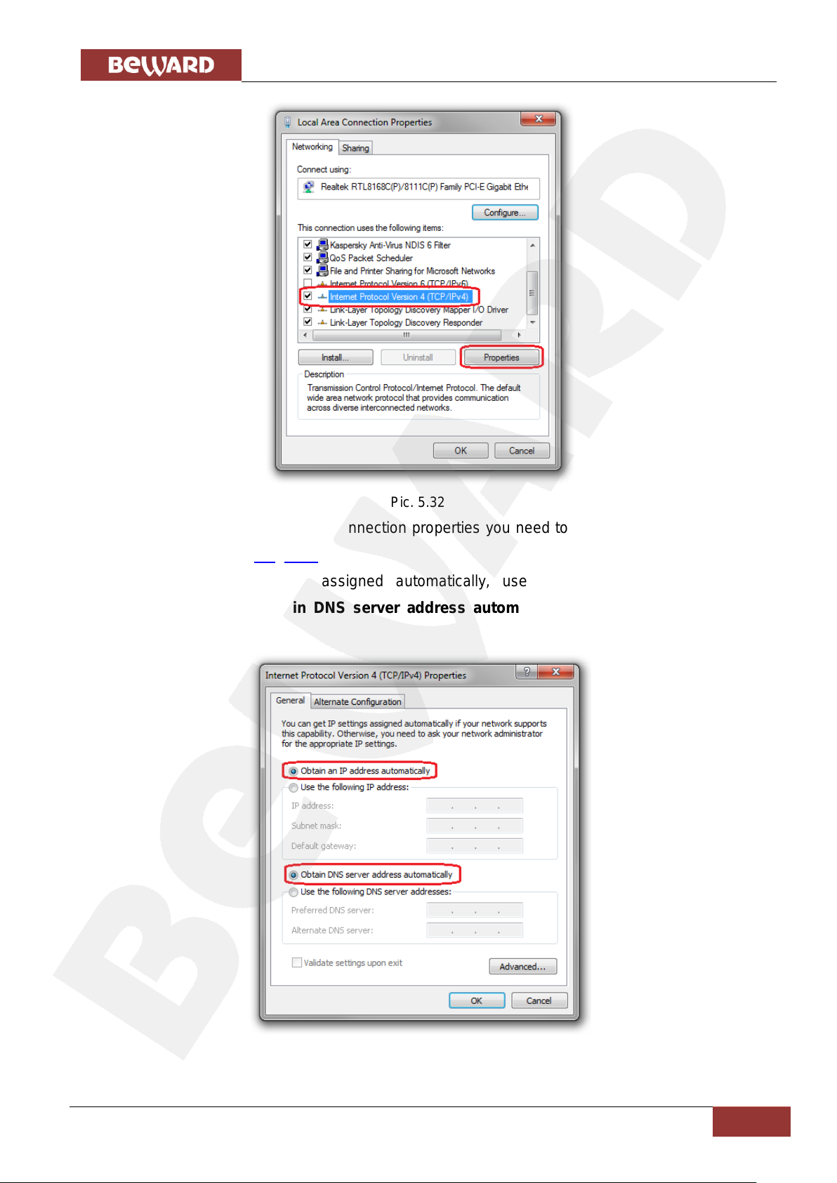
In the opened window, click the [Properties] button (Pic. 5.31).
Pic. 5.31
Select the [Internet Protocol Version 4 (TCP/IPv4)] menu and click the [Properties]
button (Pic. 5.32).
Page 39
Chapter 5. Setting the Wired Connection for Windows 7
IP Video Door Station DS03M(P) Installation User Manual
38
Pic. 5.32
In the opened window of the connection properties you need to specify your initial network
settings (see paragraphs 5.1, 5.1.1).
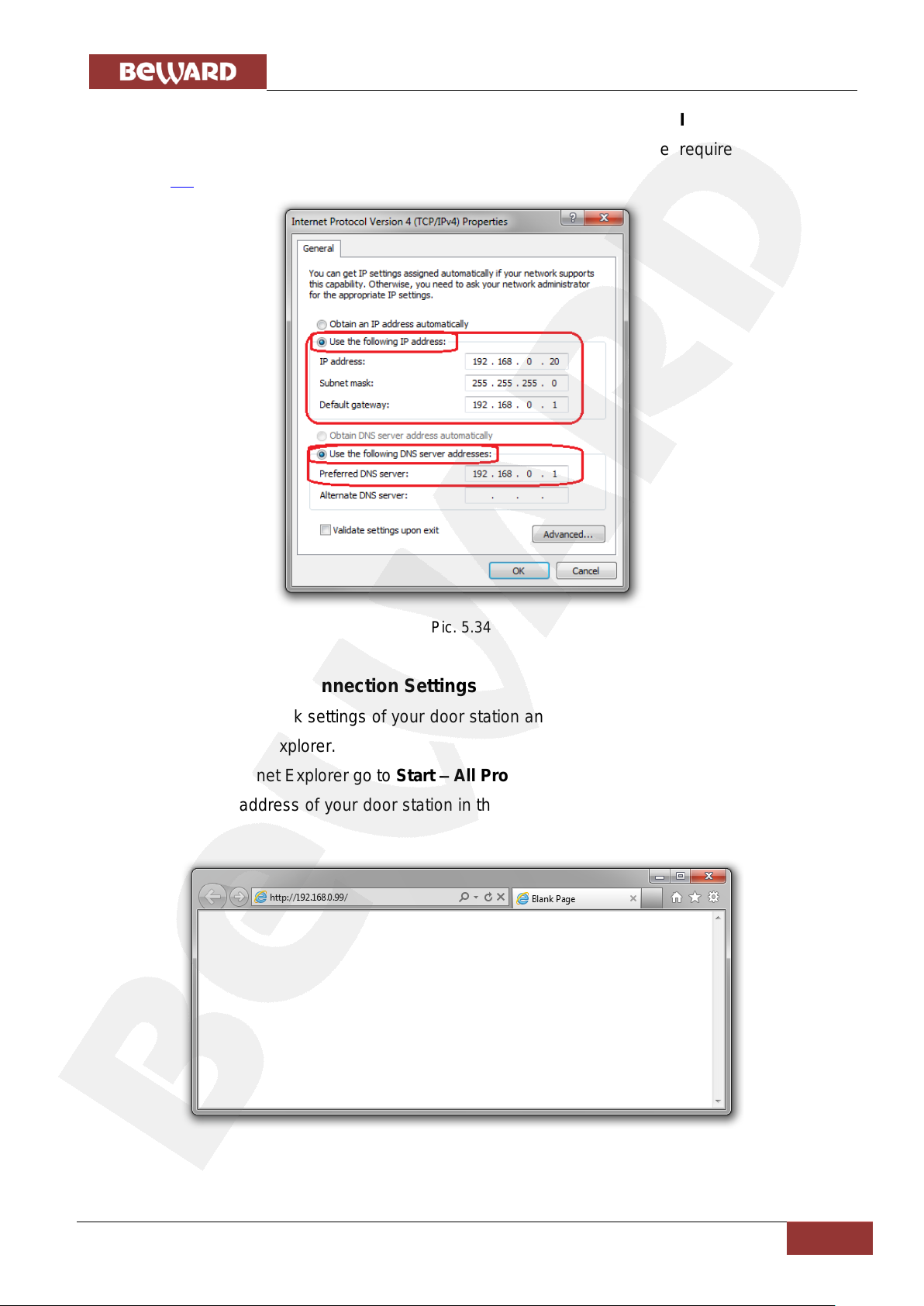
If the IP settings were assigned automatically, use the [Obtain an IP address
automatically] and the [Obtain DNS server address automatically] options (Pic. 5.33), then
click [OK].
Pic. 5.33
Page 40
Chapter 5. Setting the Wired Connection for Windows 7
IP Video Door Station DS03M(P) Installation User Manual
39
If the IP settings were specified manually, use the [Use the following IP address] and the
[Use the following DNS server addresses] options and complete the required fields (see
paragraph 5.1), then click [OK] (Pic. 5.34).
5.7. Verifying the Connection Settings
To verify the network settings of your door station and your computer, you must access the
station through Internet Explorer.
To launch Internet Explorer go to Start – All Programs and click [Internet Explorer].
Enter the IP address of your door station in the address field (e.g. http://192.168.0.99) (Pic.
5.35).
Pic. 5.34
Pic. 5.35
Page 41
Chapter 5. Setting the Wired Connection for Windows 7
IP Video Door Station DS03M(P) Installation User Manual
40
ATTENTION!
The default username is admin, the default password is admin.
If the settings are correct, an authorization window will appear. Enter the username and
password, then click [OK] (Pic. 5.36).
Pic. 5.36
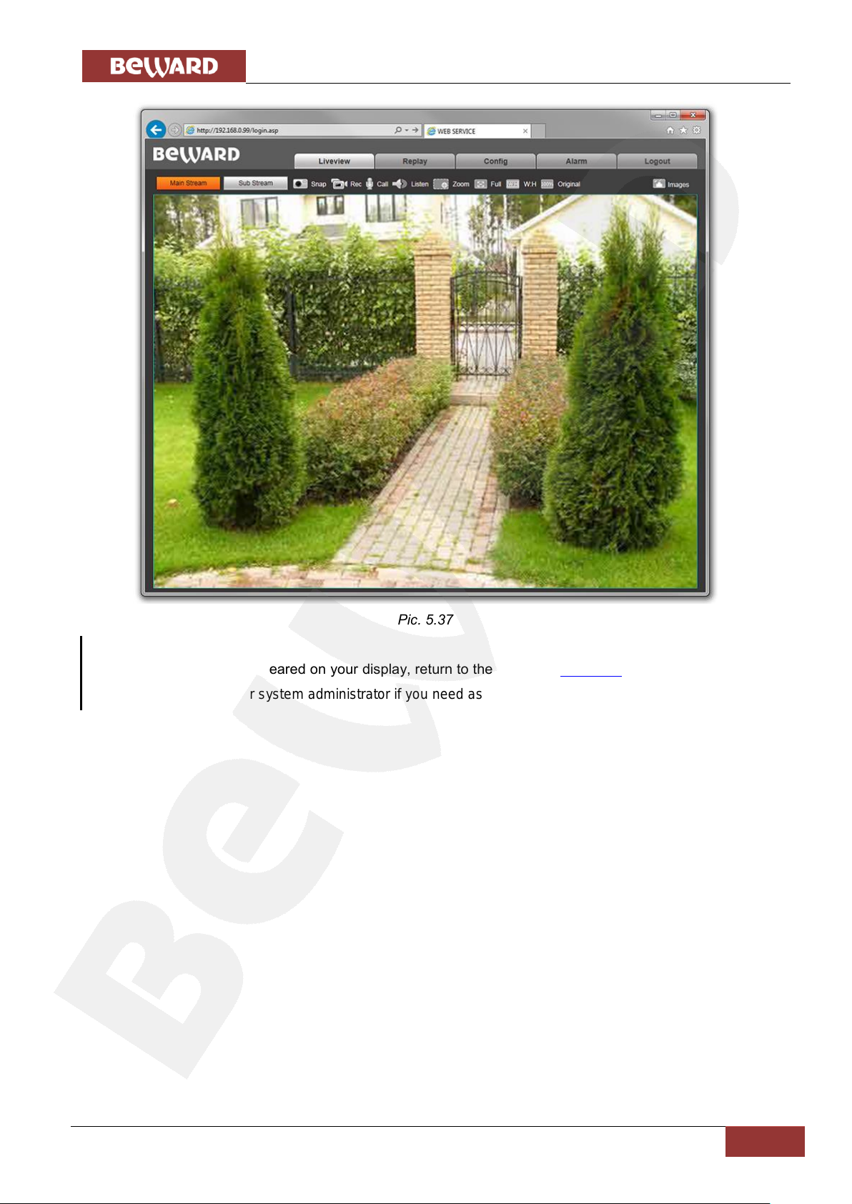
If everything was done correctly, you will see the video image on your display (Pic. 5.37).
Page 42
Chapter 5. Setting the Wired Connection for Windows 7
IP Video Door Station DS03M(P) Installation User Manual
41
NOTE:
If the video image is not appeared on your display, return to the chapter’s beginning and check the setting
step by step. Contact your system administrator if you need assistance.
Pic. 5.37
Page 43
Appendix. Factory Defaults
IP Video Door Station DS03M(P) Installation User Manual
42
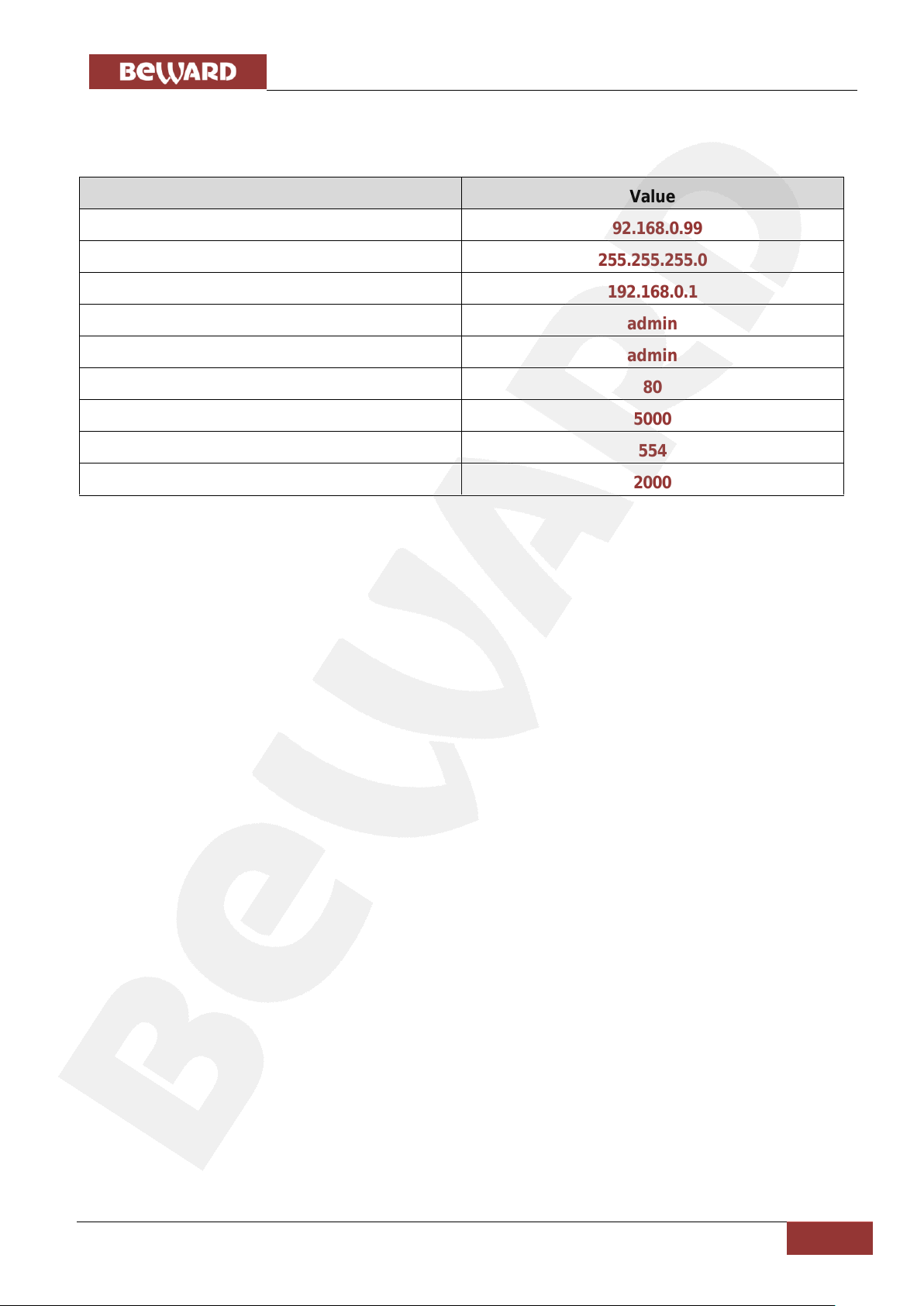
Parameter
Value
IP address
192.168.0.99
Subnet mask
255.255.255.0
Gateway
192.168.0.1
Username (administrator)
admin
Password (administrator)
admin
HTTP port
80
Data port
5000
RTSP port
554
ONVIF port
2000
Appendix. Factory Defaults
 Loading...