

!
!
Innovative Foodservice Equipment
Custom Designed for Performance, Service and Value.
INSTALLATION AND OPERATING
INSTRUCTIONS
Hot Holding Cabinet
Model: CS82-CH8 & CS36-CH3
INTENDED FOR OTHER THAN HOUSEHOLD USE
RETAIN THIS MANUAL FOR FUTURE REFERENCE
UNIT MUST BE KEPT CLEAR OF COMBUSTIBLES AT ALL TIMES
FOR YOUR SAFETY
Do not store or use gasoline or other flammable vapors and liquids in the
vicinity of this or any other appliance.
WARNING
Improper installation, adjustment, alteration, service or maintenance can
cause property damage, injury or death. Read the Installation, Operating and
Maintenance Instructions thoroughly before installing or servicing this
equipment.
!
!
WARNING
Initial heating of unit may generate smoke or fumes and must be done in a
!
This equipment has been engineered to provide you with dependable service when used according to the
instructions in this manual and standard commercial kitchen practices.
Phone: +1
Fax: +1 (214) 565-0976
Toll Free: +1 (800) 527-2100
Website: www.apwwyott.com
E-mail: info@apwwyott.com
well-ventilated area. Overexposure to smoke or fumes may cause nausea or
dizziness.
ANSI/NSF4
(214) 421-7366
BevLes Company, Inc.
729 Third Avenue
Dallas, TX 75226
1
!
Form #780088 11/04
IMMEDIATELY INSPECT FOR SHIPPING DAMAGE
All containers should be examined for damage before and during unloading. The freight carrier has
assumed responsibility for its safe transit and delivery. If equipment is receiveddamaged, either apparent or
concealed, a claim must be made with the delivering carrier.
A) Apparent damage or loss must be noted on the freightbill at the time of delivery. It must then be signed by
the carrier representative (Driver). If this is not done, the carrier may refuse the claim. The carrier should
supply the necessary forms.
B) Concealed damage or loss if not apparent until after equipment is uncrated, a request for inspection
must be made to the carrier within 15 days. The carrier should arrange an inspection.
BE CERTAIN TO HOLD ALL CONTENTS AND PACKAGING MATERIAL.
Installation and start-up should be performed bya qualified installer who thoroughly reads, understands and
follows these instructions.
BevLes Company takes pride in the design and quality of our products. When used as intended and with
proper care and maintenance, you will experience years of reliable operation from this equipment. To
ensure best results, it is important that you read andfollow the instructions in this manual carefully.
Installation and start-up should be performed by a qualified installer who thoroughly reads, understands
and follows these instructions.
If you have questions concerning the installation, operation, maintenance or service of this product, write
Technical Service Department BevLes Company, Inc., 729 ThirdAvenue, Dallas, TX 75226.
SAFETY PRECAUTIONS
Before installing and operating this equipment be sure everyone involved in its operation is fully trained and
aware of all precautions. Accidents and problems can result by a failure to follow fundamental rules and
precautions.
The following words and symbols, found in this manual, alert you to hazards to the operator, service
personnel or the equipment. The words are defined as follows:
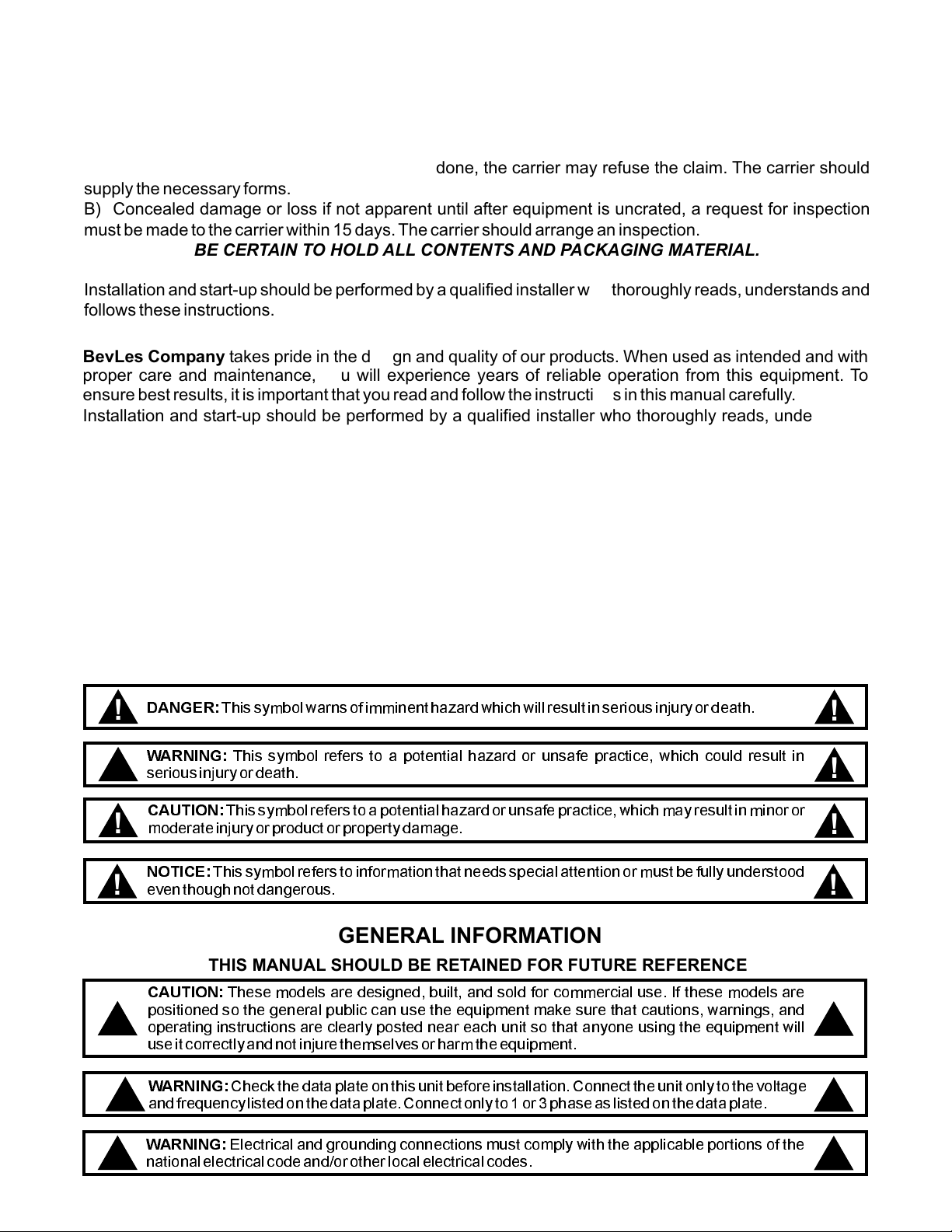
DANGER:
!
WARNING:
!
seriousinjuryor death.
CAUTION:
moderateinjuryorproductor property damage.
!
NOTICE:
eventhoughnot dangerous.
!
Thissymbolwarnsof imminent hazard which will result in serious injury or death.
This symbol refers to a potential hazard or unsafe practice, which could result in
Thissymbol refers to a potential hazardor unsafe practice,which may result in minor or
This symbol refers to information that needs special attention or must be fully understood
!
!
!
!
GENERAL INFORMATION
THIS MANUAL SHOULD BE RETAINED FOR FUTURE REFERENCE
CAUTION:
positioned so the general public can use the equipment make sure that cautions, warnings, and
!
operating instructions are clearly posted near each unit so that anyone using the equipment will
useit correctly and not injurethemselvesorharm the equipment.
WARNING:
!
andfrequencylistedon the data plate. Connect only to1 or 3 phase as listed on the data plate.
WARNING:
!
nationalelectricalcodeand/orotherlocal electrical codes.
These models are designed, built, and sold for commercial use. If these models are
Checkthe data plate on this unit before installation.Connecttheunit only to the voltage
Electrical and grounding connections must comply with the applicable portions of the
2
!
!
!
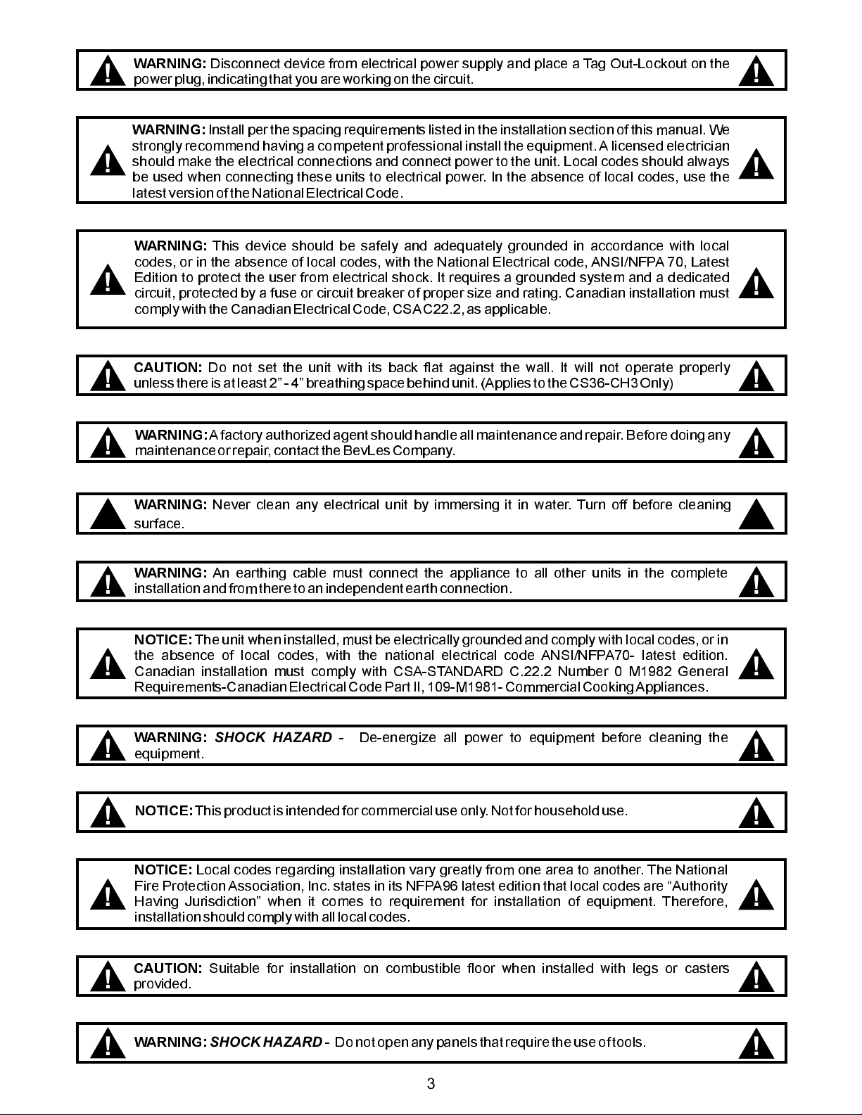
WARNING:
!
powerplug,indicatingthat you are working on the circuit.
Disconnect device from electrical power supply and place a Tag Out-Lockout on the
!
WARNING:
strongly recommend having a competent professional install the equipment.A licensed electrician
should make the electrical connections and connect power to the unit. Local codes should always
!
be used when connecting these units to electrical power. In the absence of local codes, use the
latestversionof the National Electrical Code.
WARNING:
codes, or in the absence of local codes, with the National Electrical code, ANSI/NFPA 70, Latest
Edition to protect the user from electrical shock. It requires a grounded system and a dedicated
!
circuit, protected by a fuse or circuit breaker of proper size and rating. Canadian installation must
complywiththe Canadian ElectricalCode, CSAC22.2,asapplicable.
CAUTION:
!
unlessthereis at least 2- 4 breathingspacebehindunit.(Appliesto the CS36-CH3 Only)
WARNING:
!
maintenanceorrepair,contacttheBevLesCompany.
WARNING:
!
surface.
Installper the spacing requirementslisted in the installationsection of this manual. We
This device should be safely and adequately grounded in accordance with local
Do not set the unit with its back flat against the wall. It will not operate properly
Afactoryauthorizedagentshouldhandle all maintenance and repair. Before doing any
Never clean any electrical unit by immersing it in water. Turn off before cleaning
!
!
!
!
!
WARNING:
installationandfromthereto an independent earth connection.
!
NOTICE:
the absence of local codes, with the national electrical code ANSI/NFPA70- latest edition.
!
Canadian installation must comply with CSA-STANDARD C.22.2 Number 0 M1982 General
Requirements-CanadianElectrical Code PartII, 109-M1981-CommercialCookingAppliances.
WARNING: -
!
equipment.
NOTICE:
!
NOTICE:
Fire Protection Association, Inc. states in its NFPA96 latest edition that local codes are Authority
Having Jurisdiction when it comes to requirement for installation of equipment. Therefore,
!
installationshouldcomplywithalllocal codes.
CAUTION:
!
provided.
An earthing cable must connect the appliance to all other units in the complete
The unit when installed, must be electrically grounded and comply with local codes, or in
SHOCK HAZARD
Thisproductis intended for commercial use only.Notforhouseholduse.
Local codes regarding installation vary greatly from one area to another. The National
Suitable for installation on combustible floor when installed with legs or casters
De-energize all power to equipment before cleaning the
!
!
!
!
!
!
WARNING: -
!
SHOCK HAZARD
Donot open any panels that require theuse of tools.
3
!
TABLE OF CONTENTS
SECTION ITEM PAGE
Safety Precautions 2
General Information 2
1. Introduction 5
2. Operational Procedures 5
3. 6
4. 7
5. Troubleshooting Guide 8
6. Preventative Maintenance 9
7. Wiring Diagrams 10
8. Parts List & Exploded Views 13
9. Warranty 16
Cleaning
Specifications
A. Taco Bell Top Module 10
B. Taco Bell Control Panel 11
C. Taco Bell Front Panel Enclosure 12
A. Main Cabinet (Exploded View) 13
B. Top Module
C. Door Assembly
D. Parts List 15
(Exploded View) 14
(Exploded View) 14
IMPORTANT FOR FUTURE REFERENCE
Notes:
Please complete this information and retain this manual for the life of the equipment. For
Warranty Service and/or Parts, this information is required.
Model Number Serial Number Date Purchased
4
1. INTRODUCTION
BevLes Hot Holding Cabinets are designed and engineered to hold prepared foods within a precise
temperature range. Built from the finest materials available, BevLes Hot Holding Cabinets are custom
designed for performance, service and value.
All personnel responsible for the operation and maintenance of BevLes Hot Holding Cabinets
should become familiar with thismanual prior to operating the equipment.
Notes
All models are U.L., C.U.L., and U.L. Sanitation listed.
BevLes Hot Holding Cabinets are furnished with a 10-foot power cord with a 20 amp molded plug.A
NEMA5-20R receptacle is required.
Each cabinet is equipped with self-closing door hinges designed to open to a maximum of 180°.
Do not flex doors beyond 180°. Excessive stress on the hinge may lead to metal fatigue and
possible breakage.
Hot Holding Cabinets require a minimum of 4” between each Hot Holding Cabinet and other
equipment or surfaces for proper aircirculation to and from fan motor air vents; full size models (over
50” tall) also require 4” between the and other surfaces.
Do not place any objects over motor air vents located on right side of cabinet top mounted
heating unit.
top of the cabinet
2. OPERATIONAL PROCEDURES
Step 1.
Step 2.
Step 3.
If your Hot Holding Cabinet is equipped with stationary legs, it is important to level your cabinet for
proper operation. To level, simply turn the adjustable hex foot as needed on each leg.
Care should be exercised when adjusting to avoid loosening or removing the leg from the
cabinet base. Hold the leg firmly and adjust the hex foot. NOTE: Model CS82-CH8 must
remain equipped with factory authorized legs, and can never be mounted on casters of any
type.
Plug the cabinet into the power source. Use a separate electrical line (120V-20A), protected by a
circuit breaker of the proper rating. (NEMA 5-20R receptacle is required).
WARNING: Before plugging in cabinet, ensure compatibility with your electrical source by
referring to the serial number label located on the top side of the Hot Holding Cabinet. For
any necessary assistance, please contact the BevLes factory.
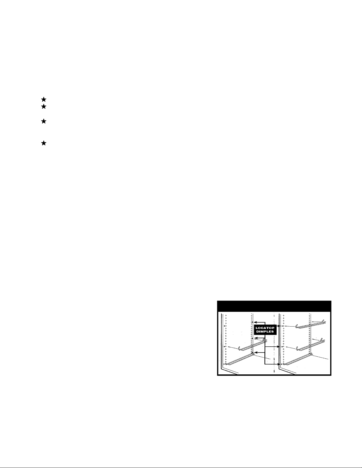
Make certain that the wire shelf supports have been
properly installed. Improperly spaced shelves may
affect air flow circulation within the cabinet interior
leading to “hot” or “cold” spots. As shown in Figure 1,
supports attach to the airflow (side) panels beginning
with the bottom holes in each airflow panel (left and right
side of cabinet). Small indentations (dimples) on the
airflow panels indicate the correct placement holes for
each wire shelf support.
equipped with other types of shelf supports; please
contact the BevLes factory with any questions on
shelf support installation.
NOTE: Some models may be
Figure 1
WARNING:
Step 4.
Step 5.
Push power switch to “ON” position. The digital display will light and show the current cabinet
temperature. A red LED light (located in the upper left corner of the display) will be displayed anytime
the cabinet temperature falls below the set temperature.
After five minutes, check the digital display and the air flow inside the cabinet to be sure that it is
heating properly. As a point of reference, most “empty” full size cabinets will reach their set
temperatures within approximately 30 minutes.
5

Your BevLes Hot Holding Cabinet features a 24-hour mechanical Timer to allow for automatic operation.
The Timer and a Timer ON-OFF switch are located behind the 3¾” x 6” door at the right of the black power
switch near the top of thecabinet. To open the door, turn the black knob counterclockwise untilyou can slide
the door up about ½ inch and then lift the door out and upward.
TO SET TIMER (See Figure 2)
Step 1.
Step 2.
Step 3.
Step 4.
Access the timer behind the sliding door next to the main power
switch near the top of the BevLes cabinet.
Activate the automatic ON/OFF Timer by toggling the switch to
the “ON” position. (NOTE: the switch is not shown in diagram - it
is located to the left of the Timer.)
Determine when you want the BevLes cabinet to automatically
turn on and turn off. Remove the RED TAB and replace it in the
slot when you want the BevLes cabinet to be turned . Press
down to attach the TAB to the Timer. Remove the BLACK TAB
and replace it in the slot when you want the BevLes cabinet to be
turned . Press down to attach the TAB to the Timer.
Turn the dial clockwise until the TIME ARROW (B) (the black
arrow located in the center of the Timer) is pointing at the correct
time of day.
Be sure that the main heated cabinet power switch (black) remains in the “ON” position.Step 5.
OFF
ON
Figure 2
Note: For unscheduled ON/OFF operation of the cabinet the Manual Knob may be used to
override the timer’s ON/OFF mode settings.
IN CASE OF POWER LOSS, RESET TIMER AS DESCRIBED IN STEP 4.
3. CLEANING
Step 1.
Step 2. WARNING: Always unplug the cabinet before
Step 3. CAUTION: At least two people should do the
Step 4.
Step 5.
Step 6.
Step 7.
IF YOU HAVE ANY QUESTIONS REGARDING THE INSTALLATION OR OPERATION OF YOUR
BEVLES HOT HOLDING CABINET, REVIEW THIS MANUAL AND THEN CALL THE BEVLES FACTORY
CUSTOMER SERVICE SUPPORT HOTLINE:
Push power switch to OFF position.
Unplug power cord from power source.
dismantling or cleaning.
If needed, remove the top mounted heating unit.
lifting to avoid possibleinjury.
Open door(s) to 90° position.
Remove the wire shelf supports.
Remove the airflow (side) panels by carefully lifting each panel and tilting the bottom toward the
center of the cabinet.
damage or bending may makere-installation difficult.
Clean all parts thoroughly with soapy water and soft cloths or sponges. Never use steel wool or
caustic cleaning compounds.
WARNING: Avoid splashing water or any other liquid into the top mounted heating unit to
prevent possible damage to electricalcomponents.
CAUTION: Use care when handling the airflow (side) panels. Any
BEVLES 800/441-1601
6

32.344
4. SPECIFICATIONS
22.507
39.314
4.977
82.221
72.882
7

5. TROUBLESHOOTING GUIDE
SYMPTOM MOST LIKELY CAUSE SOLUTION
Digital Controller displays 2 dots
at bottom of display (Open
Sensor Indicator Lights, See
Diagram).
Digital Controller Displays Temp.
Between 165-180 ºF.
VERIFY: 1)Actual cabinet temp. is
low, 2)There IS NO air movement
from left side air duct.
Digital Controller Displays a
Temp. Between 200-240 ºF.
VERIFY: 1)Actual cabinet temp. is
between 200-240 ºF, 2)Heater
Indictor Light is OFF, 3)There IS
air movement from left side air
duct.
IS
Temperature Sensor has
failed or the connector is
loose or not plugged in.
Main Blower (fan) has
failed.
The Relay has failed in
the Closed position (will
not turn the heater off).
Call the BevLes Technical Service
Department to verify symptoms and
for a possible solution involving
removing the Control Module (If
further repairs are required under
warranty obtain your Authorization
Number for repairs).
Call the BevLes Technical Service
Department to verify symptoms and if
under warranty to obtain your
Authorization Number for repairs.
Call the BevLes Technical Service
Department to verify symptoms and if
under warranty to obtain your
Authorization Number for repairs.
Digital Controller Displays a
Temp. Less Than 100 ºF.
VERIFY: 1)Actual cabinet temp. is
between 70-100 ºF, 2)Heater
Indicator Light is ON, 3)There IS
movement from left side air duct.
Digital Controller is Blank
VERIFY: 1)Power switch is on,
2)Unit is plugged in appropriate
outlet, 3)There is air movement
from left side air duct.
Digital Controller is Blank
VERIFY: 1)Power switch is on,
2)Unit is plugged in appropriate
outlet, 3)There IS NO air
movement from left side air duct.
Air
The Relay has failed in
the Open position (will not
turn the heater on).
The Transformer and/or
Temperature Controller
has failed.
1)Power Cord not
plugged in, 2)Circuit
Breaker may have
tripped, 3)Outlet may be
damaged, 4)Power cord
plug could be damaged,
5)Timer is being used
(Timer Bypass switch in
ON Position) but the time
or trippers are indicating
the wrong time, 6)Power
switch may have failed.
Call the BevLes Technical Service
Department to verify symptoms and if
under warranty to obtain your
Authorization Number for repairs.
Call the BevLes Technical Service
Department to verify symptoms and if
under warranty to obtain your
Authorization Number for repairs.
1)Verify Power Cord is plugged in
appropriate outlet, 2)Verify Circuit
Breaker is not tripped, 3)Verify Outlet
is functioning properly (unplug BevLes
unit, plug a known working appliance
into outlet with same voltage and turn
on, plug BevLes unit back into outlet),
4)Verify Plug is not damaged, 5)Set
the correct time and manually trip
timer to on position if necessary,
6)Call the BevLes Technical Service
Department to verify symptoms and if
under warranty to obtain your
Authorization Number for repairs.
Heat Indicator Light
Open Sensor Indicator Lights
DIGITAL
CONTROLLER
DISPLAY
8

6. Preventive Maintenance (
A minimum clearance of 4” should be maintained at the sides, back and top of all CS82-CH8 models. This
will allow for proper operation of all fan blowers and cooling fans. No objects should be placed on top of the
cabinet. The cabinet shouldbe level with all hex feet of the 6” legs firmly adjusted. The CS36 model should
have a minimum of 2” to 4” clearance at the sides and back.
The following should be performed at least once every three to six months:
POWER CORD SHOULD ALWAYS BE DISCONNECTED FROM POWER SOURCE BEFORE
PERFORMING ANY PREVENTIVE MAINTENANCE ON THE TOP MOUNTED HEATING UNIT.
All models have louver openings at the left front side corner of the Top Mounted Heating Unit.
These openings must remain open so that ambient air can circulate past the control module (cooling
the electrical components inside the Front Panel). On the CS82 model there are additional louver
openings located on the top of the Top Mounted Heating Unit that must also remain open to
prevent the main internal fan blower (motor) assembly from over heating. The CS36 model has
additional louver openings located in the rear panel (back) of the Top Mounted Heating Unit that
must also remain open to prevent it’s main internal fan blower (motor) assembly from over heating.
Use a slotted screwdriver to remove the four screws from the corners of the front Panel of the Control
Module. Carefully lift out the Control Module (you do not have to disconnect any wires at the rear of
the Control Module) and place it on top of the cabinet. Inspect the axial cooling fan located in the left
front corner of the Top Mounted Heating Unit, and make certain that it is clean and free of any dirt
or grease build-up. Next, inspect the left end of the Control Module (where the cooling fan blows) for
any dirt or grease build-up. You can use a damp cloth and mild cleanser to clean this surface
NOT get any liquid in the area behind the Control Module (where the 12 connector terminal
block is mounted).
Unit and secure with the four slotted screws. On CS36 model there a second axial cooling fan
located inside the rear panel (back) of the Top Mounted Heating Unit. It is extremely important that
this cooling fan also remain clean and free of any dirt or grease build-up.
After cleaning, place the Control Module back into the Top Mounted Heating
For Taco Bell Hot Holding Cabinet Models: CS82-CH8, CS36-CH3)
DO
Visually inspect the magnetic door gaskets for any damage (dirt or grease, tears, exposed magnet,
etc.). Clean or replace if needed.
Visually inspect power cord and 20Amp molded plug for any excessive wear ordamage.
On CS82 model, check 6” legs to be certain that all hex feet are properly adjusted and making firm
contact with the floor. (Check to see that cabinet is level). On CS36 model check to see that the
casters are free of any dirt or debris, and the brakes are in locked position when cabinet is in use.
Visually inspect the door latch and hinges to verify that they are securely attached to the door and
cabinet. Check attachment screws for snugness. If any screws are loose or missing they must be
placed back to correct position. Use a permanent “high strength threadlocker” to re-install screws,
or order replacement screws (with a threadlock patch) from .
Inspect to see that airflow side panels are properly mounted on the inner side walls of the cabinet.
Check to see that the Top Mounted Heating Unit is properly seated on the cabinet. This can be
easily verified by removing the left and right “top” airflow side panels and visually inspecting the fit of
the Top Mounted Heating Unit into the cabinet frame. Also, make certain that the wire shelf
supports (8 sets) are located in the proper positions for uniform airflow and temperature distribution.
Small indentations (dimples) on the airflow side panels indicate the correct placementholes for each
wire shelf support. The first wire shelf support should be located inthe bottom hole of the airflow side
panel (next to the base of the cabinet). The second is located 7 ½” above the first, and this continues
up the side of the cabinet.
BevLes (800)
733-2203
9

10
SENSOR
PROBE
TIMER BOX
P2
28 29 30
WHT
GRN
BLK
31
32
CONTROL
32
1
BLK
31
2
WHT
33
34
WHT WHT
35 38
WHT
ENCL
P3
P4
1
4
2
5
36
3
4
BRN
BRN
BLK
37
7. WIRING DIAGRAMS (1 of 3)
TACO BELL TOP MODULE
BLOWER
41
36
M
WHT
BLK
WHT
39
40
GRN
WHT
BLK
41
30
28
34
BRN
37
WHT
40
BLK
39
GRN
29
TB2
1
2
3
4
5
6
120V
AC INPUT
48 47 46
45
GRN
WHT
HEATING
ELEMENT
44
BLK
FAN
WHT
WHT
33
47
BLK
BRN
38
46
BLK
WHT
WHT
BLK
43
42
BLK
FAN POWER
CORD
45
44
42
BLK BLK
36 35
BLK
43

11
TIMER BOX
J1
S2
321
P1
WIRING DIAGRAMS (2 of 3)
TACO BELL CONTROL PANEL
WHT
WHT
6
7
5
2
1
24
25 23
BRN
WHT
XFORMER
WHT
7
6
LT
BRN
BRN
22
27
RELAY
1
423
89
WHT
WHT
WHT
WHT
5
4
J2
YEL
BLU
10
LT
13
12
10
11
BRN
BRN
1
BLK
12
GRN
BLK
WHT
GRN
123
3
WHT
15
16
14
J3
1
2365
4
WHT
WHT
WHT
BLK
BRN
4
18
17
BLK
BRN
TB1
15
18
17
1
2
3
4
14
5
19
6
16
BRN
LT
21
BRN
20
13
11
LT
WHT
5
876
BRN
43
27
BRN
26
WHT
WHT
22
2
BRN
ENCLOSURE BOX
BRN
FRONT
PANEL
S1
1
BRN
2
BLU
YEL
CONTROLLER
3
4
WHT
8
WHT
9
DIGITAL

WIRING DIAGRAMS (3 of 3)
TACO BELL FRONT PANEL ENCLOSURE
12
120V
INPUT
HEATING
ELEMENT
WHT
47
BLK
46
GRN
48
COOLING
FAN
FAN POWER CORD
M
WHT
BLK
47
BLK
BLK
44
BRN
BRN
WHT
GRN
33
34
35
36
37
38
BLK
2834
30
P4 J3
11
22
33
44
55
66
P2
11
22
33
16
15
19
18
17
J1
P1
TB1
1
15
18
17
1414
19
16
2,22,23,24
11,20
1
2
3
S1 S2
2
1
2
1
21
2
27
3
4
5
6
13
2
WHT
BLOWER
MOTOR
BLK
39
M
40
GRN
GRN
WHT
BLK
41
TB2
GND
1
2
3
4
5
6
GND
WHT
45
33
38
BLK
41
WHT
BRN
46
WHT
45
BLK
44
42
43
35
36
WHT
WHT
30
BLK
28
WHT
BRN
37
WHT
40
BLK
39
GRN
29 29
WHT
WHT
BLK
DIGITAL CONTROL
SENSOR
PROBE
WHT
BLK
32
P3 J2
4
11
31
3
22
33
897 6
5
3 4
20,21,25,26
20
252626 7
23
24
11
2
22
22
2
1
12
3
13
7654321
XFORMER
15
2
6
3
7
6
5
4
8
SS RELAY
12
27
4
9 8
3
23
25
24
22
44

13
MAIN CABINET
3
3
2
35
35
1
37
37
49
131
131
2
34
34
1
48
8. PARTS LIST & EXPLODED VIEW
6
6
24
1
1
1
1
5
5
1
14
14
4
23
23
1
24
4
48
48
66
47
47
16
4
4
10
10
4
8
8
1
12
12
2
27
27
2
48
66
26
26
8
25
25
4
1
11
11
4
9
9
1
20
20
19
16
18
18
1
19
34
40
40
1
42
42
4
21
49
49
2
21
16
28
28
1
29
29
17
17
1
1
22
22
1
36
36
39
39
1
43
43
4
31
31
1
38
33
33
29
32
32
38
1
1
1
44
44
4
45
45
4
30
41
41
16
30
20
46
46
2
16
16
1
15
100
13
13
15
4
7
7
1
2
2
1

PARTS LIST & EXPLODED VIEW (Continued)
14
Top Module
100
87
69
104
1
104
85
85
8
103
103
1
105
105
2
106
106
1
93
1
112
1
112
114
114
113
1
1
113
86
110
110
86
1
1
111
111
97
152
152
1
95
96
95
2
Door
53
53
2
57
Assembly
130
37
55
65
51
65
1
119
119
78
129
129
4
128
50
15
15
100
72
72
1
63
63
1
60
60
2
59
59
2
19
34
19
1
107
107
3
132
132
1
133
133
1
78
120
1
120
5
54
91
94
58
147
123
123
33
33
29
1
140
140
1
122
136
136
1
81
81
9
80
80
1
89
83
1
1
139
82
84
84
2
88
88
1
102
99
99
109
1
109
1
139
1
98
1
98
126
126
127
127
79
79
9
66
66
73
4
1
1
64
64
67
67
1
1
107
107
11
61
61
1
68
2
68
74
62
62
1
85
85
8
120
71
70
1
70
74
1
75
75
1
77
77
4
115
115
1
116
4
116
71
5
120
1
117
117
1
118
1
118
90
90
1
96
2
135
83
92
2
92
108
124
101
101
134
81
9
81
76
10
76
121
1
121
125
125
1

Item P/N Description Quan
747668
15
1
2
3
4
5
6
7
8
9
10
11
12
13
14
15
16
17
18
19
20
21
22
23
24
25
26
27
28
29
30
31
32
33
34
35
36
37
38
39
40
41
42
43
44
45
46
47
48
49
50
51
747669
784820
747670
784772
784776
747685
747686
747663
760030
760516
760512
760518
742040
8353600
747664
747665
747662
8353100
740565
770169
747666
747681
8353200
85196-00
8205500
760031
747661
747682
8211100
747695
747687
8175900
742128
747678
747676
770628
747677
747680
784780
8507900
784696
8507600
85082-00
8425200
742104
745747
770084
742172
784692
747691
BACK, OUTER
SIDE, OUTER, RIGHT
GASKET, MAGNETIC 32-2/5 X 28-1/8
SIDE, OUTER, LEFT
DUCT WRAP, 48 X 70 X 1.5 - CAB
DUCT WRAP, 21 X 70 X 1.5 - CAB
HINGE, RIGHT SUPPORT
HINGE, LEFT SUPPORT WELDMENT
INNER SIDE, LEFT
SHIM, SIDE, INNER
STRIP,BACKING .50 X .875 X 16.25
STRIP,BACKING .50 X .875 X 30.75
STRIP,BACKING .50 X .875 X 30.00
SUPPORT, BUTTON
RIVET, POP 3/16 FLUSH BREAK
INNER SIDE, RIGHT
BACK, INNER
BASE, INNER
RIVNUT, 10-32 THIN HEAD
BRACKET, HOOK, AIR DUCT
SCREW, SHT METAL, #10 X 1/2, Z
HEADER BAR, CENTER
COVER, HEADER BAR, CENTER
RIVNUT, 1/4-20 THIN HEAD
WASHER .75 X .281
SCREW, 1/4-20 X 1/2 TR HD
SHIM, CENTER INNER SIDE
HEADER BAR, TOP
COVER, HEADER BAR, TOP
SCREW, MACH 1/4-20 X 3/4
WELDMENT, GASKET RETAINER
GASKET RETAINER, OUTER, BOTTOM
SCREW, 10-32 X 1/2 TR HD,SS
GASKET RETAINER, OUTER, CENTER
GASKET RETAINER, OUTER, TOP
GASKET RETAINER, RIGHT, OUTER
12-24 X 1/2 TR HD PH W/PATCH
GASKET RETAINER, LEFT, OUTER
BASE, OUTER
DUCT WRAP, 18 X 29 1.5 - BASE
WASHER, LOCK, INT, 1/4, Z
LEG, ADJUSTABLE
WASHER, FLAT 1/4"
WASHER, LOCK, 1/4, ASME B18.21.1
NUT, HEX, 1/4-20 SS
AIR DUCT, BOTTOM
BRACKET,AIR DUCT
RIVET, SOFT, 5/16, 566PC/LB
AIR DUCT, TOP
HINGE - CAM RISE CHROME
DOOR, OUTER, TOP (TYPE B)
Item P/N Description Quan
1
1
2
1
1
1
1
1
1
4
4
2
4
4
100
1
1
1
34
16
16
1
1
4
4
8
2
1
1
20
1
1
29
1
1
1
49
1
1
1
16
4
4
4
4
2
16
66
2
4
1
52*
53
54
55
56*
57
58
59
60
61
62
63
64
65
66
67
68
69
70
71
72
73
74
75
76
77
78
79
80
81
82
83
84
85
86
87
88
89
90
91
92
93
94
95
96
97
98
99
100
101
102
720277
784768
8353000
784711
747693
720275
741984
741948
742076
742084
760484
742080
784832
742180
742260
741952
782144
8400100
742248
788005
741956
8967200
742000
782208
8105800
784724
742004
770344
742168
770536
742012
784680
770709
8408300
742164
747684
747683
784700
782149
782151
784548
784700
81108-00
8500700
8402900
89784-00
742024
742244
81778-00
742028
760488
DOOR, WELDM'T - TB BOTTOM/INNER
DUCT WRAP 29.75 X 33 X 1.50
POP RIVET
LATCH, MAGNETIC
DOOR, BOTTOM, OUTER
DOOR, WELDM'T - TB TOP/INNER
SKIN, OUTER TOP
CHANNEL, SIDE, TOP
SIDE, INNER, TOP
FRONT, INNER TOP
INSULATOR, HEATER TERMINAL
INNER, REAR TOP
URETHANE, 15.44 X 32 X 2
DEFLECTOR, AIR
COVER, INSULATION
CHANNEL, FRONT
TERMINAL BLOCK
NUT, HEX KEPS, #6-32
CLAMP,TIMER WIRE
BUSHING, SNAP 1/4 " BLACK NYLON
CHANNEL, REAR
BUSHING, SNAP .5 HOLE NYLON
WELDMENT, SLIDE, WATER PAN
THERMOSTAT
SCREW, PH, 6-32x3/8, S/S
CERAMIC INSULATOR
COVER, MOTOR
NUT,TINNERMAN CLIP
PANEL, REAR
TR HD PH SMS 10 X 1/2 SS
MOUNTING, COOLING FAN
FAN, AXIAL
SCREW, RD HD SL #8-32 X 2 ZN
#8-32 HEX NUT, KEPS, NI
CONTROL PANEL
ENCLOSURE, ELECTRICAL
ENCLOSURE, TIMER
BLACK CONNECTOR
PLUG, 4 PIN
CLAMP, "C"
MOUNTING ADAPTER CONN- RED
WIRE SET, TBCM
M/S TR HD PH 6-32x1"
LOCK WASHER EXT #6
NUT, HEX, 6-32 SS
BUSHING, 7/8 SNAP, HEYCO
TIMER, BRACKET
CLAMP,TIMER CORD
M/S, TR HD PH, 10-32 X 3/4 S/S
BRACKET, BRACKET
INSULATOR, TIMER, SWITCH TERMINALS
Item P/N Description Quan
1
2
48
2
1
1
1
2
2
1
1
1
1
1
4
1
2
11
1
1
1
4
1
1
10
4
1
9
1
9
1
1
2
8
1
1
1
1
1
2
2
1
2
2
2
2
1
1
7
1
1
*NOT SHOWN
16

9. BEVLES COMPANY LIMITED WARRANTY
729 Third Avenue * Dallas, TX 75226
Phone: +1 (214) 421-7366 Fax: +1 (214) 565-0976
1. Bevles warrants to the original purchaser that on the date the equipment is shipped (sold), it will be
free of defects in materials or workmanship. Bevles will, at its discretion, repair or replace, during
the warranty period printed below, any part that has a defect in material or workmanship that was
present when the product shipped from Bevles, and which manifests itself during the warranty
periodunder nomal use and service.
!
Parts:Two*years from dateof originalshipmentfrom the Bevles factory.
!
Labor:One** year
* Air Circulation BlowerAssemblies(motors) and Power Switchesshall be one year from date of
originalshipment.
CalrodAir Heating Elementsshallbethreeyearsfromdateoforiginalshipment.
fromdate of originalshipment from the Bevlesfactory.
** All electrical components120days
2. Bevles must be contacted, and pre-approval must be issued by the Bevles factory prior to any type
of service being performed. Bevles assumes no responsibility for any charges that were not expressly
authorizedby the Bevles factory,or for any chargesthatexceed,in Bevlessolejudgement, normal and
customaryamounts.
3. Bevles will payUPS Ground charges for any part that has a defectin material or workmanship that was
present when the product shipped from Bevles, and which manifests itself during the of the
warrantyperiod under normal use and service.All warranty replacement parts will ship F.O.B.Bevles
factory,Chino,CA91710.
4. This warranty shall be void in its entirety if any abuse of, misuse of, alteration/modification of or
improper maintenance of original product occurs. If, at any time a claim is reported to Bevles, the
purchaseris delinquent in paymentfortheproduct,warrantywill not apply.
5. BuyersRemedies-If a Bevles product fails due to a defect in material or workmanship in conformity
withthewarrantiesin paragraph one, buyer shall notify Bevlesof such failurewithinareasonabletime,
but in no event beyond fifteen (15) days of such discovery of defect in material or workmanship.
Bevlesshallprovide, in its sole discretion,either the repair or replacementof any defective or any non-
conforming part. Bevles specifically disavows any other representation, warranty or liability relating
tothecontinueduse of the product.
6 Exclusion of consequential and incidental damages-In no event shall Bevles be liable for any
incidental, special, indirect, or consequential damages, whether resulting from non-delivery or from
the use, misuse, or inability to use the product, or from defects in the product, or from
Bevlesown negligence or other tort. This exclusion applies regardless of whether such damages are
soughtfor breach of warranty,breach of contract, negligence,orstrictliabilityintortorunderanyother
legaltheory.
fromdate of originalshipment.
first year
7. Disclaimer of warranties-The warranties contained in paragraph one above are the exclusive
warranties given by Bevles and supersede any prior, contrary, or additional representations,
whether oral or written. Bevles hereby disclaims and excludes all other warranties-whether
expressed, implied, or statutory-including any warranty of merchantability, any warranty of
fitness for a particular purpose, and any implied warranties otherwise arising from course of
dealingor usage of trade.
4/02
16
 Loading...