

Page 1
SERVICE &
INSTALLATION
MANUAL
Modular
Merchandiser
51-0195-01
1/2003
CARRIER COMMERCIAL REFRIGERATION, INC.
Providing BEVERAGE-AIR • FRIGIDAIRE • KELVINATOR • UNIVERSAL NOLIN Products/Services
Page 2

If additional information is necessary, call the factory.
Our toll free number is 1-800-684-1199.Technical assis-
tance engineers are willing to assist you in any way possible. Office hours are from 8:00 a.m. to 5:30 p.m., Eastern
Standard Time.
Important information is contained in this manual which should
be retained in a convenient location for future reference.
Information in this manual is subject to change without notice.
MODEL DESIGNATION INFORMATION
115V, 60HZ
PART # MODEL # DATA PLATE STYLE
52-1029-01 CRPD3 CRPD3 MEDIUM TEMP, CURVED
52-1029-02 CRPD4 CRPD4 MEDIUM TEMP, CURVED
52-1029-05 CRPD6 CRPD6 MEDIUM TEMP, CURVED
52-1030-01 RPD3 RPD3 MEDIUM TEM, STRAIGHT
52-1030-02 RPD4 RPD4 MEDIUM TEMP, STRAIGHT
52-1030-04 RPD4PT RPD4 MEDIUM TEMP, STRAIGHT
52-1030-05 RPD6 RPD6 MEDIUM TEMP, STRAIGHT
52-1031-01 CDPD3 CDPD3 DRY, NON REF, CURVED
52-1031-02 CDPD4 CDPD4 DRY, NON REF, CURVED
52-1031-05 CDPD6 CDPD6 DRY, NON REF, CURVED
52-1032-01 DPD3 DPD3 DRY, NON REF, STRAIGHT
52-1032-02 DPD4 DPD4 DRY, NON REF, STRAIGHT
52-1032-05 DPD6 DPD6 DRY, NON REF, STRAIGHT
52-1033-01 CFPD3 CFPD3 LOW TEMP, CUR VED
52-1033-02 CFPD4 CFPD4 LOW TEMP, CUR VED
52-1034-01 FPD3 FPD3 LOW TEMP, STRAIGHT
52-1034-02 FPD4 FPD4 LOW TEMP, STRAIGHT
52-1035-01 COHM3 COHM3 MEDIUM, OPEN, CURVED
52-1035-02 COHM4 COHM4 MEDIUM, OPEN, CURVED
52-1035-03 COHM6 COHM6 MEDIUM, OPEN, CURVED
52-1036-01 OHM3 OHM3 MEDIUM, OPEN, STRAIGHT
52-1036-02 OHM4 OHM4 MEDIUM, OPEN, STRAIGHT
52-1036-03 OHM6 OHM6 MEDIUM, OPEN, STRAIGHT
52-1036-04 OHM3 BLACK OHM3 MEDIUM, OPEN, STRAIGHT
52-1047-02 BRD52 BRD52 LOW TEMP, STRAIGHT
EXPORT 220V, 50HZ
PART # MODEL # DATA PLATE STYLE
52-1033-05 ECFPD4 ECFPD4 LOW TEMP, CUR VED
52-1034-05 EFPD4 EFPD4 LOW TEMP, STRAIGHT
52-1047-06 EBRD52 EBRD52 LOW TEMP, SRAIGHT
EXPORT 220V, 60HZ
PART # MODEL # DATA PLATE STYLE
52-1033-03 KCFPD4 KCFPD4 LOW TEMP, CUR VED
52-1033-04 KCFPD4C KCFPD4 LOW TEMP, CUR VED
52-1034-03 KFPD4 KFPD4 LOW TEMP, STRAIGHT
52-1034-04 KFPD4C KFPD4 LOW TEMP, STRAIGHT
52-1047-04 KBRD52 KBRD52 LOW TEMP, STRAIGHT
Manual effective for models produced January,2003.
Starting serial number 6701822.
Page 3

MED TEMP LOW TEMP
Temperature Range 32°F to 60°F 0°F to -15°F
Insulation 23⁄16" Foam in Place 2 5⁄16" Foam in Place
Compressor Size 1/2 H.P. 1 H.P.
Condenser Type Fin & Tube Fin & Tube
Evaporator T ype Fin & Tube Slow Moving Air Fin & Tube Slow Moving Air
Refrigerant Type 404A 404A
Defrost System On Demand On Demand
Electrical Specs. 115/60/1 115/60/1
NSF NSF 1 NSF 1
Shelves
Shelves, Epoxy Coated, Bracket Supported Shelves, Epoxy Coated, Bracket Supported
UL & CSA Listing Yes Yes
MODULAR MERCHANDISER 1
SPECIFICATIONS - DISPLAY CABINETS
DIMENSION DRAWINGS - COHM & OHM
DIMENSION DRAWINGS - FPD, CFPD, RPD & CRPD
Page 4

An Important Message for Installers
and Operators
These instructions include information which is intended to assure the operator of correct installation, operation and service. Before attempting installation, adjustment or maintenance be certain of the following:
1.That you have read and fully understand
the instructions.
2. That you have all tools required and are trained to
use them.
3.That you have met all installation and usage restric-
tions and are familiar with the functions and operation of the unit.
4.That you follow all instructions exactly as given.
All fittings, measurements, procedures and recommendations are significant. Substitutions and approximations must be avoided.Improper handling, maintenance,
installation and adjustment, or service attempted by
anyone other than a qualified technician, may void the
future warranty claims and cause damage to the unit
and/or result in injury to the operator and/or bystanders.
Important Information Is contained In these
instructions which should be retained in a
convenient location for future reference .
Record for Service
Model No.
Serial No.
Invoice Date
Start-up Date
Telephone for Service
BE SURE TO INSPECT CABINET FOR SHIPPING
DAMAGE BEFORE AND AFTER UNCRATING IT.
HANDLING & INSTALLATION
Inspecting for Damage
NOTE: The transportation company or other parties
involv ed in the shipment are responsible f or loss and/or
damage.When direct delivery was made by the trans-
portation company, follow the procedure as outlined in
the following steps:Always make an Inspection before
and after uncrating.Inspect the uncrated unit(s) before
locating (preferably at the point of unloading by the
transportation company.) You may leave the skid on
the unit for ease of locating it later.
a. Damaged cartons or containers - If these are damaged in any way, open them and inspect the contents
in the driver’s presence.
b. Have the driver note the nature and extent of the
damage on the freight bill.
c. Notify the transportation company’s office to request
an inspection. Carrier claim policies usually require
inspections to be made within 15 days of delivery.
d. Always use care when removing shipping tape,
blocks, pads, hardware, or other materials. Retain all
crate and packaging material until you are satisfied
that the unit is completely operational.
e. Contact factory if technical assistance is required.
f. If damage is noticed (whether before or after uncrat-
ing the unit) the following claim procedure must be
completed.
Inspecting for Shortages
NOTE: Refer to the “Inspecting for Damage” instructions and follow the procedure described.
a. Check the number of cartons and/or containers
delivered with the quantity shown on your receipt.
b. If the quantities are not the same, have the driver
note the shortage and file your claim accordingly.
Filing Claims
a. File a claim for loss or damage at once with the
transportation company for:
1) A cash adjustment
2) Repairs
3) Replacement
b.When filing y our claim, retain all pac kaging materials
and receipts.
Handling the Cabinet
The refrigeration system of the cabinet is designed to
operate with the cabinet located on a flat surface.
Avoid tilting the cabinet more than 30° to any side. If
the cabinet must be tilted on an angle for handling or
moving purposes, allow it to sit in an upright position
20 to 30 minutes prior to plugging it in and starting the
cooling of the storage compartment.
GENERAL INFORMATION
2 MODULAR MERCHANDISER
Page 5

Removing the Skid
Remove the four (4) bolts securing the cabinet to four
(4) angle brackets attached to the skid. Remove the
skid bolts and angle brackets.Carefully slide the cabinet off the skid onto the floor.
Locating the Cabinet
This model is a display cabinet and should be positioned to expose the illuminated displays to customers
in the store and provide a clear space behind for the
person serving.
Select a location where you are sure that the cabinet
won’t be exposed to heat sources such as sun through
a window, store heating or cooling ducts, exhausts
from other cabinets, etc. Make sure there is adequate
space on the serving side for loading cabinet and serving efficiently.
DO NOT DRILL HOLES IN THE CABINET WALLS.
THIS WILL VOID THE W ARRANTY
a.The cabinet must be installed on a sturdy and solid,
level floor.
b. The cabinet should be installed in a protected, dr y,
and well-ventilated area, away from any heat source.
Leveling the Cabinet
Level the cabinet using a spirit level on top. Level front
to back and side to side to assure a quiet operation
and satisfactory door and drain operation. Doors are
self-closing (sliding door models only) when cabinet is
level. Shim under the cabinet base as necessary to
assure a level cabinet. To meet NSF requirements,
these cabinets must be sealed to the floor with an NSF
listed or FDA approved sealant.
Setting up the Cabinet
Cabinets are shipped with the adjustable shelf mounting brackets in place. Shelving is also supplied with
the cabinet.
Shipping material (cardboard, paper, plastic, ties,
etc.) should be removed from shelving and the
product area.
CAUTION: Make sure that the shelf light plugs or
receptacle covers are completely inserted into the light
socket receptacles.This prev ents electrical arcing and/
or possible equipment damage.
MODULAR MERCHANDISER 3
Grounding Instructions
This appliance is equipped with a three-prong (grounding) plug for your protection against shock hazards.The appliance should be plugged directly into a proper ly grounded three prong receptacle.
Where a two-prong wall receptacle is encountered, it must be replaced with a properly grounded threeprong receptacle in accordance with the National Electrical Code and local codes and ordinances.The
work must be done by a licensed electrician (cabinet should be on a dedicated circuit unto itself.Refer
to serial data for correct circuit ampacity).
20 Amp
15 Amp
15 Amp
20 Amp
GENERAL INFORMATION-cont.
Page 6
Power Supply Switch
NOTE:When ser vicing or cleaning supply power must
be turned off.The power supply switch is located at the
rear of each cabinet behind the lower rear grill. The
switch is incorporated into the electrical box assembly.
Light Switch-Auxiliary Outlet
The light switch is located at the rear of each cabinet
(when applicable) just above the unit compartment
opening on the right hand side.
The auxiliary outlet is provided to power an external
sign scale (when applicable).
These cabinets utilize a microprocessor control to
manage both cavity temperature and defrost functions.
Cabinet OperationRefrigeration Mode
Upon setting the cabinet in it’s final location, turn
power supply on. The cabinet display should be indicating the cabinet temperature.There is a three minute
time delay sequence built in each time the supply
power is lost (compressor circuit). Evaporator fan
starts and lights come on (medium temp models).
Three minutes later the compressor starts. On low
temp models the evaporator fan delays until the evaporator coil reaches 28°F.
The display located on the lower front panel has several functions,
Display cabinet temperature
Change cavity set point temperature
NOTE: ON MED TEMP CABINETS DO
NOT SET BELOW 33°F.
Display service interface. Only qualified service personnel should activate this function.
Defrost Mode
This is on a demand basis as needed on both medium
and low temperature models.Defrost can be manually
activated through the display if needed.See below.
High Temp Thermodisc Open 140°F
Close 90°F
Notable points
1. This system utilizes a 3 minute off cycle timer to pre-
vent short cycles.
2. When the system initiates a defrost, the setpoint will
flash on and off until the defrost is terminated and the
cavity reaches the setpoint. At this time the cavity tem-
perature will be displayed as normal.
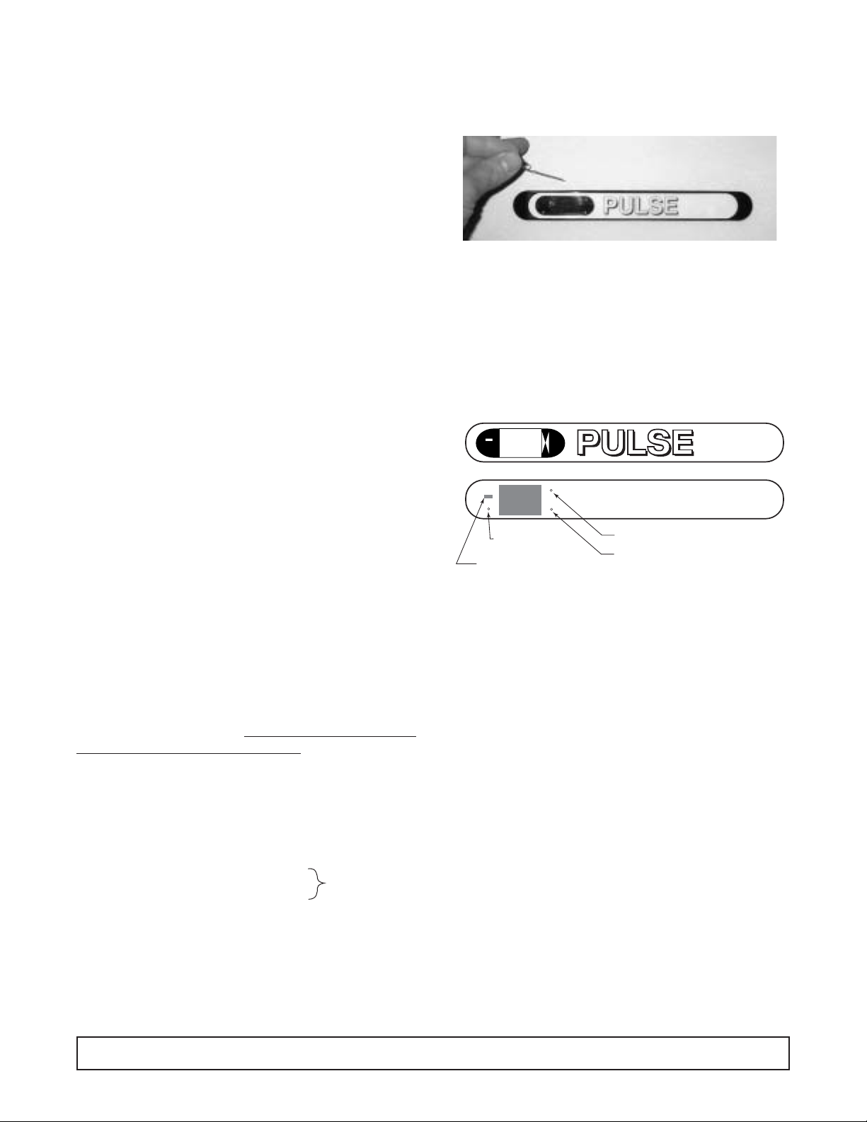
Changing Setpoint
Note: Use a paper clip to access the
function keys.
1. Pressing the top right button(i.e. up key) on the display unit will raise the set point one degree
Fahrenheit. Holding the button down will scroll the
adjustment.
2. Pressing the lower right button(i.e.down key) on the
display unit will lower the set point one degree
Fahrenheit.
The Service Interface and
the Service Menu
(Refer to Pulse Service Manual 51-2484-00 for complete
service information.)
The service menu offers the service technician direct
control of the components of the system. This allows the
technician to force the system into a defrost state or the
refrigeration state. This feature also allows the technician to toggle the state in order to analyze separate components of the system (e.g., start kit, compressor,
heaters, etc.).
1. To access the service menu, press and hold the
service key for 2 seconds. The system will enter the
service menu and c0 will alternately flash with evaporator temperature. Code versions 1.5 and earlier do not
display evaporator temperature. This is the top of the
service menu. To exit the service menu, press the service key again at any time.
2. The service menu offers five functions:
Refrigeration state, Defrost state, code revision level
indication, the option to blank the display (code version
1.6 and later), and Celsius or Fahrenheit operation
(code version 1.6 and later).While in the service menu,
4 MODULAR MERCHANDISER
GENERAL INFORMATION-cont.
Low temp
models only
Service
Interface
Indicates T emp .
below 0°F
Setpoint up
Setpoint down
Page 7

the down key serves to scroll the menu and the up key
serves as a toggle to activate and deactivate the function state.
A. To access the functions simply press the down key
to scroll through the menu until the desired function
is reached.The Refr igeration state is the first function and is denoted by an alternating display of c0
and the evaporator temperature. The Defrost state
is the second function and is denoted by a display
of d0.The third function is a passive state and only
indicates which version of code is running. This
function alternately flashes cc and the code version
01 - 99. The fourth function allows the user the
option to blank the display and is denoted by S0.
The fifth and last option allows the user to select
between Fahrenheit and Celsius operation and is
denoted by a C or a F. Continuing to scroll will bring
the user to the top of the menu again where c0 will
be displayed.
B.To activate a function state, simply press the down
key to scroll the menu until the desired function is
reached. Now press the up key. At this point the
chosen function state is toggled from inactive to
active.
C. To force a defrost: First press and hold the
service button to enter the service menu. Then
press the down key until d0 is displayed. Next
press the up key. The heater is now energized
and d1 is displayed.
D. To activate the refrigeration state: (i.e., this turns on
the compressor, condenser fans, and evaporator
fans) First enter the service menu. Press the top
right button.c0 will change to c1.Use this function to
check refrigerant charge and pressures, evaporator
fans, compressor and start components and etc.
E. To deactivate the function state, press the up key
again (i.e., this button toggles the state from active
to inactive and vice versa).
NOTES:a. When an attempt is made to scroll the
menu while a function state is active, the
active function state will automatically
deactivate.This is to prevent the service
technician from simultaneously activating
the Refrigeration state and the Defrost
state. Only one function may be active at
any given time.
b. If no operation is performed within 45
minutes while in the service menu, the
system will automatically exit the service
menu and return to normal refrigeration.
c. If the Defrost state is activated and left
unattended, the service menu will terminate the defrost as normal on evaporator
temperature; otherwise, the defrost will
terminate in 45 minutes. Upon defrost
termination the system will automatically
exit the service menu.
d. When the system exits the service menu,
the compressor will not start for
3 minutes.
e. The off cycle timer is not incorporated in
the service menu so the service technician has direct control of components.
MODULAR MERCHANDISER 5
GENERAL INFORMATION-cont.
Page 8

AMBIENT 70°F 80°F 90°F
Display setting 41° 36° 31° 41° 36° 31° 41° 36° 31°
Cavity Temp.(F) 39° 35° 30° 39° 35° 30° 39° 34° 30°
Suction Pressure (PSIG) 47 41 36 47 42 37 48 43 39
Discharge Pressure (PSIG) 255 245 233 286 276 262 320 309 297
Compressor Amps 5.9 5.6 5.3 6.0 5.7 5.5 6.2 5.9 5.7
Total Refrigeration Amps 7.9 7.5 7.3 8.0 7.7 7.5 8.2 7.8 7.6
ELECTRICAL/REFRIGERATION SPECIFICATIONS
SYSTEM COMPONENTS - RPD4 & CRPD4
SYSTEM PERFORMANCE -
(READINGS AT CUT-OUT)
Compressor Americold
Compressor Model HP 127
Recommended Operating Temp. Range 36° TO 42°
Cabinet V olts 115
Expansion Device 7' x .054 Capillary Tube
Charge Refrig.Type / Oz./ Grams R-404 /24 / 680.4 grams
6 ELECTRICAL/REFRIGERATION SPECIFICATIONS
ELECTRICAL/REFRIGERATION SPECIFICATIONS
SYSTEM COMPONENTS - RPD3,CRPD3,RPD6,CRPD6
SYSTEM PERFORMANCE -
(READINGS AT CUT-OUT)
Compressor Americold
Compressor Model HP 127
Recommended Operating Temp. Range 36°F to 42°F
Cabinet V olts 115
Expansion Device 7' x .054 Capillary Tube
Charge Refrig.Type / Oz./ Grams R-404 / 16 / 453.6 grams
AMBIENT 70°F 80°F 90°F
Display setting 41° 36° 31° 41° 36° 31° 41° 36° 31°
Cavity Temp.(F) 42° 37° 3° 42° 37° 32° 43° 38° 32°
Suction Pressure (PSIG) 47 39 34 47 41 36 51 43 39
Discharge Pressure (PSIG) 249 231 223 281 268 256 317 303 242
Compressor Amps (Each Compressor) 6.1 5.7 5.6 6.3 6.0 5.7 6.5 6.2 6.0
TotalRefrigerationAmps (RPD3, CRPD3) 8.3 7 7 8.5 8.2 7.8 8.6 8.4 8.1
Total Refrigeration Amps (RPD6, CRPD6) 17.0 16.3 15.6 16.6 15.9 15.2 17.5 16.2 15.5
Page 9

AMBIENT 70°F 80°F 90°F
Display setting 41° 36° 31° 41° 36° 31° 41° 36° 31°
Cavity Temp.(F) 43° 37° 34° 43° 40° 35° 44° 41° 39°
Suction Pressure (PSIG) 50 45 41 49 46 43 49 47 40
Discharge Pressure (PSIG) 269 254 247 295 283 283 326 323 304
Compressor Amps 6.2 6.0 5.7 6.3 6.2 6.1 6.5 6.5 5.9
Total Refrigeration Amps 9.0 8.5 8.3 9.1 8.7 8.6 9.3 9.0 8.7
ELECTRICAL/REFRIGERATION SPECIFICATIONS
SYSTEM COMPONENTS - OHM4 & COHM4
SYSTEM PERFORMANCE -
(READINGS AT CUT-OUT)
Compressor Americold
Compressor Model HP 127
Recommended Operating Temp. Range 36° TO 42°
Cabinet V olts 115
Expansion Device 7' x .054 Capillary Tube
Charge Refrig.Type / Oz./ Grams R-404 /25 / 708.7 grams
ELECTRICAL/REFRIGERATION SPECIFICATIONS 7
ELECTRICAL/REFRIGERATION SPECIFICATIONS
SYSTEM COMPONENTS - OHM3,COHM3,OHM6,COHM6
SYSTEM PERFORMANCE -
(READINGS AT CUT-OUT)
Compressor Americold
Compressor Model HP 127
Recommended Operating Temp. Range 36°F to 42°F
Cabinet V olts 115
Expansion Device 7' x .054 Capillary Tube
Charge Refrig.Type / Oz./ Grams R-404 / 18 / 510.3 grams
AMBIENT 70°F 80°F 90°F
Display setting 41° 36° 31° 41° 36° 31° 41° 36° 31°
Cavity Temp.(F) 41° 37° 33° 42° 38° 34° 44° 41° 37°
Suction Pressure (PSIG) 45 43 37 46 44 40 47 46 40
Discharge Pressure (PSIG) 251 245 233 280 271 267 310 307 293
Compressor Amps (Each Compressor) 7.0 6.8 6.5 7.1 7.0 6.8 7.3 7.2 6.9
TotalRefrigerationAmps (OHM3, COHM3) 7.9 7.8 7.4 8.1 7.9 7.7 8.2 8.2 7.8
Total Refrigeration Amps (OHM6, COHM6) 11.6 11.4 11.2 11.7 11.1 11.4 11.6 11.2 11.3
Page 10

ELECTRICAL/REFRIGERATION SPECIFICATIONS
SYSTEM COMPONENTS
SYSTEM PERFORMANCE -
(READINGS AT CUT-OUT)
FPD4 EFPD4 KFPD4
CFPD4 ECFPD4 KCFPD4
BRD52 EBRD52 KBRD52
Compressor Copeland Copeland Copeland
Compressor Model RS80C1ECAA RS80C2ECAZ-250 RS80C2ECAV
Cabinet Volts 115V 60Hz 220V 50Hz 220V 60Hz
Recommended Operating Temp. Range 36° TO 42°
Expansion Device 7' x .049 Capillary Tube
Charge Refrig.Type / Oz./ Grams R-404 /16/ 453.6 grams
AMBIENT 70°F 80°F 90°F
Display setting +5° -5° -15° +5° -5° -15° +5° -5° -15°
Cavity Temp.(F) 6.0° -2° -11° 6.0° -2° -11° 1.0° -2° -12°
Suction Pressure (PSIG) (115V) 10 8 6 12 10 7 14 12 9
Discharge Pressure (PSIG) (115V) 230 228 213 270 263 245 303 291 280
Compressor Amps (115V) 8.4 8.7 8.5 8.8 8.9 8.2 9.1 9.1 8.8
Total Refrigeration Amps (115V) 12.9 13.1 12.8 13.3 13.3 12.5 13.6 13.6 13.1
Suction Pressure (PSIG) (220V) 7.7 7.2 5.7 10.2 9.2 7.1 12.7 11.1 8.7
Discharge Pressure (PSIG) (220V) 211.1 209.0 203.5 245.3 239.6 232.3 281.2 272.5 263.6
Compressor Amps (220V) 5.0 5.0 4.7 5.0 5.2 4.8 5.6 5.4 4.9
Total Refrigeration Amps (220V) 6.1 6.0 5.9 6.3 6.2 5.9 6.5 6.3 6.1
8 ELECTRICAL/REFRIGERATION SPECIFICATIONS
ELECTRICAL/REFRIGERATION SPECIFICATIONS
SYSTEM COMPONENTS - FPD3 & CFPD3
SYSTEM PERFORMANCE -(READINGS AT CUT-OUT)
Compressor Copeland
Compressor Model RS80CIECAA
Recommended Operating Temp. Range 36°F to 42°F
Cabinet V olts 115
Expansion Device 7' x .049 Capillary Tube
Charge Refrig.Type / Oz./ Grams R-404 / 14 / 396.9 grams
AMBIENT 70°F 80°F 90°F
Display setting +5° -5° -15° +5° -5° -15° +5° -5° -15°
Cavity Temp.(F) +5° -3° -13° +5° -3° -13° 6.1° -3° -12°
Suction Pressure (PSIG) 11.2 8.1 5.2 13 10 7.2 15 12 10
Discharge Pressure (PSIG) 262 244 216 296 272 246 334 311 289
Compressor Amps 9.0 8.3 7.7 9.2 8.6 7.8 9.3 8.7 8.3
Total Refrigeration Amps 12.0 11.3 10.7 12.3 11.6 10.9 12.3 11.8 11.3
Page 11

WIRING DIAGRAM 9
WIRING DIAGRAM – COHM3, COHM 4, OHM3, OHM4
HEATER, WATER DISSIPATION
LIGHT
SWITCH
BLACK
BALLAST BOX HARNESS
115 VAC. 60 Hz.-1Ø
15-AMP POWER SUPPLY
N
(L2)
L1
(BLUE)
(BROWN)
WHITE
BLACK
SUPPLY
SWITCH
GREEN
BLACK
BLACK
BLUE (BLACK ON 20W)
BLACK
3
5
4
6
BLACK
BLACK
WHITE
WHITE
WHITE
BLUE
WHITE
BLACK
1
2
BLACK
BLACK
BALLAST
BLACK
WHITE
BLACK
WHITE
WHITE
ORANGE
FUSE
WH
BLACK
PURPLE
RELAY #1
654
123
YELLOW
WHITE WIRES NOT PRESENT
ON 20W BALLAST.
(FOR MODELS WITH LAMP)
BLUE
YELLOW
RELAY #2
BLACK
LED
BLACK
WHITE
PURPLE
ORANGE
BLACK
ORANGE
BLUE
BROWN
RELAY #4RELAY #3
1 2 3 4 5 6 7 8
O
BROWN
WHITE
RED
BLACK
BROWN
BLUE
UPPER LAMP HARNESS
WHITE
BROWN
N
1
2
3
BLUE
MAIN LAMP
S
3
2
1
4
3
2
1
5
4
98
6
7
DISPLAY
DISPLAY HARNESS
PROCESSOR HARNESS
GREEN
BLUE
GRAY
RED
BLACK
GREEN
RED
BLACK
BLACK
WHITE
RUN CAP.
12
3
4
5
6
7
8
9
EVAPORATOR HARNESS
BLACK
BLACK
YELLOW
RED
BLACK
START CAP.
ORANGE
BROWN
BLUE
RED
GRAY
WHITE
EVAPORATOR HARNESS
GREEN
BLACK
BLACK
CONDENSER
FAN MOTOR
YELLOW
COMPRESSOR
HARNESS
BLUE
2
3
1
4
COMPRESSOR
TERMINAL BOX
MOTOR
PROTECTOR
(PTCR)
BLACK
HEATER, ANTI-SWEAT
THERMOSTAT
BLACK
EVAPORATOR
FAN MOTOR
BROWN
DUMMY
PLUG
1
TEMP. SENSOR
EVAPORATOR
2
TEMP. SENSOR
WHITE
RETURN AIR
WIRING DIAGRAM-OPEN, MED-TEMP.
00-0219-00
Page 12

10 WIRING DIAGRAM
WIRING DIAGRAM – CFPD3, CFPD4, FPD3, FPD4, BRD52
LIGHT
SWITCH
BLACK
BALLAST BOX HARNESS
115 VAC. 60 Hz.-1Ø
20-AMP POWER SUPPLY
N
(L2)
L1
(BLUE)
(BROWN)
WHITE
BLACK
SUPPLY
SWITCH
RETURN AIR
1
TEMP. SENSOR
EVAPORATOR
2
TEMP. SENSOR
BROWN
WHITE
EVAPORATOR
FAN MOTOR
BLACK
BLUE
DISPLAY
S
LAMP
LAMP
LAMP
HEATER-GLASS
HEATER-GLASS
PERIMETER
HEATER-LAMP
CHANNEL
C
2
3
R
BLUE
PROTECTOR
COMPRESSOR
TERMINAL BOX
1
S
BLUE
RED
RED
MOTOR
BLUE
HEATER-DOOR
OPENNING
HEATER-DOOR
OPENNING
BLACK
UPPER LAMP HARNESS
BLACK
BLACK
BALLAST
BLACK
3
5
6
1
WHITE
4
2
WHITE
WHITE
BALLAST
WHITE
WHITE
BLACK
BLACK
WHITE
BROWN
GREEN
RED
BLACK
GREEN
RED
BLACK
BLUE
GRAY
BROWN
WHITE
WHITE
BLACK
BLACK
WHITE
WHITE
BLACK
ORANGE
FUSE
WH
BLACK
DUMMY
PLUG
PURPLE
RELAY #1
654
WHITE
RELAY #2
BLACK
LED
BLACK
WHITE
123
YELLOW
ORANGE
PURPLE
ORANGE
YELLOW BROWN
BLUE
12
3
4
5
6
7
8
9
EVAPORATOR HARNESS
WHITE
BLACK
RED
START CAP.
BLUE
RELAY #4RELAY #3
1 2 3 4 5 6 7 8
N
O
BROWN
BROWN
WHITE
BLACK
BLUE
YELLOW
RED
ORANGE
BROWN
BLACK
EVAPORATOR HARNESS
GREEN
BLACK
1
BROWN
2
3
BLUE
3
2
1
4
3
2
1
5
4
6
7
RED
GRAY
WHITE
BLACK
YELLOW
21
98
5
POTENTIAL RELAY
BLACK
RED
RED
SHELF LAMP HARNESS
YELLOW
YELLOW
YELLOW
YELLOW
DISPLAY HARNESS
PROCESSOR HARNESS
BLACK
BLUE
COMPRESSOR
HARNESS
WHITE
CONDENSER
FAN MOTOR
C
R
RUN CAP.
HEATER-DEFROST
WIRING DIAGRAM-DISPLAY, LOW TEMP.
00-0216-00
Page 13

WIRING DIAGRAM 11
WIRING DIAGRAM – CRPD3, CRPD4, RPD3, RPD4
BLACK
2-AMP.
CIRCUIT
BREAKER
BALLAST BOX HARNESS
115 VAC. 60 Hz.-1Ø
15-AMP POWER SUPPLY
EVAPORATOR
FAN MOTOR
LIGHT
SWITCH
N
(L2)
(BLUE)
WHITE
BLACK
1
2
BROWN
WHITE
WHITE
2-AMPS
MAXIMUM
L1
(BROWN)
SUPPLY
SWITCH
RETURN AIR
TEMP. SENSOR
EVAPORATOR
TEMP. SENSOR
BLUE (BLACK ON 20W)
BLUE (BLACK ON 20W)
BLUE (BLACK ON 20W)
BLACK
5
4
6
BLACK
WHITE
GREEN
RED
BLACK
GREEN
RED
BLACK
BLUE
GRAY
DUMMY
PLUG
3
BLACK
WHITE
WHITE
BLACK
BLUE
BLUE
BLUE
WHITE
BLACK
BLACK
BALLAST
BALLAST
BALLAST
BLACK
BLACK
BLACK
1
2
BLACK
WHITE
BLACK
RUN CAP.
WHITE
WHITE
WHITE
WHITE
ORANGE
FUSE
WH
BLACK
PURPLE
RELAY #1
321
456
RELAY #2
BLACK
LED
BLACK
WHITE
YELLOW
PURPLE
ORANGE
YELLOW
ORANGE
BLUE
1
2
3
4
5
6
7
8
9
EVAPORATOR HARNESS
BLACK
WHITE WIRES NOT PRESENT
ON 20W BALLAST.
BLUE
BROWN
RELAY #3
RELAY #4
1 2 3 4 5 6 7 8
N
O
BLACK
BROWN
WHITE
BROWN
RED
BLACK
BROWN
BLUE
1
2
RED
ORANGE
BROWN
BLUE
BLACK
EVAPORATOR HARNESS
GREEN
BLACK
3
YELLOW
BLACK
START CAP.
UPPER LAMP HARNESS
MAIN LAMP
WHITE
SHELF LAMP HARNESS
WHITE
WHITE
4
S
SHELF LAMP
S
SHELF LAMP
S
3
2
1
4
3
2
1
5
9
8
6
7
RED
GRAY
WHITE
BLACK
BLUE
BLUE
BLUE
CONDENSER
FAN MOTOR
YELLOW
COMPRESSOR
HARNESS
DISPLAY
DISPLAY HARNESS
PROCESSOR HARNESS
BLUE
3
4
COMPRESSOR
TERMINAL BOX
MOTOR
PROTECTOR
(PTCR)
2
1
WIRING DIAGRAM-DISPLAY, MED-TEMP.
00-0217-00
Page 14

12 WIRING DIAGRAM
WIRING DIAGRAM – CDPD3, CDPD4, DPD3, DPD4
2-AMP.
CIRCUIT
BREAKER
LIGHT
SWITCH
BLACK
BLUE (BLACK ON 20W)
WHITE
2-AMPS
MAXIMUM
BLUE (BLACK ON 20W)
BLUE (BLACK ON 20W)
BLACK
5
6
3
4
BLACK
WHITE
BLUE
BLUE
BLUE
BLACK
BLACK
1
2
BALLAST
BALLAST
BALLAST
BLACK
WHITE
WHITE
WHITE
WHITE
WHITE WIRES NOT PRESENT
ON 20W BALLAST.
UPPER LAMP HARNESS
MAIN LAMP
WHITE
SHELF LAMP HARNESS
WHITE
WHITE
S
SHELF LAMP
S
SHELF LAMP
S
BLUE
BLUE
BLUE
115 VAC. 60 Hz.-1Ø
POWER SUPPLY
N
(L2)
L1
(BLUE)
(BROWN)
WHITE
BLACK
SUPPLY
SWITCH
BLACK
WHITE
WIRING DIAGRAM-DISPLAY, HI-TEMP.
00-0218-00B
Page 15

WIRING DIAGRAM 13
WIRING DIAGRAM – COHM6, OHM6
WIRING DIAGRAM, 6-FT OPEN, MED-TEMP.
00-0226-00
CONDENSER
FAN MOTOR
TIME DELAY RELAY
3
54
1 2
WHITE
BLACK
WHITE
ORANGE
BLACK
BLACK
MOTOR
PROTECTOR
WHITE
WHITE
WHITE
WHITE
(PTCR)
1
2
4
3
TERMINAL BOX
COMPRESSOR
COMPRESSOR
HARNESS
BLUE
BLACK
GREEN
YELLOW
BLACK
REDBLUE
YELLOW ORANGE BROWN
BLACK
WHITE
BLACK
BLACK
BLACK
BLACK
GREEN
BLACK
BLACK
BLACK
BLACK
START CAP.
RUN CAP.
EVAPORATOR
FAN MOTOR
THERMOSTAT
BALLAST
BLUE
LIGHT
SWITCH
BLUE
MAIN LAMP
UPPER LAMP HARNESS
BLACK
BLUE
S
WHITE
(FOR MODELS WITH LAMP)
THIS BLACK WIRE NOT USED
ON THIS MODEL.
WHITE
WHITE
WHITE
BLACK
1
2
3
4
5
6
WHITE
BLACK
HEATER, ANTI-SWEAT
SECOND CABINET HARNESS
GREEN
DISPLAY
DISPLAY HARNESS
PROCESSOR HARNESS
RED
1
2
3
BROWN
BLUE
RED
BLACK
BLACK
PURPLE
WHITE
BLACK
ORANGE
BALLAST BOX HARNESS
LED
RELAY #1 RELAY #2 RELAY #3 RELAY #4
FUSE
20-AMP POWER SUPPLY
230 VAC. 60 Hz.-1Ø
123
4
N
O
1 2 3 4 5 6 7 8
WHITE
BLACK
WH
L2
L1
N
GRD
WHITE
RED
BROWN
RED
ORANGE
BLUE
PURPLE
YELLOW
YELLOW ORANGE
123
RED
BLACK
WHITE
GREEN
BLACK
654
BLACK
SUPPLY
SWITCH
WHITE
BLACK
WHITE
WHITE
WHITE
BLACK
WHITE
RED
GREEN
WHITE
BLACK
ORANGE
BLACK
BLACK
BLACK
BLACK
BROWN
BLACK
HEATER, WATER DISSIPATION
CONDENSER
FAN MOTOR
98
7
6
5
4
3
2
1
BROWN
ORANGE
RED
YELLOW
BLUE
3
4
12
RED
RED
BLACK
BLACK
GREEN
GREEN
RETURN AIR
EVAPORATOR
TEMP. SENSOR
TEMP. SENSOR
2
1
BROWN
THERMOSTAT
BLUE
5
BLUE
MOTOR
PROTECTOR
GRAY
RED
6
GRAY
7
WHITE
8
WHITE
(PTCR)
BLACK
9
2
3
BLUE
YELLOW
GREEN
EVAPORATOR HARNESS
BLACK
EVAPORATOR HARNESS
WHITE
DUMMY
PLUG
1
4
COMPRESSOR
BLACK
TERMINAL BOX
COMPRESSOR
HARNESS
BLACK
BLACK
BLACK
BLACK
EVAPORATOR
FAN MOTOR
START CAP.
RUN CAP.
HEATER, ANTI-SWEAT
HEATER, WATER DISSIPATION
Page 16

14 WIRING DIAGRAM
WIRING DIAGRAM – CRPD6, RPD6
WIRING DIAGRAM, 6-FT DISPLAY, MED-TEMP.
00-0225-00
BLACK
1 2 3 4 5 6 7 8
O
N
4
DISPLAY HARNESS
(L2) N
L1
1
DISPLAY
LED
2
20-AMP. POWER SUPPLY
FUSE
BLACK
3
RUN CAP.
START CAP.
FAN MOTOR
EVAPORATOR
BLACK
BLACK
BLACK
BLACK
HARNESS
YELLOW
COMPRESSOR
COMPRESSOR
TERMINAL BOX
4
1
DUMMY
PLUG
WHITE
EVAPORATOR HARNESS
BLACK
EVAPORATOR HARNESS
GREEN
BLUE
3
2
9
(PTCR)
BLACK
WHITE
8
WHITE
GRAY
6
7
RED
GRAY
PROTECTOR
MOTOR
BLUE
5
BLUE
BROWN
2
TEMP. SENSOR
EVAPORATOR
BLACK
RED
4
3
ORANGE
BROWN
FAN MOTOR
CONDENSER
1
TEMP. SENSOR
RETURN AIR
GREEN
BLACK
RED
12
YELLOW
ORANGE
GREEN
BLACK
BLUE
1
2
3
4
5
6
7
98
BLACK
BLACK
BROWN
BLACK
BLACK
BLUE
RED
WHITE
BLACK
WHITE
YELLOW
YELLOW ORANGE
PURPLE
ORANGE
BROWN
BROWN
WHITE
WHITE
ORANGE
PROCESSOR HARNESS
GREEN
SECOND CABINET HARNESS
WHITE
BLACK
SWITCH
BLACK
SUPPLY
654
WHITE
(BLUE)
BLACK
(BROWN)
WH
123
BLACK
WHITE
123
115 VAC. 60 Hz.-1Ø
RELAY #1 RELAY #2 RELAY #3 RELAY #4
BALLAST BOX HARNESS
BLACK
WHITE
ORANGE
PURPLE
BLUE
BROWN
BALLAST BOX HARNESS
WHITE
BLACK
6
5
4
3
BLUE
2
BLACK
1
BLACK
BLACK
WHITE
WHITE
WHITE
WHITE
SHELF LAMP HARNESS
WHITE
SHELF LAMP
S
SHELF LAMP
S
BLUE
BLACK
LIGHT
SWITCH
BLUE (BLACK ON 20W)
BLUE (BLACK ON 20W)
BLUE (BLACK ON 20W)
BLACK
BLUE
BLUE
BALLAST
BALLAST
BALLAST
WHITE WIRES NOT PRESENT
ON 20W BALLAST.
WHITE
BLUE
UPPER LAMP HARNESS
MAIN LAMP
S
BLUE
LIGHT
SWITCH
FAN MOTOR
EVAPORATOR
RUN CAP.
START CAP.
HARNESS
BLACK
BLACK
BLACK
BLACK
COMPRESSOR
TERMINAL BOX
WHITE
WHITE
BLACK
YELLOW
COMPRESSOR
4
1
6
5
4
BLACK
WHITE
WHITE
BLACK
BLACK
GREEN
BLACK
BLUE
3
2
(PTCR)
BLACK
YELLOW ORANGE BROWN
REDBLUE
BLACK
WHITE
PROTECTOR
MOTOR
WHITE
BLACK
BLACK
321
ORANGE
WHITE
54
TIME DELAY RELAY
FAN MOTOR
CONDENSER
WHITE
3
BLUE
2
WHITE
WHITE
SHELF LAMP
S
BLUE
BLACK
1
BLACK
WHITE
SHELF LAMP HARNESS
WHITE
SHELF LAMP
S
BLUE
BLUE
BLUE (BLACK ON 20W)
BLACK
BALLAST
BLUE (BLACK ON 20W)
BALLAST
WHITE WIRES NOT PRESENT
ON 20W BALLAST.
Page 17

WIRING DIAGRAM 15
WIRING DIAGRAM – CDPD6, DPD6
WIRING DIAGRAM, 6-FT DISPLAY, DRY (NON-REFG.)
00-0224-00
BLUE
WHITE WIRES NOT PRESENT
ON 20W BALLAST.
BALLAST
BALLAST
BLACK
BLUE (BLACK ON 20W)
BLUE (BLACK ON 20W)
LIGHT
SWITCH
SHELF LAMP
SHELF LAMP HARNESS
BLACK
BLACK
BLUE
BLUE
S
WHITE
WHITE
1
3
5
BLACK
S
SHELF LAMP
WHITE
WHITE
WHITE
2
BLUE
4
6
WHITE
BLACK
ORANGE
BLUE
MAIN LAMP
UPPER LAMP HARNESS
WHITE WIRES NOT PRESENT
ON 20W BALLAST.
BALLAST
BALLAST
BALLAST
BLACK
BLUE (BLACK ON 20W)
BLUE (BLACK ON 20W)
BLUE (BLACK ON 20W)
LIGHT
SWITCH
BLUE
S
WHITE
SHELF LAMP HARNESS
BLACK
BLUE
BLUE
BLACK
SHELF LAMP
BLACK
S
BLACK
ORANGE
1
3
5
WHITE
WHITE
BLACK
BLUE
WHITE
2
4
6
-AMP.
WHITE
IRCUIT
SHELF LAMP
WHITE
WHITE
BREAKER
BLUE
SECOND CABINET HARNESS
S
WHITE
BLACK
WHITE
WHITE
BLACK
LEFT HALF RIGHT HALF
L1
(L2)
N
115 VAC. 60 Hz.-1Ø
POWER SUPPLY
(BROWN)
BLACK
(BLUE)
WHITE
SWITCH
SUPPLY
BLACK
WHITE
ORANGE
2-AMPS
MAXIMUM
Page 18

16 WIRING DIAGRAM–EXPORT MODELS
WIRING DIAGRAM – DISPLAY, EXPOR T LOW TEMP
WIRING DIAGRAM, DISPLAY, LOW TEMP.
IL-2908B
YEL
BALLAST
RED
RED
WHT
BLK
504-114A
6 EA
WIRING DIAGRAM–DISPLAY, LOW TEMP.
IL-2098B
Page 19

In the event a display is to be replaced DISCONNECT
THE PO WER SUPPL Y T O THE CABINET.
Insert a small screwdriver at one end of the bezel.
Carefully pry out while working from one end to the
other.The display can now be removed from the holder.
MODULAR MERCHANDISER 17
DIGITAL DISPLAY REMOVAL
Page 20

ELECTRICAL BOX LAYOUT
The electrical box is located at the rear of the cabinet
on the left-hand side.
It houses the compressor run components and the
electronic control board.
A power switch is pro vided to shut the supply pow er off
to the cabinet in the event service or cleaning is needed. The electrical box can be removed as an entire
assembly by removing the two mounting screws in the
lower base assembly if needed.
18 MODULAR MERCHANDISER
CONTROL BOARD LAYOUT
1. 3 pin connector - Input cable from the display board.
2. 4 pin connector - Input cable from the cavity and
evaporator coil inlet sensor.
3. Microchip (DO NOT REMOVE).
4. Dip switch selector (DO NOT CHANGE FROM
FACTORY SETTING).
5. 9 pin connector - Power supply to the board.
6. Green LED light - Light blinking when power sup-
ply is turned on (indicates program running).
7. Relay #1 compressor.
8. Relay #2 not used.
9. Relay #3 Defrost Relay (low temp.models).
10. Relay #4 evap fan relay (low temp models).
55
55
66
66
77
77
88
88
99
99
111100
00
44
44
33
33
11
11
22
22
Page 21

1. Cavity sensor lead
(closed case low & med temp shown)
2. Evaporator fan motor
3. Evaporator air inlet
4. Evaporator air outlet
5. Captube outlet
6. Evaporator inlet sensor #2
- med. & low temp models
7. High limit thermodisc (low temp)
8. Cavity sensor (medium open top models)
MODULAR MERCHANDISER 19
EVAPORATOR AREA LAYOUT - Deck pan removed
(low temp shown)
11
11
11
11
22
22
33
33
44
44
55
55
22
22
77
77
66
66
88
88
Page 22

EVAPORATOR COIL/DEFROST HEATER REMOVAL
Disconnect power supply to cabinet when servicing.
The evaporator coil and or defrost heater can be
removed by:
-Remove all shelving from cabinet
-Remove deck pan from cabinet
-Remove the evaporator fan shroud
-Locate and remove the coil air baffles (each end of
coil)
-Remove the f our coil housing cover screws located on
each end of the coil.
This will allow the evaporator coil to be raised up and
tilted forward for the removal of the coil or defrost
heater. The defrost heater is held in place by spring
retaining clips.A block of wood can be used to hold the
coil up for the heater removal.
20 MODULAR MERCHANDISER
Page 23

The wiring for these models are basically the same.
Power supplied to the electrical box. It then branches
in three separate circuits. Compressor har ness, evaporator haness and lighting harness. The evaporator
harness (fig 1) is not foamed in and can be replaced
if necessary. It is routed from the electrical box up
through a hole that enters just behind the evaporator
coil (left-hand side).This bundle consists of two sensor
leads and power supply to the defrost heater and ev aporator fan motor (when applicable).
The lighting harness originates from the secondary
terminal board located just above the rear unit comparment.This comparment houses the lighting ballast,
auxilliary outlet with the circuit breaker and light switch.
The lighting harness supplies power in two ways:
#1 circuit to shelf lights and rear perimeter heaters’
#2 citcuit to upper cavity light, front glass, front glass
perimeter and upper lighting channel heater.
CAUTION: Make sure that the shelf light plugs or
receptacle covers are completely inserted into the light
socket receptacles.This prevents electrical arcing and
or possible equipment damage.
#3. Shelf light receptacles
#4. Rear perimeter heater raceway
Circuit #3
This circuit enters the foamed-in area behind the shelf
lighting. The receptacle travels up to the upper light-
ing receptacle #5 and power supply to glass and
perimeter heater #6 and #7.
Access these connections by removing the top from
the cabinet. Then pr y up the galvanized subtop cover
and lift out insulation. This will expose the wiring bundle (view shown with insulation removed).
MODULAR MERCHANDISER 21
WIRING & COMPONENT LOCATION
11
11
11
11
22
22
33
33
44
44
55
55
66
66
77
77
Page 24

PERIMETER HEATER (Rear)
There is a separate perimeter heater for each door
opening.The heater can be checked prior to changing
by removing the rear ballast cover located just above
the unit compartment.The perimeter heater harness is
wired to this terminal board (double set of black and
white wires) perimeter heaters are parallel at this point
(fig 1).
The perimeter heater can be individually checked by
removing the perimeter harness cover located just
below the inside door opening (View shown with cover
removed).
The open view models have only one anti-sweat
heater located just above the discharge air opening.
To replace this heater simply remove the discharge
air grill retaining bracket (upper s/s).Then lift the
plastic grill up and out of the way. Fig 1.
The foil back heater is attached to a V shaped hat
section as shown in Fig. 2. Reattach new heater and
the galvanized hat section.Resecure the stainless
steel grill retainer bracket.
22 MODULAR MERCHANDISER
11
11
DISCHARGE AIR OPENING
(anti-sweat heater)
Medium Temperature
Open Models
Fig. 1.
Fig. 2.
LLLLaaaammmmpppp CCCCoooovvvveeeerr
rr
LAMP COVER – FPD4, EFPD4, KFPD4, BRD52,
EBRD52, KBRD62
To remove the lamp cover, loosen the thumbscrews,
and slide the cover forward.
Page 25

MODULAR MERCHANDISER 23
FPD CABINET SEALING
For improved performance and sealing under cabinet
operating conditions, the corners of the cabinet are
sealed with DOW 733. Side brackets with foam backing are attached to each end with nine (9) #8 stainless
steel sheet metal screws to improve sealing of end
panels to cabinet structure.
Left and Right Side Brackets
PN 54044-135D-01
with foam backing
Page 26

24 MODULAR MERCHANDISER
CONDENSING UNIT LAYOUT
RPD Models 3' & 4'
FPD Models 3' & 4'
OHM Models 3' & 4'
NOTE: CRO valve setting 50#.
Page 27

PERIMETER HEATER REMOVAL
1. Disconnect power to cabinet.
2. Allow trim to war m up.
3. Inser t the edge of the putty knife 1/16" under the
outer flange of the trim breaker.
4. Rotate handle down to approximately 45°.
5. Bump the putty knife handle until breaker trim
releases (see figure 1).
6. Remove all trim in the same manner.
7. Locate per imeter heater exit points.
8. Pull defective heater from grove provided.
9. The perimeter heater is plugged into a wire harness located just inside the cabinet behind the
harness raceway.
10. Install new heater and reseal wire exit points.
11. Replace tr im and seal with a silastic compound.
MODULAR MERCHANDISER 25
Page 28

Aligning Doors
Proper alignment of the cabinet doors will elminate hinge
binding and provide correct gasket seal.
1. Check cabinet level and door alignment by firmly
closing each door. Observe the movement of the
other doors.They should open slightly, then close and
seal.
2.The hinge has slotted mounting holes for adjustment.
3. Additional adjustment can be made by adding shims
between the hinge wing and either the door or the
cabinet face.
Removing Doors:
1. Remove the hitch pin from the upper hinge pin.
2. Loosen lower hex nut (Nut “A”) and release tension
on the torsion rod.
3. Hold the door steady and unscrew the pin at top
of the door.The door can now be lifted out of the
lower hinge bracket.
Door Gasket Removal:
Allow door to warm up to room temperature. At one
corner simply pull the gasket out of the plastic grove
provided. Replace new gasket by firmly pressing the
rear dart of gasket into the plastic groove all the way
around the door.
26 MODULAR MERCHANDISER
DOOR REMOVAL(Rear)
WASHER
HINGE PIN
HITCH
PIN
Page 29

MODULAR MERCHANDISER 27
GENERAL MAINTENANCE INFORMATION
Cleaning & Maintenance
WARNING:
To avoid the possibility of an electrical shock,
turn OFF Master Supply Switch and unplug
the electric cord of the cabinet before cleaning
or touching electrical connections or parts.
Cleaning the Cabinet Exterior
Wipe the exterior with a cloth dampened in mild detergent water; rinse and wipe dry with a soft, dry cloth.Do
not use abrasive or caustic cleaners or scouring pads.
Cleaning the Condenser
Periodic cleaning of the condenser can be easily
accomplished by brushing the coils with a soft brush
and/or using a vacuum cleaner with a brush attachment.
Be sure that dirt, dust and collection of other debris
does not build up to a point air circulation through the
condenser is restricted.
Cleaning the Storage Compartment
Remove the product and store it in another suitable
cabinet, if possible. Be sure to prevent spoilage of the
product which may occur if it is left a room temperature.
Turn OFF the Master Supply Switch and unplug the
cabinet.
Remove the shelving.
Wash the inside surface of the doors and the entire
interior storage area with warm water and baking soda
solution per quart of water.Rinse thoroughly with clean
water and wipe dry. This procedure can also be used
for cleaning the door gaskets.
IMPORTANT:
Do not use any objects or cleaners which may
leave residues, odors, or par ticles. Avoid the
use of strong chemicals or abrasive cleaners
which may damage the interior surfaces and
contaminate produce within the storage area.
Wash, rinse and dry the shelving while it is outside of
the cabinet, using the same procedure as described
for the storage area.
Be sure to correctly reinstall the shelving, plug in the
cabinet, turn ON the Master Supply Switch, set the
Temperature Display, and allow time for the cooling of
the storage area before storing product.
NOTE: If a spill occurs within the storage cabinet and
any time the storage compartment is cleaned, removal
and cleaning of the cabinet storage compartment components is possible as follows:
1. Shelving lifts off the shelf brackets as well as storage compartment bottom. Price tag moldings will
slip off ends of shelves.
2. Shelf brackets will lift out of shelf standard slots
when needed.
3. The shelf standards are attached to left, right, and
center pillars in rear of storage compartment.
The shelves for the product area are shipped in place
and lift out for cleaning.
Clean the cabinet exterior, interior, and shelving. Refer
to “Cleaning the Cabinet Exterior” instructions in the
Cleaning & Maintenance Section.
Plug the cabinet into the electrical outlet following the
information in “Locating the Cabinet” instructions.
Electrical Supply– Cord Connected Cabinets
IMPORTANT
Wiring and connection in power supply system
must meet all applicable (local and national)
electrical codes.Consult these codes for entire
lengths and sizes prior to cabinet installation.
The wiring diagram should be consulted
before attempting any electrical service. Be
sure to turn OFF power supply to cabinet by
turning OFF the Master Power Supply Switch
and/or disconnecting power cord before performing electrical service.
Shelf
Bracket
Shelf
Bracket
Pillar
Page 30

GENERAL MAINTENANCE INFORMATION-cont.
WARNING
Failure to perform the installation and ser vice
procedures of the electrical system as
described in the following instructions may
result in a hazard to equipment operators and
bystanders. Covers, guards, and connections
of electrical components are designed for use
safety and must always be reinstalled or
returned to original manufactured condition
after installation or service.
IMPORTANT
If refrigeration system has trouble starting,
maintaining correct temperature, or the cabinet lights dim, have the supply voltage
checked by a licensed electrician: a.)with the
cabinet disconnected; b.) under starting conditions, and c.) under load. Low line voltage is
often the cause of a cabinet malfunction.
Electrical supply requirements (see specifications label) should be consulted before installation and any time the cabinet is serviced.
Maximum Fuse Size & Over-Current Protection:
Separately fused (or circuit breaker). Refer to serial
data plate for correct circuit ampacity.
Cabinet Power Supply Cord & Receptacle:
Grounded 3-Prong Plug, NEMA approved (National
Electrical Manufacturers Association).
NOTE: Do not use an adapter or an extension cord
with the power supply.
Voltage Check: Voltage at the compressor terminals
must be within 10% (plus or minus) of rated voltage as
compressor is starting up.If the voltage is not within this
specified range, power supply (including wiring length
and size) should be checked by a licensed electrician.
Sliding Door Models
The cabinet doors are the sliding type. Each is spring
loaded and will close automatically when opened and
released. The spring assembly for each door runs
through a channel in the top raceway.This assembly is
attached to each respective door by a spring follower.
IMPORTANT:Keep bottom tracks clean for good
door operation.
Removing the Doors
To remove the right hand door, slide it a few inches to
the left. Grasp the door firmly at the sides with both
hands. Lift up slowly, and pull out at the bottom from
the bottom raceway.Ease the door to the right to allow
the nylon follower to rest at its stop. Do not let the
spring snap.
To remove the left hand door, the right hand door must
be taken out first. Move left door a few inches to the
right and proceed by lifting up, pulling out at bottom,
and easing to the left– allowing the spring follower to
come to rest at its stop.
NOTE:To reinstall doors, use reverse procedure.
28 MODULAR MERCHANDISER
Page 31

TROUBLESHOOTING–COMPRESSOR 29
COMPRESSOR – TROUBLESHOOTING CHARTS
WON’T START. Open line circuit. Check wiring, fuses, receptacle.
NO HUM..
Protector open. Wait for reset—check current.
Control contacts open. Check control, check pressures.
WON’T START. HUMS Improperly wired. Check wiring against diagram.
INTERMITTENTLY.
(cycling on protector)
Low line voltage. Check main line voltage, determine location
of voltage drop.
Open starting capacitor. Replace starting capacitor.
Relay contacts not closing. Check by operating manually. Replace relay
if defective.
Open circuit in start winding. Check stator leads.If leads are all right,
replace compressor.
Stator winding grounded (normally Check stator leads.If leads are all right
will blow fuse.) replace compressor.
High discharge pressure. Eliminate cause of excessive pressure.
Make sure discharge shut-off and receiver.
valves are open if applicable.
Tight compressor. Check oil level—correct binding condition, if
possible.If not, replace compressor.
Weak starting capacitor or one weak Replace.
capacitor of a set.
COMPRESSOR STARTS - Low line voltage. Bring up voltage.
MOTOR WON’T GET OFF
STARTING WINDING.
Improperly wired. Check wiring against diagram.
Defective relay. Check operation—replace relay if defective.
Running capacitor shorted. Check resistances.Replace capacitor if
defective.
Starting and running windings shorted. Check capacitance - replace if defective.
Starting capacitor weak or one of a set open. Check capacitance.Replace if defective.
High discharge pressure. Check discharge shutoff valves.
Check pressure.
Tight compressor. Check oil level. Check binding.Replace
compressor if necessary.
Page 32

COMPRESSOR – TROUBLESHOOTING CHARTS
COMPRESSOR STARTS Low line voltage. Bring up voltage.
& RUNS BUT CYCLES
ON PROTECTOR.
Additional current passing through Check for added fan motors and pumps
protector. connected to wrong side of protector.
Suction pressure too high. Check compressor for proper application.
Discharge pressure too high. Check ventilation, restrictions and over-
charge.
Protector weak. Check current - replace protector if
defective.
Running capacitor defective. Check capacitance. Replace if defective.
Stator partially shor ted or grounded. Check resistances; check for ground.
Replace if defective.
Inadequate motor cooling. Correct cooling system.
Compressor tight. Check oil level.Check for binding condition.
Unbalanced line (three-phase). Check voltage of each phase. If not equal,
correct condition of unbalance.
Discharge valve leaking or broken. Replace valve plate.
STARTING CAPACITORS Short cycling. Reduce number of starts to 20 or less per
BURNT OUT. hour.
Prolonged operation on starting Reduce starting load (install crankcase
winding. pressure limit valve), increase voltage if
low—replace relay if defective.
Relay contacts sticking. Clean contacts or replace relay.
Improper relay or incorrect relay setting. Replace relay.
Improper capacitor. Check parts list for proper capacitor rating:
mfd. and voltage.
RUNNING CAPACITORS Excessive line voltage. Reduce line voltage to not over 10% above
BURNT OUT. rating of motor.
High line voltage and light load. Reduce voltage if over 10% excessive.
RELAYS BURNT OUT. Low line voltage. Increase voltage to not less than 10% above
motor rating.
Excessive line voltage. Reduce voltage to not more than 10%
above motor rating.
Incorrect running capacitor. Replace with correct capacitor.
Short cycling. Reduce number of starts per hour.
Relay vibrating. Mount relay rigidly.
Incorrect relay. Use relay recommended for specific motor
compressor.
30 TROUBLESHOOTING–COMPRESSOR
Page 33

TROUBLESHOOTING–FLUORESCENT LAMP 31
FLUORESCENT LAMP TROUBLESHOOTING
NORMAL END OF LIFE. Normal failure. Active material on Replace lamp promptly.
Lamp won’t operate. Flashes cathodes exhausted.
momentarily and goes out or
blinks on and off.
Ends probably blackened.
SHORT LIFE. Wrong lamp type used. Replace with lamp type marked in owner’s
manual.
Wrong type of starter. Replace with correct starter.
Ballast not supplying the specified Replace with correct ballast for rating for
electrical values. lamp size.
Wrong type of ballast used. Replace ballast with proper type.
Too low or too high voltage. Check primary voltage with range
specified on ballast name plate.
Poor circuit contact.(likely at lamp- Lampholders should be rigidly mounted
holders.) and lamp securely seated.
Ballast improperly or incompletely Study ballast label wiring diagram and
connected. check connections.
Too many lamp starts. Average life for most lamps is dependent on
number of starts and hours of operation.
END BLACKENING. Normal end of life. Replace lamp promptly.
Dense blackening at one end or
both, extending 2"-3" from base. Mercury deposit - generally within Should evaporate as lamp is operated.
1" of lamp end.
Poor circuit contact likely at the Lampholders should be rigidly mounted
lampholder. and lamp securely seated.
Ballast improperly or incompletely Study ballast wiring instructions and check
connected. connections.
Wrong type lamp used. Replace with correct lamp type.
Wrong type of starter or defective Replace with proper starter.
starter causing on/off blinking or
prolonged flashing at each start.
Ballast installed not supplying the Replace with ballast of correct rating for
specified electrical values. lamp size.
Line voltage too low or too high. Check line voltage with range specified on
ballast plate.
Ballast improperly or incompletely Study ballast label wiring instructions and
connected. check connections.
The manufacturer uses standard fluorescent lamps in ail of its applications. Standard one- and two-lamp ballast
circuits are used.
Replacement lamps should be purchased over the counter from a local electrical wholesaler.
The table below indicates general problems that may be encountered with fluorescent lighting applications,
possible causes, and corrective maintenance suggestions.
Page 34

FLUORSCENT LAMP TROUBLESHOOTING
32 TROUBLESHOOTING–FLUORESCENT LAMP
NORMAL END OF LIFE. Normal failure. Active material on Replace lamp promptly.
NO STARTING EFFORT Open lamp cathode circuit due to If open, circuit is shown by continuity test or
OR SLOW STARTING. broken cathode, air leak, or by viewing end of bulb against a pinhole
open weld. of light. Replace lamp.
Wrong lamp type used. Replace with lamp type indicated in owner’s
manual.
Starter at end of life. Replace starter.
Starter sluggish. Replace starter.
Ballast installed not supplying the Replace with correct ballast of correct
specified electrical values. rating for lamp size.
Temperature cold air contact to Correct installation of lamp protection
bulb. tubes, or shields to prevent cold air effects.
Circuit voltage. Check voltage and correct if possible.
DECREASED LIGHT Temperature operation, cold air Properly install jacketed lamps where
OUTPUT. Full illumination of affects lamp performance. applicable.
bulbs requires correct assembly
of all components of lighting system. Circuit voltage. Check voltage and correct if possible.
Ballast improperly or incompletely Study ballast label wiring instructions and
connected. check connections.
Dust or dirt on lamp or fixture. Clean.
BLINKING ON/OFF: Normal failure. Active material on Replace lamp promptly.
Accompanied by shimmering cathodes exhausted.
effect during “lighted”period.
Possible lamp fault in some lampholders. Replace lamp. Investigate further if
successive lamps blink or flicker during
“lighted” period.
Wrong type of starter or defective starter. Replace with proper starter.
Ballast installed not supplying the specified Replace with correct ballast with correct
electrical circuit. rating for lamp size.
Circuit voltage. Check voltage and correct if possible.
Loose circuit contact. Lampholders should be rigidly mounted and
lamp securely seated.
OVERHEATED BALLAST. Wrong lamp type used. Replace with correct lamp number located in
owner’s manual.
Wrong ballast used.Wrong voltage Replace ballast.
rating.
Circuit voltage. Check voltage and correct to design
specifications.
Ballast improperly or incompletely Study ballast label. Correct if installed
connected. wrong.
Page 35

COMPONENT IDENTIFICATION
-Condensing Unit
COMPONENT IDENTIFICATION 33
1
23
4
5
7
1
COMPRESSOR
2
MOTOR PROTECTOR
3
MOTOR STARTER
MOTOR
4
BLADE5
DRIER
6
CONDENSER COIL
7
P
SS
D
6
FLOW
Page 36

34 COMPONENT IDENTIFICATION
COMPONENT IDENTIFICATION
-Electrical Box Assembly
APPLY A THIN COATING OF THE
OF THE ENCLOSED THERMAL JOINT
COMPOUND, TO THE ENTIRE METAL
2
3
2
7
12
SURFACE OF THE RELAY, PRIOR TO
3
1
MOUNTING.
15
TO DISPLAY
MODULE
TO BALLAST
BOX
TO SECOND
CABINET
(6-FT CABINET)
14
ALTERNATE CAPACITOR MOUNTING (FPD)
1
BOX, ELECT
2
RUN CAPACITOR
3
START CAPACITOR
TOGGLE SWITCH
4
5
ON/OFF INDICATOR PLATE
6
POWER CORD
7
HARNESS, ELECT BOX
8
BOARD, MAIN TERMINAL
9
COMPRESSOR HARNESS
10
CIRCUIT BOARD
HARNESS, EVAP FAN
11
12
HARNESS, DISPLAY
13
RELAY
14
HARNESS, SECOND CABINET
15
RELAY
16
FUSEHOLDER
17
FUSE
18
ELB ASSY
31-2025-00 REV AR
1 2 3 4 5 6 7 8
O
N
6
9
8
10
15
18
16
54
TO WATER DISSIPATION HEATER (OHM)
17
TO COMPRESSOR
Page 37

COMPONENT IDENTIFICATION
-Evaporator Area
COMPONENT IDENTIFICATION 35
1
2
3
4
5
6
7
8
HEATER, DEFROST, LOW TEMP
WIRE TIE, NYLON
RETAINER, HEATER, LOW TEMP
THERMOSTAT, DEFROST LIMIT, LOW TEMP
SUCTION LINE
EVAPORATOR
ADAPTOR
INLET LINE
NOTE; THE SENSOR IS ATTACHED AFTER THE EVAPORATOR ASSY. IS INSTALLED IN THE CABINET.
3-EA. ON THE INSULATION.
2-EA. ON THE SENSOR,
5
THE WIRING HARNESS)
SENSOR (PART OF
WIRE TIE, 5-EACH
1
APPROX.
2
COPPER WIRE
6
3
4
NOTE LOCATION OF SENSOR
STARTING AT THE CENTER
LINE OF THE RETURN BEND.
TUBE INSULATION
8
2
45∞
SENSOR IS LOCATED 45∞ BELOW
THE HORIZONTAL CENTER LINE OF
THE INLET LINE.
7
Page 38

36 REPLACEMENT PARTS
REPLACEMENT PARTS LIST
REPLACEMENT PARTS
3FT Modular Merchandizers
PART NUMBER
16-0202-00 Compressor EA
16-0313-00 Compressor EA
17-0316-00 Protector EA
17-0300-00 Start Relay EA
17-0321-00 Start Relay EA
19-0933-00 Condenser Fan Motor EA
19-0101-00 Condenser Fan Blade EA
12-3024 Drier EA
18-1211-01 Condenser Coil EA
50-2170-* Accordian Coil EA
18-0385-00 CRO Valve EA 1-1-
17-0320-00 Run Capacitor EA
19-3024-00 Run Capacitor EA
17-0319-00 Start Capacitor EA
17-0325-00 Start Capacitor EA
19-0103-00 Supply Switch EA
19-0620-00 Service Cord EA
19-0967-00 Service Cord EA
19-1704-02 Circuit Board EA
18-0713-00 Evaporator Coil EA
18-0720-01 Evaporator Coil EA
19-0952-01 Evaporator Heater EA
19-1706-00 Defrost Limit EA
19-1156-01 Evaporator Fan Motor EA
19-1156-02 Evaporator Fan Blade EA
10-1450-01 Lower Front Panel EA
10-1451-01 Lower Front Panel EA
10-1452-01 Lower Front Panel EA
10-1441-01 Lower Front Panel EA
19-1705-01 Display Board EA
02-0291-01 Condensate Pan EA
19-1709-01 Condensate Pan Heater EA 1-1-
10-1408-01 Rear Grill EA
51-1527-* Sliding Doors w/Frame EA
51-2480-00 Rear Door EA
10-0234-00 Door Gasket EA
20-0084-01 Front Glass EA
20-0085-01 Front Glass EA
20-0086-01 Front Glass EA
20-0087-01 Front Glass EA
20-0088-01 Front Glass EA
20-0089-01 Front Glass EA
19-0957-01 Lamp Holder, Plunger EA
19-0957-02 Lamp Holder, Stationary EA
19-1975-00 Lamp Holder EA
19-0088-00 Lamp Holder w/St Socket EA
19-0144-00 Lamp Starter EA
19-0146-00 Ballast EA
19-1650-00 Ballast EA
19-0149-00 Lamp EA
19-3049-00 Lamp EA
10-0551-00 Safety Shield & End Cap EA
10-1446-00 Safety Shield & End Cap EA
19-0659-00 Light Switch EA
19-1047-00 Circuit Breaker EA
19-1319-01 Perimeter Heater, Front EA
19-1082-04 Perimeter Heater, Rear EA
19-1238-* Anti-Sweat Heater EA
03-1231-03 Hinge, Upper Door, LH EA
03-1231-04 Hinge, Upper Door, RH EA
25-0413-00 Hinge Pin EA
05-0238-01 Shelf Panel, Top EA
05-0238-02 Shelf Panel, Middle EA
05-0259-01 Deck Pan, Bottom EA
05-0234-01 Deck Pan, Bottom EA 1-1-
10-1422-01 Panel, Clear Front EA 1-1-
10-1421-00 Panel, Clear Side EA 2-
10-1423-00 Panel, Clear Side EA 2-
50-0172-01 Step Weld Assembly EA 1-1-
DESCRIPTION U/M QTY GR.# QTY GR.# QTY GR.# QTY GR.# QTY GR.# QTY GR.# QTY GR.# QTY GR.#
MODEL NO. MODEL NO. MODEL NO. MODEL NO. MODEL NO. MODEL NO. MODEL NO. MODEL NO.
COHM3 OHM3CDPD3 DPD3 CFPD3 FPD3CRPD3 RPD3
1-1-
1-1-
1-1-
1-1-
1-1-
1-1- 1-1-
1-1- 1-1-
1-1- 1-1-
1-1- 1-1-
1 -02 1 -02 1 -01 1 -01
1-1-
1-1-
1-1-
1-1-
1-1-1-1-1-1-
1-1-1-1-
1-1-
1-1- 1-1-
1-1-
1-1-
1-1-
1-1-
1-1-
1-1-
1-1-
1-1-
1-031-03
1-1-
1-1-
1-1-
1-1-
1-1-
1-1-
1-1-
1-1-
1-1- 1-1-
1-1-
1-1- 1-1-
1- 1-1-
1-1-
1-1-
1-1-
1-
1-
1-1- 1-1-
1-
1-1- 1-1-
1-1-1-1-1-1-
1-1-
1-1-
1-1-
1 -01 1 -01 1 -03 1 -03
1-1-
1-1-
1-
1-
1-
1-
1-
1-
3-1-
3-1-
4-1-4-1-
414-1-
4-1-1-1-
3-1-3-1-
2-1-
4-1-4-1-
3-1-
4-1-4-1-
3-1-
1-1-1-1-1-1-
1-1-1-1-
1-1-
1-1-
1-05 1-05
1 -01 1 -01
1-1-
1-1-
1-1-
1-1-1-1-1-1-
1-1-1-1-1-1-
2-2-2-2-2-2-
Page 39

REPLACEMENT PARTS 37
REPLACEMENT PARTS LIST
REPLACEMENT PARTS
4FT Modular Merchandizers
PART NUMBER
16-0202-00 Compressor EA
16-0313-00 Compressor EA
17-0316-00 Protector EA
17-0300-00 Start Relay EA
17-0321-00 Start Relay EA
19-0933-00 Condenser Fan Motor EA
19-0101-00 Condenser Fan Blade EA
12-3024 Drier EA
18-1211-01 Condenser Coil EA
50-2170-* Accordian Coil EA
18-0385-00 CRO Valve EA 1-1-
17-0320-00 Run Capacitor EA
19-3024-00 Run Capacitor EA
17-0319-00 Start Capacitor EA
17-0325-00 Start Capacitor EA
19-0103-00 Supply Switch EA
19-0620-00 Service Cord EA
19-0967-00 Service Cord EA
19-1704-02 Circuit Board EA
18-0714-01 Evaporator Coil EA
18-0720-02 Evaporator Coil EA
19-0952-03 Evaporator Heater EA
19-1706-00 Defrost Limit EA
19-1156-01 Evaporator Fan Motor EA
19-1156-02 Evaporator Fan Blade EA
10-1453-* Lower Front Panel EA
10-1454-01 Lower Front Panel EA
10-1455-01 Lower Front Panel EA
10-1442-01 Lower Front Panel EA
19-1705-01 Display Board EA
02-0291-02 Condensate Pan EA
19-1709-01 Condensate Pan Heater EA 1-1-
10-1408-02 Rear Grill EA
51-1527-* Sliding Doors w/Frame EA
51-1528-02 Sliding Door Frame, PT EA
51-2480-00 Rear Door EA
10-0234-00 Door Gasket EA
20-0084-02 Front Glass EA
20-0085-02 Front Glass EA
20-0086-02 Front Glass EA
20-0087-02 Front Glass EA
20-0088-02 Front Glass EA
20-0089-02 Front Glass EA
19-0957-01 Lamp Holder, Plunger EA
19-0957-02 Lamp Holder, Stationary EA
19-1975-00 Lamp Holder EA
19-0088-00 Lamp Holder w/St Socket EA
19-0145-00 Lamp Starter EA
19-0458-00 Ballast EA
19-1725-00 Ballast EA
502-246B-01 Ballast EA
19-0150-00 Lamp EA
19-3049-00 Lamp EA
503-249B Lamp EA
10-0308-00 Safety Shield & End Cap EA
713-062C-05 Safety Shield & End Cap EA
10-1446-00 Safety Shield & End Cap EA
707-011D Lamp Cover EA 1
19-0659-00 Light Switch EA
19-1047-00 Circuit Breaker EA
19-1319-02 Perimeter Heater, Front EA
19-1082-04 Perimeter Heater, Rear EA
19-1238-* Anti-Sweat Heater EA
03-1231-03 Hinge, Upper Door, LH EA
03-1231-04 Hinge, Upper Door, RH EA
25-0413-00 Hinge Pin EA
05-0238-03 Shelf Panel, Top EA
05-0238-04 Shelf Panel, Middle EA
51-1543-05 Glass Shelf Ass'y, Top EA
51-1543-06 Glass Shelf Ass'y, Middle EA
05-0259-02 Deck Pan, Bottom EA
01-0250-02 Deck Pan, Bottom EA
05-0234-02 Deck Pan, Bottom EA 1-1-
10-1422-02 Panel, Clear Front EA 1-1-
10-1421-00 Panel, Clear Side EA 2-
10-1423-00 Panel, Clear Side EA 2-
50-0172-02 Step Weld Assembly EA 1-1-
DESCRIPTION U/M QTY GR.# QTY GR.# QTY GR.# QTY GR.# QTY GR.# QTY GR.# QTY GR.# QTY GR.# QTY GR.# QTY GR.#
RPD4 BRD52
1-1-1-
1-1-1-
1-1-1-
1-1-1- 1-1-1-
1-1-1- 1-1-1-
1-1-1- 1-1-1-
1-1-1- 1-1-1-
1 -02 1 -02 1 -02 1 -01 1 -01 1 -01
1-1-1-
1-1-1-
1-1-1-1-1-1-1-1-
1-1- 1-1-
1-1-1- 1-1-1-
1-1-1-
1-1-1- 1-1-1-
1-1-1- 1-1-1-
1 -01 1 -01 1 -01 1 -01 1 -06
1-
1-1-1- 1-1-1-
1-1-1- 1-1-1-
1-1-1-1-1-1-1-1-
1 -02 1 -02 2 -02 1 -04 1 -04
1-
1-
1-1-
1-
4-1-1-4-1-
4-1-1-4-1-
1-1-1-1-1-
4-4-4-4-4-
1-
4-1-1-4-1-
4-1-1-4-1-
1-1-1-1-1-1-1-1-
1-1-1-1-1-
1-1-1-1-1-1-1-
1-1-1-1-1-1-1-
2-2-2-2-2-2-2-
1-1-1-
1-1-1-
1-1-1-
1-1-1-
1-1-1-
1-1-1-
1-1-1-
1-1-1-
1-
2-2-2-
2-2-2-
1-
1-
3-1-1-
3-1-1-
3-
3-
3-
1-1-1-
1-1-1-
1 -06 1 -06 1 -06
2-2-2-
2-2-2-
2-2-2-
1-1-
1-1-
1-1-
1-1-
1-
-
2-
2-
2-
COHM4CRPD4 RPD4PT OHM4CDPD4 DPD4 CFPD4 FPD4
1-1-
1-1-
1-1-
1-1-
1-1-
1-1-
1-1-
1 -03 1 -03
1-1-
1-1-
1-1-
1-1-
1-1-
1-1-
1-1-
1-1-
1 -01 1 -01
1-1-
1-1-
1-1-
1 -02 1 -02
MODEL NO.MODEL NO.MODEL NO. MODEL NO. MODEL NO. MODEL NO.MODEL NO. MODEL NO. MODEL NO. MODEL NO.
Page 40

38 REPLACEMENT PARTS
REPLACEMENT PARTS LIST
REPLACEMENT PARTS
6FT Modular Merchandizers
PART NUMBER
16-0313-00
17-0316-00
17-0300-00
19-0933-00
19-0101-00
12-3024
18-1211-01
50-2170-*
17-0320-00
17-0319-00
19-1343-00 Relay, Time Delay EA
19-1345-00 Resistor, 47k, Time Delay EA
19-0103-00
19-0620-00
19-0967-00
19-1704-02
18-0713-00
18-0720-01
19-1156-01
19-1156-02
10-1450-01
10-1451-01
10-1452-01
10-1441-01
19-1705-01
02-0291-01
19-1709-01
10-1408-01
20-0084-03
20-0085-03
20-0087-03
20-0088-03
19-1975-00
19-0088-00
19-0144-00
19-0145-00
19-0146-00
19-0458-00
19-0149-00
19-0151-00
10-0551-00
10-0445-00
19-0659-00
19-1238-01
05-0238-01
05-0238-02
05-0259-01
05-0234-01
10-1422-03
10-1421-00
10-1422-00
50-0172-01
DESCRIPTION U/M QTY GR.# QTY GR.# QTY GR.# QTY GR.# QTY GR.# QTY GR.#
Compressor EA
Protector EA
Start Relay EA
Condenser Fan Motor EA
Condenser Fan Blade EA
Drier EA
Condenser Coil EA
Accordian Coil EA
Run Capacitor EA
Start Capacitor EA
Supply Switch EA
Service Cord EA
Service Cord EA
Circuit Board EA
Evaporator Coil EA 2 - 2 -
Evaporator Coil EA
Evaporator Fan Motor EA
Evaporator Fan Blade EA
Lower Front Panel EA
Lower Front Panel EA
Lower Front Panel EA
Lower Front Panel EA
Display Board EA
Condensate Pan EA
Condensate Pan Heater EA 2 - 2 -
Rear Grill EA
Front Glass EA
Front Glass EA
Front Glass EA
Front Glass EA
Lamp Holder EA
Lamp Holder w/St Socket EA
Lamp Starter EA
Lamp Starter EA
Ballast EA
Ballast EA
Lamp EA
Lamp EA
Safety Shield & End Cap EA
Safety Shield & End Cap EA
Light Switch EA
Anti-Sweat Heater EA 2 - 2 -
Shelf Panel, Top EA
Shelf Panel, Middle EA
Deck Pan, Bottom EA
Deck Pan, Bottom EA 2 - 2 -
Panel, Clear Front EA 1 - 1 -
Panel, Clear Side EA 2 -
Panel, Clear Side EA 2 -
Step Weld Assembly EA 2 - 2 -
MODEL NO.
OHM6
2-2-
2-2-
2-2-
2-2-
2-2-
2-2-
2-2-
2-022-02
2-2-
2-2-
MODEL NO.MODEL NO. MODEL NO. MODEL NO. MODEL NO.
COHM6CDPD6 DPD6CRPD6 RPD6
2-2-
2-2-
2-2-
2-2-
2-2-
2-2-
2-2-
2-032-03
2-2-
2-2-
1-1- 1-1-
1-1- 1-1-
1-1-1-1-
1-1-
1-1-
1-1-
1-1-
1-1-
1-1-
2-2-
2-2-
2-2-
1-
2-2-
2-2-
1-1-
1-
1- 2-
1- 2-
1-1-
1-1-
2-2-2-2-
1-1-
1-1-
2-2-
2-2-
1-
1-
1-
1-
5-1-5-1-
5-1-5-1-
4- 4-
1-1-1-1-
4- 4-
1-1-1-1-
4- 4-
1-1-1-1-
4- 4-
1-1-1-1-
1-1-1-1-
2-2-2-2-
2-2-2-2-
4-4-4-4-
Page 41

REPLACEMENT PARTS 39
REPLACEMENT PARTS LIST
REPLACEMENT PARTS
MODEL NO. MODEL NO. MODEL NO. MODEL NO.MODEL NO. MODEL NO. MODEL NO. MODEL NO.
Export Modular Merchandizers
EFPD4 KBRD52
PART NUMBER
16-0330-00 Compressor EA 1 - 1 - 1 - 1 - 1 -
16-0331-00 Compressor EA 1 - 1 - 1 -
17-0327-00 Start Relay EA 1 - 1 - 1 -
19-0540-00 Start Relay EA 1 - 1 - 1 - 1 - 1 -
19-0934-00 Condenser Fan Motor EA 1 - 1 - 1 - 1 - 1 - 1 - 1 - 1 -
19-0101-00 Condenser Fan Blade EA 1 - 1 - 1 - 1 - 1 - 1 - 1 - 1 -
12-3024 Drier EA 1 - 1 - 1 - 1 - 1 - 1 - 1 - 1 -
18-1211-01 Condenser Coil EA 1 - 1 - 1 - 1 - 1 - 1 - 1 - 1 -
50-2170-* Accordian Coil EA 1 -01 1 -01 1 -01 1 -01 1 -01 1 -01 1 -01 1 -01
17-0295-00 Run Capacitor EA 1 - 1 - 1 -
19-2678-00 Run Capacitor EA 1 - 1 - 1 - 1 - 1 -
17-0326-00 Start Capacitor EA 1 - 1 - 1 -
19-2666-00 Start Capacitor EA 1 - 1 - 1 - 1 - 1 -
19-0103-00 Supply Switch EA 1 - 1 - 1 - 1 - 1 - 1 - 1 - 1 -
19-1349-00 Service Cord EA 1 - 1 - 1 - 1 - 1 - 1 -
19-1350-00 Service Cord EA 1 - 1 -
19-1704-02 Circuit Board EA 1 - 1 - 1 - 1 - 1 - 1 - 1 - 1 -
18-0714-01 Evaporator Coil EA 1 - 1 - 1 - 1 - 1 - 1 - 1 - 1 -
19-0952-02 Evaporator Heater EA 1 - 1 - 1 - 1 - 1 - 1 - 1 - 1 -
19-1706-00 Defrost Limit EA 1 - 1 - 1 - 1 - 1 - 1 - 1 - 1 -
19-1201-00 Evaporator Fan EA 1 - 1 - 1 - 1 - 1 - 1 - 1 - 1 -
10-1453-* Lower Front Panel EA 1 -01 1 -01 1 -06 1 -01 1 -01 1 -01 1 -01 1 -06
19-1705-01 Display Board EA 1 - 1 - 1 - 1 - 1 - 1 - 1 - 1 -
02-0291-02 Condensate Pan EA 1 - 1 - 1 - 1 - 1 - 1 - 1 - 1 -
10-1408-02 Rear Grill EA 1 - 1 - 1 - 1 - 1 - 1 - 1 - 1 -
51-2480-00 Rear Door EA 2 - 2 - 2 - 2 - 2 - 2 - 2 - 2 -
10-0234-00 Door Gasket EA 2 - 2 - 2 - 2 - 2 - 2 - 2 - 2 -
20-0086-04 Front Glass EA 1 - 1 - 1 - 1 - 1 -
20-0089-04 Front Glass EA 1 - 1 - 1 -
19-0957-01 Lamp Holder, Plunger EA 1 - 1 - 1 - 1 - 1 - 1 - 1 - 1 -
19-0957-02 Lamp Holder, Stationary EA 1 - 1 - 1 - 1 - 1 - 1 - 1 - 1 -
19-1346-00 Transformer, Ballast EA 1 - 1 - 1 - 1 - 1 - 1 - 1 - 1 -
19-1725-00 Ballast EA 1 - 1 - 1 -
502-246B-01 Ballast EA 1 - 1 - 1 - 1 - 1 -
19-3049-00 Lamp EA 1 - 1 - 1 -
503-249B Lamp EA 1 - 1 - 1 - 1 - 1 -
10-1446-00 Safety Shield & End Cap EA 1 - 1 - 1 -
713-062C-05 Safety Shield & End Cap EA 1 - 1 - 1 - 1 - 1 -
707-011D Lamp Cover EA 1 - 1 - 1 - 1 - 1 -
19-0659-00 Light Switch EA 1 - 1 - 1 - 1 - 1 - 1 - 1 - 1 -
19-1348-00 Circuit Breaker EA 1 - 1 -
19-1347-02 Fuse, 15A EA 1 - 1 -
24-0498 Fuse, Holder EA 1 - 1 -
19-1319-04 Perimeter Heater, Front EA 1 - 1 - 1 - 1 - 1 - 1 - 1 - 1 -
19-1082-05 Perimeter Heater, Rear EA 2 - 2 - 2 - 2 - 2 - 2 - 2 - 2 -
19-1238-07 Anti-Sweat Heater EA 1 - 1 - 1 - 1 - 1 - 1 - 1 - 1 -
03-1231-03 Hinge, Upper Door, LH EA 2 - 2 - 2 - 2 - 2 - 2 - 2 - 2 -
03-1231-04 Hinge, Upper Door, RH EA 2 - 2 - 2 - 2 - 2 - 2 - 2 - 2 -
25-0413-00 Hinge Pin EA 2 - 2 - 2 - 2 - 2 - 2 - 2 - 2 -
05-0238-03 Shelf Panel, Top EA 1 - 1 - 1 - 1 - 1 - 1 -
05-0238-04 Shelf Panel, Middle EA 1 - 1 - 1 - 1 - 1 - 1 -
51-1543-05 Glass Shelf Ass'y, Top EA 2 - 2 -
51-1543-06 Glass Shelf Ass'y, Middle EA 2 - 2 -
05-0259-02 Deck Pan, Bottom EA 2 - 2 - 2 - 2 - 2 - 2 -
01-0250-02 Deck Pan, Bottom EA 2 - 2 -
DESCRIPTION U/M QTY GR.# QTY GR.# QTY GR.# QTY GR.# QTY GR.# QTY GR.# QTY GR.# QTY GR.#
KCFPD4 KCFPD4C KFPD4 KFPD4CECFPD4 EBRD52
Page 42

CARRIER COMMERCIAL REFRIGERATION, INC.
P.O. Box 5932
Spartanburg, S.C. 29304-5932 • (800) 684-1199
Providing BEVERAGE-AIR • FRIGIDAIRE • KELVINATOR • UNIVERSAL NOLIN Products/Services
 Loading...