

IMPORTANT
INFORMATION
FOR
MM / MT / FC / Rl
SERIES
This cooler has passed the
QUALITY CONTROL INSPECTION
And meets the high standards at Beverage-Air
This inspection includes complete refrigeration
System, cabinet construction & finish.
IMPORTANT
PLEASE RETAIN FOR YOUR RECORDS
SALES OFFICE: P.O. BOX 5932 SPARTANBURG, S.C. 29304-5932
PHONE: (864) 582-8111 TOLL FREE 1-800-845-9800
TECHNICAL SERVICE: 1-800*684-1199, PARTS ORDER FAX: 1-800-262-9381
PLANTS: SPARTANBURG, S.C. BROOKVILLE, PA. HONEA PATH, S.C.
809-005A
Rev. E
1. Installation
BEVERAGE-AIR®
INSTALLATION AND OPERATING INSTRUCTIONS
Models: MT/RI/FC
ILA-0931
SHEET 1 OF 3
REV. B
a. Receiving Inspection
Upon receipt, check all packages and accessories or optional components including legs, casters,
and shelves.
b. Legs & Casters
Legs screw directly into the base. Caster are plate-mounted. To install casters, tip or raise the
cabinet one side at a time and remove the four hex head screws in each corner of the bottom.
Use these same screws to attach the mounting plate. Screw-on type legs simply screw into the
adapter nut provided in each corner of the bottom.
c. Leveling
To provide adequate condensate drainage and proper door alignment and operation. It is
necessary that the cabinet be level. Level cabinet from front to rear and from side to side with
leveling bolts, or leg inserts. This should be done after cabinet has been set in its final operating
position. The leveling bolts are the same bolts used to attach the wood base to the cabinet. BE
SURE THAT DRAIN HOSE IS ATTACHED AND DRAINING PROPERLY INTO EXTERIOR
CONDENSATE PAN LOCATED BEHIND BOTTOM GRILLE ASS’Y. THE HOSE COULD
POSSIBLE BE KNOCKED LOOSE IN TRANSIT.
d. Door Handles
Door handles with mounting screws are packed inside each cooler.
To mount handle, lift door gasket behind two holes in front and insert screws through the holes.
Attach handle, with offset away from cabinet corner, and tighten screws. (NOTE: It may be
necessary to adjust position of handle end mounts on handle bar to match hole spacing in door
frame.)
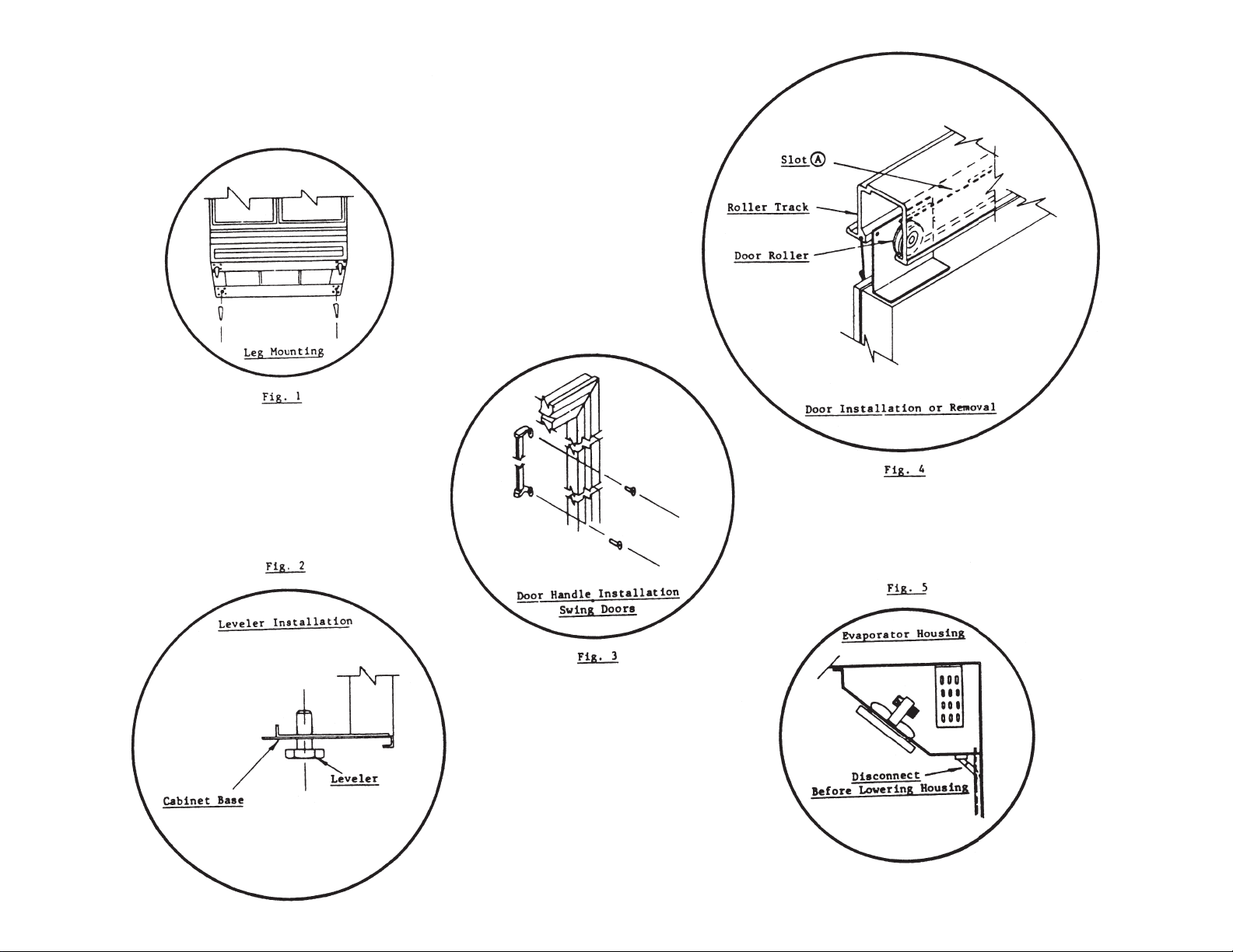
: (See Fig. 2)
: (optional) (See Fig. 1)
: (See Fig 3.)
:
e. Shelves
Shipped inside each cabinet are shelves packed in plastic and a bag of shelf supports. Shelf
spacing is adjustable to suit requirements. See Instruction Sheet ILA-0904 for installing.
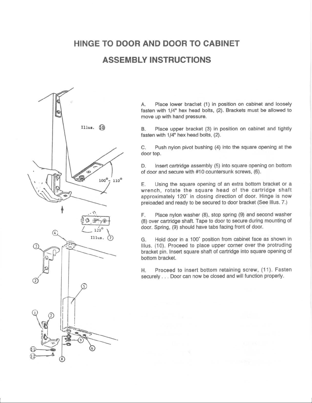
f. Door Removal and
(1) Slide Doors
Proper
a. Locate Door Rollers under slot A
Adjust spring by moving hook to next hole or by shortening.
If door gaskets do not seal properly follow step 1 and 2.
Step 1: Check to see if cabinet base is level.
Step 2: Adjust the Location
(2) Swing Doors
“Swing Back
instructions see enclosed instruction sheet ILA-0859.
g. Locating Cooler
Provide at least three inches of space
end and rear of cabinet.
* For FC model, factory setting of temperature control is at No. 4 position (normal) which will
:
- Each door has its own Closing Spring located at the top and is positioned for
Tension. However if adjustment is required remove doors as follows:
bottom of door out.
” of doors, and does not require field adjustment. For replacement parts and
:
maintain the flower at about 42°F.
Adjustment:
show in fig. 4, and lift door off track while tilting
፨
of door Rollers in the Roller Brackets.
- Spring tension in the bottom hinges is Factory Adjusted for adequate
between cabinet and any adjacent wall or fixture, at left
2. Operation
a. Electrical Supply and Connections:
Plug all standard models into 115 volts A.C. 60 cycle outlet. Low line voltage is often the cause
of service complaints. Check to see that the line voltage is 110 volts or more with the unit
running. Other motors or heavy appliances should not be used on the same circuit with the
cooler. When working on the inside of the cooler disconnect from electrical circuit for safety
reasons. CAUTION: If an extension cord is necessary, use only a three wire grounding type of
wire size 16 AWG or larger; do not exceed 20 ft. in length. The use of ungrounded cords or
overloaded circuits voids compressor warranty.
b. Initial Start-Up:
Turn Power on and check to verify that the condenser fan is running. On all Models, except
RI18, the defog fan and light switches are located on the blower housing front inside the
cabinet, the Defog Switch in “ON” position permits the Condenser Fan to run continuously for
maximum Door Defoging in high humidity locations.
c. Temperature Control:
Factory setting of temperature control is at No. 5 position (normal) which will maintain the
product at about 36°F.* For colder temperatures, turn knob clockwise one number at a time.
Excessive tampering with temperature control could lead to service difficulties. For operation
about 3000 ft. altitude, have thermostat adjusted by a qualified serviceman.
BEVERAGE-AIR®
ILA-0931
SHEET 2 OF 3
REV. B
d. Condensate Disposal:
The evaporator blower housing serves as a pan to collect and direct the condensate to the
evaporator pan located behind the front grille. Air flow over the pan hastens condensate
evaporation so that external drain plumbing is not required.
3. Maintenance
a. Cleaning Cabinet Exterior:
Cabinets should be cleaned with a solution of mild soap and water. Do not use caustic soap or
abrasive cleaners, since these might damage the cabinet finish. If stainless steel surface becomes
discolored, scrub by rubbing only in the direction of the finish grain. Do not use steel wool.
b. Cleaning Interior Surfaces:
The inside of the cabinet is coated with baked-on vinyl (except stainless steel cooler). To clean,
use mild soapy water and cloth or sponge.
c. Condenser:
For efficient operation, it is recommended that the condenser coil and fans be cleaned every
3 to 6 months. Remove front grille for access. Vacuum clean front surface of coil thoroughly or
direct forced air through condenser fins. Failure to clean condenser can cause compressor
malfunction and will void warranty.
d. Evaporator Fan:
Evaporator pan should be cleaned periodically to prevent odors and maintain evaporating
efficiency. The pan contains wicks to assist evaporation and should be replaced periodically.
e. Evaporator Housing:
If internal parts (e.g. fans, control) are to be serviced, lower housing as shown in (Fig 5). Make
certain to remove drain tube before lowering housing.
REV. B
SHEET 3 OF 3
ILA-0931

SHELF SUPPORT LOCATION ILLUSTRATION
ILB-1621
ALL MT'S
1/2" TAB
1/4" TAB
SHELF SUPPORT - REAR
WITH 1/2" TAB
( FULL SCALE )
SHELF SUPPORT - FRONT
WITH 1/4" TAB
( FULL SCALE )
REAR
1/2" TAB
FRONT
1/4" TAB
-- NOTES & INSTRUCTIONS --
1. PLACE SHELF SUPPORTS WITH 1/4" TABS INTO PILASTER AT DESIRED POSITION.
( NOTE THAT SUPPORTS WITH 1/4" TABS ARE LOCATED AT FRONT ONLY )
2. PLACE SHELF SUPPORTS WITH 1/2" TABS INTO PILASTER AT DESIRED POSITION.
( NOTE THAT SUPPORTS WITH 1/2" TABS ARE LOCATED AT BACK ONLY )
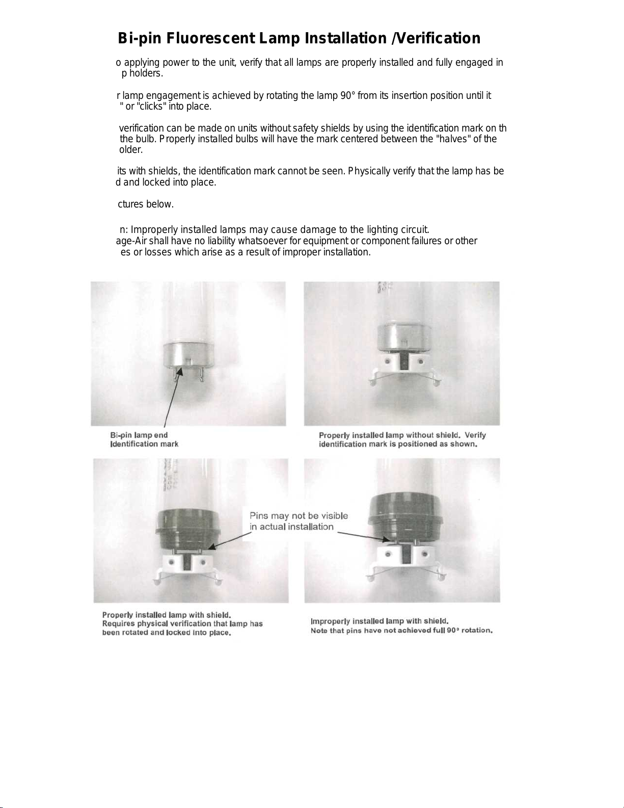
Bi-pin Fluorescent Lamp Installation /Verification
Prior to applying power to the unit, verify that all lamps are properly installed and fully engaged in
the lamp holders.
Proper lamp engagement is achieved by rotating the la mp 90° from its inserti on position until it
"snaps" or "clicks" into place.
Visual verification can be made on units without safety shields by using the identification mark on the
end of the bulb. Properly installed bulbs will have the m ark centered between the "hal ves" of the
lamp holder.
On units with shields, the identification mark cannot be seen. Physically verify that the lamp has been
rotated and locked into place.
See pictures below.
Caution: Improperly installed lamps may cause damage to the lighting circuit.
Beverage-Air shall have no liability whatsoever for equipment or component failures or other
damages or losses which arise as a result of improper install ation.
809-067A


METHODS FOR CLEANING STAINLESS STEEL
Routine Cleaning Soap, ammonia or Sponge with cloth, then Satisfactory for use on
detergent and water. rinse with clear water and all finishes.
wipe dry.
Stubborn spots and stains, Revere Ware cleaner, Apply with damp sponge Satisfactory for use on all
baked-on splatter, and Twinkle, or Cameo or cloth. Rub with damp finishes if rubbing is light.
other light discoloration's. stainless steel cleaner. cloth. Use in direction of polish
lines.
Goddard's Stainless Steel Apply with damp sponge or Use in direction of polish
Care, Revere Ware cloth. lines. May scratch or dull
Stainless Steel Cleaner, highly polished finishes.
Soft-Scrub.
Household cleansers, Rub with a damp cloth.
such as Old Dutch, Zud, May contain chlorine
Bon Ami, Ajax, Comet bleaches.Rinse
thoroughly after use.
Rub with a damp cloth.
Heat tint or heavy Revere Ware Stainless Apply with damp sponge
discoloration Steel Cleaner, Goddard's or cloth.
Stainless Steel Care.
CLEANING AGENT*
METHOD OF
APPLICATION**
EFFECT ON FINISH
Burnt-on foods and grease, Easy-Off Oven Cleaner Apply generous coating. Excellent removal.
fatty acids miikstone Allow to stand for 10 to 15 Satisfactory for use on all
(where swabbing or rubbing minutes. Rinse. Repeated finishes.
is not practical) application may be
necessary.
Hard water spots and scale Vinegar Swab or wipe with cloth. Satisfactory for use on all
Rinse with water and dry. finishes.
*Use of brand names is intended only to indicate a type of cleaner. This does not constitute an endorsement. Nor does
the omission of any brand name cleaner imply its inadequacy. Many products named are regional in distributior and can be
found in local supermarkets, department and hardware stores.
**lt is emphasized that all products should be us ed in strict a ccordan ce with instru ctions on p ackage.
1. Use the mildest cleaning procedure that will do the job efficiently and effectiv ely.
2. Always rub in the direction of polish l ines for maxi mum effectiv eness and to avoid m arring the surface.
3 . Use only a soft cloth, sponge, fibrous brushes, plastic or stainless steel pads for cleaning and sco uring.
4. Rinse thoroug hly with fresh water after every cleaning operation.
5 . Always wipe dry to avoid water marks.
6. Never use common steel wool pads, these will cause rust!
BEVERAGE-AIR
P.O. BOX 5932, Spartanburg, SC 29304-5932 Phone 800-845-9800 Fax 864-582-5083
MADE IN USA
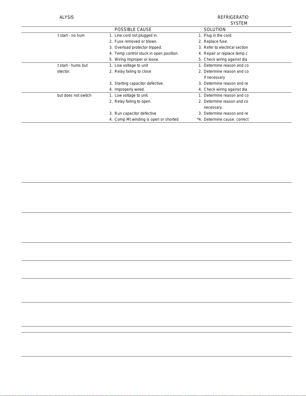
SERVICE AND ANALYSIS REFRIGERATION
CHART SYSTEM
MALFUNCTION POSSIBLE CAUSE SOLUTION
Compressor will not start - no hum 1. Line cord not plugged in. 1. Plug in the cord.
2. Fuse removed or blown. 2. Replace fuse.
3. Overload protector tripped. 3. Refer to electrical section.
4. Temp control stuck in open position. 4. Repair or replace temp control.
5. Wiring improper or loose. 5. Check wiring against diagram.
Compressor will not start - hums but 1. Low voltage to unit 1. Determine reason and correct
trips on overload protector. 2. Relay failing to close 2. Determine reason and correct, replace
if necessary
3. Starting capacitor defective. 3. Determine reason and replace
4. Improperly wired. 4. Check wiring against diagram
Compressor starts but does not switch 1. Low voltage to unit. 1. Determine reason and correct.
off of start winding. 2. Relay failing to open. 2. Determine reason and correct, replace if
necessary.
3. Run capacitor defective 3. Determine reason and replace.
4. Comp Mt winding is open or shorted *4. Determine cause. correct, and replace comp
Compressor starts and runs, but 1. Additional current passing through 1. Check wiring diagram. Check for added fan
short cycles on overload protector. overload protector. motors, pumps, etc. connected to wrong
side of protector.
2. Low voltage to unit. 2. Determine reason and correct.
3. Overload protector defective. 3. Check current, replace protector.
4. Run capacitor defective. 4. Determine reason and replace.
5. Excessive discharge pressure. *5. Check ventilation, restrictions in cooling
medium, restrictions in refrigeration system.
6. Compressor too hot - return gas hot. *6. Check refrigerant charge (fix leak if
necessary). Check air flow across condenser.
Unit runs OK, but short cycles. 1. Overload protector. 1. Check wiring diag for correct wiring
2. Cold control. 2. Differential set too close.
3. Overcharge. *3. Reduce refrigerant charge.
4. Air in system. *4. Recover and recharge.
5. Undercharge. *5. Fix leak and recharge with refrigerant.
Unit operates long or continuously. 1. Dirty condenser *1. Clean condenser
2. Shortage of refrigerant. 2. Fix leak, add charge, correct charge
3. Temp control contacts stuck or frozen 3. Replace Temp control
4. Evaporator coil iced. *4. Defrost
5. Restriction in refrigeration system. 5. Determine location and remove.
Start capacitor open, shorted or blown. 1. Relay contacts not opening properly. 1. Replace relay
2. Low voltage to unit. 2. Determine reason and correct.
3. Improper relay. 3. Replace.
Run capacitor open, shorted or blown. 1. Improper capacitor. 1. Determine correct size and replace.
2. Excessively high line voltage 2. Determine reason and correct.
(110% of rated max).
Relay defective or burned out. 1. Incorrect relay. 1. Check and replace.
2. Line voltage too high or too low. 2. Determine reason and replace.
3. Relay being influenced by loose 3. Remount rigidly.
vibrating mounting.
Space temperature too high. 1. Control setting too high. 1. Reset contr ol .
2. Overcharged with refrigerant. *2. Recover refrigerant and recharge with
proper charge specified on dataplate.
3. Inad equa te a ir circula tio n. 3. Improve air movement.
Cooler freezing beverage. 1. Temperature control 1. Reset control.
Unit noisy. 1. Loose parts or mountings. 1. Find and tighten.
2. Tub ing rattle. 2. Reform to be free of contact.
3. Bent fan blade causing vibration. 3. Replace blade.
4. Fan m o tor be arings worn. 4. Replace motor.
ALL SERVICING MUST COMPLY WITH STATE AND FEDERAL REGULATIONS
SALES OFFICE: P.O. BOX 5932, SPARTANBURG, SOUTH CA ROLINA 29 304
PLANTS: SPARTANBURG, SOUTH CAROLINA; HONEA PATH, SOUTH CAROLINA;
PHONE: 864-582-8111 TOLL F RE E: 1-800 - 84 5-9 80 0
BROOKVILLE, PENNSYLVANIA
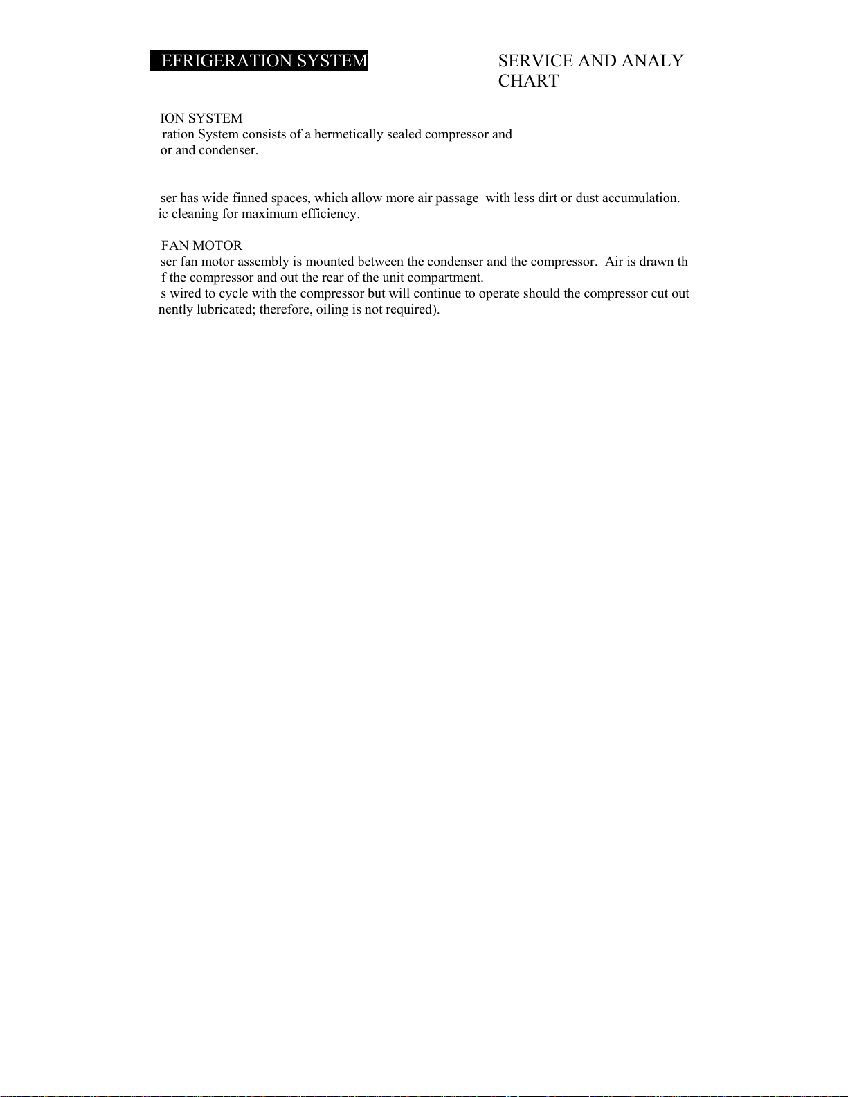
REFRIGERATION SYSTEM SERVICE AND ANALYSIS
CHART
!! REFRIGERATION SYSTEM
The Refrigeration System consists of a hermetically sealed compressor and
finned evaporator and condenser.
!! CONDENSER
The condenser has wide finned spaces, which allow more air passage with less dirt or dust accumulation. The condenser still
requires periodic cleaning for maximum efficiency.
!! CONDENSER FAN MOTOR
The condenser fan motor assembly is mounted between the condenser and the compressor. Air is drawn through the condenser,
over the body of the compressor and out the rear of the unit compartment.
The motor is wired to cycle with the compressor but will continue to operate should the compressor cut out on the overload. (The
motor is permanently lubricated; therefore, oiling is not required).
!! DRIER
The drier is installed in the system just before the capillary tube. Its purpose is to trap minute particles of foreign material and
absorb any moisture in the system.
!! LI!UID CONTROL AND HEAT EXCHANGE
Liquid refrigerant control to the evaporator of the system is accomplished by the use of a capillary tube. This capillary tube is
soldered to the suction line to form a heat exchanger which subcools the liquid refrigerant to maintain high efficiency within the system.
REFRIGERATION SERVICE
!! EVACUATION
Moisture in a refrigeration system is directly or indirectly the cause of more problems and complaints than all other factors
combined.
When large amounts of moisture are present, system freeze ups will occur. Even in minute amounts, moisture will combine with
refrigerants to form an acid. The corrosive action of this acid forms sludge, which will plug the lines and drier.
Since most field type vacuum pumps cannot pull a low enough vacuum to remove all moisture from the system, it is recommended
that the system be triple evacuated, breaking each time with dry refrigerant nitrogen. Use care to purge air from the charging hose when
breaking the vacuum.
!! CHARGING REFRIGERATION SYSTEM
Since capillary tube systems have small critical refrigerant charges, we recommend that a field charge either be weighed in or put in
from a portable charging cylinder. After maximum vacuum has been obtained as detailed above, attach charging cylinder to the system
line making sure to purge air from hose with refrigerant. With the unit running, allow refrigerant to run slowly into the system until the
desired charge is reached. When using Refrigerant Blends it is recommended to liquid charge into the high side of the system with the
initial charge and then any remaining charge can be put into the suction side; however, care must be taken to meter the remaining
amount into the low side so as not to cause excess liquid to go into the compressor.
OVERCHARGE
When the cabinet has pulled down to operating temperature,
an indication of an overcharge is that the suction line will be
cooler that normal with the compressor running. Running
time will be higher than normal. Suction line will sweat or
frost.
Reclaim excessive refrigerant from the system very carefully
in small amounts waiting several minutes for the system to
balance.
!"#"$%&'&%('$")**+$",'-.%-''$"!$+/"$%0-,'1"'$"234"$"#'5$+3$'-3',"$4+2+0/6'
1"4"$%/"7%+$'''' ' '''''''''''''''''''''''''''''''''''''''''''''''''''''+&%789:8' $"4' 1;,.-' <
UNDERCHARGE
An undercharge or shortage of refrigerant will result in any of
the following:
1.! Lower than normal head pressure.
2.! Lower than normal suction pressure.
3.! Excessive or continuous operation of compressor.
4.! Higher than normal cabinet temperature.
 Loading...