

Page 1

SERVICE &
INSTALLATION
MANUAL
Chest
Freezers
51-1371-04
02/03
CARRIER COMMERCIAL REFRIGERATION, INC.
Providing BEVERAGE-AIR • FRIGIDAIRE • KELVINATOR • UNIVERSAL NOLIN Products/Services
Page 2
If additional information is necessary, call the factory.
Our toll free number is 1-800-684-1199.Technical assis-
tance engineers are willing to assist you in any way possible. Office hours are from 7:30 a.m. to 5:30 p.m.,
Eastern Standard Time.
Important information is contained in this manual which should
be retained in a convenient location for future reference.
All data and information in this manual is subject to change without notice.
MODEL DESIGNATION INFORMATION
115V, 60HZ
PAR T N O. MODELS
52-1904-21 2SF-13
52-1904-22 4SF-13
52-1904-23 4DF-13
52-1904-24 6DF-13
52-1904-25 8DF-13
52-1904-33 8FR-13
52-1904-26 10DF-13
52-1904-27 14DF-13
52-2034-01 DI4-2
EXPORT 220V, 50HZ
PAR T N O. MODELS
52-1904-34 E2SF-13
52-1904-35 E4SF-13
52-1904-36 E4DF-13
52-1904-37 E6DF-13
52-1904-38 E8DF-13
52-1904-39 E8FR-13
Page 3
SECTION I
General
Maintenance
& Repair
Ice Cream Cabinets
Except for routine cleaning, these chest freezers
require little maintenance. In the unusual event
that repair should be necessary , this manual presents information that is helpful in maintaining,
diagnosing, and repairing these cabinets.
Page 4

Table of Contents
GENERAL MAINTENANCE & REPAIR
Installation/Operation .......................................................... 3
Grounding Instructions ...................................................... 4
Cleaning Instructions .......................................................... 5
Defrosting Instructions ...................................................... 6
2SF / 4DF / 4SF / DI4 Specs. & Drawings .......................... 7
6DF / 8DF / 10DF / 14DF Specs. & Drawings .................... 8
8FR Specs. & Drawings ...................................................... 9
General Operations Information ........................................ 10
Cabinet Construction ........................................................ 10
Cooling Tank Assembly .................................................... 10
Chamber Guards .............................................................. 10
Replacing Chamber Guards .............................................. 11
Lids .................................................................................. 11
Replacing Stainless Steel Top Cap .................................... 11
Refrigerating Systems ...................................................... 11
Condenser ........................................................................ 11
Filter Drier ........................................................................ 12
Capillary Tube .................................................................. 12
Heat Exchanger ................................................................ 12
Replacing Heat Exchanger ................................................ 12
Refrigerant Cycle - Condenser & Evaporator .................. 13
Electrical Service .............................................................. 14
Thermostat ...................................................................... 14
Condensate Heater ............................................................ 15
Motor & Relay .................................................................. 16
Checking For Electrical Trouble ........................................ 17
Refrigeration Service: Compressor Installation ................ 17
Refrigerant Service .......................................................... 17
Cleaning System After Burnout ........................................ 19
Wiring Diagram: Chest Models ........................................ 20
ELECTRICAL & REFRIGERATION
SPECIFICATIONS
2SF-13 & 4SF-13 (R-404A) .............................................. 21
4DF-13 & 6DF-13 (R-404A) .............................................. 22
8DF-13 / 8FR-13 & 10DF-13 (R-404A) ............................ 23
14DF-13 & DI4-1 (R-404A) .............................................. 24
PAR TS LISTS
Cabinet Parts Illustration (R-404A) .................................. 26
Cabinet Parts Listing (R-404A) ........................................ 27
Cabinet Parts Listing (R-404A) Export................................28
Condensing Unit Comp. Listing (R404A) Export ................29
Condensing Unit Compartment Illustration (R404A) ..........30
Condensing Unit Compartment Listing (R404A) ................31
Condensing Unit Compartment Illustration & Listing
Model DI4-1........................................................................32
8FR Parts Listing (R-404) & Accessory Mounting .......... 33
Cleaning Chocolate & Syrup Pumps ................................ 33
Accessory Mounting Limitations ...................................... 34
Caster Assembly Installation ............................................ 35
2TABLE OF CONTENTS
Page 5

Installation & Operation Instructions
These instructions include information which is intended
to assure the operator of correct installation, operation,
and service. Before attempting installation, adjustment
or maintenance, be certain of the following:
1.That you have read and fully understand the instructions.
2.That you have all the tools required and are trained to
use them.
3.That you have met all installation and usage restrictions and are familiar with the functions and operation
of the unit.
4.That you follow all instructions exactly as given.
All fittings, measurements, procedures and recommendations are significant. Substitutions and approximation
must be avoided. Improper handling, maintenance,
installation and adjustment or service attempted by anyone other than a qualified technician, may void the
future warranty claims and cause damage to the unit
and/or result in injury to the operator and/or bystanders.
Record for Service
Model No. __________________________________
Serial No. ____________________________________
Installation Date ______________________________
Invoice Date__________________________________
Start-up Date ________________________________
Telephone for Service __________________________
INSTALLATION INSTRUCTIONS
Thermostat will maintain approximately zero degrees on
the original factory setting. Turn the adjusting screw
clockwise for colder and counterclockwise for warmer.
IMPORTANT: Turning control counterclockwise to the
stop shuts cabinet "OFF".
For storage of package ice cream, turn thermostat to
coldest position. Limit top layer of package to a height
consistent with cabinet usage and turn over of product.
LOCATION
Select a location for the cabinet which will be most convenient for the customer and which will allow adequate
air circulation.Restricted air flow will result in higher condensing pressures and operating costs.
Provide at least a 1-inch space around the exterior of
the cabinet. The outside shell is the condenser and
depends on the natural convection of room air for dissipation of its heat. Stainless or formica facing sheets
applied to the cabinet exterior should be in tight contact
with the cabinet's outer walls to improve the heat flow.
When a cabinet is built into a counter or back-bar and
space is allowed between the counter and the cabinet
walls, provide holes or louvers along the top edge f or hot
air to escape.Holes should be screened to keep insects
and rodents out.
IMPORTANT: Before building any piece of equipment
in, run it to be sure the operation is satisfactory.
BE SAFE. SEE ILLUSTRATION ABOVE.
When a cabinet is installed in a moving vehicle, use the
original crate mounting angles or equivalent to securely
bolt the cabinet to the vehicle floor so it won't move
going around corners or during sudden starts and stops.
INSTALLATION & OPERATION 3
Important information is contained in
these instructions which should be
retained in a convenient location for
future reference.
Page 6

Grounding Instructions
This appliance is equipped with a three-prong (grounding) plug for your protection against shock hazards.The
appliance should be plugged directly into a properly
grounded three-prong receptacle.
Where a two-prong wall receptacle is encountered, it
must be replaced with a properly grounded three-prong
receptacle in accordance with the National Electrical
Code and local codes and ordinances. The work must
be done by a licensed electrician.
IMPORTANT
Do not, under any circumstances cut or remove the
round grounding prong from the appliance plug.
WARNING
Consult a licensed electrician if you have any
doubt about the grounding of your wall
receptacle. Only a licensed electrician can
determine the polarization of your wall
receptacle. Only a properly installed threeprong wall receptacle assures the proper
polarization with the appliance plug.
4 GROUNDING INSTRUCTIONS
20 Amp
15 Amp
15 Amp
20 Amp
Page 7

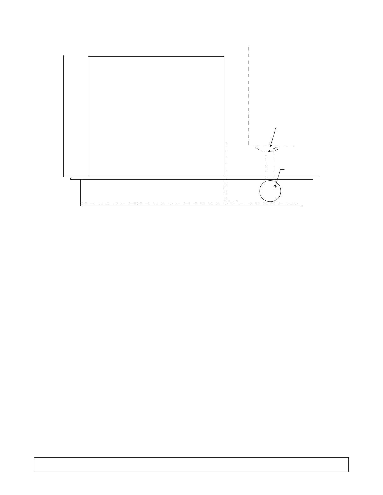
FIG. 2
Cleaning Instructions
DIRECTIONS FOR PROPER CARE &
CLEANING
1.Wipe up spilled foods promptly.
2. Use lukewarm detergent solution for cleaning the
cabinet interior, exterior, and lids.Follow with a clean,
damp cloth and then wipe dry.
3. Protect the exterior enamel finish and plastic lid frame
with automotive type cleaner and wax.
4. Protect all stainless steel surfaces with a commercial
silicone emulsion type cleaner.This cleaner is excellent for all stainless steel surfaces. It leaves a protecting film that prevents fingermarking and the adherence of food particles.
5. CAUTION:
a. Never use naptha or solvent type cleaner on plas-
tic parts or lid frames.
b. Never u se harsh abrasive polishes on plastic parts
or plastic lid frames.
c. Do not blow steam or dash excessively hot water
against plastic materials when cleaning the tank or
defrosting, as damage to plastic parts may occur.
6.When the cabinet is taken out of service for more than
a short period:
a. Remove lids. (DO NOT replace them on the cabi-
net until the cabinet is again refrigerated.)
b. Defrost cabinet and remove any spilled ice cream
from the chamber guards.
c.Wash and dry chamber guards and cabinet interi-
or.(See Item 2 above.)
INSTRUCTIONS FOR SEALING
CABINET TO FLOOR
The National Sanitation Foundation recommends these
cabinets be sealed to the floor to prevent w ater, dirt and
vermin, etc. from getting under the cabinet. The instructions below meet their requirements.
1. Position and level the cabinet.
2. Draw outline of the base on the floor.
3. Raise and block the front side of the cabinet as illustrated in FIG. 1.
4. Apply a bead of mastic (See approved list below) to
the floor one half inch inside the outline drawn. (See
FIG. 2.) Bead must be heavy enough to compress at
all points when the cabinet is set down.
5. Raise and block the rear of the cabinet as illustrated
in FIG. 1.
6. Apply mastic on the floor as outlined in step 4 on the
other three sides.
7. Examine to see that cabinet is sealed to floor around
entire perimeter.
NOTE. Asphalt floors are very susceptible to chemical
attack. A layer of tape on the floor prior to applying the
mastic will protect the floor.
APPROVED MASTICS
3M #EC800 ............................................................Caulk
3M #EC2185 ..........................................................Caulk
3M #EC1055 ..........................................................Bead
3M #EC1202 ..........................................................Bead
Armstrong Cork ........................................Rubber Caulk
Products Research Co.#5000..................Rubber Caulk
G.E. Silicone Sealer
CLEANING INSTRUCTIONS 5
FIG. 1
Page 8
Defrosting Instructions
A drain fitting is located in the bottom of the storage
tank.To drain the defrost water:
1. Remove and store products in another freezer.
2. Loosen and remove any items such as ice cream,
nuts, berries, paper labels, etc., which could plug the
bottom drain.
3. Remove the cap from the drain hose fitting.
4. Connect a hose to the fitting and run it to a floor drain,
a shallow (2" high maximum) pan, or to a “Filordrain”
at the sink.
5. Disconnect the cabinet by pulling the plug or turning
the thermostat off to melt down the frost.You can hasten the defrost by using the “Filordrain” or a hose to
spray warm water on the cabinet walls. (Detailed
instructions for using the “Filordrain” for spraying the
frost and removing the accumulated water are available from your dealer.)
6. Recap hose fitting after defrosting is complete.
6 GROUNDING INSTRUCTIONS
COMPRESSOR COMPARTMENT
DRAIN IN LINER
DRAIN CAP
Page 9
Specifications - Specifications Subject to Change without Notice.
DI4 2SF 4DF 4SF
Compressor Mount Front Front Front Front
Temperature Range 0° to -20°F (-18° to -29°C) 0° to -25° 0° to -25° 0° to -20°
Number of Lids 2 2 2 4
Lid Construction Stainless Steel, High Density, High Density, Foamed-in-Place High Density, Foamed-in-Place High Density, Foamed-in-Place
Foamed-In-Place Insulation w/ Vinyl Gaskets Insulation w/ Vinyl Gaskets Insulation w/ Vinyl Gaskets
Insulation w/ Vinyl Gaskets
Hinge Type Continuous Composition Continuous Composition Continuous Composition Continuous Composition
Insulation Polyurethane Foam Polyurethane Foam Polyurethane Foam Polyurethane Foam
Wall Thickness 2-1/4" 2-5/16" 2-5/16" 2-5/16"
Capacity 4.9 cu. ft. 5.4 cu. ft. 9.1 cu. ft. 11.3 cu. ft.
Capacity
3 gal. (9-
1
⁄2" I.D.) cans 6 4 9 10
2-
1
⁄2 gal. (9" I.D.) cans 6 5 10 13
2-
1
⁄2 gal.(9-1⁄4" I.D.) cans 6 5 12 15
1
⁄2 gal. packages — 63 116 136
Shipping Weight 210 lbs. 212 lbs. 247 lbs. 294 lbs.
Compressor Size 1/5 HP 1/5 HP 1/5 HP 1/5 HP
Condenser Type Forced Convection No-clog, Wrap-around No-clog, Wrap-around No-clog, Wrap-around
Radiant Shell Radiant Shell Radiant Shell
Evaporator Type Cold Wall Cold Wall Cold Wall Cold Wall
Refrigerant Type R404A R-404A R-404A R-404A
Refrigerant Control Capillary Capillary Capillary Capillary
Defrost System Manual Manual Manual Manual
Amp Draw 2.0 2.0 2.0 2.0
Electrical Specs. (V/Hz/Ph) 115/60/1 115/60/1 115/60/1 115/60/1
NSF-7 (Ice Cream Storage) Yes Yes Yes Yes
UL & CUL Listed Yes Yes Yes Yes
Interior Finish Baked Enamel on Galvanized Steel Baked Enamel Baked Enamel Baked Enamel
Exterior Finish Unpainted Galvannealed Steel Baked Enamel Baked Enamel Baked Enamel
w/ Stainless Steel Cap w/ Stainless Steel Cap w/ Stainless Steel Cap w/ Stainless Steel Cap
Electrical Information Conduit Connected, Max. Fuse 15 Amp Service Cord 15 Amp Service Cord 15 Amp Service Cord
Size: 15 Amp, Circuit Ampacity: 15A NEMA 5-15P Plug NEMA 5-15P Plug NEMA 5-15P Plug
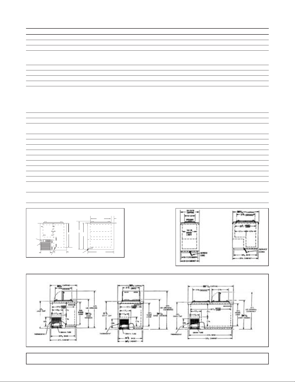
DI4 / 2SF / 4DF / 4SF SPECIFICATIONS 7
SF
Side View
DF
Side View
DI4 Front View
DI4 Side View
Model 2SF
Model 4DF Model 4SF
Thermostat
on Side
Handy
Box
10 7/8"
TYP.
1/2"
11 1/8"
13"
13"
Drain
12 1/8"
10 1/8"
25 1/2"
29 3/8"
Connector for
Drain Hose
27 3/4"
22 1/4"
SQ.
21 5/8"
Reach In Opening
2 1/4"
TYP.
Page 10

8 6DF / 8DF / 10DF / 14DF SPECIFICATIONS
Specifications - Specifications Subject to Change without Notice.
6DF 8DF 10DF 14DF
Compressor Mount Front Front Front Front
Temperature Range 0° to -20°F 0° to -20° 0° to -20° 0° to -25°
Number of Lids 4 4 6 8
Lid Construction High Density, Foamed-In-Place High Density, Foamed-in-Place High Density, Foamed-in-Place High Density, Foamed-in-Place
Insulation w/ Vinyl Gaskets Insulation w/ Vinyl Gaskets Insulation w/ Vinyl Gaskets Insulation w/ Vinyl Gaskets
Hinge Type Continuous Composition Continuous Composition Continuous Composition Continuous Composition
Insulation Polyurethane Foam Polyurethane Foam Polyurethane Foam Polyurethane Foam
Wall Thickness 2-5/16" 2-5/16" 2-5/16" 2-5/16"
Capacity 14.1 cu. ft. 18.6 cu. ft. 23.6 cu. ft. 31.5 cu. ft.
Capacity
3 gal. (9-
1
⁄2" I.D.) cans 16 21 29 40
2-
1
⁄2 gal. (9" I.D.) cans 19 25 33 47
2-
1
⁄2 gal.(9-1⁄4" I.D.) cans 21 30 40 56
1
⁄2 gal. packages 173 234 298 103
Shipping Weight 304 lbs. 353 lbs. 396 lbs. 598 lbs.
Compressor Size 1/3 HP 1/3 HP 1/3 HP (2) 1/3 HP
Condenser Type No-clog, Wrap-around No-clog, Wrap-around No-clog, Wrap-around No-clog, Wrap-around
Radiant Shell Radiant Shell Radiant Shell Radiant Shell
Evaporator Type Cold Wall Cold Wall Cold Wall Cold Wall
Refrigerant Type R-404A R-404A R-404A R-404A
Refrigerant Control Capillary Capillary Capillary Capillary
Defrost System Manual Manual Manual Manual
Amp Draw 3.0 3.0 5.5 6.0
Electrical Specs. (V/Hz/Ph) 115/60/1 115/60/1 115/60/1 115/60/1
NSF-7 (Ice Cream Storage) Yes Yes Yes Yes
UL & CUL Listed Yes Yes Yes Yes
Interior Finish Baked Enamel on Galvanized Steel Baked Enamel Baked Enamel Baked Enamel
Exterior Finish Unpainted Galvannealed Steel Baked Enamel Baked Enamel Baked Enamel
w/ Stainless Steel Cap w/ Stainless Steel Cap w/ Stainless Steel Cap w/ Stainless Steel Cap
Electrical Information 15 Amp Service Cord 15 Amp Service Cord 15 Amp Service Cord 15 Amp Service Cord
NEMA 5-15P Plug NEMA 5-15P Plug NEMA 5-15P Plug NEMA 5-15P Plug
Model 6DF
Model 8DF
Model 10DF
Model 14DF
Page 11
8FR SPECIFICATIONS 9
Specifications - Specifications Subject to Change without Notice.
8FR
Compressor Mount Front
Temperature Range 0° to -20°F
Number of Lids 2
Lid Construction High Density, Foamed-In-Place
Insulation w/ Vinyl Gaskets
Hinge Type Continuous Composition
Insulation Polyurethane Foam
Wall Thickness 2-5/16"
Capacity 14.1 cu. ft.
Capacity
3 gal. (9-
1
⁄2" I.D.) cans 21 - 12 top / 9 bottom
2-
1
⁄2 gal. (9" I.D.) cans 25
2-
1
⁄2 gal.(9-1⁄4" I.D.) cans 30
1
⁄2 gal. packages 234
Shipping Weight (Approx.) 353 lbs.
Compressor Size 1/3 HP
Condenser Type No-clog, Wrap-around
Radiant Shell
Evaporator Type Cold Wall Shell
Refrigerant Type R404A
Refrigerant Control Capillary
Defrost System Manual
Amp Draw 3.0
Electrical Specs. (V/Hz/Ph) 115/60/1
NSF-7 (Ice Cream Storage) Yes
UL & CUL Listed Yes
Interior Finish Baked Enamel on Galvanized Steel
Exterior Finish Baked Enamel
w/ Stainless Steel Cap
Electrical Information 15Amp Service Cord
NEMA 5-15P Plug
8FR
Page 12

Operation - General
All the chest freezer models are of the same basic
design consisting of a hot wall condenser cap tube fed
tank wrap evaporator. Ice formation on the walls over a
period of time is normal.This frost should be scraped off
periodically in order to maintain peak performance.
These cabinets are thermostatically controlled for various temperature requirements. The thermostat is
located post adjacent to the unit compartment and can
be accessed for adjustment by the user with a screwdriver or a dime. Thermostat position #1 being the
warmest and position #7 being the coldest.
These cabinets are manual defrost and a drain is provided for periodic cleaning. A garden hose can be
attached to the drain plug for draining any water that
may accumulate.This drain attachment is located in the
front base rail of the cabinet.
NOTE: The power supply cord must be disconnected
when cleaning or servicing these cabinets.
On initial cabinet pulldown, the hot wall condenser may
become warm to the touch until the normal operating
temperatures are achieved.
Refer top model serial data tag for cabinet amperage,
refrigerant charges and type.
CABINET CONSTRUCTION
The low side tank is lowered into the outer shell and
anchored to the sub top by a plastic extrusion and foam.
The space between the outer wrapper and the inner
tank is then filled with urethane foam insulation (2-1⁄4"
thick) forming a three-ply wall of single unit construction.
The low side tank then is not removab le and no repair of
the low side can be made.
The stainless steel top capping is of drawn one piece
construction. It is put in place after the inner tank is
assembled to the wrapper and is secured to the sides of
the cabinet with 1⁄8" pop rivets.
COOLING TANK ASSEMBLY
The low side assemblies are designed so that the sides
and the ends of the tank are refrigerated.
The evaporator coil assembly on the tank is different to
that on previous models. It is now a serpentine coil
arrangement.The new evaporator starts at the top of the
inner tank and spirals downward to the condensing unit.
The thermostat bulb well is located near the front of the
machine compartment in all models.
CHAMBER GUARDS
The one-piece vinyl chamber guard extends from the
top of the lid opening down into the inner tank.
Galvanized steel chamber guard retainers mounted in
the top of the tank frame hold the vinyl chamber guard
against the top stainless steel capping.A special sealing
compound laid on the inside angle of the retainers seals
the vinyl to the stainless steel capping. One-piece
retainer brackets along the low er edge of the tank frame
retain the lower edge of the vinyl chamber guard.
To remove the vinyl chamber guard, merely unhook
from lower edge of the brackets and the top edge of the
chamber guard retainers. (See below)
10 GENERAL OPERATIONS
Page 13

REPLACING THE CHAMBER GUARD
To install the New Vinyl Guards, Proceed as Follows:
1. Clear off the old mastic from around the top chamber
guard retainer.
2. Mastic is to be used between the stainless s te el t op
and the top chamber guard retainer. Hold the
tapered edge of the spout at an angle, then press
on tube and force mastic out.Pull along the retainer at an even pace.
3. Hook the four corners of the chamber guard in place
and work the top edge along the top retainers hooking
the top edge in place. (B). Then stretch the chamber
guard downward, and hook in place over the bottom
retainer (C). If there is any excess mastic from around
top, Hexane, light naptha, will remove the mastic.
LIDS
The cabinet lids of the Flip-Flop design are made in two
widths: single width and double width.The double width
lids are for the double row cabinets and co v er the square
area so the lids may be placed to lift from side to side of
from end to end as desired. Stainless steel lid assemblies are made in two widths.
To replace the hinges, proceed as follows:
1. Remove the lid from the cabinet.
2. Remove the screws securing the hinge plate to the lid.
3. Remove the defective hinge.
4. Align the new gasket and hinge plate in insert screws.
REPLACING STAINLESS STEEL TOP CAP
Should it become necessary to remove or replace the
top capping, the rivets can easily be removed by drilling
out with a small electric drill using a No.30 drill to insure
not increasing the size of the hole in either the cap or the
wrapper. In reassembling, install 1/8" aluminum pop
rivets, Number 576860, in the holes throughout the stainless steel cap and the cabinet wrapper.
REFRIGERATING SYSTEMS
All compressors have fusite mounted terminals and a
plug-on starting relay. The overload protector plugs on
the common fusite terminal.
The compressor and motor are built as one unit and
spring mounted inside a steel shell.Welded construction
makes the unit hermetically sealed. The compressor
embodies a reciprocating type pump, directly
connected to the motor.
An oil pump supplies oil to every moving part and literally floods every bearing surface with oil to minimize
friction and insure quiet operation. The compressor
dome is four-point base mounted.
CONDENSER
The condenser tubing is held to the inside of the cabinet
wrapper or shell along the front, the back, by saddle
clamps which are spot welded to the outer shell.
Efficient heat transfer is obtained from the tube to the
entire shell which is the condenser surface. By the natural convection of the room air due to the absorption of
the heat from the wrapper, an efficient cooling action is
obtained and sufficient heat is removed from the hot
compressor refrigerant vapor to result in the liquidation
of the refrigerant. During the initial pull down of a hot
GENERAL OPERATIONS 11
Page 14

12 GENERAL OPERATIONS
cabinet in a warm room the wrapper will be warm to
the touch. This is a nor mal condition with this type of
condenser.
The wrapper type condenser is free of many of the faults
common to the conventional type system. Because of
the design there are no fans to fail; no fins to clog with
grease, lint or dust causing high condensing temperatures. The condensing temperatures compare very
favorably with other types and the system has the added
advantage that condenser efficiency is constant
throughout the life of the cabinet.
FILTER DRIER
A filter drier’s purpose is to filter and trap minute particles of foreign materials and absorb any moisture which
may be in the system.
The drier is located in the liquid line ahead of the capillary tube. A fine mesh screen filters out foreign particles
and the desiccant absorbs the moisture.
REPLACING THE FILTER DRIER
1. Disconnect the cabinet from its power source.
2. Install a tap line service valve to both the high and low
side process tubes.
3. Attach a compound gauge manifold to system.
4. Hook up refrigerant reclaimer to system and remove
all refrigerant from cabinet.
5. Remove drier from system.
6. Replace with same part number. Changing drier
size will effect the system charge.
7. Evacuate system to 500 microns.
8. Refer to cabinet data plate for proper charge and type
of refrigerant used.
CAPILLARY TUBE
A capillary tube is used to regulate the flow of liquid
refrigerant into the low side of the system.Its resistance
or pressure drop due to the length of tube and smaller
diameter, meters the flow of the refrigerant.
HEAT EXCHANGER
The liquid and suction lines are soldered together to
form an efficient heat exchanger .The warm liquid refrigerant is sub-cooled by the cold suction vapor prior to
entering the low side.The heat exchanger is located in
the area above the compressor
REPLACING THE HEAT EXCHANGER
1. Disconnect the cabinet from the power source.
2. Install service tops to process tube on high and low
sides of system.
3. Attach a manifold gauge set.
4. Reclaim all refrigerant in cabinet.
5. Remove cork impregnated tape from refrigerant
lines at bottom of cabinet.
6. Disconnect heat exchanger suction line from low
side outlet line.
7. Disconnect the capillary line from the low side inlet
line.
8. Place replacement heat exchanger in position and
connect the lines.
9. Replace the filter drier.
10. Evacuate system below 500 microns.
11. Refer to cabinet data plate for charge and type of
refrigerant.After charging, pinch off service taps and
braze tube closed.
Page 15

REFRIGERANT CYCLE Condenser & Evaporator
Liquid refrigerant is evaporated in the low side coil by
heat absorbed from the tank walls. The refrigerant
passes as a vapor from the accumulator through the
suction line to the compressor. It enters the interior of
the shell which is at suction pressure. From the top of
the shell, vapor passes down through a tube into the
compressor cylinder. The pressure (and temperature)
of the vapor is raised in the cylinder by the compression
and the vapor is then forced through the discharge
valve and into the discharge line leading to the
condenser on where the vapor is cooled and some
condensation to a liquid takes place.
GENERAL OPERATIONS 13
Page 16

ELECTRICAL SERVICE
THERMOSTAT
The thermostat is mounted in the machine compartment
at top or left side of front opening and the thermal element is extended into the thermostat well. See Figure
10.The well is a cylindrical tube fastened to the exterior
of the inside tank, It is located near left front corner of
the machine compartment (left rear on single row).
NOTE: Caution must be exercised when replacing a
thermostat from thermal element tube so it does not
touch any of the refrigeration lines in the machinery
compartment. Because it senses the coldest temperature before attempting to change the range or the cutout point, make sure the thermostat thermal
element is properly inserted into the well to the red
mark.The correct distance from the end of the element
to the red mark on the element should be 22". Always
remember a poor contact will naturally affect the operating range and cabinet temperature.See table below.
The range and the cut-out point of differential can be
adjusted to settings other than those given in the table.
If a higher or lower range than is obtainable by the slotted shaft is desired, change the adjustment screw
located between the two space connector behind the
control.Turn the adjustment screw clockwise to raise the
temperature, and counterclockwise to lower the range.
THERMOSTAT - Adjusting Screw
The differential adjusting screw is covered with a liquid
sealer which must be removed before any adjustment
can be made. Turn the differential screw clockwise to
lower the cut-in temperature and narrow the differential.
Turn the screw counterclockwise to raise the cut-in
temperature and widen the differential.Adjust the screw
only if has been proven that the thermostat differential is
too narrow — less than 9.5°F, or too wide, 14.5°F.
THERMOSTAT- Temp Adjustment
Thermostat dial is labeled #1 thru #7. #1 being warmest
and #7 being coldest. To lower cabinet temperature,
insert a dime or screwdriver in the slot provided and turn
clockwise.
GENERAL OPERATIONS 14
THERMOSTAT SPECIFICATIONS
Differential at Mid-Position 9-1/2 to 14-1/2°F
TEMPERATURE SETTINGS AT CONTROL BULB - °F.
WARM POSITION MID-POSITION COLD POSITION
THERMOSTAT #1 CUT-IN OUT CUT-IN OUT #7 CUT-OUT
762938 or +20° 0 -1° -16° -30°
23-5117
2
1
3
4
7
5
6
Page 17

Condensate Heater
TO REPLACE HEATER WIRE
1. Unhook the bottom edge of the chamber guard and
remove.
2. Pull out screw nails and lift out chamber guard
retainer.
3. Unplug and pull out original heater, carefully checking
for any damaged areas. Carefully check recess for
heater where damaged heater wire was installed.
4. Plug in one end of the replacement heater (see FIGURE 14),and carefully insert heater in recess aroud
top opening.Tuck any excess lenght in space jprovided after plugging in the opposite end of the heater
wire. Reconnect the heater wiring. Replace in slots
provided and reseal cavity with clear silicone.
5. Check that heater operates before replacing retainer
and chamber guard.
GENERAL MAINTENANCE & REPAIR 15
Page 18

MOTOR & RELAY
Split phase motors are used in all compressors.Models
6-DF, 8-DF, and 10-DF have 2-pole, 3450 RPM motors.
The use of low starting torque motors is made possible
by unloading the compressor prior to the start, thus
reducing the required starting torque.
The starting relays on the “A” line compressors is the
push on type that mounts on the Start (S) and Run (R)
terminals of the compressor, as shown in Figure 15
below.The starting relay is a magnetic switch with starting contacts. Its magnetic coil is in series with the run
winding of the motor. The relay coil carries the main
winding current. The relay armature holds the starting
winding contacts in open position except during the
starting period. At the moment of starting, when the
thermostat closes the electrical circuit, a surge of electrical current passes through the main motor winding
and through the relay coil.
This energizes the relay coil and pulls up the rela y armature, allowing the starting winding contacts to close.The
current through the start windings introduces a second
out of phase, magnetic field in the starter and starts the
value motor. As the motor speed increases, the main
winding current is reduced. At a predeter mined condition, the main winding current, which is also the current
through the relay coil, drops to a value below that necessary to hold in the relay armature.The armature drops
and opens the starting winding contacts and takes the
starting winding out of the circuit.
Refrigerant 404A compressors utilize a Positive
Temperature Coefficient resistor (P.T.C.) The PTC resistor is connected in parallel with the run capacitor and in
series with the start winding. The PTC has a low resistance when it is cold. When the motor starts the low
resistance causes a large current to flow through the
resistor. Current drawn by the resistor is out of phase
with the current drawn by the motor windings. As the
resistor draws current it begins to heat and resistance
builds to a point where it cannot flow to the start windings, thus switching current to the run windings.
In series with the motor windings is a separate bi-metal
overload protector held in place on the compressor by a
spring clip.The short wire lead on the overload protector
connects to the common (C) terminal on the compressor.
Should the current in the motor windings increase to a
dangerous point, the heat developed by passage of the
current through the bi-metal disc will cause it to deflect
and open the contacts.This act breaks the circuit to the
motor windings and stops the motor before any damage
can occur.
The overload protector provides added protection f or the
compressor motor because in addition to protecting
against excessive current it also protects against excessive temperature rises.
After an overload or a temperature rise has caused the
overload protector to break the circuit, the bimetal disc
cools and returns the contact to the closed position.The
time required for the ov erload s witch to reset varies with
room temperature and compressor dome temperatures.
The overload protector is specifically designed with the
proper electrical characteristics for the compressor
motor and this ice cream cabinet application. Any
replacement must be made with the exact replacement
“NEVER SUBSTITUTE AN OVERLOAD
PROTECTOR WITH ANOTHER OF AN
UNAUTHORIZED PART NUMBER.”
The wrong protector can result in a burnt out motor. If
either the overload protector or the relay is found inoperative, both the rela y and protector should be replaced.
When the thermostat cuts off after normal cycle or when
the service cord is pulled from the wall during a running
cycle, about eight (8) minutes time is required for
unloading (longer if it occurs during pull down), which is
the reduction of the pressure differential between the
high side and the low side of the system. During this
unloading period, the overload will trip if the service cord
is plugged into the electrical outlet.
If the compressor does not start, look for other trouble
(low line voltage—less than 100 volts at the compressor
terminals during the star ting interval, inoperative relay,
inoperative compressor).
Since the relay is current operated and is designed f or a
specific compressor and motor current value, the current size relay represented by the part number is an
absolute must.
“NEVER SUBSTITUTE AN OVERLOAD
PROTECTOR WITH ANOTHER OF
AN UNAUTHORIZED PART NUMBER.”
These relays cannot be adjusted or properly repaired in
the field. If the compressor repeatedly star ts and runs
for a few seconds, and then cycles on the overload protector, the starting relay contacts may be stuck closed
and the excessive current is tripping the overload.
16 GENERAL OPERATIONS
Page 19

CHECKING FOR ELECTRICAL TROUBLE
When checking for electrical trouble, always be sure
there is a “live”electrical circuit to the cabinet and that the
thermostat dial is not in the “OFF” position. When the
sealed unit will not start and the cabinet temperature is
warm, the trouble may be in the relay, in the ther mostat,
in the wiring, or it may be in the compressor motor itself.
If the compressor will not run, make a test across the
power lead terminals (one at the relay, the other at the
overload protector). See Figure 15, page 18. The test
should show a live circuit if the thermostat knob is in the
normal operating position and not in the “OFF” position.
If this check does not show positive, the thermostat and
wiring should be checked for an open circuit.
If the compressor motor does not start, check the line
voltage, to see that there is not more than 10% variation
from the normal 115 volts. If the voltage is correct, relay
and overload check out, and the compressor will not start
and run, change the compressor.Even though the cause
of the electrical trouble is determined, check the complete electrical circuit. Look for broken wire, wires with
frayed ends, and loose terminals.
REFRIGERATION SERVICE
OPERATING CHARACTERISTIC
On the initial startup of a warm cabinet, the suction pressure drops rapidly to about 0 to 5 pounds.This will vary
some with the temperature of the cabinet and the ambient temperatures.After 15 to 20 minutes of operation, the
suction pressure begins to rise again and will rise to
about 20 to 30 pounds.
The head pressure also rises and they both “peak” or
stop rising about 30 to 60 minutes of operation.
Abnormally warm cabinets and high ambient temperatures will affect both the pressure and the time interval
involved by raising the pressures and lengthening the
intervals.
After this “peak” has been reached, the discharge and
suction pressures begin to drop slowly.
After some 30 minutes of operation, the system starts to
lower the air temperature inside the cabinet. The discharge pressure will gradually lower as the cabinet temperature drops until a point is reached consistent with the
ambient temperature. The suction pressure will drop as
the cabinet temperature drops until the compressor is
shut off by the thermostat.T able 3 on page 15 giv es av erage suction and discharge pressures for the different
sized cabinets for a thermostat setting of 5 1/2 on the
temperature selector dial.Discharge pressures are given
for both 70°, 80° and 90° ambient temperatures. To
check operating pressure, install service taps and service gauges.The capillary tube allows the high pressure
refrigerant to pass into the low side when the unit is on
the “OFF” cycle. The discharge pressure is therefore
lowered and the motor starting load is greatly reduced.
The time required for unloading is about 8 minutes when
the cabinet is down to operating temperatures as the
majority of the refrigerant is in the low side. However,
when a warm cabinet is just started and during the initial
pull down, the unloading is considerably longer.
CHANGING THE COMPRESSORS
Carefully study the section “Refrigeration Service”
before changing the sealed compressor and definitely
determine that this is necessary before proceeding.
TO INSTALL A REPLACEMENT
COMPRESSOR:
1. Disconnect power to the cabinet.
2. Disconnect wire leads from the compressor.
3. Attach a manifold gauge set to both high and low service taps of system.
4. Reclaim all refrigerant in system.
5. Unbraze secondary tube connections from the cabinet to a compressor assembly.
6. Install primary tubes on new compressor ; oil cooler;
discharge, etc.
7. Install the new compressor in the cabinet and
rebraze secondary tube connections.
8. Install a new filter drier.
9. Evacuate below 500 microns and valve off to check
for leaks.
10. Check serial rating plate for refrigerant type and
charge. Weigh in refrigerant and check for leaks
before turning cabinet on.
11. Refer ELECTRICAL & REFRIGERATION INFOR-
MATION pages for the proper refrigerant charge.
Weigh in the proper charge or use a charging cylinder to measure in the proper charge.
12. Check high side of system for leaks with compressor
running.Stop compressor and allow pressure to b uild
up on the low side, then check the low side for leaks.
13. Start compressor. Replace machinery compar tment
grill.
REFRIGERANT SERVICE
LEAK TESTING
The serviceman making a leak test on any cabinet that
has urethane foam insulation must first understand the
characteristics of the insulation and what some of its
chemicals are.Number one is that the urethane foam is
charged with Freon R-22 as a blowing agent.
The refrigerant is sealed in the cells of the urethane
foam and when a cell opens, it will release a small
GENERAL OPERATIONS 17
Page 20

amount of refrigerant which will show up as a leak. Do
not be quick to condemn the cabinet as a leaker.Let the
cabinet air out for a few minutes, then make another
leak test being careful not to pull on the tubing entering
the insulated area as other cells may be opened.
Proceed in a normal manner for leak testing a system.
To check a cabinet with a suspected internal leak:
1. Install service taps on both high and low side of system.
2. Reclaim all refrigerant in system.
3. Refer to page 14 to isolate evaporator from condenser, compressor, etc.
4. Pressurize each section with 250 pounds of dry nitrogen and install gauges.
5. Let the cabinet sit overnight to see which section
loses pressure.In most cases, any leaks f ound will be
in unit compartment area.
UNDERCHARGE OF REFRIGERANT
An undercharge of refrigerant caused by a refrigerant
leak or by improper installation of a replacement
compressor will result in a lower than normal suction
pressure, excessive or continuous operation of the
compressor or higher than normal cabinet temperature.
When a system has a normal refrigerant charge the
operating suction pressure will be shown on pages 29-
35.Also the suction line entering the compressor will be
slightly cooler than room temperature.
ADDING REFRIGERANT
CAUTION
Always introduce refrigerant in a vapor state into
the system.
When a system shows by its operating characteristics to
be short of refrigerant, it must be assumed that there is
a leak somewhere in the system. Proceed to check the
system with a leak detector.When the leak is located, it
should be repaired if it is a repairable leak. Any
repairable leak will occur as a broken tube, or possib ly a
loose flare fitting in the machinery compar tment.
Unless the system has lost most of its refrigerant
charge, the leak test can be made without the addition
of extra refrigerant. If the system is completely void of
gas, then a sufficient refrigerant charge must be added
to make a leak test, and the system must be completely evacuated and recharged.
COMPLETE RECHARGE
OF REFRIGERANT
Give the system a complete recharge of refrigerant in
case of a major refrigerant leak; one that is repairable,
such as a broken tube or a cracked flare connection
occurring in the machine compartment.
If such a leak should occur, the unit will run, but with partial or no refrigerant and the operating pressures are
usually low enough and below atmospheric pressure so
that with a leak on the low side, air and moisture are
drawn into the system.
If there is any reason to believe the system contains
moisture, the low side and high side should be evacuated and a new filter drier installed. Charge should be
weighed in.
OVERCHARGE OF REFRIGERANT
When the cabinet is pulled down to temperature, an indication of an overcharge is that the suction line will be
cooler than normal and may frost up.The normal temperature of the suction will be a few deg rees cooler than
room temperature.If its temperature is much lower than
room temperature, the unit will run longer because the
liquid is pulled beyond the accumulator into the heat
exchanger.When the overcharge is excessive, the suction line will sweat or frost.Purge any excess refrigerant
into a reclaimer.Purge carefully so that system does not
become undercharged.
COMPRESSOR MOTOR BURNED OUT
There are four major causes of motor burn out:
1. LOW LINE VOLTAGE
2. LOSS OF REFRIGERANT
3. HIGH HEAD PRESSURE
4. MOISTURE
1. LOW LINE VOLTAGE
When the motor winding in a compressor gets too hot
the insulation melts and the winding short circuits. A
blackened, burned out run or start winding is the result.
Low line voltage causes the winding to get very hot
because it is forced to carry the current at the same
compressor load. When this current gets too high or is
carried for too many hours, the motor run windings fail.
A burn out caused by low voltage is generally a slow
burn out, and contaminates the system.
2. LOSS OF REFRIGERANT
A second cause of motor burn out is loss of refrigerant.
In a hermetically sealed compressor the refrigerant
vapor passes down around the motor winding.The cool
refrigerant vapor keeps the motor operating at the proper temperature.If there is a refrigerant leak and there is
little or no cooling of the motor, the windings become too
hot and a burn out will result. The overload protector
may not always protect against this type of burn out,
since it requires the transfer of high heat from the motor
through the refrigerant vapor to the compressor dome.
18 GENERAL OPERATIONS
Page 21

3. HIGH HEAD PRESSURE
High head pressure is a third cause of motor burn out.
With high head pressure the motor load is increased
and the increased current causes the windings to overheat and eventually fail. Poor circulation of air over the
high side condenser can cause motor failure for this
reason. Another cause of excessive head pressure may
be caused by air in the system.
4. MOISTURE
The fourth major cause of motor burn out is moisture. It
takes very little moisture to cause trouble. In the compressor dome refrigerant is mixed with lubricating oil
and heat from the motor windings and compressor operation.If there is any air present, the o xygen can combine
chemically with hydrogen in the refrigerant oil to form
water. Just one drop of water no matter how it gets into
the system can cause trouble.
When the water comes in contact with the refrigerant oil,
in the presence of heat, hydrochloric or hydrofluoric acid
is formed. These acids destroy the insulation on the
motor windings. When the winding short circuits, a
momentary temperature of over 3000° F. is created.
Acids combine chemically with the insulation and oil in
the compressor dome to create sludge, which quickly
contaminates the refrigeration system.
Sludge collects in various places throughout the system
and is very hard to dislodge. A purge of the refrigerant
vapor through the system will not clean the system.
If any of these cases have occurred, an acid test kit
should be used to determine the true condition of the oil.
REFRIGERANT FLOW STOPPED
This condition may result in continuous running of the
compressor or it may cycle on overload depending on
the refrigerant charge and load conditions. High tank
temperatures result.This condition may be caused by a
restricted capillary tube due to moisture freezing at the
outlet end of the tube or foreign matter plugging the line.
The major part of the refrigerant charge will be pumped
into the high side resulting in very low suction pressure.
Moisture on a properly serviced system is a remote
possibility. However, if moisture does enter the system
with air drawn in on the suction side of the system or
during service operation, it will eventually freeze and
restrict or completely stop the flow of refrigerant into the
low side.
If this condition should occur, pull the service cord and
allow the cabinet to warm up to a temperature above
32°F. or room temperature.This warm up can be accelerated by the use of heat lamps inside the cabinet. 100
watt lamps can also be used to accelerate the warm up
period.
After the cabinet has warmed up sufficiently to melt the
ice and relieve the restriction in the capillary line, reclaim
refrigerant charge down to zero pounds gauge pressure. Blow out the low side and high side with nitrogen.
Follow the instructions given under “COMPLETE
RECHARGE OR REFRIGERANT” including replacement of the filter drier.
If the capillary line is plugged with foreign matter or dirt,
exert a pressure backwards through the line to free it.
Proceed as follows:
1. Install a compound gauge on the suction line to determine whether or not the low side is under a vacuum
or a pressure.If the low side is under a vacuum, hook
manifold gauge to a cylinder of dry nitrogen and
pressurize system to 0 pounds.
2. Disconnect the capillary line from the low side inlet
and remove the filter drier. Exert a vapor pressure in
the reverse direction through the capillary by “cracking” the drum valve.Allow the pressure to build up to
about 75 pounds if necessary to clear out any foreign
matter.
CLEANING SYSTEM AFTER BURN OUT
1. Install the service taps and reclaim all refr igerant in
cabinet.
2. Remove the inoperative compressor and filter drier.
3. Obtain a sample of oil and check the condition with an
acid test kit.
4. Connect the oil cooler lines together.
5. Most reclaimers have the ability to push liquid refrigerant through the system and back to the reclaimer
for cleaning.
Once this has been accomplished:
6. Install new compressor and filter drier.
7. Evacuate system below 500 microns.
8. Check serial rating plate for charge and weigh in correct amount.
GENERAL OPERATIONS 19
Page 22

20 WIRING DIAGRAM
Wiring Diagram - Chest Models
26-0959-00
POWER
ALARM ASSEMBLY
HC5 AND STD. UC744 ONLY
SWITCH
SONALERT
BK
BK
SEE ELECTRICAL RATING
PLATE FOR SUPPLY VOLTAGE
AND FREQUENCY.
ALARM TEST
SWITCH
BK
USE COPPER CONDUCTORS ONLY.
NOTE:
CABINET MUST BE GROUNDED.
THERMOSTAT (ALL MODELS EXCEPT
HC5 AND UC744. USED ON UC744
BLOOD BANK MODELS)
(CLOSE ON RISE)
BE
-
+
(2) 9 V BATTERIES
-
BK
RD
+
+
RD
-
BK
BK
BK
RUN CAP.
SUPPLY CORD FOR
ALARM RECORDER ASSY
BLOOD BANK MODELS ONLY
BK
BK
BK
START CAP.
BK
TERMINAL BOX
THERMOSTAT
(PTCR)
COMPRESSOR
3
4
2
1
*FOR 220-50 AND 220-60
EXPORT-CONNECT THE BLUE
IN PLACE OF WHITE AND BROWN IN
PLACE OF BLACK.
26-0959-00 REV. E
SERVICE
CORD
BK
BK*
WE*
GN
YW BK
BK
YW
FAN MOTOR
TOP HEATER
BE
14DF, HC5, UC744, AND UC744BB.
FAN USED ON MODELS 10DF,
Page 23

ELECTRICAL/REFRIGERATION SPECIFICATIONS 21
2SF-13 ELECTRICAL/REFRIGERATION SPECS
SYSTEM COMPONENTS - R-404A
SYSTEM PERFORMANCE -
(THERMOSTAT SET AT #4 POSITION)
Compressor Americold
Compressor Horsepower HP 110-1-3083
Recommended Operating Temp. Range +10°F to -20°F
Cabinet V olts 115
Expansion Device 7' x .031
Charge Refrig.Type / Oz. / Grams Refer to serial data plate located in unit compar tment.
AMBIENT 70°F / 21.1°C 80°F / 27°C 90°F / 32.5°C
Cavity Temp. (F/C) 1 1 1
Suction Pressure (PSIG) 13 14 17
Discharge Pressure (PSIG) 259 290 331
Compressor Amps 1.5 1.6 1.6
100% Run -30 -23 -16
NOTE: REFER TO SERIAL DATA PLATE FOR REFRIGERANT TYPE & CHARGE.
4SF-13 ELECTRICAL/REFRIGERATION SPECS
SYSTEM COMPONENTS - R-404A
SYSTEM PERFORMANCE -
(THERMOSTAT SET AT #4 POSITION)
Compressor Americold
Compressor Horsepower HP 117-1-3085
Recommended Operating Temp. Range +10°F to -20°F
Cabinet V olts 115
Expansion Device 7' x .031
Charge Refrig.Type / Oz. / Grams Refer to serial data plate located in unit compar tment.
AMBIENT 70°F / 21.1°C 80°F / 27°C 90°F / 32.5°C
Cavity Temp. (F/C) -1 0 1
Suction Pressure (PSIG) 10.6 13 15
Discharge Pressure (PSIG) 244 277 316
Compressor Amps 2.3 2.5 2.5
Total Refrigeration Amps 2.5 2.7 2.7
100% Run —— -18°F / -28°C ——
Page 24

22 ELECTRICAL/REFRIGERATION SPECIFICATIONS
4DF-13 ELECTRICAL/REFRIGERATION SPECS
SYSTEM COMPONENTS - R-404A
SYSTEM PERFORMANCE -
(THERMOSTAT SET AT #4 POSITION)
Compressor Americold
Compressor Horsepower HP 110-1-3083
Recommended Operating Temp. Range +10°F to -10°F
Cabinet V olts 115
Expansion Device 7' x .031
Charge Refrig.Type / Oz. / Grams Refer to serial data plate located in unit compar tment.
AMBIENT 70°F / 21.1°C 80°F / 27°C 90°F / 32.5°C
Cavity Temp. (F/C) 0 -1 -2
Suction Pressure (PSIG) 15 16 18
Discharge Pressure (PSIG) 256 289 323
Compressor Amps 1.5 1.5 1.6
Total Refrigeration Amps 1.6 1.7 1.7
100% Run -25 -19 -11
NOTE: REFER TO SERIAL DATA PLATE FOR REFRIGERANT TYPE & CHARGE.
6DF-13 ELECTRICAL/REFRIGERATION SPECS
SYSTEM COMPONENTS - R-404A
SYSTEM PERFORMANCE -
(THERMOSTAT SET AT #4 POSITION)
Compressor Americold
Compressor Horsepower HP 117-1-3085
Recommended Operating Temp. Range +10°F to -10°F
Cabinet V olts 115
Expansion Device 8' x .036
Charge Refrig.Type / Oz. / Grams Refer to serial data plate located in unit compar tment.
AMBIENT 70°F / 21.1°C 80°F / 27°C 90°F / 32.5°C
Cavity Temp. (F/C) -2 -2 -4
Suction Pressure (PSIG) 10 11 13
Discharge Pressure (PSIG) 246 279 314
Compressor Amps 2.3 2.3 2.4
Total Refrigeration Amps 2.6 2.6 2.7
100% Run -29 -20 -14
Page 25

ELECTRICAL/REFRIGERATION SPECIFICATIONS 23
8DF-13 & 8FR-13 ELECTRICAL/REFRIGERATION SPECS
SYSTEM COMPONENTS - R-404A
SYSTEM PERFORMANCE -
(THERMOSTAT SET AT #4 POSITION)
Compressor Americold
Compressor Horsepower HP 121-1-3087
Recommended Operating Temp. Range +10°F to -15°F
Cabinet V olts 115
Expansion Device 8' x .036
Charge Refrig.Type / Oz. / Grams Refer to serial data plate located in unit compar tment.
AMBIENT 70°F / 21.1°C 80°F / 27°C 90°F / 32.5°C
Cavity Temp. (F/C) -4 -2 -1
Suction Pressure (PSIG) 7 8 11
Discharge Pressure (PSIG) 242 277 314
Compressor Amps 3.1 3.1 3.3
Total Refrigeration Amps 3.2 3.3 3.5
100% Run -27 -21 -14
NOTE: REFER TO SERIAL DATA PLATE FOR REFRIGERANT TYPE & CHARGE.
10DF-13 ELECTRICAL/REFRIGERATION SPECS
SYSTEM COMPONENTS - R-404A
SYSTEM PERFORMANCE -
(THERMOSTAT SET AT #4 POSITION)
Compressor Americold
Compressor Horsepower HP 127-1-3615
Recommended Operating Temp. Range +10°F to -13°F
Cabinet V olts 115
Expansion Device 7' x .042
Charge Refrig.Type / Oz. / Grams Refer to serial data plate located in unit compar tment.
AMBIENT 70°F / 21.1°C 80°F / 27°C 90°F / 32.5°C
Cavity Temp. (F/C) -3 0 0
Suction Pressure (PSIG) 10 12 14
Discharge Pressure (PSIG) 238 274 318
Compressor Amps 4.0 4.2 4.4
Total Refrigeration Amps 4.4 4.5 4.6
100% Run -27 -21 -14
Page 26

24 ELECTRICAL/REFRIGERATION SPECIFICATIONS
14DF-13 ELECTRICAL/REFRIGERATION SPECS
SYSTEM COMPONENTS - R-404A
SYSTEM PERFORMANCE -
(THERMOSTAT SET AT #4 POSITION)
Compressor Americold
Compressor Horsepower HP 127-1-3515
Recommended Operating Temp. Range +10°F to -15°F
Cabinet V olts 115
Expansion Device 7' x .042
Charge Refrig.Type / Oz. Refer to serial data plate located in unit compartment.
AMBIENT 70°F / 21.1°C 80°F / 27°C 90°F / 32.5°C
Cavity Temp. (F/C) +2 +3 +2
Suction Pressure (PSIG) 12 14 15
Discharge Pressure (PSIG) 236 269 304
Compressor Amps 4 4 4.5
Total Refrigeration Amps 4.8 5.0 5.1
100% Run —— 14°F / -10°C ——
NOTE: REFER TO SERIAL DATA PLATE FOR REFRIGERANT TYPE & CHARGE.
NOTE: REFER TO SERIAL DATA PLATE FOR REFRIGERANT TYPE & CHARGE.
DI4-1 ELECTRICAL/REFRIGERATION SPECS
SYSTEM COMPONENTS - R-404A
SYSTEM PERFORMANCE -
(THERMOSTAT SET AT #4 POSITION)
Compressor Americold
Compressor Horsepower HP-110-1-3083
Recommended Operating Temp. Range +10°F to -15°F
Cabinet V olts 115
Expansion Device 7' x .031
Charge Refrig.Type / Oz. / Grams Refer to serial data plate located in unit compar tment.
AMBIENT 70°F / 21.1°C 80°F / 27°C 90°F / 32.5°C
Cavity Temp. (F/C) -7 -7 19
Suction Pressure (PSIG) 9 8 22
Discharge Pressure (PSIG) 221 240 332
Compressor Amps 1.3 1.3 1.7
Total Refrigeration Amps 1.9 1.9 2.2
Kwh / 24 hours 2.8 3.3 3.1
100% Run —— -19°F / -28.5°C ——
Stat Position #1
Page 27

Parts List
When ordering parts, order by part number and description, including, if at all
possible, the complete cabinet model
and serial number.
Page 28

Cabinet Parts Illustration
Models: 2SF, 4SF, 4DF, 6DF, 8DF, 8FR, 10DF, 14DF, DI4-2
26 CABINET PARTS ILLUSTRATION
Page 29

CABINET PARTS LIST – DOMESTIC 27
Cabinet Parts List – Domestic
Models: 2SF, 4SF, 4DF, 6DF, 8DF, 8FR, 10DF, 14DF, DI4-2
PARTS LIST - Cabinet Parts, Domestic
Hinge Plate, Small 320037 320037 320037 320037 320037
Hinge Plate, Large 320036 320037 320038 320039 320040 320041 320041
Hinge, Small 43-0238 43-0238 43-0238 43-0238 43-0238
Hinge, Large 43-0239 43-0239 43-0239 43-0239 43-0239 43-0239 43-0239
1Lid Ass'y, Small 28903 28903 28903 28903 28903
2Lid Ass'y, Large 29103 29103 29103 29103 29103 29103 29103
3Chamberguard, Large 10-1077-02 10-1077-02 10-1077-02 10-1077-02 10-1077-02 10-1077-02 10-1077-02
4Chamberguard, Small 10-1077-01 10-1077-01 10-1077-01 10-1077-01 10-1077-01
5Chamberguard Ret, Large 320A0006 320A0006 320A0006 320A0006 320A0006 320A0006 320A0006
6Chamberguard Ret, Small 318A0007 318A0007 320A0005 320A0005 320A0005
7 Heater, Top Large 21-0356 21-0356 21-0356 21-0356 21-0356 21-0356
8 Heater, Top Small 21-0357 21-0357 21-0357 21-0357 21-0357
11 Name plate 50-3221-01 50-3221-01 50-3221-01 50-3221-01 50-3221-01 50-3221-01 50-3221-01 50-3221-01
12 Grill, Unit Compartment 50-3527-00 50-3527-00 50-3527-00 50-3527-00 50-3527-00 50-3527-00 50-3527-00 50-3527-00
13 Service Cord 20-3117-03 20-3117-03 20-3117-03 20-3117-03 20-3117-03 20-3117-03 20-3117-03 20-3117-03
Item Description 2SF 4SF 4DF 6DF 8DF 8FR 10DF 14DF DI4-2
14 Drain Cap 10-0306-00 10-0306-00 10-0306-00 10-0306-00 10-0306-00 10-0306-00 10-0306-00 10-0306-00 10-0306-00
17
18
20 Handle Retainer 318D0001 318D0001 318D0001 318D0001 318D0001 318D0001 318D0001 318D0001 318D0001
21 Handle, rubber 43-0171 43-0171 43-0171 43-0171 43-0171 43-0171 43-0171 43-0171 43-0171
Page 30

Cabinet Parts List – Export
Models: E2SF, E4SF, E4DF, E6DF, E8DF, 8FR
28 CABINET PARTS LIST – EXPORT
PARTS LIST - Cabinet Parts, Export
Item Description E2SF E4SF E4DF E6DF E8DF 8FR
1Lid Ass'y, Small 28903 28903 28903
2Lid Ass'y, Large 29103 29103 29103 29103
3Chamberguard, Large 10-1077-02 10-1077-02 10-1077-02 10-1077-02
4Chamberguard, Small 10-1077-01 10-1077-01 10-1077-01
5Chamberguard Ret, Large 320A0006 320A0006 320A0006 320A0006
6Chamberguard Ret, Small 318A0007 318A0007 320A0005
7 Heater, Top Large 21-0561 21-0561 21-0561 21-0561
8 Heater, Top Small 21-0560 21-0560 21-0560
11 Name plate 50-3221-01 50-3221-01 50-3221-01 50-3221-01 50-3221-01 50-3221-01
12 Grill, Unit Compartment 50-3527-00 50-3527-00 50-3527-00 50-3527-00 50-3527-00 50-3527-00
13 Service Cord 19-1349-00 19-1349-00 19-1349-00 19-1349-00 19-1349-00 19-1349-00
14 Drain Cap 10-0306-00 10-0306-00 10-0306-00 10-0306-00 10-0306-00 10-0306-00
Hinge Plate, Small 320037 320037 320037
17
Hinge Plate, Large 320036 320037 320038 320039
Hinge, Small 43-0238 43-0238 43-0238
18
Hinge, Large 43-0239 43-0239 43-0239 43-0239
20 Handle Retainer 318D0001 318D0001 318D0001 318D0001 318D0001 318D0001
21 Handle, rubber 43-0171 43-0171 43-0171 43-0171 43-0171 43-0171
Page 31

COND. UNIT COMPARTMENT PARTS LIST – EXPORT 29
Condensing Unit Compartment Parts List – Export
Models: E2SF, E4SF, E4DF, E6DF, E8DF, E8FR
PARTS LIST - Condensing Unit Parts, Export
Item Description E2SF E4SF E4DF E6DF E8DF E8FR
1Thermostat 23-5117 23-5117 23-5117 23-5117 23-5117 23-5117
2Compressor 16-0311-00 16-0311-00 16-0311-00 16-0312-00 16-0312-00 16-0312-00
3Drier / Filter 12-3024 12-3024 12-3024 12-3024 12-3024 12-3024
4 Start Relay 17-0300-00 17-0300-00 17-0300-00 17-0300-00 17-0300-00 17-0300-00
Start Capacitor 17-0301-00 17-0301-00 17-0301-00 17-0301-00 17-0301-00 17-0301-00
Run Capacitor 17-0302-00 17-0302-00 17-0302-00 17-0302-00 17-0302-00 17-0302-00
5Motor Protector 17-0317-00 17-0317-00 17-0317-00 17-0290-00 17-0290-00 17-0290-00
8Heat Exchanger 50-1099-01 50-1099-01 50-1099-01 50-1099-02 50-1099-02 50-1099-02
Page 32

30 COND. UNIT COMPARTMENT PARTS ILLUSTRATION
Condensing Unit Compartment Illustration
Models: 2SF, 4SF, 4DF, 6DF, 8DF, 8FR, 10DF, 14DF
Page 33

COND. UNIT COMPARTMENT PARTS LIST – Domestic 31
Condensing Unit Compartment Parts List – Domestic
Models: 2SF, 4SF, 4DF, 6DF, 8DF, 8FR, 10DF, 14DF
PARTS LIST - Condensing Unit Parts, Domestic
Item Description 2SF 4SF 4DF 6DF 8DF 8FR 10DF 14DF
1Thermostat 23-5117 23-5117 23-5117 23-5117 23-5117 23-5117 23-5117 23-5117
2Compressor 16-0308-00 16-0309-00 16-0308-00 16-0309-00 16-0309-00 16-0309-00 16-0313-00 16-0313-00
3Drier / Filter 12-3024 12-3024 12-3024 12-3024 12-3024 12-3024 12-3024 12-3024
4 Start Relay 17-0286-00 17-0286-00 17-0286-00 17-0286-00 17-0286-00 17-0286-00 17-0300-00 17-0300-00
Start Capacitor 17-0291-00 17-0291-00 17-0291-00 17-0291-00 17-0291-00 17-0291-00 17-0319-00 17-0319-00
Run Capacitor 17-0288-00 17-0288-00 17-0288-00 17-0288-00 17-0288-00 17-0288-00 17-0320-00 17-0320-00
5Motor Protector 17-0314-00 17-0315-00 17-0314-00 17-0315-00 17-0315-00 17-0315-00 17-0316-00 17-0316-00
8Heat Exchanger 50-1099-01 50-1099-01 50-1099-01 50-1099-02 50-1099-02 50-1099-02 50-1099-03 50-1099-03
9Condenser Fan 19-1699-00 19-1699-00
Page 34

32 COND. UNIT COMPARTMENT – DI4-1
Condensing Unit Compartment Illustration & Parts List
Model: DI4-1
Item Description Part Number
1Thermostat 23-5117
2Fan Motor 24-0396
3Fan Blade 24-0260
5Fan Bracket 24-0020
6Condenser Assembly 50-4124-00
7Drier / Filter 12-3024
8Start Relay 17-0286-00
9Motor Protector 17-0314-00
10 Compressor 16-0308-00
Start Capacitor 17-0291-00
Run Capacitor 17-0288-00
13 Heat Exchanger 50-4125-00
Page 35

8FR – PARTS & MOUNTING 33
8FR Accessories
DESCRIPTION PART NO.
Dipperwell Accessory 7300000
Stainless Steel Syrup Rail Kit 76-3745
S.S. Housing Cap Ass’y 76-3733P
Short Jar 33-0448
Pump Syrup 33-0449
Chocolate Pump 33-0450
Lid with Ladle 33-0544-01
Hinged Lid 33-0544
Cover with Ladle Attached 33-0545
Divider & Jar 33-0452
ACCESSORY MOUNTING
NOTE: There are provisions for either righthand or left
hand dipperwell position.
TO INSTALL DIPPER WELL:
1. Remove (2) 1/4 - 20 x 1/2 machine screws securing
the mounting plate to the cabinet. (Save the screws.)
If the dipper well is mounted on the opposite end,
remove the two plug buttons covering the mounting
holes. (Save the plug buttons.)
2. Mounting plate (supplied with the cabinet) must be
under the flange of the stainless steel cap.
3. Slide the flange of the dipper well under the mounting
place and line up the holes in the dipper well and
mounting plate to the holes provided in the cabinet.
4. Secure the dipper well and mounting plate to the cabinet with (2) 1/4 - 20 x 1/2 machine screws which were
removed in instruction #1.
5. Replace plug buttons (removed in instruction #1) in
the holes not being used.
CLEANING PROCEDURES FOR
CHOCOLATE & SYRUP PUMPS
In order to keep pumps in good working condition, all
pumps should be cleaned daily.
When the pumps are cleaned, it will be necessary to
remove the pump cups from the pumps. This can be
done by pushing up on the cup and turning. Before the
cup is removed, set the pump in a large container of
warm water and mild detergent, the pump several times
until flushed clean.After the pumping operation, remove
the cup and let it soak in the cleaning solution until all
syrups or chocolate have been removed. Once clean,
replace the pump cup on the pump. Final flushing
should be done with hot water only. The assembly is
now ready for the next day's operation.
It is recommended that you do not put pump parts in the
dishwasher.
Page 36

To install a dipper well, remove two aluminum pop rivets
in the area the dipper well is to be mounted.Remov e the
rivets using a NO.30 high speed drill. Use care to avoid
enlarging the holes in either the cap or the cabinet.The
drill should not penetrate more than 1/4 inch.
Slip the dipper well flange under the cap as illustrated
and slip a pin, drill or revet through the mounting hole.
Level the well and mark the location of the second hole
on the flange of the dipperwell.Remov e the well and drill
a hole the same size as the other two holes at the
marked location. Press in a small dab of sealer in each
hole before installing the dipper well using (2) No. 6
screws.
NOTE: If a smaller dipper well is used, one fastening
may be adequate.
DRAIN TROUGH
Remove jars and reach through opening to remove
(4) thumbscrews securing the drain trough to support gussets to permit dropping drain trough down
into product zone.
Accessory Mounting Limitations
34 8FR ACCESSORY MOUNTING LIMITATIONS
Page 37

Caster Installation Instructions– SF/DF Models
Caster Kit #
52-2777-01 SF Models
52-2777-02 DF Models
CASTER INSTALLATION 35
1. Attach the casters to the channels with 5/16 x 1/2"
bolts and hex nuts.The two casters with locks may
be placed at any position desired.
2. Lift one end of the cabinet and place the caster and
channel assembly under the cabinet base with the
channel flanges against the cabinet base.
3. Attach the caster mounting channels to the base of
the cabinet by screwing through the flanges of the
caster channel into the side of the cabinet base with
seven (7) of the #10 self-drilling sheetmetal screws
supplied with the kit.
4. Repeat steps 2 and 3 on the other end of the cabinet.
 Loading...