

Page 1
INTERNAL
BLOWER
MODEL P12
Page 1
For use with compatible Best range hoods.
See hood manual for suitability.
WARNING
TO REDUCE THE RISK OF FIRE, ELECTRIC SHOCK, OR INJURY TO PERSON(S) OBSERVE THE FOLLOWING:
1. Use this unit only in the manner intended by the manufacturer.
If you have questions, contact the manufacturer at the address
or telephone number listed in the warranty.
2. Before servicing or cleaning unit, switch power off at service
panel and lock service disconnecting means to prevent power
from being switched on accidentally. When the service disconnecting means cannot be locked, securely fasten a prominent
warning device, such as a tag, to the service panel.
3. Installation work and electrical wiring must be done by qualified
personnel in accordance with all applicable codes and standards, including fire-rated construction codes and standards.
4. Sufficient air is needed for proper combustion and exhausting
of gases through the flue (chimney) of fuel burning equipment to prevent backdrafting.Follow the heating equipment
manufacturer’s guidelines and safety standards such as those
published by the National Fire Protection Association (NFPA),
and the American Society for Heating, Refrigeration and Air
Conditioning Engineers (ASHRAE), and the local code authorities.
5. When cutting or drilling into wall or ceiling, do not damage
electrical wiring and other hidden utilities.
6. Ducted fans must always be vented to the outdoors.
7. Do not use this range hood with any additional solid-state
speed control device.
8. To reduce the risk of fire, use only steel ductwork.
9. This unit must be grounded.
TO REDUCE THE RISK OF A RANGE TOP GREASE FIRE:
a) Never leave surface units unattended at high settings. Boilovers
cause smoking and greasy spillovers that may ignite. Heat oils
slowly on low or medium settings.
b) Always turn hood ON when cooking at high heat or when
cooking flaming foods.
c) Clean ventilating fans frequently. Grease should not be allowed
to accumulate on fan or filter.
d) Use proper pan size. Always use cookware appropriate for the
size of the surface element.
WARNING
TO REDUCE THE RISK OF INJURY TO PERSON(S) IN THE
EVENT OF A RANGE TOP GREASE FIRE,OBSERVE THE
FOLLOWING*:
1. SMOTHER FLAMES with a close-fitting lid, cookie sheet, or
metal tray, then turn off the burner. BE CAREFUL TO PREVENT
BURNS. IF THE FLAMES DO NOT GO OUT IMMEDIATELY,
EVACUATE AND CALL THE FIRE DEPARTMENT.
2. NEVER PICK UP A FLAMING PAN – You may be burned.
3. DO NOT USE WATER, including wet dishcloths or towels – This
could cause a violent steam explosion.
4. Use an extinguisher ONLY if:
A. You know you have a Class ABC extinguisher and you know
how to operate it.
B. The fire is small and contained in the area where it started.
C. The fire department has been called.
D. You can fight the fire with your back to an exit.
* Based on “Kitchen Fire Safety Tips” published by NFPA.
CAUTION
1. For general ventilating use only. Do not use to exhaust hazardous or explosive materials and vapors.
2. To avoid motor bearing damage and noisy and/or unbalanced
impellers, keep drywall spray, construction dust, etc. off power
unit.
3. This blower has a thermal overload which will automatically
shut off the motor if it becomes overheated.The motor will
restart when it cools down.If the motor continues to shut off
and restart, have the hood serviced.
4. Please read specification label on product for further information and requirements.
5. To reduce the risk of fire and to properly exhaust air on a ducted
installation, be sure to duct air outside – Do not exhaust air
into spaces within walls or ceiling or into attics, crawl spaces,
or garage.
!
INSTALLER:
Save this manual for Electrical Inspector
and Homeowner to use.
Page 2
MODEL P12
Page 2
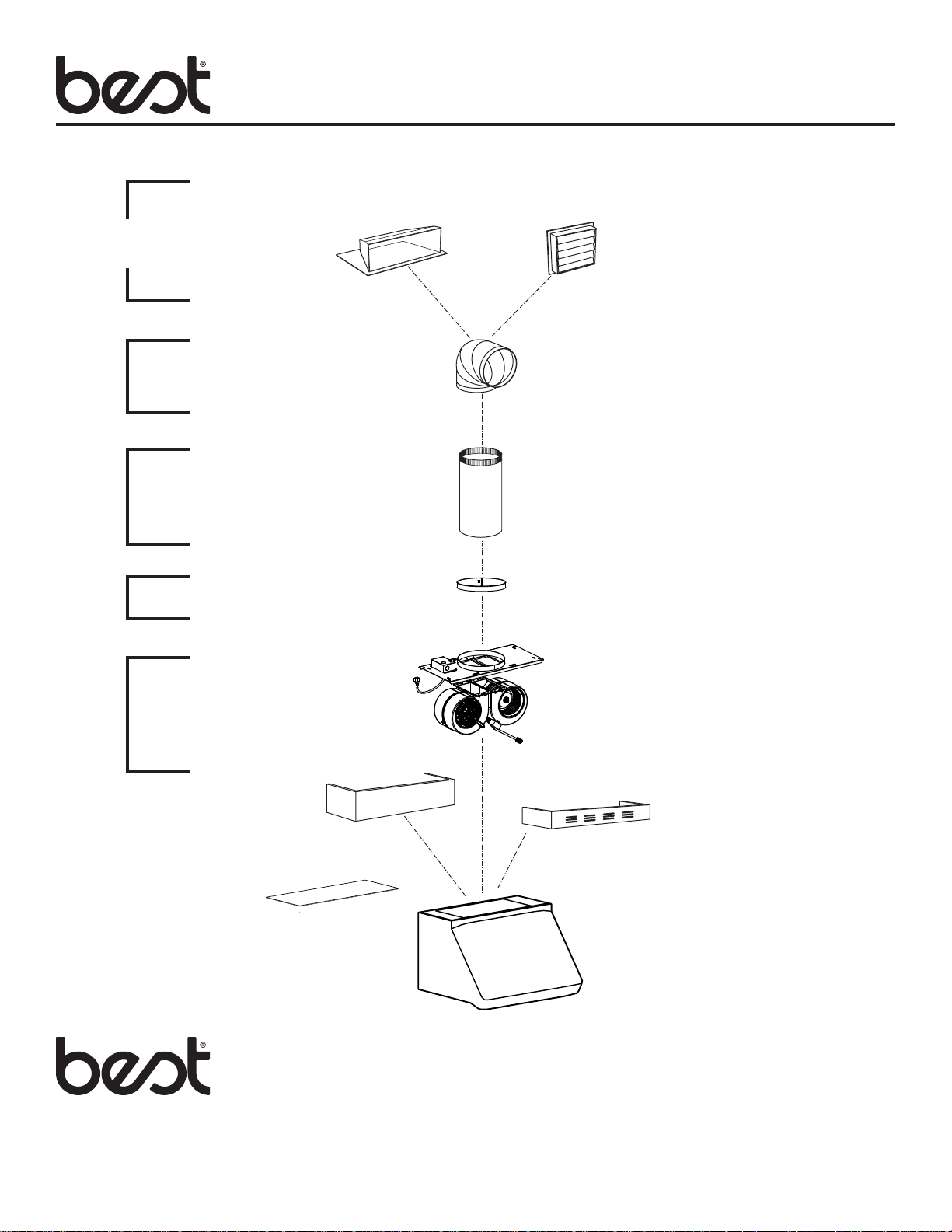
Wall & Roof Caps,
Exterior Blowers
Elbows
Ductwork
In-Line
Damper
MODEL 437
(High capacity roof cap)
MODEL 418
(10” round adjustable elbow)
MODEL 410
(10” round duct—2 ft. sections)
MODEL 421
(10” round In-Line Damper - included)
MODEL 441
(10’’ Round wall cap)
Blower
System
OPTIONAL
DECORATIVE FLUE
OPTIONAL
FLAT TOP COVER
ADPWP SERIES
(for WP29M Series
Hood Only)
MODEL P12
BLOWER/ROUGH-IN KIT
(1200 cfm interior blower
& rough-in plate)
NON-DUCT KIT FLUE
ANKWP SERIES
(for WP29M Series
Hood Only)
WP29M, IP29M, K260A
SERIES HOOD
(Canopy with
blower controls
& lighting.
Required for all
installations.)
INTERNAL BLOWER
RANGE HOOD SYSTEM
Page 3
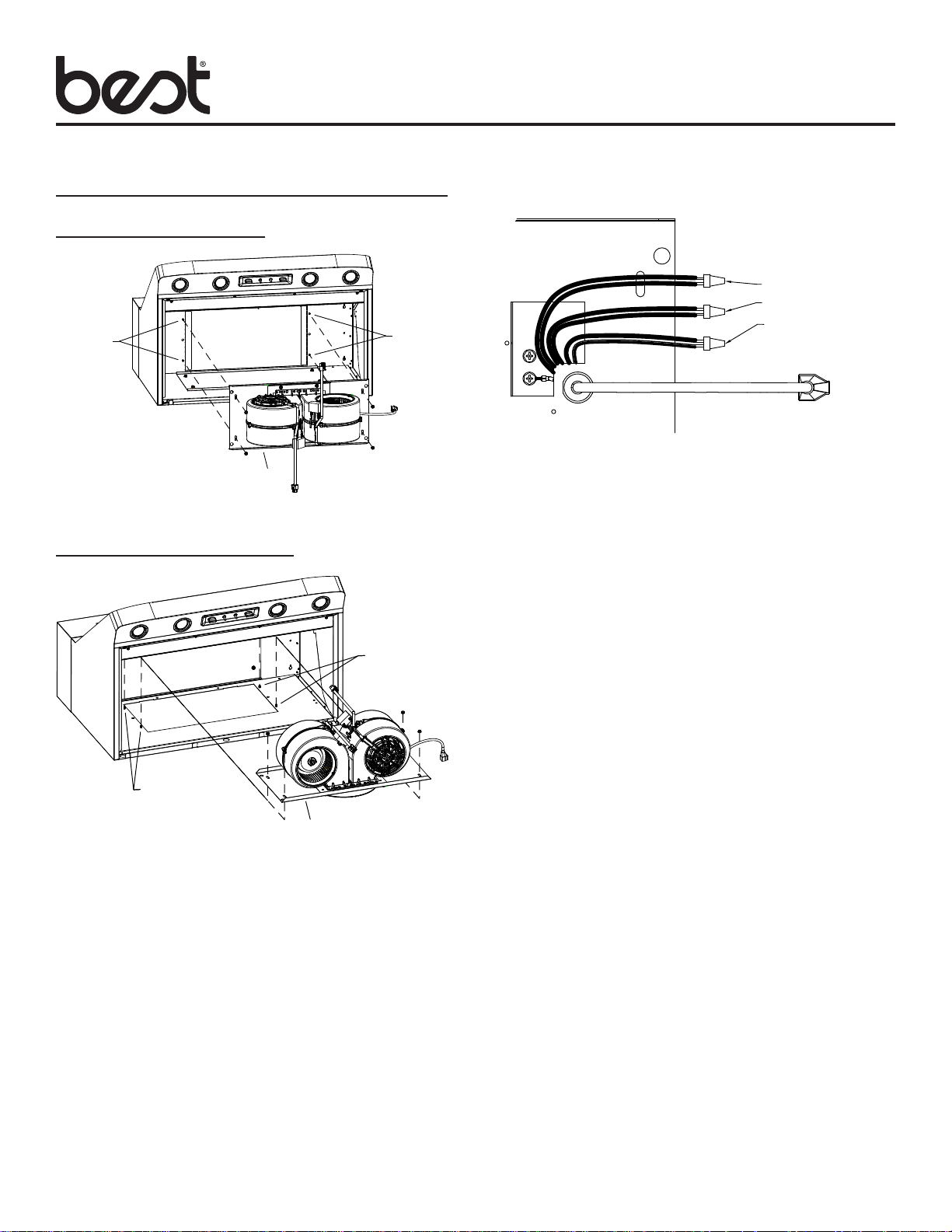
INSTALLATION
VERTICAL DISCHARGE
MOUNTING
STUDS
COVER PLATE
ROUGH-IN
PLATE
HORIZONTAL DISCHARGE
HEX
NUTS
MOUNTING
STUDS
MODEL P12
Page 3
ROUGH-IN PLATE
BLACK TO BLACK
WHITE TO WHITE
GREEN TO GREEN
OR BARE WIRE TO
GROUND SCREW
2. Remove wiring cover.
3. Run power cable to installation location, remove knockout
from ROUGH-IN PLATE wiring box and connect cable to wiring box using proper connector. Connect BLACK TO BLACK
(hot), WHITE TO WHITE (neutral) and GREEN OR BARE
WIRE (ground) under second ground screw. Replace wiring
cover.
COVER
PLATE
MOUNTING
STUDS
ROUGH-IN
PLATE
MOUNTING
STUDS
HEX
NUTS
1. Attach ROUGH-IN PLATE to MOUNTING STUDS at inside,
top of hood with (4) existing #10-32 HEX NUTS.
4. Run 10” round steel duct to installation location.
5. Install 10” round damper (included) inside ductwork, at least
3” above mounting plate
Page 4
MODEL P12
Page 4
MOUNTING
PLATE
BLOWERS
HEX NUTS (8)
6. Connect duct to rough-in plate. Use duct tape to make all
joints secure and air tight.
ROUGH-IN
PLATE
SLOTS
TABS
BLOWER /
MOUNTING
PLATE
ASSEMBLY
HEX NUTS (2)
STUDS
HOOD
RECEPTACLE
ROUGH-IN
PLATE
POWER
CORD
HOOD
RECEPTACLE
BLOWER
POWER
CORD
7. Attach BLOWERS to MOUNTING PLATE with (8) 10 -24 HEX
NUTS.
8. Engage two TABS on BLOWER / MOUNTING PLATE
ASSEMBLY into two SLOTS in ROUGH-IN PLATE. Secure
blower / mounting plate assembly to THREADED STUDS on
rough-in plate with (2) 10-24 HEX NUTS.
9. Plug BLOWER POWER CORD and ROUGH-IN PLATE
POWER CORD into HOOD RECEPTACLES.
10. Wrap wires with wire tie (provided).
Page 5
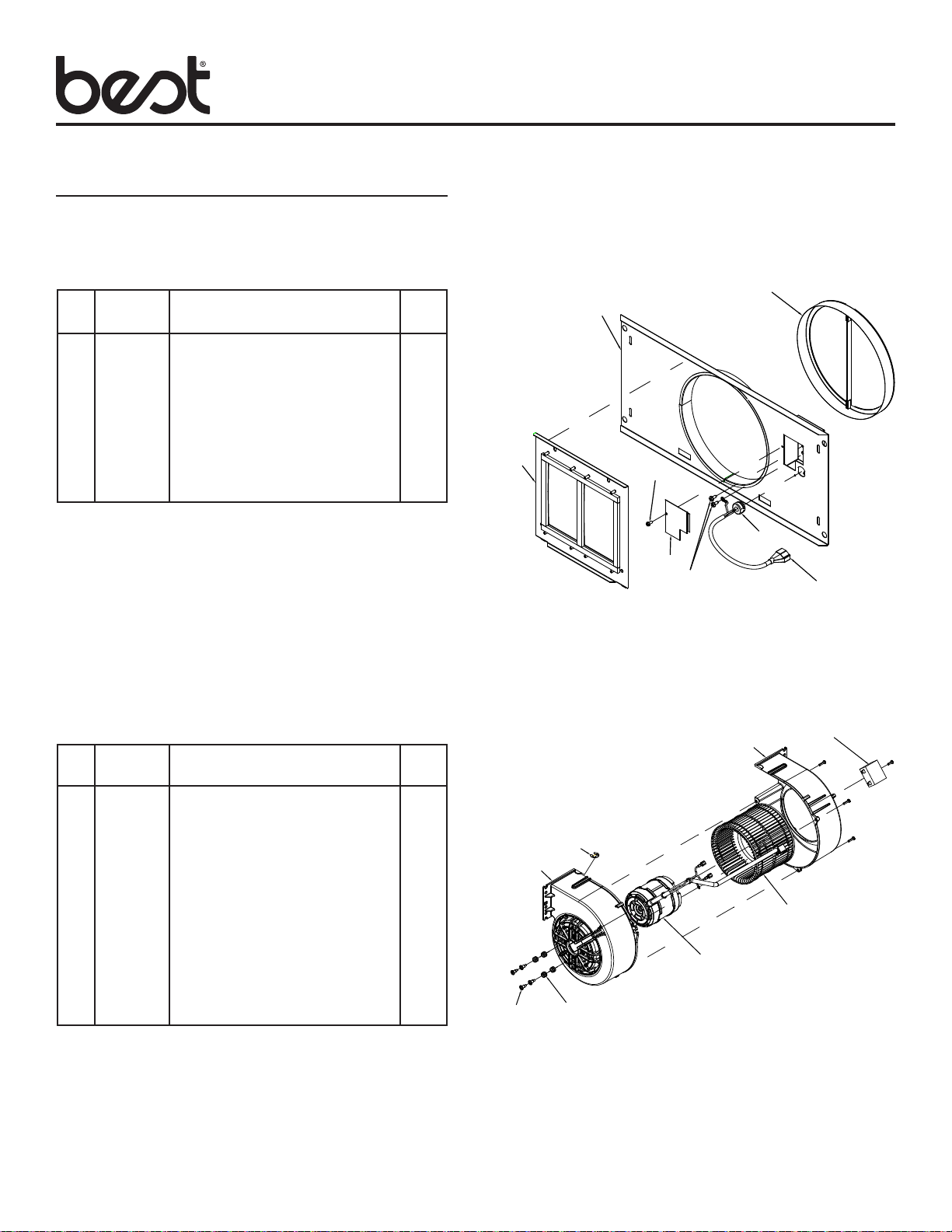
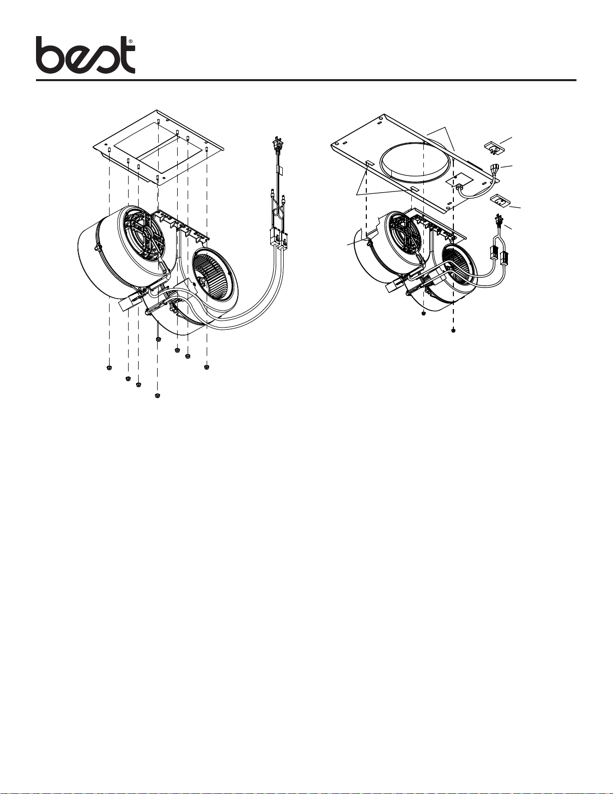
SERVICE PARTS
Model P12
MODEL P12
Page 5
ROUGH IN PLATE
KEY PART DESCRIPTION QTY
NO. NUMBER
1 97018167 ROUGH-IN PLATE WELDMENT 1
2 97018827 MOUNTING PLATE ASSEMBLY 1
3 99440033 POWER CORD 1
4 99150471 SCREW, #10-32 X 1/2 HEX
WASHER HEAD* 2
5 99400060 STRAIN RELIEF 1
6 98003370 OUTLET BOX COVER 1
7 99170245 SCREW, #8-18X3/8* 1
8 99580015 10” DAMPER 1
+ 97018823 ROUGH-IN KIT (COMPLETE)
+ NOT SHOWN
* STANDARD HARDWARE. MAY BE PURCHASED LOCALLY.
BLOWER
KEY PART DESCRIPTION QTY
NO. NUMBER
1 99111448 BLOWER HOUSING, MOTOR 1
2 99111447 BLOWER HOUSING, INLET 1
3 99271379 CAPACITOR 1
4 99020298 BLOWER WHEEL 1
5 99080629 MOTOR 1
6 GROMMET (CONTAINED IN
HARDWARE BAG) 4
7 SCREW, M4 X 16.8MM 4
8 SCREW, M4 X 0.7 X 16MM 3
9 SCREW, M4 X 0.7 X 12MM 1
10 RETAINING RING 1
+ 99770131 WIRE HARNESS 1
+ 97018828 HARDWARE BAG (CONTAINS
KEY NUMBERS 6-10) 1
+ 97017924 BLOWER (COMPLETE) 1
+ NOT SHOWN
2
7
8
1
7
5
6
4
2
10
1
5
6
3
3
4
Page 6

!
VENTILATEUR
INTERNE
MODÈLE P12
Page 6
À utiliser avec les hottes Best compatibles.
Voir dans le manuel de la hotte si le modèle convient.
AVERTISSEMENT
AFIN DE DIMINUER LES RISQUES D’INCENDIE,
D’ÉLECTROCUTION OU DE BLESSURES, SUIVEZ CES
DIRECTIVES :
1. N’utilisez cet appareil que de la manière prévue par le fabricant.
Si vous avez des questions, communiquez avec le fabricant à
l’adresse ou au numéro de téléphone indiqués dans la garantie.
2. Avant de procéder à la réparation ou à l’entretien de l’appareil,
coupez l’alimentation du panneau électrique et verrouillez le
dispositif de sectionnement de manière à empêcher que le
courant ne soit accidentellement rétabli. S’il est impossible de
verrouiller l’interrupteur principal, fixez solidement un message
d’avertissement, par exemple une étiquette, sur le panneau
électrique.
3. L’installation et les branchements électriques doivent être
effectués par un personnel compétent, conformément aux
normes et aux codes en vigueur, y compris les normes et les
codes du bâtiment relatifs à la résistance au feu.
4. Pour éviter les refoulements, l’apport d’air doit être suffisant
pour brûler les gaz produits par les appareils à combustion et
les évacuer dans le conduit de fumée (cheminée). Respectez
les directives du fabricant de l’appareil de chauffage et
les normes de sécurité, notamment celles publiées par la
National Fire Protection Association (NFPA), l’American Society
for Heating, Refrigeration and Air Conditioning Engineers
(ASHRAE) et les codes des autorités locales.
5. Veillez à ne pas endommager le câblage électrique ou d’autres
équipements non apparents lors de la découpe ou du perçage
du mur ou du plafond.
6. Les ventilateurs canalisés doivent toujours rejeter l’air à
l’extérieur.
7. N’utilisez pas de commande de régime à semi-conducteurs
conjointement avec cet appareil.
8. Pour réduire les risques d’incendie, utilisez seulement des
conduits en acier.
9. Cet appareil doit être relié à une mise à la terre.
POUR RÉDUIRE LES RISQUES D’INCENDIE CAUSÉS PAR
DE LA GRAISSE SUR LE PLAN DE CUISSON :
a) Ne laissez jamais les éléments de surface allumés à haute
température. Les débordements peuvent causer de la fumée
et occasionner des écoulements de graisse inflammables.
L’huile doit être chauffée graduellement à basse ou à moyenne
température.
b) Mettez toujours la hotte en marche lors de la cuisson à haute
température ou lors de la cuisson d’aliments à flamber.
c) Nettoyez souvent la hotte. Ne laissez pas la graisse s’accumuler
sur le ventilateur ou les filtres.
d) Utilisez des casseroles de dimension appropriée. Utilisez
toujours une batterie de cuisine adaptée à la dimension de la
surface chauffante.
AVERTISSEMENT
OBSERVEZ LES CONSIGNES SUIVANTES AFIN DE RÉDUIRE
LES RISQUES DE BLESSURES CORPORELLES EN CAS
D’INCENDIE CAUSÉ PAR DE LA GRAISSE SUR LE PLAN
DE CUISSON :*
1. ÉTOUFFEZ LES FLAMMES à l’aide d’un couvercle étanche,
d’une tôle à biscuits ou d’un plateau en métal puis éteignez le
brûleur. FAITES ATTENTION DE NE PAS VOUS BRÛLER. SI
LES FLAMMES NE S’ÉTEIGNENT PAS IMMÉDIATEMENT,
QUITTEZ LES LIEUX ET APPELEZ LE SERVICE DES
INCENDIES.
2. NE SOULEVEZ JAMAIS UNE CASSEROLE EN FLAMMES–
vous pourriez vous brûler.
3. N’UTILISEZ PAS D’EAU, ni de linges ou de serviettes
mouillés– une violente explosion de vapeur pourrait survenir.
4. Utilisez un extincteur SEULEMENT si :
A. Vous savez qu’il est de classe ABC et vous connaissez déjà
son mode de fonctionnement.
B. L’incendie n’est pas très important et ne se propage pas.
C. Vous avez déjà téléphoné au service des incendies.
D. Vous pouvez combattre l’incendie en faisant dos à une sortie.
* Conseils tirés de la publication de la NFPA « Kitchen Fire Safety
Tips ».
ATTENTION
1. Pour ventilation générale uniquement. Ne pas utiliser
cet appareil pour évacuer des matières ou des vapeurs
dangereuses ou explosives.
2. Pour éviter d’endommager les roulements de moteur, de
déséquilibrer les pales ou de les rendre bruyantes, débarrassez
l’appareil de la poussière de plâtre, de construction, etc.
3. Le moteur de ventilateur est muni d’un dispositif de protection
de surcharge électrique qui le met automatiquement hors
fonction en cas de surchauffe. Il se remet en marche lorsqu’il
a refroidi. Faites réparer la hotte si le moteur continue à
fonctionner par intermittence.
4. Veuillez lire l’étiquette de spécifications du produit pour obtenir
plus de renseignements, notamment sur les exigences.
5. Pour réduire les risques d’incendie et obtenir une évacuation
adéquate de l’air dans le cas d’une installation canalisée,
acheminez les conduits jusqu’à l’air libre – n’évacuez pas l’air
dans des interstices entre les murs ou le plafond, ni dans un
grenier, un vide sanitaire ou un garage.
INSTALLATEUR :
Conservez ce manuel pour l’inspection
électrique et le propriétaire.
Page 7

MODÈLE P12
Page 7
Capuchon mural et de toit,
ventilateurs extérieurs
Coudes
Conduit
Clapet sur
conduit
MODÈLE 437
(capuchon de toit – grande capacité)
MODÈLE 418
(coude rond ajustable
de 25 cm [10 po])
MODÈLE 410
(conduit rond de
25 cm [10 po] —
sections de 61 cm [2 pi])
MODÈLE 421
(clapet sur conduit rond
de 25 cm [10 po] - inclus)
MODÈLE 441
(capuchon mural rond de 25 cm [10 po])
Système de
ventilateur
CONDUIT
DÉCORATIF FACULTATIF
COUVERCLE
SUPÉRIEUR PLAT
FACULTATIF
SÉRIE ADPWP
(pour hotte de série
WP29M seulement)
SYSTÈME DE HOTTE
MODÈLE P12
ENSEMBLE ENCASTRABLE
DE VENTILATEUR
(ventilateur intérieur de 1200 pi
et plaque de raccordement)
ENSEMBLE DE CONDUIT
NON CANALISÉ
SÉRIE ANKWP
(pour hotte de série
WP29M seulement)
HOTTE DE SÉRIE WP29M,
IP29M, K260A
(capot avec commandes de
ventilation et d'éclairage)
Requis pour toutes
les installations.)
3
/min.
À VENTILATEUR INTERNE
Page 8

INSTALLATION
MODÈLE P12
Page 8
ÉVACUATION VERTICALE
GOUJONS
DE MONTAGE
PLAQUE DE FERMETURE
PLAQUE
DE JONCTION
ÉVACUATION HORIZONTALE
PLAQUE DE
FERMETURE
GOUJONS
DE MONTAGE
ÉCROUS
HEXAGONAUX
GOUJONS
DE MONTAGE
ÉCROUS
HEXAGONAUX
PLAQUE DE
RACCORDEMENT
NOIR AVEC NOIR
BLANC AVEC BLANC
CONNECTEZ LE FIL VERT
OU LE FIL DÉNUDÉ À LA VIS
DE MISE À LA TERRE
2. Retirez le couvercle du boîtier de câblage.
3. Faites cheminer les câbles vers l’emplacement de pose.
Retirez l’entrée sectionnable de la plaque de raccordement
du boîtier de câblage et branchez le câble au boîtier de
câblage en utilisant le connecteur approprié. Branchez
les FILS NOIRS ENSEMBLE (tension), les FILS BLANCS
ENSEMBLE (neutre) et placez le fil VERT ou le fil DÉNUDÉ
(terre) sous la deuxième vis de mise à la terre. Replacez le
couvercle du boîtier de câblage.
4. Faites cheminer les conduits ronds en acier de 25 cm (10po)
vers l’emplacement de pose.
5. Installez le clapet rond de 25 cm (10 po) (inclus) à l’intérieur
du conduit, au moins 7,6 cm (3 po) au-dessus de la plaque
demontage.
GOUJONS
DE MONTAGE
PLAQUE DE
JONCTION
1. Fixez la PLAQUE DU VENTILATEUR aux GOUJONS DE
MONTAGE à l’intérieur de la hotte à l’aide des quatre (4)
existantes écrous hexagonaux no° 10-32.
Page 9

MODÈLE P12
Page 9
PLAQUE DE
MONTAGE
VENTILATEURS
ÉCROUS HEXAGONAUX (8)
6. Raccordez le conduit à la plaque de raccordement. Utilisez
du ruban pour conduit afin de fixer solidement tous les joints
et assurer leur étanchéité.
PLAQUE DE
RACCORDEMENT
GOUJONS
FENTES
ERGOTS
ENSEMBLE
DE VENTILATEUR /
PLAQUE DE
MONTAGE
ÉCROUS HEXAGONAUX (2)
RÉCEPTACLE
DE HOTTE
CORDON
ÉLECTRIQUE
DE LA
PLAQUE DE
RACCORDEMENT
RÉCEPTACLE
DE HOTTE
CORDON
ÉLECTRIQUE
DU VENTILATEUR
7. Fixez les ventilateurs à la plaque de montage avec huit (8)
ÉCROUS HEXAGONAUX 10-24.
8. Engagez deux ERGOTS de l’ensemble VENTILATEUR /
PLAQUE DE MONTAGE dans les FENTES de la PLAQUE
DE RACCORDEMENT. Fixez l’ensemble de ventilateur/
plaque de montage sur les GOUJONS FILETÉS de
la plaque de raccordement avec deux (2) ÉCROUS
HEXAGONAUX10-24.
9. Branchez le CORDON ÉLECTRIQUE DU VENTILATEUR
et FIL DE LA PLAQUE DE RACCORDEMENT au les
RÉCEPTACLES DE HOTTE.
10. Groupez les fils avec l’attache (fournie).
Page 10

PIÈCES DE RECHANGE
Model P12
MODÈLE P12
Page 10
PLAQUE DE RACCORDEMENT
R EPÈRE N° DE DESCRIPTION QTÉ
PIÈCE
1 97018167 PLAQUE DE RACCORDEMENT SOUDÉE 1
2 97018827 ENSEMBLE DE PLAQUE DE MONTAGE 1
3 99440033 CORDON ÉLECTRIQUE 1
4 99150471 VIS, N° 10-32 X 1/2 TÊTE HEXAGONALE
À RONDELLE* 2
5 99400060 BRIDE DE CORDON 1
6 98003370 COUVERCLE DE BOÎTE ÉLECTRIQUE 1
7 99170245 VIS, N° 8-18 X 3/8* 1
8 99580015 CLAPET 25 CM (10 PO) 1
+ 97018823 ENSEMBLE ENCASTRABLE (COMPLET)
+ NON ILLUSTRÉ
* MATÉRIEL STANDARD. EN VENTE DANS UNE QUINCAILLERIE
PRÈS DE CHEZ VOUS.
VENTILATEUR
REPÈRE N° DE DESCRIPTION QTÉ
PIÈCE
1 99111448 BOÎTIER DE VENTILATEUR, MOTEUR 1
2 99111447 BOÎTIER DE VENTILATEUR, ENTRÉE 1
3 99271379 CONDENSATEUR 1
4 99020298 ROUE À AILETTES 1
5 99080629 MOTEUR 1
6 PASSE-FIL (CONTENU DANS LE SAC
DE QUINCAILLERIE) 4
7 VIS, M4 X 16,8 MM 4
8 VIS, M4 X 0,7 X 16 MM 3
9 VIS, M4 X 0,7 X 12 MM 1
10 ANNEAU DE COMPRESSION 1
+ 99770131 HARNAIS DE FIL 1
+ 97018828 SAC DE QUINCAILLERIE (CONTIENT
LES PIÈCES N
+ 97017924 VENTILATEUR (COMPLET) 1
+ NON ILLUSTRÉ
OS
6 À 10) 1
2
7
8
1
7
5
6
4
2
10
1
5
6
3
3
4
Page 11

VENTILADOR
!
INTERNO
MODELO P12
Página 11
Para usarse con campanas de estufa
compatibles de Best.
Consulte el manual de la campana para su idoneidad.
ADVERTENCIA
PARA REDUCIR EL RIESGO DE INCENDIO, DESCARGA
ELÉCTRICA O LESIONES PERSONALES, OBSERVE LO
SIGUIENTE:
1. Use la unidad solo de la manera indicada por el fabricante.
2. Si tiene preguntas, comuníquese con el fabricante a la dirección
o al número telefónico que se incluye en la garantía. Antes
de dar servicio o limpiar la unidad, interrumpa el suministro
eléctrico en el panel de servicio y bloquee los medios de
desconexión del servicio para evitar que la electricidad sea
reanudada accidentalmente. Cuando no sea posible bloquear
los medios de desconexión del servicio, fije firmemente una
señal de advertencia (como una etiqueta) en un lugar visible
del panel de servicio.
3. Solo personal calificado debe realizar el trabajo de instalación
y el cableado eléctrico, de acuerdo con todos los códigos y las
normas correspondientes, incluidos los códigos y las normas
de construcción específicos sobre protección contra incendios.
4. Es necesario suficiente aire para que se lleve a cabo una
combustión y una extracción adecuadas de los gases a
través del tubo de humos (chimenea) del equipo quemador
de combustible, con el fin de evitar el contratiro. Siga las
directrices y las normas de seguridad del fabricante del equipo
de calefacción, como las publicadas por la Asociación Nacional
de Protección contra Incendios (National Fire Protection
Association, NFPA), y la Sociedad Americana de Ingenieros
en Calefacción, Refrigeración y Aire Acondicionado (American
Society for Heating, Refrigeration and Air Conditioning
Engineers, ASHRAE), y las autoridades de los códigos locales.
5. Al cortar o perforar a través de la pared o del techo, tenga
cuidado de no dañar el cableado eléctrico ni otros servicios
ocultos.
6. Los ventiladores en conductos siempre deben ventearse hacia
el exterior.
7. No use esta campana de estufa junto con ningún dispositivo
adicional de estado sólido para el control de la velocidad.
8. Para reducir el riesgo de incendio, use solamente conductos
de acero.
9. Esta unidad debe estar conectada a tierra.
PARA REDUCIR EL RIESGO DE INCENDIO PROVOCADO
POR GRASA PRESENTE EN LA ESTUFA:
a) Nunca deje desatendidas las unidades de la superficie cuando
estén en ajustes altos de calor. Los alimentos en ebullición
provocan derrames grasosos y con humo que se pueden
incendiar. Caliente el aceite lentamente en ajustes de calor
bajo o medio.
b) Siempre ENCIENDA la campana cuando cocine con calor alto
o cuando cocine alimentos inflamables.
c) Limpie frecuentemente los ventiladores. No permita la
acumulación de grasa en el ventilador ni en el filtro.
d) Use una cacerola del tamaño adecuado. Siempre use utensilios
de cocina que sean apropiados para el tamaño del elemento
de la superficie.
ADVERTENCIA
PARA REDUCIR EL RIESGO DE LESIONES PERSONALES EN
EL CASO DE QUE LA GRASA DE LA ESTUFA SE INCENDIE,
SIGA LAS SIGUIENTES PRECAUCIONES*:
1. APAGUE LAS LLAMAS con una tapa de ajuste exacto, una
charola para galletas o una bandeja de metal, y después
apague el quemador. PROCEDA CON CUIDADO PARA
EVITAR QUEMADURAS. SI LAS LLAMAS NO SE APAGAN
INMEDIATAMENTE, EVACÚE EL ÁREA Y LLAME AL
DEPARTAMENTO DE BOMBEROS.
2. NUNCA LEVANTE UNA CACEROLA INCENDIADA, se puede
quemar.
3. NO USE AGUA ni toallas húmedas, ya que provocará una
violenta explosión de vapor.
4. Use un extintor SOLO si:
A. El extintor es clase ABC y usted sabe cómo usarlo.
B. El incendio es pequeño y está confinado al área en la que se
inició.
C. Se ha llamado al departamento de bomberos.
D. Puede combatir el incendio teniendo la espalda orientada hacia
una salida.
* Basado en “Kitchen Fire Safety Tips” (Sugerencias para la
seguridad contra incendios en la cocina) publicado por NFPA.
PRECAUCIÓN
1. Solo para usarse como medio de ventilación general. No debe
usarse para la extracción de materiales o vapores peligrosos
o explosivos.
2. Para evitar daños a los cojinetes del motor y rotores ruidosos
o desbalanceados, mantenga la unidad de potencia protegida
contra rociados de yeso, polvos de construcción, etc.
3. Este ventilador tiene una protección contra sobrecargas
térmicas que automáticamente apagará el motor en caso de
sobrecalentamiento. El motor reanudará su funcionamiento
cuando se enfríe. Si el motor continúa apagándose y
encendiéndose, solicite servicio para la campana.
4. Lea la etiqueta de especificaciones del producto para ver
información y requisitos adicionales.
5. Para reducir el riesgo de incendio y para descargar
adecuadamente el aire en una instalación con conductos,
asegúrese de dirigir el aire hacia el exterior. No descargue el
aire hacia espacios contenidos entre paredes o cielos rasos,
ni hacia áticos, sótanos bajos ni la cochera.
INSTALADOR:
Conserve este manual para que lo use el
inspector eléctrico y el propietario.
Page 12

MODELO P12
Página 12
Tapas de pared y techo,
ventiladores exteriores
Codos
Sistema
de tubería
Regulador
de tiro
en línea
MODELO 437
(tapa de techo de alta capacidad)
MODELO 418
(codo redondo ajustable
de 10 pulg. [25cm])
MODELO 410
(conducto redondo de
10 pulg. [25 cm] –
secciones de 2 pies [61 cm])
MODELO 421
(regulador de tiro en línea
de 10 pulg. [25 cm] - incluido)
MODELO 441
(tapa de pared redonda de 10 pulg. [25 cm])
Sistema de
ventilación
TUBO DE HUMOS
DECORATIVO OPCIONAL
CUBIERTA
SUPERIOR PLANA
OPCIONAL DE
LA SERIE ADPWP
(para campana de la
serie WP29M solamente)
MODELO P12
JUEGO DE VENTILADOR/EMPALME
(ventilador interno de 1200 pcm
y placa de empalme)
JUEGO DE TUBO DE HUMOS
SIN CONDUCTOS DE
LA SERIE ANKWP
(para campana de la
serie WP29M solamente)
CAMPANA DE
LA SERIE WP29M,
IP29M, K260A
(Se requiere cubierta
con controles del
ventilador e iluminación
en todas las instalaciones)
SISTEMA DE CAMPANA DE
ESTUFA CON VENTILADOR INTERNO
Page 13

INSTALACIÓN
DESCARGA VERTICAL
MONTANTES
DE MONTAJE
PLACA DE CUBIERTA
MONTANTES
DE MONTAJE
TUERCAS
HEXAGONALES
MODELO P12
Página 13
PLACA DE EMPALME
NEGRO A NEGRO
BLANCO A BLANCO
VERDE A VERDE O
SIN FORRO AL
TORNILLO DE TIERRA
PLACA DE
EMPALME
DESCARGA HORIZONTAL
PLACA DE
CUBIERTA
MONTANTES
DE MONTAJE
PLACA DE
EMPALME
1. Fije la PLACA DE EMPALME a los MONTANTES DE
MONTAJE de la parte superior interna de la campana con
cuatro (4) TUERCAS HEXAGONALES #10-32 existentes.
MONTANTES
DE MONTAJE
TUERCAS
HEXAGONALES
2. Quite la cubierta de la conexión eléctrica.
3. Haga pasar el cable eléctrico al sitio de la instalación, quite
el agujero ciego de la caja de cableado de la PLACA DE
EMPALME y conecte el cable a la caja de cableado con
el conector adecuado. Conecte NEGRO A NEGRO (vivo),
BLANCO A BLANCO (neutro) y VERDE O SIN FORRO
(tierra) debajo del segundo tornillo de puesta a tierra. Vuelva
a colocar la cubierta de la conexión eléctrica.
4. Coloque el conducto de acero redondo de 10 pulg. (25 cm)
en el sitio de la instalación.
5. Instale un regulador redondo de 10 pulg. (25 cm) (incluido)
dentro de los conductos, por lo menos a 3 pulg. (7.6 cm)
arriba de la placa de montaje.
Page 14

MODELO P12
Página 14
PLACA DE
MONTAJE
VENTILADORES
TUERCAS HEXAGONALES (8)
6. Conecte el conducto a la placa de empalme. Use cinta para
conductos para fijar y sellar todas las uniones.
PLACA DE
EMPALME
RANURAS
LENGÜETAS
CONJUNTO
DE PLACA DE
MONTAJE/
VENTILADOR
TUERCAS HEXAGONALES (2)
MONTANTES
RECEPTACULO
DE CAMPANA
CABLE
ELÉCTRICO
DE LA PLACA
DE EMPALME
RECEPTACULO
DE CAMPANA
CABLE
ELÉCTRICO
DEL
VENTILADOR
7. Fije los VENTILADORES a la PLACA DE MONTAJE con
ocho (8) TUERCAS HEXAGONALES 10-24.
8. Enganche las dos LENGÜETAS del CONJUNTO DE PLACA
DE MONTAJE/VENTILADOR en las dos LENGÜETAS
de la PLACA DE EMPALME. Fije el conjunto de placa de
montaje/ventilador a los PERNOS ROSCADOS de la placa
de empalme con dos (2) TUERCAS HEXAGONALES 10-24.
9. Conecte el CABLE ELÉCTRICO DEL VENTILADOR y
CABLE ELÉCTRICO DE LA PLACA DE EMPLAME en los
RECEPTACULOS DE CAMPANA.
10. Amarre los cables con la atadura para cables provista.
Page 15

PIEZAS DE SERVICIO
Modelo P12
MODELO P12
Página 15
PLACA DE EMPALME
C LAVE NÚMERO DESCRIPCIÓN CDAD.
N.º DE PIEZA
1 97018167 ESTRUCTURA SOLDADA DE LA PLACA
DE EMPALME 1
2 97018827 CONJUNTO DE LA PLACA DE MONTAJE 1
3 99440033 CABLE ELÉCTRICO 1
4 99150471 TORNILLO, CABEZA DE ARANDELA
HEXAGONAL #10-32 X 1/2* 2
5 99400060 ALIVIO DE TENSIÓN 1
6 98003370 CUBIERTA DE LA CAJA DE SALIDA 1
7 99170245 TORNILLO, #8-18X3/8* 1
8 99580015 REGULADOR DE TIRO DE 10 PULG. (25 CM) 1
+ 97018823 JUEGO DE EMPALME (COMPLETO)
+ NO SE MUESTRA
* TORNILLERÍA ESTÁNDAR. SE PUEDE COMPRAR EN
UNA FERRETERÍA LOCAL.
VENTILADOR
CLAVE NÚMERO DESCRIPCIÓN CDAD.
N.º DE PIEZA
1 99111448 CAJA DEL VENTILADOR, MOTOR 1
2 99111447 CAJA DEL VENTILADOR, ENTRADA 1
3 99271379 CAPACITOR 1
4 99020298 RUEDA DEL VENTILADOR 1
5 99080629 MOTOR 1
6 ARANDELA DE HULE (SE ENCUENTRA
EN LA BOLSA DE TORNILLERÍA) 4
7 TORNILLO, M4 X 16.8 MM 4
8 TORNILLO, M4 X 0.7 MM X 16 MM 3
9 TORNILLO, M4 X 0.7 MM X 12 MM 1
10 ANILLO DE RETENCIÓN 1
+ 99770131 ARNESES DE CABLES 1
+ 97018828 BOLSA DE TORNILLERÍA (CONTIENE
LOS N.
+ 97017924 VENTILADOR (COMPLETO) 1
+ NO SE MUESTRA
OS
DE CLAVE 6-10) 1
2
7
8
1
7
5
6
4
2
10
1
5
6
3
3
4
Page 16

MODEL / MODÈLE / MODELO P12
WARRANTY / GARANTIE / GARANTÍA
ONE YEAR LIMITED WARRANTY FOR BEST PRODUCTS
Broan-NuTone LLC (Broan-NuTone) warrants to the original consumer purchaser of Best products that such products will be free from defects in materials or workmanship
for a period of one year from the date of original purchase. THERE ARE NO OTHER WARRANTIES, EXPRESS OR IMPLIED, INCLUDING, BUT NOT LIMITED TO, IMPLIED
WARRANTIES OR MERCHANT ABILITY OR FITNESS FOR A PARTICULAR PURPOSE.
During this one-year period, Broan-NuTone will, at its option, repair or replace, without charge, any product or part which is found to be defective under normal use and service.
THIS WARRANTY DOES NOT EXTEND TO FLUORESCENT LAMP STARTERS, TUBES, HALOGEN AND INCANDESCENT BULBS, FUSE, FILTERS, DUCTS, ROOF CAPS, WALL
CAPS AND OTHER ACCESSORIES FOR DUCTING. This warranty does not cover (a) normal maintenance and service or (b) any products or parts which have been subject
to misuse, negligence, accident, improper maintenance or repair (other than by Broan-NuTone), faulty installation or installation contrary to recommended installation
instructions.
The duration of any implied warranty is limited to the one-year period as specified for the express warranty. Some states do not allow limitation on how long an implied
warranty lasts, so the above limitation may not apply to you.
BROAN-NUTONE’S OBLIGATION TO REPAIR OR REPLACE, AT BROAN-NUTONE’S OPTION, SHALL BE THE PURCHASER’S SOLE AND EXCLUSIVE REMEDY UNDER
THIS WARRANTY. BROAN-NUTONE SHALL NOT BE LIABLE FOR INCIDENTAL, CONSEQUENTIAL OR SPECIAL DAMAGES ARISING OUT OF OR IN CONNECTION WITH
PRODUCT USE OR PERFORMANCE. Some states do not allow the exclusion or limitation of incidental or consequential damages, so the above limitation or exclusion
may not apply to you.
This warranty gives you specific legal rights, and you may also have other rights, which vary from state to state. This warranty supersedes all prior warranties.
To qualify for warranty service, you must (a) notify Broan-NuTone at the address or telephone number stated below, (b) give the model number and part identification and
(c) describe the nature of any defect in the product or part. At the time of requesting warranty service, you must present evidence of the original purchase date.
In USA - BEST® Hartford, Wisconsin 800-558-1711
In Canada - BEST® Drummondville, QC 866-737-7770
www.BestRangeHoods.com
GARANTIE LIMITÉE D’UN AN DES PRODUITS BEST
Broan-NuTone LLC (Broan-NuTone) garantit à l’acheteur original que les produits Best sont libres de tout vice de matériau ou de fabrication pour une période d’un an à
compter de la date d’achat originale. CETTE GARANTIE NE COMPORTE AUCUNE AUTRE GARANTIE, EXPRESSE OU TACITE, Y COMPRIS, MAIS SANS S’Y LIMITER, LES
GARANTIES TACITES DE VALEUR MARCHANDE OU D’ADAPTATION À UN USAGE PARTICULIER.
Durant cette période d’un an, Broan-NuTone réparera ou remplacera gratuitement, à sa discrétion, tout produit ou toute pièce jugés défectueux dans des conditions
normales d’utilisation.
CETTE GARANTIE NE S’APPLIQUE PAS AUX TUBES FLUORESCENTS ET AUX DÉMARREURS, NI AUX AMPOULES HALOGÈNES OU INCANDESCENTES, FUSIBLES, FILTRES,
CONDUITS, CAPUCHONS DE TOIT, CAPUCHONS MURAUX ET AUTRES ACCESSOIRES POUR CONDUITS. Cette garantie ne couvre pas (a) les frais d’entretien ou de
service normaux ni (b) tout produit ou toute pièce soumis à un abus, une négligence, un accident, un entretien ou une réparation inadéquats (autres que ceux effectués
par Broan-NuTone), une mauvaise installation ou une installation contraire aux instructions recommandées.
La durée de toute garantie tacite est limitée à la période d’un an stipulée pour la garantie expresse. Certains territoires ou provinces interdisant de limiter la durée d’une
garantie tacite, la limitation ci-dessus peut ne pas s’appliquer à votre situation.
L’OBLIGATION POUR BROAN-NUTONE DE RÉPARER OU DE REMPLACER LE PRODUIT, À SA DISCRÉTION, CONSTITUE LE SEUL RECOURS DE L’ACHETEUR EN VERTU
DE LA PRÉSENTE GARANTIE. BROAN-NUTONE NE PEUT ÊTRE TENUE RESPONSABLE DES DOMMAGES INDIRECTS OU CONSÉCUTIFS NI DES DOMMAGES-INTÉRÊTS
PARTICULIERS DÉCOULANT DE L’UTILISATION OU DU RENDEMENT DU PRODUIT. Certains territoires ou provinces ne permettant pas la limitation ou l’exclusion des
dommages indirects ou consécutifs, la limitation ci-dessus peut ne pas s’appliquer à votre situation.
La présente garantie vous confère des droits spécifiques reconnus par la loi. D’autres droits pourraient également vous être accordés selon la législation locale en vigueur.
La présente garantie remplace toutes les autres garanties précédentes.
Pour vous prévaloir de cette garantie, vous devez (a) aviser Broan-NuTone à l’adresse ou au numéro de téléphone indiqués ci-dessous, (b) donner le numéro de modèle
du produit et le numéro d’identification de la pièce et (c) décrire la nature de la défectuosité du produit ou de la pièce. Lors de votre demande de garantie, vous devez
présenter une preuve de la date d’achat originale.
Aux États-Unis - BEST® Hartford, Wisconsin 800-558-1711
Au Canada - BEST® Drummondville, QC 866-737-7770
www.BestRangeHoods.com
Page / Página 16
Broan-NuTone LLC (Broan-NuTone) garantiza al consumidor comprador original de los productos BEST que tales productos estarán libres de defectos en materiales o
mano de obra durante un período de un año a partir de la fecha de la compra original. NO EXISTEN OTRAS GARANTÍAS, EXPRESAS NI IMPLÍCITAS, INCLUIDAS (PERO
SIN LIMITARSE A) GARANTÍAS IMPLÍCITAS DE COMERCIALIZACIÓN O IDONEIDAD PARA UN PROPÓSITO PARTICULAR.
Durante este período de un año, Broan-NuTone, a su criterio, reparará o reemplazará sin cargo alguno cualquier pieza o producto que se encuentre defectuoso bajo
condiciones normales de uso y servicio.
LA PRESENTE GARANTÍA NO CUBRE ARRANCADORES DE LÁMPARAS FLUORESCENTES, TUBOS, BOMBILLAS HALÓGENAS E INCANDESCENTES, FUSIBLES, FILTROS,
CONDUCTOS, TAPAS DE TECHO O DE PARED Y DEMÁS ACCESORIOS DE CANALIZACIÓN. Esta garantía no cubre (a) mantenimiento y servicio normales, ni (b) ningún
producto o piezas que se hayan sometido a uso inadecuado, negligencia, accidente, mantenimiento o reparación inadecuada (no hecha por Broan-NuTone), instalación
incorrecta o instalación en contra de las instrucciones de instalación recomendadas.
La duración de cualquier garantía implícita se limita a un período de un año, como se especifica en la garantía expresa. Algunos estados no permiten limitaciones en cuanto
al tiempo de vencimiento de una garantía implícita, por lo que la limitación antes mencionada podría no aplicarse a usted.
LA OBLIGACIÓN DE BROAN-NUTONE DE REPARAR O REEMPLAZAR, A CRITERIO DE BROAN-NUTONE, SERÁ EL ÚNICO Y EXCLUSIVO RECURSO DEL COMPRADOR
BAJO ESTA GARANTÍA. BROAN-NUTONE NO SERÁ RESPONSABLE POR DAÑOS INCIDENTALES, RESULTANTES O ESPECIALES QUE SURJAN DEL USO O DESEMPEÑO
DEL PRODUCTO O EN RELACIÓN CON EL MISMO. Algunos estados no permiten la exclusión o limitación de daños incidentales o resultantes, por lo que la limitación
antes mencionada podría no aplicarse a usted.
Esta garantía le otorga derechos legales específicos, y usted podría tener otros derechos que varían de un estado a otro. Esta garantía sustituye todas las garantías anteriores.
Para tener derecho al servicio de la garantía, usted debe (a) notificar a Broan-NuTone a la dirección y número de teléfono que aparecen abajo, (b) proporcionar el número
de modelo y la identificación de la pieza y (c) describir la naturaleza de cualquier defecto en el producto o pieza. En el momento de solicitar el servicio cubierto por la
garantía, debe presentar un comprobante de la fecha original de compra.
En EE. UU. – BEST® Hartford, Wisconsin 800-558-1711
En Canadá - BEST® Drummondville, QC 866-737-7770
www.BestRangeHoods.com
GARANTÍA LIMITADA DE UN AÑO PARA LOS PRODUCTOS BEST
99044870E
 Loading...