

Page 1

INSTRUCTIONS FOR INSTALLATION AND USE
MONTAGE- UND GEBRAUCHSANWEISUNG
INSTRUCTIONS POUR L'INSTALLATION ET L’UTILISATION
ISTRUZIONI PER L'INSTALLAZIONE E L’USO
INSTRUCCIONES PARA INSTALACIÓN Y USO
INSTRUÇÕES DE INSTALAÇÃO Y UTILIZAÇÃO
AANWIJZING VOOR GEBRUIK EN INSTALLATIE
Page 2

ENGLISH
DESCRIPTION
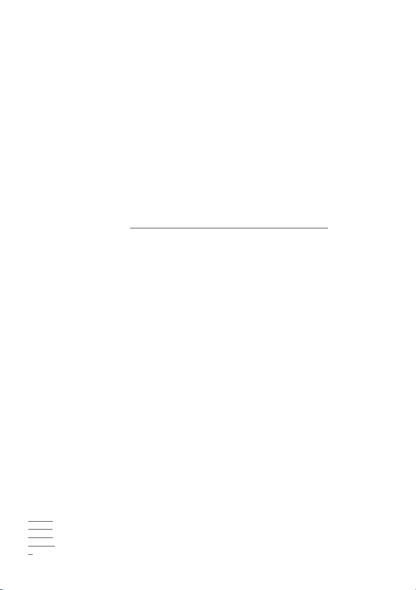
The hood may be in the filtering or the ducting version.
Filtering version (Fig. 1): The hood aspirates the kitchen air saturated with fumes and odours, purifies it through
the grease filters and charcoal filter and returns clean air into the room. For constant efficiency, the charcoal filter must
be replaced periodically. The charcoal filter is not supplied.
Ducting version (Fig. 2): The hood aspirates the kitchen air saturated with fumes and odours, passes it through the
grease filters and expels it to the outside through an outlet pipe. With this version the charcoal filter is not required. Decide
from the outset on the type of installation (filtering or ducting). For greater efficiency, we recommend you install the hood
in the ducting version (if possible).
INSTALLATION
ATTENTION: Two persons are required for proper installation; the unit should be installed by a qualified operator.
Remove the grease filters before proceeding with the assembly instructions. This will make the appliance easier to handle.
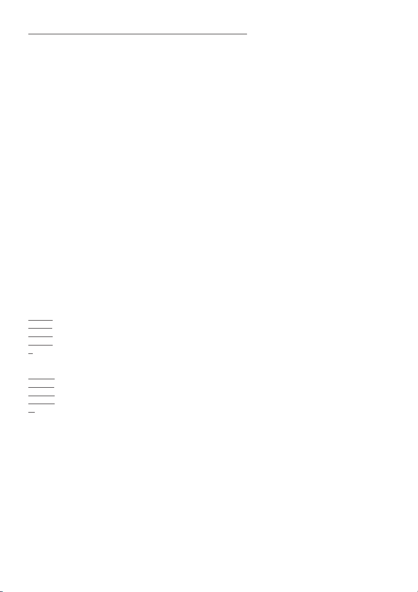
1. Removal of grease filters: Fig. 3: push the stop towards the rear of the appliance and turn the filter outwards.
INSTALLATION IN DUCTING VERSION: Before fixing, the outlet pipe for air evacuation to the outside must be installed.
Use an outlet pipe with: – minimum indispensable length; – minimum possible bends (maximum angle of bend: 90°); – certified
material (according to the State); – an as smooth as possible inside. It is also advisable to avoid any drastic changes
in pipe cross-section (recommended diameter: 150 mm). For air evacuation to the outside, follow all the other instructions
given on the “Warnings” sheet. Prepare the power supply within the telescopic chimney (for the electrical connection, follow
all the other instructions on the “Warnings” sheet).
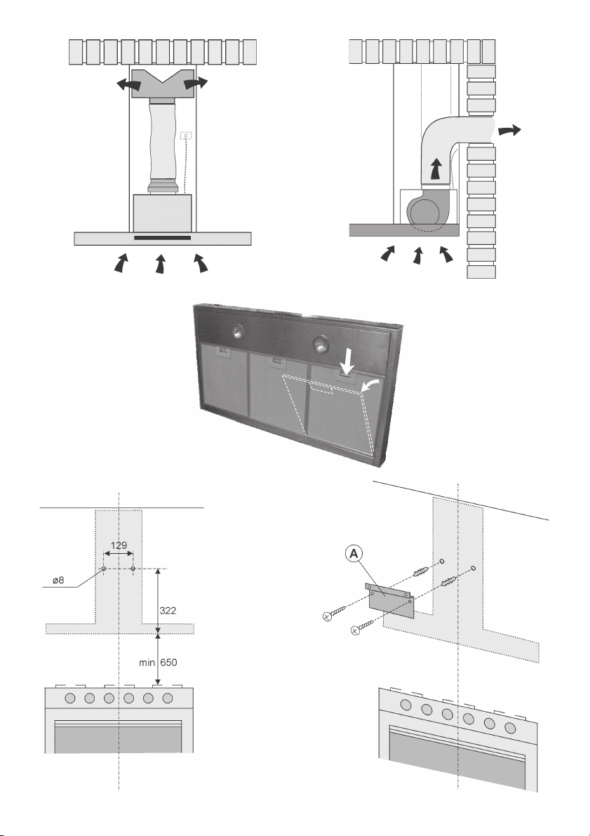
2. Fixing to the wall: Draw a line on the wall in vertical line with your hob. Mark the first 2 holes to be drilled in the
wall, respecting the distances indicated in Fig. 4. Drill the 2 holes and fit the screw anchors provided. As already specified
on the “Warnings” sheet, bear in mind that the distance between the lower edge of the hood and the hob must be min.
650 mm. Fix the metal bracket (A) to the wall using the 2 holes just drilled (Fig. 5); the screws for fixing the bracket are
provided. Use the 2 cut-out triangles on the bracket to position it exactly along the vertical axis of the hood. Hang the
hood on the bracket (Fig. 6). Adjust the horizontal position moving the hood to the right or left so that it is aligned with
the wall units. If you also need to adjust the hood in height, operate on the adjusting screws (B) provided.
Once adjusted, finally fix the hood with a further 4 screws (D): Mark the 4 holes to be drilled on the wall, unhook the
hood and drill the holes marked (8 mm diameter); then use the screw anchors and the screws provided for final fixing.
FOR CORRECT FUNCTIONING, THE HOOD MUST BE FIXED USING ALL FOUR SCREWS (D)!
3. Flange assembly: set the flange (E) over the motor and press slightly (Fig. 7).
4. Fixing the telescopic flues:
4a - Adjust the width of the support bracket (D) of the telescopic flue by means of the screws (E) as shown in Fig.8; then,
by means of the screw anchors and screws (F) provided, fix the bracket to the ceiling in such a way that it is positioned
along the axis with your hood.
4b - Connect the air outlet pipe to the air vent of the hood. - Use a flexible pipe and lock it to the air vent of the hood
with a metal hose clamp - Fig. 9 (pipe and clamp are not provided). - For exhaust hoods, turn the upper flue over so that
the air exhaust grid is in the lower section (Fig. 10).
4c - Plug in the hood. Insert the extension flues setting them on the hood; extend the upper flue to the ceiling and secure
with the 2 screws (H) - Fig. 11.
INSTALLATION IN FILTERING VERSION: Prepare the power supply within the telescopic flues (for the electrical
connection, follow all the other instructions on the “Warnings” sheet).
Fixing to the wall: for fixing to the wall refer to the instructions for the ducting version (see points 2 and 3), then
continue with the instructions below.
Fixing the telescopic flues: - Adjust the width of the support bracket (D) of the telescopic flue by means of the screws
(E) as shown in Fig. 8. - Then, by means of the screw anchors and screws (F) provided, fix the bracket to the ceiling in
such a way that it is positioned along the axis with your hood. - Mount the flange on the hood in correspondence to the
air outlet point (Fig. 12). – Take the air baffle and fit a flexible pipe to it (125 mm diameter) locking it with a metal hose
clamp (pipe and clamps are not provided). Fit the air baffle to the upper flue (Fig. 13) with 4 screws.
- Connect the flexible pipe to the flange on the air vent (Fig. 14). - Plug in the hood. Insert the extension flues setting
them on the hood; extend the upper flue to the ceiling and secure with the 2 screws H (Fig. 11). - Install the charcoal
filter fitting the two filter clips in their housings (Fig. 15) and turning the filter upward.
OPERATION
Depending on the model, the unit is equipped with the following controls:
Controls shown in Fig.16:
Button A: light button.
Button B: first speed motor ON/OFF button.
Page 3

Button C: second speed motor ON/OFF button.
Button D: third speed motor ON/OFF button.
E: motor on light.
Controls shown in Fig.17:
Button A: light button.
Button B: first speed motor ON/OFF button.
Button C: second speed button.
Button D: third speed button.
E: motor on light.
Pay special attention to the grease filters: the grease filters must be replaced periodically: exactly how often depends
on use (at least once every other month). To remove the filter: push inward on the clamp at the handle and pull the filter
downward. Wash out the filter using a neutral soap.
Replacing the charcoal filter: If the unit is a filtering hood, the charcoal filter must be replaced: to remove them press
inward on the clamp (Fig. 15) and rotate the filter downward until the 2 tabs can be removed from the housing. the charcoal
filters must be replaced according to use: on the average once every 6 months.
Lighting: Depending on the model purchased, see Fig.18 or Fig. 19.
Fig. 18: to change the halogen lamps open the cover levering from the proper slots. Replace with the same type of lamp.
Fig. 19: after having removed the grease filters, remove the light fitting, operating manually from inside the hood. Apply
light pressure to the mobile part of the 2 retainers and release it from the outside. Unscrew the bulb and replace it with
a bulb of the same type. Re-assemble the light fitting by pushing it into its seat from the outside.
DEUTSCH
BESCHREIBUNG
Die Haube steht in Umluftversion und in Abluftversion zur Verfügung.
Umluftversion (Abb. 1): Die Haube saugt die mit Rauch und Gerüchen gesättigte Luft an und reinigt sie durch die
Fett- und die Kohlefilter. Danach wird die saubere Luft wieder in den Raum geleitet. Um die gleichmäßige Wirksamkeit der
Kohlefilter zu erhalten, müssen sie regelmäßig ausgetauscht werden. Die Kohlefilter werden nicht mitgeliefert.
Abluftversion (Abb. 2): Die Haube saugt die mit Rauch und Gerüchen gesättigte Luft an, leitet sie durch die Fettfilter
und gibt sie über ein Abführungsrohr nach außen ab. Diese Version benötigt keinen Kohlefilter.
Entscheiden Sie sich von Anfang an für einen Installationstyp (Umluft oder Abluft). Um eine größere Wirkung zu erzielen,
empfehlen wir die Installation einer Haube in Abluftversion (falls möglich).
MONTAGE DES GERÄTS
ACHTUNG: Für die Montage sind wenigstens 2 Personen erforderlich. Es wird empfohlen, die Montage von Fachkräften
durchführen zu lassen. Vor Installation sind zur leichteren Handhabung des Geräts die Fettfilter zu entfernen.
1. Entfernung der Fettfilter: Abb. 3: den Festhalter in Richtung der Geräterückseite drücken und den Filter nach
außen drehen.
INSTALLATION DER ABLUFTVERSION: Vor der Befestigung muss das Rohr zur Abführung der Luft außen angebracht
werden. Ein Abführungsrohr verwenden, das folgende Eigenschaften besitzt: - erforderliche Mindestlänge; - so wenig
Kurven wie möglich (maximale Kurvenkrümmung: 90°); - zulässiges Material (Landesnormen); - Innenseite so glatt wie
möglich. Es wird außerdem empfohlen, starke Wechsel des Rohrdurchmessers zu vermeiden (empfohlener Durchmesser:
150 mm). Für die Luftabführung nach außen alle weiteren Angaben im Blatt “Hinweise” befolgen. Die Stromzufuhr innerhalb
des vom dekorativen Rohr benötigten Raums vorbereiten (für den elektrischen Anschluss alle weiteren im Blatt “Hinweise”
aufgeführten Angaben befolgen).
2. Befestigung an der Wand: Zeichnen Sie eine Linie auf die Wand, vertikal zu Ihrem Kochfeld. Markieren Sie die
ersten 2 anzubringenden Löcher auf der Wand, dabei sind die in Abb. 4 angegebenen Maße zu beachten. Die 2 Bohrungen
ausführen und die (mitgelieferten) Dübel einstecken. Wie bereits im Blatt “Hinweise” beschrieben, ist darauf zu achten,
dass der Abstand zwischen dem unteren Rand der Haube und der Kochfläche mindestens 650 mm betragen muss. Den
Metallbügel (A) an der Wand befestigen, dazu die gerade angebrachten 2 Löcher benutzen - Abb. 5 - (die Schrauben zur
Befestigung der Bügel sind mitgeliefert). Benutzen Sie die beiden auf dem Bügel ausgesparten Dreiecke, um diesen exakt
entlang der Längsachse der Haube zu positionieren.
Dann die Haube an dem Bügel einhaken (Abb. 6). Die horizontale Position regulieren, indem die Haube in Übereinstimmung
mit der Anordnung der Hängeschränke nach rechts oder nach links verschoben wird. Soll die Haube auch in der Höhe
reguliert werden, die mitgelieferten Regulierschrauben (B) entsprechend anwenden.
Nach erfolgter Ausrichtung ist die Haube endgültig mit den übrigen 4 Schrauben (D) zu befestigen: hierzu an der Wand
die 4 zu bohrenden Löcher markieren, Haube aushängen und die Löcher bohren (Durchmesser 8mm), wobei die beiden
mitgelieferten Dübel und Schrauben für die endgültige Befestigung zu verwenden sind.
Page 4

UM EINEN EINWANDFREIEN BETRIEB ZU GEWÄHRLEISTEN, MUSS DIE ABZUGSHAUBE MIT ALLEN VIER SCHRAUBEN
(D) BEFESTIGT WERDEN !
3. Montage des Flanschs: den Flansch (E) über dem Luftauslass des Motors positionieren und einen leichten Druck
ausüben (Abb. 7).
4. Befestigung der Teleskoprohre:
4a - Die Breite des Teleskoprohr-Tragbügels (D) über die in Abb. 8 gezeigten Schrauben (E) regulieren. Anschließend mit
Hilfe der mitgelieferten Dübel und Schrauben (F) den Bügel so an der Decke befestigen, dass er mit der Haube ausgerichtet
ist.
4b - Das Luftabführungsrohr an die Luftaustrittsöffnung der Haube anschließen; dazu einen Schlauch verwenden und ihn
an der Luftaustrittsöffnung der Haube mit einer Metallschelle befestigen - Abb. 9 - (Schlauch und Schelle werden nicht
mitgeliefert). Bei der Abluftversion ist das obere Rohr umzudrehen, damit sich die Luftaustrittsgitter unten befinden
(Abb.10).
4c - Über das Versorgungskabel die Stromversorgung der Haube herstellen. Die Teleskoprohre auf die Haube legen und
sie dann einfügen; das obere Rohr bis zur Decke führen und mit den 2 Schrauben (H) befestigen (Abb. 11).
INSTALLATION DER UMLUFTVERSION: Die Stromzufuhr innerhalb des vom dekorativen Rohr benötigten Raums vorbereiten
(für den elektrischen Anschluss alle weiteren im Blatt “Hinweise” aufgeführten Angaben befolgen).
Wandbefestigung: für die Wandbefestigung die Anleitung für die Abluftversion hinzuziehen (siehe Punkt 2 und 3), dann
gemäß der unten aufgeführten Anweisungen fortfahren.
Befestigung der Teleskoprohre: - Die Breite des Teleskoprohr-Tragbügels (D) über die in Abb. 8 gezeigten Schrauben
E regulieren. - Anschließend mit Hilfe der mitgelieferten Dübel und Schrauben (F) den Bügel so an der Decke befestigen,
dass er mit der Haube ausgerichtet ist. - Das Reduzierstück am Luftaustrittspunkt auf die Haube montieren (Abb. 12).
- Befestigen Sie einen Schlauch (Durchmesser 125 mm) an der Umluftweiche und sichern Sie ihn mit Hilfe einer Metallschelle
(Rohr und Schelle werden nicht mitgeliefert); befestigen Sie die Umluftweiche am oberen Rohr (Abb. 13) mit 4 Schrauben.
- Den Schlauch an das auf der Luftaustrittsöffnung befindliche Reduzierstück anschließen (Abb. 14). - Über das
Versorgungskabel die Stromversorgung der Haube herstellen. - Die Teleskoprohre auf die Haube legen und sie dann
einfügen; das obere Rohr bis zur Decke führen und mit 2 Schrauben H befestigen (Abb. 11). - Den Kohlefilter installieren,
dazu die beiden Laschen des Filters in den vorgesehenen Sitz (Abb. 15) einfügen und ihn nach oben drehen.
FUNKTIONSWEISE
Je nach Version ist das Gerät mit folgenden Bedienung ausgestattet:
Bedienung gemäß Abb.16:
A : Beleuchtung.
B : Motorschalter ON/OFF bei der I. Geschwindigkeit.
C : Motorschalter ON/OFF bei der II. Geschwindigkeit.
D : Motorschalter ON/OFF bei der III. Geschwindigkeit.
E : Motorkontrolleuchte.
Bedienung gemäß Abb.17:
A : Beleuchtung.
B : Ein- (erste Betriebstufe), Aus- Schalter.
C : zweite Betriebstufe.
D : dritte Betriebstufe.
E : Motorkontrolleuchte.
Mit besonderer Sorgfalt sind die Fettfilter zu behandeln: Der Fettfilter ist periodisch in Abhängigkeit vom Gebrauch
(mindestens jedoch alle zwei Monate) zu ersetzen. Entfernung des Filters: Den Festhalter in der Nähe des Griffs nach
innen drücken und den Filter nach unten ziehen. Die Filter mit einem neutralen Reiniger waschen.
Ersatz der Kohlefilter: Wird ein Gerät in Umluftversion eingesetzt, so müssen die Kohlefilter ersetzt werden: Den
Festhalter nach innen drücken (Abb. 15) und nach unten drehen, bis die beiden Filterzungen aus ihrem Sitz entfernt werden
können. Die Kohlefilter je nach Benutzung ersetzen; in der Regel alle 6 Monate.
Beleuchtung: Gemäß dem von Ihnen erworbenen Modell ist Abb. 18 oder Abb. 19 zu konsultieren.
Abb. 18: Um Halogenlampen zu ersetzen, den Deckel durch Einwirken auf den passenden Schlits öffnen. Mit Lampen
derselben Art ersetzen.
Abb. 19: nachdem die Fettfilter entfernt sind, den Deckel im Innern der Haube mit der Hand abheben. Das bewegliche Teil
der 2 Sperren mit leichtem Druck aus der Einfassung lösen. Die Glühlampe herausschrauben und durch eine Lampe
desselben Typs ersetzen. Den Deckel durch leichten Druck wieder auf seiner alten Position anbringen.
Page 5

FRANCAIS
DESCRIPTION
Cette hotte peut être en version recyclage ou en version évacuation.
Version Recyclage (Fig. 1): votre hotte aspire l’air de la cuisine imprégnée de fumée et d’odeurs, en l’épurant à travers
les filtres à graisse ainsi qu’à travers le filtre à charbon pour le renvoyer dans la pièce, propre. Afin que votre hotte soit
efficace d’une façon constante, il est nécessaire de remplacer le filtre à charbon périodiquement. Le filtre à charbon n’est
pas fourni.
Version évacuation (Fig. 2): votre hotte aspire l’air de la cuisine imprégnée de fumée et d’odeurs, en le faisant passer
à travers les filtres à graisse, puis en l’éliminant à l’extérieur à travers un tuyau d’évacuation. Dans cette version l’emploi
du filtre à charbon n’est pas nécessaire.
Vous devez décider dès le début quel type d’installation vous voulez (recyclage ou évacuation). Afin d’avoir une hotte
au rendement optimal, nous vous conseillons d’installer une hotte version évacuation (si cela est possible).
INSTALLATION
ATTENTION: Il faut au moins deux personnes pour monter cet appareil; il est conseillé de confier les opérations
d’installation à des spécialistes. Avant de procéder aux opérations de montage, pour manoeuvrer plus aisément l’appareil,
démontez les filtres à graisse.
1. Démontage des filtres à graisse: Fig. 3: pousser le blocage vers la partie arrière de l’appareil et tourner le filtre
vers l’extérieur.
INSTALLATION VERSION EVACUATION: Avant de commencer l’installation, il est nécessaire de prévoir le tuyau pour
l’évacuation de l’air à l’extérieur. Employez un tuyau d’évacuation qui ait: - la longueur minimale indispensable; - le moins
de coudes et raccords possibles (angle maximum des coudes: 90°); - qui soit fait d’une matière approuvée par les normes
en vigueur (suivant le pays); - sa surface intérieure la plus lisse possible. Nous vous conseillons aussi d’éviter les
changements brusques de section du tuyau (diamètre conseillé: 150 mm). Pour l’évacuation de l’air à l’extérieur, suivez
toutes les autres indications fournies par la feuille “Attention”. Prévoir l’alimentation électrique dans l’encombrement de
la cheminée télescopique (pour le branchement électrique, suivre toutes les autres indications se trouvant sur la feuille
“Attention”).
2. Fixation au mur: Tracez une ligne sur le mur, à la verticale de votre plan de cuisson. Tracez sur le mur les 2
premiers trous que vous devrez percer, en respectant les mesures indiquées à la Fig. 4; percez 2 trous et y placez les
4 chevilles (fournies en équipement). Comme indiqué sur la feuille “Attention”, ne pas oublier que la distance entre le bord
inférieur de la hotte et le plan de cuisson doit être au minimum de 650 mm. Fixez le support métallique (A) au mur en utilisant
les 2 trous percés - Fig. 5 - (les vis pour la fixation du support sont fournies).Utiliser les deux petits triangles découpés
sur le support afin de le placer exactement le long de l’axe vertical de la hotte.
Puis accrochez la hotte sur le support (Fig. 6). Régler la position horizontale en déplaçant la hotte à droite ou à gauche
selon les exigences de l’alignement avec les meubles suspendus. S’il faut aussi régler la hotte en hauteur, agir sur les
vis (B) de réglage (fournies).
Après le réglage,
la hotte et percer les trous marqués (diamètre 8mm) ; puis utiliser les chevilles et les vis fournies en équipement
pour la fixation définitive.
POUR UN FONCTIONNEMENT CORRECT, IL FAUT QUE LA HOTTE SOIT FIXEE PAR LES QUATRE VIS (D) !
3. Montage flange: positionner la flange (E) au-dessus de la bouche de sortie d’air du moteur et exercer une légère
pression (Fig. 7).
4. Fixation des tuyaux télescopiques:
4a - Régler la largeur de l’étrier de support (D) du tuyau télescopique à l’aide des vis (E) indiquées sur la Fig. 8; ensuite,
à l’aide des chevilles et des vis (F), fournies, fixer le support au plafond en faisant attention qu’il soit dans l’axe de la
hotte.
4b - Raccordez le conduit pour l’évacuation de l’air à la bouche de sortie d’air de la hotte; utilisez un tuyau souple et bloquezle sur la bouche de sortie d’air de la hotte à l’aide d’un collier métallique - Fig. 9 - (le tuyau et le collier ne sont pas fournis).
Pour la version aspirante retournez le tuyau supérieur de façon à ce que les grilles d’évacuation d’air soit dans la partie
du bas (Fig. 10).
4c - Effectuez le raccordement électrique de la hotte au moyen du câble d’alimentation. Installer les tuyaux télescopiques
en les appuyant sur la hotte ; soulever le tuyau supérieur jusqu’au plafond et le fixer à l’aide des 2 vis (H) – Fig. 11.
INSTALLATION VERSION RECYCLAGE: Prévoir l’alimentation électrique dans l’encombrement de la cheminée télescopique
(pour le branchement électrique, suivre toutes les autres indications se trouvant sur la feuille “Attention”).
Fixation au mur: pour la fixation au mur voir les instructions pour la version évacuation (voir point 2 et 3), puis continuer
avec les instructions indiquées ci-après.
Fixation des tuyaux télescopiques: - Régler la largeur de l’étrier de support (D) du tuyau télescopique à l’aide des
vis E indiquées à la Fig. 8. - Ensuite, à l’aide des chevilles et des vis (F) fournies, fixer le support au plafond en faisant
attention qu’il soit dans l’axe de la hotte. - Monter la réduction sur la hotte en face du point de sortie de l’air (Fig. 12).
fixer la hotte définitivement à l’aide des 4 vis (D) : marquer les 4 trous à percer sur le mur, décrocher
Page 6

- Prendre le déflecteur d’air et y fixer un tuyau souple (de 125 mm de diamètre) en le bloquant à l’aide d’un collier métallique
(le tuyau et le collier ne sont pas fournis); fixer le déflecteur d’air au tuyau supérieur (Fig. 13) à l’aide de 4 vis.
- Raccordez le tuyau souple à la réduction se trouvant sur la bouche de sortie d’air (Fig. 14). - Effectuez le raccordement
électrique de la hotte au moyen du câble d’alimentation. Installer les tuyaux télescopiques en les appuyant sur la hotte ;
soulever le tuyau supérieur jusqu’au plafond et le fixer à l’aide des 2 vis H (Fig. 11). - Installer le filtre à charbon en enfilant
les 2 languettes du filtre dans le logement prévu à cet effet (Fig. 15) et en le faisant tourner vers le haut.
FONCTIONNEMENT
Selon les modèles, l’appareil est muni des types suivants de commandes:
Commandes de la Fig.16:
Touche A: touche d’éclairage.
Touche B: touche ON/OFF moteur 1e vitesse.
Touche C: touche ON/OFF moteur 2e vitesse.
Touche D: touche ON/OFF moteur 3e vitesse.
E: voyant lumineux de fonctionnement du moteur.
Commandes de la Fig.17:
Touche A: touche d’éclairage.
Touche B: touche ON/OFF moteur 1e vitesse.
Touche C: touche 2e vitesse.
Touche D: touche 3e vitesse.
E: voyant lumineux de fonctionnement du moteur.
Prêter une attention particulière aux filtres à graisse:les filtres à graisse doit être remplacés périodiquement, en
fonction de l’utilisation (au moins tous les deux mois). Pour enlever le filtre: à l’aide de la poignée, pousser l’arrêt vers
l’intérieur et tirer le filtre vers le bas (Fig. 3). Laver les filtres avec une lessive neutre.
Remplacer le filtre à charbons: si l’on utilise l’appareil en version recyclage, il faut remplacer le filtre à charbons :
pour les sortir pousser le loquet de blocage vers l’intérieur (Fig. 15) et tourner le filtre vers le bas de manière à retirer les
2 languettes de leur logement. Vous devrez remplacer le filtre à charbon en fonction de l’utilisation, en moyenne tous les
6 mois.
Eclairage: en fonction du modèle acheté, consulter la Fig. 18 ou la Fig. 19.
Fig. 18: pour remplacez les lampes halogènes, ouvrez le couvercle en faisant levier grâce aux fissures prévues à cet
effet. Remplacez-les par des lampes ayant les mêmes caractéristiques.
Fig. 19: après avoir extrait les filtres à graisse, enlevez le plafonnier manuellement, en procédant par l’intérieur de la hotte.
Excercez une légère pression sur la partie mobile des deux arrêts, puis déboîter le plafonnier de l’extérieur. Dévissez
l’ampoule et la remplacez par une autre du même genre. Remontez le plafonnier en le poussant de l’extérieur dans son
logement.
ITALIANO
DESCRIZIONE
La cappa puo’ essere in versione filtrante o in versione aspirante.
Versione filtrante (Fig. 1): la cappa aspira l’aria della cucina impregnata di fumi e di odori, depurandola attraverso
i filtri anti-grasso ed il filtro carbone per poi re-immetterla pulita nella stanza. Per una costante efficienza, è necessario
sostituire periodicamente il filtro al carbone. Il filtro al carbone non è in dotazione.
Versione aspirante (Fig. 2): la cappa aspira l’aria della cucina impregnata di fumi e di odori facendola passare
attraverso i filtri anti-grasso, poi la espelle all’esterno attraverso un condotto di scarico. In questa versione non è necessario
utilizzare il filtro al carbone. Decidete sin dall’inizio il tipo di installazione (filtrante o aspirante). Per una maggiore efficienza,
consigliamo di installare la cappa in versione aspirante (se possibile).
INSTALLAZIONE
ATTENZIONE: per montare questo apparecchio sono necessarie almeno due persone; si consiglia comunque di affidare
le operazione di installazione a personale specializzato. Prima di procedere alle operazioni di montaggio, per una più
facile manovrabilità dell'apparecchio disinserire i filtri antigrasso.
1. Rimozione dei filtri antigrasso: Fig. 3: spingere il fermo verso la parte posteriore dell’apparecchio e ruotare
il filtro verso l’esterno.
INSTALLAZIONE IN VERSIONE ASPIRANTE: prima del fissaggio è necessario predisporre il condotto per lo scarico
dell’aria all’esterno. Utilizzare un condotto di scarico che abbia: – lunghezza minima indispensabile; – minor numero possibile
di curve (angolo massimo della curva:90°); – materiale approvato normativamente (a seconda dello Stato); – lato interno
Page 7

piú liscio possibile. Si consiglia inoltre di evitare cambiamenti drastici di sezione del tubo (diametro consigliato: 150 mm).
Per lo scarico dell’aria all’esterno, seguire tutte le altre indicazioni riportate nel foglio “Avvertenze”. Predisporre
l’alimentazione elettrica entro l’ingombro del tubo decorativo (per il collegamento elettrico, seguite tutte le altre indicazioni
riportate nel foglio “Avvertenze”).
2. Fissaggio a muro: Tracciate sulla parete una linea, sulla verticale del vostro piano di cottura. Segnate sulla
parete i primi 2 fori che dovrete fare, rispettando le misure indicate in Fig. 4; effettuate i 2 fori ed inserite i tasselli (in dotazione).
Come già specificato nel foglio "Avvertenze", tenere presente che la distanza tra il bordo inferiore della cappa ed il piano
cottura deve essere min 650 mm. Fissate la staffa metallica (A) alla parete utilizzando i 2 fori appena effettuati - Fig. 5
- (le viti per il fissaggio della staffa sono in dotazione). Utilizzare i 2 triangolini ritagliati sulla staffa per posizionarla
esattamente lungo l'asse verticale della cappa.
Agganciate quindi la cappa alla staffa (Fig. 6). Regolare la posizione orizzontale spostando la cappa a destra o a sinistra
secondo le esigenze di allineamento ai pensili. Se avete l'esigenza di regolare la cappa anche in altezza, operare sulle
apposite viti (B) di regolazione (in dotazione).
A regolazione avvenuta, fissare la cappa definitivamente con altre 4 viti (D): segnare sul muro i 4 fori da fare, sganciare
la cappa ed effettuare i fori segnati (diametro 8mm); utilizzare poi i tasselli e le viti in dotazione per il fissaggio
definitivo.
PER UN CORRETTO FUNZIONAMENTO, È NECESSARIO CHE LA CAPPA SIA FISSATA CON TUTTE E QUATTRO LE VITI
(D) !
3. Montaggio flangia: posizionare la flangia (E) sopra la bocca uscita aria del motore ed esercitare una leggera
pressione (Fig. 7).
4. Fissaggio dei tubi telescopici:
4a - Regolare la larghezza della staffa di supporto (D) del tubo telescopico tramite le viti (E) indicate in Fig. 8;
successivamente, mediante i tasselli e le viti (F) in dotazione, fissare la staffa al soffitto facendo in modo che sia in asse
con la vostra cappa.
4b - Collegare il condotto per lo scarico dell’aria con la bocca uscita aria della cappa; utilizzare un tubo flessibile e bloccarlo
alla bocca uscita aria della cappa con una fascetta metallica - Fig. 9 - (tubo e fascetta non sono in dotazione). Per la
versione aspirante capovolgere il tubo superiore in modo che le griglie di evacuazione aria siano nella parte bassa (Fig.10).
4c - Effettuare il collegamento elettrico della cappa mediante il cavo di alimentazione. - Inserire i tubi telescopici
appoggiandoli sulla cappa; sollevare il tubo superiore fino al soffitto e fissarlo tramite le 2 viti (H) - Fig. 11.
INSTALLAZIONE IN VERSIONE FILTRANTE: predisporre l’alimentazione elettrica entro l’ingombro del tubo decorativo
(per il collegamento elettrico, seguite tutte le altre indicazioni riportate nel foglio “Avvertenze”).
Fissaggio a muro: per il fissaggio a muro fare riferimento alle istruzioni per la versione aspirante (vedi punti 2 e 3),
poi proseguire con le istruzioni qui sotto riportate.
Fissaggio dei tubi telescopici: - Regolare la larghezza della staffa di supporto (D) del tubo telescopico tramite le
viti E indicate in Fig. 8. - Successivamente, mediante i tasselli e le viti (F) in dotazione, fissare la staffa al soffitto facendo
in modo che sia in asse con la vostra cappa. - Montare la riduzione sulla cappa, in corrispondenza del punto uscita aria
(Fig. 12).- Prendere il deflettore aria e fissateci un tubo flessibile (di diametro 125 mm) bloccandolo con una fascetta metallica
(tubo e fascette non sono in dotazione); fissare il deflettore aria al tubo superiore (Fig. 13) con 4 viti.
- Collegare il tubo flessibile alla riduzione presente sulla bocca uscita aria (Fig. 14). - Effettuare il collegamento elettrico
della cappa mediante il cavo di alimentazione. - Inserire i tubi telescopici appoggiandoli sulla cappa; sollevare il tubo
superiore fino al soffitto e fissarlo tramite le 2 viti H (Fig. 11). - Installare il filtro al carbone infilando le 2 linguette del
filtro nell'apposita sede (Fig. 16) e facendolo ruotare verso l'alto.
FUNZIONAMENTO
A seconda delle versioni l'apparecchio è dotato dei seguenti tipi di comandi:
Comandi di Fig. 16:
Tasto A: accende/spegne le luci.
Tasto B: tasto accensione ON/OFF motore alla I velocità.
Tasto C: tasto accensione ON/OFF motore alla II velocità.
Tasto D: tasto accensione ON/OFF motore alla III velocità.
E: spia di funzionamento del motore.
Comandi di Fig. 17:
Tasto A: accende/spegne le luci.
Tasto B: tasto accensione ON/OFF motore alla I velocità.
Tasto C: tasto II velocità.
Tasto D: tasto III velocità.
E: spia di funzionamento del motore.
Una cura particolare va rivolta ai filtri antigrasso: il filtro antigrasso deve essere sostituito periodicamente in rapporto
all'uso (almeno ogni due mesi). Per togliere il filtro: in corrispondenza della maniglia, spingere il fermo verso l'interno e
tirare il filtro verso il basso (Fig. 3). Lavate i filtri con detersivo neutro.
Page 8

Sostituzione filtro carbone: Nel caso d'uso dell'apparecchio in versione filtrante, sarà necessario sostituire il filtro
al carbone: per disinserirlo spingere il fermo verso l'interno (Fig. 15) e ruotare il filtro verso il basso fino a togliere le 2
linguette dalle loro sedi. Sostituire il filtro carbone in rapporto all'uso, mediamente ogni 6 mesi.
Illuminazione: A seconda del modello da voi acquistato, fare riferimento alla Fig.18 o Fig. 19.
Fig. 18: per sostituire le lampade alogene aprire il coperchio facendo leva sulle apposite fessure. Sostituire con lampade
dello stesso tipo.
Fig. 19: dopo aver tolto i filtri antigrasso, rimuovere la plafoniera operando manualmente dall’interno della cappa. Esercitare
una leggera pressione sulla parte mobile dei 2 fermi e sganciarla quindi dall’esterno. Svitare la lampada e sostituirla con
una lampada dello stesso tipo. Rimontare la plafoniera spingendola in sede dal lato esterno.
ESPAÑOL
DESCRIPCIÓN
La campana puede ser en versión filtrante o en versión aspirante.
Versión filtrante (Fig. 1): La campana aspira el aire de la cocina impregnado de humos y de olores depurándolo a
través de filtros antigrasa y filtro al carbón para luego introducirlo de nuevo limpio en la habitación. Para mayor eficacia,
es necesario sustituir periódicamente el filtro al carbón. El filtro de carbón no se suministra de serie.
Versión aspirante (Fig. 2): La campana aspira el aire de la cocina impregnado de humos y de olores haciéndolo pasar
a través de los filtros antigrasa, después lo expulsa hacia el exterior a través del conducto de descarga. En esta versión
no es necesario utilizar el filtro al carbón. Decida desde el principio el tipo de instalación (filtrante o aspirante). Para una
mayor eficacia, aconsejamos que se instale la campana en versión aspirante (si es posible).
INSTALACIÓN
CUIDADO: Para montar este aparato se necesitan al menos dos personas; le aconsejamos que lo haga instalar a
personal especializado. Antes de proceder a las operaciones de montaje, para que se pueda maniobrar el aparato con
mayor facilidad es necesario desconectar los filtros antigrasa.
1. Remoción de los filtros antigrasa: Fig. 3: Empujar el retén hacia la parte posterior del aparato y girar el filtro
hacia afuera.
INSTALACION EN VERSION ASPIRANTE: Antes de sujetar la campana es necesario colocar el conducto para la
descarga de aire al exterior. Utilice un conducto de descarga que tenga la longitud mínima indispensable, el menor número
posible de curvas (ángulo máximo de la curva = 90°), material de acuerdo con la normativa vigente (de cada país), parte
interna lo más lisa posible. Se aconseja además evitar cambios drásticos de sección del tubo (diámetro aconsejado: 150
mm). Para la descarga del aire hacia el exterior, siga todas las demás indicaciones que aparecen en la página “Advertencias”.
Preparar los cables de alimentación eléctrica dentro de las dimensiones del tubo decorativo (para la conexión eléctrica,
seguir las restantes indicaciones de la página “Advertencias”).
2. Fijación a la pared: Trazar sobre la pared una línea vertical respecto del plano de cocción. Marcar sobre la pared
los primeros dos orificios necesarios, respetando las medidas indicadas en la Fig. 4, realizar los dos orificios e introducir
las espigas incluidas en el equipamiento. Como ya especificado en la página “Advertencias”, tener en cuenta que la distancia
entre el borde inferior de la campana y el plano de cocción debe ser de al menos 650 mm. Fijar el estribo metálico (A)
a la pared utilizando los dos orificios realizados anteriormente - Fig. 5 - (los tornillos para la fijación del estribo están incluidos
en el equipamiento). Servirse de los dos triángulos recortados en el estribo para emplazarlo correctamente a lo largo del
eje vertical de la campana. Luego enganchar la campana al estribo (Fig. 6). Regular la posición horizontal desplazando
la campana hacia la derecha o la izquierda, siguiendo la alineación con los muebles de pared. Si fuera necesario regular
también la altura de la campana, servirse de los tornillos de regulación correspondientes (B) incluidos en el equipamiento.
Al terminar la regulación,
a realizar, desenganche la campana y efectúe los agujeros marcados (diámetro 8mm); luego, utilice los tacos y los
tornillos suministrados para la fijación definitiva.
PARA QUE EL FUNCIONAMIENTO SEA CORRECTO, ¡ES NECESARIO FIJAR LA CAMPANA UTILIZANDO TODOS LOS
TORNILLOS (D) PREVISTOS (CUATRO)!
3. Colocación de la brida: colocar la brida (E) sobre la boca de la salida del aire del motor y realizar una ligera
presión (Fig. 7).
4. Fijación de los tubos telescópicos:
4a - Regular el ancho del estribo de soporte (D) del tubo telescópico mediante los tornillos (E) indicados en la Fig.8;
posteriormente, mediante las espigas y los tornillos (F) incluidos en el equipamiento, fijar el estribo al techo de manera
que sea alineado con la campana.
4b - Conectar el conducto de evacuación del aire con la salida del aire de la campana. Utilizar un tubo flexible, trabándolo
en la boca de salida del aire de la campana mediante una abrazadera metálica - Fig. 9 - (el tubo y la abrazadera no están
incluidos en el equipamiento). Para la versión aspirante hay que invertir el tubo superior de manera que las rejillas de salida
del aire queden en la parte inferior (Fig. 10).
4c - Efectuar la conexión eléctrica de la campana extractora mediante el cable de alimentación. Introducir los tubos
fije la campana definitivamente con otros 4 tornillos (D): marque en la pared los 4 agujeros
Page 9

telescópicos apoyándolos sobre la campana extractora; levantar el tubo superior hasta el techo y asegurarlo con 2 tornillos
(H) - Fig. 11.
INSTALACION DE LA VERSION FILTRANTE: Preparar los cables de alimentación eléctrica dentro de las dimensiones
del tubo decorativo (para la conexión eléctrica, seguir las restantes indicaciones de la página “Advertencias”).
Fijación a la pared: Para la fijación a la pared tomar como referencia las instrucciones para la versión aspirante (véase
punto 2, 3), luego proseguir con las siguientes instrucciones.
Fijación de los tubos telescópicos: - Regular el ancho del estribo de soporte (D) del tubo telescópico mediante los
tornillos (E) indicados en la Fig. 8. - Posteriormente, mediante las espigas y los tornillos (F) incluidos en el equipamiento,
fijar el estribo al techo de manera que sea alineado con la campana. - Montar el adaptador en la boca de salida del aire
de la campana (Fig. 12). – Tomar el deflector de aire y fijar al mismo un tubo flexible de 125 mm de diámetro, asegurándolo
mediante una abrazadera metálica (ninguno de estos elementos se entrega con el equipamiento); fijar el deflector de aire
al tubo superior (Fig. 13) mediante 4 tornillos.
- Conectar el tubo flexible a la reducción presente en la boca de salida del aire (Fig. 14). - Efectuar la conexión eléctrica
de la campana extractora mediante el cable de alimentación. Introducir los tubos telescópicos apoyándolos sobre la
campana extractora; levantar el tubo superior hasta el techo y asegurarlo con 2 tornillos H (Fig. 11). - Instalar el filtro
de carbón introduciendo las dos lengüetas del mismo en el alojamiento correspondiente (Fig. 15) y haciéndolo girar hacia
arriba.
FUNCIONAMIENTO
Según la versión, el aparato está dotado de los siguientes tipos de mandos:
Mandos de la Fig.16:
Botón A: botón encendido luz.
Botón B: botón encendido ON/OFF motor en la Ia velocidad.
Botón C: botón encendido ON/OFF motor en la II velocidad.
Botón D: botón encendido ON/OFF motor en la III velocidad.
E: piloto luminoso de funcionamiento del motor.
Mandos de la Fig.17:
Botón A: botón encendido luz.
Botón B: botón encendido ON/OFF motor en la Ia velocidad.
Botón C: botón II velocidad.
Botón D: botón III velocidad.
E: piloto luminoso de funcionamiento del motor.
Los filtros antigrasa requieren un cuidado particular: los filtros antigrasa deben ser cambiados periódicamente con
relación al uso (por lo menos cada dos meses). Para quitar el filtro: a nivel de la manilla, empujen el retén hacia el interior
y tiren el filtro hacia abajo (Fig. 3). Laven los filtros con detergente neutro.
Cambio del filtro de carbón: Cuando se usa el aparato con la versión filtrante, hay que cambiar el filtro de carbón:
para sacarlos empujen el retén hacia dentro (Fig. 15) y giren hacia abajo el filtro hasta que las dos lengüetas salgan de
sus alojamientos. Cambiar los filtros de carbón con relación al uso, más o menos cada 6 meses.
Iluminación: En base al modelo que tengan ustedes, tomen como referencia la Fig.18 o la Fig.19.
Fig. 18: para cambiar las lámparas halógenas,abra la tapa haciendo palanca sobre las hendiduras apropiadas .Cambien
con lámparas del mismo tipo.
Fig.19: luego de haber quitado los filtros antigrasa, extraiga manualmente el aplique para techo desde el interior de la
campana. Ejerza una leve presión sobre la parte móvil de los 2 retenes y desengánchela luego desde el exterior.
Desenrosque la lámpara y sustitúyala con una lámpara del mismo tipo. Vuelva a montar el aplique para techo, empujando
el lado exterior del mismo hasta que se encastre en su asiento.
PORTUGUÊS
DESCRIÇÃO
O aparelho pode ser instalado na versão filtrante ou na versão aspirante.
Versão filtrante (Fig. 1): o exaustor aspira o ar impregnado de fumos e cheiros da cozinha, depurando-o através
os filtros antigordura e o filtro de carvão, e depois reintroduz o ar purificado no ambiente. Para que a sua eficiência
seja constante, é necessário substituir os filtros de carvão periodicamente. O filtro de carvão não é fornecido de série.
Versão aspirante (Fig. 2): o exaustor aspira o ar impregnado de fumos e cheiros da cozinha, fazendo-o passar através
dos filtros anti-gordura, e depois expele-o para o exterior através de uma conduta de descarga. Nesta versão não é
necessário utilizar o filtro de carvão. Decidir, inicialmente, o tipo de instalação desejada (filtrante ou aspirante). Para maior
eficiência, aconselhamos que o exaustor seja instalado na versão aspirante (se possível).
Page 10
INSTALAÇÃO
ATENÇÃO: para montar este aparelho são necessárias pelo menos duas pessoas; sugerimos a utilização de
pessoal especializado para realizar as operações de instalação. Antes de proceder às operações de montagem, é
conveniente desmontar os filtros anti-gordura para poder manipular mais facilmente o aparelho.
1. Remoção dos filtros anti-gordura: Fig. 3: empurrar o retentor em direcção à traseira do aparelho e rodar o filtro
para o exterior.
INSTALAÇÃO NA VERSÃO ASPIRANTE: Antes da fixação é necessário preparar a conduta para evacuação de ar,
no exterior. Utilizar uma conduta de descarga que tenha: - o comprimento mínimo indispensável; - o menor número de
curvas possível (ângulo máximo da curva:90°); - material aprovado pelos regulamentos de lei existentes (de acordo com
o Estado); - o lado de dentro o mais liso possível. Aconselha-se ainda evitar mudanças drásticas de secção de tubo
(diâmetro aconselhado: 150 mm). Para a evacuação de ar para o exterior, seguir todas as indicações dadas na folha
“Advertências”. Preparar a alimentação eléctrica dentro dos limites do espaço ocupado pelo tubo decorativo (para a ligação
eléctrica, seguir as indicações dadas na folha “Advertências”).
2. Fixação na parede: Traçar uma linha na parede, sobre a vertical da placa do seu fogão. Marcar na parede os
2 primeiros furos a fazer, respeitando as medidas indicadas na Fig. 4; fazer os 2 furos e introduzir as buchas (fornecidas
com o aparelho). Conforme já referimos na folha das “Advertências”, é necessário ter presente que a distância entre a
borda inferior do exaustor e a placa do fogão deve ser igual ou superior a 650 mm. Fixar o suporte metálico (A) na parede,
utilizando os 2 furos acabados de fazer - Fig. 5 - (os parafusos para fixar o referido suporte são fornecidos com o aparelho).
Utilizar os 2 triângulos recortados no suporte para o colocar exactamente ao longo do eixo vertical do exaustor. Prender
então o exaustor ao suporte (Fig. 6). Regular a horizontalidade do exaustor de acordo com o alinhamento dos armários
de cozinha, deslocando-o para a direita ou para a esquerda. Se houver necessidade de regular também a altura do exaustor,
mexer nos parafusos de regulação específicos (B) (fornecidos com o aparelho).
Uma vez efectuada a regulação, fixar definitivamente o exaustor com os outros 4 parafusos (D): marcar na parede
os 4 furos a fazer, desprender o exaustor e efectuar os furos marcados (diâmetro 8mm); utilizar os parafusos com
buchas e os parafusos fornecidos para fixar definitivamente.
PARA UM FUNCIONAMENTO CORRECTO, É NECESSÁRIO QUE O EXAUSTOR ESTEJA FIXADO COM TODOS OS
QUATRO PARAFUSOS (D) !
3. Montagem flange: coloque a flange (E) por cima da boca da saída do ar do motor e exerça uma ligeira pressão
(Fig. 7).
4. Fixação dos tubos telescópicos:
4a - Regular a largura da armação de suporte (D) do tubo telescópico com os parafusos (E) indicados na Fig. 8; fixar depois
o suporte no tecto com as buchas e parafusos (F) fornecidos, sobre o eixo de simetria vertical do exaustor.
4b - Ligar a conduta para evacuação do ar à boca de saída de ar do exaustor; utilizar um tubo flexível e fixá-lo à boca
de saída de ar com uma braçadeira metálica - Fig. 9 - (o tubo e a braçadeira não são fornecidos com aparelho). Para
a versão aspirante, inverter o tubo superior de maneira a fazer com que as grelhas de evacuação de ar fiquem para baixo
(Fig. 10).
4c - Fazer a ligação eléctrica do exaustor ligando o cabo de alimentação. Inserir os tubos telescópicos apoiando-os por
cima do exaustor; levantar o tubo superior até ao tecto e fixá-lo com os 2 parafusos (H) - Fig. 11.
INSTALAÇÃO NA VERSÃO FILTRANTE: Preparar a alimentação eléctrica dentro dos limites do espaço ocupado pelo
tubo decorativo (para a ligação eléctrica, seguir as indicações dadas na folha “Advertências”).
Fixação à parede: para a fixação à parede, começar por seguir as instruções dadas para a versão aspirante (ver
pontos 2, 3) e depois prosseguir de acordo com as instruções que damos abaixo.
Fixação dos tubos telescópicos: - Regular a largura da armação de suporte (D) do tubo telescópico nos parafusos
E, indicados na Fig. 8. - Fixar depois o suporte no tecto com as buchas e parafusos (F) fornecidos, colocando-o sobre
o eixo de simetria vertical do exaustor. - Montar a redução por cima do exaustor, na posição correspondente ao ponto
de saída de ar (Fig. 12). - Agarrar no deflector de ar e fixar nele um tubo flexível (com 125 mm de diâmetro), imobilizandoo com uma braçadeira metálica (o tubo e as braçadeiras não são fornecidos com o exaustor); fixar o deflector de ar ao
tubo superior (Fig. 13) com 4 parafusos.
- Ligar o tubo flexível à redução existente na boca de saída de ar (Fig. 14). - Fazer a ligação eléctrica do exaustor ligando
o cabo de alimentação. - Inserir os tubos telescópicos apoiando-os por cima do exaustor; levantar o tubo superior até
ao tecto e fixá-lo com os 2 parafusos H (Fig. 11). - Montar o filtro de carvão introduzindo as 2 linguetas do filtro na respectiva
sede (Fig. 15) e rodando-o para cima.
FUNCIONAMENTO
Os comandos variam de acordo com a versão do aparelho. Os tipos de comandos existentes são os seguintes:
Comandos da Fig.16:
Botão A: botão da luz.
Botão B: botão de ligação ON/OFF motor na I velocidade.
Botão C: botão de ligação ON/OFF motor na II velocidade.
Botão D: botão de ligação ON/OFF motor na III velocidade.
E: lâmpada piloto de funcionamento do motor.
Page 11

Comandos da Fig.17:
Botão A: botão de acendimento da luz.
Botão B: botão de acendimento ON/OFF motor na I velocidade.
Botão C: botão II velocidade.
Botão D: botão III velocidade.
E: lâmpada piloto de funcionamento do motor.
Os filtros anti-gordura necessitam de alguns cuidados especiais: o filtro anti-gordura deve ser substituído
periodicamente, em função da frequência de utilização (pelo menos de dois em dois meses). Para tirar o filtro: na posição
correspondente ao puxador, empurrar a tranqueta para dentro e puxar o filtro para baixo (Fig. 3). Lavar os filtros utilizando
um detergente neutro.
Substituição dos filtros de carvão: No caso de se usar o aparelho na versão filtrante, vai ser necessário substituir
o filtro de carvão: para os tirar empurrar a tranqueta para dentro (Fig. 15) e rodar o filtro para baixo até tirar as 2 linguetas
das sedes respectivas. Proceder à substituição dos filtros em função da utilização do exaustor e sempre, em média,
de 6 em 6 meses.
Iluminação: Considerar a Fig. 18 ou 19, consoante o modelo adquirido.
Fig. 18: para cambiar las lámparas halógenas, abrir a tampa fazendo alavanca nas fendas apropriadas. Substituir por
lámparas do mesmo tipo.
Fig. 19: depois de ter retirado os filtros anti-gordura, remover a armadura de luz protegida agindo manualmente por dentro
do exaustor. Exercitar uma pressão leve na parte móvel dos 2 stops e desenganchá-la puxando para fora. Desatarraxar
a lâmpada e substitui-la com uma lâmpada do mesmo tipo. Montar novamente a armadura de luz protegida empurrandoa pelo lado externo para colocá-la no seu assento.
NEDERLANDS
BESCHRIJVING
De wasemkap kan worden gebruikt in de filter- of afzuigversie.
Filterversie (Afb. 1): de afzuigkap zuigt de met verbrandingsgassen en onaangename luchtjes doordrongen kooklucht
af en zuivert de lucht via de vetfilters en het koolstoffilter waarna de schone lucht weer in de ruimte geblazen wordt. Om
ervoor te zorgen dat de werking voortdurend doeltreffend is moeten het koolstoffilters regelmatig vervangen worden. De
koolstoffilter is niet bijgeleverd.
Afzuigversie (afb. 2): de afzuigkap zuigt de met verbrandingsgassen en onaangename luchtjes doordrongen
kooklucht af en zorgt ervoor dat de lucht door de vetfilters gaat en vervolgens via een afvoerpijp rechtstreeks naar buiten
geleid wordt. Bij deze versie is de toepassing van koolstoffilters niet nodig. Bepaal vanaf het begin het type installatie
(filter- of afzuigversie). Voor een grotere doeltreffendheid adviseren wij u om (indien mogelijk) de afzuigkap in de afzuigversie
te installeren.
INSTALLATIE
LET OP: Dit apparaat moet door minstens twee personen gemonteerd worden. De installatie kan het beste overgelaten
worden aan vakmensen. Voor de montage de vetfilters verwijderen. Zo wordt het werk vergemakkelijkt.
1. Verwijdering van de vetfilters: Afb. 3: duw de vergrendeling naar de achterkant van het apparaat en draai het
filter naar buiten.
INSTALLATIE IN DE AFZUIGVERSIE: alvorens de afzuigkap te bevestigen moet u eerst de pijp voor de luchtafvoer
naar buiten in orde maken. Gebruik een afvoerpijp die de volgende eigenschappen heeft: - minimum benodigde lengte;
- zo min mogelijk bochten (maximaal toegestane hoek van de bochten: 90°); - materiaal dat goedgekeurd is volgens de
voorschriften (afhankelijk van het land); - binnenkant zo glad mogelijk. Er wordt bovendien geadviseerd om drastische
veranderingen van de doorsnede van de pijp te vermijden (geadviseerde diameter: 150 mm). Om de lucht naar buiten af
te voeren moet u alle andere aanwijzingen die op het blad “Opgelet” staan opvolgen. Bereid de elektrische voeding voor
binnen het ruimtebeslag van de sierpijp (volg voor de elektrische aansluiting alle andere aanwijzingen op die vermeld worden
in het hoofdstuk “Opgelet”).
2. Bevestiging aan de muur: teken op de verticale aslijn van uw kookplaat een lijn op de muur af. Teken de 2 gaten
die geboord moeten worden op de muur af en houd daarbij de maten aan die op afb. 4 staan; boor de 2 gaten en steek
er de (meegeleverde) pluggen in. Zoals reeds vermeld in het hoofdstuk “Waarschuwingen” moet u er rekening mee houden
dat de afstand tussen de onderste rand van de afzuigkap en de kookplaat minimaal 650 mm moet bedragen. Bevestig
de metalen beugel (A) aan de muur in de 2 zojuist geboorde gaten - afb.5 - (de schroeven voor bevestiging van de beugel
zijn bijgeleverd). Gebruik de beide driehoekjes die uitgesneden zijn in de beugel om de beugel exact langs de verticale
aslijn van de afzuigkap te plaatsen.
Haak de afzuigkap daarna aan de beugel (Afb. 6). Stel de horizontale positie af door de afzuigkap naar rechts of naar
links te verplaatsen zodat de afzuigkap precies op één lijn met de keukenkasten komt te zitten. Mocht het noodzakelijk
zijn om de afzuigkap ook in de hoogte af te stellen, dan moet u aan de speciale stelschroeven (B) draaien (meegeleverd).
Page 12
Bevestig na afstelling de kap definitief met nog 4 andere schroeven (D): teken op de muur de 4 te boren gaten af, haak
de kap los en boor de 4 afgetekende gaten (diameter 8 mm); gebruik vervolgens de bijgeleverde pluggen en schroeven
voor de definitieve bevestiging.
VOOR EEN CORRECTE WERKING, MOET DE AFZUIGKAP BEVESTIGD WORDEN MET DE VIER SCHROEVEN (D)!
3. Montage kraag: plaats de kraag (E) boven de luchtuitlaatopening van de motor en oefen een lichte druk uit (Afb.7).
4. Bevestiging van de telescopische pijp:
4a - Stel de breedte van de steunbeugel (D) van de telescopische pijp in met de schroeven (E) van afb. 8; Zet vervolgens
de beugel vast aan het plafond, met de bijgeleverde pluggen en schroeven (F), zodat hij recht is ten opzichte van de kap.
4b - Verbind de luchtafvoerpijp met de luchtafvoeropening van de kap; gebruik een buigzame slang en zet deze aan de
luchtuitgang van de afzuigkap vast met een metalen bandje - afb. 9 - (slang en bandje worden niet bijgeleverd). Bij de
afzuigversie moet de bovenste pijp ondersteboven geplaatst worden zodat de luchtafvoerroosters aan de onderkant komen
te zitten (Afb. 10).
4c - Breng de elektrische aansluiting van de afzuigkap door middel van de voedingskabel tot stand. Doe de telescopische
pijpen erin en laat ze op de afzuigkap steunen; doe de bovenste pijp tot aan het plafond omhoog en maak hem met de
beide schroeven (H) – Afb. 11 vast.
INSTALLATIE IN DE FILTERVERSIE: Bereid de elektrische voeding voor binnen het ruimtebeslag van de sierpijp (volg
voor de elektrische aansluiting alle andere aanwijzingen op die vermeld worden in het hoofdstuk “Waarschuwingen”).
Bevestiging aan de muur: zie de aanwijzingen voor de afzuigversie om de kap aan de muur te bevestigen (zie punt
2, 3), en ga vervolgens verder met onderstaande aanwijzingen.
Bevestiging van de telescopische pijpen: - regel de breedte van de steunbeugel (D) van de telescopische pijp door
middel van de schroeven E, aangegeven op afb. 8. - Zet vervolgens de beugel vast aan het plafond, met de bijgeleverde
pluggen en schroeven (F), zodat hij recht is ten opzichte van de kap. - Monteer het verloopstuk ter hoogte van het
luchtuitlaatpunt op de afzuigkap (afb. 12). – Neem het afbuigrooster en zet er een buigzame slang op vast (diameter 125
mm), en blokkeer hem met een metalen bandje (slang en bandjes worden niet bijgeleverd); bevestig het afbuigrooster aan
de bovenste slang (afb. 13) met 4 schroeven.
- Verbind de slang met de reductie op de luchtuitgangsopening (Afb. 14). - Breng de elektrische aansluiting van de afzuigkap
tot stand met de voedingskabel. Steek de telescopische pijpen erin en laat ze op de afzuigkap steunen; schuif de bovenste
pijp tot aan het plafond omhoog en maak hem met de beide schroeven (H) Afb.11 vast. - Installeer de koolstoffilter door
de 2 lipjes van de filter in de daarvoor bestemde behuizing te steken (Afb. 15) en draai hem naar boven.
WERKING
Afhankelijk van de versies is het apparaat uitgerust met de volgende bedieningselementen:
Bedieningselementen van Afb.16:
Toets A: lichtschakelaar.
Toets B: aan/uitschakelaar van de motor: eerste snelheid.
Toets C: aan/uitschakelaar van de motor: 2de snelheid.
Toets D: aan/uitschakelaar van de motor: 3de snelheid.
E: controlelampje dat aangeeft dat de motor in werking is.
Bedieningselementen van Afb.17:
Toets A: lichtschakelaar.
Toets B: aan/uitschakelaar van de motor: eerste snelheid.
Toets C: 2de snelheidsschakelaar.
Toets D: 3de snelheidsschakelaar.
E: controlelampje dat aangeeft dat de motor in werking is.
Er dient met name zorg besteed te worden aan de vetfilters: het vetfilter moet van tijd tot tijd vervangen worden in
verhouding tot de mate waarin het apparaat gebruikt wordt (minimaal één keer in de twee maanden). Om het filter te
verwijderen: druk ter hoogte van de handgreep de pal naar binnen en trek het filter naar beneden (Afb. 3). Reinig de filters
met een neutraal afwasmiddel.
Vervanging van de koolstoffilters: Indien u het apparaat in de filterversie gebruikt moeten de koolstoffilters vervangen
worden: om de filters te verwijderen moet u de pal naar binnen duwen (Afb. 15) en het filter naar beneden draaien totdat
de beide lipjes van hun plaats komen. Dan moet u de koolstoffilter vervangen in verhouding tot de mate waarin het apparaat
gebruikt wordt, gemiddeld één keer in de 6 maanden.
Verlichting: Afhankelijk van het door u aangeschafte model moet u zich aan Afb. 18 of Afb. 19 houden.
Afb. 18: voor vervanging van de halogeenlampjes de deksel openen door het op te lichten in de daarvoor bestemde opening.
Vervangen met lampen van hetzelfde type.
Afb. 19: nadat de vetfilters zijn verwijderd, de deksel binnen de kap met de hand verwijderen. Het mobiele gedeelte van
de 2 stoppen met lichte druk uit het raam drukken. De gloeilamp eruit draaien en door een lamp van hetzelfde type vervangen.
De deksel door lichte druk weer op zijn gelone positive terug brengen.
Page 13
12
3
4
5
Page 14

6
8
7
9
Page 15

10
12
11
13
14
Page 16

15
18
16
17
19
04307626/1S - K181s.n.
 Loading...