

Page 1
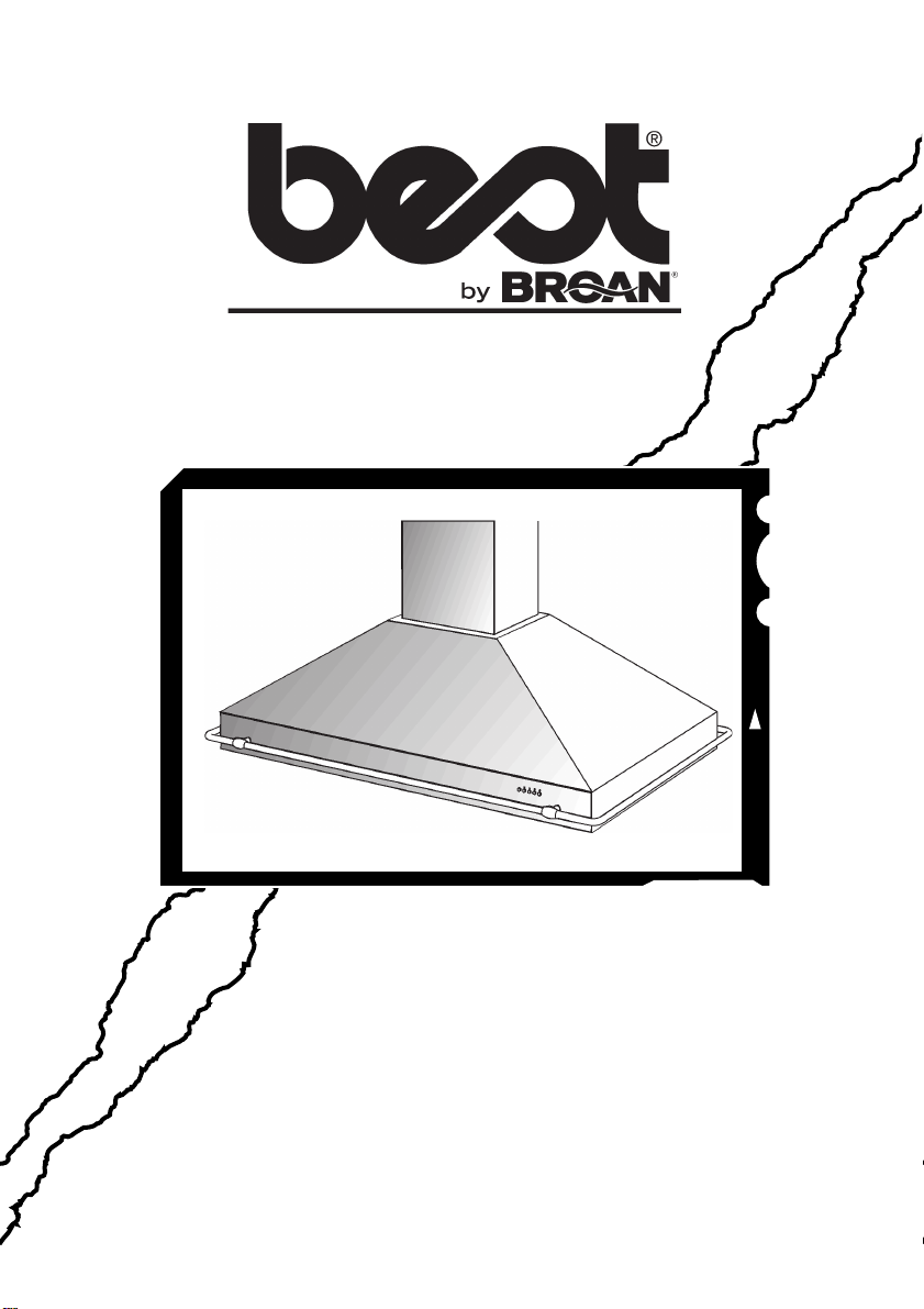
Model ISER222
ENGLISH.........................................2
FRANÇAIS.................................... 11
ESPAÑOL......................................20
BEST BY BROAN P.O. Box 140 Hartford, WI 53027
Page 2
READ AND SAVE THESE INSTRUCTIONS
!
INTENDED FOR DOMESTIC COOKING ONLY
!
WARNING
TO REDUCE THE RISK OF FIRE, ELECTRIC SHOCK, OR INJURY TO PERSONS,
OBSERVE THE FOLLOWING:
1. Use this unit only in the manner intended by the manufacturer. If you have questions,
contact the manufacturer at the address or telephone number listed in the warranty.
2. Before servicing or cleaning unit, switch power off at service panel and lock service
panel to prevent power from being switched on accidentally. When the service
disconnecting means cannot be locked, securely fasten a prominent warning device,
such as a tag, to the service panel.
3. Installation work and electrical wiring must be done by a qualified person(s) in accordance with all applicable codes and standards, including fire-rated construction codes
and standards.
4. Sufficient air is needed for proper combustion and exhausting of gases through the flue
(chimney) of fuel burning equipment to prevent backdrafting. Follow the heating equipment manufacturer’s guidelines and safety standards such as those published by the
National Fire Protection Association (NFPA), and the American Society for Heating,
Refrigeration and Air Conditioning Engineers (ASHRAE), and the local code authorities.
5. When cutting or drilling into wall or ceiling, do not damage electrical wiring and other
hidden utilities.
6. Ducted fans must always be vented to the outdoors.
7. Do not use this unit with any separate solid-state speed control device.
8. To reduce the risk of fire, use only metal ductwork.
9. This unit must be grounded.
TO REDUCE THE RISK OF A RANGE TOP GREASE FIRE:
A. Never leave surface units unattended at high settings. Boilovers cause smoking and
greasy spillovers that may ignite. Heat oils slowly on low or medium settings.
B. Always turn hood ON when cooking at high heat or when flambeing food (i.e. Crepes
Suzette, Cherries Jubilee, Peppercorn Beef Flambe’).
C. Clean ventilating fans frequently. Grease should not be allowed to accumulate on fan or
filter.
D. Use proper pan size. Always use cookware appropriate for the size of the surface
element.
WARNING
TO REDUCE THE RISK OF INJURY TO PERSONS IN THE EVENT OF A RANGE TOP
GREASE FIRE, OBSERVE THE FOLLOWING:*
1. SMOTHER FLAMES with a close-fitting lid, cookie sheet, or metal tray, then turn off the
burner. BE CAREFUL TO PREVENT BURNS. If the flames do not go out immediately,
EVACUATE AND CALL THE FIRE DEPARTMENT.
2. NEVER PICK UP A FLAMING PAN - You may be burned.
3. DO NOT USE WATER, including wet dishcloths or towels - violent steam explosion will
result.
4. Use an extinguisher ONLY if:
A. You know you have a Class ABC extinguisher and you already know how to operate
it.
B. The fire is small and contained in the area where it started.
C. The fire department is being called.
D. You can fight the fire with your back to an exit.
* Based on “Kitchen Fire Safety Tips” published by NFPA.
- 2 -
Page 3

!
CAUTION
1. To reduce risk of fire and to properly exhaust air, be sure to duct air outside. Do not vent
exhaust air into spaces within walls or ceilings or into attics, crawl spaces, or garages.
2. Take care when using cleaning agents or detergents.
3. Avoid using food products that produce flames under the Range Hood.
4. For general ventilating use only. Do not use to exhaust hazardous or explosive materials and vapors.
5. To avoid motor bearing damage and noisy and/or unbalanced impellers, keep drywall
spray, construction dust, etc. off power unit.
6. Your hood motor has a thermal overload which will automatically shut off the motor if it
becomes overheated. The motor will restart when it cools down. If the motor continues
to shut off and restart, have the hood serviced.
7. For best capture of cooking impurities, the bottom of the hood should be a minimum of
24" and a maximum of 30" above the cooking surface.
8. 3 installers are recommended because of the large size and weight of this hood.
9. This product is equipped with a thermostat which may start blower automatically. To
reduce the risk of injury and to prevent power from being switched on accidentally,
switch power off at service panel and lock or tag service panel.
10. Use with approved cord-connection kit only.
11. Please read specification label on product for further information and requirements.
- 3 -
Page 4
PREPARE THE HOOD
Unpack hood and check contents.
You should receive:
1 - Hood
1 - Decorative Flue Assembly
1 - Support Frame
1 - Parts Bag (B080810610) containing:
4 - Mounting Screws (6 x 70mm)
8 - Washers Ø 6.4mm
4 - Washers Ø 4.5mm
10 - Mounting Screws (3.9 x 9.5mm Pan Head)
4 - Nuts
1 - Installation Instructions
1 - Warranty Card
8 WASHERS
Ø6.4mm
4 WASHERS
Ø4.5mm
4 NUTS
DECORATIVE
FLUE
10 MOUNTING
SCREWS
(3.9x9.5mm
Pan Head)
SUPPORT
FRAME
4 MOUNTING
SCREWS (6x70mm)
- 4 -
Page 5
INSTALL THE DUCTWORK
NOTE: To reduce the risk of fire, use only
metal ductwork.
1. Decide where the ductwork will run between
the hood and the outside.
2. A straight, short duct run will allow the hood
to perform most efficiently.
3. Long duct runs, elbows, and transitions will
reduce the performance of the hood. Use as
few of them as possible.
4. Install a roof or wall cap. Connect 8" round
metal ductwork to cap and work back towards hood location. Use duct tape to seal
the joints between ductwork sections.
ROOF CAP
8” ROUND
HOOD
24” TO 30” ABOVE
COOKING SURFACE
DECORATIVE
8” ROUND
DUCT
ELBOW
FLUE
EAVE
VENT
INSTALL SUPPORT SYSTEM
1. At hood location, install 2 x 4 cross framing
between ceiling joists using dimensions
shown.
2. Finish the ceiling surface. Be sure to mark
the location of the ceiling joists and cross
framing.
3. Position the support frame so that the
support frame opening is on the long side
of the hood.
4. Secure the upper half of support frame to
joists and cross framing with four screws
(6x70mm) and four washers (D.6.4mm).
Make sure screws are driven into center of
joists and framing for maximum strength.
5. Adjust the overall height of the support frame.
Loosen and re-tighten the 4 screws in the
height adjustment slots as necessary.
Insert 4 screws (3.9x9.5mm) and 4 washers
(D.4.5mm) located in the Hardware
Package. Note that #4 screws and #4
washers can be located on the front, and #4
screws and #4 washers can be located on
the opposite face (rear).
Note that the hood height is 13¾” and that
the bottom of the hood must be 24” min. and
30” max. above the cooktop.
DRYWALL
107/8”
WASHERS
(Ø6.4mm)
HEIGHT
ADJUSTMENT
SLOTS
TOP VIEW OF SUPPORT FRAME
CROSS FRAMING
SUPPORT
FRAME
107/8”
CEILING
JOISTS
MOUNTING
SCREWS
(6x70mm)
FRONT
13
7
/16”
- 5 -
Page 6
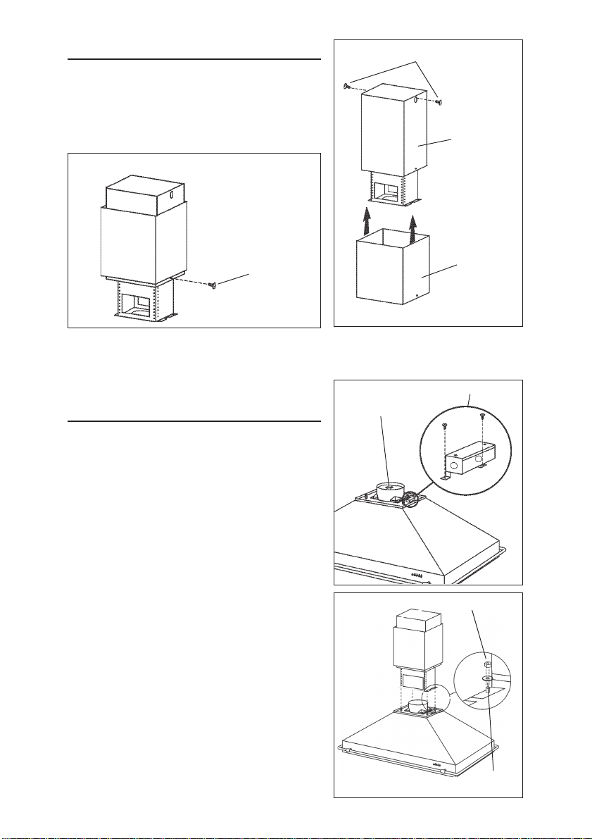
CONNECT DECORATIVE FLUE
1. Secure the upper flue to the upper support
frame with the mounting screws
(3.9x9.5mm).
2. Insert the lower flue moving it completely
towards the top and fix it temporarily with
retaining screws (3.9x9.5mm).
INSERT THE LOWER FLUE
MOUNTING SCREWS
(3.9x9.5mm)
UPPER FLUE
RETAINING
SCREWS
(3.9x9.5mm)
MOUNT HOOD TO SUPPORT
FRAME
1. Remove the tape located on the damper.
2. Before mount hood to support frame remove
the wiring box.
3. Use four (4) nuts and four (4) washers
(D.6.4mm) to secure hood to support frame
as shown.
4. Replace wiring box.
REMOVE THE
TAPE
LOWER
FLUE
WIRING BOX
NUT
- 6 -
WASHER
(Ø6.4mm)
Page 7
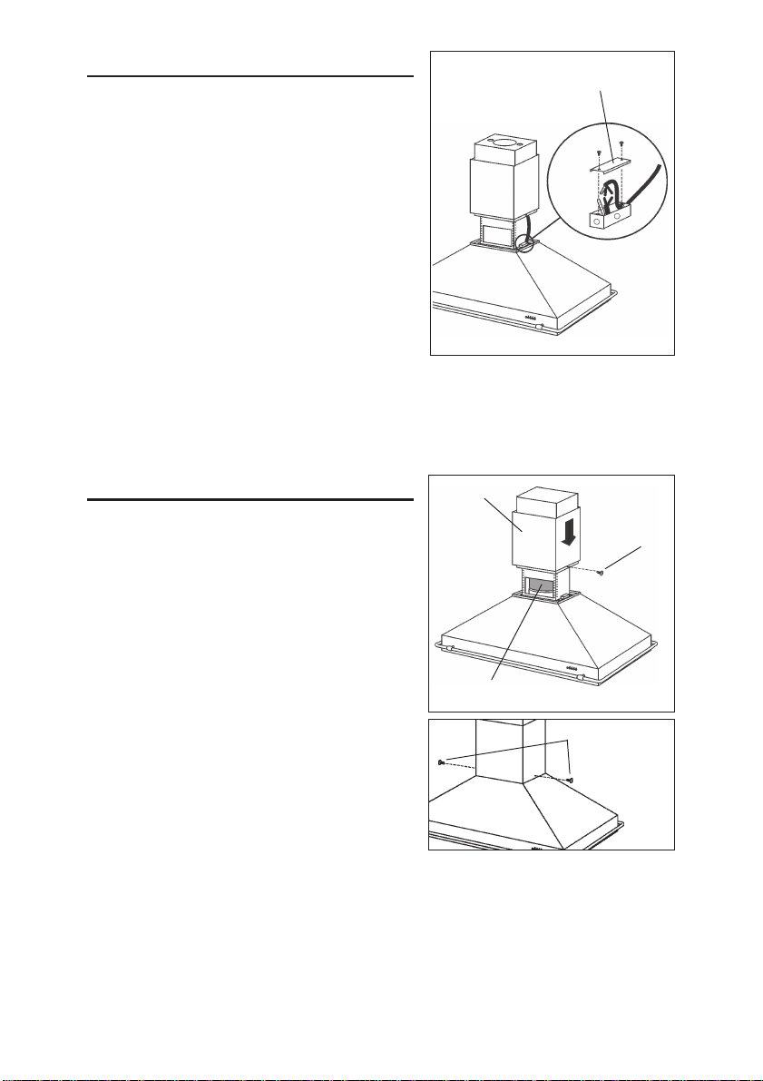
WIRING
Note: This range hood must be properly
grounded. The unit should be installed by a
qualified electrician in accordance with all
applicable national and local electrical
codes.
1. Remove the wiring box cover. Remove a
knockout from the wiring box.
2. Feed 6" of power cable through the knockout opening and secure cable to the wiring
box with an appropriate connector.
3. Make electrical connections. Connect white
to white, black to black and green to green.
4. Replace wiring box cover and screws. Make
sure that wires are not pinched between
cover and box.
WIRING BOX
COVER
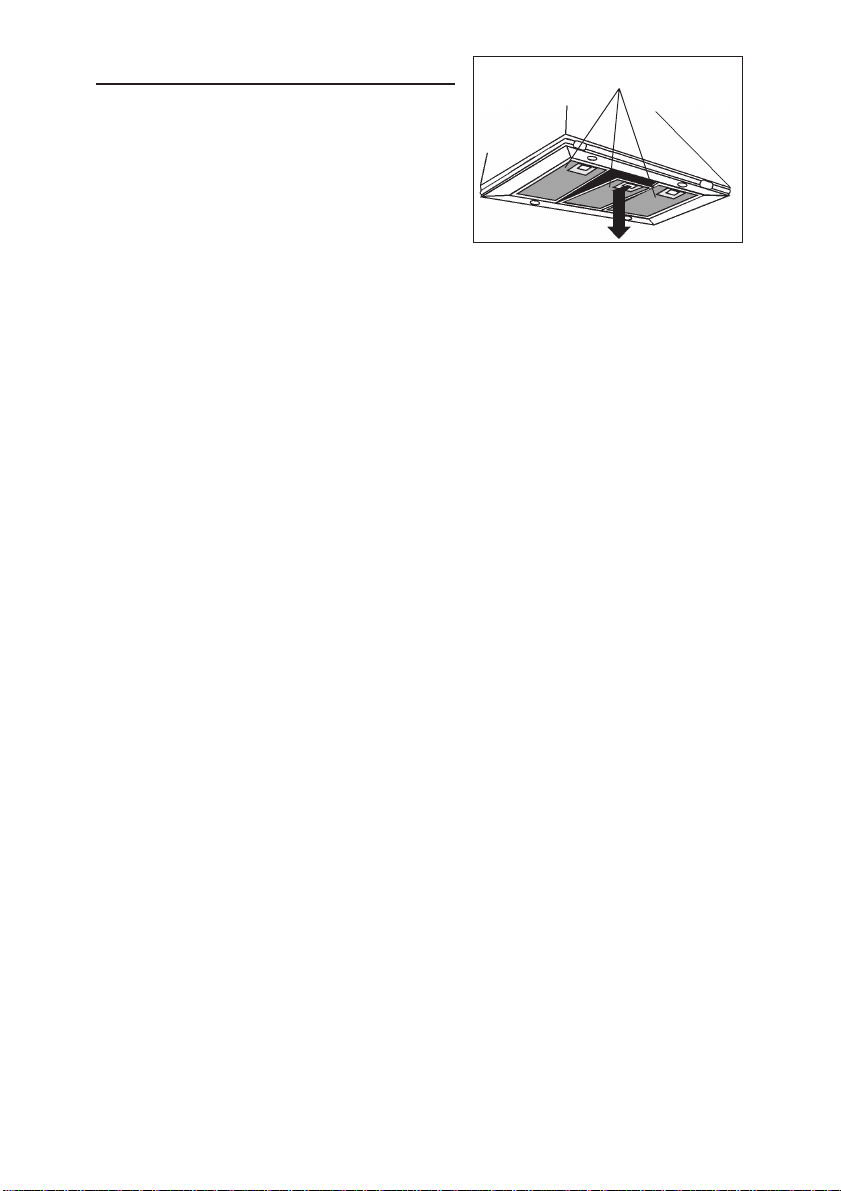
CONNECT DUCTWORK
1. Use 8" round metal duct to connect the
discharge collar on the hood to the ductwork
above.
2. Use duct tape to make all joints secure and
air tight.
3. Remove the two temporary retaining
screws from the lower flue and set it in place
on the hood.
4. Secure decorative flue to hood with two
mounting screws (3.9x9.5mm).
LOWER FLUE
8” ROUND METAL
DUCT
RETAINING
SCREWS
MOUNTING SCREWS
(3.9X9.5MM)
- 7 -
Page 8
MAINTENANCE
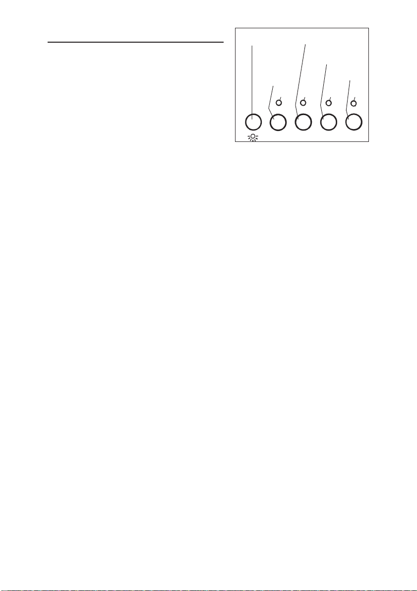
GREASE FILTERS
Grease Filters
The grease filters should be cleaned fre-
quently. Use a warm detergent solution. Grease
filters are dishwasher safe.
To take off the grease filters: at the handle, push
the stop inwards and pull the filters downwards.
Hood Cleaning
Stainless steel is one of the easiest materials to keep clean. Occasional care will
help preserve its fine appearance.
Cleaning tips:
O Hot water with soap or detergent is all that is usually needed.
O Follow all cleaning by rinsing with clear water. Wipe dry with a clean, soft cloth to
avoid water marks.
O For discolorations or deposits that persist, use a non-scratching household cleanser
or stainless steel polishing powder with a little water and a soft cloth.
O For stubborn cases, use a plastic scouring pad or soft bristle brush together with
cleaser and water. Rub lightly in direction of polishing lines or "grain" of the
stainless finish. Avoid using too much pressure which may mar the surface.
O DO NOT allow deposits to remain for long periods of time.
O DO NOT use ordinary steel wool or steel brushes. Small bits of steel may adhere
to the surface causing rust.
O DO NOT allow salt solutions, disinfectants, bleaches, or cleaning compounds to
remain in contact with stainless steel for extended periods. Many of these compounds contain chemicals which may be harmful. Rinse with water after exposure and wipe dry with a clean cloth.
Painted surfaces should be cleaned with warm water and mild detergent only.
- 8 -
Page 9
BLOWER
ON-OFF /
SPEED 1
LED
BLOWER
SPEED 2
LED
BLOWER
SPEED 3
BLOWER
SPEED 4
LED
LED
OPERATION
Controls
The hood is operated using the (5) push-buttons located at eye-level, on the front edge of
the hood.
LIGHT
SWITCH
The light switch turns the halogen lights on
and off. Push the light switch once to turn the
lights ON - push a second time to turn the
lights ON to a brighter level - push a third
time to turn the lights OFF.
0-1
23
4
The blower on-off / speed 1 switch turns the blower on to its lowest running
speed. To turn OFF the blower, push in and hold this blower switch for approximately
2 seconds.
The blower speed 2 switch turns the blower on to medium-low running speed.
Pressing this switch a second time sets a timer which keeps the blower operating
at this speed for 10 minutes. The LED will blink during this time and the blower will
shut off automatically.
The blower speed 3 and blower speed 4 switches operate the same as blower
speed 2 switch except: Blower speed 3 is medium-high and blower speed 4 is
high.
After every 30 hours of operation, the LED above the “blower speed 1 switch” will
be illuminated (RED) and blink for 30 seconds after turning off the blower. This is
a reminder to clean the grease filters. Once the grease filters are cleaned and
installed, press in and hold the “light switch” button for approximately 2 seconds
during the blink of the LED.
HEAT SENTRY™
Your hood is equipped with a HEAT SENTRY™ thermostat. This thermostat is a
device that will turn on or speed up the blower if it senses excessive heat above
the cooking surface.
1) If blower is OFF - it turns blower ON to HIGH speed.
2) If blower is ON at a lower speed setting - it turns blower up to HIGH speed.
When the temperature level drops to normal, the blower will return to its original
setting.
WARNING
The HEAT SENTRY thermostat can start the blower even if the hood is turned
OFF. When this occurs, it is impossible to turn the blower OFF with its switch.
If you must stop the blower, do it from the main electrical panel.
- 9 -
Page 10
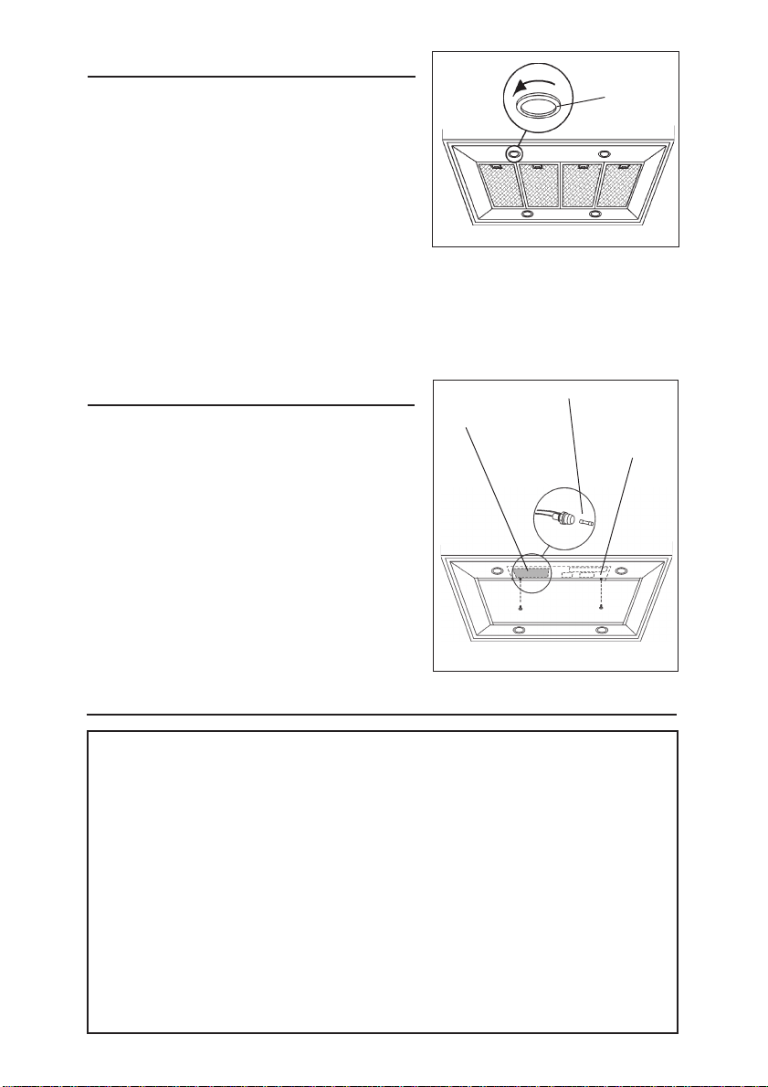
HALOGEN BULBS
This range hood requires four (4) halogen bulbs
(Type JC, 12Volt, 20Watt Max, G-4 Base).
ALWAYS SWITCH OFF THE ELECTRICITY
SUPPLY BEFORE CARRYING OUT ANY
OPERATIONS ON THE APPLIANCE.
To change bulbs:
1. Loosen the ring nut by turning it
counterclockwise.
2. Remove the bulb by pulling sideward - DO
NOT ROTATE. CAUTION: BULB MAY BE HOT!
3. Replace with Type JC, 12Volt, 20Watt Max, G-4 Base halogen bulb. Do not
touch replacement bulb with bare hands!
RING NUT
FUSE REPLACEMENT
SWITCH OFF THE ELECTRICITY SUPPLY.
Remove the grease filters.
ELECTRICAL
BOX
FUSE/S
ELECTRICAL
BOX
SUPPORT
Remove the electrical box support and open
the electrical box.
Replace with the same type of fuse (5x20mm,
4A, 125V).
WARRANTY
Broan warrants to the original consumer purchaser of its products that such products will be free from defects in
materials or workmanship for a period of one year from the date of original purchase. THERE ARE NO OTHER
WARRANTIES, EXPRESS OR IMPLIED, INCLUDING, BUT NOT LIMITED TO, IMPLIED WARRANTIES OR MERCHANT ABILITY OR FITNESS FOR A PARTICULAR PURPOSE.
During this one-year period, Broan will, at its option, repair or replace, without charge, any product or part which is
found to be defective under normal use and service.
THIS WARRANTY DOES NOT EXTEND TO FLUORESCENT LAMP STARTERS AND TUBES. This warranty does
not cover (a) normal maintenance and service or (b) any products or parts which have been subject to misuse,
negligence, accident, improper maintenance or repair (other than by Broan), faulty installation or installation contrary to recommended installation instructions.
The duration of any implied warranty is limited to the one-year period as specified for the express warranty. Some
states do not allow limitation on how long an implied warranty lasts, so the above limitation may not apply to you.
BROAN’S OBLIGATION TO REPAIR OR REPLACE, AT BROAN’S OPTION, SHALL BE THE PURCHASER’S SOLE
AND EXCLUSIVE REMEDY UNDER THIS WARRANTY. BROAN SHALL NOT BE LIABLE FOR INCIDENTAL, CONSEQUENTIAL OR SPECIAL DAMAGES ARISING OUT OF OR IN CONNECTION WITH PRODUCT USE OR PERFORMANCE. Some states do not allow the exclusion or limitation of incidental or consequential damages, so the
above limitation or exclusion may not apply to you.
This warranty gives you specific legal rights, and you may also have other rights, which vary from state to state. This
warranty supersedes all prior warranties.
To qualify for warranty service, you must (a) notify Broan at the address stated below or telephone: 1-800-637-1453,
(b) give the model number and part identification and (c) describe the nature of any defect in the product or part. At
the time of requesting warranty service, you must present evidence of the original purchase date.
BEST BY BROAN, P.O. Box 140 Hartford, Wisconsin 53027
BROAN ONE YEAR LIMITED WARRANTY
- 10 -
Page 11

LISEZ ET CONSERVEZ CES INSTRUCTIONS
!
SEULEMENT POUR UTILISATION DOMESTIQUE
!
AVERTISSEMENTS
POUR REDUIRE LES RISQUES D’INCENDIE, DE DECHARGES ELECTRIQUES OU
DE DOMMAGES AUX PERSONNES, OBSERVEZ LES INSTRUCTIONS SUIVANTES:
1. N’utilisez cet appareil que comme cela est indiqué par le constructeur. Si vous avez des
problèmes, contactez le fabriquant à l’adresse ou au numéro de téléphone indiqués dans
la garantie.
2. Avant de pourvoir à l’entretien ou au nettoyage de votre appareil, éteignez-le au tableau
des commandes ou bloquez le tableau des commandes afin d’éviter de le mettre en marche
accidentellement. Si vous ne pouvez pas bloquer le système permettant d’éteindre votre
appareil, appliquez un avertissement extérieur d’une façon sure, comme par exemple un
panneau, sur le tableau des commandes.
3. L’assemblage et la connexion électrique doivent être faits par des personnes qualifiées
en respectant les normes et règlements en vigueur, y compris les normes et règlements
concernant les possibilités d’incendie.
4. Il est indispensable qu’il y ait suffisamment d’air pour que la combustion et l’évacuation des
gaz à travers le tuyau du brûleur du combustible ait lieu sans retour de flamme. Suivez
les indications données par le fabricant du brûleur ainsi que les normes de sécurité comme
celles qui sont publiées par l’Association Nationale pour la Protection contre les Incendies
National Fire Protection Association (NFPA) et la American Society for Heating, Refrigeration
and Air Conditioning Engineers (ASHRAE), et les autorités locales en matière de normes.
5. Quand vous coupez ou percez des trous dans le mur ou le plafond, n’abîmez pas les fils
électriques ou autres.
6. Le ventilateur canalisé doit toujours évacuer l’air vers l’extérieur.
7. N’utilisez pas cet appareil avec un appareil contrôlant la vitesse à état solide.
8. Afin de diminuer tout risque d’incendie n’utilisez que des conduits en métal.
9. Votre appareil doit être relié à la terre.
ATTENTION - POUR REDUIRE LES RISQUES D’INCENDIE DES MATIERES GRASSES
QUI SONT EN TRAIN DE CUIRE:
A. Ne laissez jamais ni vos éléments chauffants, ni vos casseroles ou poêles sur le feu
sans les contrôler si vous réglez l’apport de chaleur sur une position élevée. Si vos
casseroles ou poêles débordent cela provoque de la vapeur et des éclaboussures de
graisse qui peuvent prendre feu. Chauffez les huiles lentement à feu bas ou moyen.
B. Faites toujours fonctionner votre hotte quand vous cuisez à des températures élevées
ou quand vous cuisinez des plats flambés. (par ex. crêpes Suzette, Cerises “Jubilé”,
Steack au poivre flambé).
C. Nettoyez régulièrement les ailes de vos ventilateurs. Ne permettez pas que la graisse
s’accumule sur le ventilateur ou sur le filtre.
D. Utilisez des casseroles de taille appropriée. Utilisez toujours des ustensiles de cuisson
dont la taille est appropriée à la surface de votre élément de cuisson.
AVERTISSEMENTS
POUR REDUIRE LES RISQUES DE DOMMAGES AUX PERSONNES AU CAS OÙ VOTRE
CUISINIERE PRENDRAIT FEU, OBSERVEZ LES INSTRUCTIONS SUIVANTES:*
1. ETEINDRE LES FLAMMES à l’aide d’un couvercle le plus hermétique possible, une
plaque à gâteaux, ou un plateau en métal, puis éteindre le brûleur. ATTENTION à NE
PAS VOUS BRÛLER. Si les flammes ne s’éteignent pas immédiatement, SORTEZ ET
APPELEZ LES POMPIERS.
2. NE PRENEZ JAMAIS EN MAIN UNE POÊLE OU UNE CASSEROLE QUI A PRIS FEU
- Vous pourriez vous brûler.
3. N’UTILISEZ PAS D’EAU, ni torchons ou serviettes mouillés - vous provoqueriez une
violente explosion de vapeur.
- 11 -
Page 12

4. Utilisez un extincteur SEULEMENT si:
A. Vous savez que vous avez un extincteur Classe ABC, et vous en connaissez déjà le
mode d’emploi.
B. Ce n’est pas un très gros incendie et qu’il se limite à l’endroi où il a explosé.
C. Vous êtes en train d’avertir les pompiers.
D. Vous avez la possibilité d’essayer d’éteindre l’incendie en ayant le dos tourné vers
une issue.
* D’après les “Suggestions concernant la Sécurité contre les incendies des cuisines”
publiées par NFPA.
!
ATTENTION
1. Pour réduire tout risque d’incendie et pour évacuer correctement l’air, assurez-vous de
prévoir un conduit de ventilation extérieur. Ne videz pas l’air dans les espaces limités
par des murs ou des plafonds, les combles, les passages étroits ou les garages.
2. Faites très attention quand vous utilisez des produits de nettoyage ou des détergents.
3. Évitez d’utiliser des aliments pouvant s’enflammer sous la Range Hood.
4. N’utilisez cet appareil que pour une ventilation générale. Ne l’utilisez pas pour évacuer
des matières ou des vapeurs dangereuses ou qui peuvent exploser.
5. Pour éviter de causer des dommages au moteur et de rendre les rotors bruyants et/ou
non équilibrés, évitez que les sprays pour murs secs, la poussière de construction
entrent en contact avec la partie électrique.
6. Le moteur de votre hotte a un thermostat qui éteindra automatiquement le moteur s’il est
surchauffé. Le moteur se remettra en marche lorsqu’il se sera refroidi. Si le moteur
continue à s’éteindre et à se remettre en marche, faites vérifier votre hotte.
7. Pour mieux capturer les impuretés de cuisine, le bas de votre hotte devrait être à une
distance minimum de 24” et à une distance maximum de 30” au-dessus du plan de
cuisson.
8. Vu que cette hotte est grande et lourde, il est recommandé de confier l’installation de
cette hotte à 3 personnes.
9. Ce produit est doté d’un thermostat qui active automatiquement le moteur. Pour
réduire le risque de dommages et éviter l’activation accidentelle, positionner l’interrupteur
du panneau de service sur la position OFF et bloquer le panneau de service ou mettre
un avertissement externe, par exemple une plaquette.
10. Utiliser uniquement avec un kit de connexion pour alimentation homologué.
11. Nous vous recommandons de lire l’étiquette indiquant les caractéristiques de votre
hotte pour de plus amples informations et exigences.
- 12 -
Page 13

PREPAREZ LA HOTTE
Enlever la hotte dans l’emballage et controller le
contenu.
Vous devez recevoir :
1 - Hotte
1 - Conduit décoratif
1 - Structure de support
1 - Sachet (B080810610) avec:
4 - Vis d’assemblage (6 x 70mm)
8 - Rondelles Ø 6.4mm
4 - Rondelles Ø 4.5mm
10 - Vis d’assemblage (3.9 x 9.5mm Tête ronde)
4 - Ecrous
1 - Instructions pour l’installation
1 - Garantie
8 RONDELLES
Ø6.4mm
4 RONDELLES
Ø4.5mm
4 ECROUS
CONDUIT
DECORATIF
10 VIS
D’ASSEMBLAGE
(3.9x9.5mm
Tête ronde)
STRUCTURE DE
SUPPORT
4 VIS D’ASSEMBLAGE
(6x70mm)
- 13 -
Page 14

INSTALLATION DU SYSTEME
D’EVACUATION
REMARQUE: Pour réduire les risques
d’incendie, n’utilisez que des tuyaux en métal.
1. Décidez où le tuyau doit être installé, entre
votre hotte et l’extérieur.
2. Un tuyau droit et court permettra à votre hotte
de fonctionner d’une façon plus efficace.
3. Un tuyau long avec des coudes et des
transitions réduira le bon fonctionnement de
votre hotte. En utiliser le moins possible.
4. Installez un couvercle sur le toit ou au mur.
Reliez un tuyau en acier rond de 8” au
couvercle et faites-le aller jusqu’à l’emplacement de votre hotte. Rendez les jonctions
du tuyau hermétiques au moyen d’un ruban
pour tuyaux.
COUVERCLE DU TOIT
COUDE ROND
HOTTE
DE 24”(61cm) À 30”
(76cm) AU-DESSUS
DU PLAN DE CUISSON
TUYAU ROND
DE 8”
DE 8”
CONDUIT
DÉCORATIF
TROU
D’ÉVA-
CUATION
INSTALLATION DU SYSTEME
DE SUPPORT
1. Installez, à l’emplacement de votre hotte,
un cadre croisé de 2 x 4 entre les solives
du plafond en suivant les dimensions qui
vous sont indiquées.
2. Perfectionnez la surface du plafond.
Assurez-vous de bien marquer l’emplacement des solives et du cadre croisé au
plafond.
3. Placez la structure de support de sorte
que l’ouverture de la structure de support
soit sur le côté le plus long de votre hotte.
4. Fixez la structure de support aux solives et
au cadre croisé au moyen des quatre vis
(6x70mm) et quatre rondelles (D.6.4mm).
Assurez-vous que les vis soient bien
centrées dans les solives et dans le cadre
croisé de sorte que le tout soit bien solide.
5. Réglez la hauteur totale de la structure de
support. Désserrez et resserrez les 4 vis
dans les fissures permettant de régler la
hauteur selon ce qui est nécessaire.
Installez 4 vis (3.9x9.5mm) et 4 rondelles
(D.4.5mm) qui se trouvent à l’intérieur du
sachet accessoires. Considérez que #4 vis
et #4 rondelles doivent être installées sur
le devant, et #4 vis et #4 rondelles doivent
être installées sur la face opposée (arrière).
SURFACE DU
PLAFOND
107/8”
RONDELLES
(Ø6.4mm)
FISSURE POUR
RÉGLAGE EN
HAUTEUR
VUE DE HAUT DU CADRE CROISÉ
107/8” (27.6cm)
CADRE CROISÉ
STRUCTURE
DE SUPPORT
SOLIVES DU
VIS
D’ASSEMBLAGE
(6x70mm)
PLAFOND
DEVANT
Considérez que la hauteur de votre hotte
est de 13¾” (35cm) et que le bas de votre
hotte doit être à entre 24” et 30” au
maximum au-dessus du plan de cuisson.
- 14 -
13
/16”
7
(19.8cm)
Page 15

ASSEMBLAGE DU CONDUIT
DECORATIF
1. Fixez le conduit supérieur à la structure de
support du haut avec les vis d’assemblage
(3.9x9.5mm).
2. Installer le conduit inférieur pour qu’il
touche le plafond et le fixer provisoirement
à l’aide des vis d’assemblage (3.9x9.5mm).
INSTALLER LE CONDUIT
INFERIEUR
VIS D’ASSEMBLAGE
(3.9x9.5mm)
CONDUIT
SUPERIEUR
VIS
D’ASSEMBLAGE
(3.9x9.5mm)
ASSEMBLAGE DE VOTRE
HOTTE A LA STRUCTURE DE
SUPPORT
1. Enlever le ruban positionné sur le clapet.
2. Avant l’assemblage de votre hotte a la
structure de support enlever la boîte de
installation electrique.
3. Fixez votre hotte à la structure de support,
comme cela est indiqué, au moyen des
quatre (4) écrous et quatre (4) rondelles
(D.6.4mm).
4. Remettez a boîte de installation electrique.
ENLEVER LE
RUBAN
CONDUIT
INFERIEUR
BOITE DE CONNEXION
ELECTRIQUE
BOULON
- 15 -
RONDELLES
(Ø6.4mm)
Page 16

INSTALLATION ELECTRIQUE
Remarque: Ce modèle de hotte doit être relié
à la terre correctement. Cet article devrait
être installé par un électricien qualifié selon
les lois nationales et locales en matière
d’électricité.
1. Enlevez le couvercle de la boîte de
connexion électrique. Ouvrez un trou de la
boîte de connexion électrique.
2. Faites passer un câble électrique de 6” dans
le trou et fixez le câble à la boîte de
connexion au moyen d’un connecteur
approprié.
3. Faites le raccordement électrique. Reliez le
blanc au blanc, le noir au noir et le vert au
vert.
4. Remettez le couvercle de la boîte de
connexion et les vis. Assurez-vous que les
fils se sont pas coincés entre le couvercle et
la boîte.
COUVERCLE DE LA
BOITE DE CONNEXION
ELECTRIQUE
CONNEXION DU SYSTEME
D’EVACUATION
1. Reliez le collier d’évacuation qui se trouve
sur votre hotte au système d’évacuation qui
se trouve au-dessus au moyen d’un tuyau
rond en métal de 8” (20cm).
2. Utilisez du ruban pour tuyauterie afin de
rendre toutes les jonctions sures et étanches.
3. Déposer les 2 vis d’assemblage provisoires
du conduit inférieur et poser le conduit sur
la hotte.
4. Fixez le conduit inférieur à votre hotte au
moyen des 2 vis d’assemblage
(3.9x9.5mm).
CONDUIT
INFERIEUR
TUYAU ROND EN METAL
DE 8” (20CM)
VIS
D’ASSEMBLAGE
VIS D’ASSEMBLAGE
(3.9X9.5MM)
- 16 -
Page 17

ENTRETIEN
FILTRES ANTI-GRAISSE
Filtres anti-graisse
Les filtres anti-graisse doivent être nettoyés
fréquemment. Utilisez une solution contenant
un détergent tiède. Les filtres anti-graisse
peuvent être lavés au lave-vaisselle.
Pour enlever les filtres anti-graisse: à l'aide de
la poignée, pousser l’arrêt vers l’intérieur et tirer
le filtre vers le bas.
Nettoyage de votre hotte
L’acier inoxydable est une des matières les plus faciles à nettoyer. Un entretien de
temps en temps permettra de le conserver en parfait état. Conseils pour le nettoyage:
O Eau chaude et savon ou détergent est tout ce qui est normalement nécessaire.
O Après chaque nettoyage, rincez bien à l’eau claire. Essuyez avec un chiffon
propre et doux afin d’éviter les taches d’eau.
O Si des décolorations ou des dépôts persistent, utilisez un nettoyant domestique non
abrasif ou de la poudre pour l’acier inoxydable et un peu d’eau et un chiffon doux.
O Dans les cas difficiles, utilisez une éponge en plastique ou une brosse douce avec du
nettoyant et de l’eau. Frottez légèrement en suivant la direction du polissage ou du
“grain” de l’acier inoxydable. Evitez de frotter trop fort afin de ne pas abîmer la surface.
O NE LAISSEZ PAS les taches trop longtemps.
O N’UTILISEZ PAS de laines d’acier ordinaires ou des brosses en acier. Des débris
d’acier pourraient adhérer à la surface et causer de la rouille.
O NE PERMETTEZ PAS que des solutions salées, des désinfectants, des
blanchissants ou des produits nettoyants restent en contact avec l’acier pendant
longtemps. Beaucoup de ces produits contiennent des produits chimiques qui
pourraient causer des dommages. Rincez à l’eau immédiatement s’ils entrent en
contact et essuyez avec un chiffon humide.
Les surfaces peintes doivent être nettoyées avec de l’eau tiède additionnée d’un
détergent doux seulement.
- 17 -
Page 18

FONCTIONNEMENT
Commandes
Votre hotte fonctionne grâce aux (5) boutons
sur lesquels vous devez appuyer et qui se
trouvent à la hauteur de vos yeux, sur le devant
de votre hotte.
BOUTON
DE LA
LUMIERE
VENTILATEUR
VITESSE 2
VENTILATEUR
ON/OFF
VITESSE 1
LED
VENTILATEUR
VITESSE 3
VENTILATEUR
VITESSE 4
LED
LED
LED
Le bouton de la lumière allume et éteint les
lampes halogènes. En pressant 1 fois la
touche, la lumière s’allume au 1er niveau; en
pressant 2 fois la touche, la lumière du 2
niveau s’allume (éclairage plus intense); en
ème
0-1 2
34
pressant encore une fois la touche, la lumière
s’éteint.
Le bouton ON/OFF vitesse 1 du ventilateur fait fonctionner le ventilateur à la
vitesse la plus basse. Vous éteignez le ventilateur appuyant sur le bouton pendant
2 secondes environ.
Le bouton deuxième vitesse fait fonctionner le ventilateur à une vitesse
moyennement basse. En appuyant une deuxième fois sur ce bouton vous faites
fonctionner un timer qui fera fonctionner le ventilateur à cette vitesse pendant 10
minutes. Le voyant lumineux clignotera pendant tout ce temps et le ventilateur
s’arrêtera automatiquement.
Les boutons du ventilateur 3ème et 4ème vitesse font fonctionner ce dernier
comme le bouton deuxième vitesse avec la différence que le bouton 3ème vitesse
est une vitesse moyennement élevée et le bouton 4ème vitesse est une vitesse
élevée.
Au bout d'environ 30 heures de fonctionnement, le LED rouge du “Bouton -vitesse
1” se mette à clognoter; cela indique que les filtres anti-graisse doivent être
nettoyées. Après avoir remonté les filtres anti-graisse propres, appuyez sur le
bouton de la lumière pendant 2 secondes environ, au même temps les voyants
lumineux clignotons
HEAT SENTRY
MC
Votre hotte est munie d’un thermostat HEAT SENTRYMC. Ce thermostat est un
dispositif qui actionnera ou augmentera la vitesse du ventilateur s’il détecte une
chaleur excessive au-dessus de la surface de cuisson.
1) Si le ventilateur n’est pas en marche - il actionnera le ventilateur en haute
vitesse.
2) Si le ventilateur fonctionne en basse vitesse - le ventilateur tournera en haute
vitesse.
Lorsque la température revient à la normale, le ventilateur retourne à sa vitesse
d’origine.
AVERTISSEMENT
Le thermostat HEAT SENTRY
MC
peu actionner la hotte même si la hotte est
arrêtée. Si tel est le cas, il est impossible de l’arrêter avec l’interrupteur. Si
vous devez arrêter le ventilateur, faites-le à partir du panneau électrique
principal.
- 18 -
Page 19

AMPOULES HALOGENES
Ce modèle de hotte veut quatre (4) ampoules
BAGUE
halogènes (Type JC, 12Volt, 20Watt Max, G-4
Base).
AVANT DE PROCÉDER À QUELCONQUE
OPÉRATION, DÉBRANCHEZ L’APPAREIL.
Pour changer les ampoules:
1. Dévissez la bague dans le sens contraire
aux aiguilles d’une montre.
2. Enlevez l’ampoule en tirant sur le côté (NE
LA FAITES PAS TOURNER). ATTENTION:
L’AMPOULE PEUT ETRE CHAUDE!
3. Remplacer par une ampoule ayant les mêmes caractéristiques (Type JC, 12Volt,
20Watt Max, G-4 Base). Ne touchez pas l’ampoule neuve de vos mains nues!
REMPLACEMENT FUSIBLE
DÉBRANCHEZ L’APPAREIL.
Enlevez les filtres anti-graisse.
BOÎTER
INSTALLATION
ELECTRIQUE
FUSIBLE/S
SUPPORT
BOÎTER
INSTALLATION
ELECTRIQUE
Démontez le support boîtier installation
électrique et ouvrir le boîtier installation
électrique.
Remplacez par un fusible du même type
(5x20mm, 4A, 125V).
GARANTIE
Broan garantit au consommateur-acheteur de ses produits que ces produits seront sans défauts concernant les
matières employées et concernant la fabrication pendant une période d’un an à partir de la date d’achat. IL N’Y A
AUCUNE AUTRE GARANTIE, EXPLICITE OU IMPLICITE, Y COMPRIS, MAIS NON PAS LIMITEE A, LES GARANTIES
IMPLICITES OU CONCERNANT LA CAPACITE COMMERCIALE OU LA CONVENANCE POUR TOUT BUT
PARTICULIER. Pendant cette période d’un an, Broan réparera ou remplacera, s’il le jugera nécessaire, gratuitement,
tout article ou toute pièce qui résulteront défectueux à condition qu’ils aient été utilisée et entretenu correctement.
CETTE GARANTIE NE S’ETEND PAS AUX TUBES ET AUX INTERRUPTEURS DES LAMPES FLUORESCENTES.
Cette garantie ne couvre pas (a) l’entretien normal ni (b) tout article ou toute pièce qui aient subi une utilisation
erronée, une négligence, un accident, un entretien erroné ou une réparation (autre que de la part de Broan), une
installation défectueuse ou bien une installation ne respectant pas les instructions d’installation recommandées.
La durée de toute garantie implicite est limitée à un an comme cela est spécifié dans la garantie explicite. Quelques
états ne permettent pas de limites quant à la durée d’une garantie implicite, par conséquent la limitation indiquée cidessus peut ne pas vous concerner.
L’OBLIGATION DE REPARER OU DE REMPLACER DE LA PART DE BROAN SERA LE SEUL ET EXCLUSIF REMEDE
DE L’ACHETEUR COUVERT PAR CETTE GARANTIE. BROAN NE SERA PAS RESPONSABLE DES DOMMAGES
ACCIDENTELS, CONSEQUENTIELS OU SPECIAUX DUS A L’UTILISATION DU PRODUIT OU A SA PERFORMANCE
OU EN ETANT LA CONSEQUENCE. Quelques états ne permettent pas l’exclusion ou la limitation des dommages
accidentels ou conséquentiels, par conséquent la limitation indiquée ci-dessus peut ne pas vous concerner. Cette
garantie vous donne des droits légaux spécifiques, et vous pouvez aussi avoir d’autres droits, qui varient d’Etat à
Etat. Cette garantie dépasse toute garantie précédente. Pour avoir droit à la garantie, vous devez (a) avertir la Maison
Broan à l’adresse indiquée ci-dessous ou téléphoner : 1-800-637-1453, (b) donner le numéro du modèle et l’identification
de la pièce défectueuse et (c) décrire la nature de tout défaut de l’article ou de la pièce. Au moment où vous demandez
le service de garantie, vous devez présenter la preuve d’achat avec la date.
BEST BY BROAN, P.O. Box 140 Hartford, Wisconsin 53027
GARANTIE BROAN LIMITÉE À UN AN
- 19 -
Page 20

LEA Y CONSERVE ESTAS INSTRUCCIONES
!
INDICADO PARA EL USO EN COCINAS DOMESTICAS
!
ADVERTENCIA
PARA EVITAR EL RIESGO DE INCENDIO, CORTOCIRCUITO O DAÑO PARA LAS
PERSONAS, OBSERVE ATENTAMENTE LAS SIGUIENTES NORMAS:
1. Use esta unidad solamente de la manera indicada por el fabricante; si tiene dudas,
póngase en contacto con éste a la dirección o teléfono indicados en la garantía.
2. Antes de hacer una revisión o de limpiar la unidad, desconéctela de la red para evitar
que se encienda de manera accidental. En el caso de que éste no pueda ser desactivado, se indicará nel panel de servicio.
3. El montaje y la instalación eléctrica debe hacerlos un técnico especializado siguiendo
las normas estándar e incluyendo aquellas de construcción anti incendio.
4. Necesita aire suficiente para una apropiada combustión y escape de gases a través del
tubo del depósito de quema de combustible. Para evitar que el humo aspirado vuelva a
la cocina, siga las directivas del fabricante y las normas estándar de siguridad así como
las normas publicadas por la Asociación de prevención de incendios (NFPA) y la Sociedad americana de especialistas en cale-facción, refrigeración y aire acondicionado y
además las normas de las autoridades locales.
5. Hacer un corte o un taladro en la pared o en el techo no debe dañar la instalación
eléctrica u otras instalaciones ocultas en la pared.
6. Los conductos ventiladores deben siempre desalojar al exterior.
7. No use esta unidad con dispositivo de control de la velocidad a estado sólido.
8. Para evitar el riesgo de incendio, use solamente conductos de metal.
9. Esta unidad tiene que ser conectada a tierra.
PARA EVITAR EL RIESGO DE FUEGO POR ALTO NIVEL DE GRASA:
A. Nunca abandone los quemadores con el fuego alto. La cocción causa humo y restos
de grasa que pueden arder. Caliente el aceite a fuego medio o bajo.
B. Encienda siempre la campana cuando cocine a fuego alto o cuando cocine alimentos
fácilmente inflamables. (por ejemplo Crepes Suzette, Cerezas Jubilee, Ternera
flambeada con granos de pimienta).
C. Limpie con frecuencia los ventiladores. No se debe acumular grasa en el ventilador o
en el filtro.
D. Usa el tamañp de cazuela apropiado. Use siempre utensilios de cocina de tamaño y
material adecuados.
ADVERTENCIA
PARA EVITAR EL RIESGO DE DAÑOS A PERSONAS EN CASO DE FUEGO POR ALTO
NÍVEL DE GRASA, TENGA EN CUENTA LO SIGUIENTE:*
1. SOFOQUE LA LLAMA con una tapadera apropiada, una bandeja metálica ó un utensilio
de cocína que pueda cubrirla, despues, apague el quemador. ACTÚE CON
PRECAUCÍON PARA EVITAR QUEMADURAS. Si la llama no se extingue inmediatamente, SALGA Y LLAME A LOS BOMBEROS.
2. NUNCA COJA UNA SARTEN EN LLAMAS, porque corre el riesgo de quemarse.
3. NO USE AGUA ni paños o toallas húmidas porque puede provocarse una violenta
humareda.
4. Use un extintor SOLAMENTE si:
A. Posee un extintor de clase ABC y sabe perfectamente cómo usarlo.
B. El fuego es pequeño y está controlado en el mismo sitio en que empezó.
C. Ha llamado con anterioridad a los bomberos.
D. Puede combatir el fuego retrocedíendo hacia la salida.
* Basado en “Seguridad antifuego en la cocína” publicado por NFPA.
- 20 -
Page 21

!
ADVERTENCIA
1. Para reducir el riesgo de incendios y para evacuar correctamente los humos, asegurarse
de haber realizado una conducción del aire hasta el exterior. No expulsar los humos en
espacios cerrados por paredes o techos, áticos, espacios angostos o garajes.
2. Prestar la máxima atención al utilizar productos de limpieza o detergentes.
3. Evitar el uso de productos alimentarios que puedan inflamarse bajo la campana.
4. Sólo para ventilación total. No use gases de escape peligrosos o materiales y vapores
explosivos.
5. Para evitar daños en el funcionamiento del motor e impulsores ruidosos y/o desequilibrados, mantenga alejados de la unidad de encendido pulverizadores en seco o polvo.
6. El motor tiene un nivel de sobrecarga térmica que apaga automáticamente el motor
cuando se ha recalentado excesivamente. El motor se pone de nuevo en fincionamento
cuando la temperatura baja. Si el motor comienza a encenderse y a apagarse, deberá
hacer una revisión de éste.
7. Para limpiar mejor las impurezas al cocinar, la distancia entre la parte inferior de la
campana y la zona de cocción debe ser mínimo 24” - maximo 30”.
8. Debido a su gran tamaño y peso, se recomienda su montaje por parte de 3 técnicos
esperializados.
9. Este producto está dotado de un termostato que pone en marcha automáticamente el
motor. Para reducir el riesgo de daños y evitar que se encienda accidentalmente,
colocar el interruptor del panel de servicio en la posición OFF y bloquear el panel de
servizio o colocar una advertencia externa como por ejemplo un letrero o una chapita.
10.Use solamente con juego de conexión para alimentación aprobado.
11.Se recomienda leer la placa de caracteristicas del producto para ulterior información.
- 21 -
Page 22

PREPARE LA CAMPANA
Sacar la campana de l’embalaje y controlar el
contenido.
Recivireis:
1 - Campana
1 - Tubo decorativo
1 - Armazón de soporte
1 - Bolsita (B080810610) con:
4 - Tornillos de montaje (6 x 70mm cabeza
redonda)
8 - Arandelas Ø 6.4mm
4 - Arandelas Ø 4.5mm
10 - Tornillos de montaje (3.9 x 9.5mm cabeza
redonda)
4 - Tuercas
1 - Instrucciones para instalación
1 - Garantia
8 ARANDELAS
Ø6.4mm
4 ARANDELAS
Ø4.5mm
4 TUERCAS
TUBO
DECORATIVO
10 TORNILLOS
DE MONTAJE
(3.9x9.5mm
cabeza redonda)
ARMAZÓN DE
SOPORTE
- 22 -
4 TORNILLOS DE
MONTAJE (6x70mm)
Page 23

INSTALACION DEL TUBO DE
EXTRACCION
NOTA: para evitar el riesgo de incendio, use
solamente material de metal.
1. Decida donde va a colocar el tubo de
extracción entre la campana y la parte
exterior.
2. Un recorrido de tubo corto y recto permitirá
a la campana funcionar de manera más
eficaz.
3. Los recorridos largos de tubo, codos y
manguitos impiden el buen funcionamiento
de la campana. Use el menor número de
ellos posible.
4. Instale una cubierta ó una tapa. Una el tubo
de acero de 8” de diámetro a la cubierta y
retroceda hasta la posición de la campana.
Use une cinta para precintar las juntas entre
las partes del entubado.
INSTALACION DEL SISTEMA
DE SUJECION
1. En el sitio donde vaya a ir la campana,
instale un entramado entre las vigas del
techo utilizando las medidas dadas.
2. Termine la superficie del techo. Asegúrese
de marcar la colocación de las vigas del
techo y del entramado.
3. Coloque el armazón de soporte de tal
manera que la abertura de éste se
encuentre en la parte más larga de la
campana.
4. Sujete la mitad superior del armazón de
soporte a las vigas y al entramado con los
cuatro tornillos (6x70mm) y cuatro
arandelas (D.6.4mm). Compruebe que los
tornillos vayan al centro de las vigas del
techo para una mayor rigidez.
5. Ajuste la altura total del armazón de
soporte. Afloje y apriete de nuevo los 4
tornillos en las ranuras de ajuste de la
altura si es necesario.
Introduzca cuatro tornillos y cuatro
arandelas colocados en la bolsita para el
montaje. Tenga en cuenta que #4 tornillos
y #4 arandelas deben ser colocados su la
parte frontal, y #4 tornillos y #4 arandelas
deben ser colocados su la parte posterior.
CUBIERTA DEL TEJADO
TUBO DE 8” DE
DIÁMETRO
MANGUITO
DE 8” DE
DIÁMETRO RESPI-
CAMPANA
24” (61cm) A 30” (76cm)
POR ENCIMA DE LA
ZONA DE COCCIÓN
SUPERFICIE DEL
TECHO
107/8”
ARANDELAS
(Ø6.4mm)
RANURAS DE
AJUSTE DE LA
ALTURA
VISTA SUPERIOR DEL ARMAZÓN DE
TUBO
DECORATIVO
ARMAZÓN DE
SOPORTE
SOPORTE
7
/8” (27.6cm)
10
ENTRAMADO
VIGAS
DEL
TECHO
TORNILLOS DE
MONTAJE
(6x70mm)
PARTE
FRONTAL
RADERO
Tenga en cuenta que la campana tiene
13¾” (35cm) de alta y que su parte inferior
debe estar a una altura mínima de 24” y
máxima de 30” con respecto a la zona de
cocción.
- 23 -
13
/16”
7
(19.8cm)
Page 24

INSTALACION DEL TUBO
DECORATIVO
1. Sujete el tubo superior a la parte superior
de la estructura de soporte de madera en
la pared con los tornillos para el montaje
(3.9x9.5mm).
2. Introduzca el tubo inferior hasta hacerlo
tocar el techo, y fíjelo momentáneamente
con los tornillos para el montaje
(3.9x9.5mm).
INTRODUZCA EL TUBO
INFERIOR
TORNILLOS PARA EL
MONTAJE (3.9x9.5mm)
TORNILLOS PARA EL MONTAJE
(3.9x9.5mm)
TUBO
SUPERIOR
TUBO
INFERIOR
BASE DE LA CAMPANA PARA
SUJETAR LA ESTRUCTURA
DE MADERA
1. Quitar la cinta adhesiva en la válvula.
2. Antes de instalar la campana a la estructura
quitar la caja de conexión eléctrica.
3. Use cuatro (4) tuercas y cuatro (4)
arandelas (D.6.4mm) para fijar la campana
a la estructura de madera en la pared como
se indica.
4. Reponer la caja de conexion electrica.
QUITAR LA
CINTA
ADHESIVA
CAJA DE CONEXIÓN
ELÉCTRICA
TUERCA
ARANDELAS
(Ø6.4mm)
- 24 -
Page 25

INSTALACION ELECTRICA
Nota: Este tipo de campana tiene que ser
conectada a tierra cuidadosamente. La
unidad debe instalarla un técnico electricista siguiendo las normas nacionales y
locales.
1. Quite la tapa de la caja de conexión
eléctrica y saque un cable.
2. Suministre 6” de cable eléctrico al extremo
y sujete el cable a la caja de conexión
eléctrica con un conector adecuado.
3. Haga las conexiones eléctricas, una blanco
con blanco, negro con negro y verde con
verde.
4. Vuelva a conectar la tapa de la caja de
conexión. Compruebe que los cables no
queden pillados.
TAPA DE CONEXIÓN
ELÉCTRICA
INSTALACION DEL TUBO DE
EXTRACCION
1. Use un tubo de metal de 8” (20cm) de
diámetro para unir el casquillo situado en
la parte superior de la campana con el tubo
de extracción.
2. Use la cinta para unir todas las junturas, de
esta manera el tubo quedará hermético.
3. Remueva los 2 tornillos para el montaje
provisorio del tubo inferior y apoye el tubo
sobre la campana.
4. Sujete el tubo inferior a la campana con los
2 tornillos para el montaje (3.9x9.5mm).
TUBO
INFERIOR
TUBO DE METAL DE 8”
(20CM)DE DIÁMETRO
TORNILLOS
DE
MONTAJE
TORNILLOS
DE
MONTAJE
(3.9X9.5MM)
- 25 -
Page 26

MANTENIMIENTO
FILTROS ANTIGRASA
Filtros antigrasa
Los filtros antigrasa deben limpiarse a
menudo. Use un detergente que no sea fuerte.
Los filtros antigrasa se pueden meter en el
lavavajillas. Para extraer los filtros antigrasa,
empuje de las manillas hacia dentro y tire de
los filtros hacia abajo.
Limpieza de la campana
El acero inoxidable es uno de los meteriales más fáciles de limpiar, pero sería
aconsejable un especial cuidado en su uso para mantenerla en buen estado.
La campana se puede limpiar de las siguientes maneras:
O Agua caliente con jabón o detergente es la mejor manera para limpiarla.
O Aclárela con agua corriente, séquela con un paño suave y limpio para evitar las
huellas que deja el agua.
O Para las manchas o restos de grasa que persistan, use un producto químico
doméstico que no raye ó un limpiador para acero inoxidable con poca agua y un
paño suave.
O Si las manchas persisten, use un estropajo y un cepillo de cerdas suaves con un
producto limpiador y agua. Frote suavemente en el sentido del pulido o de las “vetas”
del remate del inoxidable. No apriete demasiado porque podría dañar la superficie.
O No deje que las manchas se acumulen durante mucho tiempo.
O No use utensilios o cepillos de acero. Pequeñas particulas de acero pueden
adherirse y oxidarse.
O No use soluciones salinas, desinfectantes, lejías, o productos de limpieza que
permanezcan en contacto con el acero inoxidable durante largos periodos de
tiempo. Muchos de estos productos contienen componentes químicos que
podrían resultar nocivos. Aclare con agua y seque con un paño limpio.
Las superficies lacadas deben limpiarse solamente con agua tibia y detergente no
muy fuerte.
- 26 -
Page 27

FUNCIONAMIENTO
Mandos
La campana se pone en funcionamiento
usando los mandos situados a la altura de
los ojos a un lado de la parte frontal de la
campana.
El interruptor luz enciende y apaga las
INTERRUPTOR
LUZ
MANDO DE
ENCENDIDO/
APAGADO Y
VELOCIDAD 1
MANDO DE
VELOCIDAD 2
MANDO DE
VELOCIDAD 3
MANDO DE
VELOCIDAD 4
DIODODIODODIODODIODO
lámparas halógenas. Pulsando la tecla una
vez, la luz se enciende a intensidad 1,
pulsándolo una segunda vez, la luz se
0-1
enciende a intensidad 2 (luz más intensa) y,
234
pulsándolo otra vez más, la luz se apaga
completamente.
El mando de encendido- apagado y velocidad 1 del aspirador pone en
funcionamiento el aspirador a una velocidad mínima. Manteniendo presionado el
mando durante dos segundos aproximadamente, se apaga el aspirador.
El mando de velocidad 2 pone el aspirador a una velocidad media- baja. Si
acciona este mando otra vez se pone en funcionamiento un timer que mantiene el
aspirador funcionando a dicha velocidad durante diez minutos. El diodo se
mantiene encendido durante ese tiempo y el aspirador se apaga automáticamente.
El mando de velocidad 3 y el de velocidad 4 funcionan como el de velocidad 2
pero el de velocidad 3 funciona a una velocidad medio- alta y el de velocidad 4 lo
hace a una velocidad alta.
Después de unas 30 horas de funcionamiento, el diodo rojo del mando “velocidad
1” parpadea, indicando que hay que limpiar los filtros antigrasa.
Una vez vueltos a colocar los filtros limpios, mantenir presionado el interruptor luz
durante dos segundos aproximadamente, mientras que la pantalla o diodos
(espias) parpadean
HEAT SENTRY
MR
Su campana esta equipada con termostato HEAT SENTRYMR. Este termostato
tiene un mecanismo que se encenderáo aceleratáel ventilador si se detecta un
calor excesivo encima de la cocina.
1) Si el ventilador esta apagando - el se prenderá a una velocidad máxima.
2) Si el ventilador esta encendido a una velocidad minima - el se prenderá a una
velocidad máxima.
Cuando la temperatura disminuye a un nivel normal, el ventilador vuelve a la
función de origen.
AVERTENCIA
El HEAT SENTRY
mr
termostato puede comenzar a funcionar al igual si la
campana esta parada. En este caso, es imposible parar el ventilador con los
interruptores. Si usted para la campana, halago a partir del panel eléctrico
principal.
- 27 -
Page 28

LAMPARAS HALOGENAS
Este tipo de campana necesita cuatro (4)
lámparas halógenas (Tipo JC, 12Volt, 20Watt
Max, G-4 Base).
ANTES DE PROCEDER A CUALQUIER
OPERACIÓN, ES NECESARIO
DESCONECTAR EL APARATO.
Para cambiar las lámparas:
1. Destornillar la abrazadera en sentido
antihorario.
2. Extraiga la lámpara oblicuamente (NO LA
GIRE) - ATENCIÓN: LAS LÁMPARAS PUEDEN ESTAR CALIENTES.
3. Sustituir con lámparas del mismo tipo (JC, 12Volt, 20Watt Max, G-4 Base). No
toque la lámpara de repuesto con las manos desnudas.
ABRAZADERA
SUSTITUCION FUSIBLE
DESCONECTAR EL APARATO.
Remover los filtros antigrasa.
CAJA DE LA
INSTALACION
ELECTRICA
FUSIBLE/S
PLACA
INSTALACION
ELECTRICA
Desmontar la placa de la instalación eléctrica
y abrir la caja de la instalación eléctrica.
Sustituir por un fusible del mismo tipo
(5x20mm, 4A, 125V).
GARANTIA
Broan garantiza al consumidor-comprador de sus productos que dichos productos no tendrán defectos en los
materiales o fabricación, durante un periodo de un año a partir de la fecha de la compra. NO HAY OTRO TIPO DE
GARANTIAS QUE INCLUYAN O SE LIMITEN EXCLUSIVAMENTE A GARANTIAS IMPLICITAS O DE CAPACIDAD
COMERCIAL O CONVE-NIENCIA PARA UN PROPOSITO ESPECIFICO.
Durante el periodo de un año, Broan, si lo estima conveniente, reparará o reemplazará sin gastos para el usuario
cualquier producto o parte de éste que sea defectuosos habiéndose usado correctamente. Esta garantía no cubre
las lámparas halógenas ni los tubos. Tampoco cubre el mantenimiento ni los productos o partes de éstos que
hayan sido usados de forma incorrecta, con negligencia, rotos accidentalmente o por una incorrecta manutención
ó reparación (distinta da la realizada por Broan), montaje incorrecto ó instalación que no se ajuste a las instrucciones
de montaje indicadas. Le duración de la garantía se limita al periodo de un año como está especificado en la
garantía explicita. Algunos paises no permiten un limite en la duración de la garantía implicita; si es asi en su
caso, esta limitación arriba indicada podría no aplicarse.
LA PRESENTE GARANTIA CUBRIRA EXCLUSIVAMENTE AL COMPRADOR LOS SERVICIOS DESCRITOS
ANTERIORMENTE. BROAN NO SE HACE RESPONSABLE DE DANOS PRODUCIDOS DE MANERA ACCIDENTAL
O RELACIONADOS CON EL USO INCORRECTO DEL PRODUCTO O SU FUNCIONAMIENTO.
Algunos paises no permiten la exclusión o limitación de los daños producidos de manera accidental, si es así en
su caso, esta limitación arriba indicada podría no aplicarse. Esta garantía le da derechos legales específicos y
podría también disponer de otros derechos que varian de país a país. Esta garantía supera otras garantías dadas
con anterioridad. Para disfrutar de la garantía usted deberá a) Avisar a la dirección abajo indicada ó bien llamar
por teléfono al número 1-800-637-1453 b) Dar el número de serie del modelo correspondiente o bien una descripción
de la parte averiada, c) Descripción del defecto en el producto o bien en una de sus partes. Para requerir un
servicio en garantía debe presentar el justificante con la fecha de la compra.
BEST BY BROAN, P.O. Box 140 Hartford, Wisconsin 53027
GARANTIA BROAN POR UN AÑO
- 28 -
Page 29

SERVICE PARTS
MODEL ISER222 - Parts for stainless steel models shown. For service parts for
black, white, polished brass, or brushed copper models, call Broan Customer Service.
KEY NO. PART NO. DESCRIPTION
9 B08087132 Grease Filter (n. 4)
14 B02300233 Motor Capacitor
16 BE3345732 Electrical Box Support
19 B03295005 Capacitor Protection
26 B02300891 Halogen Lamp Bulb
37 B02300787 Heat Sentry
38 B03292357 Control Board Box
38 BW0000027 Control Boards + Trimming
39 B03294033 Control Board Box Cover
42 B03295001 Flange
48 B02310201 Motor
49 B03295071 Blower Wheel
53 B03202007 Rubber Washer
56 B03292465 Duct Connector
57 B02011004 Damper Flap
62 BE3401922 Blower Mounting Cover
63 BE3343076 Upper Support
68 B02011064 Right Blower Housing
69 B02011063 Left Blower Housing
113 B02011284 Nameplate
115 BE3495228 Wiring Box
116 BE3334252 Wiring Box Cover
118 BE3407823 Decorative Flue Bottom
119 BE3403578 Decorative Flue Top
124 B03120185 Telescopic Structure Bottom
125 B03120186 Telescopic Structure Top
133 B02009290 Utensil Rail
141 B02009301 Side Utensil Rail
144 B03292287 Wire Clamp
147 BR2300135 Terminal Block
156 B02009186 Coupling Sleeve
165 B03295008 Wiring Box
166 B08086662 Circuit Board
208 B02300792 Transformer
223 B03202296 Switch Button
274 B03295035 Fuse Box
474 B02300790 Halogen Lamp Housing
477 B03295006 Closing
* B06002008 Blower Assembly
* B06107579 Switch Box Assembly
998 B080810610 Hardware Package
- B02300782 Fuse
- B02300674 Fuse Holder
(Includes Key Nos. 42, 48, 49, 53, 68, 69)
(Includes Key Nos. 107, 223, 38, 230,234, 67)
* Not shown assembled.
- 29 -
Page 30

LISTE PIECES DE RECHANGE
MODELE ISER222 - Ci-dessous liste pièces de rechange pour hottes en inox.
Pour les pièces de recharge des modèles de couleurs noir, blanc, laiton jaune
poli, cuivre brossé, contacter Broan Customer Service.
KEY NO. PART NO. DESCRIPTION
9 B08087132 Filtre anti-graisse (n.4)
14 B02300233 Condensateur
16 BE3345732 Support boîte installation electrique
19 B03295005 Protection condensateur
26 B02300891 Lampe halogène
37 B02300787 Capteur de température
38 B03292357 Boîte circuit imprimé electrique
38 BW0000027 Circuit imprimé commandes + Enjoliveur
39 B03294033 Couvercle boîte circuit imprimé electrique
42 B03295001 Bride de raccordement
48 B02310201 Moteur
49 B03295071 Turbine du moteur
53 B03202007 Pare chocs
56 B03292465 Bride de raccordement
57 B02011004 Clapet anti-retour
62 BE3401922 Support moteur
63 BE3343076 Support supérieure
68 B02011064 Cocue moteur droite
69 B02011063 Cocue moteur gauche
113 B02011284 Plaquette logo
115 BE3495228 Boîte de alimentation
116 BE3334252 Couvercle boîte de alimentation
118 BE3407823 Tube inférieur
119 BE3403578 Tube supérieur
124 B03120185 Structure teléscopique inférieure
125 B03120186 Structure teléscopique supérieure
133 B02009290 Porte-outiles de cuisine
141 B02009301 Porte-outiles de cuisine lateral
144 B03292287 Serre cable
147 BR2300135 Borne
156 B02009186 Manchon
165 B03295008 Boîte installation electrique
166 B08086662 Circuit imprimé installation electrique
208 B02300792 Trasformateur
223 B03202296 Bouton
274 B03295035 Boîte Fusible
474 B02300790 Boîte lampe halogène
477 B03295006 Couvercle de la protection trasformateur
* B06002008 Ensemble moteur
* B06107579 Ensemble commandes
998 B080810610 Accessoires de fixation
- B02300782 Fusible
- B02300674 Porte-fusible
(Comprenant n. 42, 48, 49, 53, 68, 69)
(Comprenant n. 107, 223, 38, 230, 234, 67)
* Illustrées separement.
- 30 -
Page 31

LISTA DE PIEZAS DE RECAMBIO
MODEL ISER222 - Aquí aparecen solamente las piezas de recambio para
campanas de acero inoxidable, si desean las piezas de recambio de los modelos
en blanco, negro, latón lustrado ó cobre acepillado, pónganse en contacto con el
servicio al cliente de Broan.
KEY NO. PART NO. DESCRIPTION
9 B08087132 Filtro antigrasa (n.4)
14 B02300233 Condensador
16 BE3345732 Soporte de instalación eléctrica
19 B03295005 Protección Condensador
26 B02300891 Lámpara halógena
37 B02300787 Capteur de température
38 B03292357 Caja base de instalación eléctrica
38 BW0000027 Base mandos + Tarjeta
39 B03294033 Tapa de la caja base de instalación eléctrica
42 B03295001 Casquillo
48 B02310201 Motor
49 B03295071 Manilla del motor
53 B03202007 Almohadilla antivibraziones
56 B03292465 Conector del tubo
57 B02011004 Válvula de no ritorno
62 BE3401922 Soporte motor
63 BE3343076 Soporte superior
68 B02011064 Lado derecho del motor
69 B02011063 Lado isquierdo del motor
113 B02011284 Placa marca
115 BE3495228 Caja de alimentación eléctrica
116 BE3334252 Tapa de la caja de alimentación eléctrica
118 BE3407823 Tubo decorativo inferior
119 BE3403578 Tubo decorativo superior
124 B03120185 Estructura telescopica inferior
125 B03120186 Estructura telescopica superior
133 B02009290 Porta utensilios de cocina
141 B02009301 Porta utensilios de cocina lateral
144 B03292287 Sujeta cabos
147 BR2300135 Terminal
156 B02009186 Manguito
165 B03295008 Caja base de connección électrica
166 B08086662 Base para instalación eléctrica
208 B02300792 Trasformador
223 B03202296 Mando
274 B03295035 Caja fusible
474 B02300790 Caja de la lámpara halógena
477 B03295006 Cierre
* B06002008 Conjunto motor
* B06107579 Conjunto caja mandos
998 B080810610 Accesorios para el montaje
- B02300782 Fusible
- B02300674 Portafusible
(Incluye los N. 42, 48, 49, 53, 68, 69)
(Incluye los N. 107, 223, 38, 230, 234, 67)
* Se encuentran por separado.
- 31 -
Page 32

SERVICE PARTS - LISTE PIECES DE RECHANGE -
LISTA DE PIEZAS DE RECAMBIO
MODEL ISER222
04306953/5N - ISER222 HS
 Loading...