

Page 1
1
g/l
Time
0
00
1
0:30
1
1
:
00
1
1
:
3
0
1
2
:
:
0
0
1
2
:
3
0
Process Control
detect and identify
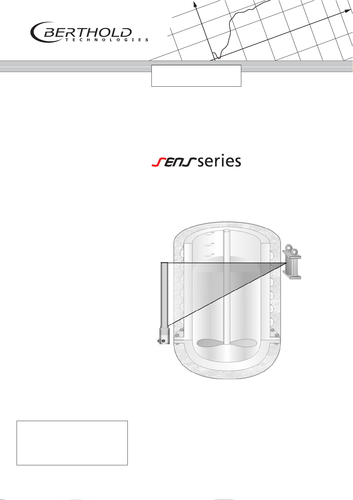
SENSseries LB 480
LB 480
Level measurement
User’s Manual
Id. No. 54733-10BA2L
Rev. No.: 03 02.2017
Embedded Soft. from Rev. 1.00.00
Device Description from Rev. 01
Page 2

Page 3
Volume 1: Safety Manual
1
Volume 2: Installing SENSseries
Volume 3: Operation with HART® Communicator
2
3
Page 4

Volume 1-3
General Information
Dear customer Thank you for purchasing the measuring system SENSseries
LB 480 by BERTHOLD TECHNOLOGIES.
The scope of supply also includes this User’s Manual. Keep this
User’s Manual on hand for reference at any time.
Please observe the warnings and safety instructions given in this
User’s Manual to rule out personal injury and property damage.
They are identified by the following symbols: DANGER, WARNING,
CAUTION or IMPORTANT. In Volume 1, "Meaning of Other Symbols
Used in this Documentation" you find an overview of the hazards to
be observed and instructions on how to deal with these hazards.
Please read this User’s Manual prior to installation to get familiar
with the product.
If you do encounter problems despite careful study of the User’s
Manual, please do not hesitate to contact us.
Your BERTHOLD team
1 – 4 02.2017
54733-10BA2L
Page 5

Inhaltsverzeichnis
Volume 1-3 Table of Contents
Volume 1 Safety Manual
1 About this User’s Manual..................................................1 – 13
1.1 Typographical Conventions....................................... 1 – 13
1.2 Meaning of Other Symbols Used in this
Documentation ........................................................1 – 14
1.3 Meaning of Warning Signs on Detectors and
Source Shieldings .....................................................1 – 14
1.4 Terms Used in this User’s Manual .............................1 – 15
1.5 General Information ................................................. 1 – 16
2 Proper Use ........................................................................1 – 17
3 Qualification of Personnel .................................................1 – 19
3.1 Persons with a General Knowledge........................... 1 – 19
3.2 Experts .....................................................................1 – 20
3.3 Authorized Persons.................................................. 1 – 20
4 Transport and Assembly....................................................1 – 21
5 Explosion Protection..........................................................1 – 23
5.1 Declaration of Conformity ........................................1 – 25
5.2 General Information ................................................. 1 – 26
5.3 Improper Use............................................................ 1 – 26
5.4 Safety Instructions ....................................................1 – 27
5.5 Application Range and Technical Data ...................... 1 – 28
5.6 Installation................................................................ 1 – 34
5.7 Ex – Concept ............................................................1 – 40
5.8 Maintenance and Visual Inspection...........................1 – 49
5.9 ATEX Certificate .......................................................1 – 55
5.10 IECEx Certificate ....................................................... 1 – 65
5.11 FM Certificate........................................................... 1 – 81
SENSseries LB 480 Level measurement
BERTHOLD TECHNOLOGIES GmbH & Co. KG
1 – 5
Page 6

Table of Contents Volume 1-3
6 Electrical Installation .........................................................1 – 87
7 Functional Safety .............................................................. 1 – 91
7.1 Scope.......................................................................1 – 91
7.2 Use...........................................................................1 – 92
7.3 Other Applicable Documents and Records ................1 – 93
7.4 Detector Identification.............................................. 1 – 93
7.5 Project Planning........................................................ 1 – 94
7.6 Device Behavior during Operation........................... 1 – 100
7.7 Installation and Wiring............................................ 1 – 100
7.8 Commissioning.......................................................1 – 101
7.9 Periodic Inspections ................................................ 1 – 102
7.10 Repair.....................................................................1 – 103
7.11 Functional Safety Data Sheet LB 480....................... 1 – 104
7.12 Attachments...........................................................1 – 106
7.13 Functional Safety Certificate ................................... 1 – 108
8 Visual Inspection.............................................................1 – 111
9 Radiation Protection .......................................................1 – 113
9.1 General Information and Guidelines .......................1 – 113
9.2 Mounting the Shielding..........................................1 – 115
9.3 Testing the Shutter Mechanism .............................. 1 – 118
9.4 Safety Measures ..................................................... 1 – 119
9.5 Protection against Theft.......................................... 1 – 119
9.6 Accidents, Loss, Damage, Fire, Theft....................... 1 – 120
9.7 Shielding and Source.............................................. 1 – 122
9.8 Leak Test................................................................1 – 123
10 Source Replacement ....................................................... 1 – 129
10.1 Radiation Exposure during Source Replacement...... 1 – 129
10.2 Point Source Replacement on Rotary
Cylinder Shielding................................................... 1 – 131
10.3 Rod Source Replacement........................................ 1 – 135
10.4 Point Source Replacement on LB 744x Shieldings.... 1 – 140
11 Source Disposal ..............................................................1 – 145
1 – 6 02.2017
54733-10BA2L
Page 7

Volume 1-3 Table of Contents
Volume 2 Installing SENSseries
1 System Description..........................................................2 – 151
1.1 Measuring System ..................................................2 – 151
1.2 SENSseries Hardware .............................................. 2 – 154
1.3 Measuring Principle ................................................2 – 157
1.4 Measuring Arrangements ....................................... 2 – 158
1.5 Technical Data........................................................2 – 162
1.6 Detector Codes ......................................................2 – 166
1.7 Nomenclature of the SENSseries LB 480.................. 2 – 167
2 Installation ......................................................................2 – 171
2.1 Transport to the Installation Site ............................. 2 – 173
2.2 Source Detector Arrangements...............................2 – 175
2.3 Detector Protection ................................................2 – 177
2.4 Detector Assembly.................................................. 2 – 180
2.5 Water Cooling........................................................2 – 187
2.6 Shielding ................................................................2 – 189
3 Electrical Installation........................................................ 2 – 217
3.1 Cable Entries .......................................................... 2 – 217
3.2 Terminals................................................................ 2 – 219
3.3 Connecting the Detector ........................................ 2 – 223
4 Repair, Maintenance and Upkeep ...................................2 – 227
4.1 Safety Instructions ..................................................2 – 228
4.2 Replacing the Complete Detector ........................... 2 – 229
4.3 Replacing the Electronics Module ...........................2 – 231
4.4 Replacing the Crystal-Multiplier Assembly
(for CrystalSENS)..................................................... 2 – 234
4.5 Checking the Detector............................................ 2 – 235
4.6 Customer Service.................................................... 2 – 238
4.7 Repair, Return Shipping .......................................... 2 – 239
5 Technical Information .....................................................2 – 241
5.1 TI LB 480 Level .......................................................2 – 241
5.2 TI LB 480 TowerSENS.............................................. 2 – 276
6 Accessories .....................................................................2 – 289
SENSseries LB 480 Level measurement
BERTHOLD TECHNOLOGIES GmbH & Co. KG
6.1 Cable glands ..........................................................2 – 289
6.2 Limit Switches for Pneumatics................................. 2 – 292
1 – 7
Page 8

Table of Contents Volume 1-3
Volume 3 Operation with
®
HART
Communicator
1 HART
®
Communication .................................................. 3 – 301
1.1 HART® Protocol ..................................................... 3 – 301
1.2 General Information on the
1.3 Connection, Power On and Power Off of the
1.4 Working with the HART
1.5 Archiving Parameter Sets........................................ 3 – 303
HART
HART
®
Communicator ........................................... 3 – 301
®
Communicator ........................................... 3 – 302
®
Communicator ............... 3 – 302
2 Menu Structure ..............................................................3 – 307
2.1 Information on the Menu Structure ........................ 3 – 307
2.2 Menu Overview......................................................3 – 308
2.3 Start Menu.............................................................3 – 313
2.4 Live Display..........................................................3 – 314
2.5 Device Config....................................................... 3 – 316
2.6 Setup .................................................................... 3 – 316
2.7 Quick Start ...........................................................3 – 317
2.8 Quick Start, Step 1................................................. 3 – 317
2.9 Quick Start, Step 2................................................. 3 – 318
2.10 Quick Start, Step 3................................................. 3 – 319
2.11 Sensor Configuration .......................................... 3 – 322
2.12 Date & Time .........................................................3 – 323
2.13 Sensor Settings....................................................3 – 324
2.14 Config Slave Detectors........................................ 3 – 327
2.15 Signal Condition .................................................. 3 – 328
2.16 Signal Parameter ................................................. 3 – 329
2.17 Reading Range..................................................... 3 – 330
2.18 Signal Dependency.............................................. 3 – 331
2.19 Source Exchange..................................................3 – 333
2.20 Cal Parameter.......................................................3 – 335
2.21 Cal Points..............................................................3 – 337
2.22 Cal Settings .......................................................... 3 – 341
2.23 Product Conditions..............................................3 – 343
2.24 Calc Comp Factor ................................................. 3 – 349
2.25 Adapt Calibration ................................................ 3 – 350
2.26 Adjust Lower Point.............................................. 3 – 351
2.27 Adjust Upper Point..............................................3 – 353
1 – 8 02.2017
54733-10BA2L
Page 9

Volume 1-3 Table of Contents
2.28 I/O Setup .............................................................. 3 – 354
2.29 Current Output .................................................... 3 – 355
2.30 Digital Output......................................................3 – 357
2.31 Level Threshold Settings.....................................3 – 359
2.32 Temp. Threshold Settings ...................................3 – 360
2.33 Digital Input ......................................................... 3 – 361
2.34 HART Interface.....................................................3 – 362
2.35 Service ..................................................................3 – 363
2.36 PMT.......................................................................3 – 364
2.37 Sensor Temperature ............................................ 3 – 365
2.38 Test .......................................................................3 – 366
2.39 Test Settings ........................................................3 – 366
2.40 I/O Test Settings ..................................................3 – 369
2.41 Plateau.................................................................. 3 – 370
2.42 Plateau Measurement .........................................3 – 371
2.43 Plateau View ........................................................3 – 372
2.44 Plateau Information ............................................3 – 372
2.45 Meas Parameter...................................................3 – 373
2.46 Meas Data ............................................................3 – 373
2.47 Meas Settings ......................................................3 – 374
2.48 Meas Readings.....................................................3 – 375
2.49 Access ...................................................................3 – 376
2.50 Identification........................................................3 – 378
2.51 Location ................................................................3 – 378
2.52 Device Information..............................................3 – 379
2.53 Device Revision....................................................3 – 380
2.54 Diagnostic ............................................................3 – 381
2.55 Operating Status .................................................3 – 382
2.56 Ext dev status ......................................................3 – 382
2.57 Device Variables Status.......................................3 – 383
2.58 Config Change Status.......................................... 3 – 383
2.59 Lock Device Status...............................................3 – 383
2.60 Error Status .......................................................... 3 – 384
2.61 Log
2.62 Error Log............................................................... 3 – 387
2.63 Modification Log .................................................3 – 388
........................................................................3 – 387
SENSseries LB 480 Level measurement
BERTHOLD TECHNOLOGIES GmbH & Co. KG
3 Getting Started via the HART
3.1 Steps for Getting Started ........................................ 3 – 389
®
Communicator ..............3 – 389
4 Quick Guide to Calibration.............................................. 3 – 391
1 – 9
Page 10

Table of Contents Volume 1-3
5 Calibration...................................................................... 3 – 393
5.1 Preparing Calibration.............................................. 3 – 394
5.2 Calibration with Quick Start.................................... 3 – 396
5.3 Ensuring the Function of the Measurement ............3 – 402
6 Functional Processes ....................................................... 3 – 405
6.1 Multidetector Operation......................................... 3 – 405
6.2 Plateau Measurement............................................. 3 – 406
6.3 Master Reset .......................................................... 3 – 408
7 Explanations ................................................................... 3 – 411
7.1 Background............................................................ 3 – 411
7.2 Conditions for Empty Calibration............................ 3 – 413
7.3 Linear and Exponential ........................................... 3 – 415
7.4 Multi-point calibration............................................ 3 – 417
7.5 Radiation Interference Detection............................. 3 – 420
7.6 Time Constant........................................................ 3 – 423
7.7 Software Versions................................................... 3 – 424
8 Error Handling ................................................................ 3 – 429
8.1 Error Handling Modes.............................................3 – 429
8.2 Device Response to Errors....................................... 3 – 430
8.3 Trouble Shooting.................................................... 3 – 437
8.4 Reset......................................................................3 – 438
8.5 Operation Modes during Measurement .................. 3 – 438
8.6 Error Reset..............................................................3 – 438
8.7 Fault Current..........................................................3 – 439
9 Setup Protocol ................................................................ 3 – 441
1 – 10 02.2017
54733-10BA2L
Page 11

1
g/l
Time
0
00
1
0:30
1
1
:
00
1
1
:
3
0
1
2
:
:
0
0
1
2
:
3
0
Volume 1 Safety Manual
Page 12

Volume 1
1 – 12 02.2017
54733-10BA2L
Page 13
Volume 1 1 About this User’s Manual
IMPORTANT
Tip
1 About this User’s Manual
1.1 Typographical Conventions
The symbols and typefaces used in this User’s Manual have the following meaning:
prompts you to carry out an action.
1, 2, 3, … identifies items in a graphic.
• identifies enumerations.
italic typeface highlights important information.
bold typeface indicates commands or menu items.
bold italic identifies user entries.
The term BERTHOLD TECHNOLOGIES is used in this User’s Manual
for the company BERTHOLD TECHNOLOGIES GmbH & Co. KG.
Please observe the warnings and safety instructions given in this
User’s Manual to rule out personal injury and property damage.
They are identified by the following symbols: DANGER, WARNING,
CAUTION or IMPORTANT.
1
Indicates a direct threat of danger. The consequences will
be death or most severe personal injuries.
Indicates a possibly dangerous situation. If the situation is not
avoided, death or serious bodily injury could result.
Indicates a possibly dangerous situation. If the situation is not
avoided, minor or moderate bodily injury could occur.
Indicates a situation which could result in material damage if the
instructions are not observed.
Paragraphs marked with this symbol provide important information
on the product and on handling the product.
SENSseries LB 480 Level measurement
BERTHOLD TECHNOLOGIES GmbH & Co. KG
Includes application tips and other helpful information.
1 – 13
Page 14
1 About this User’s Manual Volume 1
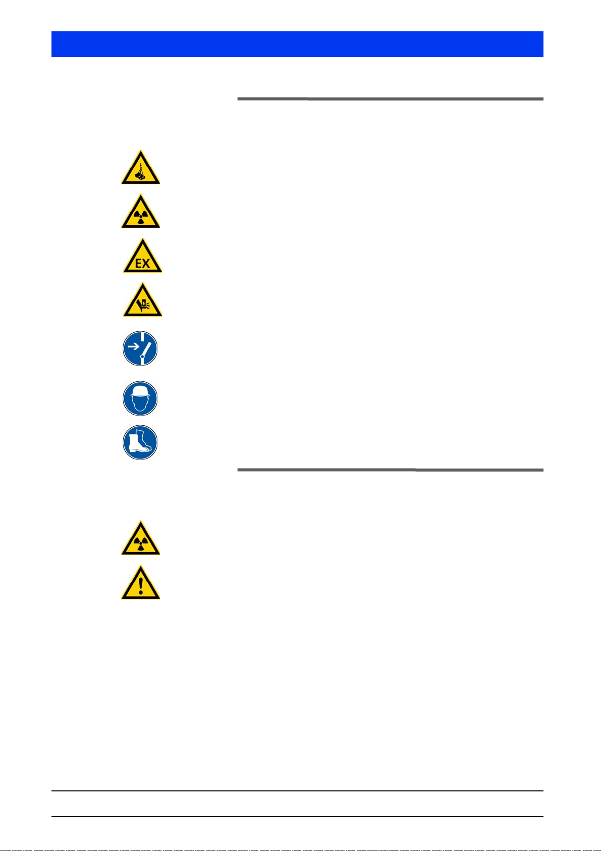
1.2 Meaning of Other Symbols Used in this
Documentation
Warning: Do not step or stand under a suspended load.
Warning: Radiation
Warning: Ex-protection
Warning: Risk of crushing
Requirement: Switch off power
Requirement: Wear a hardhat
Requirement: Wear safety shoes
1.3 Meaning of Warning Signs on Detectors
and Source Shieldings
Warning: Radiation
This warning is located on the source shielding.
Warning: Please read the User’s Manual prior to installation
This warning is located on or in the terminal compartment of the
detector.
1 – 14 02.2017
54733-10BA2L
Page 15

Volume 1 1 About this User’s Manual
1.4 Terms Used in this User’s Manual
CrystalSENS Standard point detector version in the SENSseries LB 480.
UniSENS Standard rod detector version in the SENSseries LB 480.
SuperSENS Highly sensitive detector with large volume polymer scintillator 150
x 150 mm for large pipe or tank diameter.
To we r SE N S Rod detector with an especially large potential measuring length. In
contrast to multi-detector configurations, only one detector is
required here.
NaI detector NaI = sodium iodide crystal = scintillator
Scintillation detectors are very sensitive probes for gamma radiation.
Isotope Substance of the radiation source, e.g. Cobalt 60 (Co-60) or Cesium
137 (Cs-137).
Count rate Value for the number of pulses standardized to one second.
Background The count rate caused by the natural environmental radiation.
Cps Unit for the count rate: Counts per second.
1
Factory setting In the factory setting, all parameters are preset with default values.
In most cases, this makes calibration of the detector a lot easier.
Nevertheless, a calibration must always be carried out.
mSv Milli-Sievert: The unit indicates the dose rate (dose equivalent).
mrem Milli-rem (roentgen equivalent in man): traditional unit for the dose
rate (100 mrem = 1 mSv).
MBq Mega Becquerel: The unit indicates the activity of a source. Each Bq
corresponds to one disintegration per second, i.e. 1 MBq equals one
million disintegrations.
mCi Milli-Curie: Traditional unit for the activity of a source
(1 mCi = 37 MBq).
ATEX Atmosphère explosive: is used as a generic term for the ATEX Prod-
uct Directive 94/9/EC and the ATEX Workplace Directive 1999/92/
EC. The directives contain provisions for equipment and components for use in explosion hazardous areas.
FM Factory Mutual: an American industrial property insurance company
that, among other things, issues certifications in the field of explosion protection.
SENSseries LB 480 Level measurement
BERTHOLD TECHNOLOGIES GmbH & Co. KG
1 – 15
Page 16

1 About this User’s Manual Volume 1
CSA Canadian Standard Association: sets norms and standards that are
important for Canada (and America), among other things, the
Directive for Explosion Protection and Low Voltage.
PMT Photomultiplier or only multiplier: converts the flashes of light gen-
erated by the radiation in the detector into electrical signals.
HV HV = High voltage
The multiplier is operated at high voltage, so that flashes of light
can be converted into electrical pulses.
The high-voltage control allows for measurements that are stable to
temperature and aging. Each multiplier has a slightly different sensitivity, and must therefore be operated at a different high voltage.
active / passive (Source / Sink) Depending on the detector type, the current output can be config-
ured as a current source or current sink. The following terms are
used interchangeably:
• Current source: active / Source Mode
• Current sink: passive / Sink Mode
1.5 General Information
The most important safety measures are summarized in this volume. It supplements the appropriate provisions which the staff in
charge is obliged to follow.
Please pay attention to:
– the national safety and accident prevention regulations
– the national assembly and installation directions (for example,
EN 60079)
– the generally accepted engineering rules
– the information on transport, assembly, operation, service,
maintenance in this User’s Manual
– the safety instructions and information in this User’s Manual
and the enclosed technical drawings and wiring diagrams
– the parameters, limit values and the information on operating
and ambient conditions on the type labels and in the data
sheets
– the labels on the device
Depending on the field of application, the corresponding chapters
have to be taken into account.
1 – 16 02.2017
54733-10BA2L
Page 17

Volume 1 2 Proper Use
2 Proper Use
The measuring system SENSseries LB 480 is a detector which,
depending on its design, can be used for different measurement
tasks:
– Level measurement
– Monitoring limit values
– Density measurement
The measurement system is designed for the continuous monitoring
and detection of levels and limit levels of liquids and bulk solids in
bins, or to determine the density of liquids in tanks and pipes. The
proper use is defined in the project planning stage by BERTHOLD
TECHNOLOGIES, the system delivered may be used only for this
purpose.
If the detector is used in a way which is not provided for during the
project planning stage and which is not described in the User’s Manual, then the detector's protection is compromised and the guarantee claim becomes invalid.
BERTHOLD TECHNOLOGIES only accepts liability for / guarantees
the correspondence of the systems of the SENSseries LB 480 to its
published specifications. The detectors of the SENSseries may only
be installed in an undamaged, dry and clean condition. Alterations
and modifications to the system components are not allowed.
Repairs to the detector may only be made if expressly authorized
by the operating manual.
1
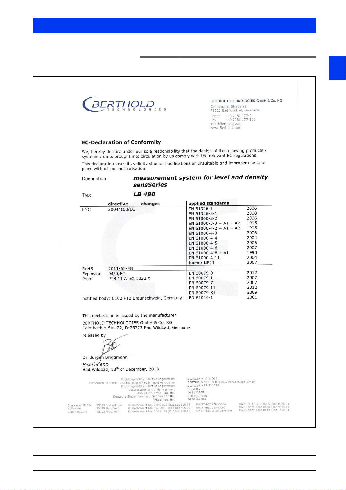
Conformity to standards The standards and guidelines the SENSseries complies with are
itemized in the CE conformity declaration.
SENSseries LB 480 Level measurement
BERTHOLD TECHNOLOGIES GmbH & Co. KG
1 – 17
Page 18

2 Proper Use Volume 1
Warning about misuse The following use is inappropriate and has to be prevented:
– Use under other conditions and prerequisites than those speci-
fied by the manufacturer in his technical documents, data
sheets, operating and assembly instructions and other specifi-
cations.
– The repair of detectors that are used in explosion hazardous
areas by persons who were not authorized by BERTHOLD
TECHNOLOGIES.
– Using the device in a damaged or corroded condition.
– Operation with open or inadequately closed cover.
– Operating with inadequately tightened adapters and cable fit-
tings.
– Operation without the safety precautions provided by the man-
ufacturer.
– Manipulating or bypassing existing safety installations.
Maintenance The measuring system of the SENSseries LB 480 may only be
installed, serviced and repaired by trained persons (see chapter 3.2,
page 1-20).
Repair Spare parts for detectors used in the Ex-area may be assembled
only by the BERTHOLD TECHNOLOGIES service or by persons
authorized by BERTHOLD TECHNOLOGIES. If this is not possible,
you must replace the entire detector or return it to the manufacturer for repair.
Parameter settings Never change the parameter settings without a full knowledge of
this User’s Manual, as well as a full knowledge of the behavior of the
connected controller and the possible influence on the operating
process to be controlled!
Sources and shieldings This measuring system uses radioactive sources. The radiation pro-
tection instructions in this User’s Manual and the relevant statutory
provisions are to be observed strictly, see also chapter 8, "Visual
Inspection", page 1-111.
1 – 18 02.2017
54733-10BA2L
Page 19

Volume 1 3 Qualification of Personnel
IMPORTANT
IMPORTANT
3 Qualification of Personnel
At different parts in this User’s Manual, reference is made to personnel with certain qualifications who can be entrusted with different tasks during the installation, operation and maintenance.
These three groups of people are:
1. Persons with a general knowledge, see chapter 3.1.
2. Experts, see chapter 3.2.
3. Authorized persons, see chapter 3.3.
The following chapters explain the meaning of these terms and the
prerequisites for the particular group of people.
All work on and with the measurement systems SENSseries LB 480
must be performed by persons having at least a general knowledge; they must always be guided by an expert or an authorized
person.
1
3.1 Persons with a General Knowledge
Persons with a general knowledge are e.g. technicians or welders
who can undertake different tasks during the transportation,
assembly and installation of the measuring systems SENSseries
LB 480 under the guidance of an authorized person. This can also
refer to construction site personnel. The persons in question must
have experience in the transportation and assembly of heavy component parts.
Persons working with Ex devices must in addition have knowledge
on how to work with these devices, for example, that the devices
must not be subject to mechanical damage (blow, etc.).
Persons with a general knowledge must always be guided by a
trained expert at the very least.
When dealing with radioactive substances, a Radiation Safety Officer must also be consulted.
SENSseries LB 480 Level measurement
BERTHOLD TECHNOLOGIES GmbH & Co. KG
1 – 19
Page 20

3 Qualification of Personnel Volume 1
3.2 Experts
Experts are persons who have sufficient knowledge in the required
area due to their specialist training and who are familiar with the
relevant national health and safety regulations, accident prevention
regulations, guidelines and recognized technical rules. Expert personnel must be capable of safely assessing the results of their work
and they must be familiar with the content of this User’s Manual.
3.3 Authorized Persons
Authorized persons are those who are either designated for the corresponding task due to legal regulations or those who haven been
authorized by BERTHOLD TECHNOLOGIES for particular tasks.
When dealing with radioactive materials, a Radiation Safety Officer
must also be consulted.
1 – 20 02.2017
54733-10BA2L
Page 21
Volume 1 4 Transport and Assembly
4 Transport and Assembly
The weight of the source shielding may be up to several 100kg,
depending on the version. Please keep in mind:
• The bearing capacity of the vessel walls or the brackets must be
suitable for installation of the source with the shielding and the
detector. Otherwise, system parts may fall off and cause severe
injuries or bodily harm with fatal consequences.
• Make sure that the mechanical stability of the fixing devices
matches the weight of the shielding.
Please keep in mind:
– Never step under hovering loads while unloading heavy system
parts!
– Only use tested lifting equipment matching the transport
weights.
– Maintain adequate safety margin.
– Wear hard hat and safety shoes.
1
– Always ensure good stability for all types of use.
– Make use of the prepared mounting options.
– Work during assembly and installation of heavy and unwieldy
subassemblies should be carried out by at least two people.
– System components must be mounted vibration-free.
– Hold housing cover to prevent falling of housing cover when
opening and closing the terminal compartment.
SENSseries LB 480 Level measurement
BERTHOLD TECHNOLOGIES GmbH & Co. KG
1 – 21
Page 22

4 Transport and Assembly Volume 1
1 – 22 02.2017
54733-10BA2L
Page 23

Volume 1 5 Explosion Protection
Id.-Nr. 54733BA26
Rev. No.: 04 02.2017
5 Explosion Protection
SENSseries
LB 480 - .. 1A
LB 480 - .. 2A
LB 480 - .. 1B
LB 480 - .. 2B
LB 480 - .. 3B
LB 480 - .. 4B
LB 480 - .. FA
LB 480 - .. GA
Safety manual
Explosion Protection
für (Class I) Zone 1 / Zone 21
für Class I, II, III Division 1
ATEX / IECex / NEC / CEC
1
SENSseries LB 480
BERTHOLD TECHNOLOGIES GmbH & Co. KG
1 – 23
Page 24

5 Explosion Protection Volume 1
(bg) Инструкции за безопасност за употреба в
потенциално експлозивни райони. Това
ръководство за безопасност е и на
разположение на официалните езици на
Европейския съюз.
(cs) Bezpečnostní pokyny pro použití v oblastech,
kde hrozí nebezpečí výbuchu. Tato příručka s
bezpečnostními pokyny je k dispozici i v úředních jazycích Evrospké unie.
(da) Skkerhedsvejledning til brug i eksplosions-
farlige omgivelser. Denne sikkerhedsmanual
findes på alle officielle sprog i det Europæiske
fælleskab.
(de) Sicherheitshinweise für den Einsatz in explo-
sionsgefährdeten Bereichen. Dieses Sicherheitshandbuch ist auch in den Amtssprachen der
europäischen Gemeinschaft erhältlich.
(el) Υποδείξεις ασφάλειας για χρήση σε περιοχές με
κίνδυνο έκρηξης. Αυτό το εγχειρίδιο
ασφάλειας διατίθεται επίσης στις
επίσημες
γλώσσες της Ευρωπαϊκής Ένωσης.
(en) Safety instructions for use in potentially explo-
sive areas. This safety manual is available also
in the official languages of the European Community.
(et) Ohutusjuhised kasutamiseks plahvatusoht-
likes piirkondades. Käesolev ohutuskäsiraamat on saadaval ka Euroopa Ühenduse
ametlikes keeltes.
(fi) Räjähdysvaarallisilla alueilla käyttöä koskevat
turvallisuusohjeet. Tämä turvaohjekirja on
saatavilla myös Euroopan yhteisön virallisilla
kielillä.
(fr) Consignes de sécurité relatives à une utilisa-
tion en zones explosives. Le présent manuel
de sécurité est également disponible dans les
langues officielles de la communauté
européenne.
(ga) Treoracha sábháilteachta le haghaidh úsáide i
limistéir inphléasctha Tá an lámhleabhar
sábháilteachta seo ar fáil i dteangacha oifigiúla
an Aontais Eorpaigh, chomh maith.
(hu) Biztonsági utasítások robbanásveszélyes
területeken történő alkalmazáshoz. Ez a biztonsági kézikönyv az Európai Közösség hivatalos nyelvein is rendelkezésre áll.
(it) Istruzioni per l’impiego in ambienti a rischio di
deflagrazione. Il presente manuale contiene le
disposizioni di sicurezza ed è disponibile in
tutte le lingue ufficiali della comunità europea.
(lt) Saugumo nurodymai naudojimui potencialiai
sprogiose zonose. Šį saugumo vadovą taip pat
galima gauti Europos Bendrijos oficialiomis
kalbomis.
(lv) Drošības noteikumi piemērošanai jomās, kas
saistītas ar sprādzienbīstamību. Šī drošības
noteikumu rokasgrāmata ir pieejama arī citās
Eiropas Kopienas oficiālajās valodās.
(mt) Istruzzjonijiet dwar is-sigurtà li għandhom jin-
tużaw f'żoni potenzjalment splussivi. Dan
il-manwal tas-sigurtà huwa disponibbli wkoll
fl-ilsna uffiċjali kollha tal-Komunità Ewropea.
(nl) Veiligheidsinstructies voor de inzet in gebie-
den met gevaar voor explosies Dit veiligheidshandboek is ook in officiële talen in de
Europese Gemeenschap verkrijgbaar.
(pl) Przepisy bezpieczeństwa dotyczące użytkowa-
nia na obszarach zagro
żonych wybuchem.
Niniejsza instrukcja bezpieczeństwa dostępna
jest również w językach urzędowych Unii
Europejskiej.
(pt) Indicações de Segurança para a utilização em
áreas potencialmente explosivas. Este Guia de
Segurança também está disponível nas línguas oficiais da Comunidade Europeia.
(ro) Instructiuni de siguranţă pentru utilizarea în
zone periculoase. Acest manual de siguranţă
este de asemenea disponibil în limbile oficiale
ale Comunităţii Europene.
(sk) Bezpečnostné pokyny pri použití vo výbušnom
prostredí. Táto bezpečnostná príručka je k dispozícii aj v úradných jazykoch Európskej únie.
(sl) Varnostna navodila za uporabo v eksplozijsko
ogroženih območjih. Ta varnostni priročnik je
na voljo tudi v uradnih jezikih Evropske unije.
(sp) Instrucciones de seguridad para el uso en
áreas explosibles. El presente manual de
seguridad está disponible también en las lenguas oficiales de la Comunidad Europea.
(sv) Säkerhetshänvisningar till användning i
områden som är utsatt för exlposionsfara.
Denna handbok finns även tillgänglig i alla
officiella språk av den europäiska
gemenskapen.
1 – 24 02.2017
54733BA26
Page 25
Volume 1 5 Explosion Protection
5.1 Declaration of Conformity
1
SENSseries LB 480
BERTHOLD TECHNOLOGIES GmbH & Co. KG
1 – 25
Page 26

5 Explosion Protection Volume 1
5.2 General Information
This safety manual provides operating instructions in accordance
with the directive 94/9/EG, the standards mentioned in the declaration of conformity, the National Electrical Code (NEC: ANSI/NFPA
70) and the Canadian Electrical Code (CEC).
National responsible authorities can claim additional requests.
Please observe the instructions given in this safety manual to avoid
personal injury and property damage and to ensure safe operation.
5.3 Improper Use
Warning about misuse The following use is inappropriate and has to be prevented:
• Use under other conditions and prerequisites than those specified by the manufacturer in his technical documents, data
sheets, operating and assembly instructions and other specifications.
• The repair of detectors that are used in explosion hazardous
areas by persons who were not authorized by
BERTHOLD TECHNOLOGIES.
• Using the device in a damaged or corroded condition.
• Operation with open or inadequately closed cover.
• Operation with
– inadequately sealed glands,
– inadequately tightened or damaged screwed fittings, i.e.
cable glands, adapters and sealing plugs.
• Operation without paying attention to the manufacturer's
safety precautions.
• Manipulating or bypassing existing safety installations.
1 – 26 02.2017
54733BA26
Page 27

Volume 1 5 Explosion Protection
5.4 Safety Instructions
5.4.1 Safety Instructions for Assembly and Operat-
ing Personnel
Assembly, installation, commissioning, operation and maintenance
must only be carried out by authorized and trained personnel.
Before assembly/commissioning:
• Read the safety manual
• Read the operating manual
• Provide adequate training for assembly and operating person-
nel
• Ensure that the contents of the safety manual and the operat-
ing manual is fully understood by the relevant personnel.
If you are unclear:
• Contact the manufacturer.
•Repair
Repair Spare parts may solely be assembled by the BERTHOLD
TECHNOLOGIES service or by persons authorized by BERTHOLD
TECHNOLOGIES. If this is not possible, you must replace the entire
detector or return it to the manufacturer for repair.
1
SENSseries LB 480
BERTHOLD TECHNOLOGIES GmbH & Co. KG
1 – 27
Page 28

5 Explosion Protection Volume 1
5.5 Application Range and Technical Data
5.5.1 Ex-protection and temperature limits
Test certificates: PTB 11 ATEX 1032 X
IECEx PTB 12.0038X
CSA 70009819
Protection type: IP66 / IP68 according to IEC 60529
IP69K according to ISO 20653
NEMA Type 4X
Air pressure: 80 kPa (0.8 bar) to 110 kPa (1.1 bar)
Oxygen content of the air,
typically: 21 % (Vi/V)
1 – 28 02.2017
54733BA26
Page 29
Volume 1 5 Explosion Protection
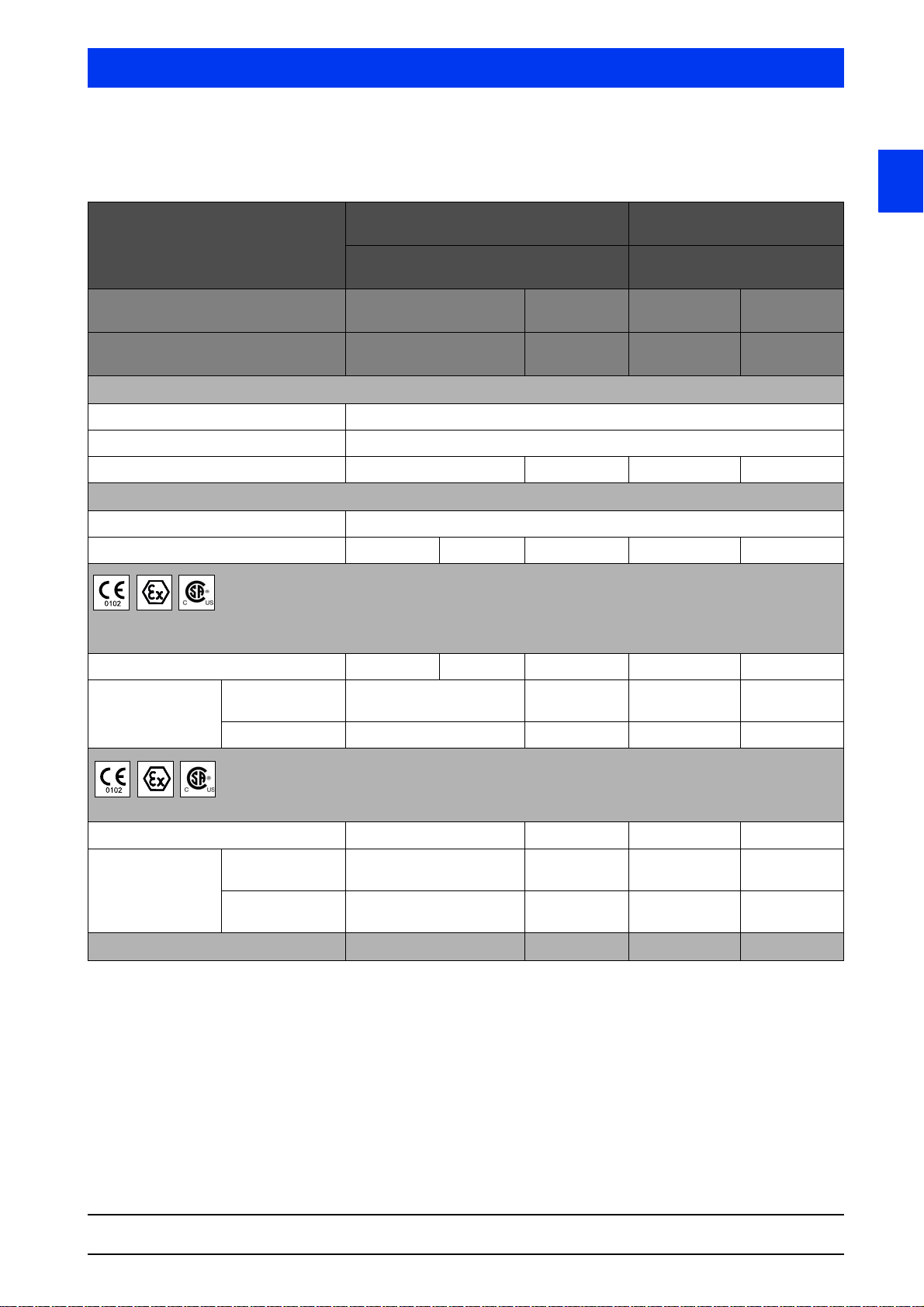
5.5.2 Detector Versions and Application Range for
ATEX/IECEx/NEC/CEC
1
Design LB 480-1x-xx-...
CrystelSENS (point detector))
LB 480-2x-xx-...
UniSENS (rod detector)
Protection concept LB 480-xx-1x
LB 480-xx-2x
Signal circuits not intrinsically safe intrinsically
Ex concept
all rooms Ex-t
Housing (electronics compartment) Ex-d
Terminal compartment Ex-e Ex-e
Ambient temperature
min. T
max. T
Zone 1 + 2, category II 2 G
Class I Zone 1
Temperature class T1-T5 T6 T6 T6 T6
Identification ATEX/IECEx/CEC Ex d e IIC Gb Ex d e [ia Ga]
NEC AEx de IIC AEx de [ia] IIC AEx de IIC AEx de [ia] IIC
≤+80° C Ta≤+65° C Ta≤+50° C Ta≤+65° C Ta≤+50° C
a
LB 480-xx-3B
LB 480-xx-4B
not intrinsically
safe
1)
/Ex-i Ex-e Ex-e1)/Ex-i
≥-40° C
a
Gas
Ex d e IIC Gb Ex d e [ia Ga]
IIC Gb
LB 480-3x-xx-...
SuperSENS
LB 480-4x-xx-...
To we rS E NS
LB 480-xx-1x
LB 480-xx-2x
safe
LB 480-xx-3B
LB 480-xx-4B
intrinsically
IIC Gb
Dust
Zone 21 + 22, category II 2 D
Temperature class T95° C T80° C T80° C T80° C
Identification ATEX/IECEx/CEC Ex tb IIIC Db Ex tb [ia Da]
IIIC Db
NEC AEx tb IIIC AEx tb [ia]
IIIC
Protection principle Ex-d/ -e/ -t Ex-d/ -e/ -i/ -t Ex-d/ -e/ -t Ex-d/ -e/ -i/ -t
1) Internal IP30 protection cover
Ex tb IIIC Db Ex tb [ia Da]
IIIC Db
AEx tb IIIC AEx tb [ia]
IIIC
SENSseries LB 480
BERTHOLD TECHNOLOGIES GmbH & Co. KG
1 – 29
Page 30
5 Explosion Protection Volume 1
FM
CUS
APPROVED
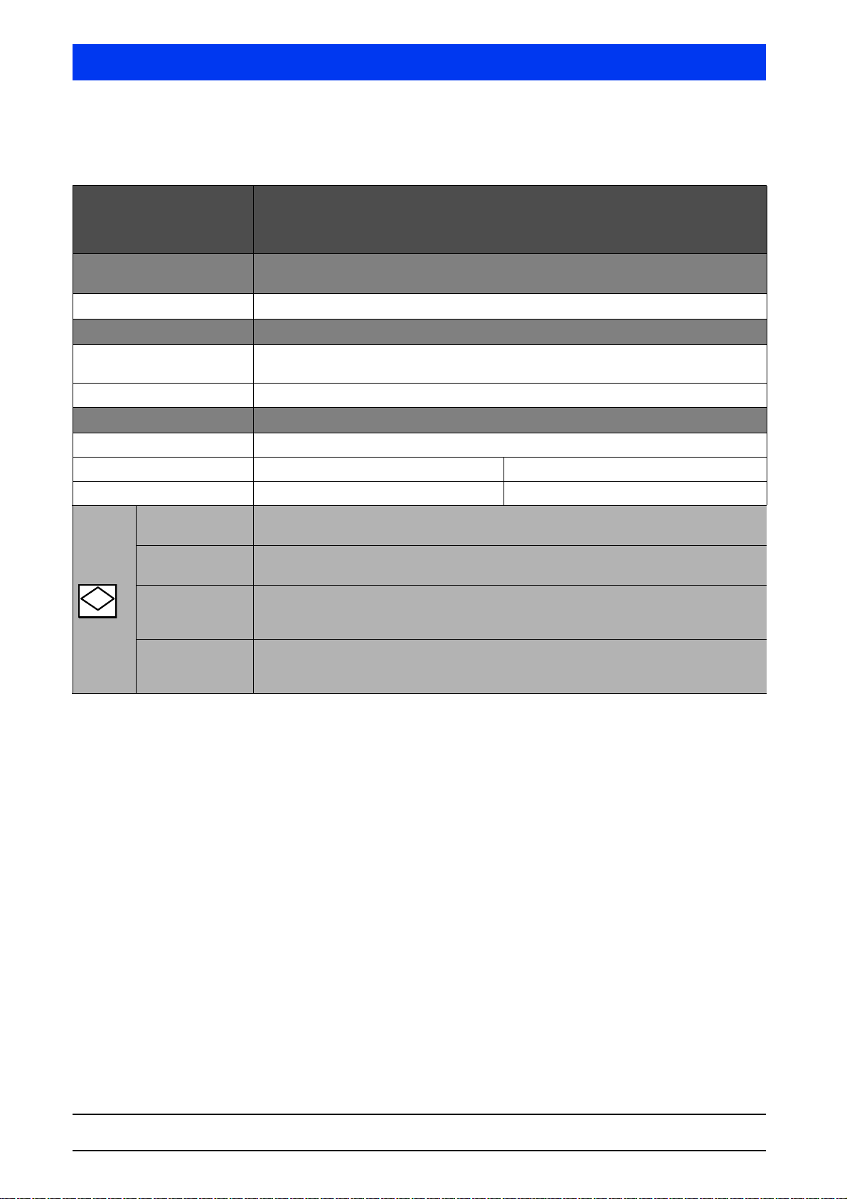
5.5.3 Detector Versions and Application Range for
Divisions according NEC/CEC
Design LB 480-1x-xx-... CrystelSENS (point detector)
LB 480-2x-xx-... CrystelSENS (rod detector)
LB 480-3x-xx-... SuperSENS
LB 480-4x-xx-... PowerSENS
Protection concept LB 480-xx-Fx-...
LB 480-xx-Gx-...
Signal circuit not intrinsically safe
Protection principle
Housing
(electronic compartment)
Terminal compartment explosion proof (XP)
Ambient temperature
min. Ta≥-40° C
explosion proof (XP)
max. T
Temperature class T5 T6
Class I Division 1
US, NEC 500, 501
Class I Division 1
C (Canada) CEC 18
Class II Division 1
US, NEC 500, 502
C (Canada) CEC 18
Class III Division 1
US, NEC 500, 503
C (Canada) CEC 18
≤+80° C Ta≤+60° C
a
Gas
Group A, B, C, D
Gas
Group B, C, D
Dust
Group E, F, G
Fibers
1 – 30 02.2017
54733BA26
Page 31

Volume 1 5 Explosion Protection
5.5.4 Electrical characteristics for supply and RS485
LB 480-xx-xx-x1 LB 480-xx-xx-x2
Supply (terminal 1,2 and 3,4) U = 18 … 32 V
= 250 V
U
m
RS485 circuit
2)
(terminals 5,6) Um = 5 V
2) Only for connection to RS485 interface circuits
other LB 480 detectors
Please note that the maximum permissible ambient temperature at
the detector surface should not be exceeded in case of failure of any
connected water cooling.
Please refer to the technical data of the operating manual for information on the ambient temperature of the water cooling required
so protect the electronics from damage by overheating.
The max. ambient temperature decreases when the detector is not
mounted freestanding; the maximum surface temperature must not
be exceeded.
DC
, 12W
U = 100 … 240 V
DC
Im = 20 mA
, 50/60 Hz, 12 VA
AC
= 250 V
U
m
1
SENSseries LB 480
BERTHOLD TECHNOLOGIES GmbH & Co. KG
1 – 31
Page 32
5 Explosion Protection Volume 1
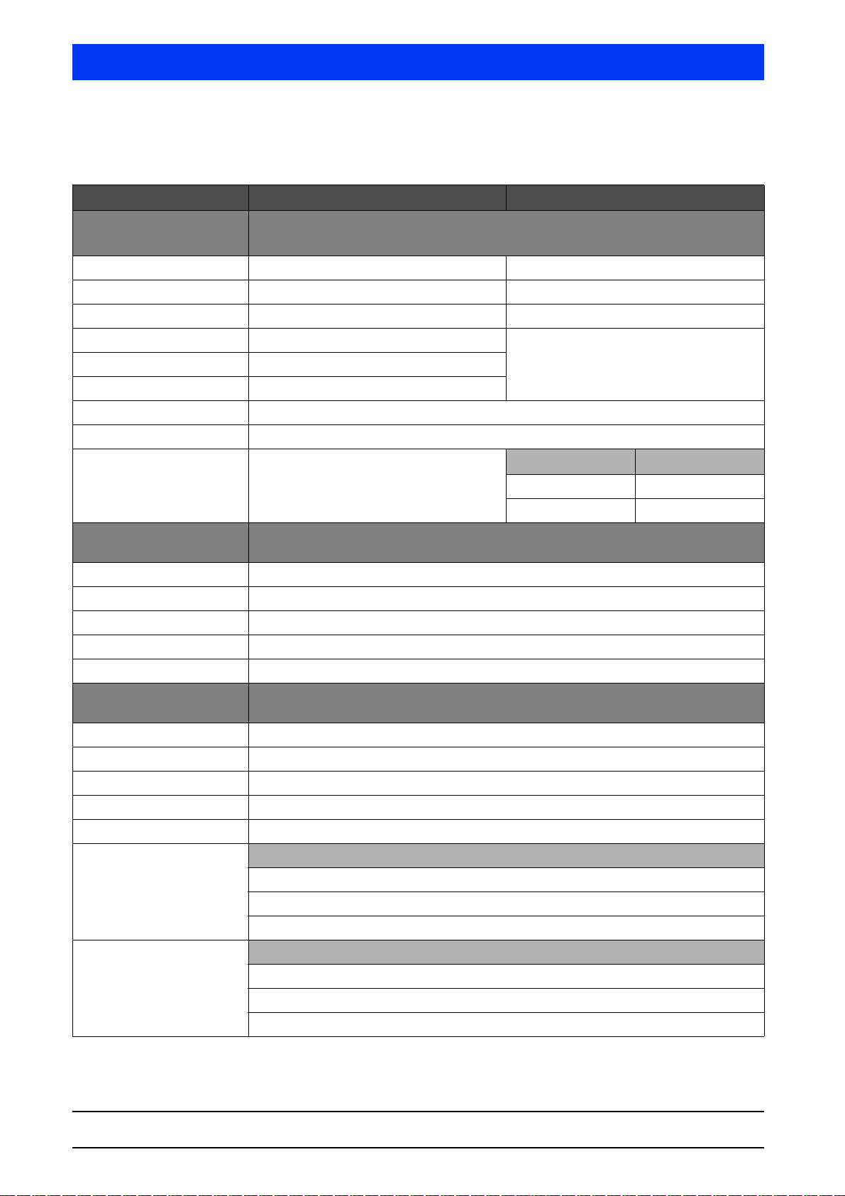
5.5.5 Electrical safety characteristics of the associ-
ated equipment
Signal circuits LB 480-...-3B (Sink) LB 480-...-4B (Source)
Current output
(Terminals 17, 18)
HART® / 4 ... 20mA
linear characteristic curve
max. output voltage U
max. output current I
max. output rating P
max. input voltage U
max. input current I
max. input rating P
max. internal inductance L
max. internal capacitance C
Individual reactances
according to
EN 60079-11, Table A2,
Figure A4 / A6
Signal output
(Terminals 11, 12)
max. input voltage U
max. input current I
max. input rating P
= 30V
i
= 152mA
i
= 1,14W
i
= 20μH
i
= 3nF
i
L
= 17mH Lo = 4mH
o
C
= 0.82μF Co = 0.107μF
o
Open collector circuit
linear characteristic curve
= 15V
i
= 26.6mA
i
= 100mW
i
IIC IIB
max. internal inductance negligibly small
max. internal capacitance C
Signal output
(Terminals 15, 16)
Thermometer circuit (PT100)
linear characteristic curve
max. output voltage U
max. output current I
max. output rating P
= 11nF
i
= 14V
o
= 27,7mA
o
= 97mW
o
max. internal inductance negligibly small
= 25,2V
a
= 101mA
a
= 635mW
a
max. internal capacitance C
Maximum permissible external values jointly acting
reactances (C
into account)
is not taken
i
L
o
L
o
L
o
Maximum permissible external values jointly acting
reactances (C
into account)
is not taken
i
L
= 0.1mH, Co = 0.73μF
o
L
= 0.5mH, Co = 0.71μF
o
L
= 1.0mH, Co = 0.59μF
o
= 11nF
i
IIB
= 0.1mH, Co = 4.6μF
= 0.5mH, Co = 4.0μF
= 1.0mH, Co = 3.3μF
IIC
54733BA26
1 – 32 02.2017
Page 33

Volume 1 5 Explosion Protection
In gas atmospheres, when selecting group IIB or IIC for the intrinsically safe circuits, all intrinsically safe circuits and the LB 480
detector must be operated completely in the selected group IIB or
IIC.
Installation of the probe with protection level "ia" allows the safe
use of measuring instruments that otherwise may be used only in
zone 0 or zone 20.
1
SENSseries LB 480
BERTHOLD TECHNOLOGIES GmbH & Co. KG
1 – 33
Page 34

5 Explosion Protection Volume 1
5.6 Installation
• Observe the installation and safety instructions in the operating
manual.
• Install according to manufacturer's instructions and applicable
standards and regulations.
• Do not operate device outside of the electrical, thermal and
mechanical characteristics.
• Install the housing cover and the screwed fittings (cable glands,
adapters and sealing plugs) correctly to maintain the housing
protection.
• Unused entries must be sealed with metal sealing plugs.
• Please note also the operating and assembly instructions of the
screwed fittings.
• Evidence of intrinsic safety has to be provided prior to the
installation of intrinsically safe circuits (see IEC 60079-14).
The connection of measuring and test equipment must be considered! The installation must be carried out based on this
proof.
• Connect the electrical equipment to the local potential equaliza-
tion.
• With shielded cables, the shielding has to be placed on the
detector side. Observe an adequate insulation >500 V between
the screen and the lines.
• The current output and the open-collector circuit are each float-
ing and have a dielectric strength of at least 500 V
The circuit of the resistance thermometer is electrically connected to the PA port.
For the supply voltage the dielectric strength is at least 1500
.
V
eff
• Use a connection cable that is permitted and suitable for the
application conditions. Observe local regulations!
• The connection cable (conductor and insulation) must be suit-
able for a continuous operating temperature ≥ Ta + 15 K.
• Connected cables must be installed strain-relieved and fixed.
• Do not disassemble the detector housing from the detector
base (see Bild 5-6).
• Use the detectors exclusively for stationary installation.
• Devices that were used in "non Ex-areas" must not be used in
Ex-areas.
• The plan (checklist on page 1-53) for the control of the terminal
compartment has to be completed before commissioning and
every time the terminal compartment has been opened.
eff
.
1 – 34 02.2017
54733BA26
Page 35

Volume 1 5 Explosion Protection
5.6.1 Increased Safety "e" in the Terminal Compart-
ment
Housing Cover • Take the weight (approx. 1.5 kg) of the housing cover into con-
sideration when open and closing it so that it doesn't smash
down.
• Install all four Allen screws (cylinder screws
ISO 4762 M5 x 20 - A4 - 70) for the housing cover with a
torgue of 4 Nm. Use spring washers (DIN 127 - B5 - 1.4310) for
housing covers with flat gaskets. For housing covers with
O-Rings, use Nord-Lock-washers (NL SS).
Screwed fittings • Use only metallic screwed fittings and M20 x 1.5 screwed fit-
tings suitable for the type of protection, depending on their
application, but at least IP65.
• Only screwed fittings are permitted for ambient temperatures
between -20° C and +40° C that technically meet at least the
standard listed on the cover page of LB 480 EC type-examination certificate. Only screwed fittings which have been
approved by BERTHOLD TECHNOLOGIES may be used outside
this temperature range.
• Use only cables and fittings approved in accordance with local
installation regulations. This could require special cables to prevent gas migration and, in particular, fittings with compound
filling.
• Use only screwed fittings that are suitable for the type of cable
(reinforced, non-reinforced, ...) and the cable cross-section.
• When using adapters for thread adjustment (e.g. thread reduc-
tion), only one adapter may be used in each cable gland.
1
• Replace the screwed fittings only by screwed fittings of the
same type.
SENSseries LB 480
BERTHOLD TECHNOLOGIES GmbH & Co. KG
1 – 35
Page 36

5 Explosion Protection Volume 1
Terminals • Permissible wire cross-section:
– with ferrules 0.5 - 1.5 mm2
(AWG 21 - 16 flexible)
– without ferrules 0.5 - 2.5 mm²
(AWG 21 - 14 flexible or solid)
• Both stranded leads as well as solid wires are permitted.
• To connect stranded leads, the following can be used: Ferrules
or direct insertion of the strand into the terminal.
The connection of fine-wire stranded lead class 6, according to
IEC 60228, is only permitted with ferrules.
• Install the connecting cables in the terminal compartment so
that ...
– dirt and moisture is avoided in the terminal compartment;
– the wires are not damaged when stripping.
– the conductor insulation or the collar of the ferrule extends
into the housing of the terminal body;
– bare conductive parts of the lines (e.g. small wires of a
strand) do not protrude from the terminal body;
– the length of the ferrule or the stripped wire must be 10
mm, so that the wire is securely held in the spring-type terminal;
– if ferrules are used, the conductor insulation extends into
the collar of the ferrule;
– clamped conductors and ferrules in the terminals must
comply with a pull-out test according to DIN 46228 for
1 minute:
30 N tensile force for 0.5 mm² cross-section and
50 N tensile force for 2.5 mm² cross-section
The crimped conductors in the ferrules must also pass this
tensile test.
1 – 36 02.2017
54733BA26
Page 37

Volume 1 5 Explosion Protection
5.6.2 Intrinsically Safe Installation Ex "i"
The sections "Screwed fittings" and "Terminals" in chapter 5.6.1
also apply to the intrinsically safe installation.
• The housing cover (metal lid) covers the entire terminal compartment (see Bild 5-3, top).
• Take the weight (approx. 1.5 kg) of the housing cover into consideration when open and closing it so that it doesn't smash
down.
• Install all four Allen screws (cylinder screws
ISO 4762 M5 x 20 - A4 - 70) for the housing cover with a torgue of 4 Nm. Use Nord-Lock-washers (NL SS).
• Seals of the screwed fittings must be designed in such a way
that the separation between intrinsically safe and non-intrinsically safe terminal room is not voided.
• The semicircular plastic cover (Ex-e cover) covers the
non-intrinsically safe terminals (see Bild 5-3, bottom).
• The Ex-e cover must prevent access to non-intrinsically safe
circuits with IP30 protection.
• After installation, the Ex-e cover must completely cover the terminal compartment for the power supply and RS485 interface
again.
• Both screws (flat head screw ISO 7045 - M3 x 8 - 4.8) for fixing
the Ex-e cover must be mounted.
• The housing cover is mounted correctly only if the pin on the
Ex-e cover smoothly clicks into the blind hole of the housing
cover.
• With intrinsically safe versions
– the metal cover to the terminal compartment may be
opened only for a short time for testing and adjustment.
– the semicircular cover in the terminal compartment may be
opened only if the terminal compartment is no longer energized and no explosive atmosphere is present.
• Devices with intrinsically safe circuits must not be connected to
intrinsically safe circuits any more if they have not been used
intrinsically safe before.
1
SENSseries LB 480
BERTHOLD TECHNOLOGIES GmbH & Co. KG
1 – 37
Page 38

5 Explosion Protection Volume 1
5.6.3 Explosion Proof (XP)
The paragraph "Terminals" in chapter 5.6.1 is also valid in this
chapter.
• The threads (cable entries 1/2" NPT and housing cover) must
be protected against damage.
• The threads (cable entries 1/2" NPT and housing cover) must
be protected against moisture and corrosion. Therefore always
lubricate the complete thread with grease OKS 217 in order to
achieve the degree of protection NEMA Type 4X.
Housing Cover • Take the weight (approx. 1.5 kg) of the housing cover into con-
sideration when open and closing it so that it doesn't smash
down.
• Fix the housing cover thoroughly (>10 turns), til the O-Ring is
covered. Tight the housing cover with a torque moment of
25 Nm.
Cable Glands • Ony use metallic cable glands with 1/2" NPT thread.
• Only use cable glands that correlate to the local valid standards
and legal regulations.
• When using conduits, install sealing boxes direct at the cable
entries.
1 – 38 02.2017
54733BA26
Page 39

Volume 1 5 Explosion Protection
5.6.4 Commissioning
•The HART® Communicator used must be capable of operating
within the respective Ex zone.
®
• For intrinsically safe current output, the HART
must also be intrinsically safe. The level of protection (ia, ib, ic)
of the Communicator must be at least the level of protection of
the installed circuit.
Communicator
5.6.5 Protection Principle Ex-d/-e/-t and XP
• Do not open the terminal compartment while voltage is applied.
• If there is an explosive atmosphere:
Waiting time before opening the electronics compartment after
turning off the power supply: 2 minutes.
• Continued operation is not allowed if:
–the detector is damaged
– threads on the housing are corroded
– the detector housing is badly corroded
– dummy plugs are badly corroded or damaged
– cable glands are corroded or damaged
– adapters are badly corroded or damaged
– seals are damaged, show visible aging, or settlement.
1
5.6.6 Protection Principle Ex-d/-e/-i/-t
(intrinsically safe current output)
When opening the terminal compartment during operation, please
keep in mind:
• The housing cover may only be opened for a short time for
repair and maintenance.
• The semicircular cover (Ex cover) must remain closed as long
as the supply voltage is applied.
• Please proceed as described in chapter 5.2.4 if the non-intrinsically safe part of the terminal compartment is to be opened.
Waiting time before opening the Ex-e cover after turning off the
power supply: 2 minutes.
SENSseries LB 480
BERTHOLD TECHNOLOGIES GmbH & Co. KG
1 – 39
Page 40
5 Explosion Protection Volume 1
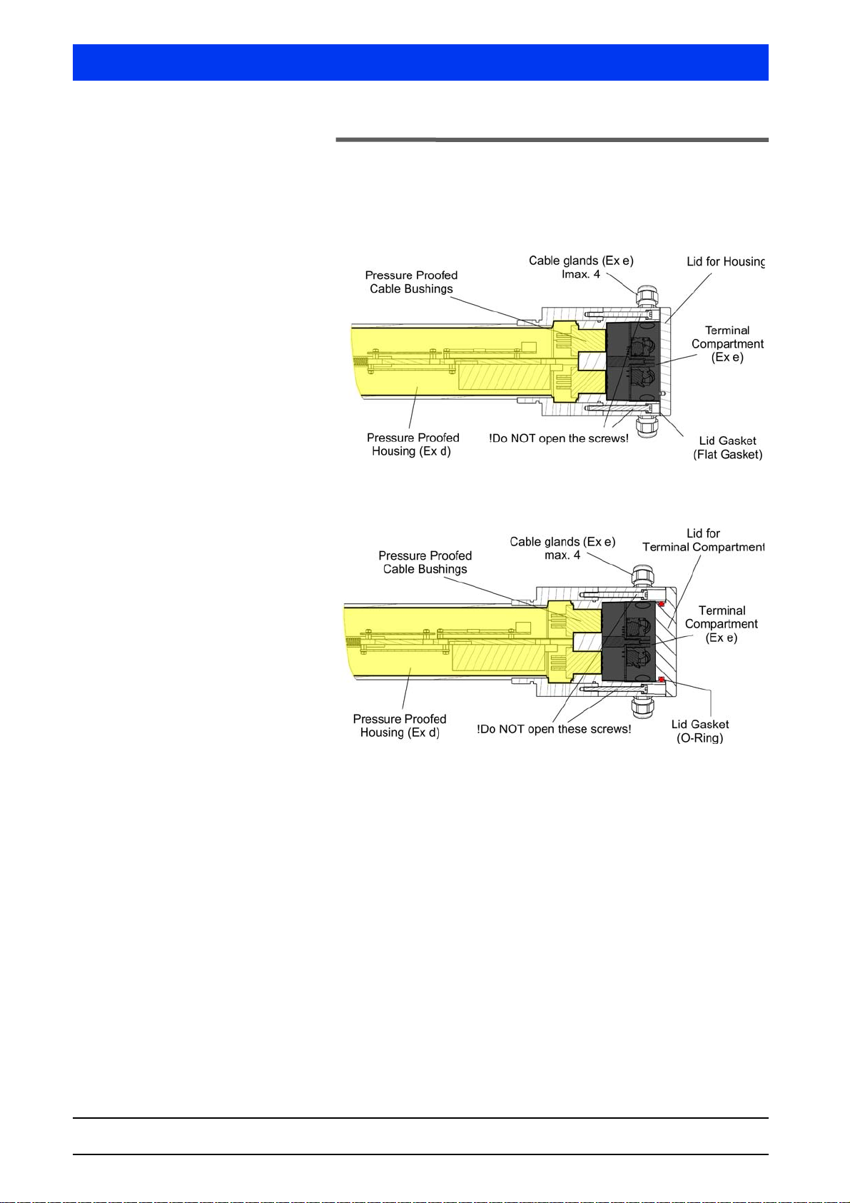
5.7 Ex – Concept
5.7.1 Ex-e – Concept
LB 480-xx-1A
LB 480-xx-2A
LB 480-xx-1B
LB 480-xx-2B
Fig. 5-1 Ex-e - Concept LB 480-xx-1A, LB 480-xx-2A
Fig. 5-2 Ex-e - Concept LB 480-xx-1B, LB 480-xx-2B
1 – 40 02.2017
54733BA26
Page 41
Volume 1 5 Explosion Protection
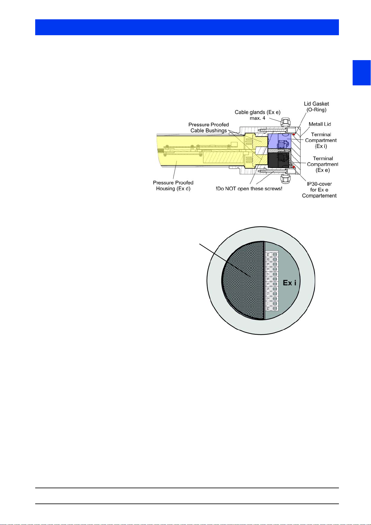
semicircular
cover for Ex-e
compartment with
IP30 protection
type
Master Terminal Compartment
5.7.2 Ex-i – Concept
LB 480-xx-3B
LB 480-xx-4B
The RS485 connection to any connected slave detectors is designed
with increased safety.
1
SENSseries LB 480
BERTHOLD TECHNOLOGIES GmbH & Co. KG
Bild 5-3 Ex-i - Concept LB 480-xx-3B, LB 480-xx-4B
1 – 41
Page 42
5 Explosion Protection Volume 1
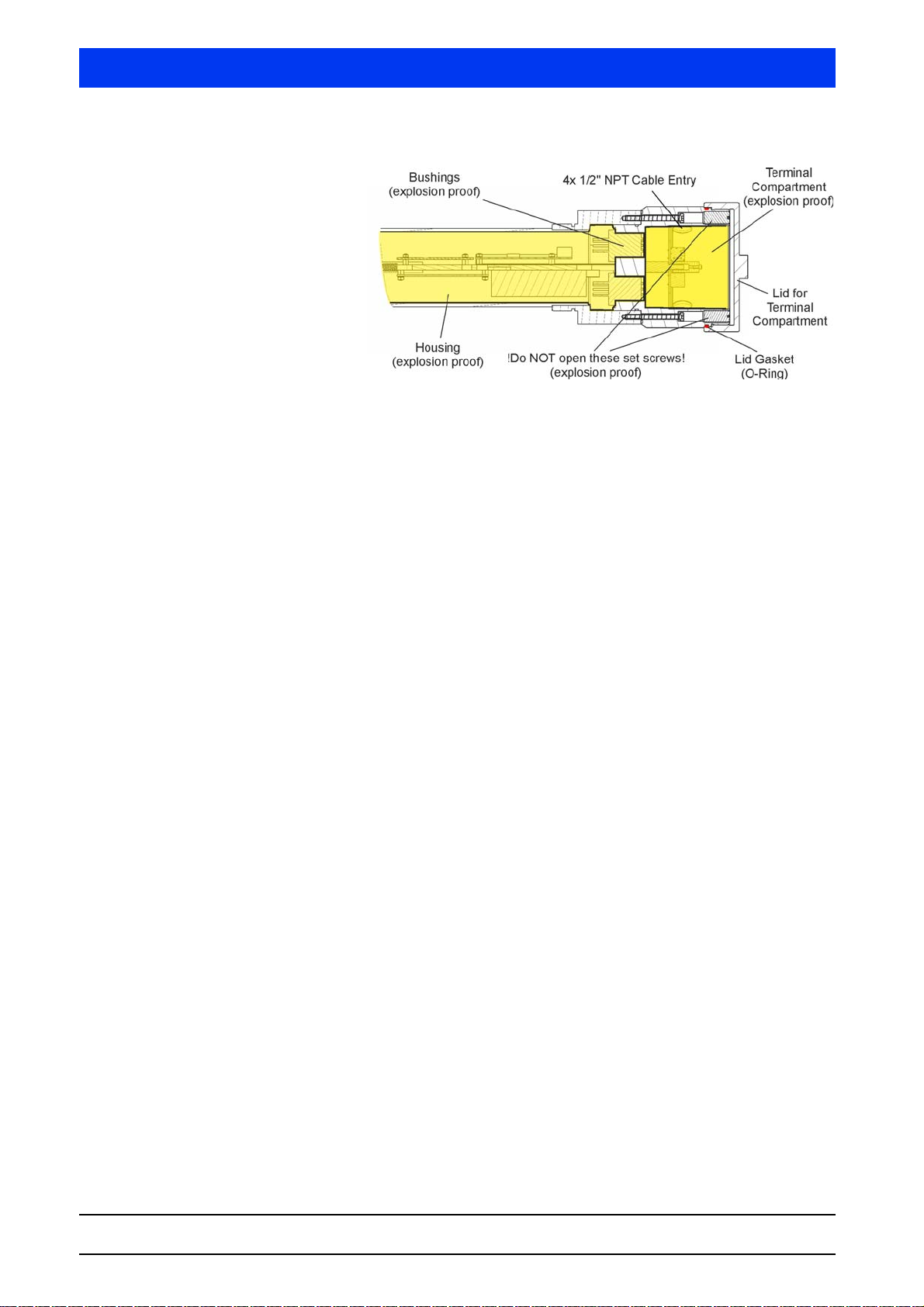
LB 480-xx-FX
LB 480-xx-GX
Fig. 5-4 XP - Concept LB 480-xx-FX, LB 480-xx-GX
1 – 42 02.2017
54733BA26
Page 43
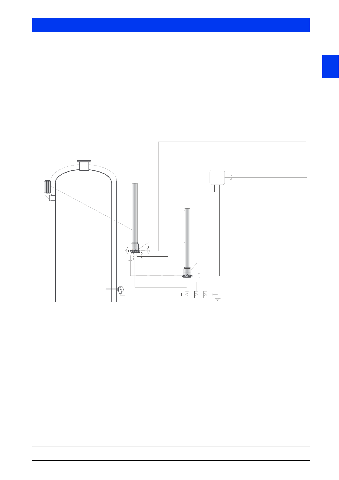
Volume 1 5 Explosion Protection
Equipotential bonding
RS 485 for
Multi Detector Sytsem
Master
Slave
Junction Box
Ex e
Power Supply
Explosion-Hazardous Area
Zone 1, 2
Zone 21, 22
Signal Output
4 ... 20 mA HART, OC
Signal- and Communication Output
100 ... 240 VAC
24 VDC
Zone 0 or Zone 1
Pt100
Terminal Compartment Ex e
Terminal Compartment Ex e
5.7.3 Installation Plan for the Type of Protection
Increased Safety "e" and Intrinsic Safety "i"
Types
LB 480-..-1
LB 480-..-2
LB 480-..-3
LB 480-..-4
1
SENSseries LB 480
BERTHOLD TECHNOLOGIES GmbH & Co. KG
Fig. 5-5 Installation plan type of protection
1 – 43
Page 44
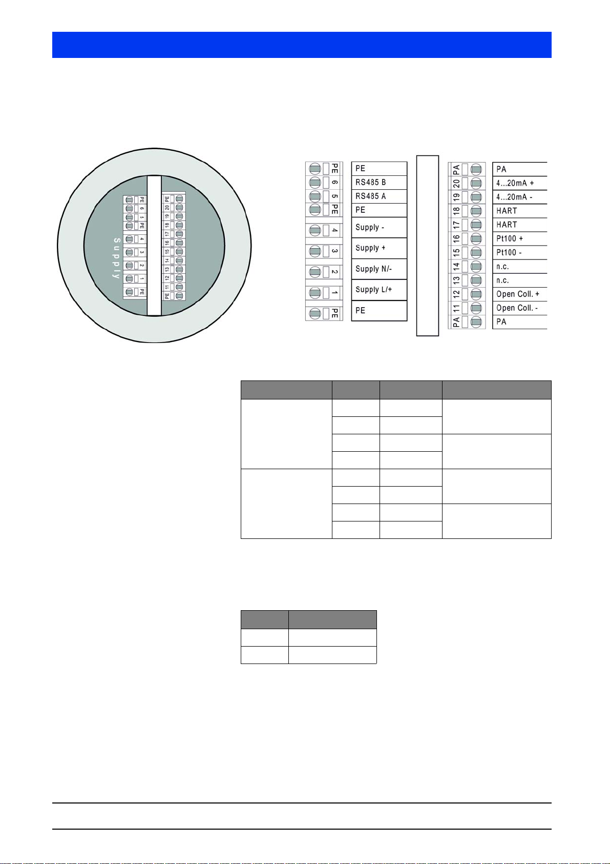
5 Explosion Protection Volume 1
5.7.4 Terminals
5.7.4.1 Terminal Compartment Master Ex-e and XP
Power supply
Te rm in a l Labeling
Type DC supply
LB 480 - .. - .. - 11
Type AC supply
LB 480- .. - .. - 12
Do not connect any wires to the terminals "n.c.", as they are connected to the chassis ground.
Digital interface RS 485
Te rm i na l Labeling
5 RS 485 A
6 RS 485 B
1 Supply + Ue = 24 VDC,
2 Supply -
3 Supply + To forward the supply to
4 Supply -
1 Supply L Ue = 100 ... 240 V
2 Supply N
3 Supply + Do not use to loop
4 Supply -
max. 12 W
the next slave
50/60 Hz, max. 12 V
through the supply!
AC
,
AC
1 – 44 02.2017
54733BA26
Page 45
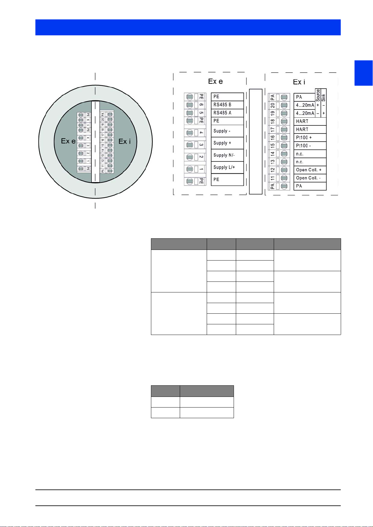
Volume 1 5 Explosion Protection
5.7.4.2 Terminal Compartment Master Ex-e / Ex-i
1
Power Supply
Te rm i na l Labeling
Type DC supply
LB 480 - .. - .. - 11
Type AC sup ply
LB 480- .. - .. - 12
1 Supply + Ue = 24 VDC,
2 Supply -
3 Supply + To forward the supply to
4 Supply -
1 Supply L Ue = 100 ... 240 V
2 Supply N
3 Supply + Do not use to loop
4 Supply -
max. 12 W
the next slave
50/60 Hz, max. 12 V
through the supply!
AC
,
AC
Do not connect any wires to the terminals "n.c.", as they are connected to the chassis ground.
Digital interface RS 485
Te rm i na l Labeling
5 RS 485 A
6 RS 485 B
SENSseries LB 480
BERTHOLD TECHNOLOGIES GmbH & Co. KG
The OC (open collector) and the current output can only be connected to an intrinsically safe repeater. Otherwise, all circuits are no
longer intrinsically safe!
Only a passive component may be connected as Pt100.
1 – 45
Page 46
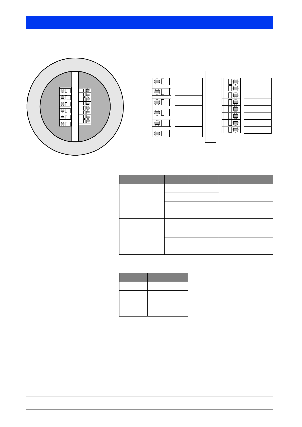
5 Explosion Protection Volume 1
PE
PE
PE1234PE
Supply L/+
Supply N/-
Supply +
Supply -
PE
PE
PE 124PE3
P
5678910PE
E
10
PE89PE 5 6 7
RS 485B In
RS 485A In
TermB
TermA
RS485B Out
RS485A Out
5.7.4.3 Slave Terminal Compartment
Power supply
Te rm in a l Labeling
Type DC supply
LB 480 - .. - .. - 01
1 Supply + Ue = 24 VDC,
2 Supply -
3 Supply + To forward the supply to
4 Supply -
Type AC supply
LB 480 - .. -.. - 02
1 Supply L Ue = 100 ... 240 V
2 Supply N
3 Supply + Do not use to loop
4 Supply -
Digital interface RS 485
Te rm i na l Labeling
5 RS 485 A In
6 RS 485 B In
9 RS 485 A Out
10 RS 485 B Out
max. 12 W
the next slave
50/60 Hz, max. 12 VA
Um = 253 V
AC
AC
through the supply!
,
1 – 46 02.2017
54733BA26
Page 47
Volume 1 5 Explosion Protection
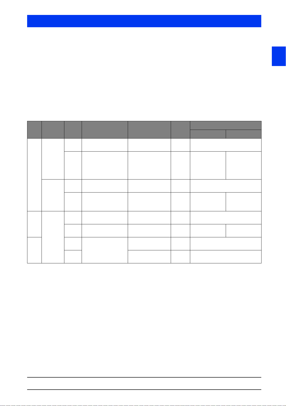
5.7.4.4 Installation Instructions Cable Fittings and
Dummy Plug
The cable glands are used only for the introduction of fixed cables.
Please note the torques, cross sections and protection types of the
screwed fittings in the following table.
The torques specified in the table below are typical values for the
screwed fittings listed in the table, which essentially depend on the
cable used. The pressure screw must be tightened so that the IP
protection is permanently guaranteed.
Cable fittings
1
Ty pe Material ID No. EX labeling / Protection
55412 PTB 11 ATEX 1007 X
IP66 / IP68 / IP69K
59030 IMQ 08 ATEX 021 X
IP66 / IP68
Brass nickel-plated
Standard:
Stainless steel
EMC
Brass nickel-plated
Reinforced
56086 PTB 11 ATEX 1007 X
IP66 / IP68 / IP69K
59033 IMQ 08 ATEX 021 X
IP66 / IP68 / IP69K
56091 PTB 11 ATEX 1007 X
IP66 / IP 68 / IP69K
56092 IMQ 08 ATEX 021 X
IP66 / IP68
56088 PTB 11 ATEX 1007 X
IP66 / IP 68 / IP69K
56103 12 - 20 mm
type
Cable cross-section
for the sealing rings
6-9 mm
9 - 14 mm
4 - 6 mm
6 - 9 mm
9 - 12 mm
6 - 9 mm
9 - 14 mm
4 - 6 mm
6 - 9 mm
9 - 12 mm
9 - 14 mm
(7 - 12 mm screen)
4 - 12 mm
(2 - 10 mm screen)
9 - 14 mm
(9 - 13 mm internal)
(10 - 15 mm internal)
AF Torque / Sealant
Pressure screw Fitting body
24 mm 10 Nm
Silicone
22 mm 12 - 15 Nm
Silicone
24 mm 10 Nm
Silicone
22 mm 12 - 15 Nm
Silicone
24 mm 10 Nm
Silicone
22 mm 12 - 15 Nm
Silicone
24 mm 10 Nm
Silicone
30 mm 10 Nm
Silicone
6 Nm
Neoprene
6 Nm
Neoprene
6 Nm
Neoprene
SENSseries LB 480
BERTHOLD TECHNOLOGIES GmbH & Co. KG
1 – 47
Page 48

5 Explosion Protection Volume 1
Plugs M20 x 1.5
Material ID No. Ex labeling / Protection type AF Torque
56093 PTB 09 ATEX 1002 X
IP66 / IP68 / IP69K
Brass
nickel-plated
Stainless steel
59031 LCIE08 ATEX 6085 X
IP66 / IP68 / IP69K
56094 PTB 09 ATEX 1002 X
IP66 / IP68 / IP69K
59032 LCIE08 ATEX 6085 X
IP66 / IP68 / IP69K
Plugs 1/2" NPT
Material ID No. Ex labeling AF Torque
33910 File: 11716
Class: 4418-03
Brass
nickel-plated
66050 File: 215040
316L
(USA + Kanada)
Class: 2258-02 (Kanada)
Class: 2258-82 (USA)
22 mm 10 Nm
Silicone
23 mm 6 Nm
Neoprene
22 mm 10 Nm
Silicone
23 mm 6 Nm
Neoprene
10 mm 30 Nm
10 mm 30 Nm
Stainless steel
1 – 48 02.2017
54733BA26
Page 49
Volume 1 5 Explosion Protection
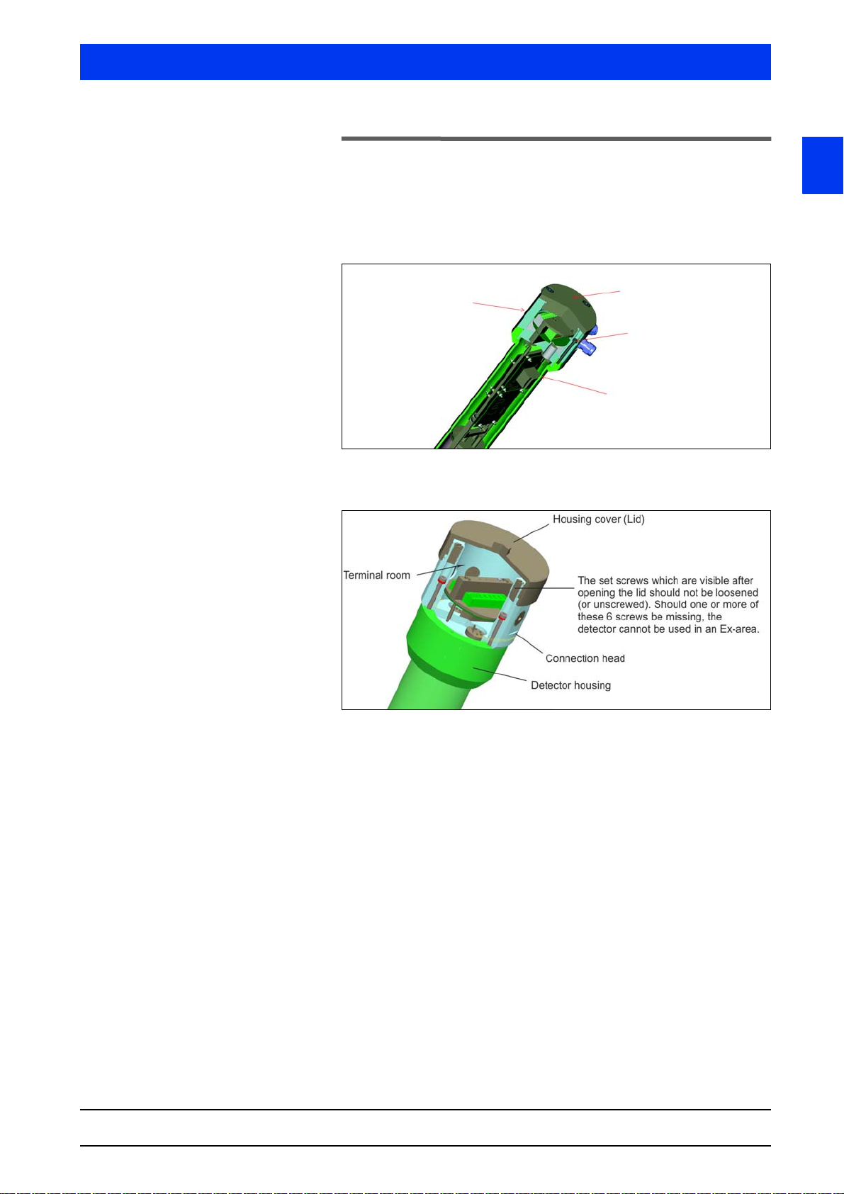
Connection head
Housing cover
The 6 screws connecting
the detector housing with
the connection head
must not be opened.
Detector housing
5.8 Maintenance and Visual Inspection
For detectors that are used in hazardous areas, the detector housing (Bild 5-6) and thus the pressure-proof enclosure of the electron-
ics may be opened only by the BERTHOLD TECHNOLOGIES service
or by persons authorized by BERTHOLD TECHNOLOGIES.
Bild 5-6 Detector housing with connection head with M20 cable entries for
zone classification
1
SENSseries LB 480
BERTHOLD TECHNOLOGIES GmbH & Co. KG
Fig. 5-7 Detector housing with connection head for Class/Divisions with
For commissioning, maintenance or repair, always use the checklists in chapter 5.8.1 and chapter 5.8.2 to document the accuracy
and completeness of your work.
1/2" NPT cable entries
1 – 49
Page 50

5 Explosion Protection Volume 1
Visual inspection Carry out regular visual inspections of the SENSseries measuring
system, at least once every three years. To do this, use the visual
inspection plan in chapter 5.8.1. Take appropriate actions immediately if you detect damage in the course of the visual inspection; if
necessary, disconnect the detector from power supply immediately.
To determine the inspection intervals for the visual inspection, take
the following conditions into consideration:
• ambient conditions (temperature, humidity, corrosive atmosphere, shock and vibrations)
• operating conditions (degree of utilization, operating errors)
• major changes in the overall system (e.g.changes in zoning)
Seals If the cover or the housing is opened, check the respective seals and
replace them, if necessary.
Cleaning Take care not to damage the cable glands and the type plates
during cleaning. Remove coarse debris with a stainless steel wire
brush. Grinding, filing or chipping away deposits with the hammer
is not permitted.
1 – 50 02.2017
54733BA26
Page 51

Volume 1 5 Explosion Protection
5.8.1 Plan for Visual Inspection of the Detector
If you answer one of the following questions with "No", you have to
record the action you have taken to remedy this deficiency in the
last column. Make sure before you take the device into operation
again that the provisions you have taken are correct by consulting
with the person in charge of explosion protection.
Yes No Measures
Date: ...............................................
Name:.................................................
General test
Is the housing free of corrosion, dents,
cracks, holes and warps?
Is the housing cover of the detector firmly
attached?
Are the permissible functional and
safety-related temperatures observed?
Are the external connections of the potential equalizer in good working order?
Is the surface of the detector free of contact
with other non-alloy steel parts?
Are the connected cables installed
strain-relieved?
Is a separator in place?
Is the separator easily accessible for maintenance personnel?
Test of screwed fittings (cable glands, adapters, sealing plugs)
1
Were only metallic fittings used?
Are the screwed fittings suitable for the
ambient conditions?
Are screwed fittings used for the normal
ambient temperature range between -20° C
and +40° C that at least meet the standards specified on the cover page of the EC
type-examination certificate or are screwed
fittings used that have been approved for
use in the LB 480 by BERTHOLD
TECHNOLOGIES?
Is the permissible temperature range of the
screwed fittings suitable for the temperatures encountered?
Are the screwed fittings suitable for the
required protection type (at least IP 65)?
Are the screwed fittings free of corrosion?
SENSseries LB 480
BERTHOLD TECHNOLOGIES GmbH & Co. KG
1 – 51
Page 52

5 Explosion Protection Volume 1
Yes No Measures
Date: ...............................................
Name:.................................................
Test of screwed fittings (cable glands, adapters, sealing plugs), continue
Is more than one adapter (reduction or
extension piece) used?
Is the total length of the cable glands plus
any possibly used adapters less than
10 cm?
Are the cable diameters of the cables used
permitted for the cable glands?
Are the connected cable suitable for the
ambient conditions?
Are the connected cables suitable for a
temperature which is 15° C above the maximum ambient temperature?
Are the screwed fittings undamaged?
Are there any doubts concerning the sealing
of the screwed fittings?
Are the cables firmly clamped in the cable
glands?
Are the screwed fittings firmly tightened?
Are all unused openings provided with
dummy plugs?
Are the dummy plugs adequate for the
required explosion group?
Applies only to detectors with XP protection (Explosion proof)
Is the detector cover thoroughly screwed in
and is the O-ring thoroughly covered?
Are sealing boxes at the cable entries on
the housing available and are they in suitable condition?
1 – 52 02.2017
54733BA26
Page 53

Volume 1 5 Explosion Protection
5.8.2 Plan for Inspection of the Terminal Compart-
ment
If you answer one of the following questions with "No", you have to
record the action you have taken to remedy this deficiency in the
last column. Make sure before you take the device into operation
again that the provisions you have taken are correct by consulting
with the person in charge of explosion protection.
1
Date: ...............................................
Name:.................................................
Test in the terminal compartment
Is the interior (terminal compartment) in
perfect order?
Is the interior dry, clean and free of foreign
material?
Are the cables connected firmly?
Are the terminals in perfect order?
Is the interior free of corrosion?
Is the insulation free of damages or trails?
Is the mechanical fastening of the fixtures
in good working order?
Is the detector installed according to the
local constructor regulations
(e.g. EN 60079-14)?
Does the cable insulation extend into the
terminal compartment?
Does the wire isolation reach into the sleeve
of the terminals, respectively the sleeve of
the ferrules?
When using ferrules: Does the sleeve of the
ferrule extend into the terminal sleeve?
Are all the wires of a fine-wire strand covered by the terminal and clamped?
Is the grounding conductor properly
installed?
Is the screened cable properly insulated
electrically up to the terminal (e.g. with
shrink tubing)?
Yes No Measures
SENSseries LB 480
BERTHOLD TECHNOLOGIES GmbH & Co. KG
1 – 53
Page 54

5 Explosion Protection Volume 1
Yes No Measures
Date: ...............................................
Name:.................................................
Applies only to detectors with intrinsically safe installation (Ex-i)
Does the semicircular lid cover the terminal
compartment (Ex-e)?
Are the screws for the semicircular lid tightened?
Has it been ensured that no wires are
trapped between the semicircular cover and
the underlying holder?
Have both screws (flat head screw ISO
7045 - M3 x 8 - 4.8) of the semicircular
cover been installed?
Can the pin of the semicircular cover
smoothly click into place during the assembly of the housing cover?
Applies only to detectors with XP protection (Explosion proof)
Are all 6 set screws are screwed in?
Is the thread for the detector cover lubricated with grease OKS 217, in order to avoid
corrosion?
Leak test
Is the sealing inside the screwed fittings
OK?
Is the sealing of the cover in the terminal
compartment undamaged and free of
cracks and settlement?
1 – 54 02.2017
54733BA26
Page 55
Volume 1 5 Explosion Protection
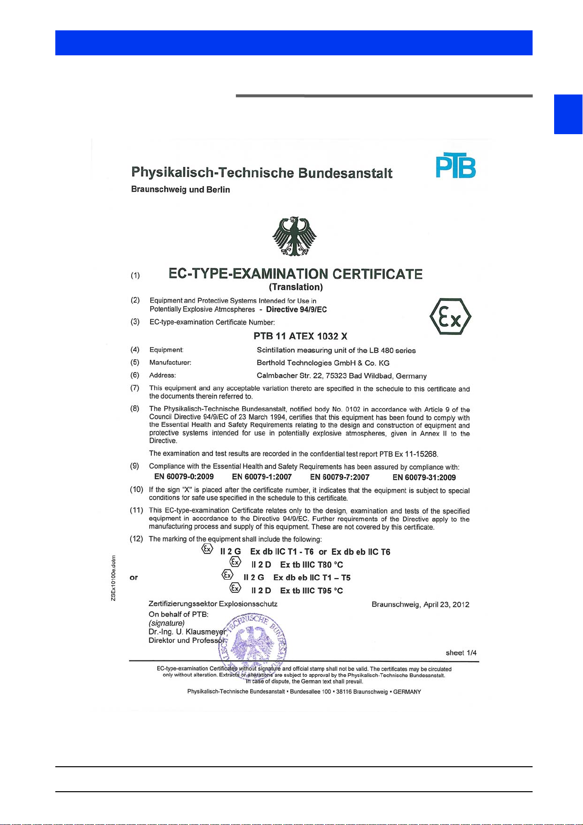
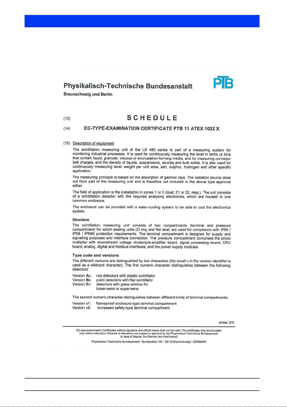
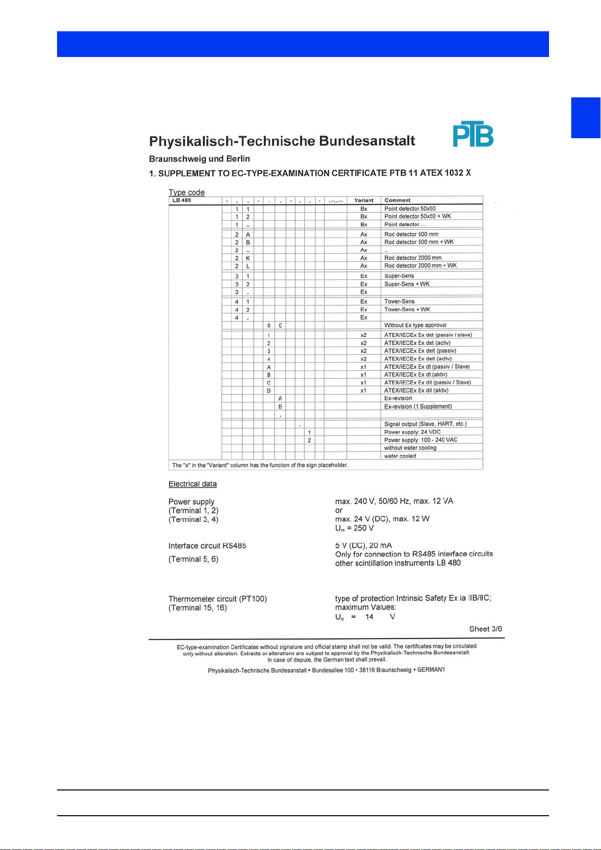
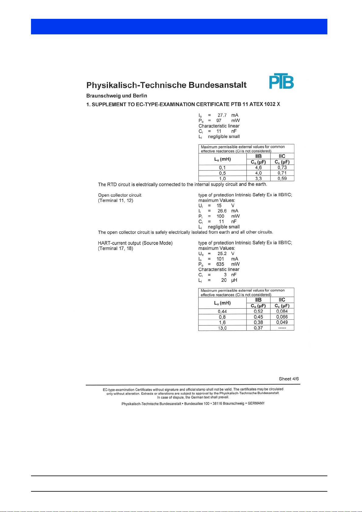
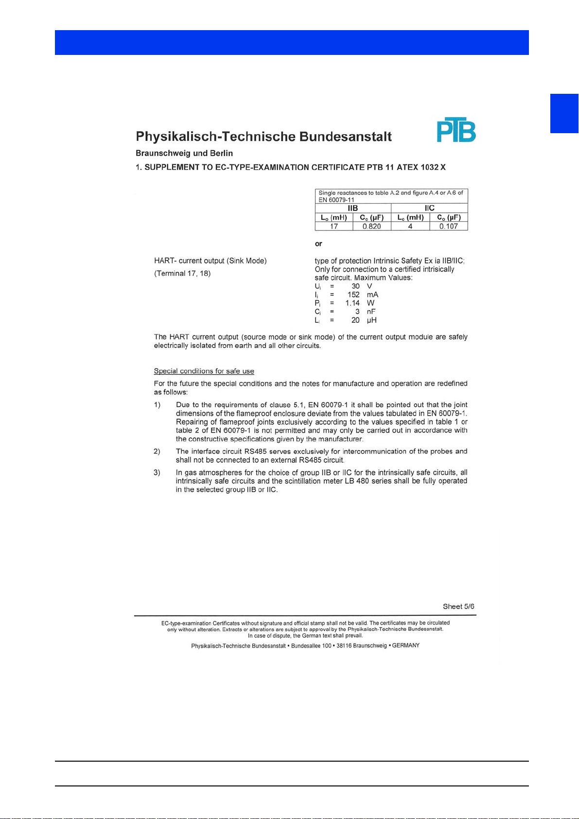
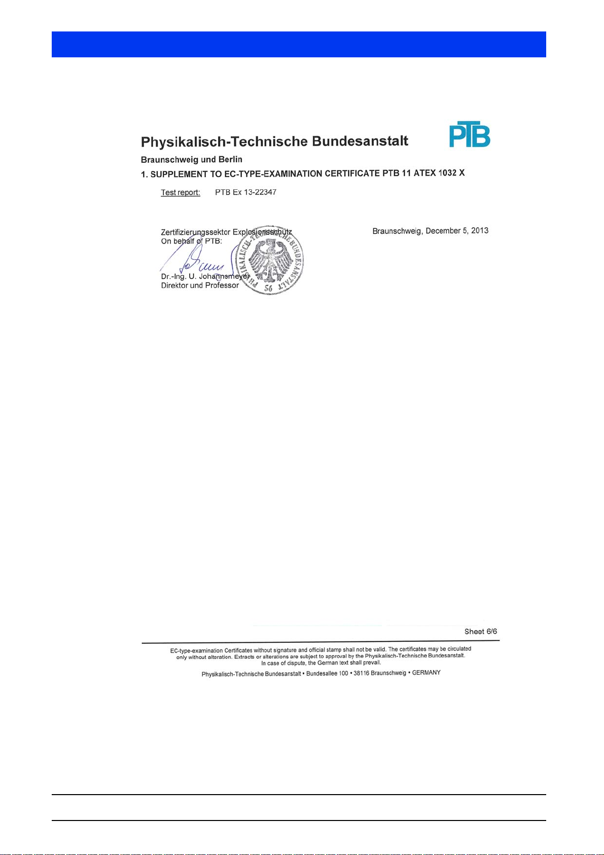
5.9 ATEX Certificate
1
SENSseries LB 480
BERTHOLD TECHNOLOGIES GmbH & Co. KG
1 – 55
Page 56
5 Explosion Protection Volume 1
1 – 56 02.2017
54733BA26
Page 57
Volume 1 5 Explosion Protection
1
SENSseries LB 480
BERTHOLD TECHNOLOGIES GmbH & Co. KG
1 – 57
Page 58
5 Explosion Protection Volume 1
1 – 58 02.2017
54733BA26
Page 59
Volume 1 5 Explosion Protection
1
SENSseries LB 480
BERTHOLD TECHNOLOGIES GmbH & Co. KG
1 – 59
Page 60
5 Explosion Protection Volume 1
1 – 60 02.2017
54733BA26
Page 61
Volume 1 5 Explosion Protection
1
SENSseries LB 480
BERTHOLD TECHNOLOGIES GmbH & Co. KG
1 – 61
Page 62
5 Explosion Protection Volume 1
1 – 62 02.2017
54733BA26
Page 63
Volume 1 5 Explosion Protection
1
SENSseries LB 480
BERTHOLD TECHNOLOGIES GmbH & Co. KG
1 – 63
Page 64
5 Explosion Protection Volume 1
1 – 64 02.2017
54733BA26
Page 65
Volume 1 5 Explosion Protection
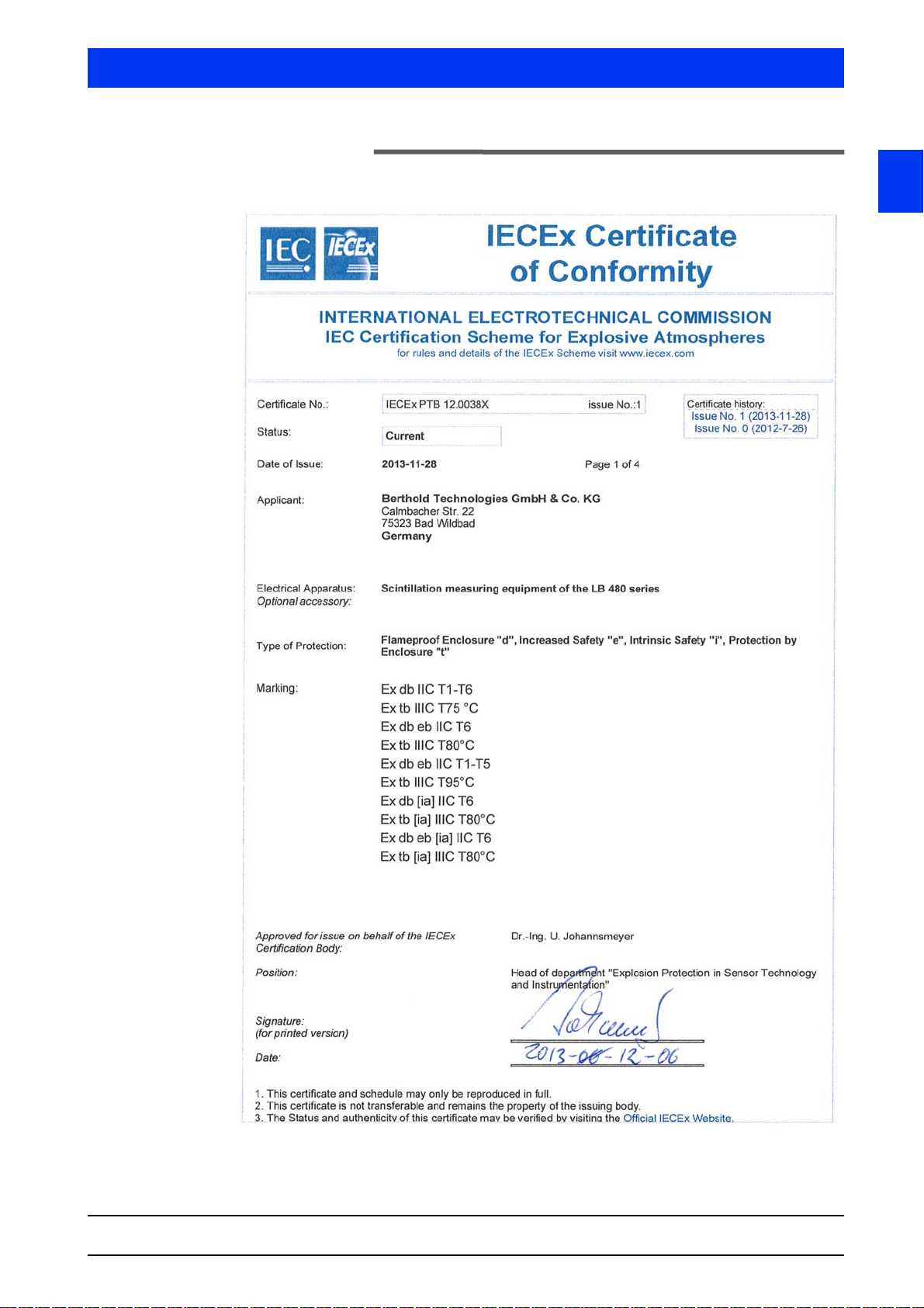
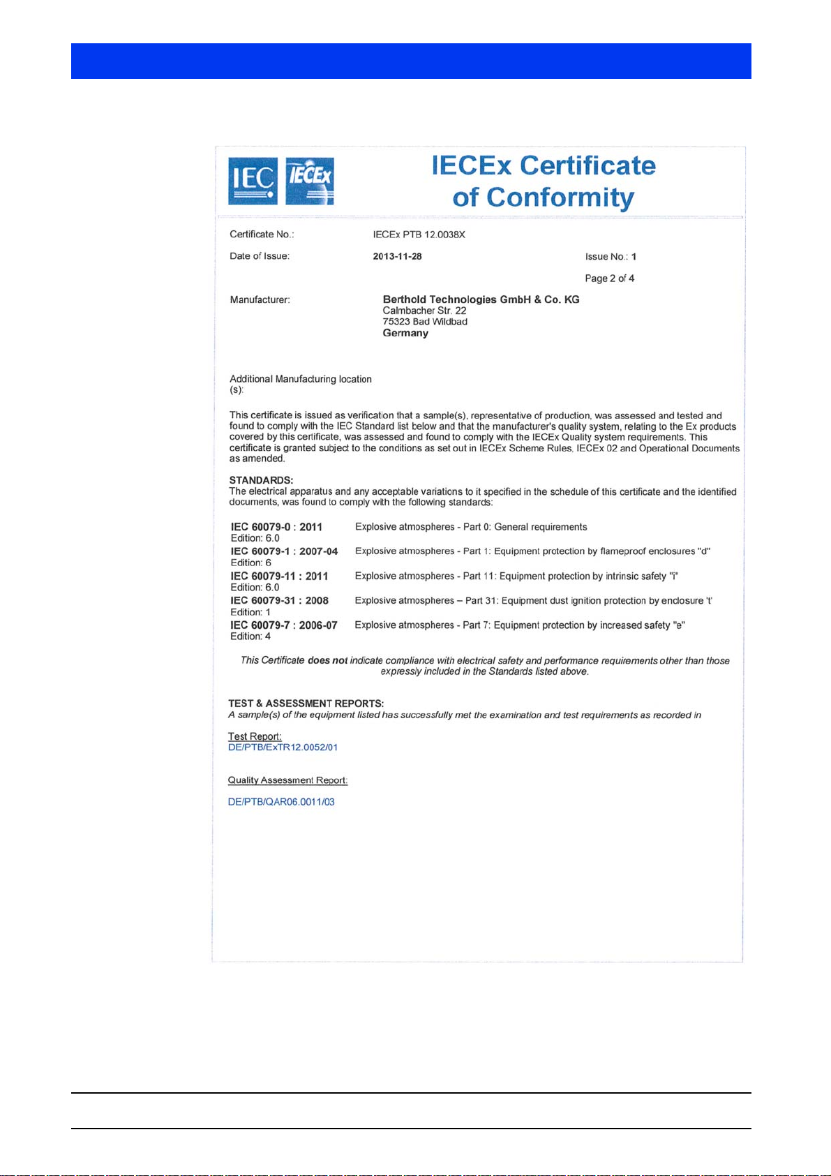
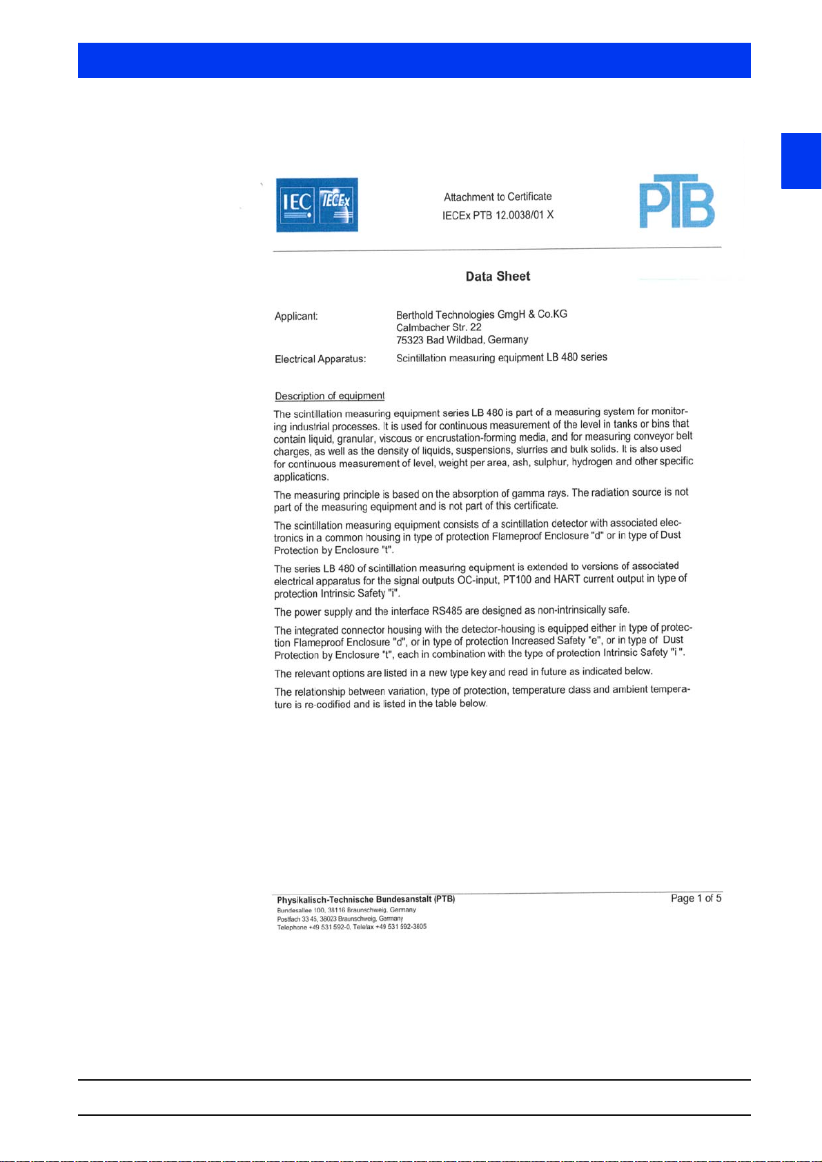
5.10 IECEx Certificate
1
SENSseries LB 480
BERTHOLD TECHNOLOGIES GmbH & Co. KG
1 – 65
Page 66
5 Explosion Protection Volume 1
1 – 66 02.2017
54733BA26
Page 67
Volume 1 5 Explosion Protection
1
SENSseries LB 480
BERTHOLD TECHNOLOGIES GmbH & Co. KG
1 – 67
Page 68

5 Explosion Protection Volume 1
1 – 68 02.2017
54733BA26
Page 69
Volume 1 5 Explosion Protection
1
SENSseries LB 480
BERTHOLD TECHNOLOGIES GmbH & Co. KG
1 – 69
Page 70
5 Explosion Protection Volume 1
1 – 70 02.2017
54733BA26
Page 71
Volume 1 5 Explosion Protection
1
SENSseries LB 480
BERTHOLD TECHNOLOGIES GmbH & Co. KG
1 – 71
Page 72
5 Explosion Protection Volume 1
1 – 72 02.2017
54733BA26
Page 73
Volume 1 5 Explosion Protection
1
SENSseries LB 480
BERTHOLD TECHNOLOGIES GmbH & Co. KG
1 – 73
Page 74
5 Explosion Protection Volume 1
DQD 507 Rev. 2012-05-22 Page 1
Certificate of Compliance
Certificate: 70009819 (215040) Master Contract: 215040
Project: 70066628 Date Issued: 2016-03-07
Issued to: Berthold Technologies GMBH & CO KG
Calmbacher Str 22
Bad Wildbad, 75323
GERMANY
Attention: Juergen Betzelt
The products listed below are eligible to bear the CSA Mark shown
with adjacent indicators 'C' and 'US' for Canada and US or with adjacent
indicator 'US' for US only or without either indicator for Canada only.
Issued by:
David Wood
David Wood
PRODUCTS
CLASS - C225802 - PROCESS CONTROL EQUIPMENT-For Hazardous LocationsCLASS - C225882 - PROCESS CONTROL EQUIPMENT-For Hazardous Locations - Certified to
US Standards
Model LB 480-xx-xx-xx-xx-xxx-x
Variant x1 (Ex-d terminal compartment)
Ex db IIC T1-T6
Ex tb IIIC T75 °C
Ex db [ia] IIC T6
Ex tb [ia] IIIC T80 °C
Zone 1 AEx d IIC T6
Zone 21 AEx tb IIIC T80 °C
Zone 1 AEx d [ia] IIC
T6
Zone 21 AEx tb [ia] IIIC T80 °C
-40 °C ≤ Ta ≤ +60 °C
-40 °C ≤ Ta ≤ +60 °C
-40 °C ≤ Ta ≤ +50 °C
-40 °C ≤ Ta ≤ +50 °C
Variant x2 (Ex-e terminal compartment; rod-, point-detector and detector with cemented glass window)
Ex de IIC T6
Ex tb IIIC T80 °C
Ex de [ia] IIC T6
Ex tb [ia] IIIC T80 °C
Zone 1 AEx de IIC T6
Zone 21 AEx tb IIIC T80 °C
Zone 1 AEx de [ia] IIC
T6
Zone 21 AEx tb [ia] IIIC T80 °C
-40 °C ≤ Ta ≤ +65 °C
-40 °C ≤ Ta ≤ +65 °C
-40 °C ≤ Ta ≤ +50 °C
-40 °C ≤ Ta ≤ +50 °C
Note: The Ex version with the cemented glass window is qualified for temperatures up to
Ta ≤ +70 °C.
1 – 74 02.2017
54733BA26
Page 75
Volume 1 5 Explosion Protection
Certificate:
70009819
Project:
70066628
Master Contract:
215040
Date Issued:
2016-
03-07
DQD 507 Rev. 2012-05-22 Page 2
Variant A2, B2 (Ex-e terminal compartment; rod and point detector)
Ex de IIC T1-T5
Ex tb IIIC T95 °C
Zone 1 AEx de IIC T1-T5
Zone 21 AEx tb IIIC T95 °C
-40 °C ≤ Ta ≤ +80 °C
-40 °C ≤ Ta ≤ +80 °C
Type Code and Versions (variant):
The different versions are distinguished by two characters (the small “x” in the version identifier is used as a
wildcard character). The first numeric character distinguishes between the following detectors:
Version Ax: Rod detectors with plastic scintillator
Version Bx: Rod detectors with Nal scintillator
Version Ex: Detectors with glass window for tower-sens or super-sens
The second numeric character distinguishes between different kinds of terminal compartments.
Version x1: Flame Proof Enclosure type terminal compartment.
Version x2: Increased Safety type terminal compartment.
1
SENSseries LB 480
BERTHOLD TECHNOLOGIES GmbH & Co. KG
1 – 75
Page 76

5 Explosion Protection Volume 1
Certificate:
70009819
Project:
70066628
Master Contract:
215040
Date Issued:
2016-
03-07
DQD 507 Rev. 2012-05-22 Page 3
LB 480
-
.
. - .
. - .
.
-
..-…-.
Version
Description
1 1
Bx
Point Detector 50x50
1 2
Bx
Point Detector 50x50 + Water
1 ..
Bx
Point Detector …
2 A
Ax
Rod Detector 500 mm
2 B
Ax
Rod Detector 500 mm + Water
2 ..
Ax
..
2 K
Ax
Rod Detector 2000 mm
2 L
Ax
Rod Detector 2000 mm + Water
3 1
Ex
Super-Sens
3 2
Ex
Super-Sens + Water Cooling
3 ..
Ex
4 1
Ex
Tower-Sens
4 2
Ex
Tower-Sens + Water Cooling
4 ..
Ex
0 0 Without Ex- Type Approval
1
x2
ATEX/IECEx Ex det (passive /
2
x2
ATEX/IECEx Ex det (active)
3
x2
ATEX/IECEx Ex deit (passive /
Slave)
4
x2
ATEX/IECEx Ex deit (active)
A
x1
ATEX/IECEx Ex dt (passive /
Slave)
B
x1
ATEX/IECEx Ex dt (active)
C
x1
ATEX/IECEx Ex dit (passive /
Slave)
D
x1
ATEX/IECEx Ex dit (active)
A Ex-Revision
..
Ex-Revision
..
Signal Output (Slave, HART, etc.)
1 Power Supply: 24 VDC
2 Power Supply: 100 - 240 VAC
Note: in the LB-480 table description above:
d = flameproof
e = increased safety
i = intrinsic safety
t = dust ignition protection by enclosure
1 – 76 02.2017
54733BA26
Page 77
Volume 1 5 Explosion Protection
Certificate:
70009819
Project:
70066628
Master Contract:
215040
Date Issued:
2016-
03-07
DQD 507 Rev. 2012-05-22 Page 4
Input Ratings:
Variant
Type
Input Rating
Ax, Bx
LB 480-1x-xx-x2
LB 480-2x-xx-x2
100Vac-240Vac, 50/60Hz, 12VA
Ax, Bx
LB 480-1x-xx-x1
LB 480-2x-xx-x1
24Vdc, 12W
Ex
LB 480-3x-xx-x2
LB 480-4x-xx-x2
100Vac-240Vac, 50/60Hz, 12VA
Ex
LB 480-3x-xx-x1
LB 480-4x-xx-x1
24Vdc, 12W
Thermometer Circuit (PT100) Terminals 15 and 16
Type of protection Intrinsic Safety Ex ia IIC Maximum Values:
U
o
= 14.0 V; Io = 27.7 mA; Po = 97.0 mW; Ci = 11 nF; Li = nil
Maximum permissible external values for common effective reactance’s (Ci is not considered)
Lo (mH)
Co (µF)
0.1
0.73
0.5
0.71
1.0
0.59
The RTD circuit is electrically connected to the internal supply circuit and the earth.
Open Collector Circuit (Terminal 11, 12)
Type of protection Intrinsic Safety Ex ia IIC Maximum Values:
U
i
= 15.0 V; Ii = 26.6 mA; Pi = 100.0 mW; Ci = 11 nF; Li = nil
The open collector circuit is safely electrically isolated from earth and all other circuits.
Hart-current output (Source Mode) (Terminal 17, 18)
Type of protection Intrinsic Safety Ex ia IIC Maximum Values:
U
o
= 25.2 V; Io = 101.0 mA; Po = 635.0 mW;
Characteristic Linear: C
i
= 3.0 nF; Li = 20.0 µH
Maximum permissible external values for common effective reactance’s (Ci is not considered)
Lo (mH)
Co (µF)
0.1
0.107
0.5
0.078
1.0
0.061
Single reactance’s to table A.2 and figure A.4 or A.6 of 60079-11
1
SENSseries LB 480
BERTHOLD TECHNOLOGIES GmbH & Co. KG
1 – 77
Page 78
5 Explosion Protection Volume 1
Certificate:
70009819
Project:
70066628
Master Contract:
215040
Date Issued:
2016-
03-07
DQD 507 Rev. 2012-05-22 Page 5
IIB
IIC
Lo (mH)
Co (µF)
Lo (mH)
Co (µF)
17.0
0.820
4.0
0.107
Or
Hart-current output (Sink Mode) (Terminal 17, 18)
Type of protection Intrinsic Safety Ex ia IIC Maximum Values:
U
i
= 30.0 V; Ii = 152.0 mA; Pi = 1.14 W; Ci = 3.0 nF; Li = 20.0 µH
Note: the HART current output (source mode or sink mode) of the current output module are safely electrically
isolated from earth and all other circuits.
Schedule of Limitations:
1) The interface circuit RS485 serves exclusively for intercommunication of the probes and must not be
connected to an external RS485 circuit.
2) In gas atmospheres for the choice of Group IIB or IIC for the intrinsically safe circuits, all intrinsically
safe circuits and the scintillation meter LB 480 series shall be fully operated in the selected Group IIB or
IIC.
APPLICABLE REQUIREMENTS
CSA C22.2 No. 60079-0:2011 - Explosive atmospheres. PART 0: Equipment - General requirements.
CSA C22.2 No. 60079-1:2011 - Explosive atmospheres. PART 1: Equipment protection of flameproof enclosures
“d” Second Edition.
CSA C22.2 No. 60079-7:2012 – Explosive atmospheres. PART 7: Equipment protection by Increased Safety ‘e”
CSA C22.2 No. 60079-11:2014 – Explosive atmospheres. PART 11: Equipment protection by Intrinsic Safety “i”
CSA C22.2 No. 60079-31:2012 - – Explosive atmospheres. PART 31: Equipment dust ignition protection by
enclosure “t”
CSA C22.2 No. 61010-1:12 - Safety Requirements for Electrical Equipment for Measurement, Control, and
Laboratory Use - Part 1: General Requirements
UL 61010-1:2
nd
Edition - Safety Requirements for Electrical Equipment for Measurement, Control, and
Laboratory Use - Part 1: General Requirements
UL 60079-0:2013 - Explosive atmospheres. PART 0: Equipment - General requirements.
UL 60079-1 - 2009 - Explosive atmospheres. PART 1: Equipment protection by flameproof enclosures “d”.
UL 60079-7:2008 – Explosive atmospheres. PART 7: Equipment protection by Increased Safety ‘e”
UL 60079-11:2013 – Explosive atmospheres. PART 11: Equipment protection by Intrinsic Safety “i”
UL 60079-31:2015 - – Explosive atmospheres. PART 31: Equipment dust ignition protection by enclosure “t”
MARKINGS
The manufacturer is required to apply the following markings:
1 – 78 02.2017
54733BA26
Page 79

Volume 1 5 Explosion Protection
Certificate:
70009819
Project:
70066628
Master Contract:
215040
Date Issued:
2016-
03-07
DQD 507 Rev. 2012-05-22 Page 6
x Products shall be marked with the markings specified by the particular product standard.
x Products certified for Canada shall have all Caution and Warning markings in both English and French.
Additional bilingual markings not covered by the product standard(s) may be required by the Authorities Having
Jurisdiction. It is the responsibility of the manufacturer to provide and apply these additional markings, where
applicable, in accordance with the requirements of those authorities.
The products listed are eligible to bear the CSA Mark shown with adjacent indicators 'C' and 'US' for Canada and
US (indicating that products have been manufactured to the requirements of both Canadian and U.S. Standards) or
with adjacent indicator 'US' for US only or without either indicator for Canada only.
Nameplate label material approval information:
(1) Submittor's name, trademark, or the CSA file number (adjacent the CSA Mark).
(2) Catalogue / Model designation.
(3) Complete electrical rating (amps, hertz, and volts).
(4) Serial number traceable to month and year of manufacture.
(5) Hazardous Location Rating
(6) Ambient temperature ranges and applicable Temperature code
(7) Ingress Protection Rating
(9) The CSA Mark with the “c” and “us” qualifiers.
(10) The following bilingual cautions: (as applicable)
Variant
Bilingual cautions
all
“!” symbol: SEE SAFETY MANUAL FOR FURTHER INFORMATION
“!” symbol: IN AN EXPLOSIVE ATMOSPHERE, DE-ENERGIZE AND WAIT 2
MINUTES BEFORE OPENING"
x1
“!” symbol: SEAL WITHIN 50mm OF ENCLOSURE"
1
SENSseries LB 480
BERTHOLD TECHNOLOGIES GmbH & Co. KG
1 – 79
Page 80

5 Explosion Protection Volume 1
DQD 507 Rev. 2012-05-22 Page 1
Supplement to Certificate of Compliance
Certificate: 70009819 (215040) Master Contract: 215040
The products listed, including the latest revision described below,
are eligible to be marked in accordance with the referenced Certificate.
Product Certification History
Project
Date Description
70066628
2016
-03-07
Update to Report 70009819 to include drawing revisions 46032SP #09 and
46031 #08 and correction to entity parameters.
70009819
2015
-11-25
New North American Certification for Scintillation Measuring Equipment,
Model
Series LB 480, for C1Z1, Ex d e [ia] T-Code T1-
T6, and Class II,
Zone 21 based upon IECEx Certification.
1 – 80 02.2017
54733BA26
Page 81

Volume 1 5 Explosion Protection
To verify the availability of the Approved product, please refer to www.approvalguide.com
THIS CERTIFICATE MAY ONLY BE REPRODUCED IN ITS ENTIRETY AND WITHOUT CHANGE
FM Approvals LLC. 1151 Boston-Providence Turnpike, Norwood, MA 02062 USA
T: +1 (1) 781 762 4300 F: +1 (1) 781 762 9375 E-mail: [email protected] www.fmapprovals.com
F 347 (Mar 16) Page 1 of 3
CERTIFICATE OF CONFORMITY
1.
HAZARDOUS (CLASSIFIED) LOCATION ELECTRICAL EQUIPMENT PER US REQUIREMENTS
2.
Certificate No:
FM16US0282X
3.
Equipment:
(Type Reference and Name)
LB 480 Series Scintillation Measurement Equipment
4.
Name of Listing Company:
Berthold Technologies GmbH & Co. KG
5.
Address of Listing Company:
Calmbacher Strasse 22
75323 Bad Wildbad
Germany
6.
The examination and test results are recorded in confidential report number:
3054263 dated 22nd September 2016
7.
FM Approvals LLC, certifies that the equipment described has been found to comply with the following Approval
standards and other documents:
FM Class 3600:2011, FM Class 3615:2006, FM Class 3616:2011,
FM Class 3810:2005, ANSI/NEMA 250:1991
8.
If the sign ‘X’ is placed after the certificate number, it indicates that the equipment is subject to specific
conditions
of use specified in the schedule to this certificate.
9.
This certificate relates to the design, examination and testing of the products specified herein. The FM
A
pprovals surveillance audit program has further determined that the manufacturing
processes and quality
control procedures in place
are satisfactory to manufacture the product as examined,
tested and Approved.
10.
Equipment Ratings:
Explosionproof for Clas
s I, Division 1, Groups A, B, C and D; Dust-
ignitionproof for Class II, Division 1, Groups
E
, F and G; and Class III, Division 1 hazardous (classified) locations, indoors and outdoors (Type 4X
) with an
ambient te
mperature rating of -40°C to +65°C (or +80°C).
Certificate issued by:
22 September 2016
J. E. Marquedant
Manager, Electrical Systems
Date
5.11 FM Certificate
1
SENSseries LB 480
BERTHOLD TECHNOLOGIES GmbH & Co. KG
1 – 81
Page 82
5 Explosion Protection Volume 1
SCHEDULE
US Certificate Of Conformity No: FM16US0282X
THIS CERTIFICATE MAY ONLY BE REPRODUCED IN ITS ENTIRETY AND WITHOUT CHANGE
FM Approvals LLC. 1151 Boston-Providence Turnpike, Norwood, MA 02062 USA
T: +1 (1) 781 762 4300 F: +1 (1) 781 762 9375 E-mail: [email protected] www.fmapprovals.com
F 347 (Mar 16) Page 2 of 3
11.
The marking of the equipment shall include:
Class I Division 1, Groups
A, B, C, D
Class II
, III, Division 1, Groups E, F, G
T6, Ta =
-40°C to +65
T5, Ta =
-40°C to +80°C
Type 4X
12.
Description of Equipment:
General - The LB 480 Series Scintillation Measurement Equipment is used as part of a measuring system for
monitoring industrial processes. The equipment is used for continuously measuring the level or weight per unit
area, in tanks or bins, of liquid, granular, viscous or encrustation
-form
ing media and for measuring conveyor belt
charges as well as the density of liquids, suspensions, slurries and bulk solids. The measurement principle is
based on the absorption of gamma rays. The radiation source is not part of the measuring equipment and is not
included in the product Approval.
Construction
-
The LB 480 Series Scintillation Measurement Equipment consists of a scintillation detector with
associated electronics in an explosionproof/dust
-
ignitionproof enclosure with separate sensor and wiring
compartments. The sensor and wiring compartments are separated by NRTL listed cemented feedthroughs.
The sensor and housing (socket) are constructed of 304 or 316 stainless steel. The wiring compartment
contains four ½
-inch NPT entries and contains
a threaded cover. The socket attaches to the sensor by
cylindrical joint fastened with six bolts. The bolt holes terminate under the threaded cover inside the wiring
compartment) and therefore contain six threaded plugs to form a valid flamepath. The equipment is available
with an optional window which is cemented into the sensor.
Ratings
- The equipment is rated for use in an ambient temperature of -
40°C to +65°C (or +80°C). The
equipment operates at 100
-240 Vac (12 VA) or 24 Vdc (12 W).
LB
480-a-bA-cd-ef-0g0-h. Scintillation Measurement Equipment.
a = Sensor: 11, 12, 13, 14, 15, 16, 2A, 2B
, 2E, 2F, 2I, 2J, 2K, 2L, 31, 32, 41, 42, 43 or 44.
b = Approval: F or G.
c = Signal output: 0 or 1.
d = Power supply: 1 or 2.
e = Collimator: 0, a, r, f or
s.
f = Housing material: 1 or 3.
g = SIL: 0 or S.
h = Software: 0, S, T, U, V, W, L, M, N, O, D, E, F, G, H, J, P or K.
13.
Specific Conditions of Use:
The ambient temperature range and T-code rating for the equipment is as follows:
Ambient Temperature
T-Code
-40°C to +65°C
T6
-40°C to +80°C
T5
1 – 82 02.2017
54733BA26
Page 83
Volume 1 5 Explosion Protection
SCHEDULE
US Certificate Of Conformity No: FM16US0282X
THIS CERTIFICATE MAY ONLY BE REPRODUCED IN ITS ENTIRETY AND WITHOUT CHANGE
FM Approvals LLC. 1151 Boston-Providence Turnpike, Norwood, MA 02062 USA
T: +1 (1) 781 762 4300 F: +1 (1) 781 762 9375 E-mail: [email protected] www.fmapprovals.com
F 347 (Mar 16) Page 3 of 3
14.
Test and Assessment Procedure and Conditions:
This Certificate has been issued in accordance with FM Approvals US Certification Requirements.
15.
Schedule Drawings
A copy of the technical documentation has been kept by FM Approvals.
16.
Certificate History
Details of the supplements to this certificate are described below:
Date Description
22
nd
September 2016
Original Issue.
1
SENSseries LB 480
BERTHOLD TECHNOLOGIES GmbH & Co. KG
1 – 83
Page 84

5 Explosion Protection Volume 1
1.
HAZARDOUS LOCATION ELECTRICAL EQUIPMENT PER CANADIAN REQUIREMENTS
2.
Certificate No:
FM16CA0144X
3.
Equipment:
(Type Reference and Name)
LB 480 Series Scintillation Measurement Equipment
4.
Name of Listing Company:
Berthold Technologies GmbH & Co. KG
5.
Address of Listing Company:
Calmbacher Strasse 22
75323 Bad Wildbad
Germany
6.
The examination and test results are recorded in confidential report number:
7.
FM Approvals LLC, certifies that the equipment described has been found to comply with the following Approval
standards and other documents:
8.
If the sign ‘X’ is placed after the certificate number, it indicates that the equipment is subject to specific
conditions
9.
This certificate relates to the design, examination and testing of the products specified herein. The FM
Approvals surveillance audit program has further determined that the manufacturing
processes and quality
control procedures in place
proved.
10.
Equipment Ratings:
Explosionproof for Class I, Division 1, Groups B, C and D; Dust
ignitionproof for Class II, Division 1, Groups E, F
and G;
Class III, Division 1 hazardous locations, indoors and outdoors (Type 4X) with an ambient
temperatu
Certificate issued by:
22 September 2016
J. E. Marquedant
Manager, Electrical Systems
Date
CERTIFICATE OF CONFORMITY
3054263 dated 22nd September 2016
CAN/CSA-C22.2 No. 0.4:R2013, CSA-C22.2 No. 0.5:2016, CSA-C22.2 No. 25:R2014,
CSA-C22.2 No. 30:R2012, CAN/CSA-C22.2 No. 94:R2011, CAN/CSA-C22.2 No. 61010-1-12:2012
of use specified in the schedule to this certificate.
are satisfactory to manufacture the product as examined, tested and Ap
and
re rating of -40°C to +65°C (or +80°C).
To verify the availability of the Approved product, please refer to www.approvalguide.com
THIS CERTIFICATE MAY ONLY BE REPRODUCED IN ITS ENTIRETY AND WITHOUT CHANGE
FM Approvals LLC. 1151 Boston-Providence Turnpike, Norwood, MA 02062 USA
T: +1 (1) 781 762 4300 F: +1 (1) 781 762 9375 E-mail: [email protected] www.fmapprovals.com
F 348 (Mar 16) Page 1 of 3
-
1 – 84 02.2017
54733BA26
Page 85
Volume 1 5 Explosion Protection
SCHEDULE
Canadian Certificate Of Conformity No: FM16CA0144X
THIS CERTIFICATE MAY ONLY BE REPRODUCED IN ITS ENTIRETY AND WITHOUT CHANGE
FM Approvals LLC. 1151 Boston-Providence Turnpike, Norwood, MA 02062 USA
T: +1 (1) 781 762 4300 F: +1 (1) 781 762 9375 E-mail: [email protected] www.fmapprovals.com
F 348 (Mar 16) Page 2 of 3
11.
The marking of the equipment shall include:
Class I Division 1, Groups B, C, D
Class II, III, Division 1, Groups E, F, G
T6, Ta =
-40°C to +65
T5, Ta =
-40°C to +80°C
Type 4X
12.
Description of Equipment:
General - The LB 480 Series Scintillation Measurement Equipment is used as part of a measuring system for
monitoring industrial processes. The equipment is used for continuously measuring the level or weight per unit
area, in tanks or bins, of liquid, granu
lar, viscous or encrustation-
forming media and for measuring conveyor belt
charges as well as the density of liquids, suspensions, slurries and bulk solids. The measurement principle is
based on the absorption of gamma rays. The radiation source is not part of the measuring equipment and is not
included in the product Approval.
Construction
-
The LB 480 Series Scintillation Measurement Equipment consists of a scintillation detector with
associated electronics in an explosionproof/dust
-ignitionproof enclo
sure with separate sensor and wiring
compartments. The sensor and wiring compartments are separated by NRTL listed cemented feedthroughs.
The sensor and housing (socket) are constructed of 304 or 316 stainless steel. The wiring compartment
contains four
½-
inch NPT entries and contains a threaded cover. The socket attaches to the sensor by
cylindrical joint fastened with six bolts. The bolt holes terminate under the threaded cover inside the wiring
compartment) and therefore contain six threaded plugs to form a valid flamepath. The equipment is available
with an optional window which is cemented into the sensor.
Ratings
- The equipment is rated for use in an ambient temperature of -
40°C to +65°C (or +80°C). The
equipment operates at 100
-240 Vac (12 VA) or 24 Vdc (12 W).
LB
480-a-bA-cd-ef-0g0-h. Scintillation Measurement Equipment.
a = Sensor: 11, 12, 13, 14, 15, 16, 2A, 2B
, 2E, 2F, 2I, 2J, 2K, 2L, 31, 32, 41, 42, 43 or 44.
b = Approval: F or G.
c = Signal output: 0 or 1.
d = Power supply: 1 or
2.
e = Collimator: 0, a, r, f or s.
f = Housing material: 1 or 3.
g = SIL: 0 or S.
h = Software: 0, S, T, U, V, W, L, M, N, O, D, E, F, G, H, J, P or K.
13.
Specific Conditions of Use:
The ambient temperature range and T-code rating for the equipment is as follows:
Ambient Temperature
T-Code
-40°C to +65°C
T6
-40°C to +80°C
T5
1
SENSseries LB 480
BERTHOLD TECHNOLOGIES GmbH & Co. KG
1 – 85
Page 86
5 Explosion Protection Volume 1
14.
Test and Assessment Procedure and Conditions:
This Certificate has been issued in accordance with FM Approvals Canadian Certification Scheme.
15.
Schedule Drawings
A copy of the technical documentation has been kept by FM Approvals.
16.
Certificate History
Details of the supplements to this certificate are described below:
Date Description
22
September 2016
Original Issue.
SCHEDULE
Canadian Certificate Of Conformity No: FM16CA0144X
nd
THIS CERTIFICATE MAY ONLY BE REPRODUCED IN ITS ENTIRETY AND WITHOUT CHANGE
FM Approvals LLC. 1151 Boston-Providence Turnpike, Norwood, MA 02062 USA
T: +1 (1) 781 762 4300 F: +1 (1) 781 762 9375 E-mail: [email protected] www.fmapprovals.com
F 348 (Mar 16) Page 3 of 3
1 – 86 02.2017
54733BA26
Page 87

Volume 1 6 Electrical Installation
6 Electrical Installation
The electrical installation may be carried out only by a qualified
electrician.
Electrical hazards
Risk of fatal injury due to electric shock!
Open the housing only to perform installation, maintenance and
repair work.
When the housing is open, you may come into contact with live
parts if the power supply is connected. During installation and
maintenance work on the hardware of the detector you have to
switch off the measuring system, possibly connected relay contacts, and all the inputs and outputs in order to avoid contact with
live parts.
Never modify the installation without having thoroughly read this
User’s Manual.
1
Cable glands, adapters and
dummy plugs
The screwed fittings must be suitable for the intended use (ATEX or
FM/CSA).
If the detector is not used in explosion hazardous areas, the
screwed fittings, adapters and dummy plugs have to be tested in
accordance with at least one of the following guidelines or standards:
– EN50262
– UL1565
– C22.2 No. 0.17.92
–ATEX
At ambient temperatures of -20 to +40° C, only metallic cable
glands and metal adapters may be used to comply with the protection class IP 65. The material properties of the cable glands, adapters and dummy plugs used must be suitable for the ambient conditions existing at the measuring location.
At ambient temperatures above 40° C and below -20° C, only the
cable glands tested and approved by Berthold may be used.
The tightening torques for the cable glands supplied by BERTHOLD
TECHNOLOGIES are listed on page 1-47.
Please note that only one adapter per cable entry may be used. It
is not permitted to screw together several adapters.
The total length of the cable glands, including any adapter must not
exceed 10 cm.
SENSseries LB 480 Level measurement
BERTHOLD TECHNOLOGIES GmbH & Co. KG
1 – 87
Page 88

6 Electrical Installation Volume 1
IMPORTANT
Cable conduits that are not used must be closed by suitable, metallic dummy plugs.
Special cable glands are required for reinforced cables. The cable
assembly is described in the installation instructions of the cable
conduit used.
In case of doubt, we recommend using screw fittings, dummy plugs
or adapters by BERTHOLD TECHNOLOGIES.
Cables and wires Only use cables with diameters that are permitted for each cable
gland. The cables must have the following wire cross-sections:
–Power cord: 1mm
– Signal lines: 0.5mm2 to 2.5mm
The cables used must be suitable for at least a temperature which
is 15° C above the maximum ambient temperature.
The cables must not be subjected to tensile stress, but have to be
installed strain-relieved. We recommend creating a cable loop in
front of the entry of the housing.
If there is a danger that the cable may be used as a stepladder, then
the cables must be installed protected, for example in conduits. Also
make sure that the cables that are connected to the detector are
laid without abrasion or kinks.
2
to 2.5mm
2
2
Stranded lead The ends of multi-strand wires or fine wire lines (strands) may not
be tinned or soldered. Permitted variations are ferrules and direct
connection of the strand.
When installing fine wire lines in a terminal, individual wires often
get stuck at the edge of the terminal, are then pushed back and in
the worst case project over the insulated edge of the terminal.
Therefore, make sure that all multi-wire or fine wire lines are covered by the terminal and are clamped inside the terminal.
Grounding conductor The grounding conductor has to be connected to the terminals
marked with PE. With interconnected detectors (multi-detector
operation) the PE may not be looped from one detector to another.
Therefore supply lines with PE have to be guided in a star-shaped
pattern from one terminal box to the individual detectors.
Potential equalization Connect the detector to a equipotential busbar on site. The line on
this bar must be as short as possible.
1 – 88 02.2017
54733-10BA2L
Page 89

Volume 1 6 Electrical Installation
IMPORTANT
Separator A separator
– must be present (regulation according to EN 61010-1)
– must be easily accessible for maintenance personnel
– has to be included in the company's internal documentation
It can be installed in the form of a circuit breaker or as a switch and
must meet the requirements of IEC 947-1 and IEC 947-3. If a fuse
is used, it must trigger only at a current of greater than 4 amps per
unit.
General points that are important for installation
Open the terminal compartment in dry ambient conditions, not in
the rain.
Moisture in the terminal compartment can both cause a short circuit with other lines or cancel the explosion protection.
• Please follow the signs on the detectors.
• Connect the cables with special care.
• The connecting cable and its installation must comply with
applicable regulations.
• Make sure when installing the cables that mechanical damage
to the conductor insulation from sharp edges or moving metal
parts will be ruled out. If necessary, install the cable appropriately protected, for example in conduits.
1
• Install the connecting cables in the terminal compartment so
that
– dirt and moisture is avoided in the terminal compartment;
– the wires are not damaged when stripping;
– the conductor insulation or the collar of the ferrule extends
into the housing of the terminal body;
– bare conductive parts of the lines (e.g. small wires of a
strand) do not protrude from the terminal body;
– the length of the ferrule or the stripped wire can be 10 mm,
so that the wire is securely held in the spring-type terminal;
– if ferrules are used, the conductor insulation extends into
the collar of the ferrule;
– the minimum bending radii permitted for the respective
cross-section are not fallen below;
– install the cables strain-relieved and without abrasion.
• The SENSseries detectors may only be operated with fully
closed housing.
• Cleaning corroded threads at the cable glands or cable conduits
using abrasives or a wire brush is not allowed.
SENSseries LB 480 Level measurement
BERTHOLD TECHNOLOGIES GmbH & Co. KG
1 – 89
Page 90

6 Electrical Installation Volume 1
• The use of the detectors is not permitted if:
– cable fittings are corroded or damaged;
– threads on the housing are corroded or damaged;
– dummy plugs are badly corroded or damaged;
– the housing of the detector is badly corroded or damaged;
– seals are damaged, show visible aging, or reduction.
1 – 90 02.2017
54733-10BA2L
Page 91
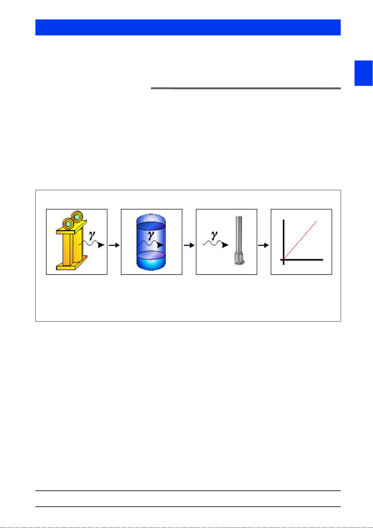
Volume 1 7 Functional Safety
Radiation source Measuring path Measuring device Output
Current output
4-20mA
SENSseries LB 480
Shielded source
- Co-60
- Cs-137
with mechanical
closure mechanism
7 Functional Safety
7.1 Scope
This safety manual applies for radiometric measurement systems
consisting of a radiation source and the measuring system of the
SENSseries LB 480. The measuring system can be used in the following applications:
• Level measurement (also cascaded in a master-slave arrangement)
• Level detection (as max and min limit switches)
• Density measurement
1
SENSseries LB 480 Level measurement
BERTHOLD TECHNOLOGIES GmbH & Co. KG
1 – 91
Page 92

7 Functional Safety Volume 1
7.2 Use
The measuring device LB 480 may only be used as intended. Permissible measuring arrangements as well as the intended use are
described in the operating manual.
For use in safety-related systems (Functional safety according to
IEC 61508:2010 / 61511:2003) all information in this manual has
to be considered.
The measuring device can be operated in the operating mode with
low demand rate (low demand) or with high demand rate (high
demand). For this purpose, the rules according to 7.4.5.3 of IEC
61508-2 regarding the demand rate must be observed specifically
• up to SIL 2 with one detector LB 480
• up to SIL 3 with two detectors LB 480
Any use beyond the information given in this manual shall be
deemed as being not in conformity with the intended use and may
result in serious injury or property damage. BERTHOLD
TECHNOLOGIES GmbH & Co. KG shall not accept any liability for
such injury or damage.
1 – 92 02.2017
54733-10BA2L
Page 93
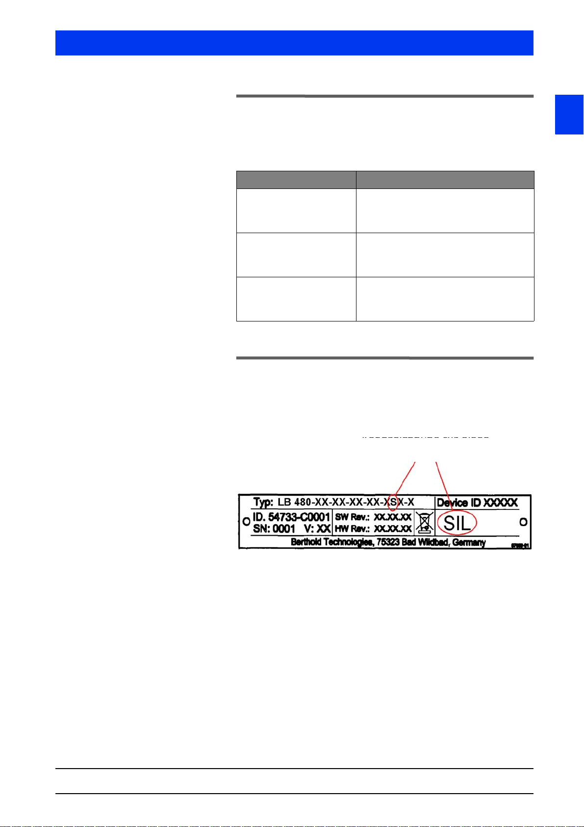
Volume 1 7 Functional Safety
Identification of a
SIL certified detector
7.3 Other Applicable Documents and
Records
Depending on the design of the measuring system, the following
documentation must be observed
Type Operating manual
Level measurement LB 480 Level measurement
ID No. 54733-10BA1L German
ID No. 54733-10BA2L English
Limit level measurement LB 480 Limit level measurement
ID No. 54733-20BA1S German
ID No. 54733-20BA2S English
Density measurement LB 480 Density measurement
ID No. 54733-30BA1D German
ID No. 54733-30BA2D English
The SIL conformity is certified in the attached certificate.
7.4 Detector Identification
SIL-certified detectors are marked on the nameplate with the designation "SIL" and in the LB number key in addition with an "S" (see
figure below).
1
SENSseries LB 480 Level measurement
BERTHOLD TECHNOLOGIES GmbH & Co. KG
1 – 93
Page 94
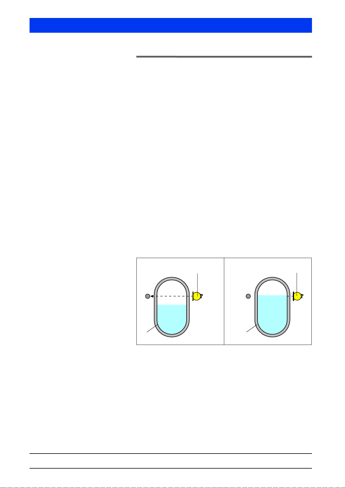
7 Functional Safety Volume 1
Signal
"empty"
Signal
"full"
Shielding with
radiation source
Shielding with
radiation source
Radiation path
Radiation
absorbed by
product
Product
Product
Container
Container
7.5 Project Planning
7.5.1 Safety Function
The measuring system SENSseries LB 480 is used for non-contact
measurement of level, density or concentration. A gamma radiation
source (Co-60 and Cs-137) generates a radiation field which is
attenuated or absorbed by the product to be measured and is
detected by the scintillation detector LB 480.
The following descriptions are exemplary for the respective application. The safety integrity, that is the non-detected measured value
deviation is <2%. If TowerSENS detectors are used the deviation is
<5%. Information on the accuracy of the measurement can be
found in the technical data section of the operating manual.
7.5.1.1 Level detection
The measuring system consists of a detector and a radiation source.
These are mechanically positioned on the filling level and trigger an
alarm once this level is reached. The safety function is to monitor
the fill level of the product to be monitored at a defined fill level.
This can be both an overfill and underfill protection.
Principle of measurement As long as the level is below the beam path, the detector receives
radiation from the radiation source and the signals "Empty". If the
level rises and reaches the height of the beam path, then the radiation is absorbed by the product. The significantly reduced radiation
intensity evaluates the detector signal as a "Full" signal.
The "Empty" signal is displayed on the analog current output with
4 mA, the "Full" signal with 20mA.
54733-10BA2L
1 – 94 02.2017
Page 95
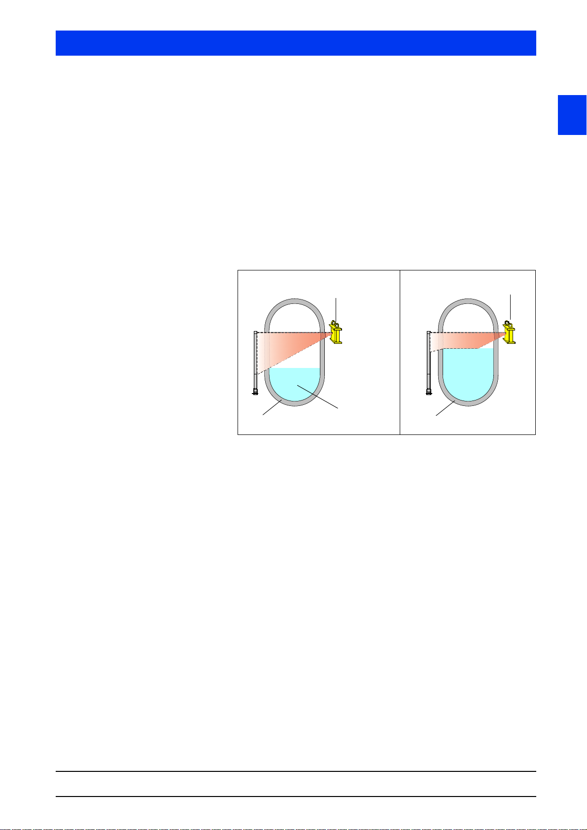
Volume 1 7 Functional Safety
Signal
"0%"
Signal
"70%"
Shielding with
radiation source
Shielding with
radiation source
Radiation path
Radiation in
part
absorbed by
product
Product below
the beam path
Container
Container
Detector
Detector
7.5.1.2 Level measurement
The measuring system consists of a detector and a radiation source.
Both the detector and the radiation source may be designed
rod-shaped or point-shaped. These are mechanically positioned so
that the desired measuring range can be covered. The safety function is to monitor the fill level of the product to be monitored within
the measuring range.
Principle of measurement As long as the level does not reach the area of the beam path, the
radiation arrives unhindered at the detector. Once the level is within
the measuring range, part of the radiation is absorbed. This reduced
radiation intensity is indicated at the detector as rising level. The
more the level rises, the more the radiation is reduced, which the
detector signals as a continuous level increase from 0 to 100%.
1
The level change from 0 ... 100% is represented by the analog current output 4 ... 20mA.
SENSseries LB 480 Level measurement
BERTHOLD TECHNOLOGIES GmbH & Co. KG
1 – 95
Page 96
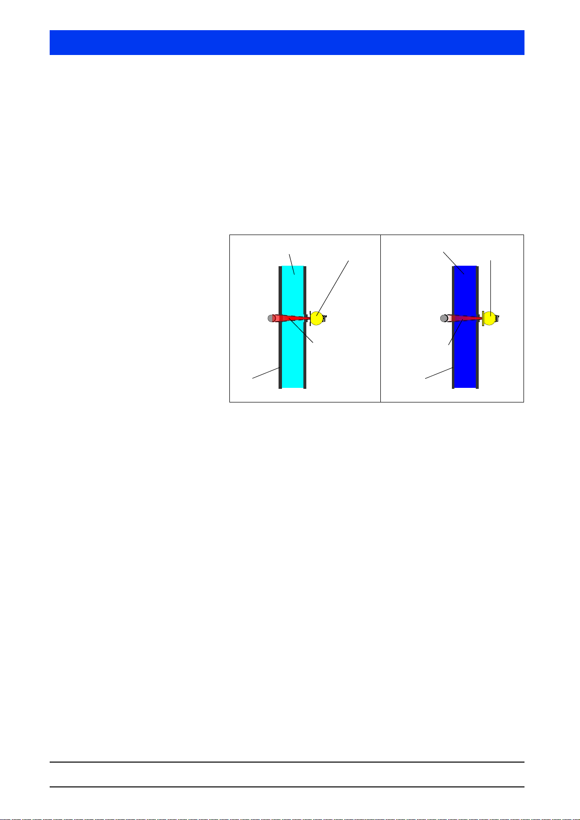
7 Functional Safety Volume 1
Signal
"1.2g/cm
3
"
Shielding with
radiation source
Shielding with
radiation source
Radiation path
Pipeline
Pipeline
Detector
Detector
Signal
"1.0g/cm
3
"
Radiation path
Product density "A"
e.g. 1.0 g/cm
3
Product density "B"
e.g. 1.2 g/cm
3
7.5.1.3 Density measurement
The measuring system consists of a detector and a radiation source.
These are mechanically positioned such that the beam path runs
through the product in order to detect the product density. The
safety function is to monitor the fill level of the product to be monitored within a defined density measuring range.
Principle of measurement A higher product density reduces the radiation intensity at the
detector. A lower product density increases the radiation intensity
at the detector. The change in radiation intensity is output in the
detector as a continuous signal within the measurement range.
The detector signals the change in density via the analog current
signal. The lower measuring range of the density corresponds to
4mA, the upper range corresponds to 20mA. The PT100 may be
used for temperature compensation.
54733-10BA2L
1 – 96 02.2017
Page 97

Volume 1 7 Functional Safety
7.5.2 General Notes and Limitations
• The user-specific limits must be observed and the technical
specifications must not be exceeded. See operating instructions.
• The container geometry on which the source-detector calculation is based must not differ from the one at the mounted measuring point. If there are any deviations, please contact
BERTHOLD TECHNOLOGIES.
• Only the analog 4-20mA current output signal may be used for
safety functions.
• The measuring signal may only be used by the control system
when the Safety Mode is enabled.
• The RS485 interface must be used exclusively for the master-slave communication.
®
•The HART
• If there are magnetic fields in the immediate vicinity of the
measuring point, then you have to make sure through appropriate tests that the magnetic field intensity does not affect the
measuring signal.
• Use only radiation sources with the isotope Co-60 or Cs-137.
• Only shieldings made by Berthold may be used.
• During operation, the source shielding may not be
–closed
– be changed in their position or removed
multidrop mode is not allowed.
1
• It must be prevented that no additional absorber (e.g. steel
plates) get into the beam path, which were not considered for
commissioning.
• Any influence of adjacent radiometric measuring points should
be avoided. If in doubt, the measuring point arrangement has
to be discussed with BERTHOLD TECHNOLOGIES.
• Several detectors may be interconnected into a multi-detector
system. In an interconnection, only one detector may be configured as a master detector.
• In a multi-detector system, the time constant must be
> 2 seconds.
• The user is responsible for the validation of the safety function.
• The following types of detectors can only be used when all
count rates within the measuring range are above 1000 cps.
– LB 480-13 (CrystalSENS 40/35)
– LB 480-14 (CrystalSENS 40/35 with water cooling)
– LB 480-15 (CrystalSENS 25/25)
– LB 480-16 (CrystalSENS 25/25 with water cooling)
These detectors can be operated only with detector code "0".
SENSseries LB 480 Level measurement
BERTHOLD TECHNOLOGIES GmbH & Co. KG
1 – 97
Page 98

7 Functional Safety Volume 1
• Detector code "1" has to be used for the following types of
detectors: when count rates of less than 1000 cps may occur
within the measuring range. In the other case detector code "0"
can be used.
– LB 480-11 (CrystalSENS 50/50)
– LB 480-12 (CrystalSENS 50/50 with water cooling)
• The error current (Loop Alarm Type) has following setup
options:
– High: >21mA
–Low: <3.6mA
7.5.3 Assumptions
The evaluation of the measuring device according to functional
safety aspects is based on the following assumptions:
• The failure rates are constant over the lifetime.
• The environmental conditions correspond to an average industrial environment.
• The repair time (replacement of the measuring system) after
an interference immune error is 72 hours. (MTTR
• The maximum operating time is limited by the average count
rate and the scintillator used:
1
= 72h).
maximum operating time
average count
rate
40000 cps 10 years 10 years
80000 cps 5 years 10 years
CrystalSENS
(Point detectors
with NaI crystal)
UniSENS (rod detectors)
SuperSENS
Towe rSEN S
• A temperature compensation can be used for a density measurement.
The following error cases are not considered:
• Closing or removing the source
• Failure rates of external power supplies
• Multiple errors
1. MTTR = Mean Time To Repair
1 – 98 02.2017
54733-10BA2L
Page 99

Volume 1 7 Functional Safety
7.5.3.1 Determination of the Failure Rates
The failure rates of the device were determined by an FMEDA
according to IEC61508. The calculations are based on component
failure rates according to SN29500. All numerical values refer to an
average ambient temperature during the operating time of 40° C
(104°F). For higher temperatures, the values should be corrected:
• Continuous operating temperature 50 … 60° C (122...140°F)
by a factor of 1.3
• Continuous operating temperature 60 … 70° C (140...158°F)
by a factor of 2.5
• Continuous operating temperature 70 … 80° C (158...176°F)
by a factor of 4.5
Similar factors apply when frequent temperature fluctuations are
expected.
1
SENSseries LB 480 Level measurement
BERTHOLD TECHNOLOGIES GmbH & Co. KG
1 – 99
Page 100

7 Functional Safety Volume 1
7.6 Device Behavior during Operation
7.6.1 Device Behavior after Power On
After power on, a diagnosis phase of 15 seconds starts in which the
measuring device is checked for errors. The current output changes
to 24mA for 2 seconds and then to 0mA. During this time, no communication with the device is possible.
If an error is detected during the diagnosis phase, the device
changes to fault current. In the other case, a current in the range
between 3.8 ... 20.5 mA is output.
7.6.2 Behavior of the Current Output in Case of
Error
If the measuring device detects a fault, the current output is
brought to a safe condition.
Error >21mA or <3.6mA:
There is a hardware or software error.
Please refer to the operating manual for a detailed description of the
error behavior.
7.6.3 Device Behavior in Case of Interference Radia-
tion
The LB 480 is able to detect interference radiation caused, for
example, by weld seam testing. If interference radiation is present,
the measured value switches to fault current for the wait time set
in the device. Overfilling or underfilling cannot be detected during
this time. Even if the LB 480 is very sensitive when it comes to the
detection of interference, one cannot rule out ultimately that specially low interference radiation influences may not be detected and
the measured value is falsified. For this reason, it is generally necessary that the system operator is informed in advance and appropriate measures are taken to maintain the safe operation of the system.
7.7 Installation and Wiring
Installation and wiring is described in the relevant operating
instructions.
If necessary, the following inputs can be connected and used:
• Pt100 for temperature compensation
• RS485 for cascading as a multi-detector system
The use of other inputs is not permitted in safety-related applications.
54733-10BA2L
1 – 100 02.2017
 Loading...