


Concentration Meters
MicroPolar (++)
LB 566
User’s Guide
Hardware Manual
41986BA2
Rev. Nr.: 06-E, 09/2017


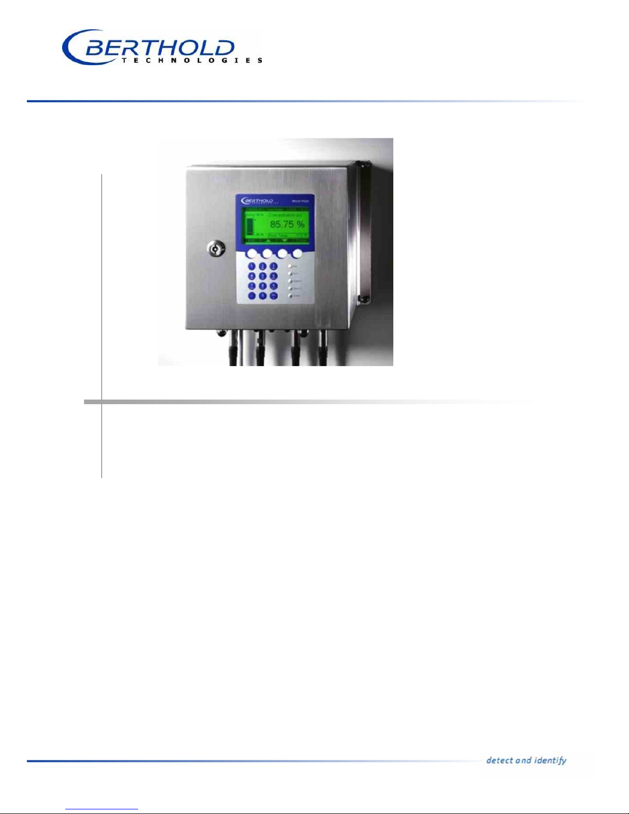
MicroPolar (++) LB 566
The units supplied should not be repaired by anyone other than Berthold
Technologies Service engineers or technicians by Berthold Technologies.
In case of operation trouble, please address to our central service department
(address see below).
The complete user’s guide consists of the hardware manual and the
software manual.
The hardware manual comprises:
mechanical components
installation
electrical installation
technical data
electrical and mechanical drawings
The software manual comprises:
operation of the evaluation unit
parameter description
basic setup
calibration
error messages
The present manual is the hardware description.
Subject to change without prior notice.
BERTHOLD TECHNOLOGIES GmbH & Co. KG
Calmbacher Str. 22 D-75323 Bad Wildbad
Switchboard: Service:
Phone +49 7081 177 0 Phone +49 7081 177 111
Fax +49 7081 177 100 Fax +49 7081 177 339
industry@Berthold.com Service@Berthold.com
www.Berthold.com

Table of Contents
MicroPolar (++) LB 566 5
Table of Contents
Page
Safety Summary 7Chapter 1.
1.1 Symbols and Warnings 7
1.2 General Information 8
1.3 General Safety Instructions 9
General Information 11Chapter 2.
2.1 Use and Function 11
2.2 Frequency License 12
2.3 Intended Use 14
2.4 Explanation of Terms 15
System Description 17Chapter 3.
3.1 Principle of Measurement 17
3.2 Calculation of Measured Values 18
3.3 Temperature Compensation 19
3.4 Throughput Calculation and Output 20
3.5 Mechanical Components 21
3.5.1 Evaluation Units 23
3.5.2 FlowCell 25
3.5.4 Container Probe 27
3.5.5 High-frequency Cable 30
3.6 Assembly on a Pipeline 32
3.7 Assembly on a Container 33
Getting Started 35Chapter 4.
4.1 Transport 35
4.2 Commissioning the FlowCell 36
4.2.1 Installing the FlowCell 36
4.2.2 Installing the Evaluation Unit 38
4.2.3 Connecting the HF Cable 39
4.3 Commissioning the Container Probe 41
4.3.1 Installing the Container Probe 41
4.3.2 Setting Up the Evaluation Unit 43
4.3.3 Connecting the HF Cable 43
4.5 Connecting the Evaluation Unit 45
4.5.1 Pin Configuration of the Connector Strip 46
4.5.2 Digital Outputs, Relay 48
Service instructions 51Chapter 5.
5.1 General Information 51
5.2 Wear Parts 52
5.3 Instrument Cleaning 53
5.4 Battery 53
5.5 Fuse Replacement 54

Table of Contents
6 MicroPolar (++) LB 566
Technical Data 55Chapter 6.
6.1 Technical Data Evaluation Unit 55
6.2 Technical Data Sensors 58
6.3 Technical Data HF Cable 61
6.4 Format of Serial Data Output RS232 and RS485 62
Certificates 63Chapter 7.
7.1 EC Declaration of Conformity 63
7.2 Frequency License 65
Technical Drawings 73Chapter 8.
8.1 Dimensions Drawings Evaluation Unit Wall Housing 73
8.2 Electrical Wiring Diagram 75
8.3 Dimensional Drawings FlowCell 76
8.3.1 Type LB 5660-102-00X FlowCell DN 50 VFL. FOA 76
8.3.2 Type LB 5660-112-00X FlowCell DN 50 G-BS/M 77
8.4 Dimensional Drawings Container Probes 78
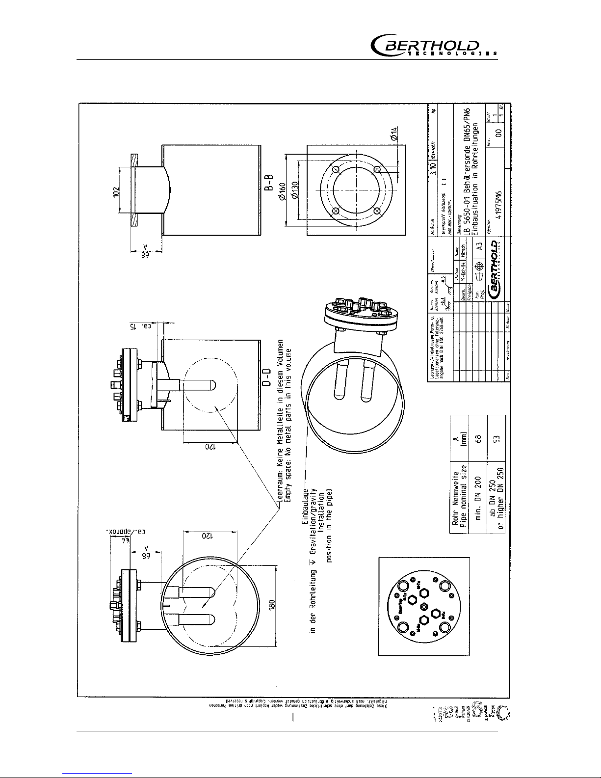
8.4.1 Type LB 5650-01 78
8.4.2 Type LB 5650-02 79
8.4.3 Type LB 5650-03 80
8.4.4 Type LB 5650-04 81
8.4.5 Type LB 5650-05 82
8.4.6 Type LB 5650-09 83
8.4.7 Installation Situation in Pipelines 84
8.5 Dimensional Drawings Container Flush Probes 85
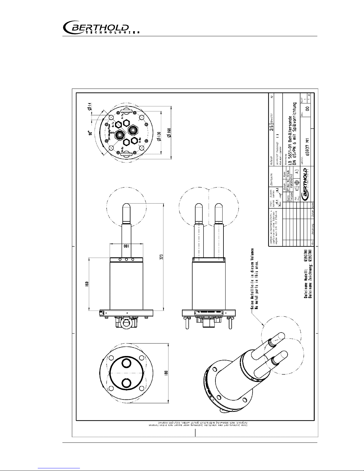
8.5.1 Type LB 5651-01 85
8.5.2 Type LB 5651-02 86
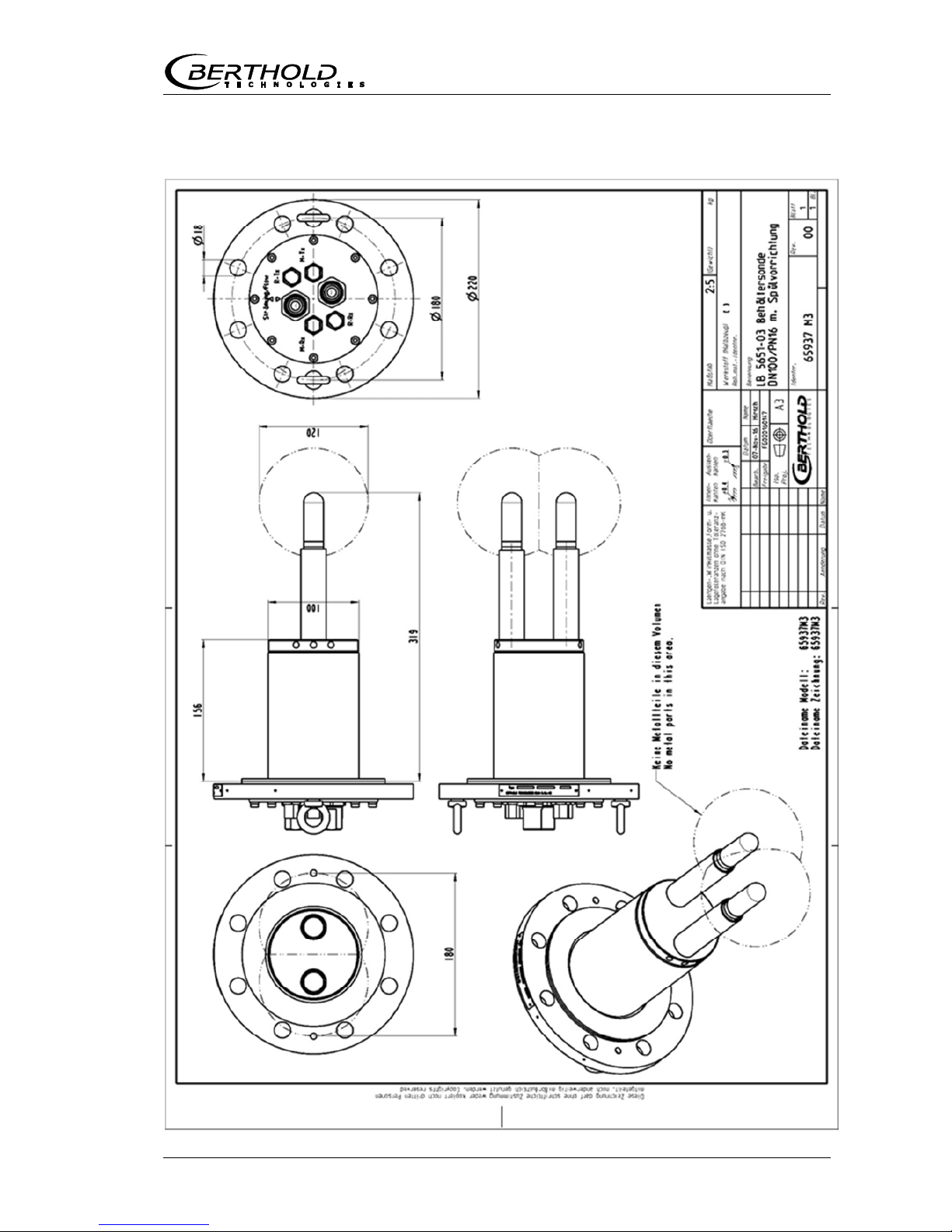
8.5.3 Type LB 5651-03 87
8.5.6 Installation Situation in Pipelines 88

Chapter 1. Safety Summary
MicroPolar (++) LB 566 7
Safety SummaryChapter 1.
1.1 Symbols and Warnings
In this user manual, the term Berthold Technologies stands for
the company Berthold Technologies GmbH & Co.KG.
To rule out bodily injury and property damage, please keep in
mind the warning and safety instructions provided in this user
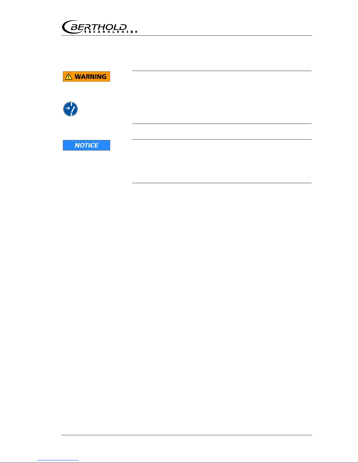
manual. They are identified by the following sings: DANGER,
WARNING, CAUTION or NOTICE.
Indicates imminent danger. If it cannot be avoided,
death or most severe personal injuries may be the
consequence.
Indicates a possibly dangerous situation. The consequences
may be death or most severe personal injuries.
Indicates a possibly harmful situation The consequences
may be minor or medium personal injuries.
Indicates a situation that may cause material damage if the
instructions are not followed.
IMPORTANT
Paragraphs with this symbol provide important information on
the product and how to handle it.
TIP
Contains user tips and other useful information.

Chapter 1. Safety Summary
8 MicroPolar (++) LB 566
Other symbols used in this documentation:
Warning: No intervention, do not alter anything
Requirement: Disconnect power
Requirement: Wear safety boots
1.2 General Information
The most important safety measures a summarized in this user
manual. They supplement the corresponding regulations which
must be studied by the personnel in charge.
Please pay attention to:
the national safety and accident prevention regulations
the national assembly and installation directions
the generally recognized engineering rules
the information on transport, assembly, operation, service,
maintenance
the safety instructions and information in these operating in-
structions
the enclosed technical drawings and wiring diagrams
the characteristic values, limit values and the information on
operating and ambient conditions on the type labels and in
the data sheets
the signs on the devices
the country-specific licensing schemes

Chapter 1. Safety Summary
MicroPolar (++) LB 566 9
1.3 General Safety Instructions
IMPORTANT
The equipment housings have IP 65 protection and are
suitable for outdoor applications. The units are factory tested
and are delivered in a condition that permits safe and reliable
operation.
For outdoor applications, the measuring systems must be
protected from direct sunlight and rain, for example by a
suitable shelter.
IMPORTANT
Never change the installation and the parameter settings
without a full knowledge of these operating instructions, as
well as a full knowledge of the behavior of the connected
controller and the possible impact on the operating process to
be controlled.
The systems may only be used in perfect technical condition
and only for the intended use!
Only let persons work with the systems who are mandated to
do this and are suitably qualified and adequately trained!
Installations and modifications on the systems which may
affect the operational safety are not permitted!
IMPORTANT
All system components require non-corrosive ambient
conditions during transport, storage and operation.
IMPORTANT
If liquid gets inside the instrument, cut off the power supply.
The equipment must be inspected and cleaned by an authorized service center.
Ambient
conditions
Chapter 1. Safety Summary
10 MicroPolar (++) LB 566
Electrical hazards
Disconnect power to ensure that contact with live part is
avoided during installation and when servicing.
Disconnect the power supply before opening the instrument.
Work on open and live instruments is prohibited.
Caution! Potential hazards, material damage!
Device type:
LB 566-12 MicroPolar ++ (ID no. 51833-02)
When connecting the 24 V DC power supply, the + and –
poles must be connected correctly. There is no reverse
polarity protection!
Spare fuses must match the rating specified by the device
manufacturer. Short-circuiting or manipulation is not permitted.
IMPORTANT
The LB 566 and all additional equipment must be connected to
mains via grounded connection.
IMPORTANT
The concentration meter LB 566 may be installed, serviced
and repaired only by qualified specialists.
Qualified persons Qualified specialists are persons who through professional
training have acquired sufficient skills in the respective field and
who are familiar with the relevant national industrial safety regulations, accident prevention directions, guidelines and accepted
engineering standards. They must be able to safely assess the
results of their work and they must be familiar with the contents
of these user manual.

Chapter 2. General Information
MicroPolar (++) LB 566 11
General InformationChapter 2.
2.1 Use and Function
The MicroPolar LB 566 has been designed as a concentration
measuring system and may be used only for this purpose. If the
devices are used in a manner that are not described in this user
manual, the protection of the devices is compromised and the
warranty will be lost.
Berthold Technologies is liable and guarantees only that the devices comply with its published specifications. The LB 566 may
only be installed in an undamaged, dry and clean condition. Alterations and modifications to the system components are not
permitted.
The LB 566 is not qualified as a "safety-related measurement".
The standards and guidelines the LB 566 complies with are
itemized in these device instructions in chapter 2.2 Frequency
License and chapter 7.1 EC Declaration of Conformity.
The protection type of the LB 566 to IEC 60529 is max. IP 65.
The following use is inappropriate and has to be prevented:
The use under conditions other than the terms and condi-
tions stated by the manufacturer in their technical documentation, data sheets, operating and installation manuals and
other specifications.
The use after repair by persons not authorized by Berthold
Technologies.
The use in a damaged or corroded state.
Operation with open or inadequately closed cover.
Operating with insufficiently tightened adapters and cable
glands.
Operation without the manufacturer’s recommended safety
precautions.
Manipulating or bypassing existing safety facilities.
Authorized persons are those who, by law, are permitted to perform the respective activity, or who have been approved by
Berthold Technologies for certain activities.
Conformity to
standards
Protection type
Warning
against misuse
Authorized persons
Chapter 2. General Information
12 MicroPolar (++) LB 566
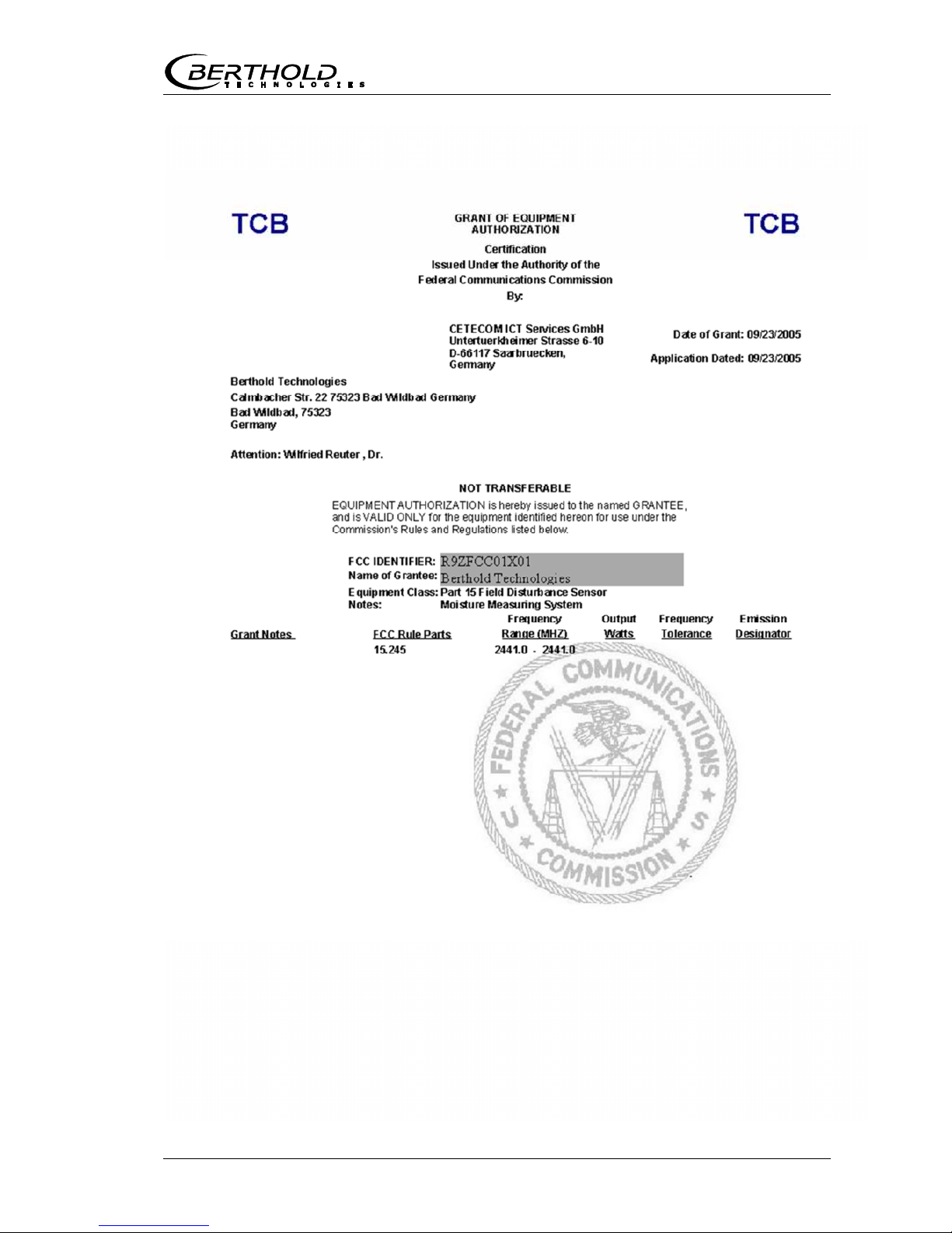
2.2 Frequency License
This device complies with Part 15 of the FCC Rules and with Industry Canada licence-exempt RSS standard(s).
Operation is subject to the following two conditions:
(1) this device may not cause harmful interference, and
(2) this device must accept any interference received,
including interference that may cause undesired
operation.
Le présent appareil est conforme aux CNR d'Industrie Canada
applicables aux appareils radio exempts de licence.
L'exploitation est autorisée aux deux conditions suivantes:
(1) l'appareil ne doit pas produire de brouillage, et
(2) l'appareil doit accepter tout brouillage radioélectrique
subi, même si le brouillage est susceptible d'en
compromettre le fonctionnement.
This equipment has been tested and found to comply with the
limits for a Class B digital device, pursuant to part 15 of the FCC
Rules. These limits are designed to provide reasonable protection against harmful interference in a residential installation.
This equipment generates, uses and can radiate radio frequency
energy and, if not installed and used in accordance with the instructions, may cause harmful interference to radio communications. However, there is no guarantee that interference will not
occur in a particular installation. If this equipment does cause
harmful interference to radio or television reception, which can
be determined by turning the equipment off and on, the user is
encouraged to try to correct the interference by one or more of
the following measures:
- Reorient or relocate the receiving antenna.
- Increase the separation between the equipment and re-
ceiver.
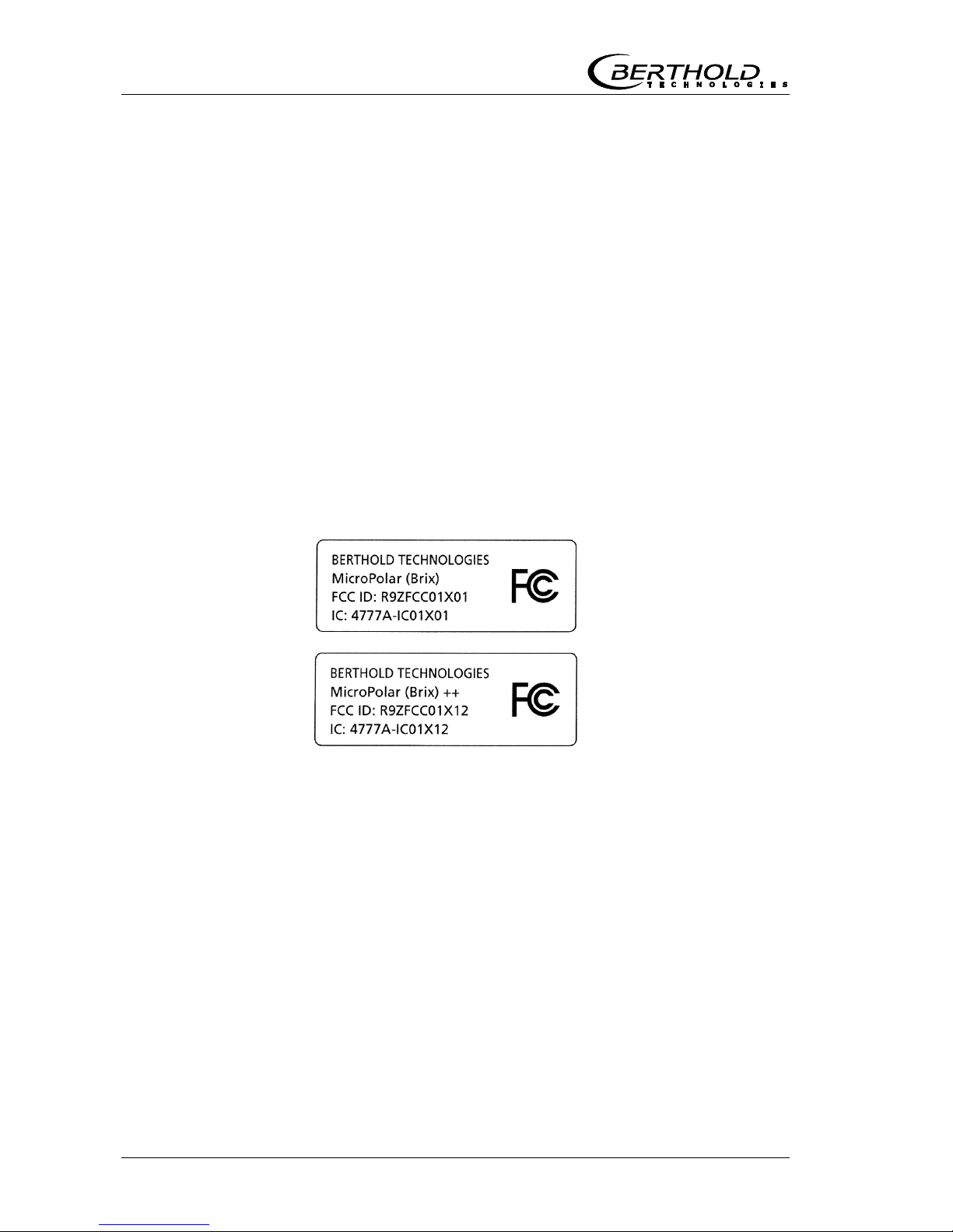
License labels

Chapter 2. General Information
MicroPolar (++) LB 566 13
- Connect the equipment into an outlet on a circuit differ-
ent from that to which the receiver is connected.
- Consult the dealer or an experienced radio/TV technician
for help.
Changes or modifications made to this equipment not expressly
approved by BERTHOLD TECHNOLOGIES may void the FCC authorization to operate this equipment.
The MicroPolar and MicroPolar ++ comply with the R&TTE Directive 1999/5/EC and thus meet all the requirements for this
type of high-frequency devices. As a mark of conformity in accordance with the CE mark, the devices bear the no. 0682 of
the certification body. The certificate can be found in chapter
7.3 Frequency License.
IMPORTANT
The frequency approvals and conformities are only applicable
in combination with the container probes and the FlowCell.
To comply with ETSI (European Telecommunications Standards Institute), the LB 566 ++ in combination with horn and
spiral antennae may only be operated with a 10dB attenuator
pad in the sending path (MTX).
IMPORTANT
The LB 566 has been manufactured in compliance with the
safety requirements for microwave devices. It will be the
user’s responsibility to adhere to any special legal provisions
regarding the use of microwaves.
IMPORTANT
Any change in the frequency or otherwise tampering with the
microwave device will lead to a loss of the frequency license
and may result in criminal consequences.
The microwave modules do not include any replaceable
components and must not be opened.

Chapter 2. General Information
14 MicroPolar (++) LB 566
2.3 Intended Use
The LB 566 can be used to determine the water or moisture
content and the concentration of virtually any material. The following sensors and evaluation versions are available:
1. The container probes have been designed for installation into containers and pipelines with a nominal width of 200
mm. The probe is mounted so that both measuring rods
(transmitter and receiver) are immersed into the product
being measured.
2. The FlowCell is a tubular probe, with the microwave transmitter and receiver being firmly welded onto the outside of
the tube. The tube is lined with Teflon to ensure smooth
walls. The FlowCell is either installed directly into the existing pipeline system or into a bypass.
The evaluation unit is available in two versions: The standard
model MicroPolar and the high dynamic version MicroPolar ++.
The Micro Polar ++ requires a microwave signal attenuation of
at least 40 dB. The MicroPolar must be used for lower microwave attenuation.
During operation, the concentration meters MicroPolar and MicroPolar ++ emit electromagnetic radiation in the frequency
range between 2.4 GHz and 2.5 GHz (range limitations depending on local regulations in your country). Microwaves are not
dangerous to human beings and the environment (power radiation < 10 mW). The microwaves are emitted directed from the
microwave window; the product is not altered by the microwaves.
To ensure proper function of the measuring system, please pay
attention to the following:
TIP
The material to be measured may be electrically conduc-
tive only to a limited degree.
The product must not contain any gas bubbles or gas
bubbles have to be compressed with adequate pressure
when carrying out measurements in pipelines.
The ion concentration, for example, salt content must be
nearly constant.

Chapter 2. General Information
MicroPolar (++) LB 566 15
2.4 Explanation of Terms
Attenuation Weakening of microwave signals, microwaves measuring effect.
EVU Evaluation Unit
Factory setting In the factory setting all parameters have been set to default
values. In most cases this considerably facilitates the calibration of the instrument. Despite factory setting, calibration
always has to be performed.
FlowCell Tubular probe for simple integration into the existing pipeline
system.
Flush probe Container probe with flushing device.
HF cable High frequency cable
Microwaves Designation for electromagnetic waves in a specific frequency
range.
Phase Phase or phase shift, microwave measuring effect.
Quad cable Combination of four HF cables of equal length in a corrugated
tube.
Softkeys Software associated keys.
TC Temperature compensation


Chapter 3. System Description
MicroPolar (++) LB 566 17
System DescriptionChapter 3.
3.1 Principle of Measurement
As the microwaves pass through the product, their propagation
velocity is slowed down (= phase shift) and their intensity is attenuated (= attenuation). Figure 3-1 illustrates the principle of
measurement: Compared to a reference signal, the propagation
velocity of microwaves passing through the product is slowed
down (phase shift) and their intensity (attenuation) is reduced.
Phase shift
Messgut
Phase comparison
--> Phase
Amplitude comp.
--> Attenuation
Referencepath
Referencesignal
Measurementsignal
Measured value:
Concentration %DS
HF sources
Receiver
Transmitter
The prerequisite is that the product being measured shows dielectric properties. Generally, water is a very distinct dielectric
fluid. The water or dry mass concentration can therefore be determined by measuring the phase shift and/or attenuation.
The concentration to be detected in the product is therefore in
good approximation linearly dependent on the phase shift and
the attenuation. For this reason, we can measure the concentration or the dry matter content of the product using a linear
calibration (see chapter 3.2 Calculation of Measured Values).
Figure 3-1:
Schematic diagram:
Change in
microwave by
product

Chapter 3. System Description
18 MicroPolar (++) LB 566
3.2 Calculation of Measured Values
The microwave parameters phase and attenuation are calibrated according to an automatic plausibility analysis.
During calibration, the phase and/or attenuation of a concentration value (or density value) are assigned through sampling.
The calibration is done automatically and the sampling process
is supported by the evaluation unit.
Which of the parameters (phase, attenuation or both) will be
used for the calibration depends on the size and interference of
the measuring effect. For example, the attenuation is significantly more sensitive to electrolytic conductivity (salt content).
In many cases, the pure phase measurement is recommended
and the measured value is calculated as follows:
Measured value = A ∙ Phase + C Eq. 3-1
where:
Measured value Concentration / Moisture / Dry matter
A, C Coefficients of the respective calibration
function
The LB 566 allows you to calibrate, display and output two concentrations: Con1 and Con2. You have to enter the calibration
coefficients separately for concentration 1 and 2. For more information please refer to the Software Manual.
Limitations
Weakly bound water can be detected depending on the
strength of the binding. Thus, the measuring effect may be
dependent on the grain size distribution and the chemical
properties of the product being measured, provided this
changes the binding of water to the solid matter.
Walls made of plastic, rubber or insulation materials with
fairly low dielectricity hardly affect the measurement and are
calibrated at a constant level.
Ice and crystal water cannot be measured because the water
molecules cannot rotate freely (ice and crystal water are
dry).

Chapter 3. System Description
MicroPolar (++) LB 566 19
Conductive materials such as graphite or coke cannot be transmitted by microwaves. Metal walls can also not be transmitted
by microwaves.
Compensation In addition to the water content, the product temperature,
product density and a varying material load (varying microwave
irradiation path) may have an influence on the phase and attenuation. This influence has to be compensated for during calibration.
3.3 Temperature Compensation
Temperature compensation (TC) is required for fluctuating
product temperature. It is generally advisable to provide a temperature compensation, i.e. a temperature signal (0/4...20 mA
or PT100) to be connected to the evaluation unit and, optionally, to enable the compensation in the evaluation unit. The evaluation unit is designed so that the required TC’s can be calculated automatically. The variation in temperature where TC becomes absolutely essential is dependent on the product and on
the water content. In the first approximation, 2° C should be
set as fluctuation limit.
For example, if the product temperature is measured via the
PT100 input, then Eq. 3-1 is expanded as follows:
Measured value = A · Phase + D · T
meas
+ C Eq. 3-2
where:
Measured value Concentration / Moisture / Dry matter
A, D, C Coefficients of the calibration function
T
meas
Product temperature
How to work with the temperature compensation is described in
detail in the Software Manual.

Chapter 3. System Description
20 MicroPolar (++) LB 566
3.4 Throughput Calculation and Output
For pipeline applications, the LB 566 allows you to calculate the
throughput (mass flow) and to output the result via a current
output.
The calculation is based on the microwave measured value; if
this value correlates with the product density, one can calculate
the throughput, if some additional information is available. The
additional information needed is: internal pipe diameter/cross
section and the product speed. The product speed has to be fed
via current input.
For details, please see the Software Manual, chapter 4.2.12
Mass Flow.

Chapter 3. System Description
MicroPolar (++) LB 566 21
3.5 Mechanical Components
The measuring system comprises an evaluation unit, a
probe/antenna pair and one set of special high-frequency cables
(short HF-cable). The evaluation unit is available in two versions: the standard model MicroPolar LB 566 and the high dynamics version MicroPolar ++ LB 566 (see Figure 3-4 and Figure 3-5).
Figure 3-4:
Evaluation unit
MicroPolar
LB 566
Figure 3-5:
Evaluation unit
MicroPolar ++
LB 566

Chapter 3. System Description
22 MicroPolar (++) LB 566
The probes/antenna pairs are available in different versions, as
pipeline and container probe with or without flushing device
(see Figure 3-6 to Figure 3-7).
The FlowCell is available in the nominal pipe sizes 50 -150 mm
(50, 65, 80, 100, 125 and 150) The following connections types
are available:
Hygiene milk pipe screw connection DIN 11853
V flange EN 1092-1
Figure 3-6:
From left:
Container probe
LB 5650 and
LB 5651 with
flushing device
Figure 3-7:
FlowCell LB 5660-102-00x
nominal width 50 mm
with V flange

Chapter 3. System Description
MicroPolar (++) LB 566 23
3.5.1 Evaluation Units
The evaluation units comprise the evaluation computer and the
microwave unit. The microwaves are generated, received and
analyzed in the microwave unit. Signal processing and communication take place in the evaluation computer. For simple operation, the measuring system includes a display, 4 softkeys and
an alphanumeric keypad. Different functions are assigned to the
softkeys on the display.
Differences between MicroPolar ++ und MicroPolar
The MicroPolar ++ evaluation unit has an additional HF amplifier
module in comparison to the standard model; therefore, it also
has a larger wall housing (dimensions see chapter 6.1 Technical
Data Evaluation Unit). Otherwise, the evaluation units differ only in their application.
MicroPolar ++ The high dynamics version MicroPolar ++ permits higher
product attenuations. Larger measuring paths can be irradiated,
i.e. flow cells with larger nominal diameters can be used. Which
type of evaluation unit is used depends on the product attenuation. MicroPolar is used up to an attenuation of 50 dB; MicroPolar ++ is used for higher attenuations. The MicroPolar ++ generally requires an attenuation of 40 dB. If this attenuation is not
reached, the software displays an error message.
An RS232 interface is included on the bottom side of the instrument.
and cable feed-through
Lock
Numerical
keypad
Softkey buttons
LED’s
LCD display
RS232 connection
HF connections for
signal cable reference cable
Micro-Polar
Figure 3-8:
Evaluation unit –
front view

Chapter 3. System Description
24 MicroPolar (++) LB 566
Interpretation of LEDs
Five LEDs on the instrument front panel indicate the current de-
vice status.
LED Function
Run On: Device in measurement mode
Flashes + ERROR LED off: Device in warning
state, on hold, paused or low load state.
A display message with error code indicates the
cause (see Software Manual, chapter 11. Error
Lists and Device States).
Error On: Device in error state.
A display message with error code indicates the
cause (see Software Manual, chapter 11. Error
Lists and Device States).
Canceled after reset or if error has been eliminated.
Signal 1 Display depending on the selected function of
relay 1, possible functions:
Error, no product, alarm min., alarm max.,
measurement stopped, low load
Signal 2 Display depending on the selected function of
relay 2, possible functions:
Error, no product, alarm min., alarm max.,
measurement stopped, low load
Comm Communication active, e.g. via RS232 and RS485
Figure 3-9:
Evaluation unit –
bottom view
Figure 3-10:
LEDs on the
front panel of
the evaluation unit
Run
Error
Signal 1
Signal 2
Comm
Cable feed-through
M 20 and M 16
High-frequency connections
Rs232
9 pole SubD-connector
M-TxM-Rx R-Tx
R-Rx

Chapter 3. System Description
MicroPolar (++) LB 566 25
Terminal block
The electrical connections of the LB 566 are located on a connector strip in the wall cabinet. The terminal block can be accessed from the front by opening the cover of the housing.
There, you also find the power cut-off switch and the fuses. The
high-frequency terminals are located on the outside of the
housing. All other elements, especially the voltage-carrying elements (on the motherboard) are provided with a protective
cover.
3.5.2 FlowCell
The FlowCell is available in the nominal sizes of 50 to 150 mm
(see fig. 3-11). As connection, the versions V flange EN 1092-1
or Hygiene milk pipe screw connection DIN 11853 are available.
For technical data please see chapter 6.2 Technical Data Sen-
sors.
A: with V flange EN 1092-1
B: with Hygiene milk pipe screw connection DIN 11853
Figure 3-11:
FlowCell versions

Chapter 3. System Description
26 MicroPolar (++) LB 566
The flow cell consists of a sturdy stainless steel body. The microwave transmitter and receiver are firmly welded to the outside of the pipe. The entire product pipe is PTFE-coated and
thus meets the special requirements for use in food for use in
food.
There are no objects that extend into the pipe (e.g. a measuring
sensor). Depending on the version, the FlowCell can be mounted with the V flange or milk pipe screw connection to the piping.
For the versions with V flange, ASA adapter flanges are available as accessory.
The FlowCell has two HF ports to feed in and output the microwave signals. The input and output can be allocated as needed
(M-Tx, M-Rx). The microwave signals transmit the product over
the entire pipeline cross-section.
For all versions, the following accessories are available:
1. Pipe-mounted PT100 or Inline PT100
2. Conductivity measuring device
3. Sampling valve

Chapter 3. System Description
MicroPolar (++) LB 566 27
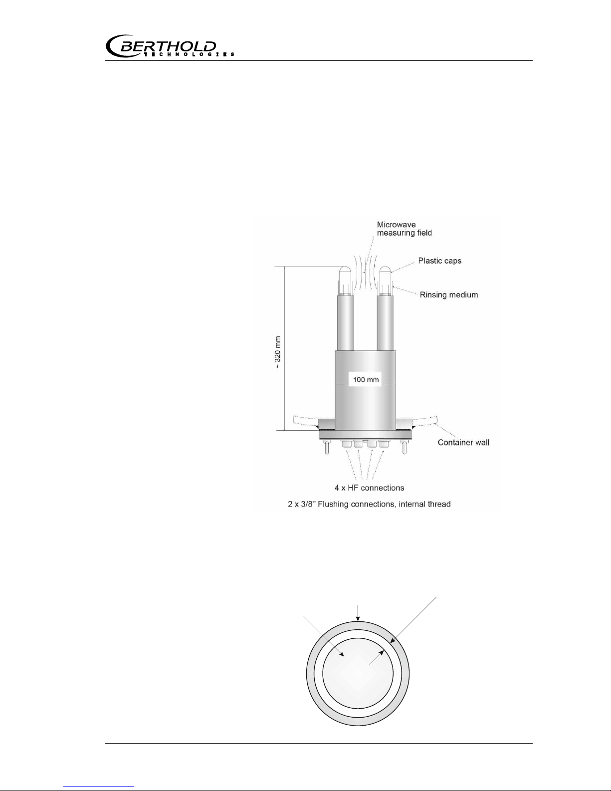
3.5.4 Container Probe
The container probe is available in a version with and without
flushing device (see Figure 3-12). The technical data are listed
in chapter 6.2 Technical Data Sensors.
A: High-frequency connections
B: Process connection, flanges of different sizes
Container probe type LB 5650 and type LB 5651
The container probe has been specially designed for concentration measurements in containers. Both measuring rods are immersed into the product. Microwaves are emitted from one end
of the rod and received by the other end of the rod; they are
emitted only towards the opposite end of the rod. This directional characteristic of the probe minimizes the interfering influence of metal parts in the vicinity of the probe and allows installation if only limited space is available. For example, the concentration of sugar strike can be measured continuously to find
the suitable inoculation time.
The plastic caps of the measuring rods meet the special requirements for application in foodstuffs.
Two different probe types are available:
The standard type is the container probe without flushing
device.
The flushing probe is used in processes where incrustations
are likely to occur, for example, due to increased depositions. The flushing device prevents deposition on the microwave exit windows.
Figure 3-12:
Container probe
versions

Chapter 3. System Description
28 MicroPolar (++) LB 566
For the case depicted in Figure 3-13, the flow direction of the
product being measured must be perpendicular to the drawing
plane. This ensures a representative product between the
measuring rods, provided the product is mixed thoroughly.
The container probe LB 5650 is the only one equipped with a
PT100 connection and can be connected to the evaluation unit
via a 4-core cable. The PT100 wiring diagram is described in
chapter 4.6.1 Pin Configuration of the Connector Strip. To minimize the danger of incrustation in the immediate vicinity of the
measuring rods, the container flush probe is not provided with a
PT100.
Warning: Possible material damage!
Do not open the cover screws on the front of the container
probes, see Figure 3-14.
Figure 3-13:
Container probe LB 5650
Figure 3-14:
Front view
container probe
PT100
Chapter 3. System Description
MicroPolar (++) LB 566 29
Container probe type LB 5651 with flushing device
The flushing probe LB 5661 has been designed for processes in
which depositions, for example, due to incrustations are likely to
occur on the probe.
The flushing probe has two flushing channels which keep the
measuring rods free from incrustations; this ensures that the
microwaves come into direct contact with the product being
measured. All probe parts coming into contact with the product
meet the special requirements for application in foodstuffs. Fig-
ure 3-15 shows the probe design.
The flushing slit width is the same for both probe rods and is
depicted in Figure 3-16.
Figure 3-15:
Flushing probe
LB 5651
Figure 3-16:
Rod head with
flushing pipe
Plastic rods
Flushing pipe
Flushing
s
l
i
t
~
1.5
m
m
Chapter 3. System Description
30 MicroPolar (++) LB 566
3.5.5 High-frequency Cable
High-frequency cables (HF cable) are used to transmit microwave signals.
HF cables change their conductivity (for microwaves) with temperature and would therefore produce measurement errors with
varying ambient temperature. This error is compensated for by
enabling the automatic cable compensation. The influences of
the ambient temperature on the signal cable are compensated
for by means of the reference cable. To this end, the sum of the
reference cables has to match the length of the sum of the signal cables.
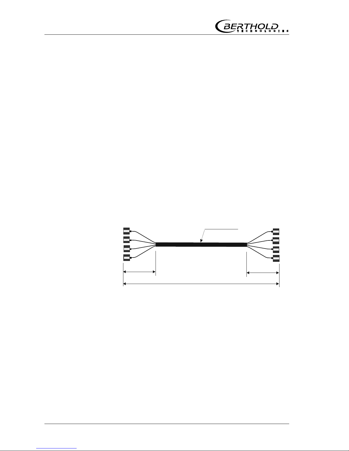
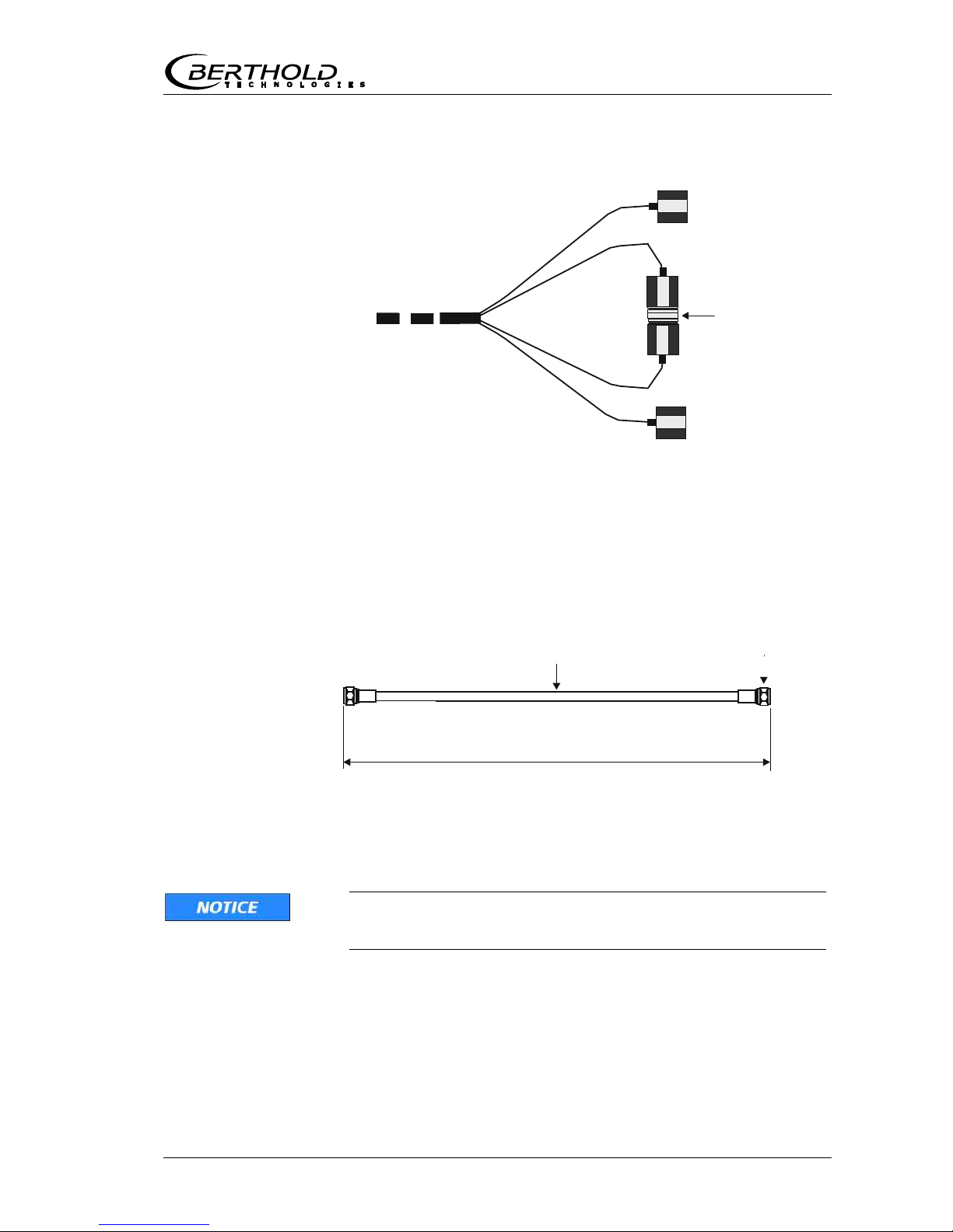
Two different HF cable types of different lengths are available:
Version 1: The so-called HF-cable quad: It consists of four single HF-cables of equal length, whose ends are terminated by
one HF-connector (N-type). Available cable lengths: 2, 4, 6 and
10 m (see Figure 3-17).
The HF-cable quad is used exclusively for the container probe
and the FlowCell. For the FlowCell, the reference line on the
probe side is short-circuited using an N-connector (see Figure 3-
18).
Figure 3-17:
HF cable quad
Lengths 2, 4, 6 and 10 m
Corrugated tube
4 x N-connector
ø18.5 mm
0.35 m
0.35 m
4 x N-
4 x N-connector
Chapter 3. System Description
MicroPolar (++) LB 566 31
Figure 3-18:
HF cable quad
probe side:
The ends of the
reference line
R-Rx and R-Tx are
short-circuited
using an
N-connector.
N-connector
(ID-no. 20608)
Sensor side
R
-
R
x
R
-
T
x
M
-
R
x
M
-
T
x
Version 2: It consists of a single HF-cable whose ends are terminated by an HF-connector (N-type). Available lengths: 2, 2.5,
3, 3.5 and 4 m (see Figure 3-19).
Figure 3-19:
HF cable
Lengths 0.5 to 4 m
ø10 mm
19 mm wrench
For further technical data see chapter 6.5 Technical Data HF-
Cable.
During assembly, ensure that the end of the corrugated tube
is bent down on the probe side. By doing so, the ingress of
fluids into the corrugated tube is prevented.

Chapter 3. System Description
32 MicroPolar (++) LB 566
3.6 Assembly on a Pipeline
The evaluation unit is installed close to the FlowCell to keep the
HF cable between evaluation unit and probe as short as possible. The shorter the cable connection, the better the stability of
the measurement. The standard length is 2 m and the maximum length of the HF cable is 10 m. The HF cable must be at
least 2 m long.
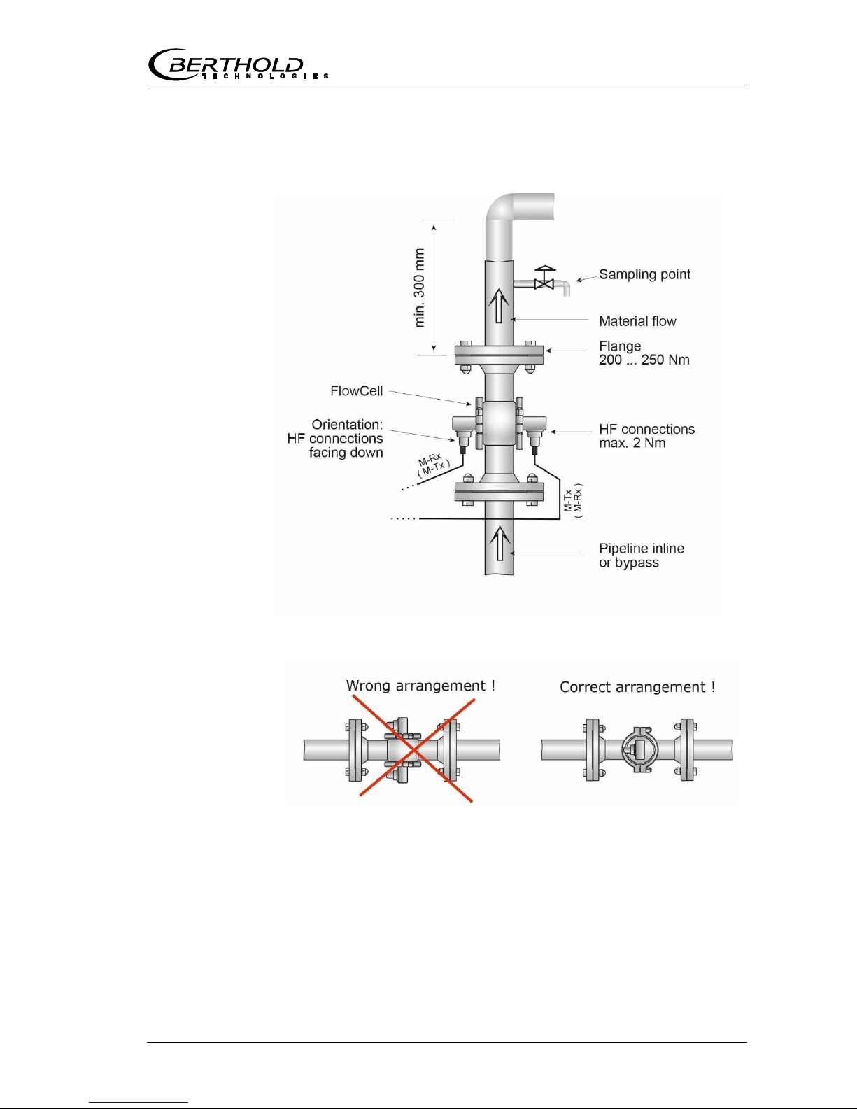
The FlowCell is integrated into the existing pipeline system or in
a bypass. The orientation of the FlowCell can either be vertical
or horizontal. To avoid possible sedimentary deposits, vertical
installation in a riser is preferred (see Figure 3-20).
The installation should preferably be close to a sample sampling
point to ensure representative sampling for calibration.
A representative temperature signal (current signal or PT100)
should be connected to the evaluation unit for product temperature compensation.
Figure 3-20:
Typical measurement
arrangement on
a pipeline

Chapter 3. System Description
MicroPolar (++) LB 566 33
3.7 Assembly on a Container
The evaluation unit is installed in the immediate vicinity of the
container probe to keep the HF-cable between evaluation unit
and probe fairly short. The shorter the cable connection, the
better the stability of the measurement. The standard length is
2 m and the maximum length of the HF cable is 10 m. The HF
cable must be at least 2 m long.
The installation should preferably be close to a sampling point
to ensure representative sampling for calibration. A representative temperature signal (current signal or PT100) should be
connected to the evaluation unit for a possibly required product
temperature compensation.
Our example in Figure 3-21 shows the measurement configuration on a process container. The probe is fixed to the container
wall using a flange coupling so that both measuring rods are
immersed into the product.
Figure 3-21:
Example:
Pipeline measurement
configuration on a
process container


Chapter 4. Getting Started
MicroPolar (++) LB 566 35
Getting StartedChapter 4.
4.1 Transport
Warning: Possible material damage!
System parts may get damaged during transportation!
Transport all components in their original packaging.
Protect parts against shocks.
In particular, the measuring rods of the container probes must
be protected against mechanical shock!
After unpacking, make sure all parts listed on the packing list
have been delivered and show no sign of damage; if necessary,
clean these parts.
If you detect any damage, please notify the forwarder and the
manufacturer immediately.
The weight of the system components may exceed 25 kg,
depending on the version. We recommend, therefore, that you
wear safety boots.

Chapter 4. Getting Started
36 MicroPolar (++) LB 566
4.2 Commissioning the FlowCell
4.2.1 Installing the FlowCell
Note the following points when installing the FlowCell:
The FlowCell is integrated at a suitable location in the pipe-
line system. Keep in mind that material sampling directly
behind the FlowCell should be possible for calibration.
The FlowCell should be installed in a vertical riser, if possi-
ble. It must be ensured that material deposits cannot form
on the pipe walls and no bubble formation occurs in the
product. In case of horizontal installation, please observe
the correct orientation of the HF connections, see Figure 4-
2.
There should be a straight pipe section of at least 300 mm
and equal nominal width before and after the FlowCell to ensure a fairly homogeneous flow profile and to rule out possibly occurring microwave reflections in the pipeline. Also, not
fittings must be installed in these pipe sections.
No gas inclusions should be present in the product. If gas
bubbles cannot be ruled out, a pressure of at least 4 bar is
required in the pipeline to minimize the influence of gas
bubbles. Please observe the max. permissible operating
pressure, see chapter 6.2 Technical Data Sensors.
The high-frequency cables should preferably be connected to
the FlowCell from below to prevent flowing water from getting to the connection sockets.
The signal and reference cable should as far as possible fol-
low the same path to make sure both cables are exposed to
the same temperature and should not come into contact
with hot pipelines. We recommend installing the HF cable
through a single protection tube. If you are working with the
HF cable quad, this function is taken over in good approximation by the corrugated tube.
Chapter 4. Getting Started
MicroPolar (++) LB 566 37
Abb. 4-2:
Horizontal installation:
Orientation of
HF connectors
Abb. 4-1:
Installation in a
vertical riser

Chapter 4. Getting Started
38 MicroPolar (++) LB 566
4.2.2 Installing the Evaluation Unit
Note the following points when installing the evaluation unit:
Position the evaluation unit depending on the length of the
HF cable in the vicinity of the microwave probe.
The evaluation unit has to be protected against vibrations.
In some cases, it is advisable to set up the evaluation unit
on a stand separated from the pipeline system.
For instrument installation you should foresee a cutoff de-
vice to allow easy and quick disconnection of the device
from the power supply.
Provide an automatic separating device (line circuit breaker)
that disconnects the unit from power within 0.03 seconds in
case of failure. The separating device must be matched to
the cable cross-section of the supply line, but at least it
must be designed for 1 A continuous current.
When installing the evaluation unit on a crystallizer, use a
distance rail to minimize the thermal radiation and conduction. See Figure 4-3:
For outdoor applications, the evaluation unit must be pro-
tected from direct sunlight and rain, for example by a suitable shelter.
Figure 4-3:
View from above:
Installation of the
evaluation unit on a
hot container wall
Insulation container wall
Spacer
Evaluation unit

Chapter 4. Getting Started
MicroPolar (++) LB 566 39
4.2.3 Connecting the HF Cable
The FlowCell is connected with the evaluation unit via the HF
cables. Two different options are available:
Version 1: 1 x HF cable quad and 1 x N-connector
Version 2: 2 x HF cables (as signal cable)
1 x HF cable (as reference cable)
The decision for a certain cable version is taken by Berthold
Technologies in the planning stage. It is subject to the application and the desired distance between evaluation unit and
FlowCell.
Prerequisite for a correct measurement is the correct installation
of cables! Please keep in mind:
TIP
Make sure the cable does not get into contact with hot pipes
over the entire length (corrugated tube and single cable
section after splitting), e.g. direct contact with the device wall
(not insulated). This will ensure that all individual cables are
exposed to the same ambient conditions and that the compensation of the cable drift works properly.
Never bend the HF cable! The bending radius should not be
less than 100 mm. Fix the HF cable with cable binders or other
suitable means, so that the cable cannot slip anymore!
During assembly, ensure that the end of the corrugated tube
is bent down on the probe side. By doing so, the ingress of
fluids into the corrugated tube is prevented.
Version 1 The HF cable quad and the HF connectors on the evaluation unit
are labeled. Connect the FlowCell to the evaluation unit as
shown in Figure 4-4; only cables with identical labeling can be
combined. The two connections on the FlowCell are not labeled,
the assignment of both cable connectors M-Tx and M-Rx is arbitrary. Connect the cable connectors R-Tx and R-Mx with the Nconnector (short-circuited).
Version 1 Connect the FlowCell to the evaluation unit as shown in Figure
4-5; make sure that the reference cable (ring line) is connected
to R-Tx and R-Mx.
The reference cable must be as long as the sum of both signal
cables.

Chapter 4. Getting Started
40 MicroPolar (++) LB 566
Hand tighten all screwed connections of the HF cable (2 Nm =
0.2 kg/m)! Before tightening, carefully screw on the cable by
hand. Caution! Threaded joint jams easily.
Check occasionally if the screwed connection is still properly
tightened. If the installation is exposed to vibrations, the
screwed connection may come loose and this may result in inaccurate measurements or corrosion of the connections.
Abb. 4-4:
FlowCell connection,
version 1
Abb. 4-5:
FlowCell connection,
version 2

Chapter 4. Getting Started
MicroPolar (++) LB 566 41
As long as the cables are not connected, the coaxial sockets
have to be covered with plastic caps and the cable connectors
have to be protected against moisture and dirt.
4.3 Commissioning the Container Probe
4.3.1 Installing the Container Probe
For installation of the probes, please keep in mind:
Select the installation site such that good mixing and a ho-
mogeneous product are ensured and no bubbles are present
in the probe. A sample tap should be available in the direct
vicinity to allow representative sampling.
The probe must be flanged to the container so that the ma-
terial to be measured flows between the two measuring
rods. That means the fork (both measuring rods) must be
installed perpendicular to the material flow.
The distance between the measuring rod tips and any metal-
ized walls (heating element, stirrer, container wall) should
be at least 60 mm.
The following mounting hole dimensions in the fitting
flange are required for installation of the probe:
Flange Minimum mounting hole size (mm)
DN 65 / PN 6 102 0.3
others 104 0.5
For further installation dimensions, such as the required in-
stallation depth, please refer to chapter 8.6 and 8.7 Assem-
bly Sheets.
Use the appropriate flat gasket (standard accessory) to
compensate for minor surface tolerances in the fitting
flange.
Installation on process containers
Figure 3-26 shows the position of the container probe on the
container. This position is also valid for the container flush
probe. Follow the instructions in chapter 3.9 Assembly on a
Container.
The assembly sheets in chapters 8.6 and 8.7 include all the information required for installation.
Depending on the process, the probe flange may stick to the
process flange. In such case, during the dismounting process,
Dismounting in the
event of a stuck
flange
Chapter 4. Getting Started
42 MicroPolar (++) LB 566
remove the two eyebolts first. Then insert two longer screws
(M8) into their bore holes up to the process flange. If you continue to rotate the screws, you will push the probe away from
the process flange.
Installation in pipelines
Container probes can be installed in pipelines with a nominal
width 200 mm using an adapter flange. Note the position and
orientation of the container probe, see the technical drawings in
chapter 8.4.7 and 8.5.6 Installation Situation in Pipelines.
Connecting the flushing pipes
The container probe with flushing device has two flushing connections with G3/8'' female thread (DIN ISO 228-1). The flushing connections should be sealed only at this thread. Sealing the
probe cover, for example with silicone, is not permitted.
Flushing parameters (only for flushing probe)
The degree of deposition or incrustation is essential for the flush
settings, i.e. flush interval and flush duration. The flushing parameters must be matched to the product and the process.
The following product and process independent flushing parameters must be strictly adhered to:
Flush solution Water, condensate
Temperature of
flush solution
Maximum 120°C
Pressure
3 bar, max. 8 bar
Fittings 2 x G3/8'' female thread (DIN ISO 228-1)
Supply pipe
1/2 inch
In general: The flushing connections can be flushed simultaneously or sequentially. The flushing parameters are valid for each
flushing connection.
TIP
The required flush duration has to take into account possible
inertias of the system, e.g. valve openings. The flush supply
pipes must be well insulated to prevent that the flush solution
is initially colder.
Amounts of water With a 5 bar flushing pressure, the amount of water per flushing
connector is approximately 0.8 liters per second.
Chapter 4. Getting Started
MicroPolar (++) LB 566 43
4.3.2 Setting Up the Evaluation Unit
Set up the evaluation unit as described in chapter 4.2.2.
4.3.3 Connecting the HF Cable
Connect the container probe to the evaluation unit via the HF
cable quad.
Prerequisite for a correct measurement is the correct installation
of cables! Please keep in mind:
TIP
Make sure the cable does not get into contact with hot pipes
over the entire length (corrugated tube and single cable
section after splitting), e.g. direct contact with the device wall
(not insulated). This will ensure that all individual cables are
exposed to the same ambient conditions and that the compensation of the cable drift works properly.
Never bend the HF cable! The bending radius should not be
less than 100 mm. Fix the HF cable with cable binders or other
suitable means, so that the cable cannot slip anymore!
The HF cables and the HF connections on the evaluation unit
and on the probe are labeled. Connect the probe to the evaluation unit as shown in Figure 4-6; only cables with identical labeling can be combined.

Chapter 4. Getting Started
44 MicroPolar (++) LB 566
Hand tighten all screwed connections of the HF cable (2 Nm =
0.2 kg/m)! Before tightening, carefully screw on the cable by
hand. Caution! Threaded joint jams easily.
Check occasionally if the screwed connection is still properly
tightened. If the installation is exposed to vibrations, the
screwed connection may come loose and this may result in inaccurate measurements or corrosion of the connections.
As long as the cables are not connected, the coaxial sockets
have to be covered immediately with plastic caps and the cable
connectors have to be protected by suitable provisions against
moisture and dirt.
Figure 4-6:
Connecting the
container probe
to the
evaluation unit
Chapter 4. Getting Started
MicroPolar (++) LB 566 45
4.5 Connecting the Evaluation Unit
Electrical hazards:
Disconnect power to rule out any contact with live parts during
installation and servicing.
Turn off power before opening the instrument.
NEVER work on open and live instruments.
Caution! Potential hazards, material damage!
Device type:
LB 566-12 MicroPolar ++ (ID no. 51833-02)
When connecting the 24 V DC power supply, the + and –
poles must be connected correctly. There is no reverse
polarity protection!
The line cross-section the for power supply must be at least 1.0
mm2.
Connect all desired input and output signals to the terminal
strip as shown on the following pages. Use the M feedthrough to keep the degree of protection.
Check if the voltage indicated on the type plate matches
your local supply voltage.
Connect the deenergized power cable to the terminals 3(L1),
2(N) and 1(PE).
Verify that the test switch (power interruption) is in position
"ON" (see Figure 5-1).
Close the instrument housing and turn on the power supply.
Chapter 4. Getting Started
46 MicroPolar (++) LB 566
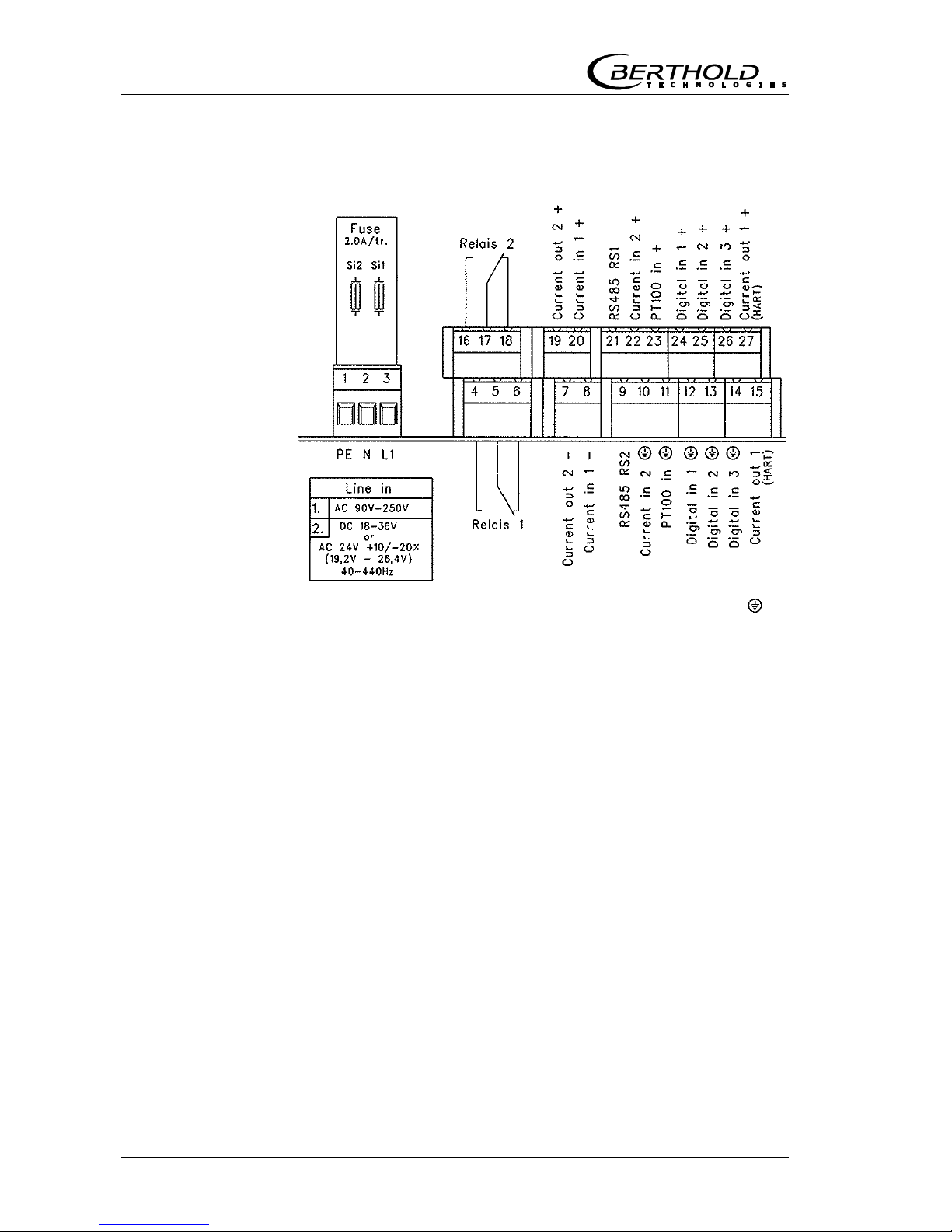
4.5.1 Pin Configuration of the Connector Strip
The connector strip of the evaluation unit includes the following
terminals:
Power supply: Terminals 3 (L1, +), 2 (N, -) and 1 (PE, )
For MicroPolar, depending on device type, see name plate on
the housing outer wall.
1.) 100…240 V AC, 45…65 Hz
2.) 24 V DC: 18…36 V
24 V AC: -20%, +5%, 40…440 Hz
For MicroPolar ++, depending on device type, see name plate
on the housing outer wall.
1.) 100…240 V AC, 45…65 Hz
2.) 24 V DC: 18…36 V, no reverse polarity protection
Current input no. 1 (terminals 20+ and 8-), insulated
Current input no. 2 (terminals 22+ and 10-), not insulated
Input as 0/4 - 20 mA signal. For example, for temperature
compensation or reference signal recording.
Current output no. 1 (terminals 27+ and 15-), insulated
Output as 4 - 20 mA signal. Output options: Concentrations (1 /
2), current input signals (1 / 2), PT100 signal, mass flow
Current output no. 2 (terminals 19+ and 7-), insulated
Output as 0/4 - 20 mA signal. Output options same as for cur-
rent input no. 1.
Figure 4-7:
LB 566 wiring diagram
Chapter 4. Getting Started
MicroPolar (++) LB 566 47
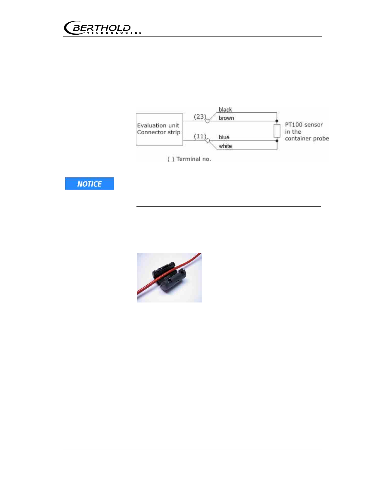
PT100 (terminals 23+ and 11-)
Connection for temperature measurement.
When commissioning the container probe, connect the 4-core
cable of the PT100 to the connector strip of the evaluation (see
fig. 4-8). Connect the other end of the cable with the corresponding plug on the container probe (see fig. 4-6).
In the delivered state, the PT100 cable has a length of 10
meters. We recommend shortening the cable to the required
length.
Combine the two core pairs in accordance with figure 4-8.
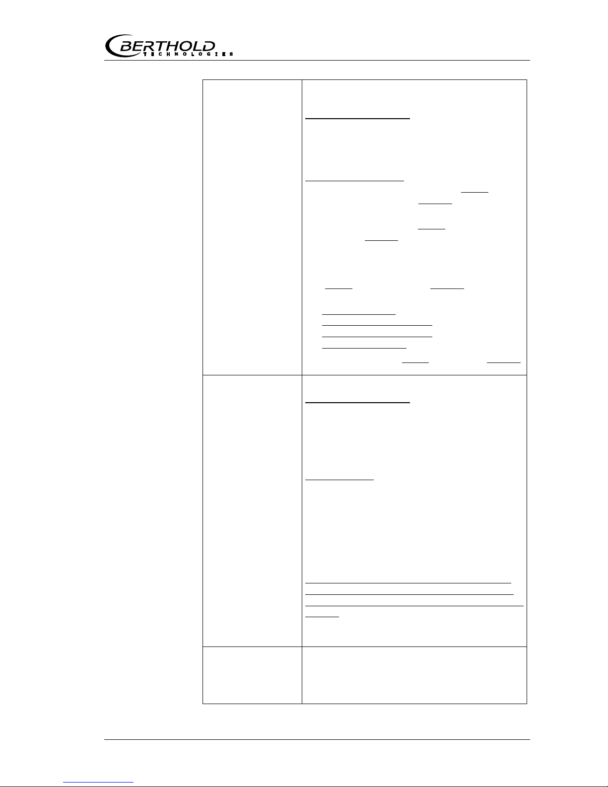
After connection of the PT100 cable, the included ferrite core
must be wound around the cable. The applicable position is
within the housing, as close as possible to the cable bushing.
Digital input 1: DI1 (terminals 24+ and 12-)
Configuration options:
No function
Measurement: Start (closed) and stop (open)
Digital input 2: DI2 (terminals 25+ and 13-)
Configuration options:
No function
Average value: hold (closed) and continue averaging (open)
Product selection: product 1 (open) and product 2 (closed)
Figure 4-8:
PT100 connection
container probe
Figure 4-9:
Ferrite core

Chapter 4. Getting Started
48 MicroPolar (++) LB 566
Digital input 3: DI3 (terminals 26+ and 14-)
Configuration options:
No function
Start sampling, open: no action, closed: unique measure-
ment starts
Product selection
Relay 1: (Terminals 4, 5 and 6) and
Relay 2: (Terminals 16, 17 and 18)
Changeover contacts (SPDT), insulated, configuration option:
No function
Error message
Stop measurement
Limit value min. and max.
No product
Below load limit
RS485 interface (terminals 21 (RS1) and 9 (RS2)) and
RS232 interface (on instrument underside)
Serial data interface for output of the live data (all readings for
every sweep (measuring cycle), the protocol and data logs.
Data format: Data transfer rate 38400 baud, 8 data bits, 1 stop
bit, no parity, no handshake
4.5.2 Digital Outputs, Relay
The status of the measurement is output via two relays:
Error
Alarm (alarm min. and max.)
No product
On the Plausibility menu, you can enter a min. attenuation for
pause detection (e.g. for process pause, no product present); if
this value is not reached, „No product“ is signaled via a relay
and the current output drops to 0 or 4 mA.
Measurement stopped
Below load
The respective switching state is also signaled via LEDs on the
front panel (LEDs signal 1 and 2).

Chapter 4. Getting Started
MicroPolar (++) LB 566 49
Relay no. Error, alarm, no product,
measurement stopped,
Below load, currentless
condition
Normal
1
2
The relays with changeover contacts can either be operated as
make contact, terminals 4 & 5 (open at error, alarm ...) or as
break contact, terminals 5 & 6 (closed at error, alarm ...).
com
456
com
161718
com465com1618
17


Chapter 5. Service instructions
MicroPolar (++) LB 566 51
Service instructionsChapter 5.
5.1 General Information
A malfunction of the measuring system is not always due to a
defect in the instrument. Often the error is caused by incorrect
operation, improper installation or irregularities in the product
being measured. If a malfunction occurs, anyway, the measuring system helps you to identify and eliminate errors by displaying error messages on the display, indicating operator errors
and defects of the electronics.
Defective modules of the evaluation unit cannot usually be repaired but must be replaced. The microwave module is firmly
bolted to a screening hood and must not be opened.
For device disposal, please contact the Berthold Service and apply for a recycling passport.

Chapter 5. Service instructions
52 MicroPolar (++) LB 566
5.2 Wear Parts
The evaluation unit does not include any parts that are subject
to wear or components that require special maintenance.
The plastic caps of the measuring rods of the container probes
and the PEEK Microwave window of the flow cell may be subject
to abrasion over the course of time. A low to medium abrasive
influences the measurement only very little and can be compensated for by a calibration. Therefore, check the wear parts in intervals of about 2 years. In case of heavy wear, the plastic caps
of the measuring rods of the container probe and the PEEK Microwave window of the flow cells can be replaced.
The plastic caps of the measuring rods can be replaced on site.
For this purpose, please proceed as follows:
1
Unscrew the two plastic caps from the measuring rods and
remove the four sealing rings (see figure 5-1, yellow arrow).
2
Clean the four grooves of the sealing rings with a lint-free (if
necessary wet) cloth.
3
For each measuring rod, insert two new sealing rings into
the grooves.
4
Screw on the two new plastic caps.
Caps set for container probe
Id.-Nr. 66049-S 2 pieces of PEEK plastic caps with 4 sealing rings
Figure 4-7:
PT100 connection
container probe

Chapter 5. Service instructions
MicroPolar (++) LB 566 53
5.3 Instrument Cleaning
Clean all system components exclusively with a damp cloth with
no chemical cleaning agent. Parts coming into contact with the
product (during regular operation) can be cleaned with warm
water, taking into account the temperature limits, see chapter
6.2 Technical Data Sensors.
5.4 Battery
If the measuring system LB 566 is a long time without power
supply (power failure or disconnected from the mains supply),
the system clock is powered by the lithium battery on the
motherboard.
If the battery voltage is no longer sufficient, the error message
CODE 14 "Battery voltage" appears after a restart of the evaluation unit. After acknowledging the error message, the unit
continues to work properly; however, the date and time should
be checked and corrected, if necessary. Measurement data that
are output via a serial interface can be fatally damaged by incorrect date and time information. We recommend changing the
batteries immediately.
The service life of the battery, even under continuous stress, is
approximately 8 years. Replacement of batteries must be carried out in a device disconnected from mains.
Battery type: 3 Volt lithium cell (button cell), type CR2032

Chapter 5. Service instructions
54 MicroPolar (++) LB 566
5.5 Fuse Replacement
The mains fuses of the LB 566 are located in the wall housing.
Replace the fuses only if the instrument is disconnected from
mains.
Use only fuses with the correct rating, see chapter 6.1
Spare fuses must match the rating specified by the device
manufacturer. Short-circuiting or manipulation is not permitted.
Figure 5-2:
View with open
housing wall
MicroPolar
0
I
Netzteil
Fuses
Line connector
Terminalstrip
(can be pulled off)
Battery
EEprom
(can be pulled off)
Feed-through for
lineconnector
Testswitch Motherboard
Protectivecover

Chapter 6. Technical Data
MicroPolar (++) LB 566 55
Technical DataChapter 6.
General specifications
Method Microwave transmission measurement
Operating frequen-cy2.4 - 2.5 GHz (ISM band), depending on
local regulations
Transmission
power
MicroPolar: < 0.1 mW (< - 10 dB)
MicroPolar ++: < 10 mW (< 10 dBm)
All coaxial line power
Application Concentration / moisture measurement in
containers and pipelines
6.1 Technical Data Evaluation Unit
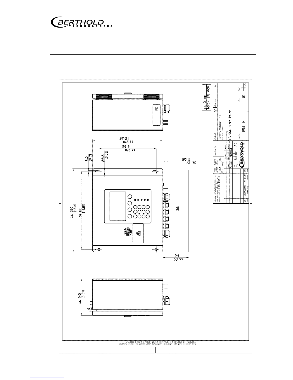
Evaluation unit
Housing Wall housing made of stainless steel, see
dimensional drawing in chapter 8
MicroPolar:
HxWxD: 300 x 323 x 140 mm
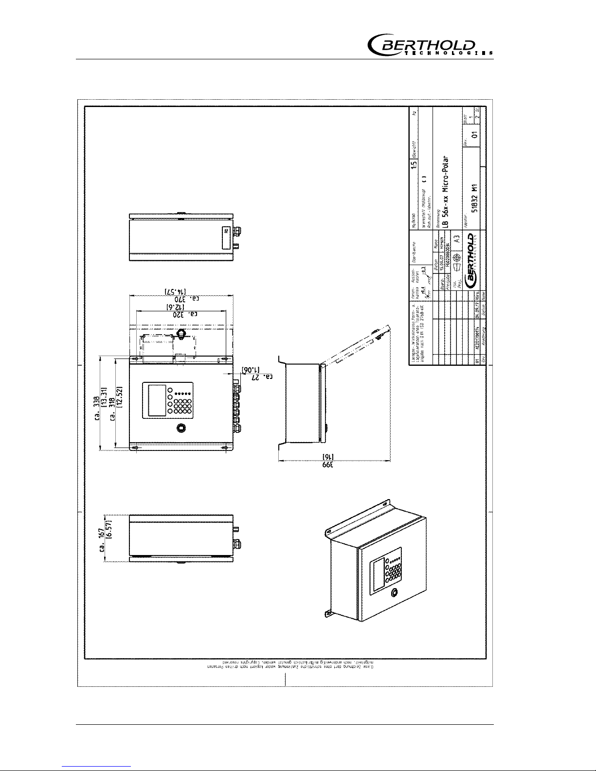
MicroPolar++:
HxWxD: 400 x 338 x 170 mm
Protection type IP 65
Weight MicroPolar: approx. 6.5 kg
MicroPolar ++: approx. 8.0 kg
Ambient conditions
during operation
-20 ... +60 °C ( 253 K ...333 K ),
no condensation
Relative humidity: max. 80 %
Altitude: max. 2000 m
Ambient conditions
during storage
-20 ... +70 °C ( 253 K ...343 K ),
no condensation
Relative humidity: max. 80 %
Achievable
accuracy
0.2 weight % (standard deviation)
depending on product and sensor
Display Dot matrix LC display, 114 mm x 64 mm,
240 x 128 pixels, with back-lighting,
automatic contrast setting
Keyboard Freely accessible foil keypad, light-stable
and weatherproof: alphanumeric key-
board and 4 softkeys (software-assigned
buttons)

Chapter 6. Technical Data
56 MicroPolar (++) LB 566
Power supply For Micro Polar, depending on device type:
1.) 100 ... 240 V AC, 45 ... 65 Hz
2.) 24 V DC: 18...36 V;
24 V AC: -20%, +5%, 40 ... 440 Hz
For MicroPolar++, depending on device type:
1.) 100 ...240 V AC, 45...65 Hz
2.) 24 V DC: 18...36
V, no reverse polarity
protection
Power consumption For Micro Polar:
max. 30 VA (AC/DC), depending on
configuration
For MicroPolar ++:
max. (48/60) VA (AC/DC), depending on
configuration
Fuses For Micro Polar:
2 x 2.0 A / slow-blow
For MicroPolar ++:
2 x 2.0 A / slow-blow at 100 … 240 V AC or
2 x 6.3 A / slow-blow at 24 V DC
Battery type 3 V Lithium button cell, type CR2032
Measured value e.g. concentration, dry matter content
Inputs and outputs
Cable cross-section min. 1.0 mm² (mains supply)
Cable feed-through 2 x M20x1.5 for cable 5...14 mm (depending
on application)
4 x M16x1.5 for cable 5 ...8 mm (depending
on application)
Sensor connection Inputs and outputs for signal and reference
channel, 50 N-socket
HF cable
HF cable
Cable lengths: 2, 4, 6 and 10 m; 50 ; both
sides with 4 N connectors
Current input 2 x current input 0/4 ...20 mA, ohmic
resistance 50 , 1x insulated, 1x instrument
ground
e.g. for temperature compensation
Current output Current output 1: 4...20 mA, ohmic re-
sistance max. 800 , insulated
Current output 2: 0/4...20 mA, ohmic
resistance max. 800 , insulated
e.g. for measured value or temperature
output
PT100 connection Measuring range: -50 ... +200 °C (223 ...
473 K); measurement tolerance: < 0.4 °C
Chapter 6. Technical Data
MicroPolar (++) LB 566 57
Digital input 3 x digital inputs (DI1..3), for floating
connectors
Configuration options:
DI1: none, measurement start/stop
DI2: none, measurement hold, product
selection
DI3: none, sampling, product selection
Function description:
1. Measurement (Start/Stop), open: Measurement stopped, closed:
Measurement
started and/or measurement running
2. Hold measurement, open: measurement
running, closed: measurement stopped,
i.e. average values and current output are
held
3. Product selection via a DI:
open: Product 1 (P1), closed: P2
Product selection via two DI’s:
DI2 & DI3 open: P1
DI2 closed & DI3 open: P2
DI2 open & DI3 closed: P3
DI2 & DI3 closed: P4
4. Start sampling: open: no actions, closed:
single measurement starts
Relay outputs 2 x relays (SPDT), insulated
Configuration options:
- Collective failure message
- Stop measurement
- Limit value (min. and max.)
- No product
- Low load
Load capacity:
AC: max. 400VA
DC: max. 90W
AC/DC: max. 250V, max. 2A, non-inductive
150V: voltage must be grounded
The cable used at the relay output must
correspond to a mains cable.
Restrictions at 24 V AC/DC (DC: 18 ...36 V;
AC: 24 V +5 %, -20 %) mains supply, if the
ground conductor is not connected to terminal
1 (PE):
AC: max. 50 V
DC: max. 70 V
Serial interfaces RS232 on the bottom side
RS485 via terminal strip
Data format: 38400 Bd, no handshake, 8 data
bits, 1 stop bit, no parity
Chapter 6. Technical Data
58 MicroPolar (++) LB 566
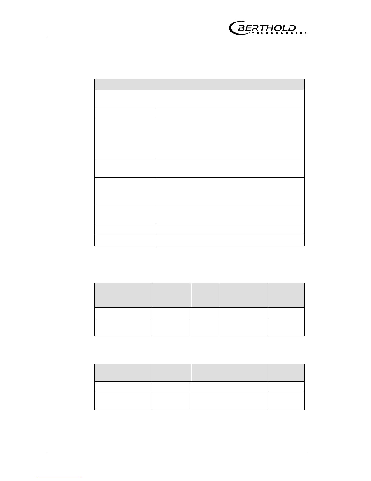
6.2 Technical Data Sensors
Flow cells
Application Microwave FlowCell with various nominal diame-
ters and flanges for measurement on pipelines
Material Stainless steel, PEEK microwave window
Process coupling
Two versions:
1. Hygiene milk pipe screw connection DIN 11853
2. Flange according to EN 1092-1 (V flange)
Optional adapter for the V flange version with
clamp nozzles and ASA flange
Process pressure up to 16 bar (relative), depending on nominal
diameter and flange type, see table below
Temperature range Product temperature: 10...130 °C (283...403 K)
Ambient temperature: -20...60 °C (253...333 K)
Storage temperature: 10...80 °C (283...353 K)
Connections 2 x HF connections: N female, 50
for HF cable with max. 10 m length
Versions Nominal pipe widths from 50 ... 150 mm
Dimensions See dimensional drawings in chapter 8.
Overview FlowCells with V flange
Designation ID no. Nominal
width
[mm]
Flange Pressure
[bar]
LB 5660-102-00x 66744-001 50 DN 50 / PN 16 16
Further versions
on request
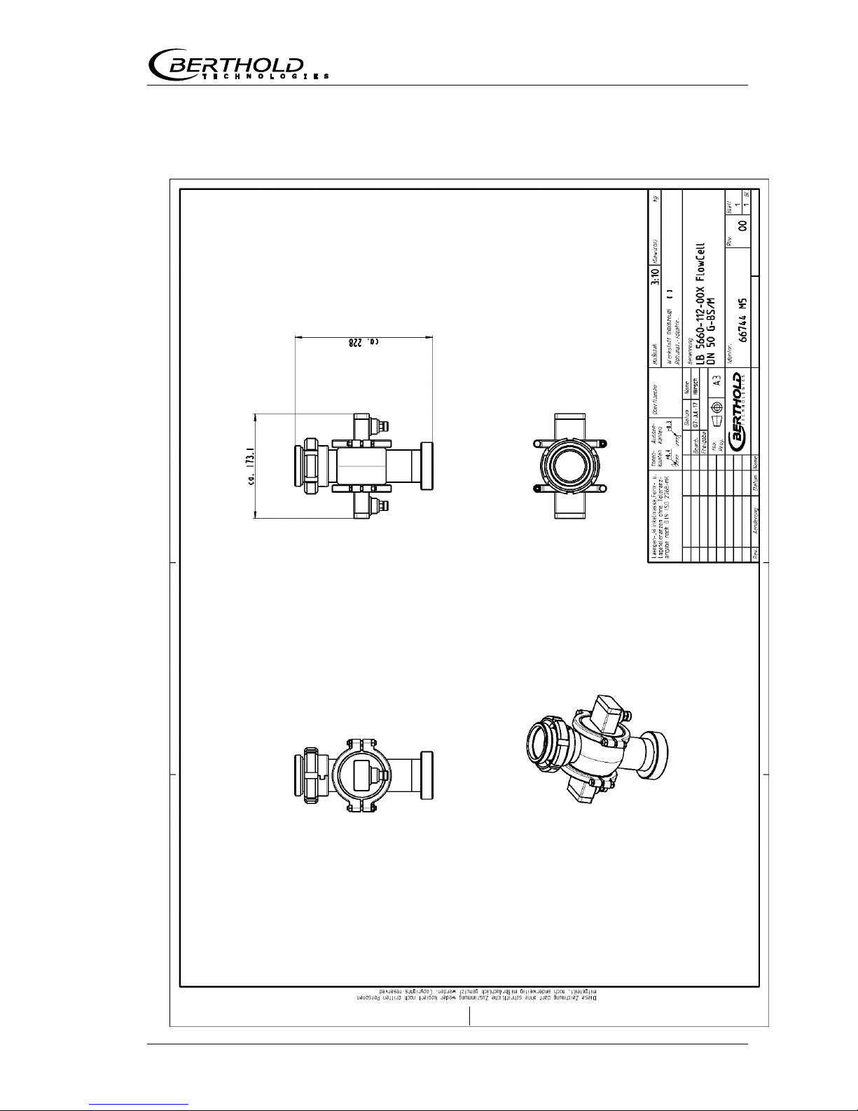
Overview FlowCells with Hygiene milk pipe screw connection
Designation ID no. Nominal width [mm] Pressure
[bar]
LB 5660-112-00x 66744-002 50 16
Further versions
on request

Chapter 6. Technical Data
MicroPolar (++) LB 566 59
Overview ASA flange adapter
Designation
ID no.
ASA flange adapter set for Flow Cell 50 62324
ASA flange adapter set for Flow Cell 65 62319
ASA flange adapter set for Flow Cell 80 62328
ASA flange adapter set for Flow Cell 100 62331
ASA flange adapter set for Flow Cell 150 62335
The kit consists of two adapters, screws and two seals.
Chapter 6. Technical Data
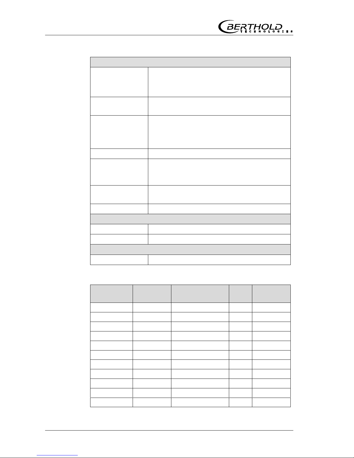
60 MicroPolar (++) LB 566
Container Probes
Application Container probes with and without flushing device
for concentration measurement in process
containers and pipelines with nominal width 200
mm.
Material Plastic caps, stainless steel
PT100 connection cable: Silicon / Teflon
Process coupling Flange according to DIN EN 1092 type 05
DN65 / PN6, DN 80, 100, 150 / PN16;
ASA flange 2.5’’ / 150 PSI
(More on request)
Process pressure Up to 16 bar, depending on model
Temperature range Product temperature: 10...120 °C (283...393 K)
Ambient temperature: -20...60 °C (253...333 K)
Storage temperature: 10...80 °C (283...353 K)
Connections 4 x HF connections: N female, 50
for HF cable with max. 10 m length
Dimensions See dimensional drawings in chapter 8.
Accessory sealing washer
Material Klingersil C-4400
Thickness 3 mm
Caps set for container probe
Id.-Nr. 66049-S 2 pieces of PEEK plastic caps with 4 sealing rings
Overview container probes and sealing washers
Designation ID no. Flange
Pressure
[bar]
ID no.
Seals
LB 5650-01 65464-01 DN 65 / PN6 6 32175
LB 5650-02 65464-02 DN 80 / PN16 16 33717
LB 5650-03 65464-03 DN 100 / PN16 16 46661
LB 5650-04 65464-04 DN 150 / PN16 16 46664
LB 5650-05 65464-05 ASA 2.5’’ / 150 PSI 16 46665
LB 5650-09 65464-09 ASA 3’’ / 150 PSI 16 50659
LB 5651-01 65937-01 DN 65 / PN6 6 32175
LB 5651-02 65937-02 DN 80 / PN16 16 33717
LB 5651-03 65937-03 DN 100 / PN16 16 46661
LB 5651-04 65937-04 DN 150 / PN16 16 46664
LB 5651-05 65937-05 ASA 2.5’’ / 150 PSI 16 46665

Chapter 6. Technical Data
MicroPolar (++) LB 566 61
6.3 Technical Data HF Cable
HF cable Quad
Material Corrugated tube: Polyamide (PA6)
Cable sheath: Polyethylene (PE)
Protection type IP 66
Temperature
In operation: -30 ... +70 °C
When installing: -20 ... +70 °C
Cable length [m] ID no.
2 43431
4 43432
6 43433
8 43434
10 43435
HF cable Quad (solid cable)
Material Cable sheath: Polyethylene (PE)
Protection type IP 68 when unscrewed
Temperature
In operation: -40 ... +85 °C
When installing: -40 ... +85 °C
Attenuation
coefficient
about 0.3 dB/m
Cable length [m] ID no.
2.0 11476
2.5 11477
3.0 11478
3.5 11479
4.0 11480

Chapter 6. Technical Data
62 MicroPolar (++) LB 566
6.4 Format of Serial Data Output RS232 and RS485
Headline
Date·TimeStateStatusSynchronizerProductAttPhiR2TintIN1IN2PT100
CCmC2C2mMF1MF2
Following lines
01.01.2005·00:00:0000000010.435.300.070.00.00.00.0
1 2 3 4 5 6 7 8 9 10 11 12
75.3675.000.000.000.0000.000
13 14 15 16 17 18
Column no. Description Format
1 Date and time DD.MM.YY·HH:MM:SS
2 State 4 digits, HEX
3 Status: Information about the quality of the last
measurement
0 : Measurement OK
< 0 : Error
4 Product synchronization 5: not active
1: still asynchronous
0: all values synchronous
-1: Error
-2: Time too short for syn.
-3: Speed outside range
5 Product number X (1 to 4)
6 Attenuation [dB] X.XX
7 Phase [°/GHz] X.XX
8 Dispersion of the phase regression X.XX
9 Device temperature [temperature unit] X.X
10 Current input 1 [unit of current input] X.X
11 Current input 2 [unit of current input] X.X
12 PT100 temperature [temperature unit] X.X
[…] with selection of the unit g/cm
3
13 Concentration 1 live X.XX [X.XXXX]
14 Concentration 1 averaged X.XX [X.XXXX]
15 Concentration 2 live X.XX [X.XXXX]
16 Concentration 2 averaged X.XX [X.XXXX]
17 Mass flow for concentration 1 X.XXX
18 Mass flow for concentration 2 X.XXX
Special characters
“” Tabulation“¶” Carriage return + Line feed “·” Blank character
Chapter 7. Certificates
MicroPolar (++) LB 566 63
CertificatesChapter 7.
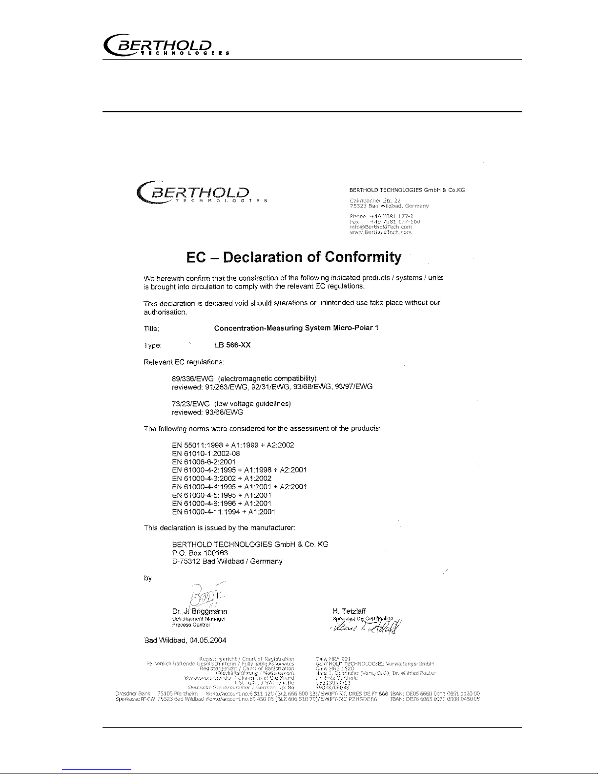
7.1 EC Declaration of Conformity

Chapter 7. Certificates
64 MicroPolar (++) LB 566
Chapter 7. Certificates
MicroPolar (++) LB 566 65
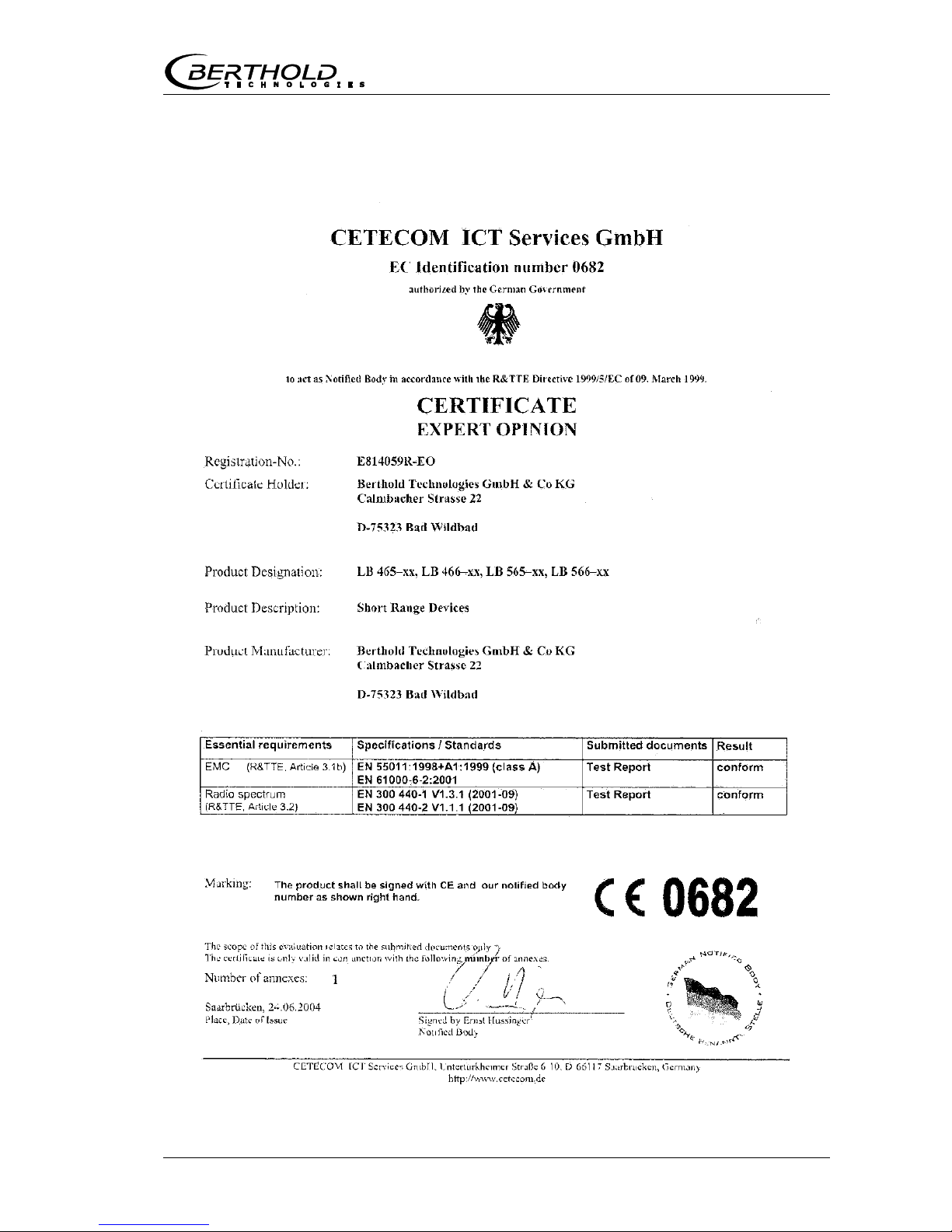
7.2 Frequency License

Chapter 7. Certificates
66 MicroPolar (++) LB 566

Chapter 7. Certificates
MicroPolar (++) LB 566 67

Chapter 7. Certificates
68 MicroPolar (++) LB 566

Chapter 7. Certificates
MicroPolar (++) LB 566 69

Chapter 7. Certificates
70 MicroPolar (++) LB 566
Chapter 7. Certificates
MicroPolar (++) LB 566 71

Chapter 7. Certificates
72 MicroPolar (++) LB 566
Chapter 8. Technical Drawings
MicroPolar (++) LB 566 73
Technical DrawingsChapter 8.
8.1 Dimensions Drawings Evaluation Unit Wall Housing
Chapter 8. Technical Drawings
74 MicroPolar (++) LB 566

Chapter 8. Technical Drawings
MicroPolar (++) LB 566 75
8.2 Electrical Wiring Diagram
Line in for MicroPolar:
1. / 2. depending on
configuration
1.
AC 100-240V, 45-65 Hz
2.
DC 24 V (18-36 V) or
AC 24 V -20/+5%, 40-440 Hz
-------------------------------------------
Line in for MicroPolar ++:
1. / 2. depending on
configuration

Chapter 8. Technical Drawings
76 MicroPolar (++) LB 566
8.3 Dimensional Drawings FlowCell
8.3.1 Type LB 5660-102-00X FlowCell DN 50 VFL. FOA
Chapter 8. Technical Drawings
MicroPolar (++) LB 566 77
8.3.2 Type LB 5660-112-00X FlowCell DN 50 G-BS/M

Chapter 8. Technical Drawings
78 MicroPolar (++) LB 566
8.4 Dimensional Drawings Container Probes
8.4.1 Type LB 5650-01

Chapter 8. Technical Drawings
MicroPolar (++) LB 566 79
8.4.2 Type LB 5650-02

Chapter 8. Technical Drawings
80 MicroPolar (++) LB 566
8.4.3 Type LB 5650-03

Chapter 8. Technical Drawings
MicroPolar (++) LB 566 81
8.4.4 Type LB 5650-04

Chapter 8. Technical Drawings
82 MicroPolar (++) LB 566
8.4.5 Type LB 5650-05

Chapter 8. Technical Drawings
MicroPolar (++) LB 566 83
8.4.6 Type LB 5650-09
Chapter 8. Technical Drawings
84 MicroPolar (++) LB 566
8.4.7 Installation Situation in Pipelines
Chapter 8. Technical Drawings
MicroPolar (++) LB 566 85
8.5 Dimensional Drawings Container Flush Probes
8.5.1 Type LB 5651-01

Chapter 8. Technical Drawings
86 MicroPolar (++) LB 566
8.5.2 Type LB 5651-02
Chapter 8. Technical Drawings
MicroPolar (++) LB 566 87
8.5.3 Type LB 5651-03

Chapter 8. Technical Drawings
88 MicroPolar (++) LB 566
8.5.4 Installation Situation in Pipelines

Index
MicroPolar (++) LB 566 89
Index
A
Accuracy · 55
Adapter flange · 42
ASA flange adapter · 59
Assembly on a container · 33
Assembly on a pipeline · 32
Assembly sheets · 91
B
Battery · 53
C
Cable installation · 39, 43
Calculation of measured values · 18
CE mark · 13
Compatible with foodstuffs · 27
Compensation · 19
Components · 21
Conductive materials · 19
Connector strip · 46
Container probe · 27
Container probe installation · 41
D
Data format RS232 · 62
Data transfer rate · 48
Device disposal · 51
Digital outputs · 48
Distance rail · 38
Distance to metal · 41
E
Evaluation unit · 23
Evaluation unit installation, flow cell · 38
EVU · 15
F
Factory setting · 15
Fitting flange · 41
Flat gasket · 41
Flow cell · 25
Flow cell installation · 36
Flush probe · 15, 29
Flushing parameters · 42
Format RS232 · 62
Frequency license · 12, 65
Fuses · 54
G
Gas inclusions · 14, 36
H
HF cable · 30
HF-cable quad · 30
I
Incrustation · 29
Installation depth · 41
Installation situation in pipelines · 84, 90
Instrument cleaning · 53
L
LED’s · 24, 48
Limitations · 18
M
Mains fuses · 54
O
Overview container probes · 60
Overview flow cells · 58

Index
90 MicroPolar (++) LB 566
Overview sealing washers · 60
P
Pipeline pressure · 36
Power radiation · 14
Power supply · 45
Principle of measurement · 17
R
Recycling passport · 51
Relay · 48
RS232 interface · 48
S
Safety summary · 7
Salt content · 14
Service instructions · 51
Setting up the evaluation unit, container probe · 43
Symbols · 7
Synchronization · 20
T
technical data · 55
Technical data HF cable · 61
Technical data sensors · 58
Technical drawings · 73
Temperature compensation · 19
Throughput calculation · 20
Transmission power · 55
Transport · 35
V
Vertical riser · 36
W
Warning · 7
Wear parts · 52
Wiring diagram · 75

Notes
MicroPolar (++) LB 566 91
Notes
Notes
92 MicroPolar (++) LB 566
Notes
Concentration Meters
MicroPolar (++)
LB 566
User’s Guide
Software Manual
41986BA2
Rev. Nr.: 06-E, 09/2017


MicroPolar (++) LB 566 3
The units supplied should not be repaired by anyone other than Berthold Service engineers or technicians by Berthold.
In case of operation trouble, please address to our central service department (address see below).
The complete user’s guide consists of the hardware manual and the software manual.
The hardware manual comprises the
component description
assembly instructions
electrical installation description
technical data
certificates
dimensional drawings
The software manual comprises the description of the
operation
software functions
calibration
error messages
The present manual is the software description.
Subject to changes without prior notice.
BERTHOLD TECHNOLOGIES GmbH & Co. KG
Calmbacher Str. 22 D-75323 Bad Wildbad
Switchboard: Service:
Phone +49 7081 177 0 Phone +49 7081 177 111
Fax +49 7081 177 100 Fax +79 7081 177 339
industry@Berthold.com Service@Berthold.com
www.Berthold.com

Table of Contents
4 MicroPolar (++) LB 566
Table of Contents
Page
Chapter 1. Safety Summary 7
Chapter 2. Communication with MicroPolar 9
Chapter 3. Getting Started Guide 11
Chapter 4. Software Functions 13
4.1 Information on the Menu Structure 13
4.2 Menu Structure 14
4.2.1 Start Menu 16
4.2.2 Diagnostic 16
4.2.3 Setup 18
4.2.4 Access Level 19
4.2.5 Language 19
4.2.6 Configuration 20
4.2.7 General Data 21
4.2.8 Measurement 21
4.2.9 Plausibility 22
4.2.10 Phase Measurement 23
4.2.11 Offline mode 23
4.2.12 Massflow 24
4.2.13 Calibration 25
4.2.14 System Adjust 25
4.2.15 Calibrate Concentration 26
4.2.16 Sampling 27
4.2.17 Sample Data (expanded) 28
4.2.18 Advanced 28
4.2.19 Calibration 29
4.2.20 Inputs / Outputs 30
4.2.21 Current Output 31
4.2.22 Current Out 1 31
4.2.23 Current Out 2 32
4.2.24 Current input 32
4.2.25 Current Input 1 33
4.2.26 Current Input 2 33
4.2.27 PT100 34
4.2.28 Digital Output 35
4.2.29 Digital Input 35
4.2.30 Service 37
4.3 Trend Display 39
Chapter 5. Configuration 41
5.1 Configuration Setup 41
5.1.1 General Data 41
5.1.2 Measurement 42
5.1.3 Plausibility 42
5.1.4 Microwave 43
5.1.5 Units 43
5.1.6 Marker 44
5.2 Start Calibration Coefficients 45
5.3 Configure Plausibility 46

Table of Contents
MicroPolar (++) LB 566 5
Chapter 6. Calibration 47
6.1 System Adjust 47
6.1.1 Verifying the Reference Values 49
6.2 Sampling 49
6.2.1 Entering the Lab Values 51
6.3 Calibration 52
Chapter 7. Start-up of MicroPolar ++ 53
Chapter 8. Calibration and Advanced 55
8.1 Plausibility | Configuring Phi/Att Ratio 55
8.1.1 Phi/att Ratio 55
8.1.2 Process Recording 56
8.2 Adjusting the Calibration 58
8.3 Output of the Start-up Protocol 60
8.4 Calibration 61
8.4.1 Calibration with Two Concentrations 64
8.4.2 Calibration with Split Value 68
8.5 Typical Calibration Coefficients/Start Values 70
Chapter 9. Password 71
9.1 Password Forgotten 71
Chapter 10. Error Lists and Device States 73
10.1 Hardware and Error Prompts 73
10.2 Input Error 73
10.3 Measurement Error and Error Prompts 74
10.4 Device States 75
Chapter 11. Start-up Protocol 77
11.1 Example of Start-up Protocol 80


Chapter 1. Safety Summary
MicroPolar (++) LB 566 7
Chapter 1. Safety Summary
Please observe all safety instructions in the Hardware Manual, especially those in chapter 1 Safety Summary.
Parameter settings
Never change the installation and the parameter settings without
a full knowledge of these operating instructions, as well as a full
knowledge of the behavior of the connected controller and the
possible influence on the operating process to be controlled.

 Loading...