

Page 1

Potassium Content
Measurement
LB 444 K-40
ID No. 55884BA2
Rev. Nr.: 00
Page 2

Page 3

01/10 347 LB 444 K-40
Operating Manual Potassium Meter
LB 444 K-40
Contents
1 GENERAL INFORMATION ..................................................... 1
2 OVERVIEW........................................................................... 2
3 SYSTEM DESCRIPTION......................................................... 4
4 INSTALLATION OF THE DETECTORS..................................... 5
4.1 Selection of the Measuring Site .............................................................. 5
4.2 Installation of the Detector LB 5430 on a Bunker................................... 6
4.3 Installation of the Detector LB 5402 in a Bunker.................................... 7
4.4 Measurement in a Pipe ........................................................................... 7
4.5 Measurement on a Conveyor Belt ........................................................... 9
4.6 Installation of the Evaluation Electronics ............................................. 10
4.7 Installation of the Detector .................................................................. 10
4.7.1 Installation in a Container .............................................................. 10
5 CONNECTIONS................................................................... 11
5.1.1 Evaluation Unit LB 444 K-40........................................................... 11
5.2 Evaluation Unit LB 444 K-40 ................................................................. 13
5.2.1 General Description....................................................................... 13
5.2.2 Display........................................................................................ 13
5.2.3 Keypad Function........................................................................... 13
5.2.4 Softkeys...................................................................................... 14
5.2.5 Menu Structure............................................................................. 14
5.2.6 Menu Potassium Content Measurement ............................................ 15
6 SOFTWARE FUNCTIONS AND SYSTEM CONFIGURATION ... 19
6.1 General Data......................................................................................... 19
6.2 Operating Mode .................................................................................... 20
6.3 Parameter............................................................................................. 21
6.4 Product Data......................................................................................... 23
6.5 Calibrate...............................................................................................24
6.6 Live Display .......................................................................................... 26
6.7 Service Menu ........................................................................................ 26
7 GETTING STARTED............................................................. 27
7.1 Quick Installation Overview.................................................................. 27
7.2 Getting Started ..................................................................................... 28
7.2.1 Basic Settings............................................................................... 28
7.2.2 Calibration ................................................................................... 29
7.2.3 Checking the Calibration ................................................................ 31
7.3 Live Display .......................................................................................... 31
7.4 Correcting the Results: Addition and Multiplication .............................. 32
7.4.1 Additive Constant.......................................................................... 32
7.4.2 Multiplication Factor ...................................................................... 32
7.5 Automatic Measuring Time Switchover................................................. 33
7.6 Batch Measurement..............................................................................34
7.7 Radiating Interference Detection.......................................................... 35
7.8 Error Messages ..................................................................................... 36
7.8.1 Acknowledging Error Messages ....................................................... 36
I
Page 4

01/10 347 LB 444 K-40
7.8.2 Error Messages during Operation .................................................... 36
7.8.3 Error Messages during Calibration ................................................... 36
7.8.4 Error Messages during Measurement ............................................... 37
7.9 System Start/Stop................................................................................ 39
8 TECHNICAL DATA ...............................................................40
8.1 Evaluation Unit LB 444 K-40................................................................. 40
8.2 Detectors.............................................................................................. 41
9 SERVICE INSTRUCTIONS....................................................42
9.1 General Safety Precautions................................................................... 42
9.2 Evaluation Unit LB 444 K-40................................................................. 42
10 SERVICE.............................................................................44
10.1 Service Menu Overview ........................................................................ 44
10.2 Service Menu ........................................................................................ 46
10.2.1 Plateau Check .............................................................................. 47
10.3 Detector ............................................................................................... 50
10.3.1 Checking the Crystal-Multiplier Assembly ......................................... 50
10.3.2 Testing and replacement of the photomultipliers in the detector LB 543051
10.4 Replacing the Evaluation Unit LB 444 K-40........................................... 52
10.5 Setup Protocol...................................................................................... 53
11 DIMENSIONAL DRAWINGS.................................................55
11.1 LB 5402 ................................................................................................ 55
11.2 LB 5430 ................................................................................................ 55
11.3 LB 444 K-40.......................................................................................... 56
II
Page 5

01/10 347 LB 444 K-40
Operating Manual
Potassium Meter
LB 444 K-40
Issue
No. Date Comments
1 01.01.10 First edition
III
Page 6

Page 7

01/10 347 LB 444 K-40
1 General Information
Safety Summary
Electrical Shock Hazard
Disconnect power to ensure that contact with energized part is avoided during installation
and servicing.
Specific Warnings
Never change the installation or the parameter settings without a full knowledge of the
relevant part of this manual, the connected con troller and the process, if it is controlled
by this measuring device.
1
Page 8

01/10 347 LB 444 K-40
2 Overview
The Potassium Meter LB 444 K-40 is designed for measurements of the concentration of
potassium in bulk materials, suspensions and solutions.
The concentration of potassium in bulk materials or liquid solutions is measured by
detecting gamma radiation of the natural isotope K-40. This isotope is contained in
natural potassium in a constant percentage (0.0119%). As the isotope K-40 decays, it
emits gamma radiation with an energy of 1.46 MeV.
The detector LB 5430 detects radiation using an organic scintillator (PVT), the detector
LB 5402 using a NaI crystal. The radiation triggers tiny flashes of light in the scintillator
which are converted into electrical pulses by the photomultiplier. The count rate of this
radiation is a direct measure for the potassium concentration. In addition , the scintillation
detector responds to radiation emitted from the environment, for example, the walls and
the floor which are covered with a layer of potassium.
Further radiation is generated by incident cosmic rays at the location of the detector.
Background radiation remains more or less constant for each installation within a plant,
provided the location is not changed. To keep the statistical error of the measured result
as small as possible, the scintillation detector, fixed at the outside of a bunker or below a
belt conveyor, is shielded against background radiation by an additional lead shielding.
If the scintillation detector is inserted int o bulk material, solutions or suspensions inside a
protection tube, the material itself is acting as a shielding against the background
radiation.
Potassium can be found predominantly in the form of KCl. However, to this day the unit K2O is
still used in many companies. The evaluation unit LB 444 K40 allows the calibration and
measurement in both units. Important: the calibration and measurement have must be
performed in the same unit. The following details for “K20” also apply for “KCI”.
There is a linear relationship between the count rate measured by the scintillation
detector and the potassium concentration.
This relationship can be expressed as follows:
K = a (N - N
where:
= count rate measured by the scintillation detector if the bulk material or the
N
0
liquid contains 0% K
“N” = count rate detected by the scintillation detector at a concentration “ K” of K
“K” = concentration of K
“a” = reciprocal value of the count rate per % K
* This value can also be understood as the slope of the linear function. The term a x N
is the background expressed as a percentage of K
) (1)
0
O.
2
O.
2
O.
2
O.*
2
0
O.
2
2
Page 9

01/10 347 LB 444 K-40
The hardware and software of the LB 444 K-40 system makes it easy to adapt the
system to rather different measuring geometries and measuring tasks. Therefore, the
settings and parameters of the measuring instrument have to be defined with care for
the respective measuring task when taking the system into operation. Important
parameters may not be changed later, in order not to compromise the reliable operation
of the system. The system should be taken into operation and settings changed only by
persons who know how to work with the instrument. Therefore, all users should read
these operating instructions carefully. We recommend documen t ing all set ting s in a set up
protocol.
Before starting any work, please read this operating manual carefully!
3
Page 10
01/10 347 LB 444 K-40
3 System Description
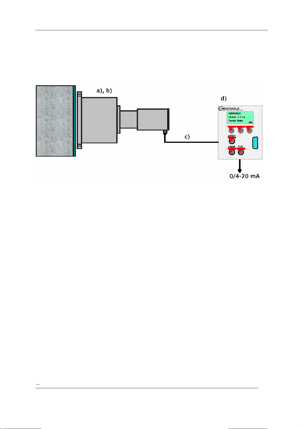
The system is comprised of the following components:
Figure 1: Measuring system with LB 5430 detector
a) Detector LB 5430 for installation on the outside of the container or
b) LB 5402 for installation in a protective pipe inside the container
c) Connection cable
d) Evaluation unit LB 444 K-40
A 19” rack can be supplied for installation of up to 4 devices or a protective hous ing for
two devices for installation of the evaluation unit.
The device LB 444 K-40 with a software that has been expanded for potassium
content measurements is used as evaluation unit. The functions of the density
measurement are still available. This operating manual describes only those
functions that are relevant to the potassium content measurement.
4
Page 11
01/10 347 LB 444 K-40
4 Installation of the Detectors
4.1 Selection of the Measuring Site
Assuming a homogeneous mixture of potassium in the material to be measured, the
number of K-40 isotopes increases with increasing amount of material. This means that
the count rate of the detector rises when the amount of material in front of the detector
rises, although the material contains a constant percentage of the K-40 isotope.
The radiation is partially absorbed between its point of origin and the detector.
Consequently, material that is farther away from the detector does not contribute much
to the result. If the material thickness in front of the detector is increased, or the
detector is surrounded by material, the count rate will rea ch a saturation value and does
not rise anymore even if the thickness of the material layer st ill increases. This material
thickness is called saturation thickness which is expressed as follows:
d = 100/ρ cm,
where ρ is the density of the bulk material in g/cm
Example: For a potassium sample with a bulk weight of 1.2 g/cm
thickness necessary for the measurement would be 100 cm /1.2 = 83 cm.
This means, for a surface probe, the inner diameter of a bunker should be
about 83 cm; a dip probe should be inserted in the center of a bunker having
an inner diameter of at least 166 cm.
These conditions ensure that the measured value is independent of bulk density
variations.
If this conditions cannot be fulfilled, one has to
calculate if the errors that occur as a result of a
smaller volume and a possible change of the bulk
weight or the density are still acceptable.
The goal of a continuous measurement of the K
content is to cover the detection device with the total
amount of material to be measured, i.e. the position
of the scintillation detector has to be selected such
that the surrounding material thickness is not much
thicker than the saturation thickness.
If this is not the case the material being further away
from the detector than the saturation thickness would
not contribute to the measurement and therefore its
potassium content would not be taken into account
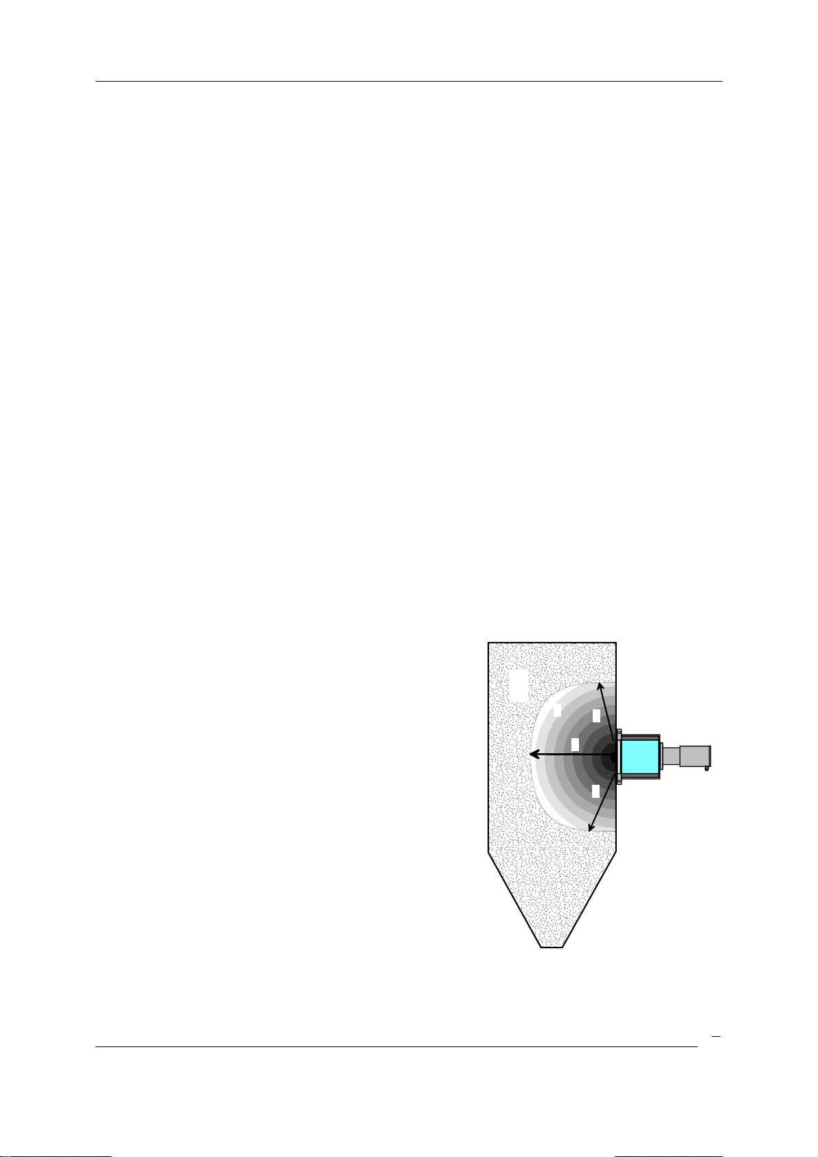
(see Figure 2).
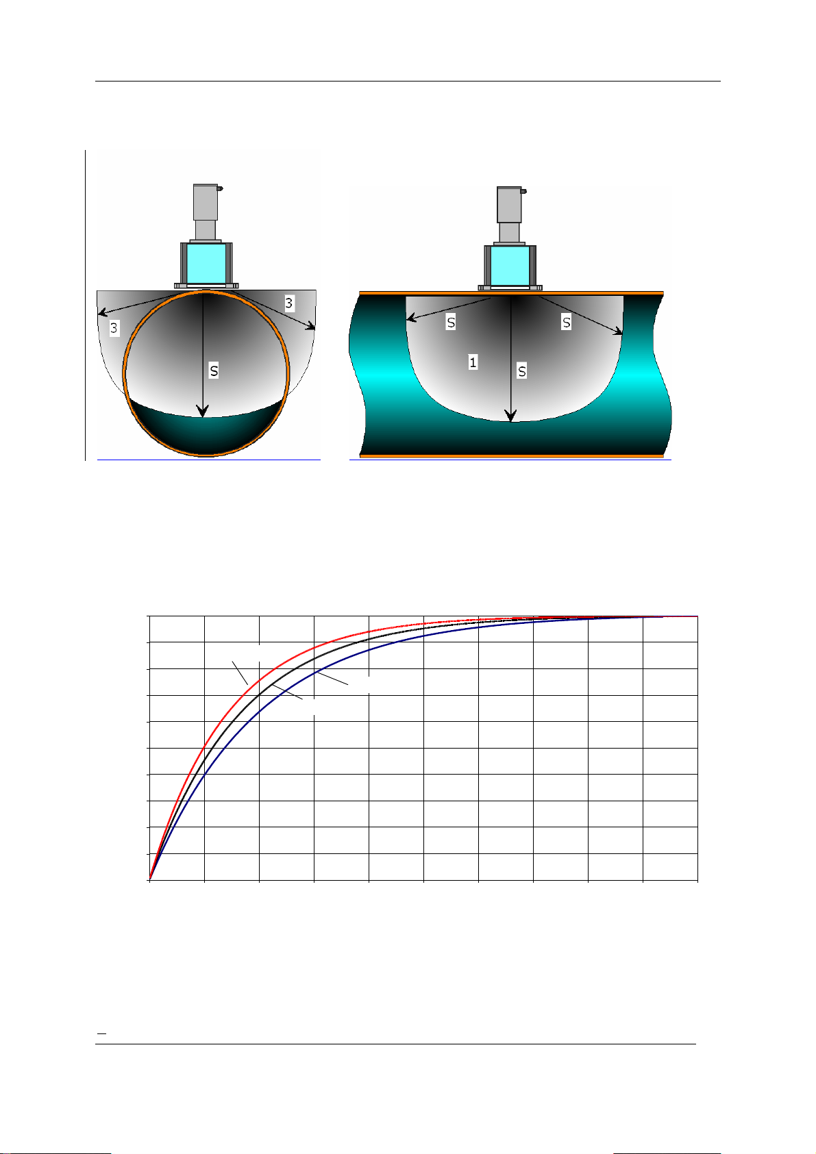
Provided the product to be measured shows a
homogeneous structure, no measurement errors will
occur.
3
.
3
the saturation
2
1
S
0
2
S
S
S = saturation layer thickness
1 = measured material layer
Figure 2: Saturation layer
5
Page 12
01/10 347 LB 444 K-40
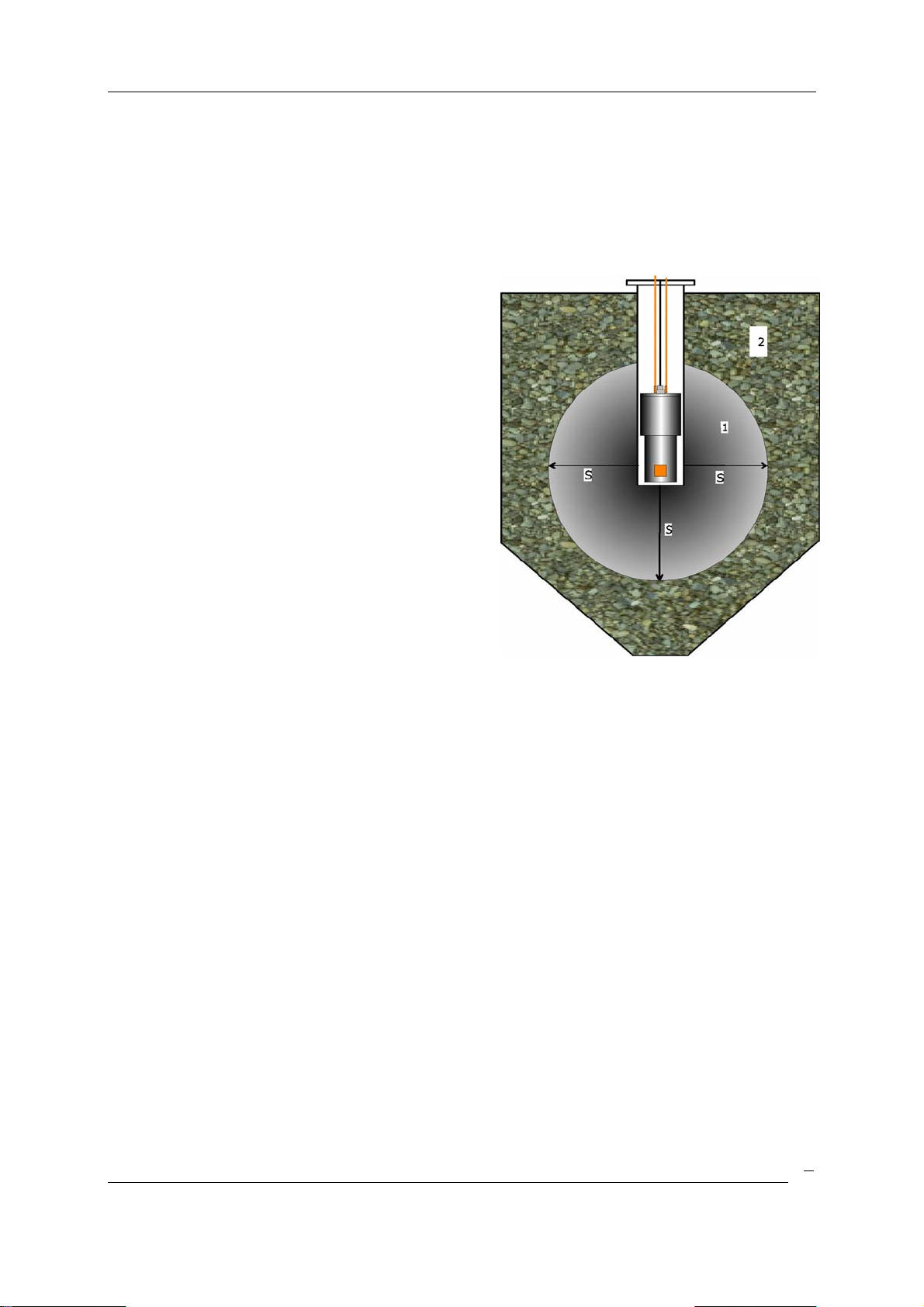
2 = material not covered by the measurement
4.2 Installation of the Detector LB 5430 on a Bunker
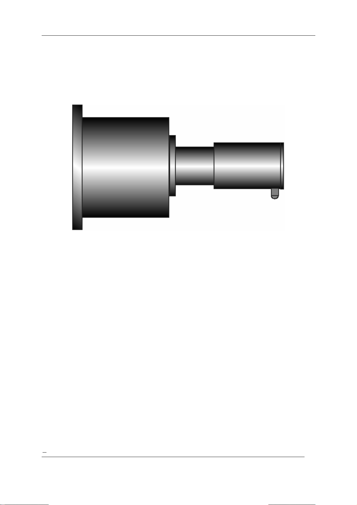
The LB 5430 detector is installed on the outside wall of a bunker. Typically, it is fixed to
the flange of the detector.
Figure 3: Detector LB 5430
Depending on the version, the detector weights approx. 60 – 70 kg. Please take this
weight into account in your planning.
All screws and mounting parts have to be secured such that they cannot come loose
during operation, so that the detector cannot fall down.
The detector must not be subject to heavy mechanical vibrations. If extreme vibrations
are likely to occur at the installation site, the detector has to be mounted on a damping
and shock absorbing arrangement.
Care must be taken that no potassium containing material may be deposited between the
surface probe and the outside wall. This would result in measurement errors.
The ambient temperature at the installation site of the detector must not exceed 50°C. If
the bunker wall is hot (>50°C), you may insert a suitable insulating plate having a
thickness of approx. 20 mm between the container wall and the detector or use a
detector with water cooling.
6
Page 13
01/10 347 LB 444 K-40
4.3 Installation of the Detector LB 5402 in a Bunker
The detector is installed into a protective pipe, front side closed, and inserted into a
bunker. The distance of the material surface in front of the detector head sensitive to
radiation (position of the scintillation crystal) should on all sides correspond to the
calculated saturation thickness.
If hot liquids are used a cooling water jacket for
the probe is necessary.
The detector temperature must never
exceed 50°C.
No crystallization must occur on the protective
pipe. If necessary, the protective pipe has to be
provided with a thermal insulation and possibly
with a heating jacket.
Crystallizations would significantly falsify the
measured results, since the potassium
concentration in the crystallized layer is
typically higher than in the liquid solution.
S = saturation layer thickness
1 = measured material layer
2 = material not covered by the measurement
Figure 4: Measurement in a container
4.4 Measurement in a Pipe
When measuring in a pipe, the saturation layer thickness is usually n ot achieved or at
least not achieved in all directions. In the case of large pipes, the saturation layer
thickness is usually achieved in the longitudinal direction of the pipeline, However,
transverse to the pipeline axis, the saturation layer is not always achieved. This can have
an effect on the measurement result, which is larger:
a) the smaller the pipe is
b) the stronger the density varies in the pipeline, (see Figure 6).
The measurement of the saturation thickness is also affected by the diameter of the pipe,
the pipe material and the wall thickness of the pipe.
A correction of the influence is possible in some cases by an additional density
measurement.
This will require an extended period of time for the recording of
a) Density values
b) Displayed K2O values and
c) the appropriate, K2O values determined in the laboratory.
7
Page 14
01/10 347 LB 444 K-40
A correction function can then be calculated from these values.
Figure 5: Measurement in a pipeline
Potassium measurement. Saturation thickness for different densites resp.
bulk densities
100
90
80
70
60
50
cps in %
40
30
20
10
0
0 100 200 300 400 500 600 700 800 900 1000
Density =1,4
Density =1,0
Density =1,2
Layer thickness in mm
Figure 6: Influence of thickness and
density
Installation:
8
Page 15

01/10 347 LB 444 K-40
The detector should be mounted in a horizontal pipeline at the top or side. This will
prevent that the measurement is influenced by any deposits on the ground of the
pipeline.
4.5 Measurement on a Conveyor Belt
Normally, the required saturation thickness cannot be reached on a conveyor belt, so the
measured result will be influenced by changes of t he bulk weight and/or changes of the
material layer thickness.
However, if it is ensured that
• variations of the bulk weight in the material cannot occur (uniform grain size)
• the height of the material layer is kept constant by leveling device.
a measurement can also be carried out on a conveyor belt. However, the measurement
error is larger than with measurements in a bunker.
9
Page 16
01/10 347 LB 444 K-40
4.6 Installation of the Evaluation Electronics
The evaluation unit (protection type IP 20) can be installed in a 19” rack. This rack then
has to be installed into a suitable measurement cabinet.
The wall housing can be fixed directly to a wall using screws. For outdoor installation, you
may have to install a sunshield to protect the evaluation unit against solar heating.
4.7 Installation of the Detector
Use a water cooling jacket to protect the detector against temperatures > 50°C.
Cables have to be protected against temperatures > 70°C.
Measuring system installed outdoors have to be protected from rain and direct sunshine
by a canopy. The cable entry must not be exposed to temperatures exceeding 70°C. The
cable gland and the cable entry must be aligned such that no water can flow along the
cable into the connection box.
The detector installation site must not be subject to heavy vibrations as this could
damage the detector.
Samples have to be taken for calibration of the measurement. A sampling point
foreseen in the direct vicinity of the measuring site.
has to be
4.7.1 Installation in a Container
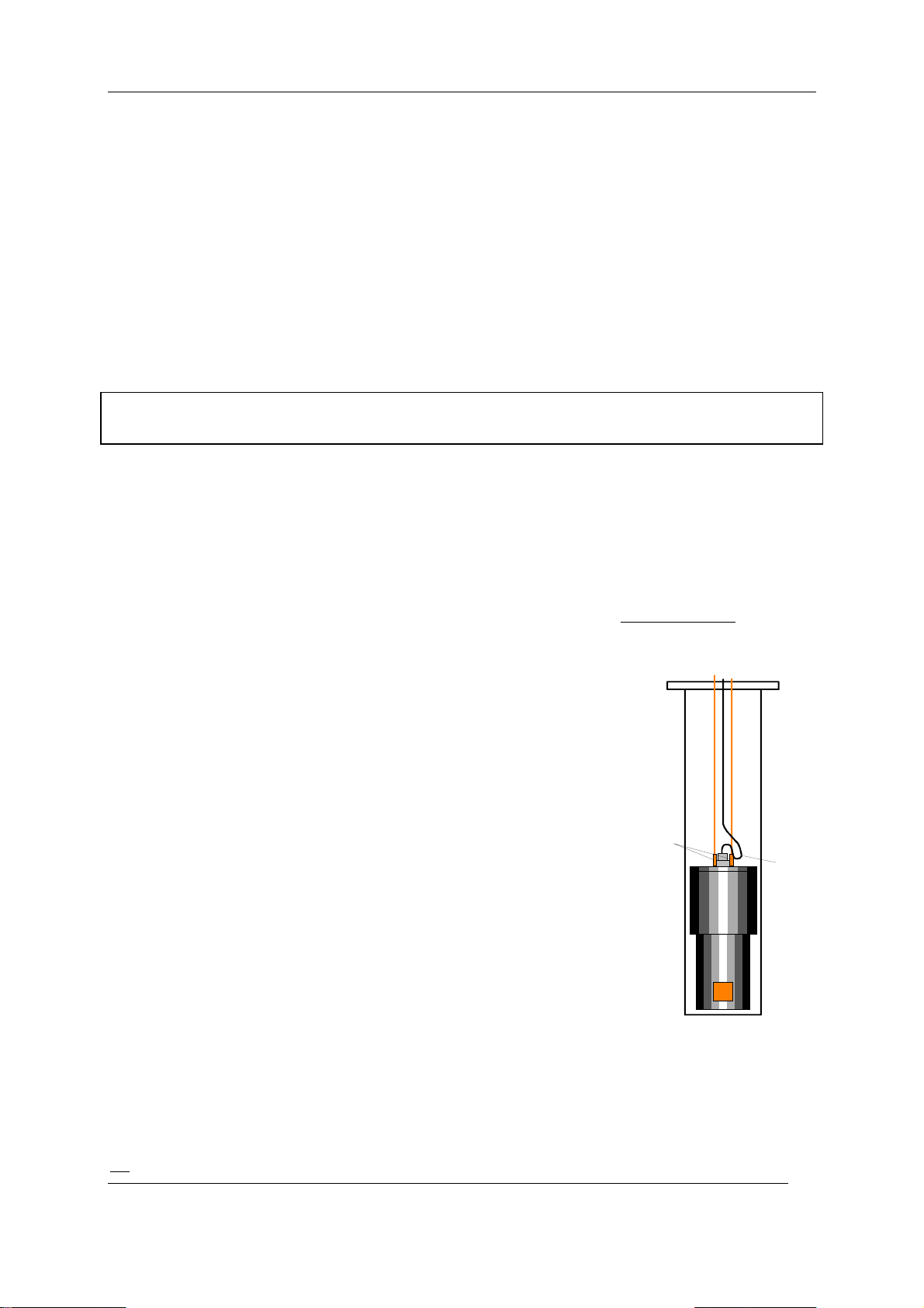
If the detector is installed in a protective pipe inside the
container, the protective pipe has to be sealed to prevent
the penetration of dust and humidity. The detector
includes two suspension eyes. Wire ropes can be attached
to these suspension eyes. It is not permitted to suspend
the detector on the cable.
The cable should form a loop to allow possibly penetrating
water to drip off.
Suspension
eyes
Figure 7: Installation of detector in a protective pipe
Loop
10
Page 17
01/10 347 LB 444 K-40
5 Connections
The power supply of the detector and the transfer of the measured values and important
information to the evaluation unit LB 444 K-40 takes place via a two-wire screened cable.
The possible cable length is dependent on the cross-section of the connection cable used.
The cable entry at the detector
permits a cable diameter of 6-10
mm.
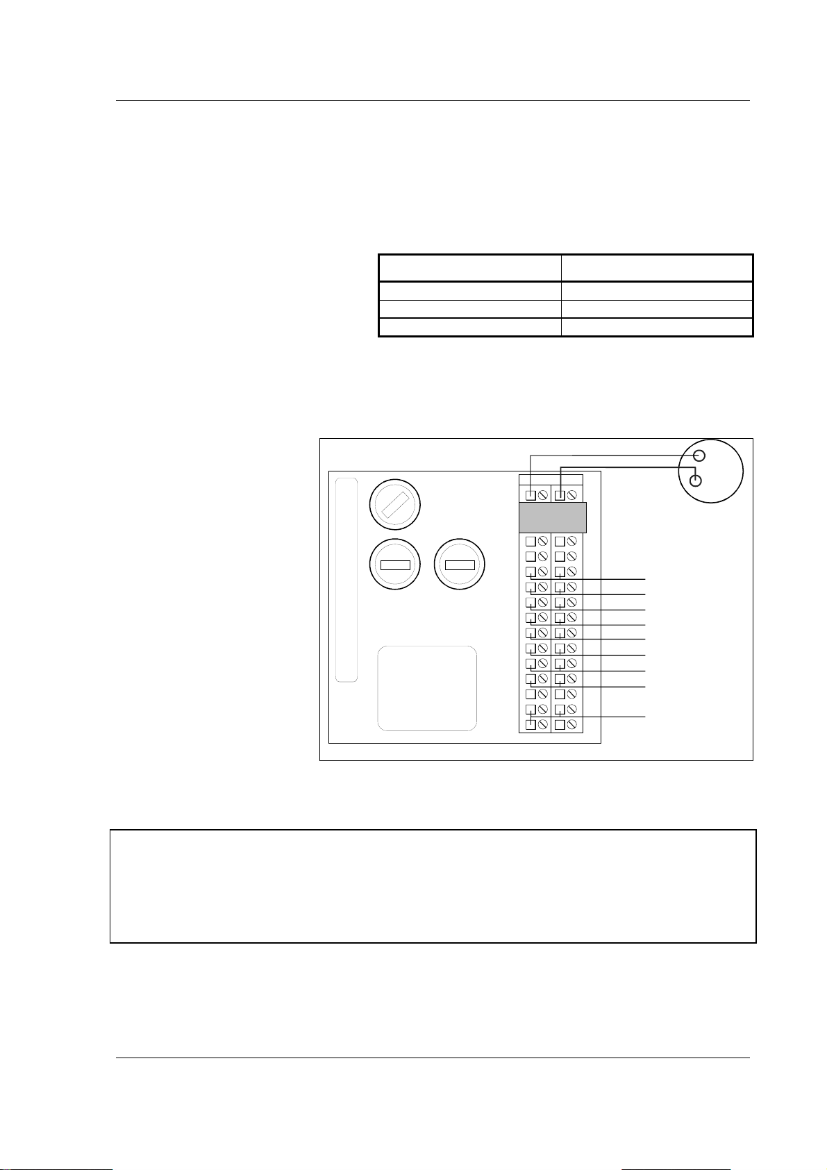
5.1.1 Evaluation Unit LB 444 K-40
Connect cable on the
rear panel of the
evaluation unit as shown
in the wiring diagram in
the appendix to this
manual.
LB 444
cross-section in mm² Max. cable length in m
1 1000
1.5 1500
2.5 2500
Probe
2
1
Fuses
Voltage
selection
2(-) 1 (+)
c a
2
4
4
6
Distanzpart
6
8
8
10
12
14
16
18
20
22
24
26
28
30
32
Relay 2
Relay 3
Relay 1
Dig. IN 1
Dig. IN 2
Dig. IN 3
RS 485
0/4 - 20 mA
Mains
Figure 8: Terminal connection evaluation unit (rear panel)
Connect the device only to the appropriate line voltage.
All safety previsions regarding the power distributor have to be observed.
The evaluation units do not include a separate mains switch. A separate
safeguarding and easily accessible shut-down have to be foreseen.
The device must not be installed in explosive hazardous areas.
Refer to the wiring diagram in the appendix to this manual regarding the connections.
11
Page 18

01/10 347 LB 444 K-40
Detector (2a/2c)
Relay 2 (12a/12c)
The relay can be set for the following functions:
Min. – Alarm, Max. – Alarm, Detector temperature,
Relay 3 (4a/14c)
Functions:
Min. – Alarm, Max. – Alarm, Detector temperature,
Relay 1 (16a/16c)
The relay is used to indicate errors. The contact opens in case of error.
External product selection
Digital input 1 (18a/18c)
Digital input 2 (20a/20c)
Calibration data of up to 4 different products can be defined in the evaluation unit LB 444
K-40. These data sets can be selected via digital inputs.
External Start/Stop Signal (22a/22c)
Option to interrupt measurement for the following special applications:
- Start/Stop in batch mode
- Stop of continuous measurement, e.g. to suppress unexpected malfunctions
0/4-20mA (26a+/26c-)
Isolated current output for measured value, max. load 500 Ω.
Current input (28a-/28c+)
Product temperature for temperature compensation (usually not needed for potassium
content measurements).
Power supply (30a/30c)
Power supply 115V/230V AC or 24 V AC/DC depending on power supply unit (see
label on instrument rear pane!).
Fuses
To replace fuses, you have to open the fuse holder with a screw-driver. Observe fuse
type and rating!
Before turning on the power supply, carefully check all conn ections once more to rule out
any damage to the instruments.
RS 232
Port for data transfer from evaluation unit to printer or PC (front panel of evaluation
unit).
12
Page 19
01/10 347 LB 444 K-40
5.2 Evaluation Unit LB 444 K-40
5.2.1 General Description
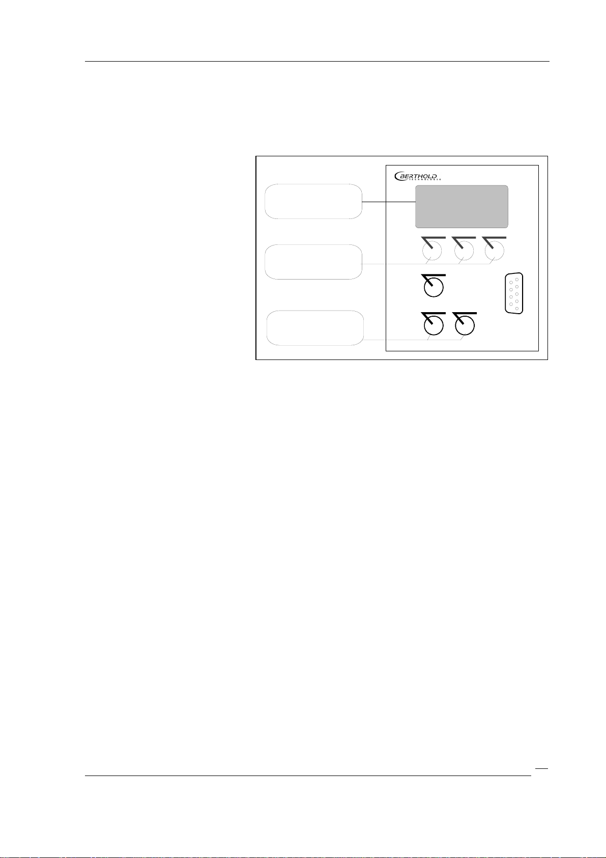
The evaluation electronics is
designed as a 19” module in
the format 3 HE, 21 TE. It
includes the microprocessorcontrolled evaluation electronics and the power supply
for the required operating
voltage. A 32 bit microprocessor is used for signal
processing.
LCD displa y
Function keys
Softkeys
BERTHOLD
LB 444 - 1 V 1.0
Density -Meter
enter
enter
clear
run
enter enter
clear run
more
Figure 9: Operating elements of the evaluation unit
The instrument is operated via six foil keys:
Three keys work as softkeys which allow user-guided definition of all instrument settings
and input of the required parameters.
Three more keys serve as function keys.
The front panel includes a RS 232 interface port. Data can be transferred to a PC using a
terminal program.
The terminal strip on the instrument rear panel includes all terminals for power supply,
for the detector, and for the analog and digital output signals. The current output is
isolated. The built-in relays for max.-min.-indication an d for error messages include an
isolated contact.
System malfunctions are signaled by error messages.
Calibration data is stored in a FLASH memory and saved, so they will n ot be lost in case
of power failure.
5.2.2 Display
The instrument’s illuminated display compri ses four lines. The first three lines show the
menu titles, the currently selected parameters or the current measurement value. The
bottom line shows the current function of the respective softkey button. If a measurement is running, the “run” status is displayed.
5.2.3 Keypad Function
The Potassium Meter is operated via the softkeys and function keys described below.
With these keys you can select the operating level you want within a menu structure in
order to select a function or enter parameters.
13
Page 20
01/10 347 LB 444 K-40
T
5.2.4 Softkeys
Softkeys are used to select different menu grou ps and operating levels within the menu
structure. Depending on the current position in the menu structure, functions are
assigned to these keys, as shown on the display above the respective key.
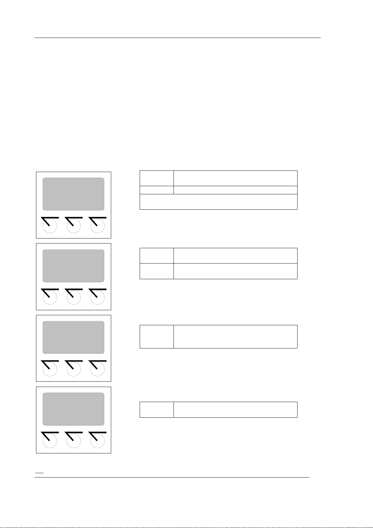
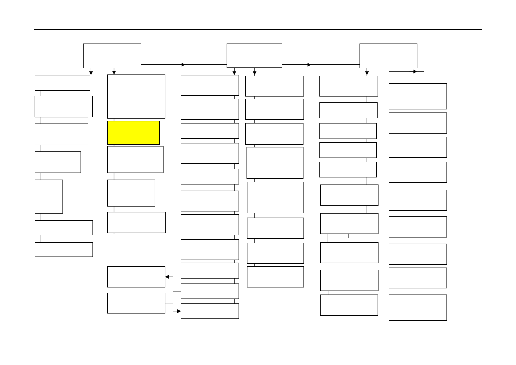
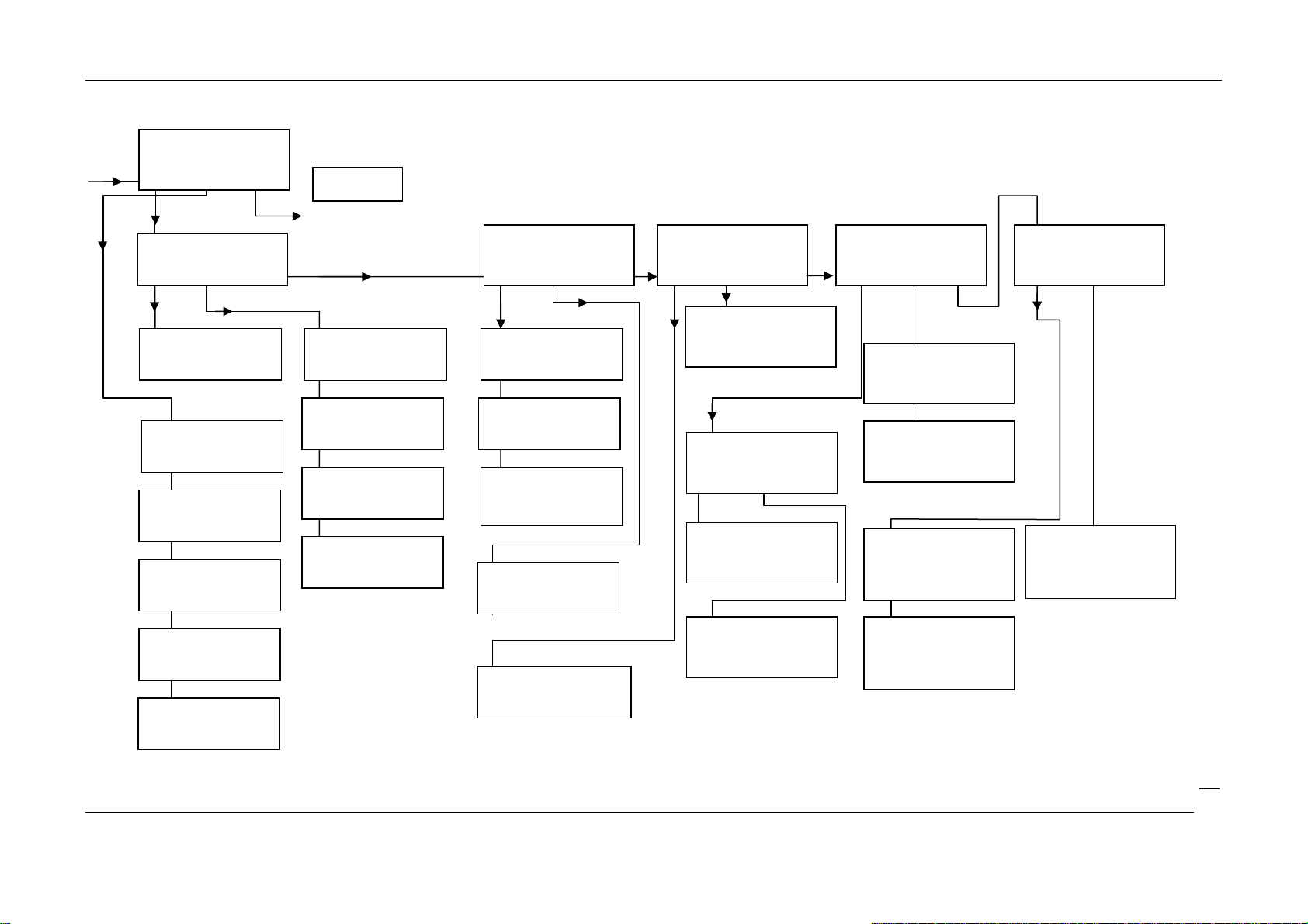
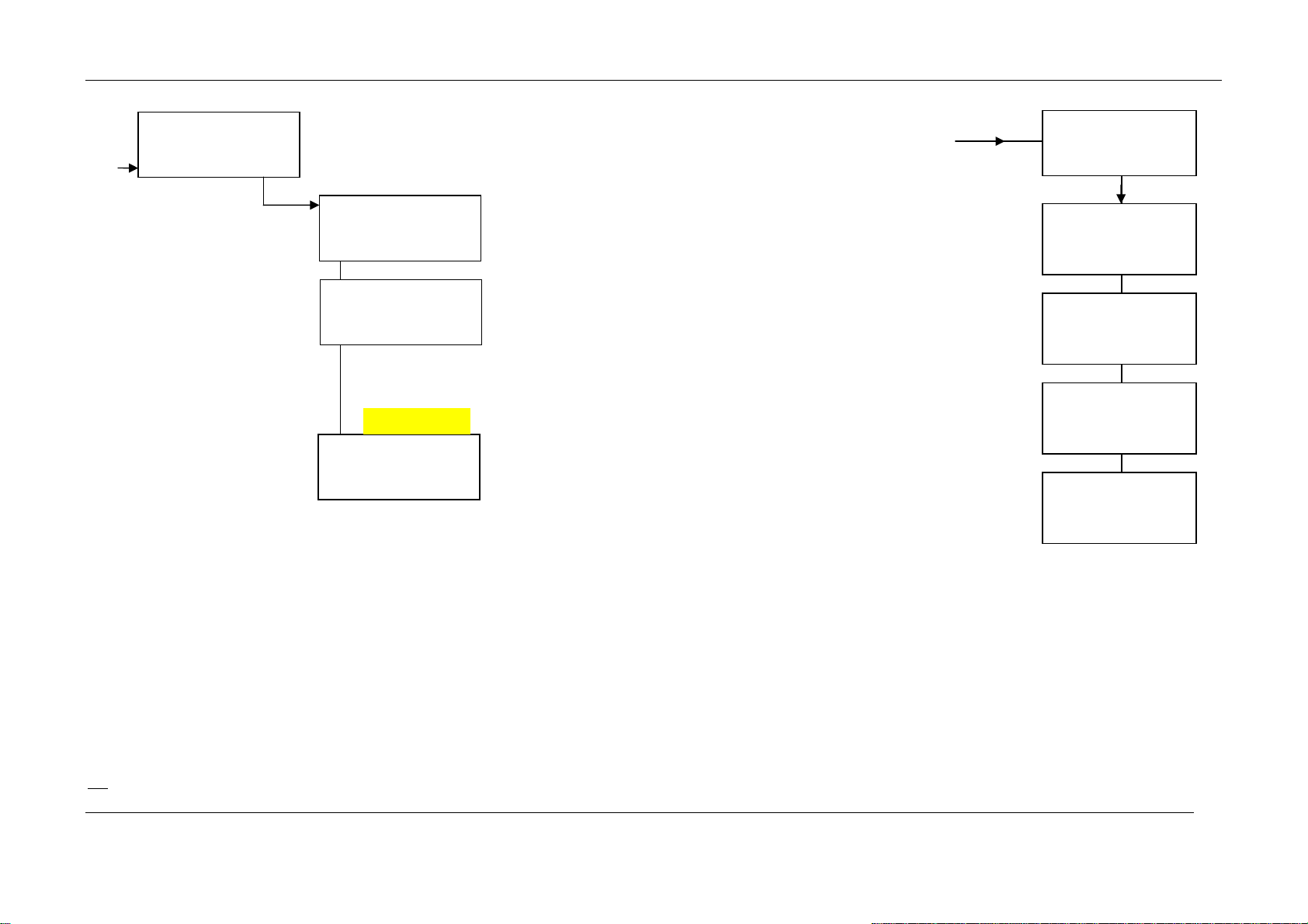
5.2.5 Menu Structure
The menu structure is illustrated on the following pages. Push <more> to select the
various menu groups. From there you get to the respective menu by pushing <sk1> or
<sk2>. Within the menu, push <more> to go to the individual windows and at the end
of the menu push <done> to return to the menu group.
sk1: General Data
sk2: Operating Mode
sk1 sk2 more
Relay 2
Minimum 50%
Hysteresis 5%
^^^
<-<-<-
Time constant
Value 20s
^^^ <-<-<- more
HV (500): 20/s
HV (560): 123/s
HV (560): 620/s
+ - exit
more
sk1 and
sk2
more Go to next display or menu group
done Shows the end of the menu and
^^^
Numerical values: increments the
+ and -
Go to the indicated menu
takes you back to the menu group
ext: scrolls through the various
selection options
number marked by the cursor by 1
Moves the cursor to the left and at
the end of the input field again to the
start position
Scrolls forward / back in a result list
or in the live display
Figure 10: Softkey functions
14
Page 21
01/10 347 LB 444 K-40
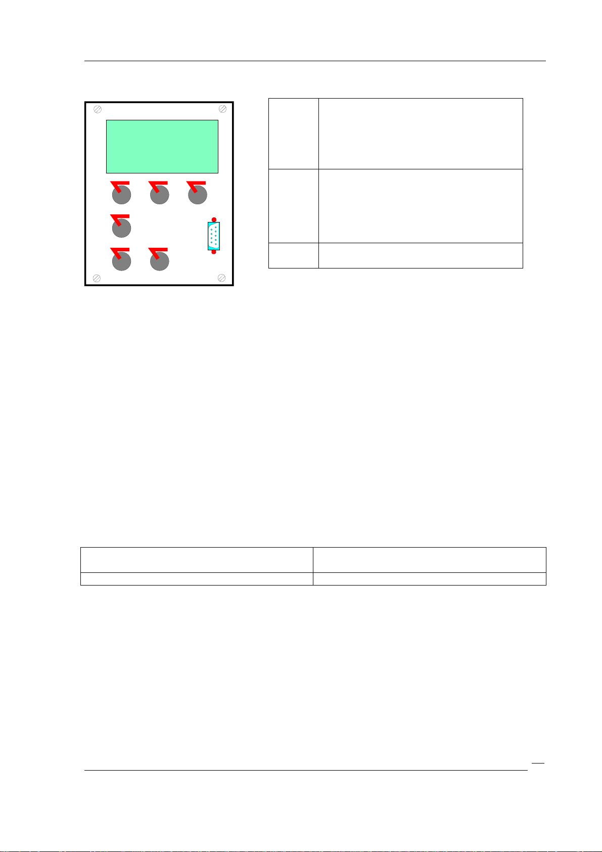
Enter Accepts the entry and moves the
cursor to the next input field or
sk1 : General Data
sk2 : Operating Mode
sk1 sk2 more
enter
clear run
Figure 11: Function keys
Run Starts or stops a measurement or
Clear
toggles between two input fields.
leads directly back to the display and
at the start of a measurement
automatically changes to the
measurement value display.
Clears the numerical value.
5.2.6 Menu Potassium Content Measurement
Select the menu item
Operation mode more K20 ENTER
to automatically select the parameters that are relevant for the potassium content
measurement:
• linear characteristic
• time constant 300 s
• measuring path “1”
• no decay compensation
In addition, the detector code has to be checked and changed, if necessary.
Detector LB 5430 with organic scintillator
(PVT)
Detector LB 5402 with NaI scintillator Detector code 0
Detector code 23
15
Page 22
01/10 347 LB 444 K-40
Password: xxxx
Date & Time
Date : 01.02.00
Time : 12.21
Berthold
LB 444 K-40 V. X.XX
Density - Meter
Berthold
Detector Software
Version 1.02
Language
Deutsch
English
Francais
Espanol
Print Parameter?
(press Enter)
sk1: General Data
sk2: Operating Mode
sk1 sk2 more
Config instrument
Density without TK
Density with cur. Inp
Mass Flow without TC
Mass Flow with Pt 100
Radiation measure
Backscatter measure
K20/KCl
Error mode
in error case
stop measurement/
continue measurement
Relay in error case
Hold state
Current following
Current outp. error
current: HOLD / VALUE
Value: 12 mA
sk1: Parameter
sk2: Product Data
sk1 sk2 more
Measuring product
No.: 1/2/3/4
Product 1
Detector und Isotope
Code: 0
Isotope: Cs 137
Measuring Path
Value : 10,0 cm
Select: Measure Mode
Continuous Measure
Batchmode
Time constant
Value: 10.0s
Rapid switchover
OFF / ON
Sigma: 3,0000
Radiating inter
ference OFF/ ON
Sigma: 5.0000
Product select
Nr.: 1/2/3/4
Product 1
Current Output
Range : 4 - 20 mA/
0 - 20 mA
Curr. Output Limits
0/4 mA 1,0000
20 mA 1,2000
Relais Nr. 2 setup
Minimum
Maximum
Det. Temp
Hysteresis : 5%
Relais Nr. 3 setup
Minimum
Maximum
Det. Temp
Hysterese : 5%
Temperature coeff.
TC 1
Value : 1.2345e-03
Product select
Nr.: 1/2/3/4
Product 1
Suspensions measure
yes / no
Solid density
Value: 2.6500 g/cm3
Liquid density
Value: 1.0000 g/cm3
Water TC ?
yes / No
Unit select
[g/cm2] [Bx] [Be] [g/]
Unit : g/cm3
sk1:Data input
sk2:Calculate
sk1 sk2 more
sk1:Calibrate
sk2:Live Display
sk1 sk2 more
Calibrate mode
one / lin / squ / cub /
auto
Mode: linear
Zero countrate Io
Value: 54321 cps
Coefficient a1
Value: - 6.64000e - 02
Coefficient a2
Value: - 1.23400e - 04
Coefficient a3
Value: - 1.23456e - 06
Square Error
Value: 0.000000
16
Factory setting
Current input:
Range: 0 - 20 mA
4 - 20 mA
Temp. Input
0 / 4 mA: 0 °C
20 mA: 10 0 °C
Radiating inter
ference:-:
Delay time: : 20 s
Maximum Rate:
Value: : 100000 cps
Minimum Rate:
Value: : 0 cps
Product selection
extern / intern
Temperature coeff.
TC 2
Value : 1.2345e-06
Reference
Temperature
Value : 30 °C
Calibr. Data transfer
yes / no
Product 1->2 ?
1. Rate = 12345 cps
1. 1.0000 g/cm3
1. Temp. = 44,2 °C
10. Rate = 12345 cps
10. 1.0000 g/cm3
10. Temp. = 44,2 °C
Factor
Value: 1.0000
Offset
Value: 0.0000
Calibration value
1. 1.0000 g/cm3
2. 1.1200 g/cm3
+ -
Page 23
01/10 347 LB 444 K-40
sk1: Service Menu
sk2: Mass Flow
sk1 sk2
Page 16
sk1: Test calculate
sk2: I / O - Test
sk1 sk2 more
Testrate 12345 cps
Output Curr : 10,0 mA
1,2345 g/cm3
Unit Mass Flow
[kg/h, t/h]
t/h
Range input
{at 20 mA]
Value: 100 m3/h
Flow
Value 87.00 m3/h
Ext. Mass
Counter
Tons per cycle
Erase mass integrator
no/ yes
Set outputcur
Current : 9.0mA
View input cur.
Current: 12.0mA
Relay 1 : ON
Relay 2 : OFF
Relay 1 : ON
Input 1: OFF
Input 2: OFF
Input 3: ON
sk1: HV Adjustment
sk2: Status request
sk1 sk2 more
High Voltage
Value : 800 V
Save Default
Value : 850 V
Read Default
Value : 850 V
Temperature =
45.2°C
Det. Temp. = 28 °C
For Detector - Reset
please press (sk 1 &
clear)
sk1: Reset Detector
sk2: Pt 100 adjust
sk1 sk2 more
For Pt 100-Adjust
please press
sk1: Measure Plateau
sk2: Request Plateau
sk1 sk2
Plateau measurement
running......
IIIIIIIII...........................
HV( 500): 817/s
HV( 560): 884 /s
HV( 620): 923/s
+ - done
sk1: Plateau
sk 2: Adj. Current out
sk 1 sk2 more
Current 1.8 mA
Offset: 4123
-
Current 18 mA
Offset: 345
-
Curr. Input Adjust
Set value 1.8 mA
Real value 1,7 mA
+ - more
Curr. Input Adjust
Set value 18 mA
Real value 17.5 mA
+ - more
sk1: Adj. Cur. input
sk 2: Relay Delaytime
sk 1 sk2 more
Relay delay
Value: 50 ms
17
Page 24
01/10 347 LB 444 K-40
sk1: Service Menu
sk2: Mass Flow
sk1 sk2 more
sk1: Interface
sk1 more
Interface
RS 232: Printer/PC
RS 485 Printer/LB 447
sk1 more
sk1:Calibrate
sk2:Live Display
sk1 sk2 more
L B 4 4 4
DENSITY
1.2345 g/cm3
+ -
Value: 1.2345 g/cm3
Temperature: 45.2 °C
1.2345 g/cm3
+ -
RS232 PC only
PC Access Control
Read only data /
change of data
I-mean = 12345 cps
I-actual = 12435 cps
HV -auto = 745 V
+ - more
Detector
Temperature: 47 °C
+ - more
18
Page 25

01/10 347 LB 444 K-40
6 Software Functions and System
Configuration
Depending on the selected configuration, some input dialog boxes are dimmed. In
chapter 5.2.5 you find an overview of the menu structure
After commissioning, enter the final operating settings in the Configuration list in the
Appendix.
Individual options are selected by pushing the <^^^>. Push <enter> to accept the
selected value.
After the last entry, the instrument has to be connected to mains for at least
5 minutes to ensure that all values entered have been stored in the FLASH
memory and will not be lost if power failure occurs.
6.1 General Data
Password:
You can enter a 6-digit number. Upon confirmation with <enter>, the system is
protected against unauthorized manipulation of the parameters.
Display: Keyboard locked.
All parameters can still be viewed, however. Password protection is revoked as soon as
you enter the correct numerical value and confirm your entry with <enter>.
To change the password, enter a new password while the keyboard is unlocked.
Date:
Enter the current date in the format DD.MM.YY.
Time:
Enter the current time in the format HH.MM.
System/Version:
Shows the instrument type and software program version. Please have this dat a handy if
you need to consult with the manufacturer.
Detector Software:
Shows the software version installed in the detector. Please have this data handy if you
need to consult with the manufacturer.
Language:
German, English, French and Spanish can be chosen as dialog language by pressing the
<^^^> key.
Print Parameter:
A printer with serial interface can be connected on the front panel. Push <enter> to
print all parameters for documentation . You may also connect a PC and transfer the data
to a PC for processing using a terminal program. See also 6.2
Factory setting:
Push <sk1> to reset all parameters to the factory setting.
The current calibration data is lost when the instrument is reset!
19
Page 26

01/10 347 LB 444 K-40
6.2 Operating Mode
Measurement mode
K20/KCl.
Error mode
in case of error
Stop measurement
in case of error
Continue measurement
Relay in error case
Hold state
Current following
Current output error
The parameters that are relevant for the potassium content
measurement are set automatically.
• linear characteristic
• time constant 300 s
• measuring path “1”
• no decay compensation
The measurement process stops if an error occurs. The error is
indicated on the display.
Push <enter> to clear the error message on the display.
If the error has been eliminated, push <run> to start the
measurement again.
If you select “continue measurement” the error is displayed,
but the measurement continues.
The max./min. relays behave corresponding to the measured
Concentration.
The max./min. relays follow the fault current (see chapter 6.4)
Current: HOLD
VALUE
RS232 Interface:
The RS232 Interface is located on the front panel of the evaluation device.
Select baud rate by pressing <^^^> and confirm with <enter>.
Select device to which data is to be transferred: select either PC, printer or modem.
Terminal program settings:
In LB 444 K-40: Printer
In terminal program: 9600 baud, 8 data bit, 1 stop bit, no parity, protocol: X on / X off.
RS 485: Presently not used.
The output current is held at the last value where the error
has occurred.
In case of error, a pre-defined output current is selected (see
chapter 6.4).
20
Page 27

01/10 347 LB 444 K-40
6.3 Parameter
Measuring product No. 1/2/3/4:
Parameters (detector type, current output range, limit values, etc.) for up to 4 different
products can be entered and stored. These parameters have to be entered separately for
each product.
The calibration data measured for a product may be copied to other data sets. Thus,
different current ranges (0/4-20 mA) can be defined for the same product and can be
selected externally by selecting the “new” product , or different limit values can be used.
In the normal measurement mode the product for the current measurement is selected
here.
Detector and Isotope
Code:
Detector-specific code number taking into account the
parameters to be defaulted for the detector type.
Detector LB 5402 Enter code “0”.
Detectors LB 5430 / LB 4430: Enter code “23”.
Measuring Path (0.1 to 9999.9 cm):
“1” is used for the potassium content measurement.
Select: Measure Mode:
Continuous:
Batchmode
Continuous measurement. This is the standard setting for most
measurements. With this type of measurement, a sliding average is
calculated over the selected time constant.
Batch measurement with external start-stop signal (digital input 22a and
22c).
or
via the <run> button.
We recommend using the “Batch measurement” mode, for example,
when a pipeline or container is filled briefly and then emptied again. In
this case, shorter measuring times can be used.
During batch measurement an arithmetic mean is calculated over the
measurement time.
To start a measurement process, either push the <run> button or
briefly connect terminals 22a /22c.
A measurement stops as soon as the entered measurement time is over
(time constant). The shortest batch time that can be used is approx. 2 s.
or
if you push the <run> button again.
See also 7.6
Time constant:
Enter the time constant of the instrument system. It determines the average calculation
of the counts supplied by the detector. In order to reduce statistical variations, you
should select the highest time constant that is still permissible. T he typical input value is
300 s.
A measurement time can be preset for batch measurement. Once this time is over, the
measurement stops automatically. The shortest batch time that can be used is approx.
2 s.
21
Page 28

01/10 347 LB 444 K-40
Rapid switchover:
ON / OFF:
This function (= 1/10 of defined time constant) is needed to adjust the
output signal quickly to the new value if sudden Concentration changes
occur.
This function is not used for potassium content measurements.
Sigma
Sigma defines a range (window) which the display change has to exceed
before the selected time constant automatically switches over to a value that
is smaller by a factor of 10 (max. 0.8 sec).
When using the rapid switchover function, you shou ld at least enter “4” or
better “5” as Sigma value to make sure that a switchover of the time
constant is not triggered too often by statistical variations or minor
Concentration changes. We recommend determining the optimum entry
during routine operation (see also chapter 7.5).
Radiating interference:
This function is needed only when unforeseeable influences due to interfering radiation
are to be expected, e.g. due to weld seam testing. It is enabled and disabled via <ON>
and <OFF>.
Sigma defines a limit value which the display change has to exceed before the
measurement is canceled. The value has to be set such that short-term Concentration
variations occurring during operation do not trigger this function.
Enabling radiating interference detection disables the rapid switchover function.
Radiating interference delay time: (only with Radi ating interference “ON”)
Interference due to radiation is normally only of short duration. After the delay time you
have entered here is over, the measurement starts again automatically following
detection of radiating interference.
Maximum rate:
The measurement stops automatically as soon as the count rate supplied by the detector
exceeds the entered value. The output current signal is held at the last value. The error
message “Measurement halted” is displayed. The measurement continues automatically
as soon as the count rate has dropped below the entered value.
The entered values are permanently corrected during decay compensation.
The functions “Maximum Rate” and “Minimum Rate” can be used to “freeze” the
measured value in case of malfunctions (e.g. empty measuring path, empty container,
increased radiation due to weld seam testing, etc.) and to avoid long response times of
the control devices. Select the input values such th at that they will not be reach ed during
regular operation.
If this function is not important for your operation, disable it by en tering a pulse rate of
“0”.
Minimum rate:
The measurement stops automatically as soon as the count rate supplied by the detector
falls below the entered value.
If this function is not important for your operation, disable it by en tering a pulse rate of
“0”. For the potassium content measurement you should always enter the value “0”.
Product selection [extern/intern]
Define if the product is to be selected
via the keyboard of the evaluation unit
(internal) or via digital inputs
(external, 18a/c, 20a/c).
Product DI1 18
DI2 20 a/c
a/c
1 0 0
2 0 1
3 1 0
4 1 1
1= terminal a/c connected
22
Page 29

01/10 347 LB 444 K-40
6.4 Product Data
Enter product data for parameter setup and calibration separately for each product.
Product selection
No. 1/2/3/4:
Enter product number for calibration.
Current Output:
Select current output signal 0 or 4 mA.
Current Output Limits:
0/4 mA:
20 mA:
Example:
Measuring range 10 ... 30% K20.
Input: at 4 mA: 10
at 20 mA: 30
Current Output Error:
Current:
VALUE
HOLD
In case of error, the current output jumps to the defined value ( 0...22 mA)
In case of error, the current output holds the last value.
Caution: If you have selected “continue in case of error”, the current output
operates using a wrong value corresponding to the false value.
Relay No. 2 setup:
Minimum / Maximum / Det. Temp. / Mass pulse:
Different functions can be assigned to the relay. As soon as the status to be signaled
Concentration < minimum or
Concentration > minimum
Detector temperature > X °C
has been reached, the relay is de-energized. If the displayed value drops again, the relay
picks up again, delayed by the value of the selected hysteresis.
Hysteresis
The switching hysteresis should be about 5%.
Relay No. 3 setup:
Same as relay no. 2.
Minute printout
Value
The measured value can be printed out in defined time intervals using a printer
connected to the RS 232 interface.
23
Page 30

01/10 347 LB 444 K-40
6.5 Calibrate
Background for rod detector
N/A
Product selection
No. 1/2/3/4:
Select product to be calibrated and confirm with <enter>.
Suspension measure
No
<enter>.
Unit select
g/cm³, t/m³,Bx, weight %, °Be, g/l, mm, g/m
Select the unit for concentration measurement and area weight measurements (mm,
g/m²).
% K20
<enter>.
Note:
The selection of the displayed unit does not have any influence on the calibration or the
measurement.
Data input
Enter or read in the calibration data for the requested number of calibrat ion points.
Calibr. Data transfer
Select “Yes” to copy the calibration data of a product that has already been calibrated.
In the copy you can change the data then as needed.
Sequence:
Yes <enter>
Product X <enter> Y <enter>
etc.
Then run through Rate 1 to Rate 10 and correct them if necessary. You may correct the
values, if necessary.
2
, % K20
1. Rate to 10. Rate
You need at least 2 calibration points (see chapters 6.5 and 7.2.2). You have to run
through all 10 points. Calibration points with zero values are not calculated.
Data can be entered manually or read in by pressing the <run> button.
Its also possible to use the background radiation as a calibration point. This has to be
measured
a) with empty vessel or
b) with product in the vessel which does not contain any potassium or
c) dismounted detector arranged on a concrete floor or min 20 mm lead or 40 mm
steel plate in front of the radiation window.
The count rate is read in automatically. As soon as the measured value is stable, press
the <run> button again to stop the reading-in process. Press <enter> to confirm the
read-in or entered value.
If you push <more> to go to the next item without pushing <enter> first, the
24
Page 31

01/10 347 LB 444 K-40
values will not be saved.
Rate:
Concentration:
Count rate in cps is read-in or entered.
Enter the concentration value %K20 determined in the lab.
sk2: Calculate
Calibrate mode
Select the calibration mode: on/lin/squ/cub/auto
(see also 6.5 and 7.2.2).
The calibration mode “linear” is used for the K2O measurement.
One-point
N/A
One-point calibration. For one-point calibration we only need one value pair
(count rate and concentration value) and the absorption coefficient. For
common products it can be taken from the table in the Appendix and
entered as coefficient a1.
Linear
Linear curve fit. This mode is used if at leas t two value pairs are available.
It should also be used when several calibration points are available which
are very close together, so that not the entire measuring range is covered
by samples.
Square
N/A
The square curve fit can be selected if at least 3 calibration points are
available which are distributed fairly ev enly over the measuring range or if
the measurement is carried out in %-concentration, °Bx or in another unit
which is not in linear correlation with th e concentration.
Cubic
N/A
The curve fit with cubic coefficient should be applied when the same
conditions exist as under square, but at least 4 value pairs are available and
it becomes apparent during operation that values deviate in some parts
when using square.
Auto N/A The program automatically selects the best curve fit.
At least 4 value pairs must be available for this function.
Select the calibration mode and push <enter> to calculate the calibration factors.
Coefficient a1
Linear absorption coefficient (range -10 to +10).
The coefficient is calculated by the program. At least two calibration points have to be
available.
Zero count rate Io
The zero count rate is automatically calculated for calibration. It corresponds to the zero
point of the unit of measure, i.e. the concentration value “0”.
Coefficient a1
The calculated or entered coefficient a1 is displayed. Do not change it manu ally; this also
applies to coefficients a2 and a3.
Coefficient a2 N/A
Square absorption coefficient. This value is automatically calculated for two- or multipoint calibration.
Coefficient a3 N/A
Cubic absorption coefficient. This value is automatically calculated for multi-point
calibration.
Square error.
25
Page 32

01/10 347 LB 444 K-40
This value is calculated automatically for tw o- or multi-point calibration. It indicates the
quality of the calibration curve for the selected calibration mode. The smaller the
numerical value, the better the curve fit.
Factor
Enter a multiplication factor (0 to 10) to correct the measured values. Each measured
value is multiplied by this factor. It allows you to change the slope of the calibration
curve. When performing a new calibration, the factor is automatically set to “1” (see also
chapter 7.4.2).
Offset
Additive correction of the measured values; allows parallel offset of the curve. The offset
entered here is added to each measured value. When performing a new calibration, the
value is automatically set to “0” (see also chapter 7.4.1).
Calibration value
N/A
(Only for temperature compensation via Pt 100 or current input:)
The temperature compensated lab values are displayed which were entered at rates 1. to
10 (g/cm
values.
3
). Scroll with <+> and <->. The calibration curve is calculated using these
6.6 Live Display
Start measurement
A measurement can be started from any menu item by pressing the <run> button
(exception: Service menu). The measured values are displayed continuously in the
selected unit for the selected product. RUN appears on the display.
With <+> and <-> you can cycle through the displays below.
Menu sk2: Live Display
Results are displayed in this menu if RUN appears on the display; otherwise the values
of the last measurement.
With <+> and <-> you can cycle through the displays below.
Display:
The actual concentration can be displayed in the defaulted range, e.g. 17.8% K20.
I-mean
Shows the averaged count rate. The entered basic time constant is used as time
constant.
I-actual
Shows the actual count rate. The entered basic time constant is used as time constant.
HV auto:
Shows the adjusted high voltage (HV).
Stop measurement
Select product
by pressing <run> again.
on the menu sk1: Parameter.
6.7 Service Menu
See chapter Service Instructions.
26
Page 33
01/10 347 LB 444 K-40
7 Getting Started
7.1 Quick Installation Overview
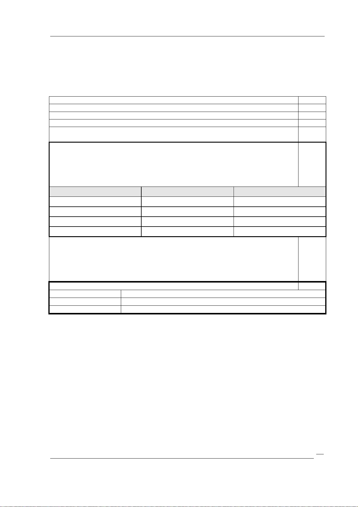
Page
Install detector at the measurement site. 10
Install water cooling if temperatures exceed >50°C. 5
Install evaluation unit.
Connect detector to LB 444 K-40 via two-wire cable. Connect cable to terminal
2a and 2c of evaluation unit.
External product selection
With the external product selection you can measure up to 4 different products.
Both digital inputs have to be used so that 4 different products can be selected.
Digital input 1(DI 1): 18a / 18c
Digital input 2 (DI 2): 20a / 20c
Product DI 1 DI 2
1 0 0
2 0 1
3 1 0
4 1 1
23
Digital input 3 (DI 3): 22a /22c. External Start/Stop signal
Digital input 3 can be used for the following signals:
a) Start/Stop in batch mode
b) Stop continuous measurement. (“freezing” measurement; “HALT” appears on
display)
Digital outputs (relays): These outputs can be used for the following signals:
12a, 12c: Rel. 2: Min. , max. , detector temperature,
14a, 14c: Rel. 3: Min. , max. , detector temperature,
16a, 16c: Rel. 1: Error message
27
Page 34

01/10 347 LB 444 K-40
7.2 Getting Started
7.2.1 Basic Settings
These steps describe how to take the system into operation and how to change the basic
system settings.
Note: To enter numbers, select the entry position with <←←←> and the number you
want with <^^^>. Confirm your selection or new entry with <enter>.
Press <run> to return to the display mode directly any time (except in Service menu).
If no entry is made, the system automatically switches from the current menu item to
the display mode after several minutes.
Important:
After data input the system has to remain turned on for at least 5 minutes to ensure that
all entered data have been saved.
1. Push <more> to select menu General Data / Operating Mode
Push <sk1> to select General Data and <more> to call parameters sequentially.
Enter password and unlock or lock system with <enter>
Check date & time and correct it, if necessary
Check instrument version (e.g. LB444 K-40, version: 3.xx)
Select language
Print Parameter, only if needed
Factory Setting, only if needed (see also Software Functions and System
Configuration)
Push <done> to return to menu group
2. Push <sk2> to select Operating Mode menu and <more> to select parameters.
Select Config Instrument N/A and continue with <more>
Select K20
Define Error mode
etc.
3. Push <more> to select menu Parameter / Product Data.
3.1 Push <sk1> to select Parameter menu and <more> to call parameters sequentially.
Select product: 1
Detector (code “0” or “23” and isotope)
Select “none”
Measuring path in product “1”
Select Measure mode (i.e. continuous)
Enter time constant (e.g.: 300 s)
Disable rapid switchover
“Off”
Disable Interference Radiation
“OFF”.
Define max. count rate (e.g. 100000 cps)
Define min. count rate (e.g. 0 cps)
Product selection
Select “external” or “internal” (only if different products are to be is measured).
Push <done> to return to menu group.
28
Page 35

01/10 347 LB 444 K-40
3.2 Push <sk2> to select Product Data and <more> to call parameters sequentially.
Select product: “1”
Select current output 0 –20 or 4 – 20 mA
Define current output limit values 0/4 and 20 mA:
x% K20 = 4 mA
y% K20 = 20 mA
Define behavior of the current output in case of error message.
Define relay 2: Function (Min), switch point (e.g. 10% )
Hysteresis (e.g. 5%)
Define relay 3: Function (Max), switch point (e.g. 20% )
Hysteresis (e.g. 5%)
Periodic printout:
e.g. 10 min
Push <done> to return to menu group.
7.2.2 Calibration
Prerequisites
Device and detector have been installed.
The device must be turned on at least 1 h prior to the start of calibration.
Container or pipeline have to be filled with the product to be measured.
The calibration is performed as follows:
At different K
memory. The concentration values determined in the laboratory (analysis values) are
entered in a further storage sequence. The correlation of the memories is described
below using one calibration data set as an example.
At least 2 calibration points must be available.
The calibration points should be distributed fairly equally over the entire
measurement range. However, some calibration points may lie outside the measure-
ment range. A calibration only with points outside the measurement range is not
advisable.
Its also possible to use the background radiation as a calibration point. This has to be
measured
d) with empty vessel or
0 concentrations, the counts supplied by the detector are read into the
2
Count rates:
Concentration K20
(lab values):
1: 405 10.2
2 : 583 17.3
3 : 785 25.4
10 : 0 0
29
Page 36

01/10 347 LB 444 K-40
e) with product in the vessel which does not contain any potassium or
f) dismounted detector arranged on a concrete floor or min 20 mm lead or 40 mm
steel plate in front of the radiation window.
A calibration with several very closely adjacent concentration v alues can easily result in
an incorrect calibration curve.
Calibration steps:
Select menu Calibrate / Live Display with <more>.
Push <sk1> to call the Calibrate submenu.
Select product.
Select “no” for suspension measurement more
Select % K20. more
Push <sk1> to call the Data input submenu.
Background for rod detector N/A: continue with more
Deselect Calibr. Data transfer with “no”
1. Read in 1. Rate: cursor appears in the row “1. Rate = cps”.
Push <run>. The count rate is read in. Wait until the measured value has become stable
(approx. 100…300 s). While reading-in the count rate, the concentration of the products
must not change.
While reading in the count rate, take a sample of the product from the pipeline or the
container and determine the concentration of the sample in the lab. If the product is very
inhomogeneous, take several samples in quick succession and calculate an average value
from their concentration values.
2. Stop measurement by pressing the <run> button again.
3. Accept result with <enter>. Cursor jumps to next row.
4. Enter the concentration value of the sample(s) determined in the lab in % K
0 and
2
confirm with <enter>. Cursor jumps to third row.
Push <enter> to skip the current product temperature.
Further calibration points:
Repeat steps 1. – 4. for other different concentrations.
The values must always be available in pairs. If the associated concentration value is
missing, the count rate is automatically assigned the concentration value “0”.
All unused calibration points must contain “0” as count rate. If “0” is already present,
push <more>. Otherwise, delete the values with <clear> and confirm each with
<enter>.
Value pairs where only the count rate but n o concentration is entered, will result in an
incorrect calibration curve.
The entered data can be corrected as needed. The calibration process is carried out in
the menu item Calculate.
Push <sk2> to select Calculate.
Select calibrate mode
30
Page 37
01/10 347 LB 444 K-40
10 15 20 25 30
linear
<enter>.
The calibration is carried out.
The coefficient is calculated by the program.
The calculated zero count rate Io and the coefficient a1 and the square error are
displayed.
If necessary, enter a factor, by which the measured values are multiplied.
If necessary, enter an offset which is added to the measured values.
Push <done> to return to submenu group.
If the current output limits change (see page 26), calculate the calibration curve once
more. (Pos. 16.).
When entering the concentration values, you need not observe a falling or rising order.
However, you must make sure that the correlation of count rate/concentration value is
correct.
7.2.3 Checking the Calibration
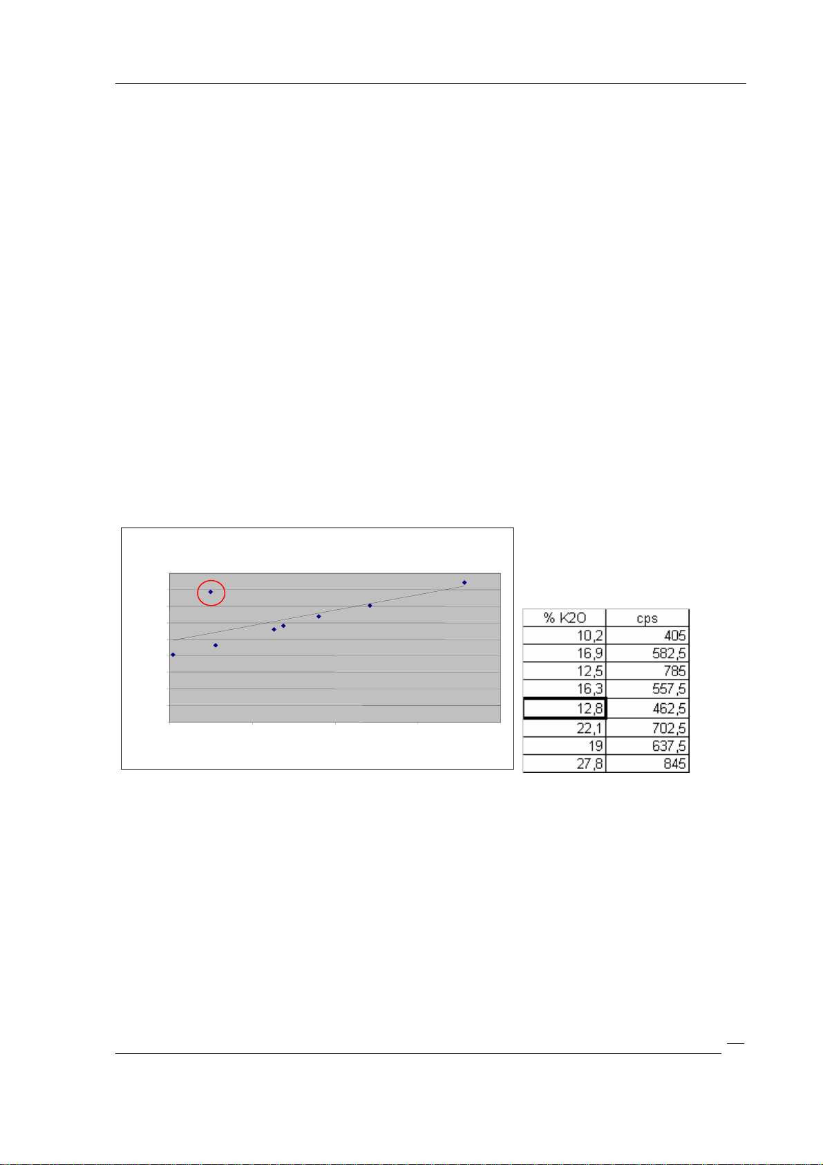
To discover errors during calibration, the calibration curve can be plotted, e.g. with
EXCEL.
Calibration curve
900
800
700
600
cps
500
400
300
200
100
0
% K2O
Figure 12: Calibration curve
Thus, errors in the calibration (marking) can be detected more easily.
Remedy: Correct or clear values and calculate calibration curve once more.
7.3 Live Display
Start measurement: Push <run>.
Stoop measurement: Push <run> again.
Result display % K20:
31
Page 38

01/10 347 LB 444 K-40
Push +….-
to call further value
• current measured value in the selected unit
• averaged count rate (averaging according to entered time constant)
• actual count rate
• display of the adjusted high voltage
7.4 Correcting the Results: Addition and Multiplication
This option should not be regarded as a substitute for careful calibration . It should only
be used for minor corrections. Otherwise we recommend doing a re-calibration.
An additive constant can be entered at Offset, a multiplication factor at Factor Calibrate
menu, submenu Calculate).
7.4.1 Additive Constant
The value stored under Offset is added to the concentration value calculated on the basis
of the count rate. This allows a parallel shift of the calibrati on curve.
Example:
Measuring range 10-30% K20
It is found that the measuring values are too low by 2% K20.
Remedy:
Enter “2.0” at Offset.
All measured values will be increased by 2.0% K20.
Instead of 10% K20, 12% K20 is now indicated and instead of 30% 32% K20. If the
measured values are too high by 2% K20, you have to enter “- 2.0”.
7.4.2 Multiplication Factor
Each measured value is multiplied by the value stored as Factor. This allows you to
change the gradient of the calibration curve.
Example: Measuring range 10 - 30% K20
If you enter 1.1 at Factor, 11% K20 will be display ed instead of 10% K20. At 30% K20
now the value 33% K20 appears. Thus, even the low point of the measuring range is
increased, provided it is not at 0.
Remedy: This can be corrected by entering the appropriate data under Offset and
Factor:
Example:
For 10% K20 the indicated value is correct, instead of 20% K20 th e reading should show
22 K20.
Input value for Factor:
32
Page 39

01/10 347 LB 444 K-40
−
−
−=−=−
2%102%22
LH
minmin
=
F
−
Input value for Offset:
H = upper value of the measuring range in g/cm
H = lower value of the measuring range in g/cm
The same is true if upper and lower point of the measuring range are to be changed by
different values.
Example:
L
actual
L
nominal
H
actual
H
nominal
K = 12 – 11*1.0666 = 0.2674
= FLLK
min
= 11% K20
= 12% K20
= 26% K20
= 28% K20
−
1228
=F
=
−
1126
alnoalno
LH
=
actualactual
actualalno
0666.1
−
OKOK
2%102%20
OKOK
22.1*1010*
3
3
2.1
=
7.5 Automatic Measuring Time Switchover
To quickly update the measured value if sudden concentration changes occur, you can
enable automatic measuring time switchover (Rapid switchover on the menu Parameter,
see chapter 6.36.4).
The smallest value that can be entered is 8 s.
If a sudden concentration change occurs which exceeds the entered threshold (Sigma),
the entered time constant is reduced to 1/10 of the original value, but not less than 0.8
s. Thus, the output signal adjusts much quicker to the new concentration value. The
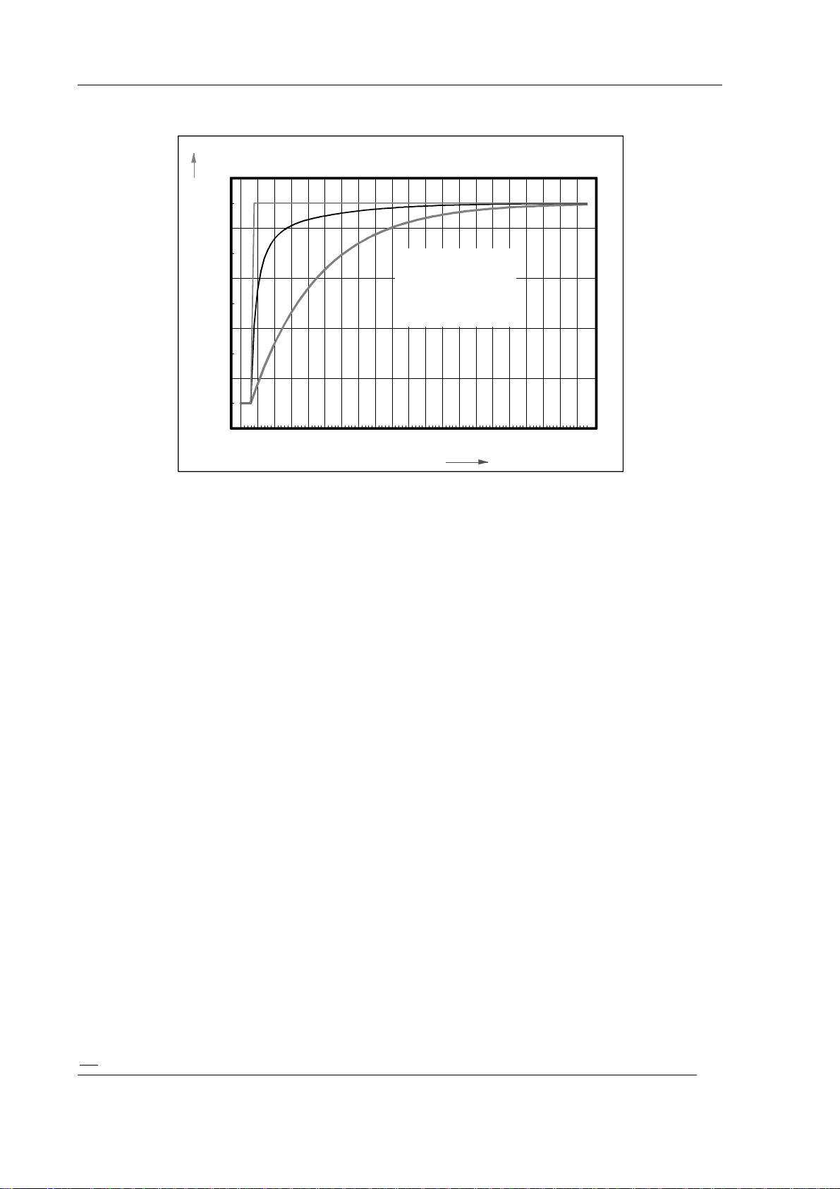
changed time response of the output signal is illustrated in Figure 13.
33
Page 40
01/10 347 LB 444 K-40
Response
100
80
1 Density value
60
40
Display and output signal in %
20
0
-3 2 7 12 17 22 27 32 37 42 47 52 57 62 67 72 77 82 87 92 97
Figure 13: Response
2 Signal trend with
3 Signal trend without
automatic switchover
of time constant
T in s
When rapid switchover is in effect, the measurement first works with the defined basic
time constant. If sudden concentration changes occur which exceed the Sigma band, the
system switches to 1/10 of the time constant and reading and output signal can follow
the concentration change much quicker. At the same time, statistical variations increase
by a factor of about 3. When the concentration value becomes stable again, the system
automatically switches back to the longer basic time constant after a time period that
corresponds to the basic time constant.
7.6 Batch Measurement
If the measurement is carried out on or in a container which is filled and emptied
cyclically, the measurement can be carried out in the batch mode.
With the continuous measurement, the measured value at empty container is 0% K2O.
After the container has been filled, it takes a very long time until the new measured
value is reached again.
In the batch mode the measurement can be started when the container has been filled.
The earlier available measured value is deleted and the measurement is started new.
Thus, the new measured value is available in a much shorter time.
The batch mode is selected via the menu item
“Measure mode” “Batch mode”.
Variable measuring time:
Enter “0” as time constant.
The measurement is started in the batch mode by pushing the <run> button and
stopped by pushing the Sample <run> button again
or
by connecting the terminals 26a and 26c.
Fixed measuring time:
Enter a value > 2 as time constant.
34
Page 41

01/10 347 LB 444 K-40
The measurement is started in the batch mode by pushing the <run> button and stops
automatically when the entered time is over
or
or briefly (>1s) connecting the terminals 26a and 26c.
Once the entered time is over, the measurement is stopped automatically.
In both cases, the current signal remains on the last value until a new measuremen t is
started.
7.7 Radiating Interference Detection
Select the function Radiating interference (menu Parameter, see page 24) to suppress
interfering radiation (e.g. weld seam testing).
Caution:
When this function is on (Radiating Interference <ON>), the automatic switchover of the
time constant (function Rapid switchover) is always off.
When turning this function on, you have to define a Sigma value, which defines a window
for the measuring signal. If the detector signal suddenly exceeds this threshold
• the measurement stops
• the error message “Interference Radiation” appears on the display.
The measured value and the current outputs are held on the last value.
Reset the error message and start the measurement via the keyboard by confirming the
error message with <enter>; then start the measurement with <run> or externally
the digital input.
Note:
Enter n > 5 to rule out false alarms with sufficient statistical safety.
For calculation it holds: Sigma =
Is/
Example:
Count rate I
= 300 cps, n = 6
m
= Im + n * Im
I
S
= 300 + 6 *
I
S
= 404 cps
300
Thus, an alarm is signaled as soon as I/s exceeds the value of 404 cps.
via
Note:
Due to the dynamic behavior of radiating interfering detection, a quick increase of the
pulse rate due to operative factors (e.g. very fast emptying of the vessel or major shortterm concentration changes caused by stirrers) may be interpreted as interfering
radiation.
For example, opening the active beam channel on the shielding can also cause a quick
increase of the pulse rate. You have to reset the alarm that is then triggered, or better,
do not enable radiating interfering detection at first. Enable radiating interfering
detection only after calibration has been performed.
35
Page 42

01/10 347 LB 444 K-40
7.8 Error Messages
7.8.1 Acknowledging Error Messages
All error messages must be reset with <enter>.
Several simultaneously or consecutively occurring errors are stored in an error register in
the order of their appearance; they have to be reset individually by pushing <enter>
several times.
All errors are signaled via the “Error” output (relay 16a/16c).
7.8.2 Error Messages during Operation
Error
no.
32 Wrong
Message Cause, Remarks Remedy
password
Wrong password entered to unlock
the keyboard.
Push “enter” to reset error
message. Enter correct
password.
7.8.3 Error Messages during Calibration
Error
no.
10 Not calibrated Calibration incomplete Perform calibration
36 Missing calib.
37 Curve not clear System could not calculate a
38 Error one-point
39 Measuring path
56 Range overflow Measuring path = 0 Enter measuring path “1”
Message Cause, Remarks Remedy
points
calibration
not defined
Not enough points entered for
selected calibration mode
clearly rising or falling curve.
Absorption coefficient = 0 Absorption coefficient = 0
Measuring path = 0 Enter measuring path “1”
Enter further calibration
points or select another
calibration mode
Check calibration points for
input errors.
Select calibration mode
“linear”.
36
Page 43

01/10 347 LB 444 K-40
7.8.4 Error Messages during Measurement
Error
no.
1 Rate Overflow Count rate > 520000 High voltage wrong.
2 No Detector Rate Detector faulty Replace detector
3 Wrong HV Detector faulty Replace detector
4 Pt 100 wrong
5 4 –20 mA faulty Input current below 4 mA,
6 Detector
7 Trouble with
8 Measurement
9 Detector
10 Not
11 Power fail > 1
12 No input allowed Input locked via password Enter password
47 Rate < Minimum Enter actual count rate < than
48 Rate > Maximum Enter actual count rate > than
61 Replace
Message Cause, Remarks Remedy
Replace detector
temperature
temperature >
65°C
detector
communication
stopped
temperature >
80°C
calibrated
month
photomultiplier
Temperature measurement
activated and no Pt100
connected. Cable faulty.
evaluation unit faulty.
Detector temperature too
high, detector faulty
Cable detector – evaluation
unit interrupted or too long or
cable resistance too high,
detector faulty
evaluation unit faulty.
Measurement process stopped
via digital input
or
measurement stopped
because count rate threshold
has been exceeded or not
reached.
Detector temperature too
high,
Detector faulty
Measurement was started
without calibration
Check date after long period
of power failure
entered min. count rate:
shielding container closed?
detector fault?
entered max. count rate:
detector fault?
pipeline empty and shielding
container not closed?
High voltage increased too
much.
Check cable, replace
detector or Pt 100.
Disable temperature
measurement.
Check input current,
replace, evaluation unit.
Cool detector, if necessary,
replace it
Replace cable or use bigger
wire cross-section.
Replace detector
Replace evaluation unit.
Open digital input.
Disable count rate
thresholds to identify fault.
Replace detector
Perform calibration
When the If this error
message appears already
after a brief period of power
failure: replace Li-battery.
Replace detector
Open shielding container
Replace detector
Close shielding container
Check plateau. Possibly
replace photomultiplier.
37
Page 44

01/10 347 LB 444 K-40
Message Cause, Remarks
Measurement halted
<HALT>
Measurement process stopped via digital input
or
measurement stopped because count rate
threshold has been exceeded or not reached.
Rate Overflow Detector faulty. High voltage outside of the
plateau.
Power Fail Complete failure or drop of power supply below
tolerance level.
No Detector Rate *)
Detector supplies no pulses for at least 60 s.
Wrong HV *)
HV reference voltage of detector too high or
too low.
Measurement is stopped when this error occurs
and has to be restarted by pushing the <run>
button.
Measurement is not stopped. Relay “Failure” is
de-energized.
Error temperature measurement Temperature input faulty (see chapter
“Temperature Compensation” and “Service
Instructions”).
Power failure > 1 month *)
Enter New Date
After a long period of power failure you have to
check and, if necessary, correct the date to
ensure correct decay compensation.
Even if the date is correct, you have to enter
one digit of the year and confirm the input with
<enter>.
*) When these error messages are displayed, the measurement stops automatically and
has to be restarted by pushing the <run> button.
38
Page 45

01/10 347 LB 444 K-40
7.9 System Start/Stop
To stop operation of the measuring system, proceed as follows:
Turn system off.
The water cooling device has to be used if the detector temperature may rise above 50°C
even though the instrument is not in operation.
In case of sub-zero temperatures, empty the water cooling.
To start operation of the measuring system:
Put water cooling in operation again, if it was disabled.
Turn instrument on.
If instrument has been disabled for more than one month, the error message “Power
failure > 1 month” is displayed.
In this case, check and, if necessary, correct the date and time again in the menu sk1:
General Data.
39
Page 46

01/10 347 LB 444 K-40
8 Technical Data
8.1 Evaluation Unit LB 444 K-40
Assembly: 19” module 3 HE, 21 TE; protection type IP 20
Power supply: 115 V ± 10%, 230 V ± 10%, 18-32 V AC/DC
Power consumption: approx. 30 V or 30 W
Temperature range: Operating temperature: 0 - 50 °C; no condensation
Storage temperature: - 40 to + 70 °C
CPU: 32 bit computer, data storage in FLASH- E- PROM.
Weight: approx. 2 kg
Display: LCD display with 4 x 20 characters, illuminated .
Data input via keyboard.
Softkey guided dialog;
Languages: German, English
Data editing possible only after entry
of a freely selectable password .
Time constant: 0.5 – 9999 s with automatic reduction to 1/10 of the
values in case of sudden concentration changes (can be
turned off).
Adjustable response threshold for time constant
switchover.
Automatic decay compensation: for
Inputs/Outputs:
Detector connection Ex II (2) G [EEX ib] II B or Ex II (2) G [EEX ib] II C
Digital inputs: 2 digit a l inputs for external product selection
1 digital input for external start/stop of measurement:
Stop of continuous measurement or
Restart after interruption of measurement due to
Analog output: 0/4 - 20 mA isolated (max. 500 Ω) for measured value
Limit value outputs: 2 relay outputs for measured value max. / min.,
1 relay output for collective failure message
Loading capacity:
AC: Max. 250V, max. 1A, max. 200VA
241
Start/Stop in batch mode,
interfering radiation.
detector temperature, mass pulse, correlation freely
selectable
Am,
137
Cs, 60Co,
244
Cm, 85Kr and 90Sr .
40
Page 47
01/10 347 LB 444 K-40
DC: Max. 300V, max. 1A, max. 60 W non-reactive load
Current input: 0/4 - 20 mA isolated
for input of temperature signal or
volume current signals
Interfaces: RS 232. Port for data transfer from evaluation unit to printer
or PC
8.2 Detectors
Type
LB 5401-03 50/50 18 0 No
LB 5430 150/150 52 23 No
Protection type: IP 65,
Housing: Stainless steel housing
Cable entry: M16 external cable diameters 7...10 mm for connection cable
Temperature range:
Operating
temperature:
Storage
temperature:
Crystal ∅
/ l in mm
detector - evaluation unit and M 12 for external cable diameter
7...10 for connection of Pt 100
- 20 to + 50°C. A water cooling device is availab le for higher
temperatures. Monitoring of detector temperature and alarm if
max. permissible temperature is exceeded.
- -40 to + 70 °C
Weight
kg
Detector code Ex protection
Connection cable evaluation unit - detector
Cross-section in mm² Max. cable length in m
1 1000
1.5 1500
2.5 2500
41
Page 48

01/10 347 LB 444 K-40
9 Service Instructions
9.1 General Safety Precautions
Any time you are working on electrical components, you have to observe the relevant
safety regulations. Please refer to the Safety Summary at the beginning of this operating
manual.
9.2 Evaluation Unit LB 444 K-40
The evaluation unit is provided with an error control which also monitors the detector
functions. An error code appears on the display if an error is detected. For information
about the error and possible causes please refer to the error code list. In case of
hardware errors the evaluation unit has to be replaced.
If no error code is displayed, the electronics is working properly and all measured values
and parameters lie in the normal possible range. Possible function problems must then
have another cause.
“Total Reset” should be performed only in exceptional cases and after consultation with
Berthold.
To perform a “Total Reset”, turn the instrument off; then push the Clear button while
you turn the instrument on.
All entered date will be deleted and the default values restored.
Error code list
No. Problem Cause
1 Rate Overflow Count rate > 520000cps
2 No Detector Rate Error in detector or during transmission
3 Wrong HV HV < 500V or > 1500V, outside control range
6 Detector temperature >
65°C
7 Trouble with detector
communication
8 Measurement stopped Measurement stopped by closed contact 22 a/c
9 Detector temperature >
80°C
10 Missing calibration Calibration has to be terminated with <enter> and
11 Power fail > 1 month Instrument has been turned off for more than one
12 No input allowed Device locked by password or wrong password entered
33 Wrong password Wrong password entered
36 Missing calib. points Not enough calibration points available
37 Curve not clear Calibration not steady
39 Measuring path not defined Measuring path not yet entered
46 Radiating interference New start with <run> or via input 3 (22a/22c)
Detector temperature has exceeded > 65°C
Data transfer between detector and evaluation unit
faulty
Detector temperature has exceeded > 80°C
<more>
month. Enter new date
42
Page 49

01/10 347 LB 444 K-40
50 I.Max/I.Min value Current output entered incorrectly
51 Current input error Current input range entered incorrectly
52 Current output limit value Current output range entered incorrectly
53 Current input error Current input too high > 20mA
54 Device not calibrated Calibration has to be terminated with <enter>
56 Range overflow Input value outside permissible range
57 Wrong input value Input value outside permissible range
58 Calibration faulty Wrong calibration
60 Digital inputs for product
selection allowed
Window for product selection in menu Parameter set to
external.
Problem Possible Cause Potential Solution
No display No power supply Check mains cables
Check fuses
Display unreadable Processor error Note error code
Perform total reset
Replace evaluation unit
No pulse rate
(Error code 2)
Power supply for
detector interrupted
Check cable to detector
Detector is faulty Replace detector
Result reading
shows drifts
Detector stabilization
faulty
Replace detector
Photomultiplier faulty Replace photomultiplier
Decay compensation
activated
43
Page 50

01/10 347 LB 444 K-40
10 Service
10.1 Service Menu Overview
44
Page 51
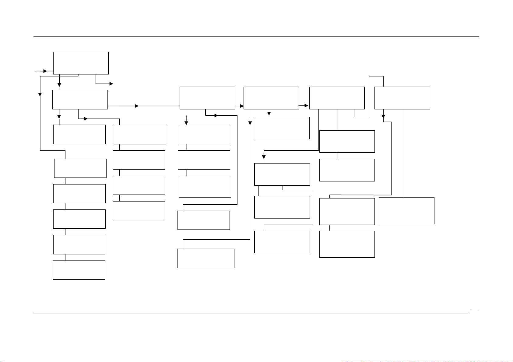
01/10 347 LB 444 K-40
sk1: Service Menu
sk2: Mass Flow
sk1 sk2 more
sk1: Test calculate
sk2: I / O - Test
sk1 sk2 more
Testrate 12345 cps
Output Curr : 10.0 mA
1.2345 g/cm3
Unit Mass Flow
[kg/h, t/h]
t/h
Range input
{at 20 mA]
Value: 100 m3/h
Flow
Value 87.00 m3/h
Ext. Mass Counter
Tons per cycle
OFF/0,01/0,1/1/10
Erase mass integrator
no/ yes
Set output cur
Current : 9.0mA
View input cur.
Current: 12.0mA
Relay 1: ON
Relay 2: OFF
Relay 1: ON
Input 1: OFF
Input 2: OFF
Input 3: ON
sk1: HV Adjustment
sk2: Status request
sk1 sk2 more
High Voltage
Value : 800 V
Save Default
Value: 850 V
Read Default
Value: 850 V
Temperature = 45.2°C
Det. Temp. = 28 °C
Counts = 3210/s
For Detector - Reset
please press (sk 1 & clear)
sk1
sk1: Reset Detector
sk2: Pt 100 adjust
sk1 sk2 more
For Pt 100-Adjust
please press
(sk2 & clear)
sk1: Measure Plateau
sk2: Request Plateau
sk1 sk2 more
Plateau measurement
running ......
IIIIIIIII...........................
HV( 500): 817/s
HV( 560): 884 /s
HV( 620): 923/s
+ - done
sk1: Plateau
sk 2: Adj. Current out
sk 1 sk2 more
Current 1.8 mA
Offset: 4123
-
Current 18 mA
Offset: 345
-
Curr. Input Adjust
Set value 1.8 mA
Real value 1,7 mA
+ - more
Curr. Input Adjust
Set value 18 mA
Real value 17.5 mA
+ - more
sk1: Adj. Cur. input
sk 2: Relay Delay time
sk 1 sk2 more
Relay delay
Value: 50 ms
45
Page 52

01/10 347 LB 444 K-40
10.2 Service Menu
The Service menu functions support input of test values (output current, count rates) to
simulate instrument functions
• check of outputs and inputs
adjustment of analog outputs and inputs
adjustment of Pt 100 input (N/A)
• plateau recoding of detector
• manual setting of high voltage for test purposes.
The individual functions are described below.
Test calculate:
Any pulse rate within the calibration range can be entered. The count rate supplied by
the detector will then be ignored.
The respective output current is calculated from the count rate and the concentration
value.
Output current and the respective concentration value are displayed as a result of the
defaulted pulse rate.
The product temperature supplied via Pt 100 or as current signal is taken into
account when calculating the measured value. Therefore, the temperature
compensation for the test has to be disabled. To do this, select “Density without
TC”.
After completion of the test, reset the test count rate to “0”!
I/O Test Output Current:
To use this function, the measurement must not be in the RUN mode.
To test the connected instruments, you can set any output current between 0 – 22 mA.
View input current:
Shows the current measured at the current input.
Relay 1/2/3:
The relays can be switched to test the signal circuits (ON = relay energized)
Input 1/2/3:
Shows if the inputs are open or closed. (OFF = input open)
HV Adjustment:
Set HV detector
With the standard setting “0” the detector works with automatic high voltage control. If
you enter a high voltage value for special tests, the high voltage control is disabled. Th e
entered value is used as fixed high voltage. In this case, the info HV-Test is displayed in
the measurement menu or the live display (instead of HV auto).
Set this value to “0” again when you exit the Service menu. Otherwise, the
measurement device will not work correctly.
Status request
This menu item includes the
detector temperature
current counts
high voltage.
46
Page 53

01/10 347 LB 444 K-40
Reset Detector:
To reset the detector you have to push the buttons <sk1> and <clear> at the same
time. This will interrupt the plateau recording and reset the detector electronics. A reset
also has to be performed when the microprocessor of the detector has been replaced.
Pt 100 Adjust (N/A)
The Pt 100 input is adjusted by the manufacturer. New adjustment is necessary only
when detector boards or the microprocessor of the detector have been replaced.
Apply resistance with 100 Ω (with lowest tolerance) at Pt 100 input of the detector
(terminals 3 and 4,).
Select menu item “Pt 100 Adjust”
Push <sk2> and <clear> at the same time. The message “Pt 100 adjustment
running...” is displayed. The adjustment is finished after approx. 5 s.
Then connect resistance thermometer to detector, terminals 3 and 4.
Pt 100 adjustment should be performed by trained personnel only!
10.2.1 Plateau Check
Measure Plateau
A detector plateau can be recorded automatically in steps of 60 V, e.g. to check the
proper function of the NaI crystal multiplier combination.
Working principle of scintillation counters
The detector (scintillation counter) is comprised of:
a) an organic scintillator (PVT)
or
b) a sodium iodide crystal doped with Thallium
c) photomultiplier
d) electronics unit
As the gamma radiation hits the detector, it triggers minute flashes of light in the crystal
which are invisible to the naked eye. These flashes of light release electrons from the
light-sensitive cathode (photo cathode) of the photomultiplier. This electron current is
amplified via a dynode system resulting in an electrical impulse at the photomultiplier
output for each light flash.
The high voltage required for operation of the photomultiplier is generated in the
electronic unit.
The scintillation counter is equipped with a drift compen sation w hich compensates f or the
effects of aging and temperature-related gain variations, thus ensuring high long-term
stability.
Malfunctions of the scintillation counter are not alw ays indicated by a missing pulse rate.
It is also possible that the specific Gamma sensitivity appears to have changed or
obvious instabilities are apparent. This error can be detected only by means of a plateau
check. The evaluation unit LB 444 K-40 includes a function for automatic plateau
recording.
Please keep in mind:
The scintillation counter may remain at the measuring point if it is certain that the
concentration in the measuring path will remain absolutely constant during the time
of the check (approx. 10 min.). Otherwise, the check has to be carried out in the
workshop. An appropriate amount of potassium salt (10 kg) has to be provided directly in
front of the detector.
Select Plateau / Measure Plateau in the Service menu.
Upon completion of the plateau measurement, you may invoke the function Request
Plateau to display the value pairs HV-steps/count rate.
The detector works properly if a clear plateau is visible; the position of the plateau is
47
Page 54
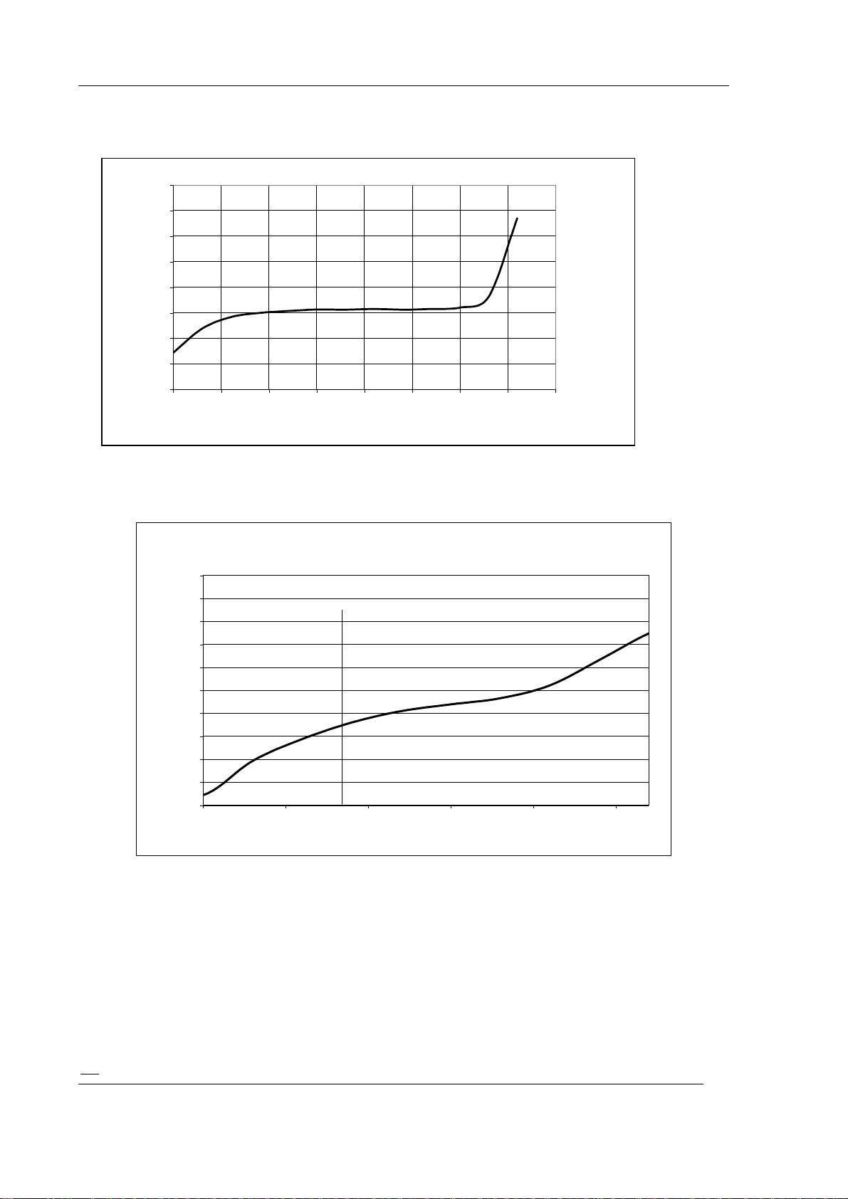
01/10 347 LB 444 K-40
irrelevant.
16000
14000
12000
10000
8000
cps
6000
4000
2000
0
500 600 700 800 900 1000 1100 1200 1300
HV in V
Figure 14: Plateau curve with Na I crystal (LB 5402)
Plateau LB 5430
50000
45000
40000
35000
30000
25000
cps
20000
15000
10000
5000
0
560 660 760 860 960 1060
Setpoint of the HV control
HV in V
Figure 15: Plateau curve with organic scintillator (LB 5430)
Plot the count rate vs. the high voltage, as shown in the diagram above.
If the count rate in the flattest part of the curve changes
a) by more than 5% per 100 V high voltage for the LB 5402,
b) by more than 15% per 100 V high voltage for the LB 5430,
the scintillation counter will operate unstable. The detectors or at least the crystal
48
Page 55

01/10 347 LB 444 K-40
multiplier combination have to be replaced.
Request Plateau
The value pairs of the plateau measurement may be displayed here and may be plotted
to assess the curve.
Adjust current output
Current 1.8 or 18 mA:
Adjustment of output current to the values 1.8 mA and 18 mA by incrementing or
decrementing the numerical value on the display.
Adjust current input
Target value/Actual value
Adjustment of input current. Feed current of 1.8 mA.
Confirm display with <enter>.
RUN appears on the display, the adjustment is running. Push <more> to stop the
adjustment and continue with the next item.
Then feed 18 mA current and confirm with <enter> and push <more> to continue.
49
Page 56
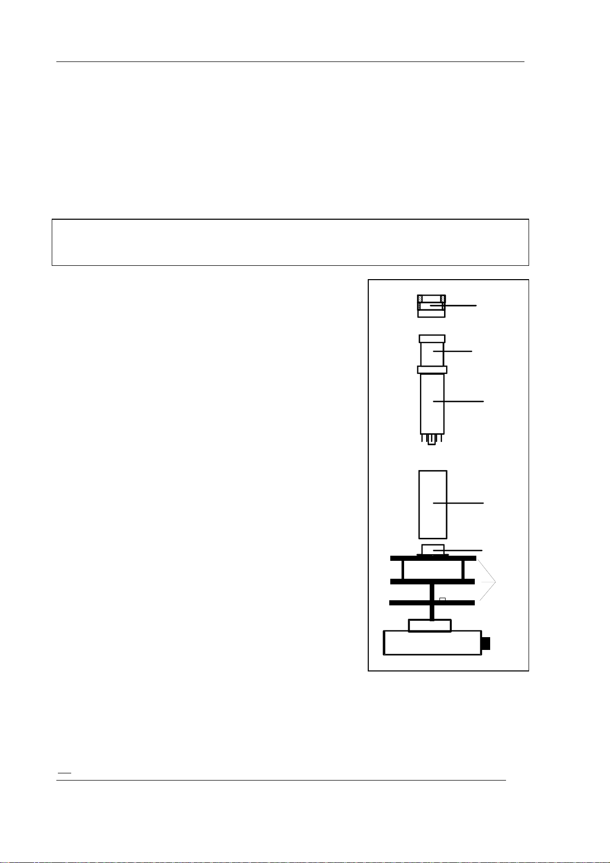
01/10 347 LB 444 K-40
10.3 Detector
10.3.1 Checking the Crystal-Multiplier Assembly
A plateau that is too small or too steep indicates faults in the crystal-multiplier assembly.
Please proceed as follows to perform a visual inspection of crystal and multiplier:
Switch off the scintillation counter before opening the instrument.
Do not perform the check in bright daylight, as this may damage the photo
cathode of the photo multiplier.
Open the scintillation counter by removing the cover of
the connection box first and then the screws of the base.
The entire electronics (1) with the crystal/multiplier
combination can then be detached from the housing.
Remove photo multiplier combination from base (2) and
unscrew ring nut (3) on front panel. The multiplier (4)
including crystal (5) can now be detached from the Mumetal shielding (6).
A thin layer of silicone oil between crystal and mu ltiplier
ensures optical coupling; silicone oil is rather viscous,
particularly at low temperatures. Carefully detach the
crystal from the multiplier window by gently sliding the
crystal sideways.
Do not wipe off the silicone oil layer if no new silicon oil is
available!
Check:
The crystal must be perfectly clear inside and not show
any dull areas. Its typical color is white. A yellowish to
brownish coloring is a sign of thermal overload and
indicates that the crystal has to be replaced. The
surrounding white reflecting la yer must not be damaged.
You can only check the photo multiplier for glass
breakage or other mechanical damage. Other faults
cannot be identified by visual checks alone. However, if
the crystal does not show any faults, a bad plateau
indicates that the photo multiplier is faulty.
1 = electronics part with
(a) CPU,(b) HV, (c) voltage divider
2 = base
3 = ring nut
4 = photomultiplier
5 = crystal
6 = Mu-metal shielding
(c)
(b)
(a)
Figure 16: Assembly of the
scintillation counter
3
5
4
6
2
1
50
Page 57
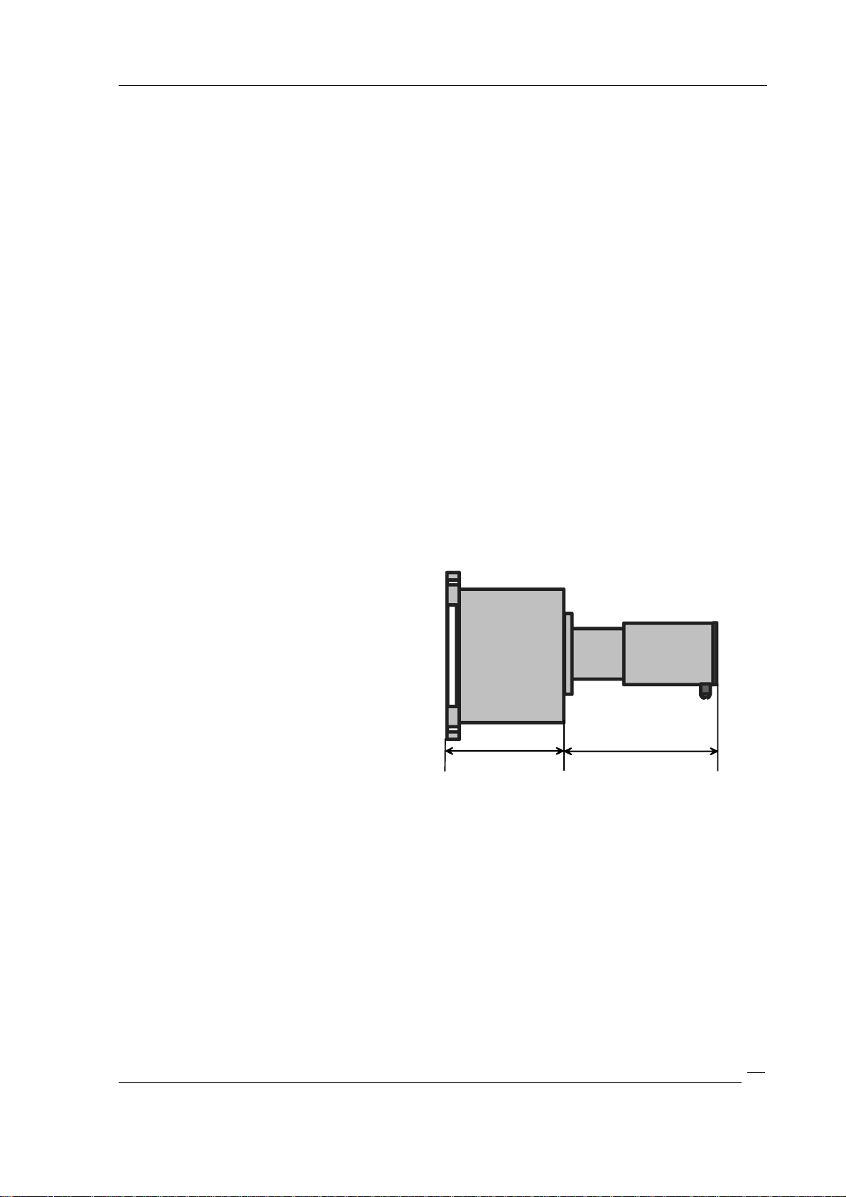
01/10 347 LB 444 K-40
The multiplier window is coated with a vapor-deposited layer acting as photocathode.
This layer gives the window a brownish tint similar to smoked glass. If this layer is no
longer present or if it is stained, then the photocathode has been destroyed (e.g. by
overheating, glass breakage, or incident light), and the multiplier must be replaced.
Faults caused by damage to the dynode systems (e.g. by excessive vibration) cannot be
identified by appearance. If in doubt, replace the multiplier .
The glass pane at the mating face to the photo multiplier must not show any cracks.
Before re-assembly, apply a drop of clean silicon oil between crystal and multiplier and
distribute it evenly by gentle rubbing to ensure sound optical connection between both
components. Attach the Mu-metal screen and fix it with screws, making sure that the
Mu-metal screen is only under light tension.
Re-assembly:
Set the crystal again onto the front face of the photo multiplier and twist both compo-
nents several times counter-clockwise. If you have to replace a component, apply 1 or 2
drops of silicone oil on the mating faces of the new and old component. It may also
suffice to press the new component against the mating face of the old one and to turn it
several times. Reassemble parts properly.
Just as after replacement of a complete detector, the calibration should be checked
immediately.
10.3.2 Testing and replacement of the photomultipliers in the
detector LB 5430
Figure
17:
As-
1
sembly of the scintillation
counter
The organic scintillator is in the front housing part of the detector LB 5430 (1 in Fig. 17 ).
This housing should only be opened by the service staff from Berthold.
The detector electronics and the photomultiplier are located in the rear housing part (2 in
Fig. 17 )..
The same rules and criteria apply as for the detector LB 5430 regarding dismantling and
inspection.
The detector must stand upright on the flange for dismantling and installation of the
detector electronics. An installation of the electronics in horizontal position of the
detector is very difficult. The multiplier can get damaged.
1. Dismantle electronics with photomultiplier (see above)
2. Check photomultiplier and replace if necessary.
3. Put 1-2 drops of silicone oil on the frontal area of the ph otomultipliers before assembly
2
51
Page 58

01/10 347 LB 444 K-40
and rub it in gently with your finger.
4. Guide the electronics and the photomultiplier back into the housing until the
photomultiplier stands up on the ground of the detector housing. Turn the electronics
without exerting pressure several times at about 90 ° back and forth. This distributes the
oil on the frontal area of the photomultipliers evenly.
5. Screw the electronics on at the base.
6. Screw on lid.
10.4 Replacing the Evaluation Unit LB 444 K-40
To replace the entire LB 444 K-40 evaluation unit, please proceed as follows:
Connect new evaluation computer.
In submenu Calculate (menu Calibrate), select the calibration mode (K2O) .
Enter data using the set-up protocol and date of the original set-up.
Start calibration process: select calibration more with <enter> and then push <more>.
Start measurement again with <run>.
Example:
Calibration
point
1 405 10,2 01.02.96
2 583 16,9 01.02.96
3 785 22,5 01.04.96
4 558 22,1 01.04.96
5 703 19 01.10.96
Count rates % K2O Date
52
Page 59

01/10 347 LB 444 K-40
10.5 Setup Protocol
Measuring Point ............................................ Date: ...........................
Product: ........................................................
Parameter Range Value
Password
Instrument ID
Program version
Configure instrument
Radiation measure yes / no
Error mode Hold/continue
Product no. 1/2/3/4
Measuring path cm
Measure mode
Time constant s
Rapid switchover ON/OFF
Sigma for radiating
interference
Count rate limit (min) cps
Count rate limit (max.) cps
Current out for concentration 0-20mA or 4-20mA
0/4 mA
20 mA
Current output error Hold Value: 0-22mA
0-10
-1
-1
53
Page 60

01/10 347 LB 444 K-40
Parameter Range Value
Relay 2 setup Min or Max:
Hysteresis : 0-10%
Relay 3 setup Min or Max:
Hysteresis : 0-10%
Data input:
Count rate cps
Concentration (lab values) Date Temperature °C
1
2
3
4
5
6
7
8
9
10
Calculation:
Parameter Range Value
Calibrate mode on/lin/squ/cub/auto
Result a1
Background count rate Io
Coefficient a1
Coefficient a2
Coefficient a3
Square error
Factor 1 to 10
Offset
54
Page 61
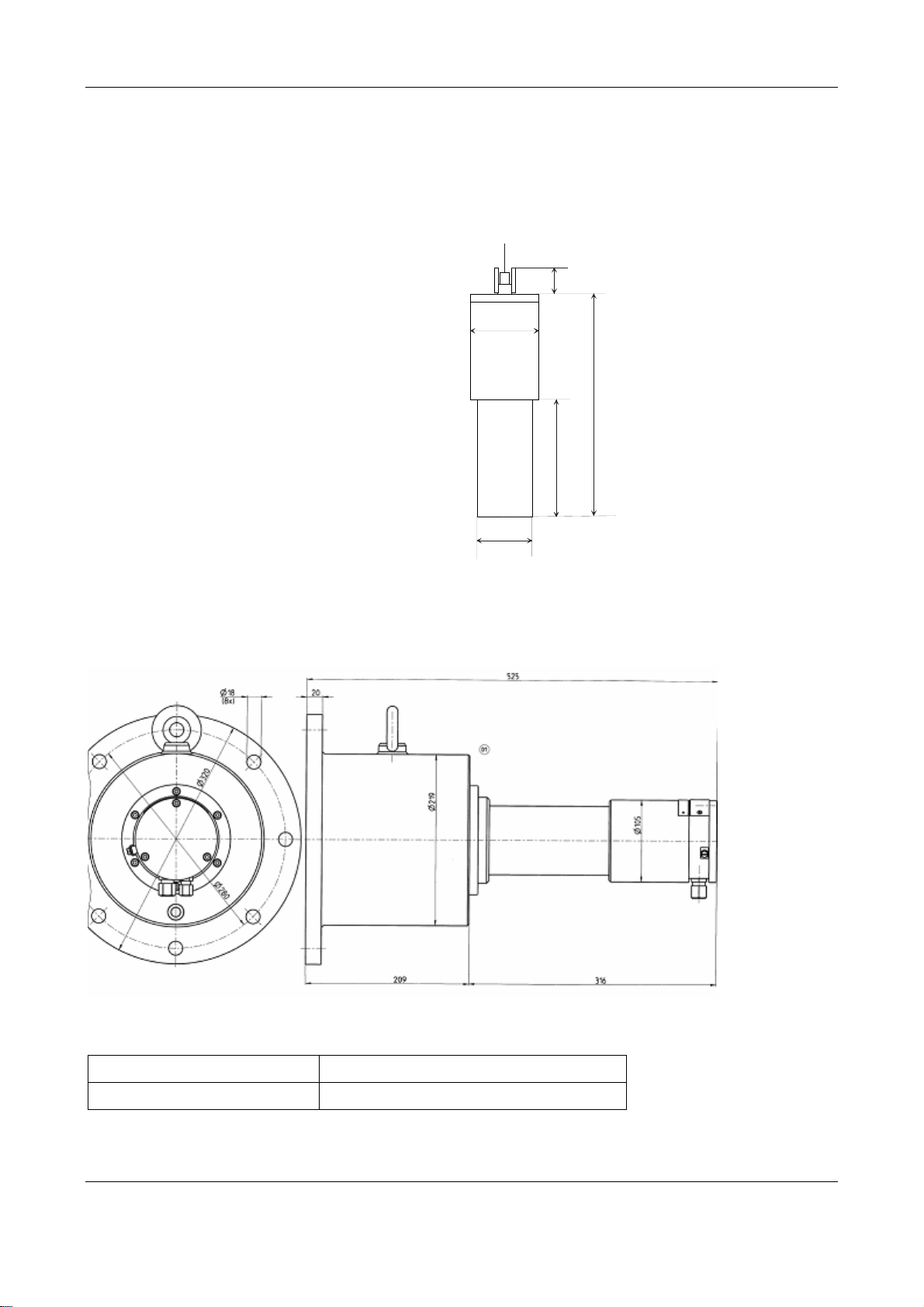
01/10 347 LB 444 K-40
11 Dimensional Drawings
11.1 LB 5402
Weight approx. 6 kgs
Cable gland M16
for cable dia. 7-10 mm
approx. 40
dia.
105
346
208
dia.
75.5
11.2 LB 5430
LB 5430
Weight appr. 52 kg
55
Page 62
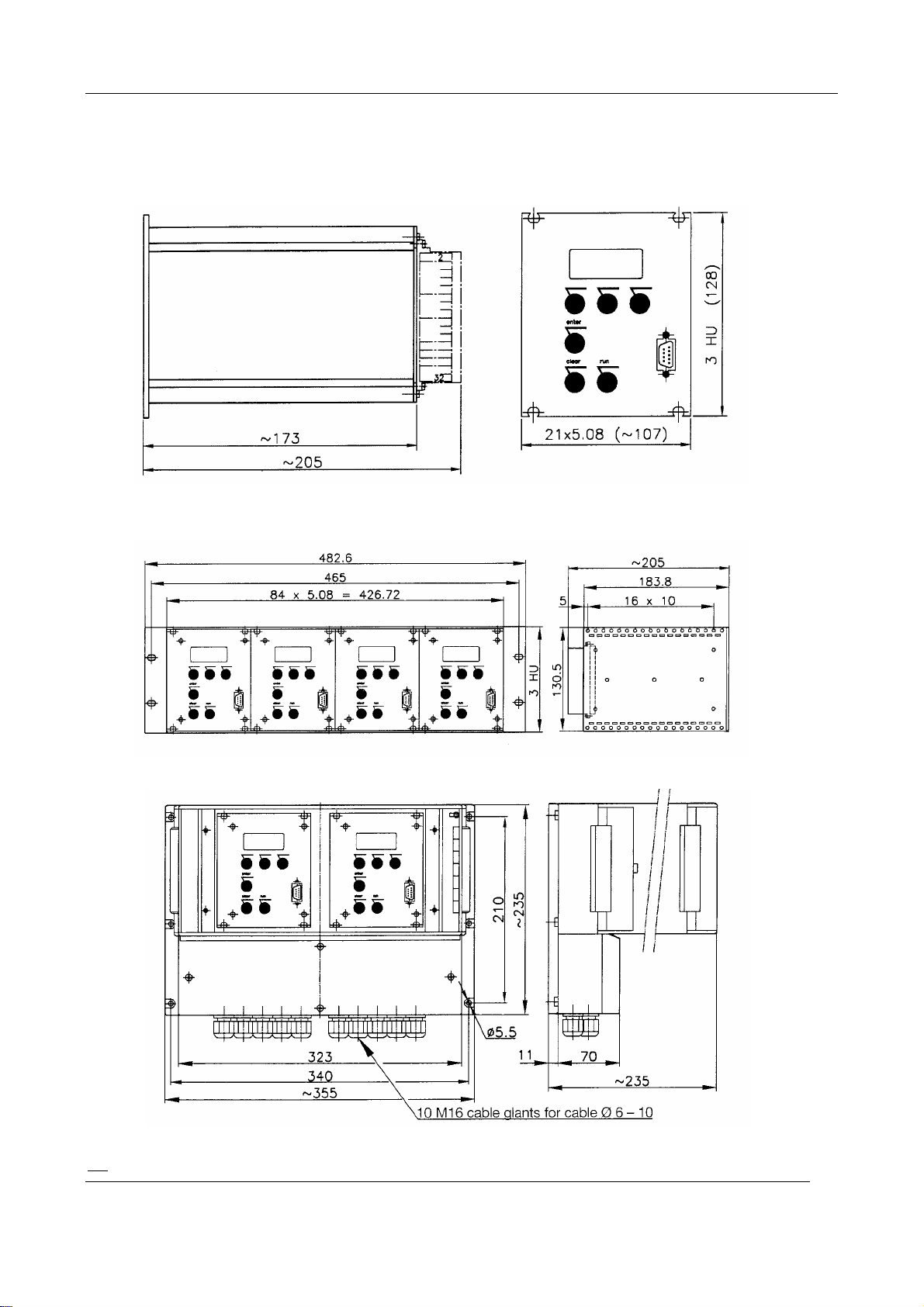
01/10 347 LB 444 K-40
11.3 LB 444 K-40
19” module
Installation in 19” rack
Installation in wall housing
56
Page 63
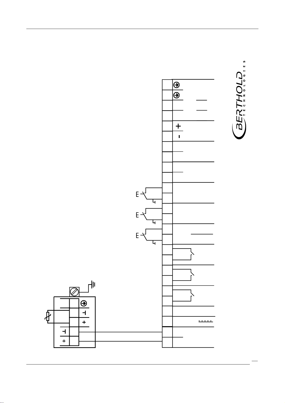
01/10 347 LB 444 K-40
2a2a2a2a2a2a2a2a2a2a2a2a2a2a2a2a2a2a2a2a2a2a2a
32c2a2a2a2a2a2a2a2a2a2a2a2a2a2a2a2a2a2a2a2a2a2a2a18a
2a2a2a2a2a2a2a2a2a2a2a2a2a2a2a2a2a2a2a2a2a2a2a
30c 2a2a2a2a2a2a2a2a2a2a2a2a2a2a2a2a2a2a2a2a2a2a2a32a
2a2a2a2a2a2a2a2a2a2a2a2a2a2a2a2a2a2a2a2a2a2a2a
28c 2a2a2a2a2a2a2a2a2a2a2a2a2a2a2a2a2a2a2a2a2a2a2a30a
2a2a2a2a2a2a2a2a2a2a2a2a2a2a2a2a2a2a2a2a2a2a2a
26c 2a2a2a2a2a2a2a2a2a2a2a2a2a2a2a2a2a2a2a2a2a2a2a28a
250/125 V ~
230/115 V ~
~~
0/4-20mA
potential
+ -
0/4-20mA
potential
+ -
freier
Eingang
freier
Ausgang
Isolated
Isolated
Netz / Line
24 V -
input
output
2a2a2a2a2a2a2a2a2a2a2a2a2a2a2a2a2a2a2a2a2a2a2a
RS
RS
Start /Stop
Ext.
Ext.
Batch
Produkt
Produkt
2
1
RS 485
Stop
Messung
Measur
ement
Product
2
0 V (+ 24 V)
Product
1
Fehler
Min.
12 3
Failure
Max.
Det./
Temp.
Digitale Eingänge
Digital Inputs
24c 2a2a2a2a2a2a2a2a2a2a2a2a2a2a2a2a2a2a2a2a2a2a2a26a
2a2a2a2a2a2a2a2a2a2a2a2a2a2a2a2a2a2a2a2a2a2a2a
22c 2a2a2a2a2a2a2a2a2a2a2a2a2a2a2a2a2a2a2a2a2a2a2a24a
2a2a2a2a2a2a2a2a2a2a2a2a2a2a2a2a2a2a2a2a2a2a2a
20c 2a2a2a2a2a2a2a2a2a2a2a2a2a2a2a2a2a2a2a2a2a2a2a22a
2a2a2a2a2a2a2a2a2a2a2a2a2a2a2a2a2a2a2a2a2a2a2a
18c
2a2a2a2a2a2a2a2a2a2a2a2a2a2a2a2a2a2a2a2a2a2a2a
16c 2a2a2a2a2a2a2a2a2a2a2a2a2a2a2a2a2a2a2a2a2a2a2a20a
2a2a2a2a2a2a2a2a2a2a2a2a2a2a2a2a2a2a2a2a2a2a2a
14c 2a2a2a2a2a2a2a2a2a2a2a2a2a2a2a2a2a2a2a2a2a2a2a16a
PA
2a2a2a2a2a2a2a2a2a2a2a2a2a2a2a2a2a2a2a2a2a2a2a
12c 2a2a2a2a2a2a2a2a2a2a2a2a2a2a2a2a2a2a2a2a2a2a2a14a
Rel.2 Rel.3 Rel.1
Min.
Max.
Det./
Temp.
Impuls
521
count
Pt 100
34
LB 44../LB 54..
Probe
Detektor
Für eigensichere Installationen
[EEx ib] Kabeladern mit 10 mm
Schrumpfschlauch überziehen
10 mm long heat shrink sleeving
must be used to comply with
the [EEx ib] safety certification.
NYMHY 2*1mm²
Kabel/Cable:
+ 24 V
2a2a2a2a2a2a2a2a2a2a2a2a2a2a2a2a2a2a2a2a2a2a2a10a 2a2a2a2a2a2a2a2a2a2a2a2a2a2a2a2a2a2a2a2a2a2a2a10c
2a2a2a2a2a2a2a2a2a2a2a2a2a2a2a2a2a2a2a2a2a2a2a2a 2a2a2a2a2a2a2a2a2a2a2a2a2a2a2a2a2a2a2a2a2a2a2a2c 2a2a2a2a2a2a2a2a2a2a2a2a2a2a2a2a2a2a2a2a2a2a2a12a
+ -
Detektor
Probe
Anschlussplan / Connection diagramm LB 444 19 " Rack
57
Page 64
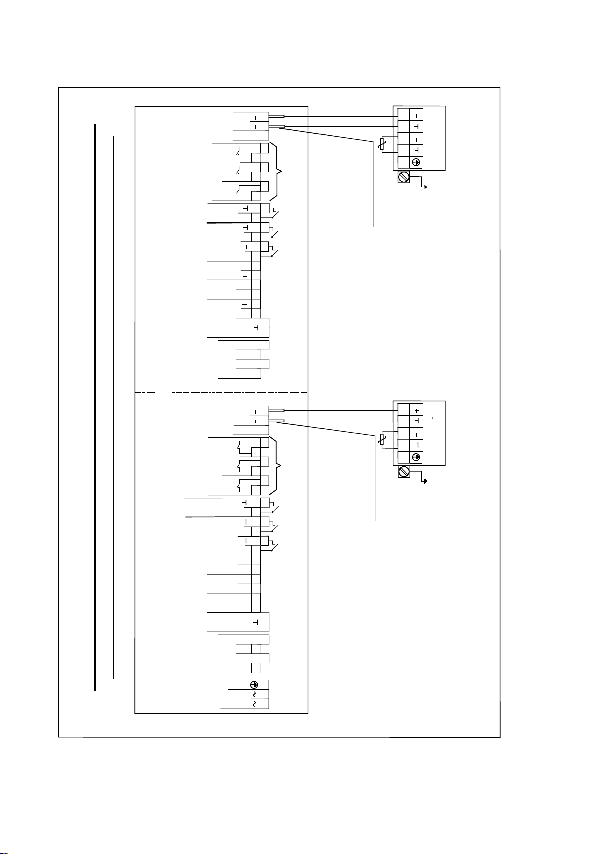
01/10 347 LB 444 K-40
NYMHY 2*1mm²,max. 1000 m
Detektor / Probe
65
64
63
Det. Temp.
Min. / Max.
Kanal B
Channel B
Fehler / Failure
Start / Stop
Batch /Reset
Product
Ext.
potentialfrei /isolated
Stromausgang / Current output
RS 485
0/4 - 20 mA
Stromeingang / C urrent input
Masse / Ground
Aux. Voltage
Hilfsspg. Ausg.
62
48
Rel.2 Rel.3
47
Rel.1
46
45
44
+ IN IN
43
42
RS 1
RS 2
39 40 41
37 38
GND
+ 24 V
36
GND
+ 24 V
35
60 61
59
58
57
51- 56
50
49
Relais
3
Für eigensichere Installationen
[EEx ib] Kabeladern mit 10 mm
Schrumpfschlauch überziehen
2
Digital inputs
1
Digitale Eingän ge
10 mm long heat shrink sleeving
Kabel/Cable:
Probe
Detektor
LB 44../LB 54..
54321
PA
must be used to comply with
the [EEx ib] safety certification.
Anschlussplan Wandgehäuse LB 4460 für Dichtemessung LB 444
Wiring Diagram Cabinet LB 4460 f or Density Measuring LB 444
NYMHY 2*1mm²,max. 1000 m
Kabel/Cable:
Detektor / Probe
34
32 33
Pt 100 Pt 100
54321
must be used to comply with
the [EEx ib] safety certification.
+ -
Rel.3
Rel.1 Rel.2
IN IN IN
+
RS 1
RS 2
GND
+ 24 V
GND
+ 24 V
PE
31
16 17
29 30
15
28
13 14
26 27
12
11
10
9
678
20-25
1918
5
4
1 2 3
Relais
123
Digitale Eingänge
Für eigensichere Installationen
[EEx ib] Kabeladern mit 10 mm
Schrumpfschlauch überziehen
10 mm long heat shrink sleeving
Digital inputs
Det. Temp.
Min. / Max.
Fehler / Failure
LB 4460 Wandgehäuse / wall mounted cabinet
Start / Stop
Batch /Reset
Product
Ext.
potentialfrei /isolated
Stromausgang / Current output
RS 485
0/4 - 20 mA
Stromeingan g / C urrent input
Masse / Ground
Aux. Voltage
Hilfsspg. Ausg.
24 V AC/DC
230/ 115 V AC
Kanal A
Channel A
Netz / Power
Probe
Detektor
LB 44../LB 54..
PA
58
 Loading...