

Page 1
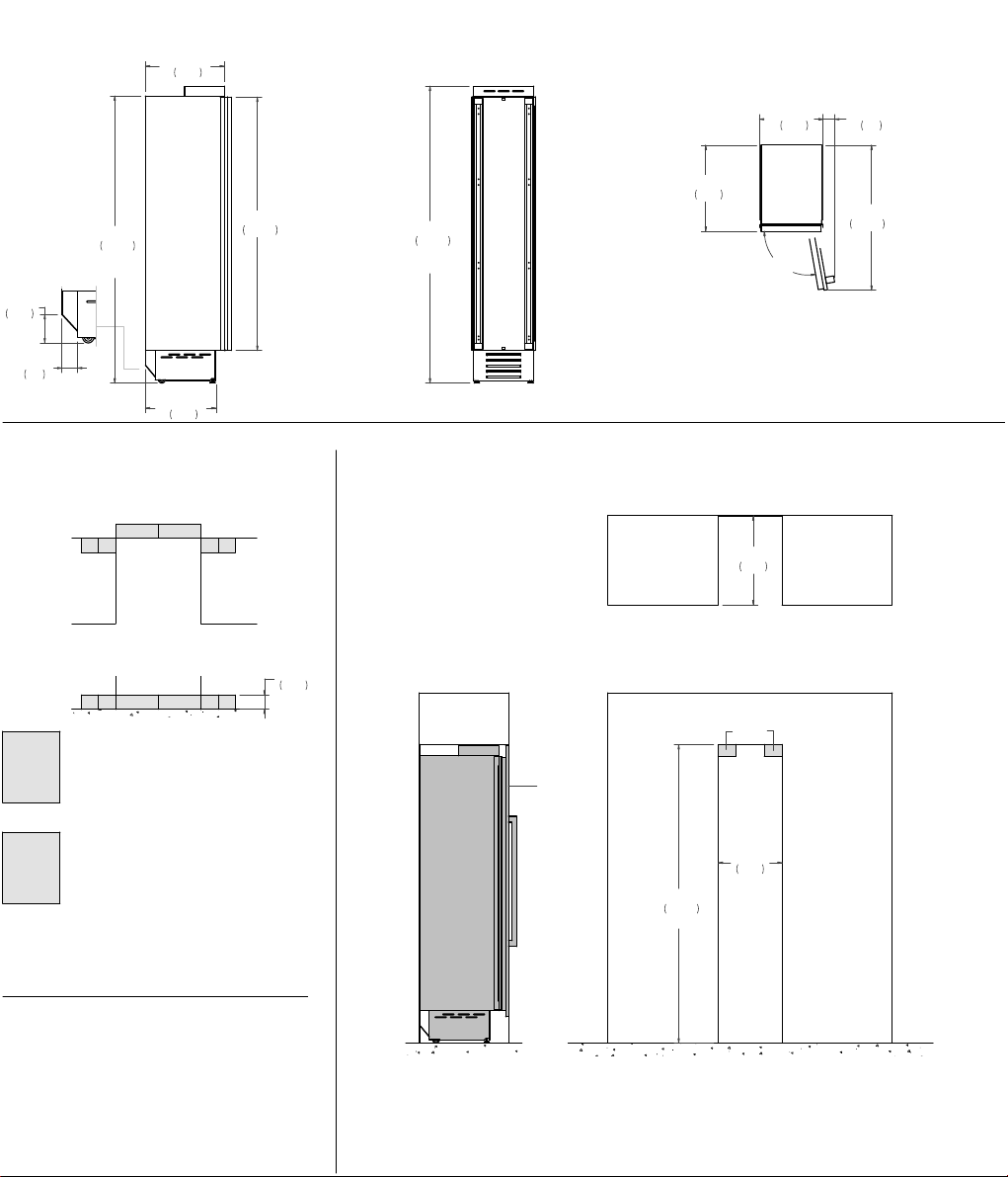
PRODUCT DIMENSIONS
A
SIDE VIEW
5"
127
2 3/4"
70
80 3/4"
2050
1"(25)
22 1/4"
565
+
19 7/8"
505
ELECTRICAL & WATER
CONNECTION
TOP VIEW
WE
EWEW
71 1/8"
1808
FRONT VIEW TOP VIEW
24 1/4"
615
83 1/2"
2120
+
1"(25)
* Maximum Overall Handle Dimension
** Width of 3/4” (19mm) Door Panel
CUTOUT DIMENSIONS
TOP VIEW
25"
635
17 15/16"
456
100°
3 1/4"
82
40 3/4"
1036
*
**
FRONT VIEW
EWEW WE
properly-grounded,
horizontally-mounted electrical
E
receptacle should be installed
according to this drawing.
To connect to the water supply
system, a 3/4” NPT waterline
W
with accessible shut-off valve
must be supplied.
Connection(s) placement within the
opening may require additional
cabinet depth.
INSTALLATION
REQUIREMENTS
If the appliance(s) is not connected
through the side profile trims to
secured cabinetry anti-tip brackets
must be installed.
5"
127
SIDE VIEW FRONT VIEW
a
a
b
18"
457
83 7/8"
2130
Min.
(a) Area to be left clear for the anti-tipping brackets – 3”1/2x5” (82x127mm)
(b) Panel dimensions available on Built-in Food Preservation Design Guide
or Installation Manual
 Loading...