

Page 1
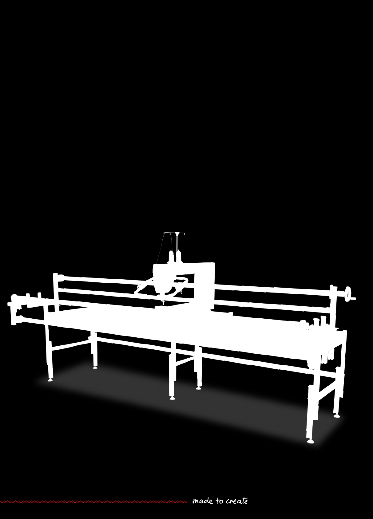
BERNINA Q 24 | Q 20
Frame Mounting Manual
Page 2

Page 3

Edition notice
Edition notice
Text, Setting and Layout
BERNINA International AG
Photos
Patrice Heilmann, Winterthur
BERNINA International AG, Steckborn
Order number
2019-04 en 0365655.10A.04
Copyright
2018 BERNINA International AG
All rights reserved: For technical reasons and for the purpose of product improvements, changes
concerning the features of the machine can be made at any time and without advance notice. The supplied
accessory can vary depending on the country of delivery.
1
Page 4

Table of Contents
Table of Contents
IMPORTANT SAFETY INSTRUCTIONS ................. 3
1 My BERNINA ........................................................ 5
1.1 Further information ................................................ 5
1.2 Content of these instructions ................................. 5
Explanation of symbols ........................................... 5
1.3 Overview of the quilting frame ............................... 6
1.4 Overview of delivery ............................................... 7
1.5 Overview of large parts .......................................... 7
1.6 Overview of small parts .......................................... 8
2 Quilting frame assembly .................................... 12
2.1 Unpacking and checking the delivery ..................... 12
2.2 Recurring steps ...................................................... 12
Fitting the slot nuts ..................................................... 12
Tightening the socket screws ...................................... 13
2.3 Sequence of assembly steps ................................... 13
2.4 Working height adjustment .................................... 13
2.5 Base frame assembly .............................................. 15
Overview components ................................................ 15
Attachting adjustable levelling feet ............................. 16
Attaching the lower cross bar ..................................... 16
Attaching the back bar ............................................... 18
Attaching the front bar ............................................... 21
2.6 Rail support assembly ............................................. 23
Attaching rail supports ................................................ 23
Adapting the rail support for BERNINAQ20 ............... 24
2.7 Tabletop positioning .............................................. 25
Attaching tabletop brackets ........................................ 25
Positioning tabletops .................................................. 25
2.8 Quilting frame levelling .......................................... 26
2.9 Track assembly ....................................................... 27
Attaching the rear track .............................................. 27
Attaching the front track ............................................ 29
2.12 Machine preparation ............................................... 38
Overview ...................................................................... 38
Getting the machine ready ........................................... 41
Attaching the V-wheel units ......................................... 41
Attaching the front stand profile .................................. 42
Attaching the rear stand profile .................................... 44
Positioning the machine on the carriage ....................... 46
Attaching safety brackets ............................................. 47
Fitting rail covers .......................................................... 49
2.13 Take-up rail and dead bar attachment ..................... 50
Attaching the Take-up rail ............................................ 50
Attaching the handwheel to the take-up rail ................ 52
Attaching the dead bar ................................................ 53
2.14 Leader, side clamp, and storage tray attachment ..... 55
General notes on attaching the leaders ........................ 55
Attaching the Back leader ............................................ 55
Attaching the Take-up leader ....................................... 56
Attaching the Top leader .............................................. 57
Attaching the side clamps ............................................ 58
Attaching the storage trays .......................................... 59
2.15 Front handle attachment ......................................... 60
Attaching the front handle unit .................................... 60
Adjusting the width of the handles .............................. 60
Adjusting the handles .................................................. 61
3 Disposal ................................................................ 62
3.1 Quilting frame disposal ........................................... 62
4 Specifications ....................................................... 63
5 Appendix .............................................................. 64
5.1 Differing information for the "Large" quilting frame
................................................................................
64
5.2 Differing information for the "Small" quilting frame
................................................................................
64
Index ..................................................................... 66
2.10 Top and backing rail assembly ................................ 31
Assembling the top rail ............................................... 32
Assembling the backing rail ........................................ 33
2.11 Carriage and park position magnet alignment ........ 35
2
Page 5

Important safety instructions
IMPORTANT SAFETY INSTRUCTIONS
Please observe the following general safety instructions when assembling the
quilting frame. Before using the quilting frame, also read the operating
instructions for the machine from the BERNINA Q Series carefully.
WARNING
To protect persons from injuries:
• The packaging of the quilting frame and the machine is large and heavy. The
packaging should therefore always be carried by at least two adults
together.
• Position the packaging and individual parts so that they cannot fall over.
• Setting up the quilting frame requires at least two adults.
• During assembly of the individual and small parts, ensure that the parts are
kept out of the reach of small children (risk of suffocation).
• During assembly, ensure that your fingers do not get trapped or caught.
• Only use the quilting frame for the purpose described in these assembly
instructions.
• Do not use the quilting frame as a toy.
• The quilting frame can be assembled by children over the age of 8, as well
as by persons with reduced physical, sensory, or mental capacities or with a
lack of experience and knowledge, as long as they are supervised or have
been made aware of the potential hazards.
• Only use accessories recommended by the manufacturer.
• Do not insert any objects into the openings on the quilting frame.
• Keep fingers away from all moving parts. Special caution is required in the
area of the take-up rail, top rail and backing rail, as well as the carriage.
Availability of the instruction manual
The assembly instructions are part of the quilting frame.
• Store the assembly instructions for the quilting frame in a suitable location
near the quilting frame and keep them available to consult.
• If the quilting frame is passed on to third parties, always include the
assembly instructions with the quilting frame.
3
Page 6

Important safety instructions
Proper use
The quilt frame serves as a support for the machines in the Q series and as a
workplace for long arm quilting. Any other use is not considered proper.
BERNINA assumes no liability for consequences resulting from improper use.
4
Page 7

My BERNINA
1 My BERNINA
1.1 Further information
You can find the latest version of your assembly instructions as well as a lot more information about quilting
on our website at http://www.bernina.com
1.2 Content of these instructions
These assembly instructions describe assembly of the "Classic" quilting frame. With certain differences, the
instructions also apply to assembly of the "Large" and "Small" quilting frames. The differences primarily
concern the number of certain parts. You can find information on these differences in the following section:
• Differing information for the "Large" quilting frame (see page64)
• Differing information for the "Small" quilting frame (see page64)
Explanation of symbols
DANGER
WARNING
CAUTION
NOTICE
Labels a high-risk hazard which can lead to serious injuries or potentially even death if not avoided.
Labels a medium-risk hazard which can lead to serious injuries if not avoided.
Labels a low-risk hazard which can lead to minor or moderate injuries if not avoided.
Labels a hazard which can lead to material damage if not avoided.
Tips from BERNINA quilt experts can be found next to this symbol.
Example images are used in these operating instructions for the purposes of illustration. The machines shown
in the images and the accessories shown therefore do not always match the actual items included with your
machine.
5
Page 8

My BERNINA
1
2
3
4
11
10
17
9
14
12
6
5
7
13
1518 16
8
1.3 Overview of the quilting frame
1 Legs, left 10 Cross bar, rear
2 Tabletops 11 Rail support, right
3 Rail support, left 12 Top rail
4 Backing rail 13 Cross bar, bottom
5 Dead bar 14 Legs, right
6 Machine 15 Track, front
7 Take-up rail 16 Legs, center
8 Storage tray 17 Carriage
9 Track, rear 18 Cross bar, front
6
Page 9

My BERNINA
1.4 Overview of delivery
The machines in the BERNINA Q Series for quilting frames are delivered in three packages. Any special
accessories ordered additionally will be supplied in separate packages. These accessories are not taken into
account in these assembly instructions.
Cardboard box Content Size in cm (in) Weight in kg (lb)
1 Q Series machine, including
standard accessories
2 Large parts, tools and
accessories
3 Long parts Approx. 350 × 30 × 24
Approx. 112 × 77 × 42
(44.1 × 30.3 × 16.5)
Approx. 120 × 80 × 70
(47.2 × 31.5 × 27.6)
(137.8 × 11.8 × 9.5)
1.5 Overview of large parts
The delivery contains the following large parts:
Cardbo
ard box
1 1 Machine
2 3 Tabletops
Number Large parts
1 Carriage
Approx. 40
(88.2)
Approx. 75
(165.4)
Approx. 66
(145.5)
3 Legs: Right, left, center
2 Rail supports: Right, left
3 1 Cross bar, bottom
2 Cross bars: Rear, front
2 Tracks: Rear, front
1 Top rail
1 Backing rail
1 Take-up rail
1 Dead bar
7
Page 10

My BERNINA
1.6 Overview of small parts
All small parts such as screws, nuts, washers, etc. that are required for assembly of the standard quilting
frame can be found in cardboard box 2.
The parts are packaged in bags or boxes. We recommend unpacking all parts and then sorting them based
on type. You can use the following tables to check the scope of delivery.
For identification purposes, each part has a code that is included in the list of parts required for the
respective task in the assembly instructions.
Note: The number of items included with the small and the large quilting frame can differ from the details
provided in the following tables. The differences are listed in the appendix. (see page64)
All rights reserved: Changes with regard to the equipment of the machine can be made at any time and
without advance notice for technical reasons and for the purpose of improving the product. The accessories
supplied can also be subject to changes, depending on the country of delivery.
Figure Number Designation Code Tool Use
9 Head cap screw, M8×40 S1 Allen key no.6 Rail support assembly (8 pcs)
Carriage alignment (1 pc.)
3 Head cap screw, M8×50 S2 Torx T30 screwdriver Attaching the lower cross bar
1 Countersunk screw, M5×10 S3 Allen key no.3 Attaching the Take-up rail
2 Head cap screw, M8×50 S4 Allen key no.5 Assembling the Top rail
1 Countersunk screw, M4×45,
black
16 Head cap screw, M4×16 S6 Allen key no.3 Track assembly
4 Button head screw, M5×12 S7 Allen key no.3 Attaching the storage trays
S5 Allen key no.3 Carriage alignment
10 Countersunk screw, M8×14,
black
2 Button head screw, M6×12 S9 Torx T30 screwdriver Carriage alignment
8
S8 Allen key no.5 Positioning tabletops (8 pcs)
Attaching the dead bar (2
pcs)
Page 11

Figure Number Designation Code Tool Use
4 Head cap screw, M5×16 S10 Torx T25 screwdriver Carriage alignment
4 Head cap screw, M6×50 S11 Allen key no.5 Attaching the front bar
My BERNINA
2 Button head self-tapping
S12 Torx T30 screwdriver Attaching the front track
screw, 6.3×22
10 Slot nut, M6, comprising a
SN1 Allen key no.5 Attaching the rear bar
square nut, an M6 serrated
washer and a head cap
screw (M6×12)
Tab.1: Overview of screws
Figure Number Designation Code Tool Use
1 Nut, M4 N1 Carriage alignment
4 Hex nut, M5 N2 Carriage alignment
6 Washer, M10 W1 Attaching adjustable leveling
Attaching the front bar
feet
8 Serrated washer, M8 W2 Rail support assembly
3 Washer, M8 W3 Attaching the lower cross bar
1 Countersunk washer, D25 W4 Attaching the Take-up rail
4 Serrated washer, M6 W5 Attaching the front bar
4 Washer, 5.3/10×1 W6 Carriage alignment
9
Page 12

My BERNINA
Figure Number Designation Code Tool Use
2 Serrated lock washer, M6 W7 Carriage alignment
Tab.2: Overview of washers, nuts
Figure Number Designation Code Tool Use
6 Leveling foot M1 Open-ended wrench no.14 Attaching adjustable leveling
2 Storage tray, black M2 – Attaching the storage trays
feet
1 Handwheel, black, sticker/
M3 Allen key no.3 Attaching the Take-up rail
cover label
1 Locking piece M4 – Attaching the Take-up rail
1 Winder bolt M5 Allen key no.4 Attaching the Take-up rail
2 Setting collar (with three
M6 Allen key no.2 Attaching the backing rail
screwed-in grub screws)
Attaching the Take-up rail
3 Ratchet wheel (with three
M7 Allen key no.2 Attaching the backing rail
screwed-in grub screws)
Attaching the Take-up rail
Attaching the Top rail
1 Magnet, circular M8 – Carriage alignment
10
1 Rubber cap for magnet,
M9 – Carriage alignment
black
8 Metal bracket, black M10 – Positioning tabletops
Page 13

Figure Number Designation Code Tool Use
My BERNINA
14 Self-adhesive felt strips,
black
4 Cover cap for Y rails M12 – Carriage alignment
4 Cover cap for X rails M13 – Carriage alignment
4 Y safety bracket M14 – Carriage alignment
2 X safety bracket M15 – Carriage alignment
4 Bungee cord M16 – Attaching the side clamps
M11 – Positioning tabletops
4 Safety clips M17 – Attaching the side clamps
1 Double-sided adhesive tape M18 – Attaching the side clamps
– 1 Back leader – – Attaching the side clamps
– 1 Top leader – – Attaching the side clamps
– 1 Take-up leader – – Attaching the leaders
Tab.3: Overview of various parts
Figure Number Designation Code
1 Allen key set, nine-piece T1
3 Open-ended wrench:
6×7, 12×14, 13×17
T2
Tab.4: Tools supplied
11
Page 14

Quilting frame assembly
2 Quilting frame assembly
2.1 Unpacking and checking the delivery
> Open the packaging and unpack the individual parts.
> Check the individual parts for damage.
> Check that the delivery is complete.
> If parts are missing or if you have any questions about the assembly, contact your specialist BERNINA
2.2 Recurring steps
The following instructions describe steps that you need to perform repeatedly during assembly of the quilting
frame. These steps are not described in detail each time in the assembly instructions.
Fitting the slot nuts
Slot nuts can be used to securely connect the components of the base frame to one another. A set of slot
nuts (SN1) comprises the slot nut that fits into the slot on the component, a serrated washer and a screw.
> Unscrew the screw from the slot nut.
> Insert the slot nut into the slot near the joint. Ensure that the spring is inside and that the thread can be
dealer immediately.
seen from the outside.
12
> Use the Allen key to slide the slot nut in the slot so that it comes to rest precisely behind the borehole on
the counterpart.
> Place the washer onto the screw.
Page 15

Quilting frame assembly
> Insert the screw through the borehole and screw it into the slot nut.
> Tighten the screw, holding the Allen key by the long end.
Tightening the socket screws
> Always hold the Allen key by the long end when tightening the SN1, S1, S3, S4, S5, S8, and S11 screws.
2.3 Sequence of assembly steps
1. Working height adjustment. (see page13)
2. Base frame assembly. (see page15)
3. Rail support attachment. (see page23)
4. Tabletop positioning. (see page25)
5. Quilting frame levelling. (see page26)
6. Track assembly. (see page27)
7. Top and backing rail assembly. (see page32)
8. Carriage and park position magnet alignment. (see page35)
9. Machine preparation. (see page38)
10.Take-up rail and dead bar attachment. (see page53)
11.Leader, side clamp and storage tray attachment. (see page55)
2.4 Working height adjustment
For optimal ergonomics and the best possible quilt quality, the height of the quilting frame can be adjusted.
To adjust the quilting frame to the optimal working height, the legs must be adjusted to the correct length
before assembling the frame.
13
Page 16

Quilting frame assembly
b
a a
2
1
CAUTION!Do not adjust the height of the quilting frame using the height-adjustable levelling feet.
These are only intended for horizontal alignment of the quilting frame.
Determining the optimal working height
The optimal working height (b) is the height of the lower edge of your elbow when your arm is bent at right
angles. For most people, this is around the height of the navel. The height of the quilting frame must be set
so that the stitch plate on the machine is located at the optimal working height (b).
To adjust the quilting frame to the optimal working height, the legs must be adjusted to the correct length
before
assembling the frame.
On delivery, the quilting frame is set to a working height that suits persons with a height of approximately
162 to 167 cm (5'4" to 5'6").
> For other heights, measure the distance from the lower edge of the elbow to the floor (b) with the arms
at right angles.
> The following table lists the suitable leg lengths for this.
Elbow height b (cm / inches) Leg length a (cm / inches)*
95 / 37 5 / 2
100 / 39 10 / 4 Delivery state
105 / 41 15 / 6
110 / 43 20 / 8
115 / 45 25 / 10
*) Length of the protruding leg profile (without levelling feet).
Comment
Adjusting the leg length
Each leg of the quilting frame comprises two leg segments that can be moved against one another.
14
Page 17

Required parts and tools:
a
a
1
2
3
4
5
• Allen key no.6 (T1)
• Tape measure (not included in the scope of delivery)
Prerequisite:
• The optimal leg length is determined.
> Undo the two locking screws on each leg.
– The two leg segments can be moved against one another.
> Move the lower leg segment until it reaches the leg length determined.
Quilting frame assembly
> Tighten the locking screws.
2.5 Base frame assembly
Overview components
The following figures show the most important pre-assembled parts and components for quilting frame
assembly.
1 Rail support, left 4 Legs, right
2 Legs, left 5 Rail support, right
3 Legs, center
15
Page 18

Quilting frame assembly
Attachting adjustable levelling feet
The adjustable levelling feet are used to level the quilting frame (see page26). To ensure sufficient scope
for precision adjustment of the height, the levelling feet must not be screwed in as far as they can go.
Required parts and tools:
> Place one washer (W1) on each levelling foot (M1).
> Screw one levelling foot onto each leg. To ensure that there is sufficient scope for precision adjustment
• Legs, center
• Legs, left
• Legs, right
• 6× levelling feet (M1)
• 6× washers (W1)
• Open-ended wrench no. 14 (T2)
of the height, set a distance of 5cm (1.96inches) between the lower edge of the profile and the lower
edge of the foot.
Attaching the lower cross bar
Required parts and tools:
• Cross bar, bottom
• Legs, center
• Legs, right
• Legs, left
• 3× head cap screws M8 × 50 (S2)
• 3× washers M8 (W3)
• Allen key no.6 (T1)
Prerequisite:
• Leg length is set.
16
Page 19

Quilting frame assembly
> Lay out large parts in approximately the right position on the floor.
> Place the lower cross bar onto the lower longitudinal bar of the central leg in such a way that the central
borehole is located precisely above the pre-fitted slot nut.
> Place a washer (W3) onto a head cap screw (S2). Tighten the screw.
> Place the left-hand edge of the cross bar onto the lower longitudinal bar of the left leg in such a way that
the borehole is located precisely above the pre-fitted slot nut.
17
Page 20

Quilting frame assembly
> Place a washer (W3) onto a head cap screw (S2). Tighten the screw.
> Place the right-hand edge of the cross bar onto the lower longitudinal bar of the right leg in such a way
that the borehole is located precisely above the pre-fitted slot nut.
> Place a washer (W3) onto a head cap screw (S2). Tighten the screw.
Attaching the back bar
Required parts and tools:
• Cross bar, rear
• 8x slot nuts (SN1)
• Allen key no.5 (T1)
Moving the upper longitudinal bar on the central leg
The upper longitudinal bar on the central leg must be moved so that the rear cross bar can be fitted.
> Use the Allen key (T1) to undo the two screws in the lower slot on the right and left of the front leg and
then push the longitudinal bar slightly forward.
18
Page 21

Quilting frame assembly
Positioning the rear cross bar
> Place the cross bar onto the central leg in such a way that the inserted slot nuts are located in the lower
slot and point inward. The "TOP" sticker faces upward.
> Move the inserted slot nuts in such a way that there are the same number of slot nuts to the right and
the left of the central leg.
> Insert the rear cross bar into the slot of the left leg in such a way that the upper edges of the rear cross
bar and the left-hand longitudinal bar are at the same height.
19
Page 22

Quilting frame assembly
> Insert the rear cross bar into the slot of the right leg in such a way that the upper edges of the rear cross
Attaching the rear cross bar to the right and left leg
Carry out the following tasks on both sides.
> Attach a slot nut (SN1) to the top edge of the cross bar. (see page12)
> Check to ensure that the cross bar and longitudinal bar are at the same height.
> If necessary, align the rear cross bar.
> Tighten the screw. (see page13)
bar and the right-hand longitudinal bar are at the same height.
20
> Attach a slot nut (SN1) to the bottom edge of the cross bar.
Page 23

Quilting frame assembly
Attaching the rear cross bar to the central leg
> Push the upper longitudinal bar on the central leg backward again so that it fits into the lower slot on the
internal surface of the cross bar.
> Attach one slot nut (SN1) each in the lower slot of the cross bar to the right and the left of the
longitudinal bar.
> Attach one slot nut (SN1) each in the slot on the lower edge of the cross bar to the right and the left of
the central leg.
Attaching the front bar
Required parts and tools:
• Cross bar, front
• 2× slot nuts (SN1)
• 4× head cap screws M6×50 (S11)
• 4× serrated washers M6 (W5)
• Allen key no.5 (T1)
Positioning the front cross bar
> Place the cross bar onto the central leg in such a way that the inserted slot nuts are located in the lower
slot and point inward. The "TOP" sticker faces upward.
21
Page 24

Quilting frame assembly
> Move the inserted slot nuts in such a way that there are the same number of slot nuts to the right and
Attaching the front cross bar to the right and left leg
Carry out the following tasks on both sides.
> Place one serrated washer (W5) onto each of two head cap screws (S11).
> On the upper longitudinal bar, push one head cap screw into the top front borehole from the outside.
> Guide the screw into the lateral edge of the cross bar and tighten it (see page13).
> Guide the second head cap screw through the lower borehole and secure it in the lateral edge of the
the left of the central leg.
cross bar.
22
Attaching the front cross bar to the central leg
> Attach one slot nut (SN1) each in the lower slot of the cross bar to the right and the left of the
longitudinal bar.
Page 25

Quilting frame assembly
2.6 Rail support assembly
Attaching rail supports
Required parts and tools:
• Rail support, left
• Rail support, right
• 8× head cap screws M8×40 (S1)
• 8× serrated washers M8 (W2)
• Allen key no.6 (T1)
Carry out the following tasks on both sides.
> Hold the rail support against the leg from the outside in such a way that the head cap screws(S1) can be
screwed into the pre-fitted slot nuts on the rail support.
> Place one serrated washer (W24) onto each of the four head cap screws (S1).
> Screw the head cap screws(S1) into the screw holes on the leg from the inside and only tighten them to
the point where the rail support can still be moved.
> Slide the rail support downward and forward until the two metal brackets (M10) rest on the longitudinal
bar of the leg.
23
Page 26

Quilting frame assembly
> Tighten the head cap screws(S1) (see page13).
Adapting the rail support for BERNINAQ20
Required parts and tools:
Carry out the following tasks on both sides.
> Undo the two screws on the top of the rail support.
• Allen key no.6 (T1)
24
> Push the front part of the movable bar toward the vertical profile as far as it will go.
> Tighten the two screws.
Page 27

Quilting frame assembly
2.7 Tabletop positioning
Attaching tabletop brackets
Attach a total of eight metal brackets as supports for the tabletops, comprising four in the rear cross bar and
four in the front cross bar.
Required parts and tools:
• 8× metal brackets (M10)
• 8× countersunk screws M8×14 (S8)
• Allen key no.5 (T1)
Carry out the following tasks for all metal brackets.
> Hold the metal bracket (M10) in front of a slot nut in the cross bar so that the screw hole is positioned
directly above the thread.
> Insert a countersunk screw(S8) into the screw hole and tighten it, but only to the point where the metal
bracket (M10) can still be moved.
Positioning tabletops
Required parts and tools:
• 14× felt strips (M11)
• 3× tabletops
• Allen key no.5 (T1)
> Attach felt strips(M11) to all metal brackets(M10), including the pre-assembled ones on the legs.
> Attach two felt strips to the upper longitudinal bar of the central leg.
25
Page 28

Quilting frame assembly
> Position the metal brackets(M10) so that two tabletops rest on each bracket. Tighten the screws (see
> Place the tabletops onto the metal brackets(M10) so that the tabletops are stable.
page13).
> If necessary, carefully undo the metal brackets(M10) and reposition them.
2.8 Quilting frame levelling
To allow the machine to move smoothly on the quilting frame, the quilting frame must be aligned perfectly
horizontally using the levelling feet after assembly.
Required parts and tools:
• Open-ended wrench no. 17 (T2)
• Spirit level (not included in the scope of delivery)
> Move the quilting frame into the final position for quilting.
> Screw in the levelling feet(M1) on the central leg until they no longer touch the floor.
> Use the spirit level to check the horizontal alignment of the quilting frame. If necessary, shorten the
lateral leg lengths by screwing in the levelling feet(M1) or extend them by unscrewing the feet.
> As soon as the quilting frame has been levelled, unscrew the levelling feet(M1) on the central leg so that
they touch the ground firmly and the quilting frame is well supported.
26
Page 29

> Tighten the counternuts on all six legs.
2.9 Track assembly
Attaching the rear track
Quilting frame assembly
Required parts and tools:
• 8x head cap screws M4×16 (S6)
• 1× track
• 2× black plastic inserts
• Allen key no.3 (T1)
> Pull the two black plastic inserts out of the tracks.
> Insert the head cap screws(S6) into the holes on the track one after the other.
27
Page 30

Quilting frame assembly
> Push the two black plastic inserts back into the track.
> Place the track onto the rear cross bar so that the screw holes(1) are precisely above the threads(2) of
the pre-fitted rail and the flat part of the track is pointing inward.
> Only tighten the inserted head cap screws(S6) to the point that the track can still be moved.
28
Page 31

Quilting frame assembly
> To ensure that the carriage later rests optimally on the tracks, pull the track outwards and then tighten all
head cap screws(S6).
Attaching the front track
Required parts and tools:
• 8× head cap screws M4×16 (S6)
• 2× button head self-tapping screws 6.3×22 (S12)
• 1× track
• 2× black plastic inserts
• Allen key no.3 (T1)
• Torx screwdriver no.T30 (included in the box with the machine)
> Pull the two black plastic inserts out of the tracks.
> Insert the head cap screws(S6) into the holes on the track one after the other.
29
Page 32

Quilting frame assembly
> Push the two black plastic inserts back into the track.
> Place the track onto the front cross bar so that the screw holes(1) are precisely above the threads(2) of
the pre-fitted rail and the flat part of the track is pointing inward.
> Only tighten the inserted head cap screws(S6) to the point that the track can still be moved.
30
Page 33

Quilting frame assembly
1
2
1
2
3
3
> To ensure that the carriage later rests optimally on the tracks, pull the track outwards and then tighten all
head cap screws(S6).
> Screw in one button head self-tapping screw (S12) on each of the two sides of the track.
2.10 Top and backing rail assembly
The top rail and backing rail are fitted to the rail supports at the front.
1 Support, top rail 2 Support, backing rail
3 Support, take-up rail
NOTICE!Leaders are already fitted in some of the following images. In these assembly instructions,
attaching the leaders is only described later. Always attach the rails without leaders.
31
Page 34

Quilting frame assembly
Assembling the top rail
Required parts and tools:
> Push the ratchet wheel(M7) over the right-hand end of the top rail so that the teeth are pointing
• Top rail
• Ratchet wheel (M7)
• 2× head cap screws M8×50 (S4)
• Allen key no.2 and no.6 (T1)
forward when viewed from the front of the quilting frame.
> Hold the top rail and inner bar with the pre-fitted plastic cap precisely in front of the screw hole on the
lower rail bracket of the right-hand rail support.
> Insert the head cap screw(S4) through the screw hole and tighten it.
32
> Repeat the last two steps on the left-hand side.
> Push the ratchet wheel(M7) under the pawl as close as possible to the rail support. However, the ratchet
wheel must not brush against the rail support.
Page 35

Quilting frame assembly
> Tighten the pre-fitted grub screws so that the rail and ratchet wheel are securely connected to one
another.
Assembling the backing rail
Required parts and tools:
• Backing rail
• 1× setting collar (M6)
• 1× ratchet wheel (M7)
• Allen key no.2 (T1)
> Push the setting collar (M6) over the left-hand end of the backing rail.
33
Page 36

Quilting frame assembly
> Push the ratchet wheel(M7) over the right-hand end of the backing rail so that the teeth are pointing
> Push both ends of the backing rail into the upper rail brackets of the rail supports.
> Align the backing rail centrally.
> Push the setting collar(M6) up close to the left-hand rail support. The setting collar must not, however,
> Tighten the pre-fitted grub screws so that the rail and setting collar are securely connected to one
backward when viewed from the front of the quilting frame.
brush against the rail support.
another.
> Push the ratchet wheel(M7) under the pawl as close as possible to the rail support. However, the ratchet
wheel must not brush against the rail support.
> Tighten the pre-fitted grub screws so that the rail and ratchet wheel are securely connected to one
another.
34
Page 37

Quilting frame assembly
2.11 Carriage and park position magnet alignment
Positioning the carriage
Required parts and tools:
• Carriage
> Position the carriage on the tracks so that the hole for the park position magnet(M8) is pointing to the
left when viewed from the front.
> Guide the carriage along the tracks, while checking the contact of the wheels to the tracks with your
fingers.
> If the carriage does not slide smoothly over the tracks, or if not all wheels are in contact with the tracks
at all times, the carriage needs to be realigned.
Aligning the carriage
Required parts and tools:
• Allen key no.4 (T1)
35
Page 38

Quilting frame assembly
> Undo the four screws to align the carriage.
> Align the carriage so that it slides smoothly over the tracks along the entire length of the quilting frame
> Tighten the screws.
Attaching the park position magnet
and all wheels are in contact with the tracks at all times.
Required parts and tools:
• Magnet, circular (M8)
• Rubber cap, black (M9)
• 1x head cap screw M8×40 (S1)
• Countersunk screw M4×45 (S5)
• Nut M4 (N1)
• Allen keys no.2.5 and no.6 (T1)
• Open-ended wrench no.7 (T2)
> Push the countersunk screw(S5) first through the magnet (M8) and then through the rear hole. Position
the nut(N1) from the other side and hold it in place with the open-ended wrench. Tighten the screw.
36
Page 39

Quilting frame assembly
> Press the black rubber cap (M9) over the magnet (M8).
> Screw the head cap screw(S1) into the pre-mounted slot nut in the rear vertical profile of the left-hand
rail support, but only tighten it slightly so that it can still be moved.
> Push the carriage into the park position. Check whether the park position magnet(M8) touches the head
cap screw(S1).
> If necessary, adjust the height of the head cap screw(S1) and then tighten it.
37
Page 40

Quilting frame assembly
2.12 Machine preparation
Overview
Required parts and tools:
• BERNINA Q Series machine
• 2× stand profiles
• Accessories for stand profiles
• 4× V-wheel units (P16) (carriage accessories, cardboard box 2)
• Allen key no.5 (T1)
• Torx screwdrivers (T20 and T25) (included in the box with the BERNINA Q Series machine)
• Slotted screwdriver, medium-sized (not included in the scope of delivery)
Figure NumberDesignation Code Tool Use
1 Stand profile, front P1 Attaching the front stand
profile
1 Stand profile, rear P2 Attaching the rear stand
profile
1 Damping mat P3 Attaching the front stand
profile
1 Aluminum plate P4 Attaching the rear stand
profile
1 Circular sleeve P5 Attaching the front stand
profile
1 Threaded bolt, short P6 Attaching the front stand
profile
1 Spring washer P7 Attaching the front stand
profile
38
1 Washer P8 Attaching the front stand
profile
1 Serrated lock washer P9 Attaching the rear stand
profile
Page 41

Quilting frame assembly
Figure NumberDesignation Code Tool Use
1 Head cap screw P10 Torx T25 screwdriver Attaching the rear stand
profile
1 Head cap screw P11 Allen key no.5 (T1) Attaching the front stand
profile
2 Head cap screw P12 Torx T20 screwdriver Attaching the rear stand
profile
1 Washer, thick, small P13 Attaching the front stand
1 O-ring P14 Attaching the front stand
1 Washer, thick, large P15 Attaching the front stand
4 V-wheel units P16 Allen key no.4 (T1) Attaching the V-wheel units
Tab.5: Overview of parts for machine assembly
profile
profile
profile
39
Page 42

Quilting frame assembly
P15
P13
P3
P6
P7
P1
P11 P8 P16P16 P10 P9
P2
P4
P12
P12
P16P16 P14P5
Overview of assembly
40
Important notes on the stand profiles
Both stand profiles have a round hole on one side and a slotted opening on the other side for attaching the
V-wheels. The slotted opening allows the V-wheels to be subsequently aligned, so that they rest perfectly on
the tracks of the carriage. Please therefore make sure that the slotted opening on both stand profiles is on
the same side of the machine after assembly.
The front stand profile differs from the rear stand profile due to a plastic stud on the underside, i.e. the stand
profile with the plastic stud must be fitted at the front of the machine.
Page 43

Sequence of assembly steps
1. Getting the machine ready (see page41)
2. Attaching the V-wheel units (see page41)
3. Attaching the front stand profile (see page42)
4. Attaching the rear stand profile (see page44)
5. Positioning the machine on the carriage (see page46)
6. Attaching safety brackets (see page47)
7. Fitting rail covers (see page49)
Getting the machine ready
Quilting frame assembly
CAUTION
The machine can easily tip over without stand profiles
Risk of injury and damage to the machine.
> Carefully put the machine in a position where it is stable.
> Lay the machine down on its side at the edge of a fixed base, such as a tabletop.
Attaching the V-wheel units
Attach the V-wheel units to both stand profiles.
Required parts and tools:
• 4x V-wheel units (P16)
• Stand profile, front (P1)
• Stand profile, rear (P2)
• Allen key no.4 (T1)
• Tape measure (not included in the scope of delivery)
Perform the following work for both stand profiles.
> Remove the screws and washers from the V-wheel units(P16).
41
Page 44

Quilting frame assembly
> Position the V-wheel unit under the outer round hole, insert the screw from above and then tighten it.
> On the other side of the profile, position the V-wheel unit(P16) below the slot so that the distance from
> Insert the screw and washer from above, but only tighten the screw slightly so that the V-wheel unit can
the left-hand screw head to the right-hand screw head is approximately28cm(11inches).
still be moved.
NOTICE
Attaching the front stand profile
Machine damage due to undoing screws on the underside of the machine
Parts of the machine can fall out.
> Do not undo any screws on the underside of the machine.
Assembling the front stand profile
Required parts and tools:
• Stand profile, front (P1)
• Damping mat (P3)
• Circular sleeve (P5)
• Threaded bolt (P6)
• Spring washer (P7)
• Washer (P8)
• Head cap screw (P11)
• Washer, thick, small (P13)
• O-ring (P14)
• Washer, thick, large (P15)
42
Page 45

Quilting frame assembly
• Slotted screwdriver, medium-sized (not included in the scope of delivery)
> Push the spring washer(P7) over the thread on the short threaded bolt(P6).
> Screw the threaded bolt into one of the two smaller holes in the center of the front stand profile and
tighten it using the slotted screwdriver.
> Hold the long screw (P11) by its head and then push the washer (P8), black O-ring (P14) and circular
sleeve(P5) onto the screw (P11) one by one in sequence. Position the circular sleeve(P5) so that the
chamfer points downward toward the head of the screw (P11).
> Guide the long screw into the large hole in the plastic stud on the stand profile from below.
> Place the blue damping mat(P3) onto the screw from above so that the lateral recess encircles the
threaded bolt.
> Push the large, thick washer(P15) and the small, thick washer(P13) onto the screw in sequence.
Attaching the front stand profile
Required parts and tools:
43
Page 46

Quilting frame assembly
Prerequisite:
• The machine is on its side (see page41).
> Screw the screw(P11) into the thread on the front slot nut, but only tighten it slightly so that the profile
> Move the stand profile so that the arrow tip printed on the machine profile touches the edge of the
> Tighten the screw(P11).
• Assembled stand profile
• Allen key no.5 (T1)
can still be moved.
damping mat(P3).
NOTICE
Attaching the rear stand profile
Machine damage due to undoing screws on the underside of the machine
Parts of the machine can fall out.
> Do not undo any screws on the underside of the machine.
Required parts and tools:
• Stand profile, rear (P2)
• Aluminum plate (P4)
• Washer (P9)
• Head cap screw (P10)
• 2x head cap screws (P12)
• Torx T20 and T25 screwdrivers
> Place the aluminum plate(P4) onto the center of the rear stand profile from above.
44
Page 47

Quilting frame assembly
> Insert the two screws(P12) on the right and the left and tighten them using the Torx T20 screwdriver.
> Push the screw(P10) with the washer (P9) through the central hole from below.
> Align the stand profile so that the V-wheel unit which is fitted in the slotted hole is on the same side as
with the front stand profile (top or bottom).
> Use the T25 Torx screwdriver to screw the screw into the thread on the rear slot nut, but only tighten it
slightly so that the profile can still be moved.
> Check to ensure that the two heads of the screws(P12) are sunk in the slot on the underside of the
machine.
– The stand profile can still be moved, but not rotated.
> Move the stand profile so that the arrow tip printed on the machine profile touches the edge of the
aluminum plate (P4).
> Tighten the screw(P10).
45
Page 48

Quilting frame assembly
Positioning the machine on the carriage
CAUTION
Risk of injury from improper transport
Risk of injury and damage to the machine.
> Position the machine on the carriage with the help of another person.
> Leave the machine in the park position until the dead bar and take-up rail have been fitted.
Required parts and tools:
• Machine with stand profiles fitted
• 4x lateral cover caps (M13)
• Allen key no.4 (T1)
> Position the machine on the carriage with the help of another person.
> Check to ensure that the machine can be moved freely along the entire length of the carriage and that
all wheels are in contact with the carriage at all times.
> If necessary, readjust the position of the V-wheel units(P16) and then tighten the screws.
> Attach the lateral cover caps(M13) to the ends of the stand profiles.
46
Page 49

Quilting frame assembly
> Carefully push the machine up to the left-hand rail support and into the park position.
Attaching safety brackets
The machine is secured from tipping over with two types of safety brackets:
• Y safety brackets secure the machine on the carriage and are fitted to the machine's stand profiles.
• X safety brackets secure the carriage on the quilting frame and are fitted to the carriage.
Attaching Y safety brackets
Attach the four Y safety brackets to the two stand profiles of the machine on both sides.
Required parts and tools:
• 4× Y safety brackets (M14)
• 4× washers 5.3/10×1 (W6)
• 4× head cap screws Torx M5×16 (S10)
• 4× hex nuts M5 (N2)
• Torx screwdriver (T25)
• Open-ended wrench no.8 (T2)
> Guide one head cap screw (S10) with washer attached (W6) through the borehole behind the rail in the
stand profile from above.
> Push one Y safety bracket (M14), with the slot facing upward, over the screw from below.
47
Page 50

Quilting frame assembly
1mm
> Loosely tighten the hex nut (N2) from below, with the ribbed surface facing upward.
> Push the Y safety bracket (M14) all the way up to the rail and then pull it approximately 1 mm back.
– The Y safety bracket does not touch the rail.
48
> Hold the threaded nut securely with the open-ended wrench and then tighten the head cap screw (S10).
> Attach the other three Y safety brackets (M14) the same way.
Page 51

Quilting frame assembly
Checking the position of the Y safety brackets
> Move the machine forward and backward.
> Check whether the Y safety brackets (M14) brush against the wheels.
> If they do, pull the Y safety brackets approximately 1 mm away from the wheels.
> Check whether the wheels become jammed.
> If they do, undo the head cap screw (S10) slightly.
> Check whether the machine can be lifted off the carriage.
> If it can, move the Y safety brackets closer to the wheels.
Attaching X safety brackets
Required parts and tools:
• 2× X safety brackets (M15)
• 2× serrated lock washers M6 (W7)
• 2× button head screws Torx M6×12 (S9)
• Torx screwdriver (T30)
> Push the serrated lock washer (W7) over the button head screw (S9). Screw down one X safety bracket
(M15) vertically to the carriage in the center at the back.
> Push the serrated lock washer (W7) over the button head screw (S9). Screw down the second X safety
bracket (M15) vertically to the carriage in the center at the front.
Checking the position of the X safety brackets
> Push the machine along the entire length of the quilting frame.
> Check whether the X safety brackets (M15) brush against anything.
> If they do, undo the button head screw (S9) slightly.
> Check whether the machine can be lifted off the quilting frame with the carriage.
> If it can, tighten the button head screw (S9) further.
Fitting rail covers
The rail covers are used to prevent your fingers getting caught or trapped.
Required parts and tools:
• 4x rail covers (M12)
49
Page 52

Quilting frame assembly
> Attach the rail covers to the ends of the rail pair brackets on the carriage, pressing them as far as they
2.13 Take-up rail and dead bar attachment
Attaching the Take-up rail
will go.
CAUTION
Risk of injury from falling machine
Risk of injury and damage to the machine.
> Leave the machine in the park position until the dead bar and the take-up rail have been fitted.
> Always take care when moving the machine or carriage.
Required parts and tools:
• Take-up rail
• 1x setting collar (M6)
• 1× ratchet wheel (M7)
• Allen key no.2 (T1)
> Push the setting collar (M6) over the left-hand end of the take-up rail.
50
Page 53

Quilting frame assembly
> Push the ratchet wheel(M7) over the right-hand end of the take-up rail so that the teeth of the ratchet
wheel are pointing backward when viewed from the front of the quilting frame.
> Guide the take-up rail through the neck of the machine.
> Guide the two ends of the take-up rail through the rear rail brackets of the rail supports.
> Align the take-up rail centrally.
> Push the setting collar(M6) up close to the left-hand rail support. The setting collar must not, however,
brush against the rail support.
> Tighten the pre-fitted grub screws so that the rail and setting collar are securely connected to one
another.
> Slide the ratchet wheel(M7) under the pawl as close as possible to the rail support.
51
Page 54

Quilting frame assembly
> Tighten the pre-fitted grub screws so that the rail and ratchet wheel are securely connected to one
Attaching the handwheel to the take-up rail
Required parts and tools:
another.
• Handwheel (M3)
• Locking piece (M4)
• Winder bolt (M5)
• Countersunk screw M5x10 (S3)
• Countersunk washer D25 (W4)
• Sticker, round (included with the M3 handwheel)
• Allen keys no.3 and no.4 (T1)
> Remove and dispose of the yellow plastic cap from the right-hand end of the take-up rail.
> Insert the locking piece(M4) into the recess on the end of the take-up rail.
> Attach the handwheel(M3) precisely to the protruding end.
52
Page 55

Quilting frame assembly
> Push the countersunk screw washer(W4) onto the countersunk screw(S3).
> Insert the screw into the screw hole and tighten it carefully.
> Cover the countersunk screw(S3) with a sticker.
CAUTION
> Screw the winder bolt (M5) to the handwheel (M3).
Attaching the dead bar
Risk of injury from falling machine
Risk of injury and damage to the machine.
> Leave the machine in the park position until the dead bar and the take-up rail have been fitted.
> Always take care when moving the machine or carriage.
Required parts and tools:
• Dead bar
53
Page 56

Quilting frame assembly
> Guide the dead bar through the neck of the machine with the rounded off side facing backward.
> Carry out the following tasks on both sides.
> Position the dead bar behind the pre-fitted rail support bracket so that the slot nut in the dead bar sits
• 2x countersunk screws M8x14 (S8)
• Allen key no.5 (T1)
precisely behind the screw hole in the bracket.
> Insert the countersunk screw(S8) into the screw hole and tighten it.
Checking/adjusting the height of the dead bar
The dead bar must be attached at the correct height relative to the machine.
If the dead bar is attached too low, the machine will brush when moving. If it is attached too high, the
distance between the material and the BSR sensors is too great. The sensors cannot measure the movement
of the machine correctly and the stitch length is not adjusted correctly.
The dead bar is attached at the optimal height when a no. 6 (T1) Allen key just fits between the dead bar
and the machine.
54
Required parts and tools:
• Allen key no.5 (T1)
• Allen key no.6 (T1)
> To check the height of the dead bar, first move the machine to the left-hand edge of the quilting frame.
> Place Allen key no. 6 (T1) between the machine and the dead bar.
> If the distance between the dead bar and the Allen key is too great or too small, adjust the height of the
dead bar.
> To adjust the height of the dead bar, undo the countersunk screw on the pre-fitted bracket in the rail
support until the bracket can be moved.
> Move the bracket so that the dead bar just touches the no. 6 Allen key (T1) on the machine.
Page 57
Quilting frame assembly
TOP
BACK
TAKE-UP
1
2
3
4
> Tighten the countersunk screw.
> Remove Allen key no.6 (T1).
> Move the machine to the right-hand edge of the quilting frame.
> Repeat the test and height adjustment process.
2.14 Leader, side clamp, and storage tray attachment
General notes on attaching the leaders
• Each leader has one printed and one unprinted side.
• Each leader must be attached securely to the center of the respective rail.
• All leaders are attached using double-sided adhesive tape.
• The leaders are wound onto the rails in different directions.
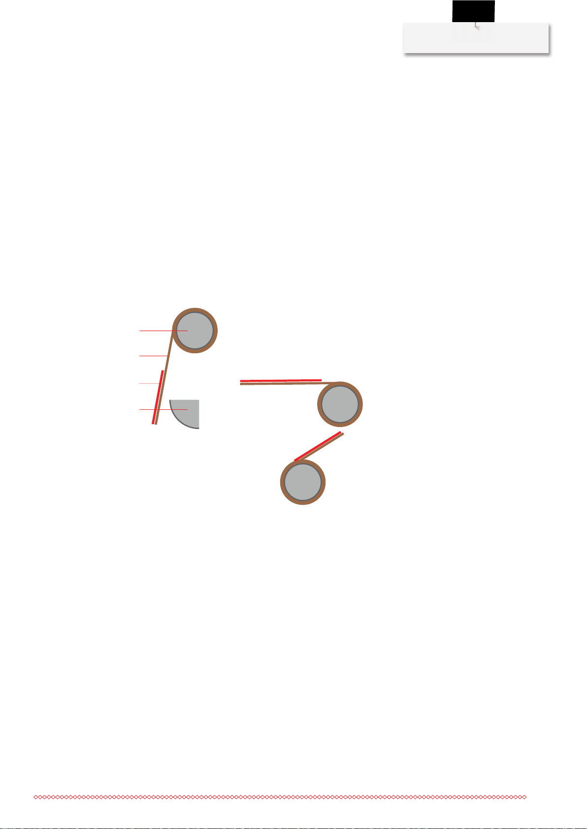
Check the following figure to see how the various leaders need to be attached to their respective rails.
Printed side facing up or down, clockwise or anticlockwise winding direction.
Fig.1: Rails, viewed from the left-hand side of the quilting frame
1 Rail 3 Printed side (red)
2 Leader 4 Dead bar
Sequence of assembly steps
Attach the leaders in the following sequence:
1. Attaching the back leader
2. Attaching the take-up leader
3. Attaching the top leader
Attaching the Back leader
Required parts and tools:
• Back leader
• Double-sided adhesive tape (M18)
• Pencil (not included in the scope of delivery)
• Tape measure (not included in the scope of delivery)
55
Page 58

Quilting frame assembly
> Determine the center of the backing rail using the tape measure and mark this position with a pencil.
> Measure and then use a pencil to mark out a point 155 cm(61inches) to the left and the right of the
> Attach double-sided adhesive tape (M18) from the left-hand marking all the way to the right-hand
marked center.
marking. Be sure to attach the tape straight without any kinks.
> Remove the protective film on the top of the adhesive tape.
> Unfold the back leader so that the material is suspended between the rail and the quilting frame and the
printed side is pointing backward toward the quilting frame.
> Position the center line of the back leader (dark broken line) on the marked center of the backing rail.
> Attach the leader to the adhesive tape, working from the center outward to the left and right. Make sure
you guide the edge of the material precisely along the edge of the adhesive tape.
> Press the leader firmly onto the adhesive tape and roll it up.
> Trim any excess adhesive tape.
56
Attaching the Take-up leader
Required parts and tools:
• Take-up leader
• Double-sided adhesive tape (M18)
• Pencil (not included in the scope of delivery)
• Tape measure, quilting guide or ruler (not included in the scope of delivery)
Page 59

Quilting frame assembly
> To mark the center of the take-up rail, unroll the back leader. Using a quilting guide, first transfer the
center of the back leader onto the dead bar and from there onto the take-up rail. Make sure that
everything is aligned correctly at right angles.
> Fit the take-up leader from the back of the quilting frame.
> Measure and then use a pencil to mark out a point 155 cm(61inches) to the left and the right of the
marked center.
> Attach double-sided adhesive tape (M18) from the left-hand marking all the way to the right-hand
marking. Be sure to attach the tape straight without any kinks.
> Remove the protective film on the top of the adhesive tape.
> Unfold the take-up leader so that the material is suspended between you and the rail and the printed
side is pointing toward you.
> Position the center line of the take-up leader (dark broken line) on the marked center of the take-up rail.
> Attach the leader to the adhesive tape, working from the center outward to the left and right. Make sure
you guide the edge of the material precisely along the edge of the adhesive tape.
> Press the leader firmly onto the adhesive tape and roll it up.
> Check to ensure that the center of the take-up leader and the back leader line up precisely. If necessary,
reposition the take-up leader.
> Trim any excess adhesive tape.
Attaching the Top leader
Required parts and tools:
• Top leader
• Double-sided adhesive tape (M18)
• Pencil (not included in the scope of delivery)
• Tape measure (not included in the scope of delivery)
> Fit the top leader from the front of the quilting frame.
> To mark the center of the top rail, unroll the back leader and pull it straight to the top rail.
57
Page 60

Quilting frame assembly
> Transfer the center position of the unrolled back leader onto the top rail.
> To make it easier to fit the top leader, swing the top rail upward.
> Measure and then use a pencil to mark out a point 155 cm(61inches) to the left and the right of the
> Attach double-sided adhesive tape (M18) from the left-hand marking all the way to the right-hand
> Unfold the top leader so that the material is suspended between you and the rail and the printed side is
> Position the center line of the top leader (dark broken line) on the marked center of the top rail.
> Attach the leader to the adhesive tape, working from the center outward to the left and right. Make sure
> Press the leader firmly onto the adhesive tape and roll it up.
> Check to ensure that the center of the top leader and the back leader line up precisely. If necessary,
> Trim any excess adhesive tape.
> Swing the top rail back down again.
marked center.
marking. Be sure to attach the tape straight without any kinks.
pointing toward you.
you guide the edge of the material precisely along the edge of the adhesive tape.
reposition the top leader.
Attaching the side clamps
Required parts and tools:
• 4x bungee cords (M16)
• 4x safety clips (M17)
> Guide the bungee cord(M16) through the bracket on the left-hand rail support from inside to outside.
> Attach the safety clip (M17) to the end of the bungee cord (M16).
58
Page 61

> Fix the bungee cord (M16) in the bracket.
> Fit the remaining side clamps in the same way.
Attaching the storage trays
Required parts and tools:
• 2× storage trays (M2)
• 4× button head screws M5x12 (S7)
• Allen key no.3 (T1)
Quilting frame assembly
Two slot nuts are pre-fitted in the slot below the brackets of the side clamps.
Carry out the following tasks on both sides.
> Hold the storage tray (M2) in front of the slot.
> Slide the two pre-fitted slot nuts so that they are behind the holes on the storage tray.
> Insert two button head screws (S7) into the holes on the storage tray and tighten them.
59
Page 62

Quilting frame assembly
1
2.15 Front handle attachment
Attaching the front handle unit
> Screw the handle unit behind the head of the machine with the two screws from below so that the
locking levers point backward.
> Insert the cable of the handle unit into the connection at the back on the head of the machine.
Adjusting the width of the handles
NOTICE!To ensure that the thread does not get caught up on the locking lever when winding,
always adjust the locking levers so that they point vertically downward when clamped.
Carry out the following tasks on both sides.
> Swing up the locking lever on the bracket of the handle.
> Move the handle to the side until the required handle width has been reached.
> Adjust the inclination of the handle so that the handle is at a suitable height.
> Only tighten the locking ring (1) to a point where the locking lever can still be swung down with force.
60
Page 63

> Swing the locking lever down.
– The handle is now fixed and the locking lever is pointing downward.
Adjusting the handles
> To adjust the handles, swing up the locking lever on both sides.
Quilting frame assembly
> To adjust the length of the handle, pull the handle out of the bracket or push it into the bracket.
> To adjust the angle of the handle, rotate the handle until a comfortable angle has been reached.
> Close the locking lever.
61
Page 64

Disposal
3 Disposal
3.1 Quilting frame disposal
BERNINA International AG is committed to environmental protection. We make every effort to increase the
environmental friendliness of our products by continually improving their design and production technology.
If you no longer require your quilting frame, please clean it, sort the components according to material and
then dispose of these in line with local regulations and legislation.
Do not dispose of the quilting frame in household waste. If you are in any doubt, first dismantle the quilting
frame and then take it to your nearest BERNINA specialist.
62
Page 65

4 Specifications
B
C
Dimensions of the quilting frame
Specifications
"Classic" quilting frame "Large" quilting frame "Small" quilting frame
Length (A) 12' (3.60 m) 13' (4 m) 9' (2.75 m)
Width (B) 3.9' (1.20 m) 3.9' (1.20 m) 3.9' (1.20 m)
Height (C) 5.6' (1.70 m) 5.6' (1.70 m) 5.6' (1.70 m)
63
Page 66

Appendix
5 Appendix
5.1 Differing information for the "Large" quilting frame
Overview of large parts (see page7)
5x tabletops: 3× large, 2× small
Overview of small parts (see page8)
• 12x metal brackets (M10)
• 16x felt strips (M11)
• 12x countersunk screws M8x14 (S8)
Attaching tabletop brackets (see page25)
> Fit the 12 metal brackets (M10) with 12 countersunk screws M8x14 (S8).
Positioning tabletops (see page25)
> Attach the 16 felt strips (M11).
> Position three large tabletops in the center, with one small tabletop each on the right and the left.
Attaching the leaders (see page55), (see page56), (see page57)
In the step entitled «Measure and then use a pencil to mark out a point 155 cm/61inches to the left and the
right of the marked center.»
, use the following values: 170cm/67inches
5.2 Differing information for the "Small" quilting frame
General overview (see page6)
Point 16 «Legs, center» is no longer applicable.
Overview of large parts (see page7)
Just two legs, on the right and the left
Overview of small parts (see page8)
• 12× head cap screws M4×16 (S6)
• 2× head cap screws M8 × 50 (S2)
• 4× slot nuts (SN1)
• 4× washers (M10)
• 2× washers M8 (W3)
• 4× leveling feet
Attaching adjustable leveling feet (see page16)
64
No legs, center, only four leveling feet (M1) and washers (W1)
Overview of assemblies (see page15)
Point 3 «Legs, center» is no longer applicable
Attaching the lower cross bar (see page16)
Just two legs, on the right and the left
Page 67

Appendix
Just two head cap screws M8 × 50 (S2)
Just two washers M8 (W3)
Do not perform any steps in the instructions that affect the central leg.
Attaching the rear cross bar (see page18)
• Just four 4× slot nuts (SN1) are required
• Do not carry out the tasks described in the instructions entitled «Moving the upper longitudinal bar on
the central leg»
• Work described in the instructions entitled «Positioning the rear cross bar»: Do not perform steps 1 and
2.
Step 4 new: «
are located in the lower slot and point inward, and the "TOP" sticker faces upward. ....»
• Do not perform the work described in the instructions entitled «Fitting the rear cross bar on the central
leg»
.
.
Insert the rear cross bar into the slot on the left leg in such a way that the inserted slot nuts
Attaching the front cross bar (see page21)
• No slot nuts required.
• Do not carry out the tasks described in the instructions entitled «Fitting the front cross bar on the central
leg»
.
Quilting frame levelling (see page26)
Do not carry out the tasks described in step 2 or step 4 of the instructions.
Attaching the rear track (see page27) | Attaching the front track (see page29)
12× head cap screws M4×16 (S6) required.
Attaching the leaders (see page55), (see page56), (see page57)
In the step entitled «Measure and then use a pencil to mark out a point 155 cm/61inches to the left and the
right of the marked center»
, use the following values: 108cm/43inches.
65
Page 68

Index
Index
A
Adjusting the handles 61
Adjusting the working height 13
Assembling the base frame 15
Assembling the machine 38
Attaching side clamps 58
B
Backing rail
Attaching the leaders 55
Fitting 33
C
Carriage
Alignment 35
Positioning 35
Checking the scope of delivery 12
Cross bar
Front, attaching 21
Lower, attaching 16
Rear, attaching 18
D
Dead bar
Attaching 53
Checking/adjusting the height 54
L
Levelling feet attachment 16
Levelling the quilting frame 26
M
Machine
Attaching V-wheel units 41
Positioning on the carriage 46
Safety brackets 47
Stand profile, attaching at the front 42
Stand profile, rear attaching 44
O
Overview of the quilting frame 6
P
Park position magnet 36
Preparing the machine
For assembly 41
Q
Quilting frame
Dimensions 63
Disposal 62
Overview 6
R
E
Explanation of symbols 5
F
Fitting rail covers 49
Front track
attaching 29
H
Handles
Adjusting 60
Attaching 60
Height adjustment 13
66
Rail supports
Adapting for Q 20 24
Attachment 23
Rear track
attaching 27
S
Safety brackets 47
Specifications 63
Stand profile
Front, attaching 42
Rear, attaching 44
Storage tray 59
Page 69

T
Tabletops
Attaching brackets 25
Positioning 25
Take-up rail
Attaching 50
Attaching handwheel 52
Attaching the leaders 56
Top rail
Attaching 32
Attaching the leaders 57
U
Unpacking the delivery 12
Index
67
Page 70

Page 71

Page 72

 Loading...