

Bernette b38 Instruction Manual
Instruction Manual


3
Table of Contents
NAMES OF PARTS 7
Names of Parts 7
Standard Accessories 8
Extension table 8
Sewing Table and Accessory box 9
Free-arm sewing 9
Stitch overview 9
GETTING READY TO SEW 10
Connecting the Power Supply 10
Before Using Your Sewing Machine 10
Controlling Sewing Speed 11
Machine Operating Buttons 12
Touch Panel 14
LCD Display 14
Attaching and Removing the Presser Foot Holder 15
Changing the Presser Foot 15
Presser Foot Lever 16
Presser Foot Pressure Dial 16
Dropping or Raising the Feed Dog 16
Changing the Needle 17
Fabric and Needle Chart 17
Bobbin Winding and Inserting 18
Threading the Machine 21
Pattern Selection 24
Setting Mode 25
Adjusting the Thread Tension for a Straight Stitch 26
Adjusting the Needle Thread Tension for a Zigzag Stitch 27
BASIC SEWING 28
Straight Stitch sewing 28
Straight Stitch 30
Securing Stitch 30
Locking Stitch 30
Triple Straight Stitch 30
Stretch Stitch 31
Sculpture Stitch 31
New Sculpture Stitch 31
Zigzag 32
3-step zigzag 33
Overlock Stitch 33
Knit Stitch 34
Double Overedge Stitch 34
Zipper Sewing 35
Blindstitch 37
Adjusting the Needle Position 37
Bridge Stitch 38
Button Sewing 38
Attaching Elastic 39
Various Kinds of Buttonholes and Their Uses 40
Standard Buttenhole 41
Adjusting the Stitch Width and Density for Buttonholes 43
Round-End Buttonhole 43
Fine Fabric Buttonhole 43
Keyhole Buttonhole 44
Stretch Buttonhole 44
Antique Buttonhole 44
Buttonhole with cord 45
Darning Stitch 46
Bartack 47
Eyelet 47
DECORATIVE STITCHING 48
Vari-Overlock 48
Appliqué 48
Scallop Stitch 49
Smocking 49
Pintucking 49
Patchwork Piecing 50
Stippling Stitch 50
Fagoting 51
Satin Stitches 51
Fringing 52
Drawn Work 52
Cross Stitch 53
Decorative Stitches 53
Twin Needle Sewing 54
PROGRAMMING PATTERNS AND LETTERS 55
Programming the Pattern Combination 56
Programming Auto-thread Cutting 56
Bridge Stitches 57
Programming a Mirror Image 58
Sewing a Pattern Combination from the Beginning 59
Sewing the Current Pattern from the Beginning 59
Programming Letters 60
Reducing the Size of Letters 61
Viewing a Long Text 62
Deleting and Inserting a Letter (pattern) 62
Duplicating a Letter (pattern) 63

4
Stitch Adjustment of Programmed Patterns 64
Balance 66
CARE OF YOUR MACHINE 67
Cleaning the Hook Race and Feed Dog 67
Installing the Bobbin Holder 67
Problems and Warning Signs 68
TROUBLESHOOTING 69
STITCH PATTERN 70
Overview Mode 1-6 70

5
IMPORTANT
WARNING!
DANGER!
To reduce the risk of burns, fire, electric shock or
injury to persons:
1. The machine mustn’t be used by children
under 8 or by people with reduced physical,
sensory or mental capabilities or if there is a
lack of experience and knowledge how to
operate the machine. Unless they have been
given instruction concerning the use of the
machine and the involved risks by a person
who is responsible for their safety.
2. Do not use this machine as a toy. Close
attention is necessary when this machine is
used by children, near children or people
with reduced sensation.
3. Use this machine only for its intended use
as described in this manual. Use only
accessories recommended by the
manufacturer.
4. Children should be supervised to ensure
that they do not play with the machine.
5. Never operate this machine if it has a
damaged cord or plug, if it is not working
properly, if it has been dropped or damaged,
or dropped into water. Return the machine to
the nearest authorized dealer or service
centre for examination, repair, electrical or
mechanical adjustment.
6. Never operate the machine with any air
openings blocked. Keep ventilation openings
of the machine and the foot control free from
accumulation of lint, dust, and loose cloth.
7. Keep fingers away from all moving parts.
Special care is required around the machine
needle.
8. Always use the proper stitch plate. Using the
wrong stitch plate can result in needle
breakage.
When using an electrical machine, basic safety
precautions should always be followed, including
the following:
Please read the instruction manual carefully
before using this machine.
Keep the instruction manual at a suitable place
with the machine and hand it over if you give the
machine to a third party.
When the machine is not in use or left unattended, always disconnect the machine from
the power supply system. Unplug it from the
outlet.
9. Do not use bent needles.
10. Do not pull or push the fabric while sewing.
This can result in needle breakage.
11. Switch the machine off (“O”) when making
any adjustments in the needle area, such as
threading or changing the needle, threading
the bobbin, or changing the presser foot,
and the like.
12. Always unplug the machine when performing
cleaning or maintenance worksuch as
replacing the sewing light or when making
any other user maintenance adjustments
mentioned in the instruction manual
(disconnect the power plug). Cleaning and
maintenance work must not be carried out
by children without supervision.
13. Never drop or insert any object into any
openings.
14. Use this machine only in dry and protected
areas. Never operate the machine in a damp
or wet environment.
15. Do not operate the machine where aerosol
spray products are being used or where
oxygen is being administered.
16. To disconnect, turn the power switch to (“O”)
(off), then remove the plug from the outlet.
Do not unplug by pulling the cord, instead
grasp the plug to pull it from the outlet.
17. If the supply cord of the foot control is
damaged, it must be replaced by the
manufacturer or an appropriate service
agent or a similar qualified person in order to
avoid endangerment.
18. Never place anything on the foot control.
To reduce the risk of electric shock:
1. Never leave the machine unattended when it
is plugged in.
2. Always unplug this machine from the electric
outlet immediately after using and before
cleaning.
3. LED RADIATION: Do not look directly at the
LED using an optical instrument.
6
SERVICING OF DOUBLEINSULATED PRODUCTS
19. When replacing the light bulb, always use
the same type.
20. The machine may only be used in
combination with a foot control of the type
YC-485-EC-1 (100-240 V area).
21. The sound pressure level during normal
operation is lower than 75dB(A).
22. This machine is provided with double
insulation (except U.S.A/Canada). Use only
identical replacement parts. See instructions
for Servicing of double-insulated products.
In a double-insulated product, two systems of
insulation are provided instead of grounding. No
grounding means is provided on a double-insulated product nor should a means for grounding be
added to the product. Servicing a double-insulated product requires extreme care and knowledge of the system and should only be done by
qualified service personnel. Replacement parts
for a double-insulated product must be identical
to those parts in the product. A double insulated
product is marked with the words «DOUBLE
INSULATION» or «DOUBLE INSULATED».
The symbol
may also be marked on the pro-
duct.
All rights reserved
For technical and product improvement reasons, the machine‘s
features, parts and accessory are subject to unannounced
changes and alterations at any time. The accessory included can
differ from country to country.
SAVE THESE INSTRUCTIONS!
EUROPE ONLY:
This appliance may only be used by children over eight
and by persons with reduced physical, sensory or mental
capabilities or by persons who lack experience and
knowledge of how to operate the machine under supervision, after instruction on how to use the equipment safely
and once they have understood the potential dangers.
Children shall not play with the appliance. Cleaning and
user maintenance shall not be made by children without
supervision.
OUTSID E OF EUR OPE (E XCEPT FOR T HE USA
AND CANADA):
This appliance may only be used by persons (including
children) with reduced physical, sensory or mental capabilities or by persons who lack experience and knowledge
of how to operate the machine under supervision and
after instruction on how to use the equipment safely by a
person responsible for their safety.
Children should be supervised to ensure that they do not
play with the appliance.
PLEASE N OTE :
If t he mach in e i s stored in a c old room, it should be brought
to a warm room about one hour before use.
Please note that on disposal, this product must be
safely recycled in accordance with relevant National
legislation relating to electrical/electronic products. If
in doubt please contact your retailer for guidance.
(European Union only)
WARNING:
This machine is intended for household use only. If used
intensively or commercially, regular cleaning and especially attentive care is required.
Signs of wear and tear owing to intensive or commercial
use are not covered automatically, even if they occur
within the warranty period. The decision on how to deal
with any such cases rests with the local authorised servicing staff.
7
NAMES OF PARTS
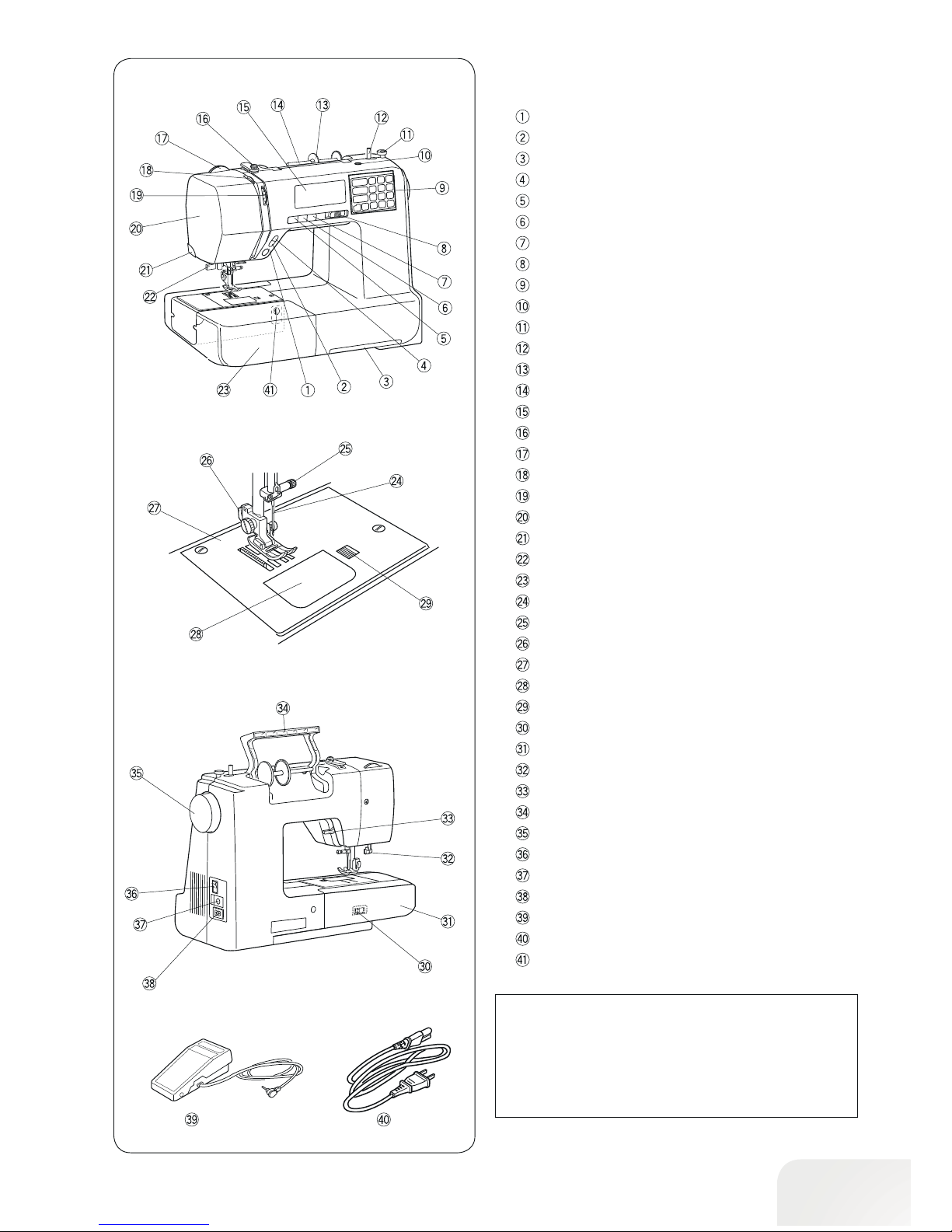
Names of Parts
Start/stop button
Reverse sewing button
Drawer for stitch overview
Auto-lock button
Needle stop up/down button
Thread cutter button
Twin Needle button
Slide speed control
Touch Panel
Hole for second spool pin
Bobbin winder stopper
Bobbin winder spindle
Spool disc large
Spool pin
LCD display
Upper thread guide
Presser foot pressure dial
Thread take-up lever
Thread tension dial
Head cover
Thread cutter
Needle Threader
Sewing table (accessory box)
Needle
Needle clamp screw
Presser foot holder
Stitch plate
Bobbin cover plate
Bobbin cover release button
Feed dog lever
Free arm
Buttonhole lever
Presser foot lever
Carrying handle
Handwheel
Power switch
Foot control connector
Power cable connection
Foot control
Power cable*
Balance
*The power cable included may differ from the illustration.
PLEASE N OTE:
To carry the sewing machine, hold the carrying handle
with your hand, and support the sewing machine with the
other hand.
Design and specifications are subject to change without
prior notice.
8
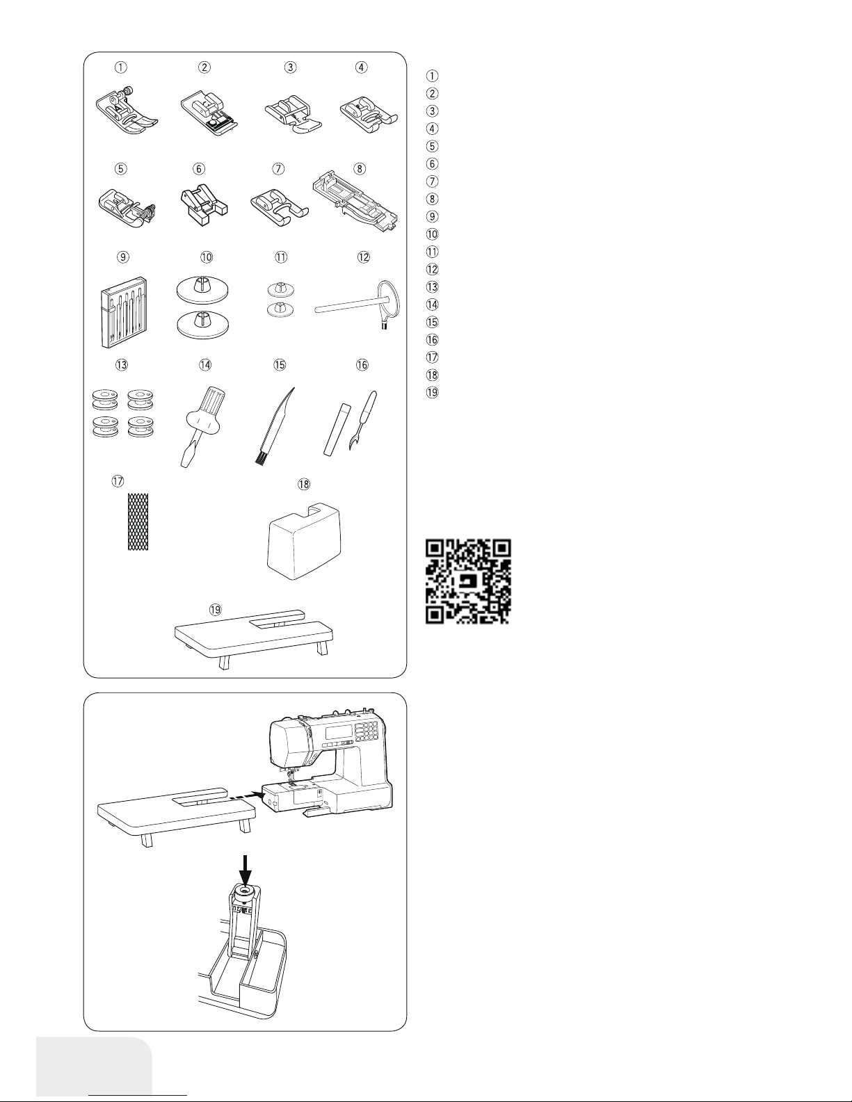
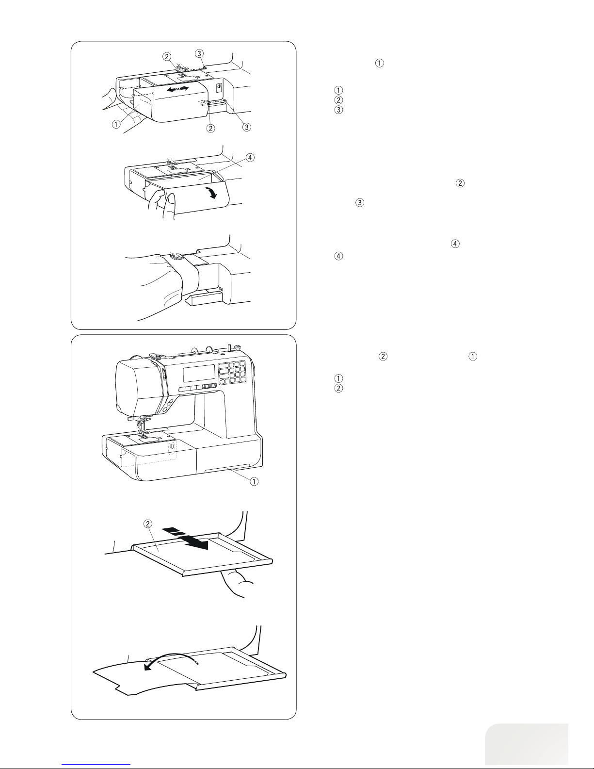
Extension table
•Attaching the table
Pull the table away from the machine.
Spread the legs of extension table.
Holding the table with both hands and slide it gently to the right.
• Adjusting the ta ble height
Turn setscrews of the table legs with a screwdriver (optional).
Standard Accessories
Zigzag foot : A (set on the machine)
Overlock foot: C
Zipper foot:E
Satin stitch foot: F
Blindstitch foot: G
Button-sew-on foot: T
Open toe foot: F2
Buttonhole foot with slide:R
Needle assortment
Spool disc (X 2) (Large)
Spool disc (X 2) (Small) (1x set on the machine)
Second spool pin
Bobbin (X 4) (1x set in the machine)
Screwdriver
Lint brush
Seam ripper (buttonhole opener)
Spool net
Hard cover
Extension table
More information on optional accessories can be found on our
website:http://www.mybernette.com/accessories
• D ust C over
Sewing instructions for your own personalized dust cover are
available at:
www.mybernette.com/cover
9
Sewing Table and Accessory box
The sewing table provides an extended sewing area and
can be easily removed for free arm sewing.
Sewing table
Pin
Hole
•Removing Sewing Table
Pull the table away from the machine, as illustrated.
• Att aching Sewing Table
Push the sewing table, inserting the pin into the hole until
the table snaps into the machine. Insert the second spool pin
into the hole
.
• Accessory box
The accessories are stored inside the sewing table. Pull the lid
towards you to open the accessory box
.
Accessory box
Free-arm sewing
Free-arm sewing is useful for darning socks and mending the
knee or cuff areas of children’s clothes.
Stitch overview
The stitch overview is stored in the drawer in the lower part
of the sewing machine.
Drawer for stitch overview
Stitch overview
Pull the drawer out with your finger as far as it will go. Turn pages
to refer the stitch overview.
10
GETTING READY TO SEW
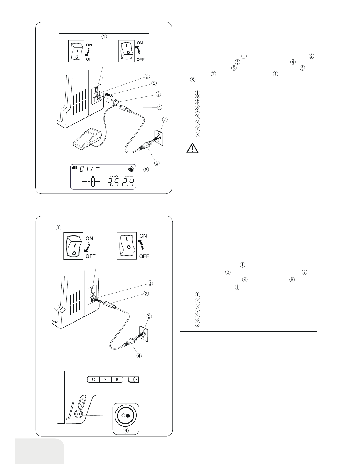
Connecting the Power Supply
•Using the foot control
Switch off the power switch . Insert the foot control plug
into the foot control jack . Insert the cable plug into the
power cable connection
. Insert the power supply plug into
the wall outlet
. Turn on the power switch . The foot control
sign
will be displayed when the foot control is connected to
the machine.
Power switch
Foot control plug
Foot control jack
Cable plug
Power cable connection
Power supply plug
Wall outlet
Foot control sign
WARNING:
While in operation, always keep your eyes on the sewing
area, and do not touch any moving parts such as the
thread take-up lever, handwheel or needle.
Always turn off the power switch and unplug from the
power supply:
- when leaving the machine unattended.
- when attaching or removing parts.
- when cleaning the machine.
Never place anything on the foot control.
Before Using Your Sewing Machine
Before using your sewing machine for the first time, place a
scrap of fabric under the presser foot and run the machine
without thread for a few minutes. Wipe away any oil which may
appear.
• Using the start/stop button
Switch off the power switch .
Insert the cable plug
into the power cable connection .
Insert the power supply plug
into the wall outlet .
Turn on the power switch
.
Power switch
Cable plug
Power cable connection
Power supply plug
Wall outlet
Start/stop button
PLEASE N OTE :
The star t/stop button does not work when the foot control
is connected.
• Op erating Instructions:
The symbol “0” on a switch indicates the “off” position of a
switch.
For appliances with a polarized plug (one blade wider than the
other): To reduce the risk of electric shock, this plug is intended
to fit in a polarized outlet only one way.
If it still does not fit, contact a qualified electrician to install the
proper outlet. Do not modify the plug in any way (U.S.A. and
Canada only).
* Foot control model YC-485EC-1 is used with this sewing
machine.
11
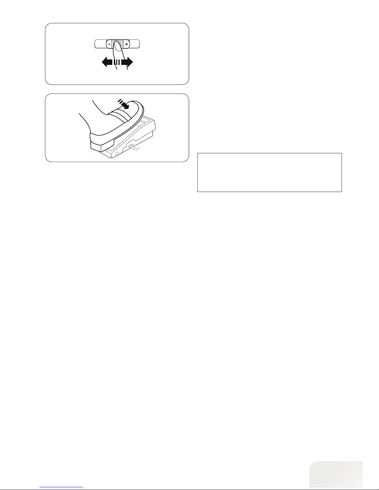
Controlling Sewing Speed
• Slide spe ed control
Sewing speed can be varied by the slide speed control according to your sewing needs.
To increase sewing speed, slide the slider to the right.
To decrease sewing speed, slide the slider to the left.
• Foot cont rol
Depress the foot control to start the machine.
The further down you press on the foot control, the faster the
machine runs.
The maximum sewing speed can be varied by the slide speed
control.
PLEASE N OTE :
The machine will not run and the presser foot mark will
blink if you start the machine with the presser foot in the
highest position. Lower the presser foot and press the
foot control.
12
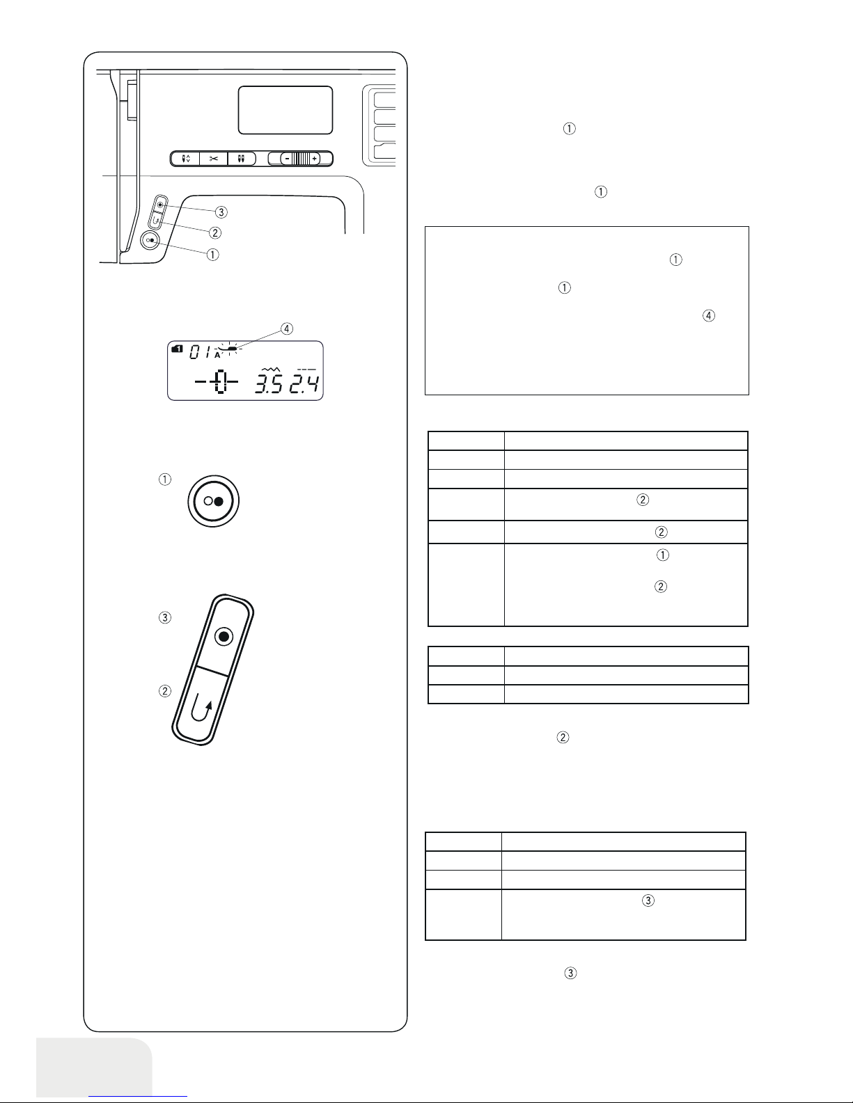
• Reverse sewing button
•Auto-lock button
•Start/stop button
Lower the presser foot lever.
Press the start/stop button
to start the machine.
The machine will sew the left row first. The machine starts running slowly for the first few stitches, and it then runs at the
speed set by the slide speed control.
Press the start/stop button again
to stop the machine.
PLEASE N OTE :
The machine runs slowly as long as this button is
being pressed.
The start/stop button
cannot be used when the foot
control is connected to the machine.
The machine will not run and the presser foot mark
will
blink if you start the machine with the presser foot in the
highest position. Lower the presser foot and press the
start/stop button.
Machine Operating Buttons
Mode 1
07
Mode 2
07, 11, 28, 29
Function
Pages 30, 46, 47
Mode 1
01, 02, 05, 06
Mode 2
01, 02, 05, 06, 13,
Mode 3
01, 59, 60
Function
Press the Auto-lock button
, to sew a locking
stitch immediately. The machine will automatically stop.
Mode 1
01, 02, 05, 06
Mode 2
01, 02, 05, 06, 13
Mode 3
01, 59, 60
Reverse
sewing
Hold the Reverse button
pressed.
Sewing
Release the Reverse button
.
Reverse
sewing
slowly
Press the start/stop button
, the machine
stops.
Hold the Reverse button
pressed, the
machine sews in reverse slowly as long the
button is pressed.
Any other st itch e s
Press the reverse button
, to sew a locking stitch immediately.
The machine will automatically stop.
The exception is by all the eyelets and buttonholes, with which the
reverse button remains without function.
•Any other stitches
Press the auto-lock button
to sew a locking stitch at the end
of current pattern.
The machine will automatically stop.
13
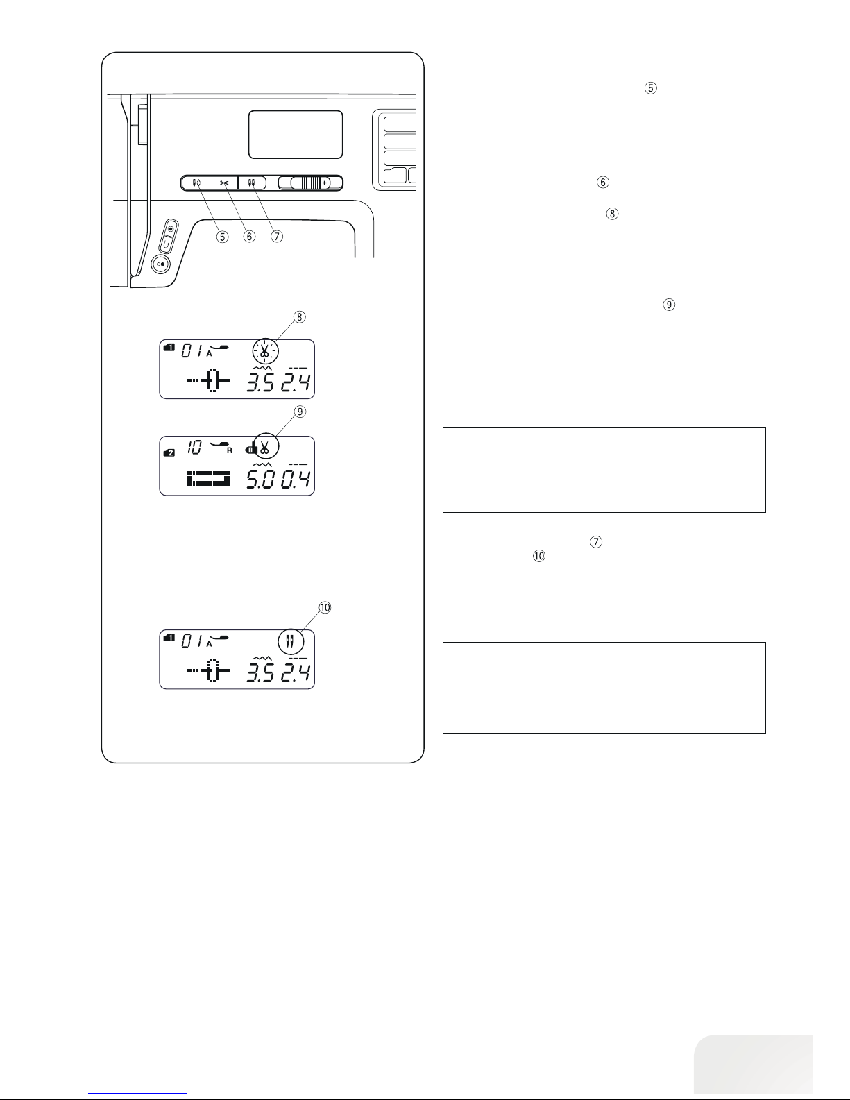
• Ne edle stop up/down button
Press the needle stop up/down Button
to bring the needle
up or down.
• Thread cutter button
Press the thread cutter button to trim the threads after sewing.
The thread cutter mark will blink
, while the machine cuts the
threads.
You can continue sewing without pulling the bobbin thread up
after trimming the threads.
To trim the threads automatically after sewing, select the
desired stitch pattern, then press and hold the thread cutter
button until the thread cutter mark appears
.
The machine will trim the threads automatically after the locking stitch then stop when the Reverse sewing stitch or autolock
button is pressed, or a pattern has the auto-lock stitch programmed.
•Twin Needle button
Press the twin needle button when using a twin needle. The
twin needle mark
will appear when it is activated.
To cancel or finish the twin needle sewing, press the twin needle button twice.
PLEASE N OTE :
When the twin needle mark is blinking, all the other keys
and buttons will not be responding. Press the twin needle
button again.
For twin needle sewing, please refer to page
54.
PLEASE N OTE :
Use the thread cutter on the head cover if the thread is
#30 or thicker.
14
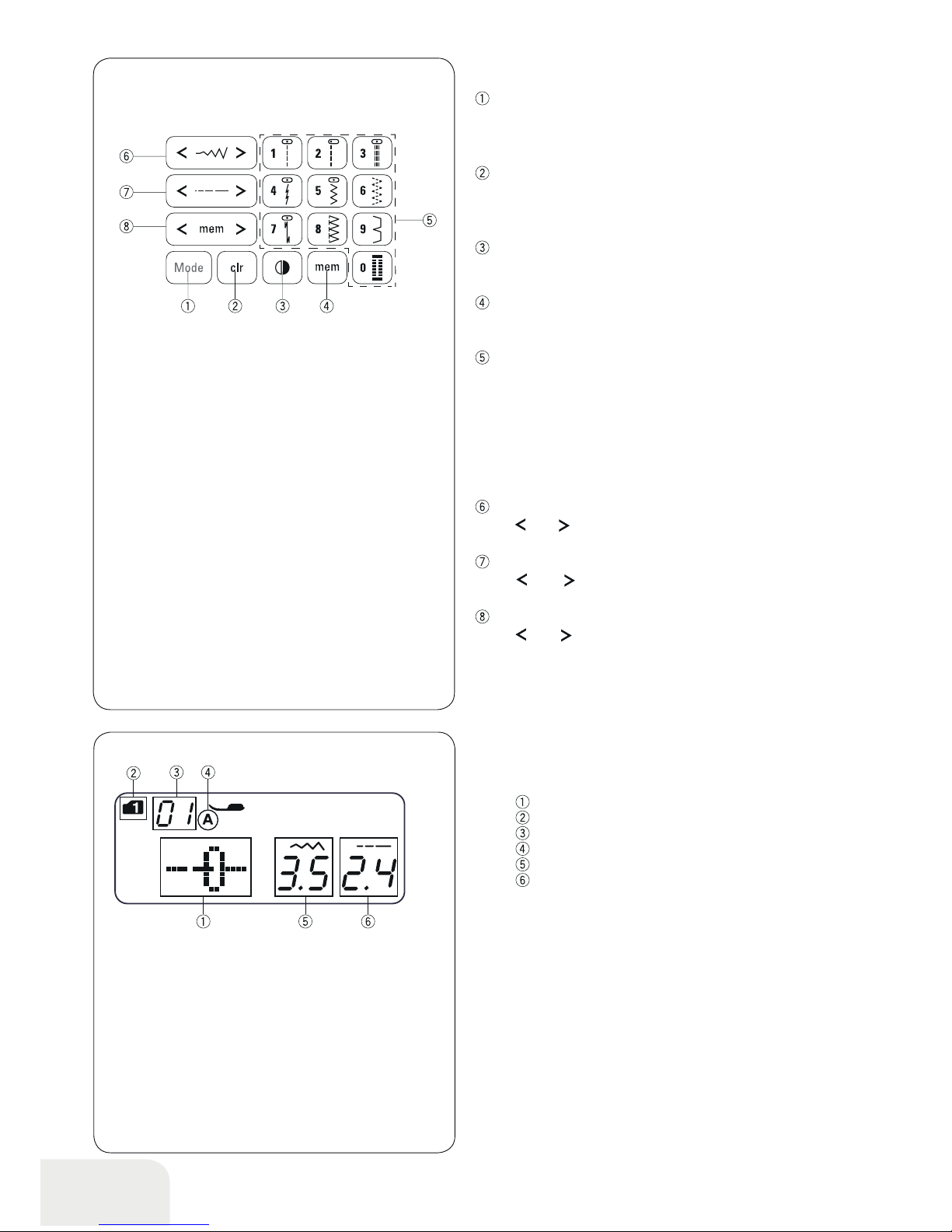
Mode button
When the power switch is turned on, the direct pattern selection
(mode 1) is set automatically.
Press the mode button to change the mode. Refer to page 24.
Clear button
Press the clear button to clear the memorized stitch pattern.
Press and hold the clear button until the buzzer beeps to clear
all memorized stitch patterns. Refer to page 62.
Mirror Image button
Press the mirror image button to flip the selected stitch pattern
horizontally. Refer to page 58.
Memory button
Press the memory button to memorize the selected pattern.
Refer to page 56.
Number bu t ton ( Refer to page 24)
• Direct pattern selection
You can select the stitch patterns from 01 to 10 directly in mode
1 (direct pattern selection mode).
• Numeric pattern selection
Enter a 2-digit pattern number to select the desired stitch pattern in mode 2 to 6.
Stitch width button
Press “
” or “ ”, to change the stitch width. Refer to page 29,
32.
Stitch length button
Press “
” or “ ”, to change the stitch length. Refer to page
29.
Cursor
Press “
” or “ ”, to move the cursor to check or edit the pat-
tern combination. Refer to page 62.
Touch Panel
LCD Display
The LCD display shows the following information when the
machine is turned on.
Stitch pattern
Mode
Stitch pattern number
Type of presser foot
Stitch width
Stitch length
15
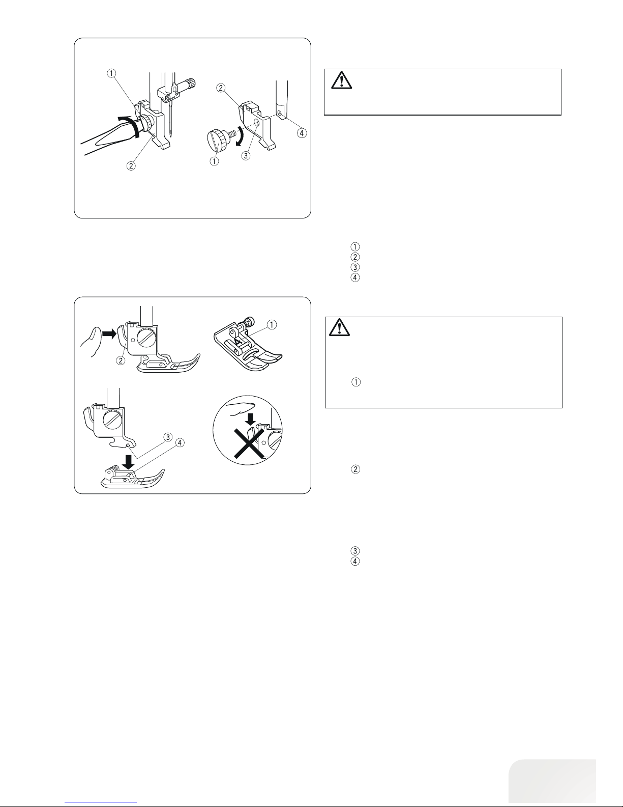
Attaching and Removing the Presser Foot
Holder
• Removing Presser foot holder
Remove the setscrew by turning it counterclockwise with
a screwdriver.
• Attaching Presser foot holder
Match the hole in the presser foot holder with the
threaded hole in the presser bar.
Fit the setscrew into the hole.
Tighten the setscrew by turning it clockwise with the
screwdriver.
Setscrew
Presser foot holder
Hole
Threaded hole
CAUTION:
Turn OFF the power switch before removing or attaching
the presser foot holder.
Changing the Presser Foot
• Removing the presser foot
Raise the needle to its highest position by turning the handwheel counterclockwise. Raise the presser foot, and press the
lever on the back of the presser foot holder.
Lever
• Attaching the presser foot
Place the desired presser foot, so that the pin on the foot lies
just under the notch on the presser foot holder.
Lower the presser foot lever to lock the foot in place.
Notch
Pin
CAUTION:
Turn OFF the power switch before changing the foot.
Always use the proper foot for the selected pattern.
The wrong foot can cause the needle to break. Each foot
is marked with an identification letter.
Identification letter
16
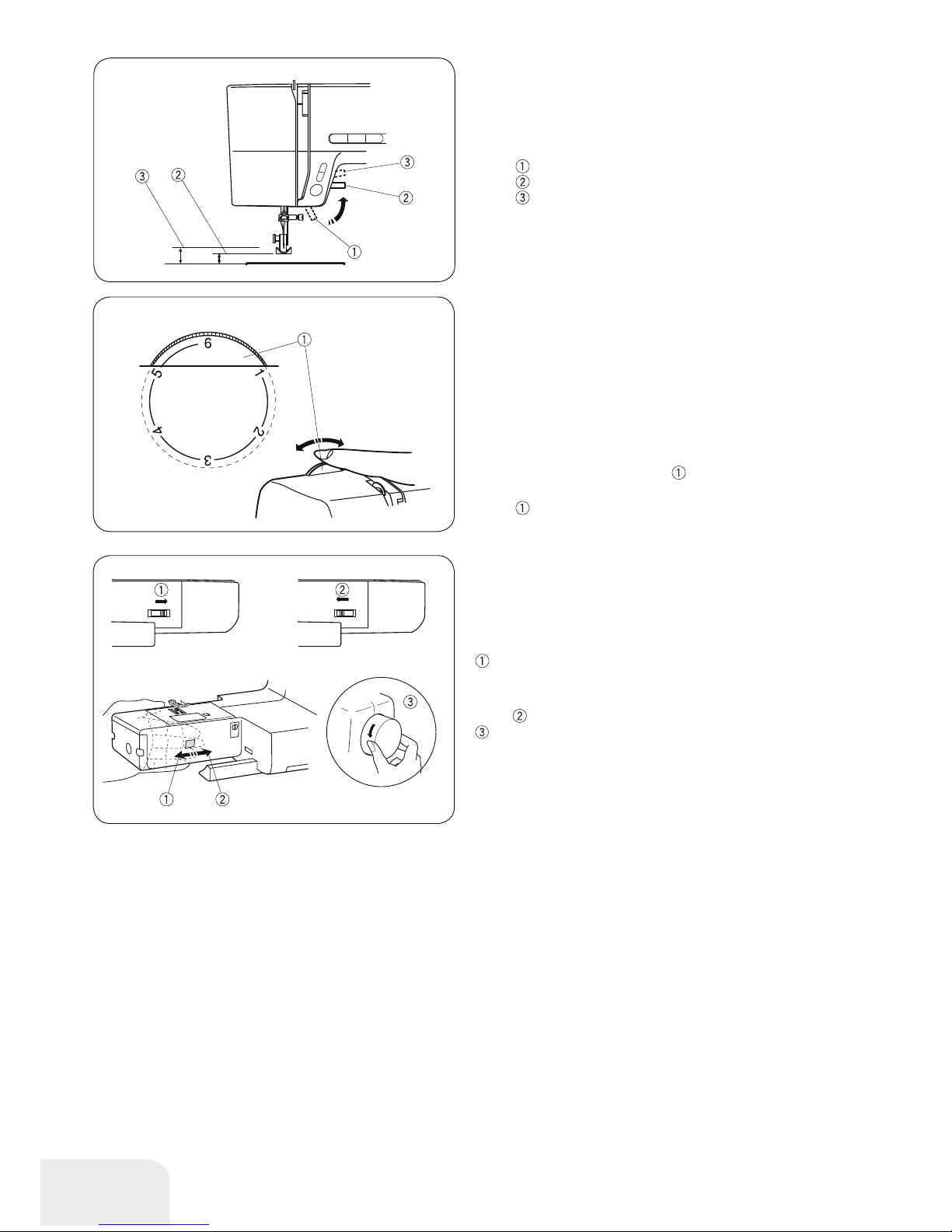
Presser Foot Lever
The presser foot lever raises and lowers the presser foot.
You can raise the foot about 1/4˝ (0.6 cm) higher than the normal up position for easy removal of the presser foot, or to help
you place thick material under the foot.
Presser foot lever
Normal up position
Highest position
Presser Foot Pressure Dial
The presser foot pressure dial should be set at “6” for regular
sewing.
Set the pressure between “3” and “6” for appliqué, cutwork,
drawn work, basting and embroidery.
Set the pressure between “1” and “3” when sewing chiffon, lace,
organdy and other fine fabrics.
Velour and knits with a lot of stretch may also require a “1” setting.
Turn the presser foot pressure dial
and set the desired num-
ber.
Presser foot pressure dial
Dropping or Raising the Feed Dog
The drop feed dog lever is located underneath the free arm bed
on the back of the machine.
To drop the feed dog, push the lever in the direction of the arrow
.
To raise the feed dog, push the lever in the direction of the
arrow
, as illustrated, and turn the handwheel toward you
.
The feed dog must be up for normal sewing.
17
Fabric Thread Needle
Fine
Lawn
Georgette
Tricot
Organza
Crepe
Silk #80-100
Cotton #80-100
Synthetic #80-100
#9/65-11/75
Needle with
blue shank
Medium
Sheeting
Jersey
Broadcloth
Fleece
Silk #50
Cotton #50-80
Synthetic #50-80
#11/75-14/90
Heavy
weight
Denim
Tweed
Coating
Quilting
Silk #30-50
Cotton #40-50
Synthetic #40-50
#14/90-16/100
Fabric and Needle Chart
• Use a needle size of 11/75 or 14/90 for general sewing
work.
• A fine thread and needle should be used for sewing light-
weight fabrics, so the fabric will not be marred.
• Heavy fabric requires a needle large enough to pierce the
fabric without the needle thread fraying.
• Always test the needle size on a small scrap of the fabric
that will be used for actual sewing.
• In general, use the same thread for the needle and bobbin.
• Use a blue shank needle when sewing flexible fabrics,
very fine fabrics and synthetic fabrics. The blue shank
needle effectively prevents skipped stitches.
PLEASE N OTE :
1 x Twin Needle, 1 x Needle with blue shank (No. 11/75),
2 x Needle No. 11/75 and 1 x Needle No. 14/90 are in the Needle assortment included.
For optimal sewing results, we recommend using Organ needles.
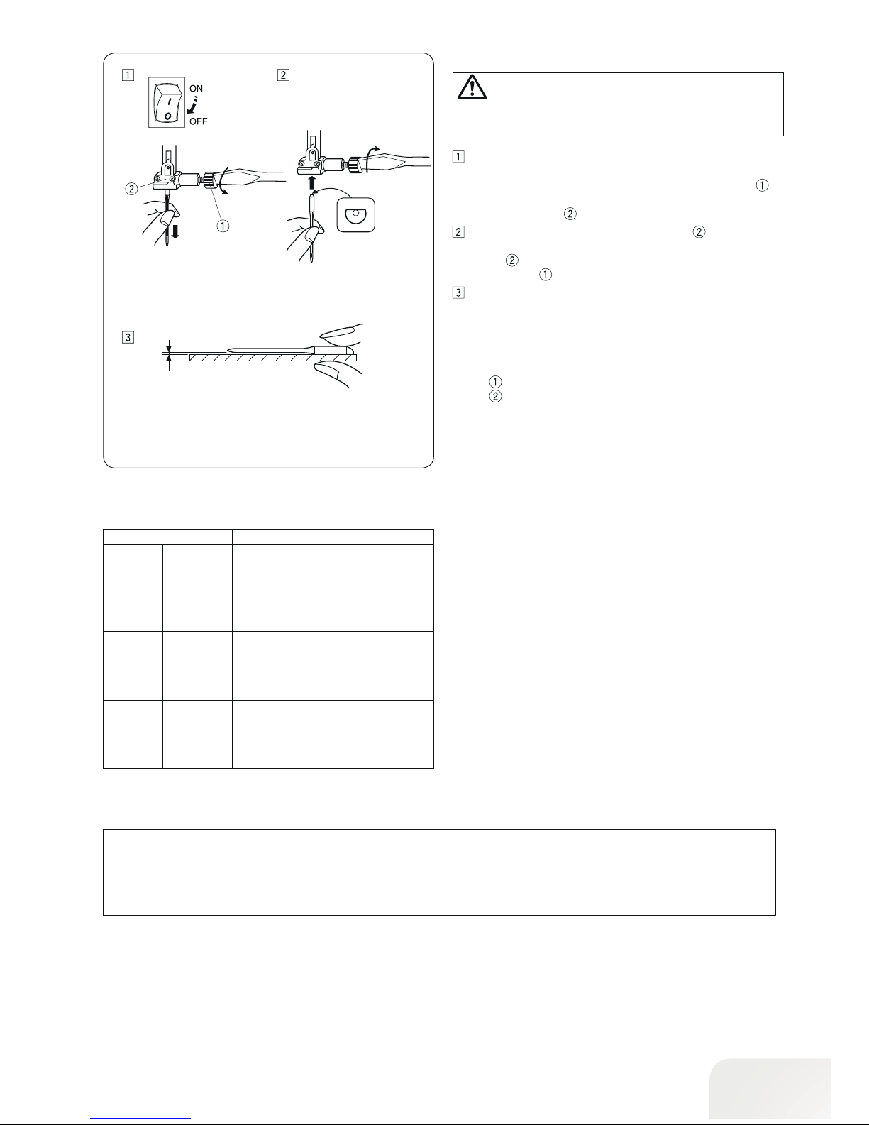
Changing the Needle
Switch off the power switch. Raise the needle to its highest
position by turning the handwheel counterclockwise and
lower the presser foot. Loosen the needle clamp screw
by turning it counterclockwise. Remove the needle from
the needle clamp
.
Insert a new needle into the needle clamp with the flat
side to the rear. When inserting the needle into the needle
clamp
, push it up as far as it goes. Tighten the needle
clamp screw
firmly by turning it clockwise.
To see if the needle is good, place the flat side of the
needle onto something flat (stitch plate, glass, etc.).
The gap between the needle and the flat surface should
be consistent. Never use a bent or blunt needle. A damaged needle can cause permanent snags or runs in knits,
fine silks and silk-like fabrics.
Needle clamp screw
Needle clamp
CAUTION:
Turn OFF the power switch before changing the needle.
18
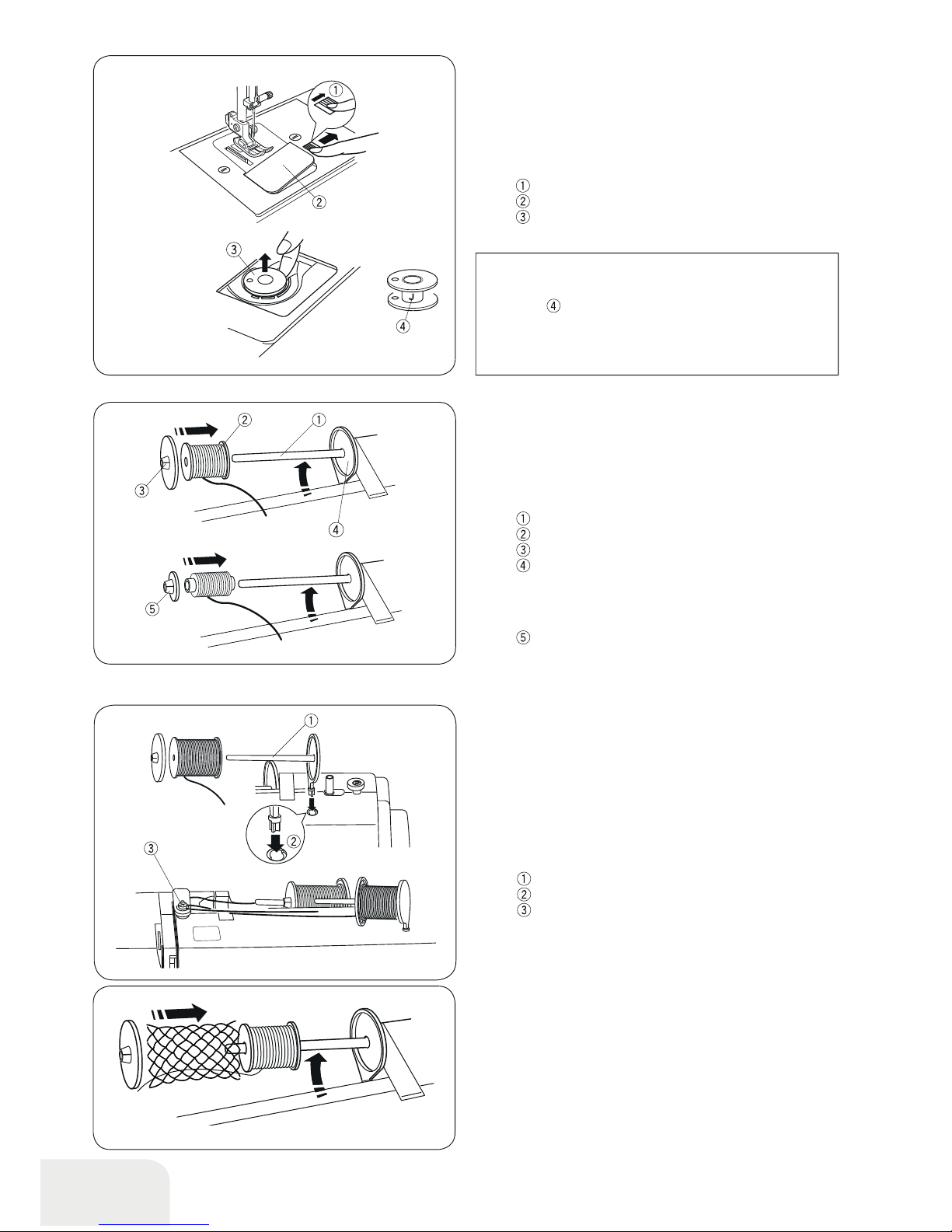
Second spool pin
The second spool pin is for winding bobbins without unthreading the machine.
Insert the second spool pin into the hole.
The second spool pin should point to the bobbin winder tension
disc.
Draw the thread from the spool and pass the thread around the
bobbin winding tension disc as shown.
Second spool pin
Hole for second spool pin
Bobbin winder tension disc
Bobbin Winding and Inserting
• Removing the bobbin
Gently slide the hook cover release button to the right and
remove the hook cover plate.
Lift out the bobbin.
Hook cover release button
Hook cover plate
Bobbin
PLEASE N OTE :
Use the “J” plastic bobbins for horizontal hook (marked
with “J”
). Using other bobbins, such as pre-wound
paper bobbins, may cause stitching problems and/ or
damage to the bobbin holder.
• Set ting the Spool of Thread
Horizontal spool pin
Lift up the spool pin. Place a spool of thread on the spool pin.
Attach the large spool disc, and press it firmly against the spool
of thread so that the spool rests on the supporter.
Spool pin
Spool
Large spool disc
Supporter
The small spool disc is used with narrow or small spools of
thread.
Small spool disc
•Spool net
Polyester or bulky nylon threads become loose while unwinding.
To keep consistent feeding of such threads, pull the spool net
over the spool.
19
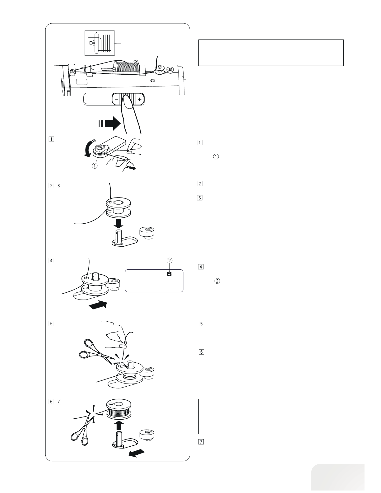
•Bobbin Winding
PLEASE N OTE :
Set the slide speed control at its fastest position for bobbin winding.
Draw the thread from the spool and pass the thread around
the bobbin winding tension disc.
Bobbin winder tension disc
Thread through the hole in the bobbin from the inside to the
outside.
Put the bobbin on the bobbin winder spindle.
Push the bobbin to the right.
The bobbin icon appears on the LCD display.
Bobbin icon
With the free end of the thread held in your hand, start the
machine. Stop the machine when it has wound a few layers,
and then cut the thread close to the hole in the bobbin.
Start the machine. When the bobbin is fully wound, it will
stop automatically. Stop the machine and return the slide
speed control position. Shift the bobbin winder spindle to
the left for stitching. Cut the thread as shown.
PLEASE N OTE :
For safety purposes, the machine will automatically
stop 1.5 minutes after starting bobbin winding.
Remove the bobbin. Cut the thread as shown.
Return the slide speed control position.

20
• Inser t the bobbin
Put one bobbin on the bobbin winder spindle. Place a bobbin in the bobbin holder with the thread running off counterclockwise.
End of thread
Guide the thread into the first notch on the front side of
the bobbin holder.
Notch
Draw the thread to the left, sliding it between the tension
spring blades.
Continue to draw the thread lightly until the thread slips
into the second notch
. Pull out about 6˝ (15 cm) of
thread.
Notch
Attach the hook cover plate. Check the threading. Refer to
the diagram
shown on the hook cover plate.
Threading diagramm
21
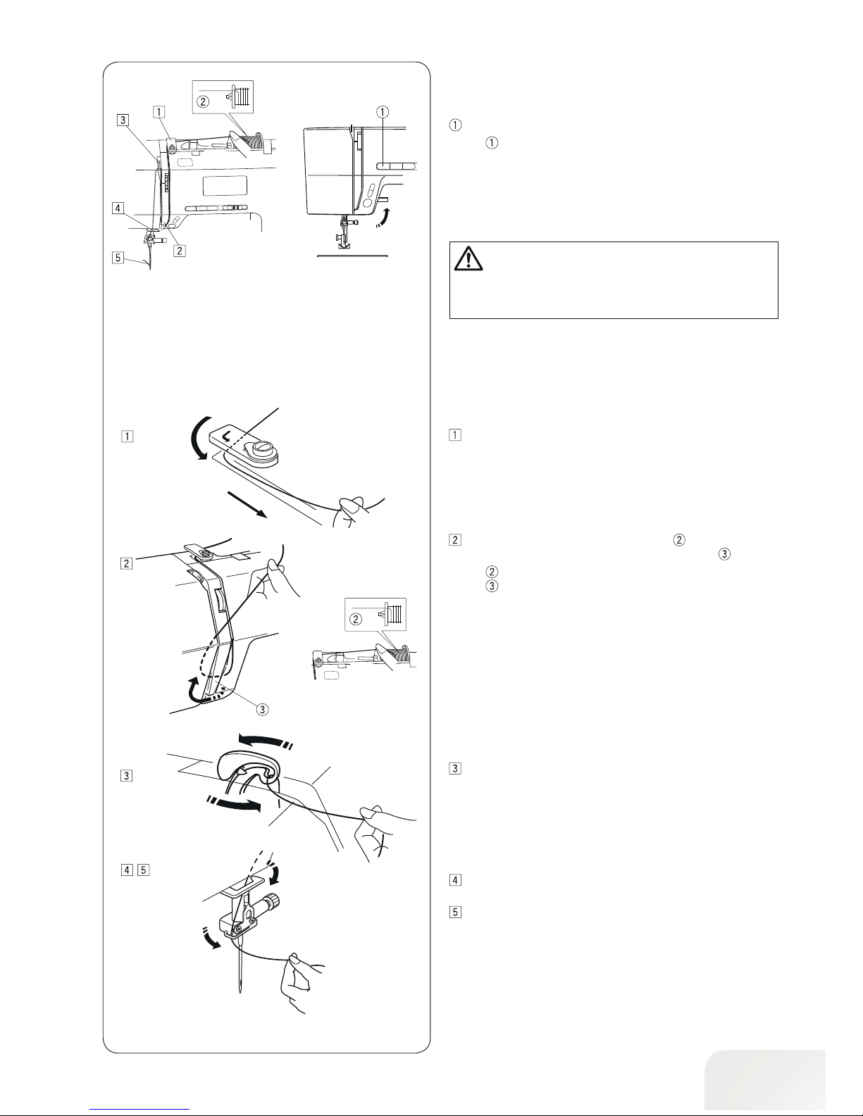
Draw the end of the thread around the upper thread guide.
Threading the Machine
• Threading the Machine
CAUTION:
Turn OFF the power switch before threading the machine.
While holding the thread near the spool , draw the end of
the thread down around the check spring holder
.
Spool
Check spring holder
Firmly draw the thread up from right to left over the takeup lever, and down into the take-up lever eye.
Pass the thread through the lower thread guide. Slide the
thread behind the needle bar thread guide on the left.
Thread the needle from front to back, or use the needle
threader.
Raise the presser foot. Press the needle stop up/down button
to raise the thread take-up lever to its highest position.
Needle stop up/down button
22
PLEASE N OTE :
The needle threader can be used with a #11 to #16 needle or a blue shank needle. Thread sizes 50 to 90 are
recommended.
The threader can't be used for a twin needle.
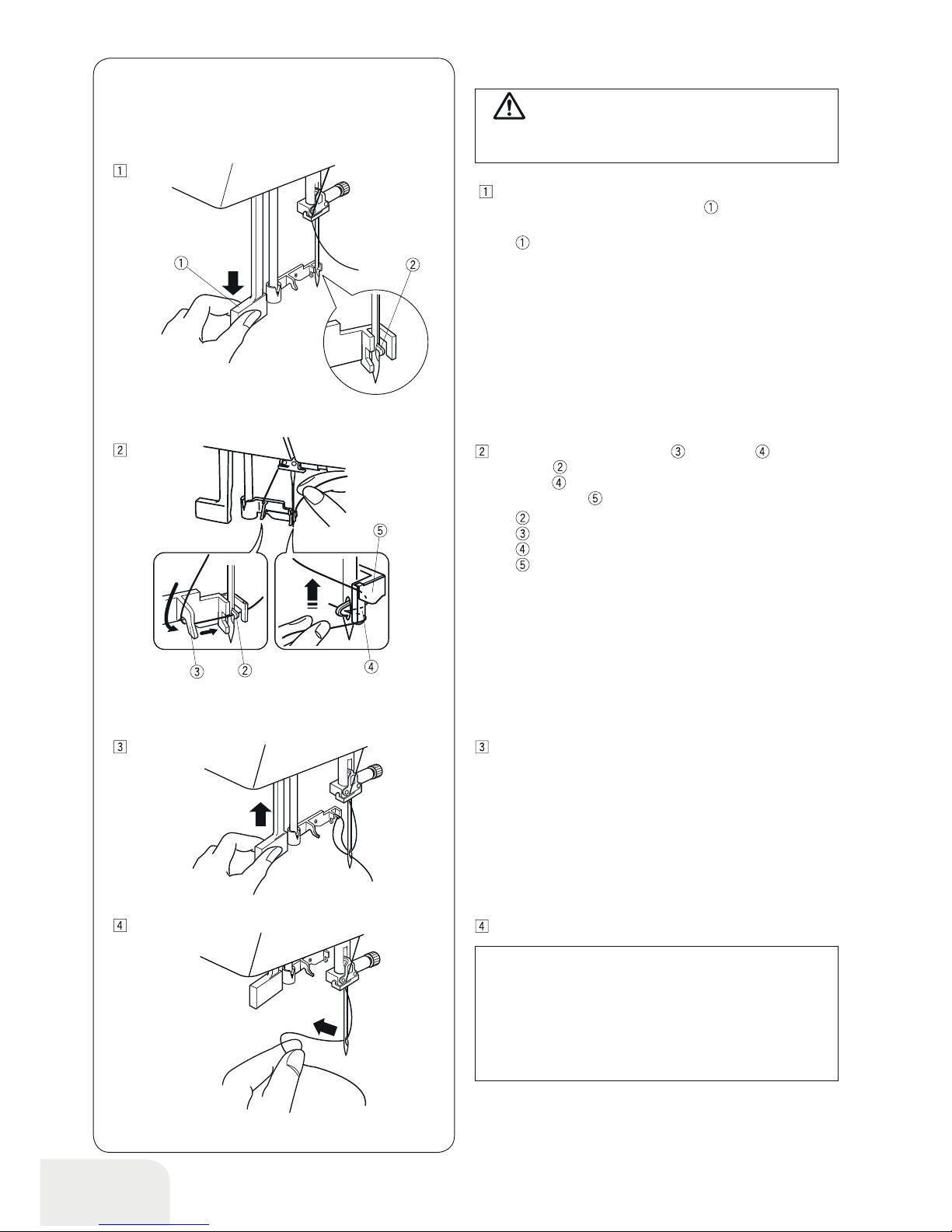
•Needle threader
Draw the thread from guide (a) to guide (b) and under
the hook
. Draw the thread up along the right side of
guide (b)
and slip the thread in between guide (b) and
the holder plate
.
Hook
Guide (a)
Guide (b)
Holder plate
Raise knob threader in the direction of the arrow, drawing
the thread loop through the needle.
Pull the thread through the needle eye.
CAUTION:
Turn OFF the power switch when using the needle
threader.
Lower the presser foot. Raise the needle to its highest position. Pull down the needle threader
as far as it will go.
The hook comes out through the needle eye from behind.
Knob
 Loading...