

Page 1
IMPORTANT INSTRUCTIONS
Saving energy and creating healthy, comfortable environments
READ AND SAVE
THESE INSTRUCTIONS
No. II-230
Date May, 2014
INDUSTRIAL
Direct Drive 12 & 14
AIR CURTAIN SERIES IDC12 / IDC14
for outdoor use
unheated only
FDA
RECOMMENDED
USDA
COMPLIANCE
Installation & Maintenance Instructions
TABLE OF CONTENTS
I. UNCRATING......................................................................................................................................................................................................... 2
II. MOUNTING INSTRUCTIONS ............................................................................................................................................................................ 2
III. WALL MOUNTING ............................................................................................................................................................................................ 3
IV. SUSPENDED MOUNTING ............................................................................................................................................................................... 4
V. VERTICAL MOUNTING ..................................................................................................................................................................................... 4
VI. TANDEM MOUNTING BRACKETS (for Vertical Mounting)....................................................................................................................... . 4
VII. ELECTRICAL CONNECTIONS ....................................................................................................................................................................... . 4
VIII. MECHANICAL CONNECTIONS ................................................................................................................................................................... . 5
IX. OPERATION INSTRUCTIONS ........................................................................................................................................................................ . 6
X. MAINTENANCE AND CLEANING .................................................................................................................................................................... 6
XI. SERVICE ............................................................................................................................................................................................................ 6
XII. WARRANTY .................................................................................................................................................................................................... . 8
WARNING: TO REDUCE THE RISK OF FIRE, ELECTRIC SHOCK OR INJURY TO PERSONS, OBSERVE THE FOLLOWING:
A. Read all instructions before installing or using this air curtain.
B. Use this unit only in the manner intended by the manufacturer and described in this manual. Any other use not recommended by the
manufacturer may cause re, electric shock, or injury to persons. If you have any questions, contact the manufacturer.
C. Before servicing or cleaning unit, switch power o at service panel and lock the service disconnecting means to prevent power from
being switched on accidentally. When the service disconnecting means cannot be locked, securely fasten a prominent warning device,
such as a tag, to the service panel.
D. Installation work and electrical wiring must be done by qualied person(s) in accordance with all applicable national and local codes
having jurisdiction, including re-rated construction. See page 4, ELECTRICAL CONNECTIONS (NEC Code ANSI/NFPA No. 70).
E. When cutting or drilling into wall or ceiling, do not damage electrical wiring and other hidden utilities.
F. To reduce the risk of re, do not store or use gasoline or other ammable vapors and liquids in the vicinity of the air curtain.
G. This air curtain is hot when in use. To avoid burns, do not let bare skin touch hot surfaces. Keep combustible materials, such as furniture,
pillows, bedding, papers, clothes, etc. and curtains at least 1 inch from the top, back, front, sides and at least 6 feet from the discharge of
the air curtain.
H. Extreme caution is necessary when any air curtain is used by or near children or invalids, and whenever the heater is left operating
unattended.
I. Do not operate any air curtain after it malfunctions. Disconnect power at the service panel and have the air curtain inspected by a
reputable electrician before reusing.
J. To disconnect the air curtain, turn controls to “o”, and turn o power to the air curtain circuit at main disconnect panel.
K. Do not insert or allow foreign objects to enter any ventilation or discharge opening as this may cause an electric shock or re, or damage
the air curtain.
L. To prevent a possible re, do not block the air intake or discharge of the air curtain in any manner.
M. The air curtain has hot and arcing or sparking parts inside. Do not use it in areas where gasoline, paint, or ammable vapors or liquids are
used or stored.
N. This heater may include an audible or visual alarm to warn that parts of the heater are getting excessively hot. If the alarm sounds (or
illuminates), immediately turn the heater o and inspect for any objects on or adjacent to the heater that may have blocked the airow or
otherwise caused high temperatures to have occurred. DO NOT OPERATE THE HEATER WITH THE ALARM SOUNDING (OR ILLUMINATING).
Page 2

I. UNCRATING
Carefully examine the carton(s) for damage before opening. If
the carton is damaged, immediately notify shipping company.
If the unit(s) were shipped on wooden skids, remove protective
wood and banding straps securing the carton(s) to the skid.
Open the carton(s) and remove all protective packaging. Immediately verify that the electrical rating nameplate located on
the cover matches the electrical power supply available. Retain
the shipping carton(s) until the unit(s) is installed and properly
operating.
ACCESSORIES: If the unit(s) were ordered with optional electrical accessories (door switch, control panel, etc.), the accessories
may be found in the carton containing the unit or in a separate
carton(s) accompanying the unit(s). Check all of the cartons/
skids for accessories before discarding.
mounting method and; as a general rule, use the mounting
conguration that positions the air door as close to the top
of the doorway as possible without interfering with door
operation.
B. The IDC12/IDC14 Series air door is designed to be an
eective barrier against cold drafts in the winter and hot
air in the summer. To achieve optimum protection, the
unit should be mounted on the inside of the building, ush
to the wall and as close to the top of the door opening as
possible. To ensure peak performance keep the air stream
free of obstructions. If the air door cannot be installed ush
with the wall, be sure to seal the gap between the wall and
the back of the air door along the entire length of the unit to
prevent airow through this void.
II. MOUNTING INSTRUCTIONS
(General Notes for All Mounting Congurations)
INDOOR MOUNTING - Environmental/Insect/Dust Control
OUTDOOR MOUNTING (Unheated Only) - Insect/Dust Control
A. Berner IDC12/IDC14 air doors are designed to be mounted
by their end anges without the need for intermediate
support. Each end ange contains (8) total ½” holes located
on all (4) sides to facilitate mounting exibility and the easy
addition of mounting accessories. Units may be attached to
the wall directly, suspended from overhead, or supported
by brackets. The style of door will determine the best
Weight by Unit Type
Model
Ambient
IDC12-1036 90 96 130 130 125
IDC12-1042 101 107 145 145 125
IDC12-1048 109 115 158 158 125
IDC12-1060 119 125 178 178 125
IDC12-2060 160 172 219 219 130
IDC12-2072 167 179 229 229 130
IDC12-2078 178 190 244 244 130
IDC12-2084 188 200 258 258 130
IDC12-2096 203 215 282 282 130
IDC12-3096 233 251 312 312 145
IDC12-2108 212 224 296 296 130
IDC12-3108 251 269 335 335 145
IDC12-2120 221 233 311 311 130
IDC12-3120 272 290 362 362 145
IDC12-3132 289 307 390 390 145
IDC12-3144 304 322 412 412 145
IDC12-4144 335 359 443 443 225
IDC12-4156 355 379 471 471 2 @ 130
IDC12-4168 376 400 499 499 2 @ 130
IDC12-4180 391 415 523 523 2 @ 130
IDC12-5180 419 449 551 551 2 @ 145
IDC12-4192 405 429 544 544 2 @ 130
IDC12-5192 435 465 574 574 2 @ 145
* Weight includes heater and duct transition
Electric
Heat
Steam
Heat
Hot
Water
Heat
TABLE 1
Indirect
Gas
Heat*
C. The air door will not perform properly if negative air
pressure exists in the building. Under these conditions,
a means for makeup air to the building must be provided
so that the air pressure on both sides of the opening is in
balance.
D. Before mounting the air door, check the supporting
structure to verify that it has sucient load-carrying capacity
to support the weight of the unit(s). The mounting hardware
(supplied by others) should be capable of supporting a
minimum of three (3) times the weight of the unit. See
Tables 1 & 2.
Weight by Unit Type
Model
IDC14-1036 93 99 133 133 125
IDC14-1042 104 110 148 148 125
IDC14-1048 112 118 161 161 125
IDC14-1060 122 128 181 181 125
IDC14-2060 163 175 222 222 145
IDC14-2072 170 182 232 232 145
IDC14-2078 181 193 247 247 145
IDC14-2084 191 203 261 261 145
IDC14-2096 206 218 285 285 145
IDC14-3096 236 254 315 315 270
IDC14-2108 215 227 299 299 145
IDC14-3108 254 272 338 338 270
IDC14-2120 224 236 314 314 145
IDC14-3120 275 293 365 365 270
IDC14-3132 292 310 393 393 285
IDC14-3144 307 325 415 415 285
IDC14-4144 338 362 446 446 285
IDC14-4156 358 382 504 504 2 @ 145
IDC14-4168 379 403 534 534 2 @ 145
IDC14-4180 394 418 561 561 2 @ 145
IDC14-5180 422 452 589 589 2 @ 225
IDC14-4192 408 432 584 584 2 @ 145
IDC14-5192 438 468 614 614 2 @ 225
* Weight includes heater and duct transition
Ambient
Electric
Heat
Steam
Heat
Hot Water
Heat
TABLE 2
-2-
Indirect
Gas
Heat*
Page 3
E. The air door is weatherproof. Therefore, no special covering
is required when outdoor mounting unheated, steam, or hot
water units.
NOTE: Electric heated units are to be installed indoors
only.
F. IMPORTANT: A minimum of 4” (8” preferred) clearance
is recommended above the top of the air door for the
installation and removal of the screen or to gain access to
junction boxes.
G. When determining the mounting location for the unit(s),
make sure that nothing interferes with the curtain of air
developed when the discharge vanes are directed from 0º
to 20º toward the door opening. If the air stream strikes any
obstruction (the top edge of the doorway, a door opening
device, etc.), the eectiveness of the unit will be greatly
reduced. See Drawing 1.
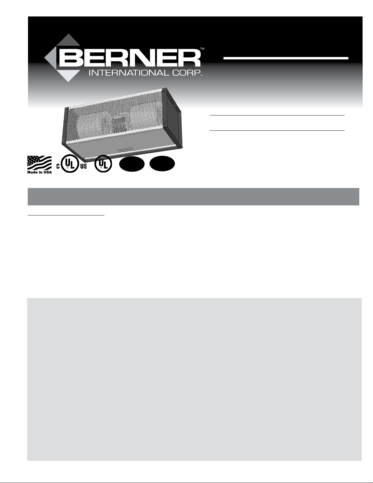
H. For optimum performance, the bottom of the unit
(discharge nozzle) should be no more than 1” above the top
of the door opening with the unit mounted ush to the wall.
If the unit must be mounted higher, it must be spaced out
from the wall ³/₈” for every inch the unit is above the door
opening. See Drawing 2.
I. Electric heated units shall:
1. Have a minimum clearance of at least 1” between the
sides and top of the unit and any combustible material.
2. Have a minimum clearance of at least 6’ between the
bottom of the unit and the oor.
3. Be installed indoors only.
DRAWING 2
III. WALL MOUNTING
A. Wall mounting works well with standard hinged doors or
sliding doors.
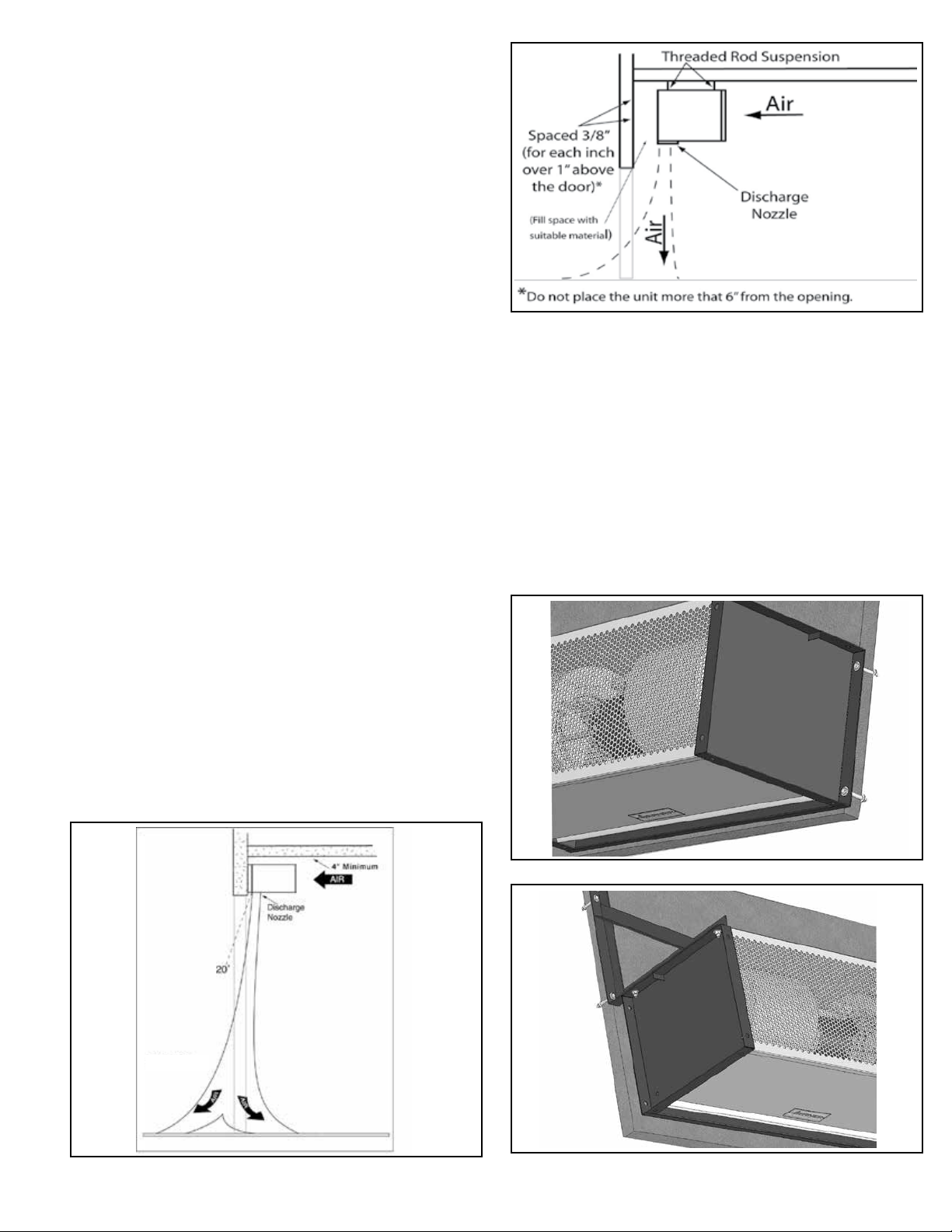
B. The IDC12/IDC14 Series end plates are equipped with ½”
holes for wall mounting. The unit may be attached to the wall
using, at minimum, ³/” bolts through the holes on the back
of the end plate. See Figure 1. Or, the unit may be attached
using an optional wall mounting bracket or a combination
of extension and wall mounting brackets (available from
Berner) attached to the holes on the top of the end plate
and the wall. See Figure 2.
C. Electrical Connections - Proceed to Section VII.
J. Proceed to one of the following sections, depending
on application and door type:
Section III: Wall Mounting
Section IV: Suspended Mounting
Section V: Vertical Mounting
Section VI: Tandem Mounting Brackets for Vertical Mounting
EXTERIOR INTERIOR
FIGURE 1 - Wall Mounting
DRAWING 1
FIGURE 2 - Wall Mounting Bracket
-3-
Page 4

FIGURE 3 - Threaded Rod Suspension
FIGURE 4 - With Extension Brackets
IV. SUSPENDED MOUNTING
A. Suspended mounting works well with the majority of door
types commonly found in an industrial setting, such as roll-
up doors, “high rise” track doors, “low-rise” turn back doors,
and “high-rise” turn back doors.
B. The IDC12/IDC14 Series end plates are equipped with ½”
holes for suspended mounting. The unit may be suspended
using a minimum ³/” suspension rod (Figure 3), or using
/” suspension rods and extension brackets (available from
³
Berner). See Figure 4.
C. Electrical Connections - Proceed to Section VII.
V. VERTICAL MOUNTING
A. Vertical mounting works well when the opening is taller
than it is wide, or when the door type prevents a typical
“over-door” mounting position.
B. Optional Floor Mounting Brackets (available from Berner)
bolt to the unit end plate, and provide a rigid base to attach
the unit to the oor. Two Brackets are required.
C. To vertically mount a IDC12/IDC14 Series unit using optional
Floor Mounting Brackets, bolt brackets on the inside of the
end plate with (4) ½ - 13 bolts as shown in Figure 5.
B. Tandem Mounting Brackets connect the end plates of the
units to be joined. Two brackets are required. Ideally, the
units are joined together before the lower unit is bolted to
the oor.
C. Using (4) ½ - 13 x 1” bolts, attach the Tandem Mounting
Brackets to the inside of one of the unit’s end plates as
shown in Figure 8.
D. Slide the end plate of the next unit over the brackets
installed in Step C and attach using (4) additional ½” bolts as
shown in Figure 9.
E. Assemble Floor Mounting Brackets to lower unit and attach
to oor per steps C and D of Section V.
F. Electrical Connections - Proceed to Section VII.
VII. ELECTRICAL CONNECTIONS
All electrical wiring and connections MUST be performed
by qualied personnel in accordance with the National
Electrical Code ANSI/NFPA No. 70 (latest edition) or, in Canada,
the Canadian Electrical Code, Part 1-C.S.A. Standard C22.1, and
local codes and regulations.
D. Position the unit vertically in its intended position and
anchor it to the oor with a minimum ³/” fastener.
See Figure 6.
E. To improve the stability of the installation, it is required
that the top of the unit be attached to the wall. A common
approach is to attach a minimum length of ³/” threaded rod
through one of the open mounting holes in the top end
plate and ax the other end of the rod to the wall.
See Figure 7.
F. Electrical Connections - Proceed to Section VII.
VI. TANDEM MOUNTING BRACKETS
(For Vertical Mount Installation)
A. Optional Tandem Mounting Brackets (available from Berner)
are used to join two air curtains together in a vertical
application when the door height exceeds 16’.
-4-
FIGURE 5 - Floor Mounting Brackets
Page 5

FIGURE 6 - Floor Mounting
FIGURE 9 - Tandem Mounting
A. Check the rating nameplate on the top of the unit for supply
voltage and current requirements. A separate line voltage
supply with a suitable branch circuit protection device
should be run directly from the main electrical panel to the
unit. A disconnect switch for each branch circuit is a required
part of this installation.
B. All eld wiring must be copper with a minimum insulation
of 60° C within approved conduit. If any of the wire supplied
with the unit must be replaced, it must be replaced with
copper wiring with a minimum insulation of 90° C.
C. Remove the Junction Box cover.
D. Connect the power supply to the unit. Connect all supply
and control circuit wires according to wiring diagram
provided.
E. Re-install the Junction Box cover.
NOTE: For electric heated units provided with optional
remote thermostat: Mount and wire the thermostat
according to instructions and wiring diagram.
VIII. MECHANICAL CONNECTIONS
A. ELECTRIC HEATED MODELS
The heater circuit may be controlled by a remote thermostat
or manually through the switch located on the discharge
side of the unit. Overheating protection is provided by auto
reset thermal cutouts built into the heater coil assembly (see
the wiring diagram).
B. STEAM OR HOT WATER HEATED MODELS
Piping should be done in accordance with local codes,
regulations and standard practices. Connect the building
system supply and return to the MNPT nipples on the
heating coil. See Figure 10.
FIGURE 7 - Increased Stability for Vertical Mounting
FIGURE 8 - Tandem Mounting for Vertical Mounting
FIGURE 10 - Mechanical Connection - Steam/Hot Water
-5-
Page 6

IX. OPERATING INSTRUCTIONS
A. GENERAL OPERATION
Air curtain operation may be divided into four areas:
control package, fan activation, fan speed selection,
and heat activation. The air curtain must be properly
installed before it is used.
1. Control packages control the unit’s sequence of operation.
Unit modes/control packages are built into the unit and may
not be changed in the eld.. Refer to your wiring diagram
for specics about activation connections and sequence of
operation.
a. Basic Control Package – The unit is activated by a door
switch. The door switch may be line voltage or low
voltage (24V).
b. Deluxe Control Package – The unit is activated by a door
switch, but has a factory installed time delay allowing
the unit to keep running for a period of time after the
door closes.
c. Comfort Plus Control Package – Available only on heated
units, the unit is activated by the door switch OR by the
thermostat to provide supplemental heating.
2. Unheated units will have the fans activated by a door switch
or sensor. The unit may be single speed and require no fan
speed selector (On/O ), or may have multiple fan speeds
which require either a unit or remote mounted switch
(O, High, Med, Low).
3. Heated units will have fans activated by a door switch or
sensor, but may also be activated by the thermostat in
Comfort Plus Mode. The unit may be single speed and
controlled by either a unit or remote mounted switch (Fan,
O, Heat), or may have multiple fan speeds which can be set
by either a unit or remote mounted switch (Low, Med, High,
O, Low heat, Med Heat, High Heat).
4. Heat activation is controlled by either a unit or remote
mounted thermostat, and a unit or remote mounted switch.
B. AIR STREAM ADJUSTMENT
1. With the air curtain operating and the door in its full open
position, check to see that nothing is obstructing the airow
at the discharge nozzle vanes.
2. Find the air stream split location. Hold a handkerchief by
its corners, approximately 12” above the oor. Gently move
the handkerchief back and forth in the doorway. Make sure
the air is being directed to both the inside and the outside.
See Figure 11. The split location is indicated where the
handkerchief is vertical with minimal or no uttering.
3. The split location should be approximately 3” outside the
doorway. If necessary adjust the discharge nozzle vanes by
de-energizing the unit, loosening the nozzle vane locking
screws and adjusting vanes.
X. MAINTENANCE AND CLEANING
CAUTION: ELECTRIC SHOCK HAZARD: Disconnect power
when servicing unit. More than one disconnect may be
required to de-energize unit.
Keep your air curtain operating at peak eciency by cleaning
the blower wheels, motor(s) and intake grille. Build up of
dust on the blower wheels can cause vibration, noise and
excessive wear on the motor bearings. The frequency of
cleaning will depend on the environment where the unit is
operating.
Dirty, dusty or greasy environments could require a cleaning
schedule of once every two months. If the environment is not
that dirty, the unit(s) should be scheduled for cleaning a
minimum of once every (6) months.
To access the interior of the unit:
A. Disconnect the power to the unit and remove the intake
grille by removing the screws on the top and bottom of the
screen.
B. Remove the bottom access panel by removing the phillips
head screws on the bottom of the unit.
C. Vacuum and scrape (if necessary) to remove the build up of
dirt and debris. The motor(s) are permanently lubricated and
require no additional lubrication. Reinstall the cover
and intake grille.
D. Switch the power on after cleaning. CAUTION: STAND
CLEAR OF THE UNIT OR WEAR SAFETY GOGGLES AS
LOOSE DEBRIS MAY BE PRESENT AND MAY EXIT THE
NOZZLE.
FIGURE 11 - Air Stream Split
XI. SERVICE
CAUTION: ELECTRIC SHOCK HAZARD: Disconnect power
when servicing unit. More than one disconnect may be
required to de-energize unit.
Any service performed on the IDC12/IDC14 Series air curtain
MUST be done by qualied personnal
Berner air doors require very little servicing. All parts are
easily accessible for periodic inspection and maintenance.
Units should be cleaned at least twice a year. Your particular
application (the amount of dirt and dust in the air) and location
of the unit(s) will determine how often your unit(s) will need
to be cleaned and serviced. All motors have permanently
lubricated, sealed, sleeve or ball bearings and require no
maintenance.
-6-
Page 7

A. BLOWER MODULE REMOVAL
1. Disconnect and lockout power from the unit.
2. Remove the Bottom Access Panel. The Inlet Screen and
Top Access Panel do not need to be removed, but taking
them o can make the process easier.
3. Disconnect the wire harness from the motor(s). If the
unit has electric heat, label and remove power wires and
thermal cutout circuit wires from the heater assemblies.
See Figure 14.
4. Removing the blower module requires removing (4) #12
self-drilling sheet metal screws. Using a 5/16” hex driver,
rst remove the (2) screws that go through the
Transverse into the Motor Mount. See Figure 12.
the unit. See Figure 13.
7. To remove the motor, rst loosen the set screws in the
fan impeller hubs using a 5/32” Allen wrench. The set
screw can be accessed up through the fan discharge or
through the small hole on the back of the blower
housing.
8. Next, remove the blower housings by removing the (4)
self-drilling screws from the back of the fan housing.
The fan housing and fan impellers may now be slid o
of the motor shaft.
9. To remove the Motor, remove the motor clips from the
motors, and disconnect the motor ground wire from the
Motor Mount.
10. Reinstall in reverse order.
B. REPLACEMENT OF ELECTRIC HEATER ELEMENT
1. The blower module does not need to be removed
to clean or replace electric heater assemblies.
2. See Figure 14. There are (4) heater assemblies per
Blower Module. All have (2) power connections. The
“Half” heater assemblies also have (2) connections for the
thermal cutout circuit. Label and remove all wires on the
heaters to be replaced.
3. The (2) “Full” heaters are each held in place by (3) self drilling screws that go through the heater mounting
bracket into the fan housing. The (2) “Half” heaters are
each held in place by (2) self-tapping screws that go
through the heater frame into the mounting bracket that
is attached to the fan housing. Remove all fasteners on
the heaters to be replaced.
4. Reinstall new heaters in reverse order.
FIGURE 12 - Location of screws
5. After removing the (2) screws in this step, the approxi-
mately 40 lbs. module will be free to drop down out of
the unit. While holding the module in place by
pushing up onto the motor, remove the top, nal (2)
screws that go through the Blower Plate into the Main
Channel. See Figure 12.
6. Gripping the motor and motor mount, slowly rotate the
top of the module forward and then down and out of
NOTE: New heaters temporarily emit the smell of burnt oil
when they are energized for the rst time.
This is normal and will only occur for the rst
few minutes of operation.
FIGURE 13 - Removing the Blower Module
FIGURE 14 - Location of screws
-7-
Page 8

XII. WARRANTY
Berner International Corp. (“The Company”) warrants all new equipment to be free of defects in workmanship and material for a period
of ve years (5 years) on unheated models and two years (2 years) on heated models from the original date of shipment, provided
the equipment has been properly cared for, installed and operated in accordance with the limits specied on the nameplate and The
Company’s instructions.
The Company will correct by repair or replacement, at its option and expense, any proven defects in said apparatus, subject to the above
conditions, provided that immediate written notice of such defects is given to The Company. The warranty does not include any labor
incurred for the removal or installation of defective part(s). The Company reserves the right to inspect, or have inspected by a qualied
representative, any apparatus at the place of installation before authorizing repair or replacement. Repair or replacement will be made
F.O.B. factory with any applicable transportation charges to be borne by the customer. Merchandise not of The Company’s manufacture
supplied in piece, or in component assemblies, is not covered by the above warranty, but The Company will give the customer the benet
of any adjustment as made with the Manufacturer.
This warranty is void if the apparatus has been tampered with in any way or shows evidence of misuse.
The Company will not assume any expense or liability for repairs made outside its factory without proper written consent from its service
manager, nor for any transportation charges on apparatus returned to the factory without written authorization by The Company.
Nothing in the above warranty provisions, however, shall impose any liability or obligation of any type, nature or description upon Berner
International if Berner has not received payment in full for the apparatus in question.
THERE ARE NO WARRANTIES WHICH EXTEND BEYOND THE DESCRIPTION ON THE FACE HERE OF INCLUDING
THE IMPLIED WARRANTY OF MERCHANTABILITY AND FITNESS FOR A PARTICULAR PURPOSE.
LIMITATION OF DAMAGES
Notwithstanding anything to the contrary above, customer’s exclusive remedy for any and all losses or damages resulting
from the sale of The Company’s equipment under this agreement, including but not limited to, any allegations of breach of
warranty, breach of contract, negligence or strict liability, shall be limited, at The Company’s option, to either the return of
the purchase price or the replacement of the particular equipment for which a claim is made and proved. In no event shall
The Company be liable for any special, consequential, incidental or indirect losses or damages from the sale of The Company’s
equipment under this agreement.
Saving energy and creating healthy, comfortable environments
BERNER INTERNATIONAL CORPORATION
New Castle, Pennsylvania
724-658-3551 • 1-800-245-4455 • www.berner.com • airdoors@berner.com
Berner reserves the right to alter specifications without prior notice.
© Copyright 2014 Berner International Corporation MADE IN U.S.A.
 Loading...