

Page 1
LUMINOUS
“A PATIO HEATER LIKE NO OTHER”
Manual for Installation, Operation & Maintenance
BPL-HAB20
DANGER
If you smell gas:
1. Shut off gas to appliance.
2. Extinguish any open flame.
3. If odour continues, immediately call your
gas supplier.
* For Use Indoor/Outdoor Commercial and Outdoor Residential Use Only
* The LUMINOUS heater has been approved for indoor use in non-residential applications for Natural
Gas units ONLY
WARNING:
or property damage. Read the installation, operating and maintenance instructions thoroughly before
installing or servicing this equipment.
OWNER: Please retain these instructions for future reference.
INSTALLER: The installer or seller must leave these instructions with the owner. Only those who are
certified to do so should perform service on these heaters.
Improper installation, adjustment, alteration, service or maintenance can cause injury
IMPORTANT
BPL-HAB40
BPL-HAB50
FOR YOUR SAFETY
Do not store or use gasoline or other flammable
vapours and liquids in the vicinity of this or any
other appliance. An LP cylinder not connected
for use shall not be stored in the vicinity of this or
any other appliance.
111 Progress Ave.
New Castle, PA 16101
www.berner.com
March, 2013
Page 2

BERNER PATIO+ Luminous
March, 2013
Page 3

Table Of Contents
CAUTION AND GENERAL SAFETY ................................................................................................................................... 4
- SAFETY REQUIREMENTS .................................................................................................................................................. 4
CODE REQUIREMENTS ............................................................................................................................... .................... 5
- INSTALLATION CODES ..................................................................................................................................................... 5
- GAS CODES .................................................................................................................................................................. 5
Gas Supply Lines.......................................................................................................................... .......................................... 5
- ELECTRICAL CODES ......................................................................................................................................................... 5
SPECIFICATIONS ............................................................................................................................................................ 6
- DIMENSIONAL DETAILS: .................................................................................................................................................. 6
- GAS AND ELECTRICAL CONNECTIONS: ................................................................................................................................ 6
- POWER & GAS SPECIFICATIONS ............................................................................................................................... ......... 7
Gas Supply (Natural Gas ONLY) ............................................................................................................................... .............. 7
Electrical Supply ............................................................................................................................... ..................................... 7
EQUIPMENT .................................................................................................................................................................. 8
- STANDARD EQUIPMENT INCLUDED: ................................................................................................................................... 8
- OPTIONAL EQUIPMENT: .................................................................................................................................................. 9
INSTALLATION INSTRUCTIONS ............................................................................................................................... ...... 11
- CLEARANCE TO COMBUSTIBLES ....................................................................................................................................... 11
- INSTALLATION SEQUENCE: ............................................................................................................................................. 13
- CEILING / WALL INSTALLATION ....................................................................................................................................... 14
Using Oponal Standard Ceiling / Wall Mounng Kits........................................................................................................ 14
Using Oponal Low Clearance Ceiling Mounng Kit HAB-M20 Only .................................................................................. 15
Using Oponal Low Clearance Ceiling Mounng Kit HAB-M40 and M50 Only ................................................................... 16
Using Oponal Low Clearance NON COMBUSTIBLE Ceiling Mounng Kits (all models). .................................................... 17
Installing Heater on a NON COMBUSTIBLE WALL (all models). ........................................................................................... 17
- ANGLE MOUNTING CONFIGURATIONS: ............................................................................................................................ 18
- HAB-M20 INSTALLATION: ............................................................................................................................................ 19
- HAB-M40 AND M50 INSTALLATION: ............................................................................................................................. 21
- GAS CONNECTION / CODE REQUIREMENTS ....................................................................................................................... 23
- ELECTRICAL CONNECTION / CODE REQUIREMENTS ............................................................................................................. 24
Internal wiring diagram. ............................................................................................................................... ....................... 24
External wiring Opons. (Manual line switch with Hi-Lo or Two Stage Switch) .................................................................. 25
- VENTING .................................................................................................................................................................... 26
LIGHTING & SHUTDOWN INSTRUCTIONS ..................................................................................................................... 27
- LIGHTING ................................................................................................................................................................... 27
- SHUT DOWN ............................................................................................................................... ................................ 27
MAINTENANCE & TROUBLE SHOOTING ....................................................................................................................... 28
- MAINTENANCE ............................................................................................................................................................ 28
- TROUBLE SHOOTING ............................................................................................................................... ...................... 28
PARTS LIST .................................................................................................................................................................. 29
- REPLACEMENT PARTS ................................................................................................................................................... 29
WARRANTY ............................................................................................................................... .................................. 30
BERNER PATIO+ Luminous
3 egaP
March, 2013
Page 4

Caution and General Safety
CAUTION: FIRE OR BURN INJURY HAZARD
• At all times maintain clearance to combustible materials as further specified in this
manual. Failure to do so can result in serious fire hazard.
• Never operate heaters in atmosphere containing flammable vapours or combustible
dusts.
• This heater is equipped with an electronic and automatic ignition device. Do not attempt
to light the burner by hand. Failure to comply can result in a serious fire and personal
injury hazard.
• Certain materials, when stored under this heater are subjected to radiant heat can
soften, distort or otherwise be damaged, special care should be taken of plastic
materials
• Appliance surfaces, other than the obvious flame and emitter surfaces, attain elevated
temperatures during operation. Do not touch the heater head during operation.
Everyone should be alerted to this hazard to avoid burning.
• Children and adults should be alerted to the hazards of high surface temperatures and
should stay away to avoid burns or clothing ignition.
• Young children should be strictly supervised when in the area of this heating appliance.
Playing or running around the structure should be strictly forbidden.
• Clothing or other flammable materials should not be hung on or near this heater.
• Any guard or other protective device removed for servicing the heater must be replaced
prior to operating the heater.
• Installation and repair should be done by a qualified service person. The heater should
be inspected before use and at least annually by a qualified service person.
- Safety Requirements
1. Never locate the heater directly below electrical lines, gas lines or sprinkler systems.
NOTE: Sprinkler head heat fuse link performance may alter with age.
2. Do not locate heater too close to vinyl or plastic wall coverings. These materials may
discolour or soften well before they reach combustible limits.
3. The heater requires a minimum clearance from combustible materials. See the Clearance
to Combustible Materials section for specific requirements.
4. Always allow room for maintenance purposes.
5. The heater aspirates air for combustion. Do not locate heater where there are severe draft
conditions or airflow restrictions to the burner.
BERNER PATIO+ Luminous
4 egaP
March, 2013
Page 5

Code Requirements
- Installation Codes
Installations must comply with local building codes, or in their absence, the latest edition of the
national regulations and procedures as listed below.
- Gas Codes
Heaters must be installed only for use with the type of gas appearing on the rating plate. The
installation must conform with local codes or, in the absence of local codes, with the National Fuel
Gas Code, ANSI Z223.1/NFPA 54 in the US, Natural Gas and Propane Installation Code, CSA
B149.1, or Propane Storage and Handling Code B149.2 in Canada.
This heater maybe approved for either indoor or outdoor installation. Not for use in residential
dwellings, refer to Rating plate.
Gas Supply Lines
Gas supply pipe sizing must be in accordance with the National Fuel Gas Code, ANSI Z223.1/NFPA
54 in the US and CAN/CGA B149.1 and B149.2 Installation Codes in Canada.
- Electrical Codes
All heaters must be electrically grounded in accordance with local codes or, in the absence of local
codes, with the National Electric Code, ANSI/NFPA 70, or the Canadian Electric Code, CSA C22.1.
WARNING!
This heater is NOT approved for any indoor Residential
application. If in doubt of your application consult with your
local fire marshal or gas authority having jurisdiction. Indoor
spaces include but are not limited to attached garages,
solariums, living quarters etc.
BERNER PATIO+ Luminous
5 egaP
March, 2013
Page 6
Specifications
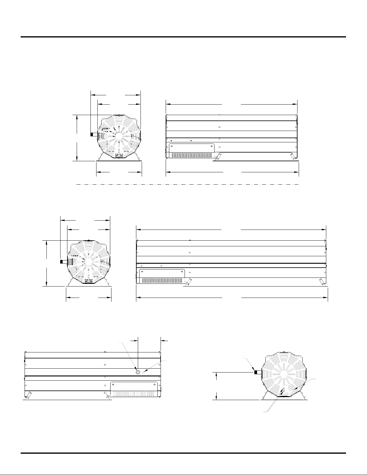
- Dimensional Details:
Note: All dimensions are in inches.
12.34
10.64
11.41
Model:
BPL-HAB20
32.52
11.25
12.34
10.64
11.41
11.25
- Gas and Electrical Connections:
Gas
Connection
5.41"
32.91
Model:
BPL-HAB40
BPL-HAB50
47.06
47.45
Electrical
Connection
6.56” BPL-HAB20
6.09” BPL-HAB40 & BPL-HAB50
Connection
Gas
Optional
Electrical
Connection
Note:
Connections shown
for all Models
BERNER PATIO+ Luminous
High and Low
Operation Lights
6 egaP
March, 2013
Page 7

Installation or repair should only be done by a qualified service person. The heater should be
inspected before use and at least annually by a qualified service person.
The appliance and its individual shutoff valve must be disconnected from the gas supply piping
system during any pressure testing of that system at test pressures in excess of ½ psig (3.5
kPa)
The appliance must be isolated from the gas supply piping system by closing its individual
manual shutoff valve during any pressure testing of the gas supply piping system at test
pressures equal to or less than ½ psig (3.5 kPa)
- Power & Gas Specifications
Gas Supply (Natural Gas ONLY)
Specifications
Important
HAB-M20 HAB-M40 HAB-M50
Rated Input
High Fire Rate 20,000 40,000 50,000
Low Fire Rate 15,000 32,000 42,000
Inlet Pressure
Maximum 14.0” W.C. 14.0” W.C. 14.0” W.C.
Minimum 7.0” W.C 7.0” W.C 7.0” W.C
Manifold Pressure
Maximum 6.2” W.C. 6.3” W.C. 6.3” W.C.
Minimum 3.0” W.C. 4.5” W.C. 4.5” W.C.
Inlet Connection
Electrical Supply
Alternating current AC, voltage; 24 V, 60 Hz with L, N and Ground (GND).
½” Male NPT
Note: 24V transformer not supplied.
BERNER PATIO+ Luminous
7 egaP
March, 2013
Page 8
Equipment
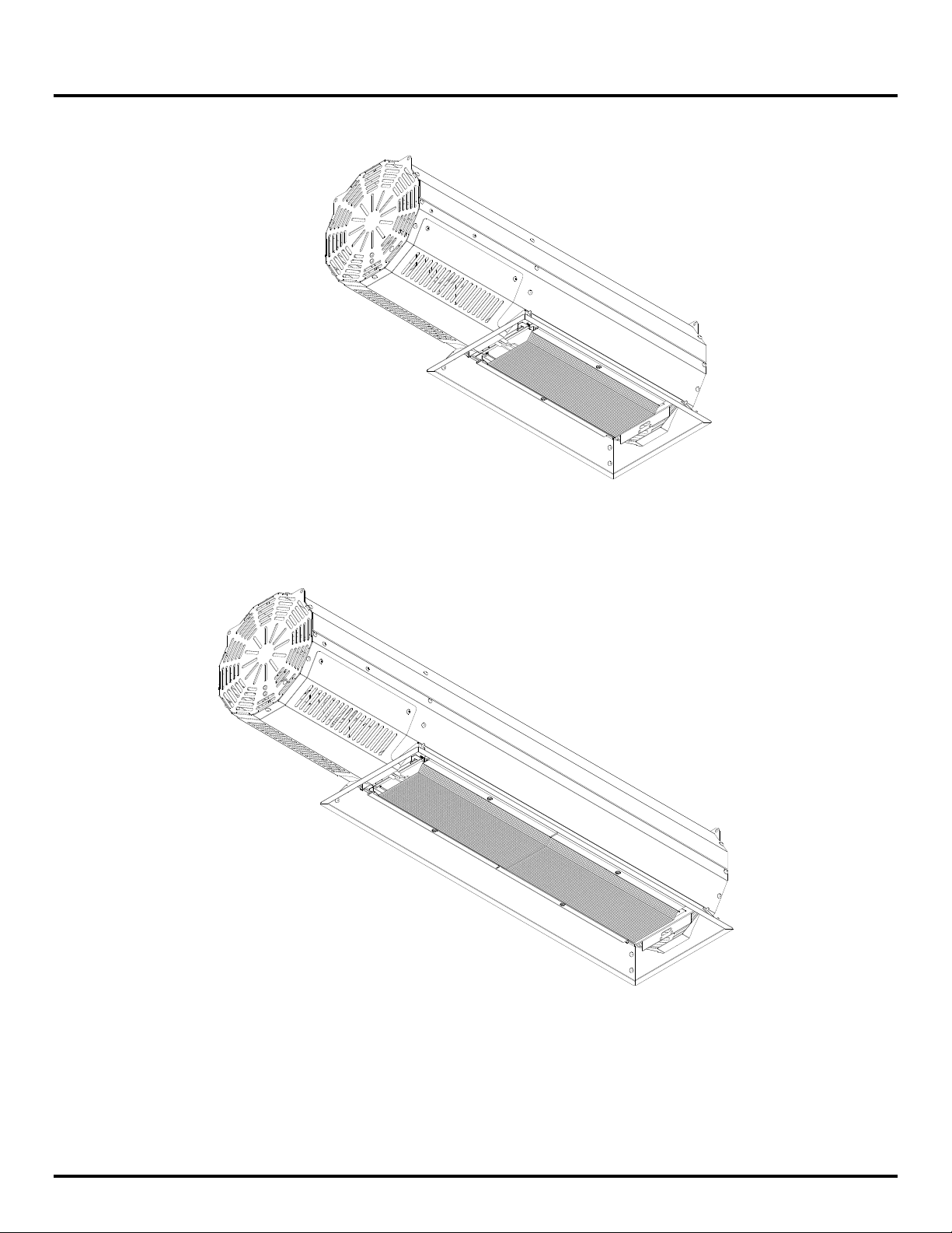
- Standard Equipment Included:
BPL-HAB20
BERNER PATIO+ Luminous
BPL-HAB40
BPL-HAB50
8 egaP
March, 2013
Page 9
Equipment
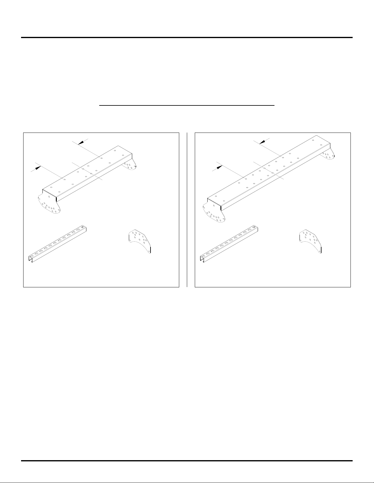
- Optional Equipment:
The following bolts are approved for installing this heater with the hanging brackets.
- 3/8” X 3” long Lag Bolts (minimum 4 per heater) with minimum 16.0” mounting spacing on centres.
- 3/8” X 3” Anchor Bolts (minimum 4 per heater) with minimum 16.0” mounting spacing on centres.
Optional Standard Ceiling / Wall Mounting Kits
16.0 Min.
Unistrut
18.0" Long
(QTY: 2)
BPL-HAB20
Hanging Bracket
Assembly
(QTY: 1)
Extension Arm
Hanging Bracket
(QTY: 2)
BPL-HAB40
BPL-HAB50
16.0 Min.
Unistrut
18.0" Long
(QTY: 2)
Hanging Bracket
Assembly
(QTY: 1)
Extension Arm
Hanging Bracket
(QTY: 2)
BERNER PATIO+ Luminous
9 egaP
March, 2013
Page 10

Equipment
Optional Equipment continued:
Optional Low Clearance Ceiling Mounting Kits
BPL-HAB20
Heat Shield
(QTY: 1)
Low Clearance
Mounting Bracket
(QTY: 2)
BPL-HAB40
BPL-HAB50
Hanging Bracket
Assembly
(QTY: 1)
Heat Shield
(QTY: 1)
Heat Shield
Mounting Bracket
(QTY: 4)
Extension Arm
Hanging Bracket
(QTY: 2)
Heat Shield
Mounting Bracket
(QTY: 4)
Optional Low Clearance NON COMBUSTIBLE Ceiling Mounting Kits
BPL-HAB40
BPL-HAB20
BPL-HAB50
Hanging Bracket
Assembly
(QTY: 1)
Hanging Bracket
Assembly
(QTY: 1)
BERNER PATIO+ Luminous
01 egaP
March, 2013
Page 11

Installation Instructions
- Clearance to Combustibles
A general clearance of 18” (0.5 m) in every direction is recommended for servicing only around
each Burner, also to ensure adequate air flow in and around the Heating System.
The stated clearance to combustibles represents a surface temperature of 90°F (50°C) above room
temperature. Building materials with low heat tolerance (such as plastics, vinyl siding, canvas, tri-
ply, etc…) maybe subject to degradation at lower temperatures. It is the installer’s responsibility
to assure that adjacent materials are protected from degradation.
In addition to this it is very important to observe the minimum clearance to combustibles at all
times to avoid any possibility of property damage or personal injury.
Table below lists the minimum clearance to combustible materials for various installation
configurations. Additional clearance may be required for glass, painted surfaces and other materials
which maybe damaged by radiant or convective heat.
Combustible materials
or other materials capable of being ignited and burned. Such materials shall be considered
combustible even though flame-proofed, fire-retardant treated or plastered.
Note with an ambient temperature of 70°F the surface temperatures at the clearance distances
listed below could reach 160°F, Care should be taken with placement of plastic or vinyl in the
proximity of the heater as they tend to distort and soften at these temperatures.
Adequate clearance to sprinkler heads must be maintained.
NOTE: Sprinkler head heat fuse link performance may alter with age.
NOTE: Some materials deteriorate or soften at sustained temperatures below 160°F.
are considered to be wood, compressed paper, plant fibres, plastics, Plexiglas
Consult material manufacturer for recommendations
BERNER PATIO+ Luminous
11 egaP
March, 2013
Page 12

Installation Instructions
Clearance to Combustibles Table
Model # Dim A Dim B Dim C Dim D Dim E Dim F Dim G Dim H
BPL-HAB20
BPL-HAB40
BPL-HAB50
A
C
B
9
13 75 34 48 10 16 66 9
13
47
75
D
17 29 8.5 9 38 3
34 48 10 16 66 9
F
E
30°
G
H
Optional Shield
Less than 30° mounting angle
Less than 30°
31.0” BPL-HAB40 & BPL-HAB50
18.0” BPL-HAB20
F
D
B
Dimensions in inches
C
21.0” BPL-HAB40 & BPL-HAB50
8.0” BPL-HAB20
BERNER PATIO+ Luminous
21 egaP
March, 2013
Page 13

Installation Instructions
- Installation Sequence:
The Habanero can be mounted either horizontally or at an incline of up to 30° as shown in the
clearance to combustibles table (previous section). A review of the job site will usually indicate a
logical installation location and order. However, time and expense can be saved if installation is
begun at the most critical dimension, watching for interference from overhead beams etc. Figure
below provides a general overview of the components utilized in the installation, as well as their
general relationship.
Caution: In areas where seismic forces are present extra / additional bracing may be required.
Caution: The heater must have a minimum clearance of 8 feet below, but less than 8 feet hanging
application can be considered as long as it meets local codes and minimum clearance to
combustibles.
Wall or Wood Post
Hanging Option
Ceiling Hanging
Option
BERNER PATIO+ Luminous
31 egaP
March, 2013
Page 14

Installation Instructions
- Ceiling / Wall Installation
Using Optional Standard Ceiling / Wall Mounting Kits
The mounting kits have provision for 0°, 15° and 30° mounting angles using the optional mounting
brackets. Figure below shows the possible angle configurations to install at desired angle.
Ceiling Installation for BPL-HAB20, BPL-HAB40 and BPL-HAB50.
Install Extension
using 5/16" X 3/4"
Hex Socket (Qty 4)
hardware supplied.
Note:
Minimum clearances to combustibles must be maintained
as per clearance to combustibles table when cutting
Unistrut.
Cut Unistrut to desired length,
and attach them to extension
brackets (as shown) using 1/2" X 1"
Cut to length
Hex Bolts (Qty 8)
hardware supplied.
holes for hanging
heater from CEILING.
Use these bolt
Step 2.
Step 1.
Arm brackets
(as shown)
Use these bolt
holes for hanging
heater from WALL.
Refer to the following
pages to mount heater
at 0°, 15° or 30° angle.
Secure Hanging Bracket Assembly
to ceiling / wall using 3/8" X 3" long
"Lag Bolt" or "Anchor Bolts"
(Qty 4) not included.
Step 4.
Attach heater to hanging
bracket assembly using
these bolt holes.**
Refer to the following
pages to mount heater
at 0°, 15° or 30° angle
BERNER PATIO+ Luminous
Step 3.
**Use these bolt
holes for hanging
heater from WALL.
41 egaP
March, 2013
Page 15

Installation Instructions
Using Optional Low Clearance Ceiling Mounting Kit BPL-HAB20 Only
Step 1.
Mount Low Clearance
Brackets to ceiling
using 3/8" X 3" long
"Lag Bolt" or "Anchor Bolt"
(Qty 4) not supplied.
31.0"
Step 2.
Install heat shield
mounting brackets
(as shown)
using 5/16" X 3/4"
Hex Socket (Qty 4)
hardware supplied.
Step 3.
Slide Heat Shield
over brackets
(as shown)
Step 4.
Attach heater to Brackets
as shown using 5/16" X 3/4" long
Hex Socket (Qty 4)
hardware supplied.
3.00
BERNER PATIO+ Luminous
51 egaP
March, 2013
Page 16

Installation Instructions
Using Optional Low Clearance Ceiling Mounting Kit BPL-HAB40 & BPL-HAB50 Only
Mount Hanging Bracket
Assembly to ceiling
using 3/8" X 3" long
"Lag Bolt" or "Anchor Bolt"
(Qty 4) not supplied.
Use these
two bolt holes
to attach bracket
to extension arm
refer to step 4.
Step 2.
Install heat shield
mounting brackets
(as shown)
using 5/16" X 3/4"
Hex Socket (Qty 4)
hardware supplied.
Step 1.
Install Extension
Arm brackets
using 5/16" X 3/4"
Hex Socket (Qty 4)
hardware supplied.
Use these
two bolt holes
to attach heater
to Hanging bracket
assembly
in step 1.
Slide Heat Shield
Step 3.
over brackets
(as shown)
Step 4.
(as shown)
9.00
Step 5.
Attach heater to
Brackets as shown
using 1/2" X 1" long
Hex Bolts (Qty 4)
hardware supplied.
BERNER PATIO+ Luminous
61 egaP
March, 2013
Page 17
Installation Instructions
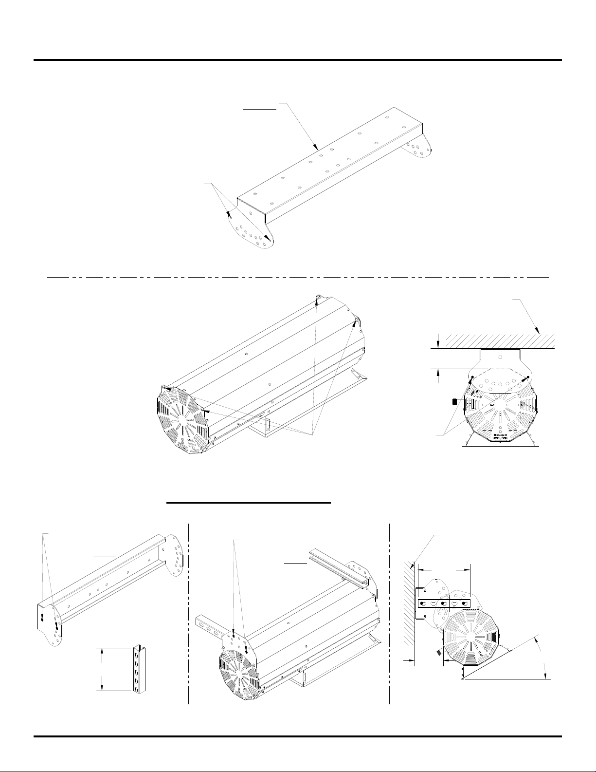
Using Optional Low Clearance NON COMBUSTIBLE Ceiling Mounting Kits (all models).
Step 1.
Secure Hanging Bracket Assembly
to ceiling / wall using 3/8" X 3" long
"Lag Bolt" or "Anchor Bolts"
(Qty 4) not supplied.
Attach heater to hanging
bracket assembly using
these bolt holes.
Step 2.
Attach heater to Brackets
as shown using 5/16" X 3/4" long
Hex Socket (Qty 4)
hardware supplied.
Attach heater to hanging
Installing Heater on a NON COMBUSTIBLE WALL
**Use these bolt
holes for hanging
heater from WALL.
Use these bolt
holes for hanging
heater from WALL.
Refer to the following
pages to mount heater
at 0°, 15° or 30° angle.
bracket assembly using
these bolt holes.
(all models).
Non Combustible
Ceiling
3.00
Non Combustible
Wall
10.00
Attach heater to
Brackets as shown
using 1/2" X 1" long
Hex Bolts (Qty 6)
hardware supplied.
Cut to 10.0" long
BERNER PATIO+ Luminous
5.41
71 egaP
March, 2013
30°
Page 18

Installation Instructions
- Angle Mounting Configurations:
The mounting kits have provision for 0°, 15° and 30° mounting angles using the optional mounting
brackets. Figure below shows the possible angle configurations to install at desired angle.
Ceiling Mount / Hanging Configuration
Left side
of bracket
Unistrut is fixed
to heater using
1
" X 1" Bolts (Qty 8)
2
(supplied with heater)
Note:
Other clearances must be maintained as per clearance to combustibles table.
30°
15°
0°
15°
Right side
of bracket
30°
Use these bolt
holes when
mounting heater
from ceiling
at any angle
Wall Mount / Hanging Configuration
Unistrut is fixed
to wall bracket using
1
" X 1" Bolts (Qty 8)
2
(supplied with heater)
Use these bolt
holes when
mounting from wall
at any angle.
Note:
Other clearances must be maintained as per clearance to combustibles table.
BERNER PATIO+ Luminous
Left side
of heater
81 egaP
0°
15°
30°
30°
15°
Right side
of heater
0°
March, 2013
Page 19

Installation Instructions
- BPL-HAB20 Installation:
Mounting heater at 0° from horizon.
The figure below shows the minimum mounting distances to achieve the clearance to combustibles.
Minimum Ceiling Mount Distance
Use these bolt
9.00
holes for positioning
at this angle.
Note:
Other clearances must be maintained
as per clearance to combustibles table.
Minimum Ceiling Mount Distance
using Optional Shield
3.00
Note:
Other clearances must be maintained
as per clearance to combustibles table.
BERNER PATIO+ Luminous
91 egaP
March, 2013
Page 20
Installation Instructions
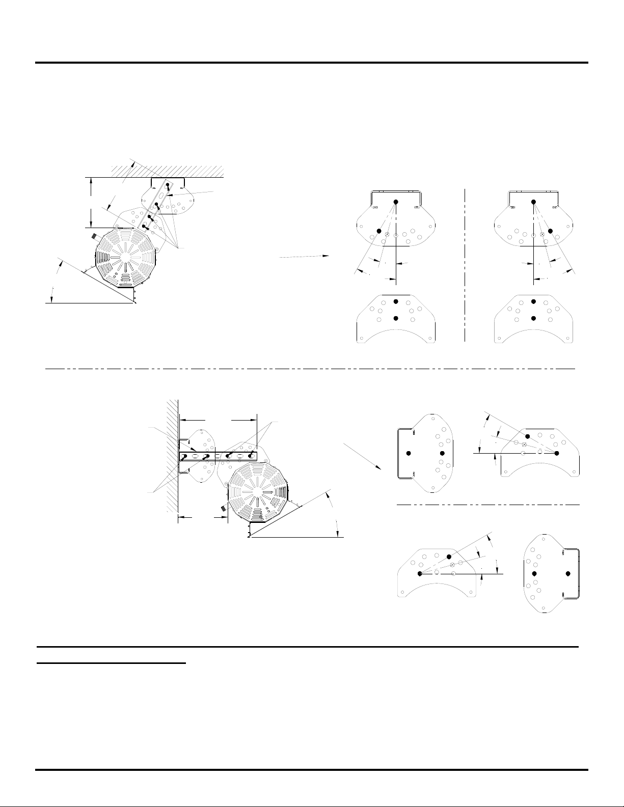
BPL-HAB20 Installation continued:
Mounting heater at 30° from horizon.
The figure below shows the minimum mounting distances to achieve the clearance to combustibles.
Minimum Ceiling Mount Distance
10.00
9.00
30°
LEFT side view
Note:
Other clearances must be maintained
as per clearance to combustibles table.
Cut unistrust to 13.75"
to achieve the minimum
clearances to combustibles
for this model
Cut unistrust to 10.00"
to achieve the minimum
clearances to combustibles
for this model
Use these bolt
holes for positioning
at this angle.
Minimum Wall Mount Distance
13.75
Use these bolt
holes for positioning
at this angle.
LEFT side view
15°
30°
RIGHT side view
15°
30°
LEFT side view
30°
15°
Use these bolt
holes for positioning
at this angle.
Note:
Other clearances must be maintained
as per clearance to combustibles table.
8.85
LEFT side view
30°
RIGHT side view
30°
15°
Note: When assembling hanging brackets the maximum angle the heater can be
at is 30° from horizon.
BERNER PATIO+ Luminous
02 egaP
March, 2013
Page 21

Installation Instructions
- BPL-HAB40 and BPL-HAB50 Installation:
Mounting heater at 0° from horizon.
The figure below shows the minimum mounting distances to achieve the clearance to combustibles.
Minimum Ceiling Mount Distance
Use these bolt
holes for positioning
at this angle.
13.00
Cut unistrust to 12.00"
to achieve the minimum
clearances to combustibles
for this model
12.00
Use these bolt
holes for positioning
at this angle.
Note:
Other clearances must be maintained
as per clearance to combustibles table.
9.00
Minimum Ceiling Mount Distance
using Optional Shield
Use these bolt
holes for positioning
at this angle.
Note:
Other clearances must be maintained
as per clearance to combustibles table.
BERNER PATIO+ Luminous
12 egaP
March, 2013
Page 22

Installation Instructions
BPL-HAB40 and BPL-HAB50 Installation continued:
Mounting heater at 30° from horizon.
The figure below shows the minimum mounting distances to achieve the clearance to combustibles.
Minimum Ceiling Mount Distance
18.00
16.00
30°
LEFT side view
Cut unistrust to 13.75"
to achieve the minimum
clearances to combustibles
for this model
Cut unistrust to 18.00"
to achieve the minimum
clearances to combustibles
for this model
Use these bolt
holes for positioning
at this angle.
Note:
Other clearances must be maintained
as per clearance to combustibles table.
Minimum Wall Mount Distance
13.75
Use these bolt
holes for positioning
at this angle.
LEFT side view
15°
30°
RIGHT side view
15°
30°
LEFT side view
30°
15°
Use these bolt
holes for positioning
at this angle.
10.00
LEFT side view
30°
Note:
Other clearances must be maintained
as per clearance to combustibles table.
RIGHT side view
30°
15°
Note: When assembling hanging brackets the maximum angle the heater can be
at is 30° from horizon.
BERNER PATIO+ Luminous
22 egaP
March, 2013
Page 23

Installation Instructions
- Gas Connection / Code Requirements
Installation must comply with local building codes and/or, for the USA/National Fuel Gas Code, ANZI
Z 223.1 (NFPA 54) and for Canada, CAN/CGA B149.1 and B149.2, National Gas and Propane
Installation Code (latest editions).
Do not use high pressure (above ½ psig) to test the gas supply system with the appliance connected.
Failure to comply can result in damage to the appliance.
Check for gas leaks at all connections with appropriate soap solution.
Never connect an unregulated gas supply to the heater.
BERNER PATIO+ Luminous
32 egaP
March, 2013
Page 24

Installation Instructions
- Electrical Connection / Code Requirements
The Habanero Heaters require 24VAC power supply (transformer to be supplied by installer). In all
cases, heaters must be electrically grounded in accordance with local codes or in their absence, the
National Electric Code, ANSI/NFPA 70 in the US, and the Canadian Electric Code, CSA C22.1.
Heaters may also be controlled with a manual line switch or timer switch in place of the thermostat.
Refer to wiring diagrams below for guidance on electrical wiring of heaters.
If any of the original wire as supplied with the heater must be replaced, it must be replaced with wiring
having a rating of at least 105°C temperature service and 600 volts capability.
Internal wiring diagram.
Gas Valve
Channel Module 50X-24
Brown
Red
Pink
Green
C C
M HI
Brown
Brown
Yellow / Green
Pink
Black
Low-Fire
Light
Blue
Yellow
Red
Green
Green
SENSOR
IGNITER
Hi-Fire
Light
Blue 24 VAC (Hi)
Red
24 VAC (Lo)
Green
BURNER
Note:
If any of the original wire as supplied with the appliance must be replaced, it must
be replaced with wiring material having a temperature rating of at least 105°C.
BERNER PATIO+ Luminous
42 egaP
March, 2013
Page 25

Installation Instructions
External wiring Options. (Manual line switch with Hi-Lo or Two Stage Switch)
Manual Line Switch with Hi-LO wiring diagram
Notes:
- Allow Min. contact rating of
1AMP per heater inductive.
- Allow 20VA / 24V. transformer
per heater.
24 Volt
Transformer
115 VAC
Grounded
Supply
On
Off
24 Volt
AC Supply
**Ensure A Good
Ground Source
Hi (on)
Low (On)
Blue
Red
Green
To Patio Heater
Notes:
- Max. 5 heaters per 1 switch
- Allow 20VA / 24 V. transformer
per heater.
- Switch part numbers can be
found in the Parts List section.
24 Volt
Transformer
115 VAC
Grounded
Supply
Two Stage Switch wiring diagram
Back Box
1X
NC 1
NO 3
4X
2 2
24 Volt
AC Supply
**Ensure A Good
Ground Source
Blue
Red
Front Cover
(Hi)
(Low)
To Patio Heater
Green
BERNER PATIO+ Luminous
52 egaP
March, 2013
Page 26

Installation Instructions
- Venting
This heater does not require venting.
WARNING!
This heater is NOT approved for any indoor Residential
application. If in doubt of your application consult with your
local fire marshal or gas authority having jurisdiction. Indoor
spaces include but are not limited to attached garages,
solariums, living quarters etc.
BERNER PATIO+ Luminous
62 egaP
March, 2013
Page 27

Lighting & Shutdown Instructions
- Lighting
1. Open manual gas supply valve (ensure gas supply lines have been purged).
2. Turn on switch to energize electric supply.
3. The electronic control module will time begin the ignition period in 3 seconds.
4. The gas valve will open and ignition spark will commence and continue for 20 sec.
5. If flame starts and “is detected”, flame will continue until turned off.
6. If no flame is detected, the gas valve will close after 20 sec. A “wait’ period commences and
lasts approximately 5 sec. and a second trial for combustion commences. The electronic
control will attempt three trials for ignition before locking out for approximately 1 hour at which
time it will automatically try again.
Electronic control of heater can be re-set by de-energizing and re-energizing electric power.
- Shut Down
1. Turn off power to electronic control.
2. For longer periods of shut down, also close manual gas supply valve.
Note:
It is recommended to use a factory recommended “Hi-Lo switch” with this heater.
BERNER PATIO+ Luminous
72 egaP
March, 2013
Page 28

Maintenance & Trouble Shooting
- Maintenance
For best performance, the certain minimal maintenance procedures should be performed before each
heating season:
• A service agency qualified to adjust and repair infrared heaters should be engaged for service
other than routine maintenance.
• Before performing any services or maintenance, shut off gas and electrical supply to heater.
• Keep the appliance area clear and free from combustible materials, gasoline and other
flammable vapours and liquids.
• Do not obstruct the flow of combustion and ventilation air.
• Check condition of burner. Remove any foreign objects or debris from burner.
• Inspect the igniter. Replace igniter if there is excessive wear or erosion, breakage or other
defects.
• The reflector sections may be cleaned by wiping with a damp cloth.
• Annually verify hose gas supply in heater post and all connections for gas leaks.
- Trouble Shooting
No Gas Supply at Burner
• Ensure manual shut off valve is in proper position
• Ensure there is pressure and flow at inlet to gas valve.
• Ensure gas valve gets 24v power from control module during ON cycle.
No Spark
• Ensure control module has 24VAC supply
• Ensure spark electrode assembly is grounded and there are no cracks in ceramic insulator.
Flame Lights but Will Not Stay Lit
• Ensure there is no overpowering wind.
• Ensure sense electrode is not corroded, is not grounded or has a cracked insulator. Electrode
position is radially across face of burner.
BERNER PATIO+ Luminous
82 egaP
March, 2013
Page 29
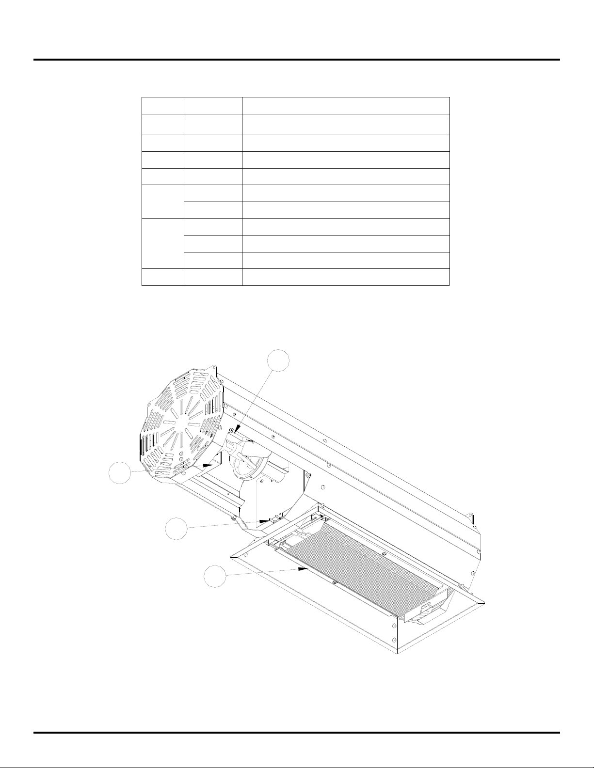
- Replacement Parts
Parts List
Item # Part #
1
2
3 EE009
4 EG001
5
6*
7*
HE001
CE006
HG034
HG035
SE004
SE009
SE010
EE020
Description
Spark Electrode
Ignition Wire (not shown)
Electronic Ignition Module
Gas Valve NAT
Burner Assembly HAB-M20
Burner Assembly HAB-M40 and HAB-M50
20VA 24V Transformer (not supplied)
40VA 24V Transformer (not supplied)
100VA 24V Transformer (not supplied)
Two Stage Switch
3
4
BERNER PATIO+ Luminous
1
5
92 egaP
March, 2013
Page 30

Warranty
BPL-HAB PATIO HEATER
WARRANTY
The Manufacturer warrants to the original owner that the product will be free of defects in
material and workmanship for a period of 5 years from the date of purchase, for everything
except the electronic control module, spark electrode, and sense electrodes which have a
replacement warranty period of 3 years.
The Manufacturer’s obligation under this warranty is limited to repair or replacement; FOB its
facility, of the defective part. In the case of replacement parts the warranty period shall be
the longer of the original warranty or a period of 12 months from the date of purchase. In no
event shall the Manufacturer be liable for incidental expense or consequential damages of
any kind.
This warranty does not cover any shipping, installation or other costs incurred in the repair or
replacement of the product. No materials will be accepted for return without authorization.
This warranty will not apply if, in the judgement of the Manufacturer, the equipment has been
improperly installed,
This warranty will not apply to damage to the product when used in corrosive atmospheres.
No person is authorised to assume for the Manufacturer any other warranty, obligation or
liability.
THE REMEDIES PROVIDED FOR IN THE ABOVE EXPRESS WARRANTIES ARE THE
SOLE AND EXCLUSIVE REMEDIES. NO OTHER EXPRESS OR IMPLIED WARRANTIES
ARE MADE INCLUDING, BUT NOT LIMITED TO, ANY IMPLIED WARRANTY OF
MERCHANTABILITY OR FITNESS FOR A PARTICULAR USE OR PURPOSE.
unreasonably used, damaged or modified.
Berner International Corp.
111 Progress Ave., New Castle, PA 16101
www.berner.com
BERNER PATIO+ Luminous
03 egaP
March, 2013
 Loading...