

Berner CLC08-1042 Installation Manual
IMPORTANT INSTRUCTIONS
Saving energy and creating healthy, comfortable environments
READ AND SAVE
THESE INSTRUCTIONS
No. II-480
Date July, 2015
SANITATION
CERTIFIED
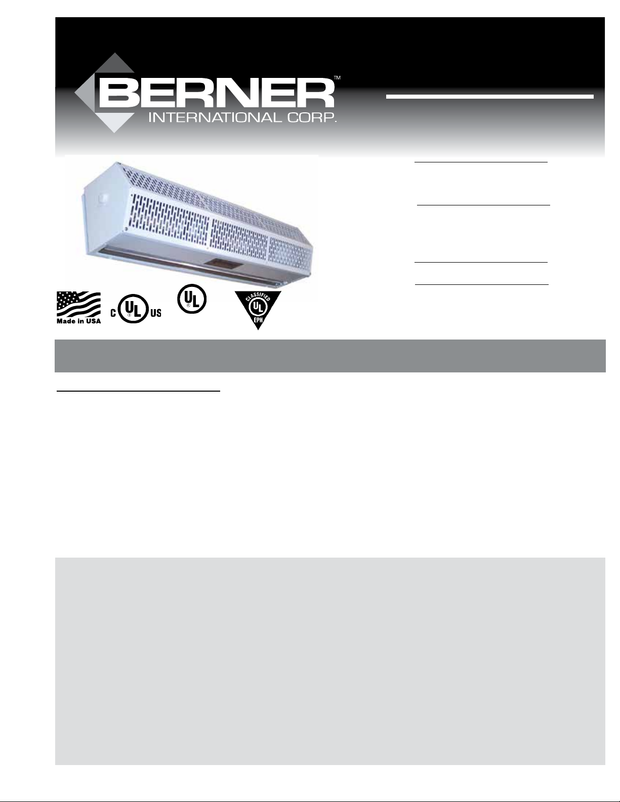
Low Prole 7
AIR CURTAIN SERIES SLC07
for outdoor use
SLC07
ANSI/NSF 37
Air Curtain Fans
for Customer Entry
max.mounting
height is 7’
SLC07
COMMERCIAL
Low Prole 8
AIR CURTAIN SERIES CLC08
Installation & Maintenance Instructions
TABLE OF CONTENTS
I. UNCRATING............................................................................................................................................................. 2
II. MOUNTING INSTRUCTIONS................................................................................................................................ 2
III. WALL MOUNTING................................................................................................................................................ 2
IV. SUSPENDED MOUNTING.................................................................................................................................... 3
V. ELECTRICAL CONNECTIONS .............................................................................................................................. 3
VI. MECHANICAL CONNECTIONS .......................................................................................................................... 5
VII. AIRFLOW ADJUSTMENTS ................................................................................................................................. 5
VIII. MAINTENANCE AND CLEANING .................................................................................................................... 6
IX. SERVICE ................................................................................................................................................................ 6
X. TROUBLESHOOTING ............................................................................................................................................ 7
XI. WARRANTY .......................................................................................................................................................... 8
WARNING: TO REDUCE THE RISK OF FIRE, ELECTRIC SHOCK OR INJURY TO PERSONS, OBSERVE THE FOLLOWING:
A. Read all instructions before installing or using this air curtain.
B. Use this unit only in the manner intended by the manufacturer and described in this manual. Any other use not recommended by the manufacturer may cause re, electric shock,
or injury to persons. If you have any questions, contact the manufacturer.
C. Before servicing or cleaning unit, switch power o at service panel and lock the service disconnecting means to prevent power from being switched on accidentally. When the
service disconnecting means cannot be locked, securely fasten a prominent warning device, such as a tag, to the service panel.
D. Installation work and electrical wiring must be done by qualied person(s) in accordance with all applicable national and local codes having jurisdiction, including re-rated
construction. See page 3, ELECTRICAL CONNECTIONS (NEC Code ANSI/NFPA No. 70).
E. When cutting or drilling into wall or ceiling, do not damage electrical wiring and other hidden utilities.
F. To reduce the risk of re, do not store or use gasoline or other ammable vapors and liquids in the vicinity of the air curtain.
G. This air curtain is hot when in use. To avoid burns, do not let bare skin touch hot surfaces. Keep combustible materials, such as furniture, pillows, bedding, papers, clothes, etc. and
curtains at least 1 inch from the top, back, front, sides and at least 6 feet from the discharge of the air curtain.
H. Extreme caution is necessary when any air curtain is used by or near children or invalids, and whenever the heater is left operating unattended.
I. Do not operate any air curtain after it malfunctions. Disconnect power at the service panel and have the air curtain inspected by a reputable electrician before reusing.
J. To disconnect the air curtain, turn controls to “o”, and turn o power to the air curtain circuit at main disconnect panel.
K. Do not insert or allow foreign objects to enter any ventilation or discharge opening as this may cause an electric shock or re, or damage the air curtain.
L. To prevent a possible re, do not block the air intake or discharge of the air curtain in any manner.
M. The air curtain has hot and arcing or sparking parts inside. Do not use it in areas where gasoline, paint, or ammable vapors or liquids are used or stored.
N. This heater may include an audible or visual alarm to warn that parts of the heater are getting excessively hot. If the alarm sounds (or illuminates), immediately turn the heater
o and inspect for any objects on or adjacent to the heater that may have blocked the airow or otherwise caused high temperatures to have occurred.
DO NOT OPERATE THE HEATER WITH THE ALARM SOUNDING (OR ILLUMINATING).
-1-
I. UNCRATING THE AIR CURTAIN UNIT
Carefully examine the carton(s) for damage before opening. If the carton
is damaged, immediately notify the shipping company. If the unit(s)
were shipped on wooden skids, remove protective wood and banding
straps securing the carton(s) to the skid. Open the carton(s) and remove
all protective packaging. Remove the plastic cover housing by lifting
vertically. Remove and discard four (4) nuts and washers holding the motor/blower section to the bottom of the carton. Remove motor/blower
section from the carton.
CAUTION: ONLY LIFT THE UNIT BY GRASPING INLET RINGS ON THE
BLOWER HOUSING WITHOUT TOUCHING BLOWER WHEELS.
Immediately verify that the electrical rating nameplate located on the
cover matches electrical power supply available. Retain the shipping
carton(s) until the unit(s) are installed and properly operating.
ACCESSORIES: If the unit(s) were ordered with optional electrical accessories (door switch, control panel, etc.), the accessories may be found in
the carton containing the unit or in a separate carton(s) accompanying
the unit(s). Check all of the cartons/skids for accessories before discarding.
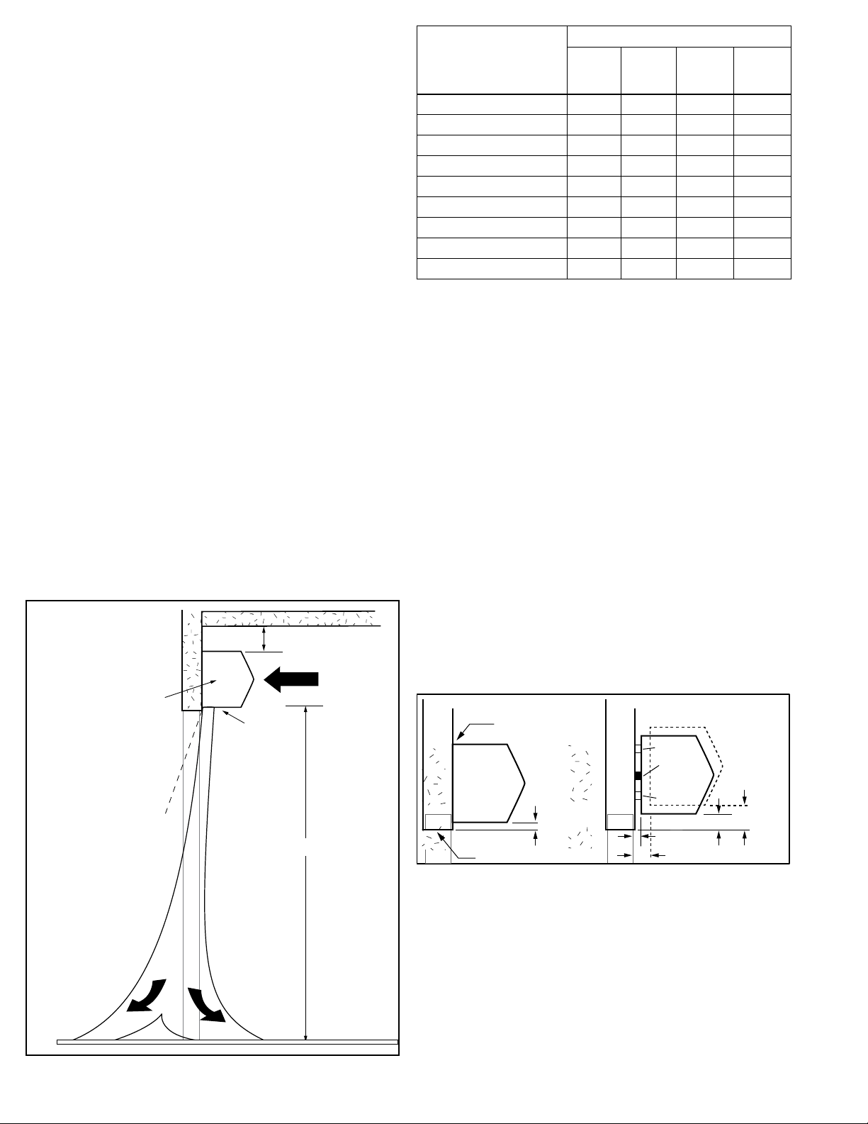
II. MOUNTING INSTRUCTIONS (General)
The Certied Low Prole 7/Commercial Low Prole 8 air curtain
is designed to be an eective barrier against cold drafts in the
winter and hot air in the summer, ying insects and airborne
contaminants. To achieve optimum protection, the unit should
be mounted on the inside of the building, ush to the wall and as
close to the top of the door opening as possible. To ensure peak
performance, keep air stream free of obstructions.
The air curtain will not perform properly if negative air pressure exists in the building. Under these conditions, a means
for make-up air to the building must be provided so that the
air pressure on both sides of the opening is in balance.
1” minimum
1” minimum
side clearance from
combustible materials.
Discharge
Nozzle
20˚
AIR
6' minimum*
Net Weight (lbs)
MODEL
SLC07
Ambient
CLC08
Ambient
CLC08
Electric
CLC08
St/Hw
SLC07-1036, CLC08-1036 35 41 48 67
SLC07-1042, CLC08-1042 38 45 53 74
SLC07-1048, CLC08-1048 42 48 58 80
SLC07-1060, CLC08-1060 49 56 67 94
SLC07-1072, CLC08-1072 56 64 77 107
SLC07-2084, CLC08-2084 76 90 105 138
SLC07-2096, CLC08-2096 84 98 115 152
SLC07-2108, CLC08-2108 91 105 123 164
SLC07-2120, CLC08-2120 98 113 137 177
TABLE 1 - Weight Chart
Before mounting the unit, check the supporting structure to verify
that it has sucient load-carrying capacity to support the weight
of the unit(s). The mounting hardware (supplied by others) should
be capable of supporting a minimum of three (3) times the weight
of the unit. See TABLE 1.
A. When determining the mounting location for the unit(s), make
sure that nothing interferes with the curtain of air developed
when the discharge vanes are directed from 0° to 20° toward
the door opening. If the air stream strikes any obstruction
(the top edge of the doorway, a door opening device, etc.),
the eectiveness of the unit will be greatly reduced.
See FIGURE 1.
B. For optimum performance, the bottom of the unit (discharge
nozzle) should be no more than 1” above the top of the door
opening with the unit mounted ush to the wall. If the unit
must be mounted higher, it must be spaced out from the wall
3
/8” for every inch the unit is above the door opening. Any
void between the air curtain and the wall should be sealed
along the full length of the unit. See FIGURE 2.
C. Proceed to: Section III-WALL MOUNTING or
Section IV-SUSPENDED MOUNTING
Flush Mounting
Spacer
Seal
AIR
CURTAIN
1" max.
Top of Doorway
FIGURE 2 - Positioning of Air Curtain
AIR
CURTAIN
Spacer
3/8"
3/4"
3"
2"
EXTERIOR
*Electrically Heated Units Only
FIGURE 1 - Air Stream
INTERIOR
R
A
I
I
A
R
-2-
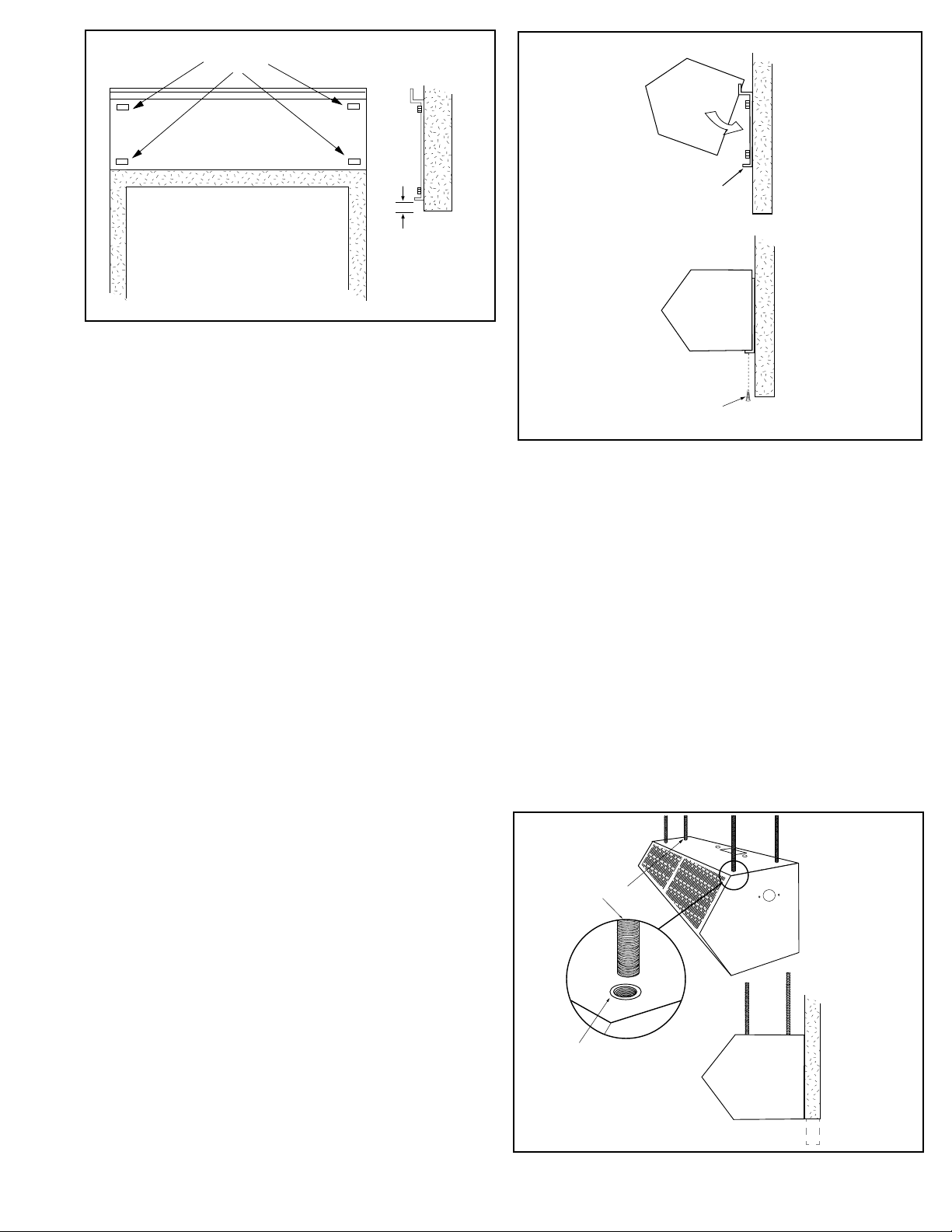
Recommended Mounting
Plate Holes
Doorway Opening
1" max.
Doorway
Opening
FIGURE 3 - Positioning of Mounting Plate
III. WALL MOUNTING
A. Determine the location on the wall above the opening where
the air curtain will be mounted. This location should center
the unit over the opening and provide suitable mounting
support. It is recommended to use at least four locations that
correspond to the outer corners of the wall mounting plate.
See FIGURE 3.
B. Prepare the wall as necessary for the wall mounting
plate anchors (by others).
C. Drill holes in the wall mounting plate to correspond to the
locations on the wall.
D. Anchor the wall mounting plate over the door opening with
the mounting tabs pointing upwards.
E. Raise the unit over the door (air nozzle facing down) and onto
the mounting plate. Tilt the unit upward, matching the holes
in the frame with the tabs on the mounting plate.
See FIGURE 4.
F. Lower the unit into place allowing it to rest on the mounting
plate. The unit ange should rest above the mounting plate
ange.
G. After the unit is securely seated to the mounting plate, install
the locking screws along the bottom ange. See FIGURE 4.
H. Proceed to Section V-ELECTRICAL CONNECTIONS
Mounting Plate
Lower Lip
Locking Screws
FIGURE 4 - Attaching Unit to Mounting Plate
IV. SUSPENDED MOUNTING
(Ceiling Suspension)
A. When the unit is top mounted, the wall mounting plate is
designed to store on the back of unit for future use.
B. Four (4) factory installed #10-24 threaded inserts are located
on the top of the unit for top suspension mounting.
See FIGURE 5.
C. Determine the exact mounting location of the air curtain.
D. The top of the unit is provided with an electrical knockout
for power connection. Remove the wiring tray compartment
cover. Remove the knockout and attach necessary electrical
hardware. Save the wiring diagram found inside of wiring
tray.
E. Attach #10-24 threaded rods, or other suitable hardware to
the top mounted threaded inserts.
F. Proceed to Section V-ELECTRICAL CONNECTIONS
-3-
Suspension Rods
10-24 Threaded Insert
Side View
FIGURE 5 - Suspended Mounting
 Loading...