

Berko HUHAA, HUHAA320, HUHAA324, HUHAA327, HUHAA348 Installation, Operation & Maintanance Instructions
...Page 1
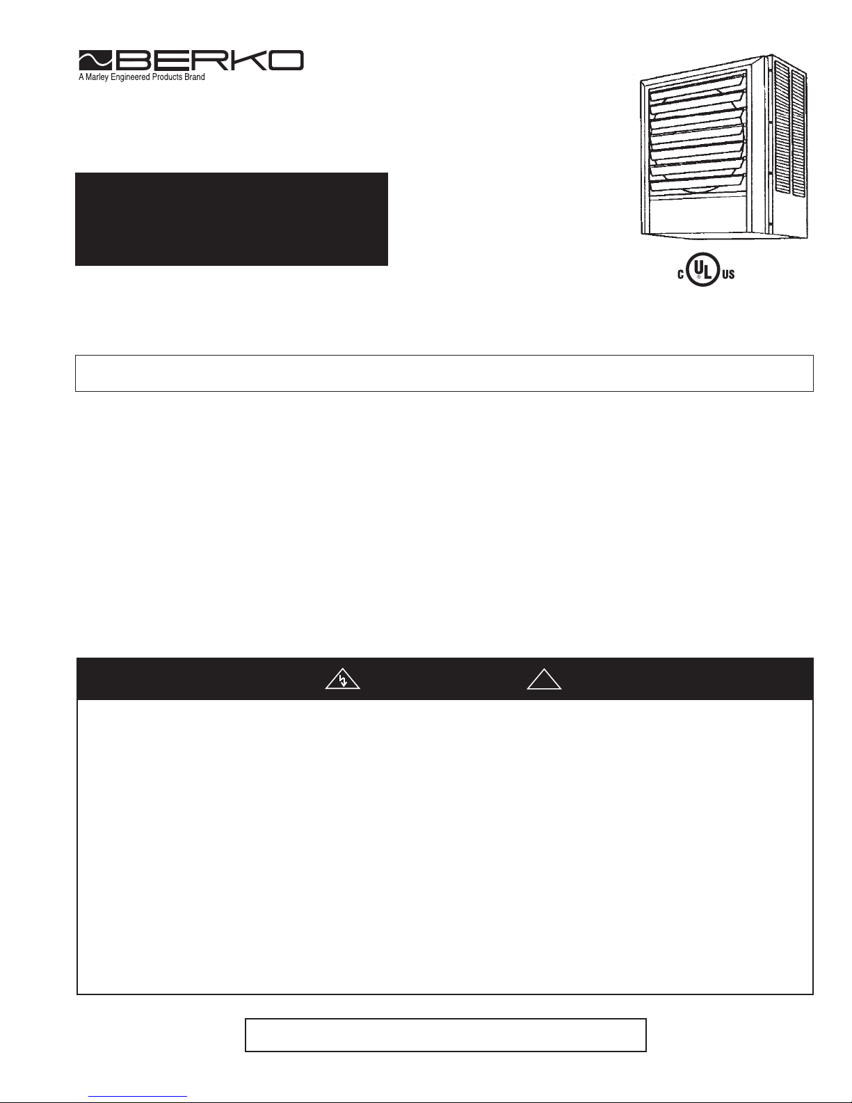
HUHAA Series
Modular Unit Heaters
FILE #E21609
Installation, Operation & Maintenance Instructions
Dear Owner,
Congratulations! Thank you for purchasing this new heater manufactured by Marley Engineered Products.
You have made a wise investment selecting the highest quality product in the heating industry.
Please carefully read the installation and maintenance instructions shown in this manual. You should enjoy
years of efficient heating comfort with this product from Marley Engineered Products... the industry’s leader in
design, manufacturing, quality and service.
... The Employees of
Marley Engineered Products
WARNING
Read Carefully prevent difficulties that might arise during installation of
heaters. Studying the instructions first may save you
considerable time and money later. Observe the following
procedures, and cut your installation time to a minimum.
1. To prevent electrical shock, disconnect all power coming to heater
at main service panel before wiring or servicing.
2. All wiring must be in accordance with the National and Local
Electrical Codes and the heater must be grounded as a precaution
against possible electric shock.
3. Verify the power supply voltage coming to heater matches the
ratings printed on the heater nameplate before energizing.
4. This heater is hot when in use. To avoid burns, do not let bare skin
touch hot surfaces.
These instructions are written to help you
SAVE THESE INSTRUCTIONS
!
5. Do not insert or allow foreign objects to enter any ventilation or
exhaust opening as this may cause an electric shock, fire,or dam-
age to the heater.
6. To prevent a possible fire, do not block air intakes or exhaust in any
manner. Keep combustible materials, such as crates, d r a p e s ,
etc., away from heater. Do not install behind door, furniture,
towels, or boxes.
7. A heater has hot and arcing or sparking parts inside. Do not use it
in areas where gasoline, paint or flammable liquids are stored.
8. Use this heater only as described in this manual. Any other use not
recommended by the manufacturer may cause fire, electric shock,
or injury to persons.
9. This heater is not approved for use in corrosive atmospheres such
as marine, green house or chemical storage areas.
Page 2
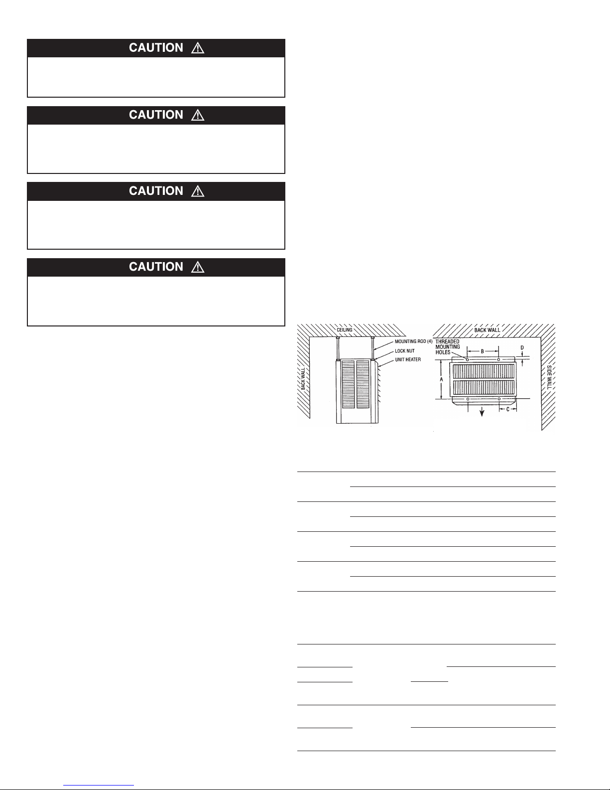
THE HEATER MUST BE MOUNTED AT LEAST 7' (2134MM)
ABOVE THE FLOOR TO PREVENT ACCIDENTAL CONTACT
WITH THE FAN BLADE WHICH COULD CAUSE INJURY.
THE CEILING MOUNTING STRUCTURE AND THE ANCHORING PROVISIONS MUST BE OF SUFFICIENT STRENGTH
TO SUPPORT THE COMBINED WEIGHT OF THE HEATER
AND MOUNTING BRACKET. (SEE TABLE 4).
ALL BUILT-IN THERMOSTATS: IF THE HEATER IS USED TO
PREVENT PIPING OR LIQUIDS FROM FREEZING, AND IF
THE THERMOSTAT IS SET BELOW 45° F (7°C), THE FAN
MUST RUN CONTINUOUSLY.
TO PREVENT POSSIBLE OVERHEATING OR DAMAGE DUE
TO OVERHEATING, KEEP AT LEAST 5' (1524MM) CLEARANCE IN FRONT OF HEATER. REFER TO TABLE 1 FOR
SIDE, TOP, AND BACK CLEARANCE REQUIREMENTS.
MOUNTING THE HEATER, GENERAL
The heater may be mounted to discharge the heated air either
horizontally or vertically. When the heater is mounted for vertical
discharge, it is recommended that the heater be positioned so
that the access door will open away from the wall to provide
greater access to the wiring and control compartment. If the
heater is to be mounted with the access door facing a wall, the
heater must be mounted far enough from that wall to allow full
opening of the access door (a distance approximately equal to
the width of the heater, check clearance before installing).
Refer to Table 1 for wall and ceiling clearances before mounting
heater.
The heater may be mounted for either vertical or horizontal discharge by the use of threaded rods. (Refer to Table 2 for threaded rod sizes required.) Observe the detailed procedures in the
following installation instructions.
The heater may also be suspended from the wall or ceiling by
means of an optional mounting bracket (type HUHAAB or
HCMB) which permits horizontal pivoting of the heater.
After the heater is installed, the louvers may be positioned to
direct the heated air in the desired direction. When the heater is
installed for horizontal discharge, the louvers should direct the
air either straight ahead or downward. Directing the air upward
may cause the heated air to remain in the ceiling area and
waste energy.
DO NOT MOUNT MERCURY TYPE THERMOSTAT DIRECTLY
ON UNIT. VIBRATION COULD CAUSE HEATER TO
MALFUNCTION.
MANUAL RESET LIMIT
(FACTORY INSTALLED OPTION
ONLY.) THE LIMIT SWITCH IS LOCATED INTERNALLY ON
THE REAR OF THE HEATER. ON THE 3KW AND 5KW
MODELS, THE ACCESS TO THE RESET BUTTON IS ON THE
RIGHT SIDE (WHEN FACING REAR OF HEATER); ON ALL
OTHER MODELS IT IS NEAR THE TOP REAR OF THE
HEATER.
THE MANUAL RESET LIMIT IS IN SERIES WITH THE AUTOMATIC RECYCLING PROTECTOR (LIMIT). THE MANUAL
RESET LIMIT WILL NOT RESET UNTIL THE HEATER HAS
COOLED AND THE BUTTON IS PUSHED IN.
HEATER LOCATION INSTRUCTIONS
Arrange units so their discharge air streams:
a.
are subjected to a minimum of interference from columns,
machinery and partitions;
b.
wipe exposed walls without blowing directly at them;
c.
are directed away from room occupants in comfort heating;
d.
are directed along the windward side when installed in a
building exposed to a prevailing wind.
Locate thermostats approximately 5' (1524mm) above the floor
on interior partition walls or posts, away from cold drafts, internal
heat sources and away from heater discharge air streams.
Small rooms can be heated by one unit heater.
Large rooms require multi-unit installations. Number and
capacity of units will be determined by volume of building and
square feet of floor area to be heated. Arrange units to provide
perimeter air circulation where each unit supports the air stream
from another.
(TOP VIEW)
Figure 1. Horizontal Discharge Mounting and Spacing.
Table 1. Wall and Ceiling Clearance, inches (mm)
Unit Discharge Ceiling Side Wall Back Wall
3 & 5 kW
7.5 to 10 kW
15 to 10 kW
25 to 50 kW
Horiz. 2 (50.8) 6 (152.4) 9 (228.6)
Vert. 6 (152.4) 18 (457.2) 18 (457.2)
Horiz. 6 (152.4) 6 (152.4) 13 (330.2)
Vert. 6 (152.4) 24 (609.6) 24 (609.6)
Horiz. 6 (152.4) 9 (228.6) 12
Vert 6 (152.4) 24 (609.6) 24 (609.6)
Horiz. 16 (406.4) 12 (304.8) 18
Vert. 12 (304.8) 36 (914.4) 36 (914.4)
Table 2. Rod Thread and Spacing Dimensions, inches (mm)
for Horizontal Discharge
Rod Thread
Unit Type A B C D
3 - 5 kW
7.5 - 10 kW
15 - 20 kW
25 - 30 kW
40 - 50 kW
5
/16- 18
3
/8- 16
6 4
61/
(153.9)
11
(289.0)
10
(268.2) (368.3) (157.2) (16.0)
15 15/
(404.9) (368.3) (157.2) (16.0)
(152.4) (103.1) (19.0)
16
87/
3
/
8
9
/
16
16
8
(225.6) (130.3) (19.0)
14 1/
14 1/
1
/
16
5 1/
8
6 3/
2
2
6 3/
16
16
1
/2(317.5)
1
/2(470.0)
3
/
4
3
/
4
5
/
8
5
/
8
2
Page 3
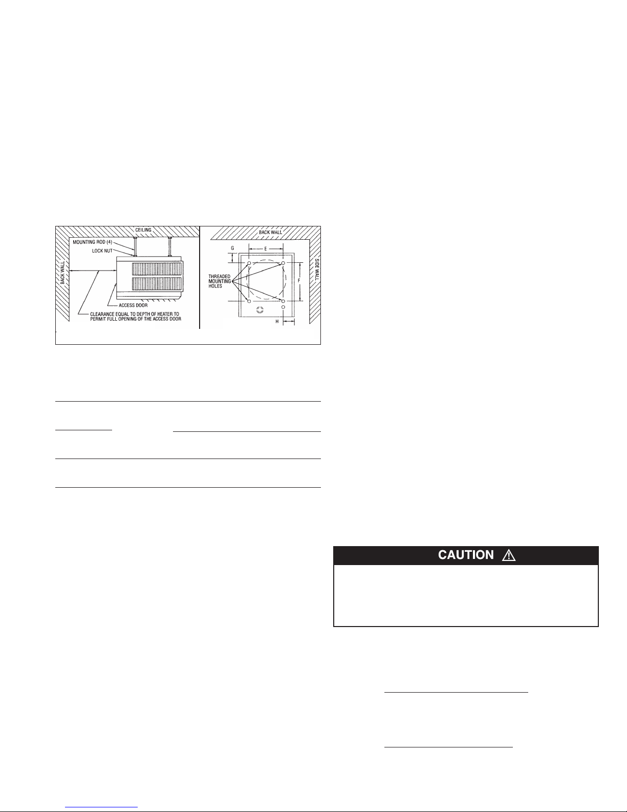
Horizontal Discharge (Rod-mount from Ceiling)
1. Install four threaded mounting rods in the threaded holes and
secure in place using lock nuts. (See Table 2).
2. Securely attach the four mounting rods to the ceiling. (Refer
to Table 1 for wall and ceiling clearances, and Table 2 for
mounting rod spacing).
Vertical Discharge (Rod-Mount from Ceiling)
1. Remove bolts from the threaded holes in the back of the
heater.
2. Install four threaded mounting rods in the threaded holes and
secure in place using lock nuts.
3. Securely attach the four mounting rods to the ceiling. (Refer
to Table 1 for wall and ceiling clearances, and Table 3 for
mounting rod spacing dimensions.)
(TOP VIEW)
Figure 2. Vertical Discharge Mounting and Rod Spacing
Table 3. Rod Thread Type and Spacing Dimensions, inches (mm)
for Vertical Discharge
Rod Thread
Unit Type E F G H
3 - 5 kW
7.5 - 20 kW
25 - 30 kW
5
/16- 18
3
/8- 16
69
(152.4) 247.7) (50.8) (103.1)
7
8
/
8
(225.6) (371.6) (50.8) (130.3)
1
14
/
(308.1) (539.8) (55.6) (157.2)
3
/
4
145/
211/
2
8
4
24
25
23/
16
63/
1
/
16
1
/
8
16
WIRING
Branch Circuit (Power)
1. Connect heater only to the voltage, amperage and frequency
specified on the nameplate.
2. Field wiring must be properly sized to carry the amperage in
accordance with the NEC.
3. The access door is hinged. There are either one or two
screws accessible from the bottom, that must be removed to
gain access.
4. A knockout is provided in the back of the heater close to the
power terminal block and the control terminal board. The
control terminal board knockout is 1/2 inch (12.7 mm) conduit
size. The power terminal block knockout is multiple diameter. Use the diameter that fits the required conduit size.
5. A ground terminal is provided near the power terminal board.
The ground wire should be connected before other connections are made.
6. The power terminal board is equipped with box terminals
sized to accept the correct size power supply wire. Wire
rated at 600 V and 60° C is satisfactory for the heater branch
circuit. Either aluminum or copper wire is satisfactory for
connection to the heater power terminal board box terminal.
Copper wire is recommended and must be used with built-in
disconnect switch.
7. Each heater has a wiring diagram affixed to the inside of the
access door. Consult this diagram before making any field
connections.
Important Note - Installation Screw Lug Torque:
During transportation it is possible screw lug connections can
loosen. After installation, before power is turned on to the
heater, check all screw lug connections for tightness to a
recommended minimum torque of 35 in-lbs. (3.9 N-m).
8. Single or three-phase power connections may be used with
heater models HUHAA520, HUHAA524, HUHAA720,
HUHAA724, HUHAA1020, HUHAA1024 and HUHAA1520.
These units are factory wired for single phase operation. If
these heaters are for use with three-phased power, reconnect the wires as indicated in the wiring diagram attached to
the heater. Additional information can be found by looking at
the wiring illustrations in Figures 3a and 3b and following the
directions shown below.
On models HUHAA520, HUHAA524, HUHAA720, HUHAA724,
HUHAA1020 and HUHAA1024 (Figure 3a), move only the two
wires marked “A1” and marked “B1”; do not move or change any
other wiring. The element lead wire marked “B1” which is factory connected to the power terminal block (terminal located closest to the elements) must be moved to terminal “B” on the threephase terminal block.
The relay (contactor) lead wire “A1” must be moved from the
end terminal of the power terminal block (terminal closest to the
contactor or control terminal board) to the “A” terminal of the
lower terminal block (center terminal).
Model HUHAA1520 (Figure b) has two three-phase terminal
blocks located adjacent to the relays (contactors). Move only
the two wires marked “C1” and “D1” on each of these two threephase terminal blocks to terminal “B”. Do not move or change
any other wires.
9. Electrical Accessories, either kits or factory-installed
options, are shown connected by a dashed line on the
heater wiring diagram.
208/240 Volt Heater:
10.
The heaters are wired for 240V from
factory. When heater is to be connected to 208V supply, the
transformer leads have to be interchanged. For units rated
30/40kW or higher, interchange ORANGE and RED primary
leads. The black colored lead is the COMMON for the transformer (50VA) provided with the high wattage units. For
lower kW rated heaters, interchange BLACK and RED primary leads. The WHITE colored lead is the COMMON for
the control transformer provided with these heaters. Always
refer to the wiring diagram on the cover of the heater before
making this reconnection of transformer primary leads.
Control Wiring
LINE VOLTAGE IS PRESENT ON SOME OF THE TERMINALS ON THE CONTROL TERMINAL BOARD. ALWAYS
DISCONNECT THE POWER FROM THE HEATER BEFORE
MAKING ANY CONNECTIONS TO THE CONTROL BOARD
TO PREVENT ELECTRIC SHOCK HAZARD.
1. Use min. 600 volts, NEC Class 1 insulated wire for all control
circuit wiring.
2. Use a crimp-on type fork terminal on the wire ends that
attach to the control terminal board if more than one connection is to be made under the terminal screw.
3. On units not provided with internal contactor
refer to Figure 4 for wiring diagram.
Note: Thermostat and control circuit wiring must be suitable
to handle the full load of the heater (example HUHAA520 is
rated 24 amps)
4. On units provided with internal contactor
and higher) refer to Figure 5 for wiring diagram. Control
wiring must be rated minimum 18 AWG.
3
(3 & 5 KW),
(units rated 7 KW
Page 4

A
B
L
EAD WIRE
"B1"
ELEMENTS
C
ONTACTOR
(OR P2)
POWER TERMINAL BLOCK
H
EATER FRONT
LEAD WIRE
"
A1"
3 PHASE BLOCK
TO ELEMENTS
A
B
LEAD WIRE
"
B1"
ELEMENTS
C
ONTACTOR
(OR P2)
POWER TERMINAL BLOCK
H
EATER FRONT
LEAD WIRE
"
A1"
3 PHASE BLOCK
TO ELEMENTS
F
ACTORY-WIRED FOR SINGLE-PHASE POWER FIELD-WIRED FOR THREE-PHASE POWER
B
3 PHASE BLOCK
FACTORY-WIRED FOR SINGLE-PHASE POWER
C
1
D
1
D
1
C
1
C
D
B
C
D
3
PHASE BLOCK
B
3 PHASE BLOCK
FIELD-WIRED FOR THREE-PHASE POWER
C
1
D
1
D
1
C
1
C
D
B
C
D
3
PHASE BLOCK
Figure 3a.
BLACK
RED
RED
BLACK
C
RW1
W2
F 2
F 1
G
T R
T
S
S
REMOTE SUMMER FAN
SWITCH (MRFS-1)
FAN RELAY
(FOR MRFS-2 AMD MHRT)
SUMMER
FAN
SWITCH
MT-1
MT-2
2-STAGE
INTERNAL
THERMOSTAT
BLACK
RED
RED
BLACK
P2
H2
F 1
F 2
S
REMOTE SUMMER
FAN SWITCH (MRFS-1)
OR SUMMER FAN
SWITCH MCFS (MANUAL)
P1
H1
REMOTE SUMMER FAN
SWITCH (HUHAARFS1)
FAN RELAY
FOR (HUHAARFS2 AND HUHAAHRT)
REMOTE SUMMER FAN
SWITCH (H UHAARFS-1) O R
SUMMER FAN SWITCH
HUHAAFS (MANUAL)
HUHAA MT-2
HUHAA MT-1
T
T
MT-1
MT-2
BLAC K TO W1
RED TO R
2-STAGE
INTERNAL
THERMOSTAT
MHRT HEAT RECOVERY
THERMOSTAT OR
REMOTE FAN
SWITCH (MRFS-2)
BLACK
RED
RED
BLACK
C
RW1
W2
F 2
F 1
G
T R
T
S
S
REMOTE SUMMER FAN
SWITCH (MRFS-1)
FAN RELAY
(FOR MRFS-2 AMD MHRT)
SUMMER
FAN
SWITCH
REMOTE SUMMER FAN
SWITCH (HUHAARFS1)
FAN RELAY
FOR (HUHAARFS2 AND HUHAAHRT)
(HUHAAH RT) HEAT RECOVERY
THERMOSTAT OR REMOTE
FAN SWITCH (HUHAARFS2)
HUHAA MT-1
HUHAA MT-2
Figure 3b.
UHAA520, HUHAA524, HUHAA720, HUHAA724, HUHAA1020 and HUH HUHAA1024
Wiring Connections for Single-Phase and Three Phase Power
H
(
Wiring Connections for Single-Phase and Three Phase Power (HUHAA1520)
)
NOTES:
1. THIS STYLE CONTROL TERMINAL BOARD USED
WITH MODELS HUHAA320, HUHAA324,
HUHAA327, HUHAA520, HUHAA524, HUHAA527.
2. WHEN UNIT IS WIRED FOR SINGLE PHASE,
JUM PER H1 TO H 2. IF S ING LE POL E THERMOSTAT IS USED WITH SINGLE PHASE UNIT,
CONNECT THERMOSTAT LEADS TO P1 AND H1.
3. EXTERNAL LINE VOLTAGE THERMOSTATS
SHOULD BE TREATED AS SINGLE STAGE ONLY.
Figure 4. Control Terminal Board (for Heaters Without Contactors)
Figure 5. Control Terminal Board (for Heaters With Contactors)
4
NOTES:
1. THIS STYLE CONTROL TERMINAL BOARD USED
WITH MODELS EXCEPT HUHA A320, HUHAA 324,
HUHAA327, HUHAA520, HUHAA524, HUHAA527.
.2. REMOVE JUMPER W1 TO W2 WHEN 2-STAGE THER-
MOSTAT IS USED.
3. *ONLY ONE OF THESE ACCESSORIES MAY BE
INSTALLED IN A SINGLE HEATER.
4. EXTERNAL LINE VOLTAGE THERMOSTATS
SHOULD BE TREATED AS SINGLE STAGE ONLY.
Page 5
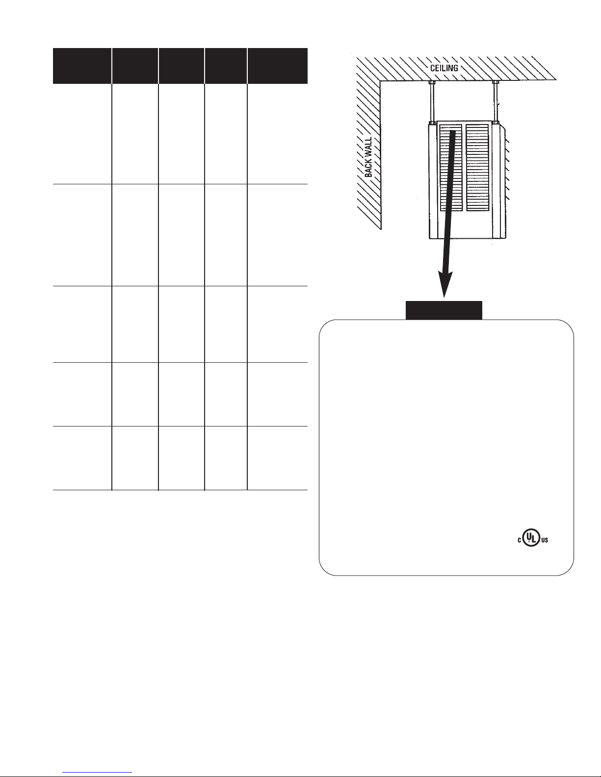
Table 4. Specifications
Mounting
Basic Model Height Width Depth Weight
No. in (mm) in. (mm) in. (mm) lbs. (kg)
HUHAA320 27 (12.2)
HUHAA324 27 (12.2)
HUHAA327 27 (12.2)
HUHAA348 16 14 8-1/2 27 (12.2)
HUHAA520 (406.4) (355.6) (214.4) 27 (12.2)
HUHAA524 27 (12.2)
HUHAA527 27 (12.2)
HUHAA548 30 (13,6)
HUHAA720 38 (17.2)
HUHAA724 38 (17.2)
HUHAA727 38 (17.2)
HUHAA748 21-3/4 19 8-1/2 38 (17.2)
HUHAA1020 (552.5) (482.6) (214.4) 38 (17.2)
HUHAA1024 38 (17.2)
HUHAA1027 38 (17.2)
HUHAA1048 38 (17.2)
HUHAA1520 53 (24.0)
HUHAA1524 53 (24.0)
HUHAA1548 21-3/4 19 13-3/4 53 (24.0)
HUHAA2020 (552.5) (482.6) (346.8) 60 (27.2)
HUHAA2024 60 (27.2)
HUHAA2048 60 (27.2)
HUHAA2524 93 (42.3)
HUHAA2548 30 26-5/8 13-3/4 93 (42.3)
HUHAA3020 (76.2) (676.4) (346.8) 93 (42.3)
HUHAA3024 93 (42.3)
HUHAA3048 93 (42.3)
HUHAA4024 119 (54.0)
HUHAA4048 30 26-5/8 18-1/8 119 (54.0)
HUHAA5020 (76.2) (676.4) (457.2) 119 (54.0)
HUHAA5024 119 (54.0)
HUHAA5048 119 (54.0)
IMPORTANT INFORMATION
NAMEPLATE
MODEL NO.
MFG. NO.
HUHAA324
VOLTS AC KILOWATTS PHASE
60 HZ
208 / 240 2.2 /3 1
MOTOR CONTROL
VAC AMP VAC
208/240 .25 208/240
AIR MINIMUM MOUNTING CLEARANCE
FLOW SIDE BACK CEILING FLOOR
HORIZ. 6" 9.5" 2" 7'
VERT. 18" 18" 6" 7'
WARNING:
DISCONNECT POWER BEFORE SERVICING. IF EXTERNAL CONTROL IS
USED, ALSO DISCONNECT EXTERNAL POWER SUPPLY.
DO NOT TURN LOUVERS ABOVE LEVEL OF THE UNIT.
DATE CODE
0395
774G LISTED
MARLEY ENGINEERED PRODUCTS
BENNETTSVILLE, SC 29512 4104-2088-001
ROOM HEATER
5
Page 6

All products manufactured by Marley Engineered Products are warranted against defects in workmanship and materials for one year from date of installation, except
LIMITED WARRANTY
heating elements which are warranted against defects in workmanship and materials for five years from date of installation. This warranty does not apply to damage from
accident, misuse, or alteration; nor where the connected voltage is more than 5% above the nameplate voltage; nor to equipment improperly installed or wired or
maintained in violation of the product’s installation instructions. All claims for warranty work must be accompanied by proof of the date of installation.
The customer shall be responsible for all costs incurred in the removal or reinstallation of products, including labor costs, and shipping costs incurred to return products
to Marley Engineered Products Service Center. Within the limitations of this warranty, inoperative units should be returned to the nearest Marley authorized service center or the Marley Engineered Products Service Center, and we will repair or replace, at our option, at no charge to you with return freight paid by Marley. It is agreed that
such repair or replacement is the exclusive remedy available from Marley Engineered Products.
THE ABOVE WARRANTIES ARE IN LIEU OF ALL OTHER WARRANTIES EXPRESSED OR IMPLIED, AND ALL IMPLIED WARRANTIES OF MERCHANTABILITY AND
FITNESS FOR A PARTICULAR PURPOSE WHICH EXCEED THE AFORESAID EXPRESSED WARRANTIES ARE HEREBY DISCLAIMED AND EXCLUDED FROM
THIS AGREEMENT. MARLEY ENGINEERED PRODUCTS SHALL NOT BE LIABLE FOR CONSEQUENTIAL DAMAGES ARISING WITH RESPECT TO THE
PRODUCT, WHETHER BASED UPON NEGLIGENCE, TORT, STRICT LIABILITY, OR CONTRACT.
Some states do not allow the exclusion or limitation of incidental or consequential damages, so the above exclusion or limitation may not apply to you. This warranty gives
you specific legal rights, and you may also have other rights which vary from state to state.
For the address of your nearest authorized service center, contact Marley Engineered Products in Bennettsville, SC, at 1-800-642-4328. Merchandise returned to the factory must be accompanied by a return authorization and service identification tag, both available from Marley Engineered Products. When requesting return authorization,
include all catalog numbers shown on the products.
HOW TO OBTAIN WARRANTY SERVICE AND
WARRANTY PARTS PLUS GENERAL INFORMATION
1. Warranty Service or Parts
2. Purchase Replacement Parts
3. General Product Information
Note:
When obtaining service always have the following:
1. Model number of the product
2. Date of manufacture
3. Part number or description
1-800-642-4328
1-800-654-3545
www.marleymep.com
470 Beauty Spot Rd. East
Bennettsville, SC 29512 USA
Part No. 5200-2147-006
ECR 38995
03/11
 Loading...