

Page 1

STANDARD Protocol Manual
English
Rev. 008 - 21/05/2009
1UBMSTD30008
UBN307
DIN 96x96 Compact Power Meter
Universal Berg Netzbaustein
www.berg-energie.de
Page 2

A
ENGLISH
Table of contents
STANDARD Communication Protocol
Table of contents
1. INTRODUCTION 1
2. SYMBOLS 2
3. DESCRIPTION 3
3.1 Communication 3
3.2 Identifi cation code 3
3.3 Data request sequence 4
3.3.1 Response sequence 5
3.4 Parameter setting sequence 6
3.4.1 Response sequence 7
3.5 Check characters 7
4. COMMANDS 8
4.1 Measured values 8
4.2 Programmed parameters & other info 10
4.3 Programmable parameters 12
4.4 Variables list 14
4.5 Error Messages 15
5. ASCII CHARACTERS TABLE 16
Page 3

1
ENGLISH
Introduction
STANDARD Communication Protocol
1. INTRODUCTION
This manual provides information on the STANDARD communication protocol. The publication is
not intended for general use, but for qualifi ed technicians.
This term indicates a professional and skilled technician, authorised to act in accordance with the
safety standards relating to the dangers posed by electric current.
This person must also have basic fi rst-aid training and be in possession of suitable Personal
Protective Equipment.
WARNING!
It is strictly forbidden, for anyone who does not have the above-mentioned
features, to install or use the device.
The device is made in compliance with the European Union directives in force, as well as in compliance with the technical standards implementing these requirements, as certifi ed by the CE mark
on the device and in this manual.
It is strictly forbidden to use the instrument for purposes other than those intended, which can be
deduced from the manual content.
The Manufacturer reserves the right to make changes on the device or in the device specifi cations
identifi ed in this manual without notice.
The Manufacturer declines all liability for any use of the instrument which is different from that
described in this manual and in the instrument manual, or for the lack/incorrect application of the
reported instructions.
The information, contained in this manual, may not be divulged to third parties. Any copy of this
manual, either partial or total, by photocopying, or by other means, also electronically, without
written authorization from the Manufacturer, violates the copyright and is punishable by law.
The information contained in this document is believed to be accurate at the time of publication,
however, the Manufacturer assumes no responsability for any errors which may appear here and
reserves the right to make changes without notice.
Any brands mentioned in the publication are property of their respective owners.
Page 4
2
ENGLISH
Symbols
STANDARD Communication Protocol
2. SYMBOLS
In the manual and on the device, some instructions are highlighted by symbols to draw the reader’s
attention to the operational dangers.
These symbols are the following:
DANGER!
This warning indicates the possible presence of voltage exceeding 1kV
on the marked terminals (even for short periods).
WARNING!
This warning indicates the possible occurrence of an event which may
cause a serious accident or considerable damage to the device if suitable
precautionary countermeasures are not taken.
ATTENTION!
This warning indicates the possible occurrence of an event which may
cause a light accident or damage to the device if suitable precautionary
countermeasures are not taken.
NOTE
This warning indicates important information which must be read carefully.
Page 5
3
Description
ENGLISH
STANDARD Communication Protocol
3. DESCRIPTION
3.1 Communication
The protocol specifi cations defi ne the data sequence, the programming sequence and the check
codes, necessary for a proper data communication.
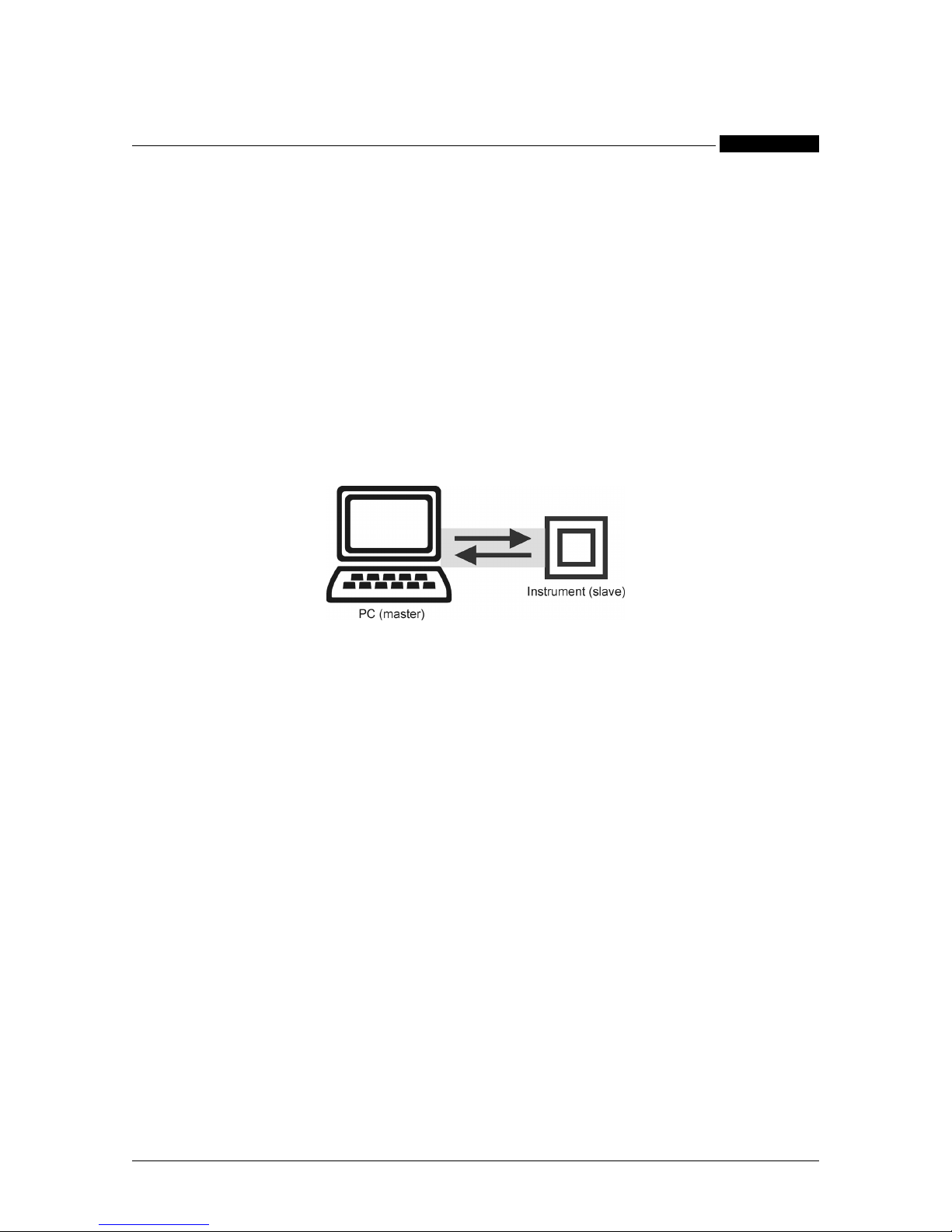
This protocol allows the communication between the PC (master) and the instrument (slave).
The protocol uses an half duplex connection on a single line. In this way, the communication
messages move on a single line in two opposite directions.
It is not possible a communication between instruments, without PC, as they cannot send commands; instruments are limited to reply. All the trasmitted characters are part of the ASCII code (see
chapter 5).
3.2 Identification code
In a multi-point type connection, a code allows to identify each instrument during the communication. This code, the Serial Number, is assigned to each instrument by the manufacturer.
It is made of 9 characters (numbers and letters), printed on the instrument label.
A second identifi cation code, the Logical Number, can be assigned by the user. As it is made up
of 2 ASCII characters ($01...$FF), it allows a faster communication.
The Logical Number can be changed at any time using the specifi c command (see section 4.3).
The instrument is supplied with a $01 Logical Number.
NOTE
The $00 Logical Number is used for broadcast commands. A command with
the $00 Logical number is received by all the instruments connected in the
network.
Page 6

4
Description
ENGLISH
STANDARD Communication Protocol
WARNING
In an instruments network, the $00 code can be used only for sending write
commands. An interrogation would generate a simultaneous response from
all of the instruments, with the possibility of malfunctions.
3.3 Data request sequence
By the master, a data request sequence is sent to the instrument (slave) to read information on
the device (measured values, programmed parameters,...). This interrogation cannot change
instrument confi guration. The following description shows the correct sequence of characters for
a proper interrogation:
<STX>02R63<ETX>($51)
[begin block character]
[instrument identifi cation]
[command]
[end block character]
[check character]
[begin block character]
It is always <STX> ($02) character.
[instrument identifi cation]
It is usually represented by the Logical Number ($01...$FF). The character S ($53) can also be
used followed by the instrument Serial Number (9 alphanumeric characters).
[command]
It is always R ($52) character followed by the variable number to be read (see section 4.1), expressed in hexadecimal.
[end block character]
It is always <ETX> ($03) character.
[check character]
It is a single character which results from EXCLUSIVE OR (XOR) of all the characters from <STX>
up to and including <ETX>. It is used to check the transmitted data.
Page 7

5
Description
ENGLISH
STANDARD Communication Protocol
3.3.1 Response sequence
When the instrument, with the corresponding Serial Number or Logical Number, received a read
command, it replies with the following message.
<STX>+380.0<SP>.....<ETX><BCC>
[begin block character]
[data block]
[end block character]
[check character]
[begin block character]
It is always <STX> ($02) character.
[data block]
The data block format changes according to the sent command.
1. Data block of a variables group.
+380.0<SP>+13.38k...........+123.380k
Algebraic sign
Variable value with decimal point
Multiplier (see the following table)
Character Meaning Multiplier
<SP> space 1
k kilo 1000
M Mega 1000000
G Giga 1000000000
4. Error reply.
Ennn
Error code ($45)
Code relative to the error type
[end block character]
It is always <ETX> ($03) character.
[check character]
It is a single character which results from EXCLUSIVE OR (XOR) of all the characters from <STX>
up to and including <ETX>. It is used to check the transmitted data.
Page 8

6
Description
ENGLISH
STANDARD Communication Protocol
3.4 Parameter setting sequence
By the master, a programming sequence is sent to the instrument (slave) to change specifi c
parameters (instrument confi guration). The following description shows the correct sequence of
characters for a proper command.
<STX>SA1T120050W84=0A<ETX>($67)
[begin block character]
[instrument identifi cation]
[command]
[new value]
[end block character]
[check character]
[begin block character]
It is always <STX> ($02) character.
[instrument identifi cation]
It is usually represented by the Logical Number ($01...$FF). The S ($53) character can also be
used followed by the instrument Serial Number (9 alphanumeric characters).
[command]
It is always W ($57) character followed by the variable number to be changed (see section 4.3)
expressed in hexadecimal by two alphanumeric characters and always followed by the character
=($3D).
[new value]
It is a series of alphanumeric characters which express the new value, according to the assigned
parameter (see section 2.3).
[end block character]
It is always <ETX> ($03) character.
[check character]
It is a single character resulting from EXCLUSIVE OR (XOR) of all the characters from <STX> up
to and including <ETX>. It is used to check the transmitted data.
Page 9

7
Description
ENGLISH
STANDARD Communication Protocol
3.4.1 Response sequence
When the instrument, with the corresponding Serial Number or Logical Number, received a write
command, it replies with the following message.
<STX>E000<ETX>($74)
[begin block character]
[data block]
[end block character]
[check character]
[begin block character]
It is always <STX> ($02) character.
[data block]
It is made up of E ($45) character followed by 3 numerical characters which indicate the code
relative to the error. The E000 code specifi es that the operation has been completed correctly.
[end block character]
It is always <ETX> ($03) character.
[check character]
It is a single character resulting from EXCLUSIVE OR (XOR) of all of the characters from <STX>
up to and including <ETX>, used to check the transmitted data.
3.5 Check characters
The used check characters are the following:
<STX> Start of text ($02)
Start of text character. Preceeds the data in all frames.
<ETX> End of text ($03)
End block character.
<BCC> Block check character
It is represented by 2 digit number, obtained by the operation of EXCLUSIVE OR (XOR) carried
out on the transmitted data, as shown in the preceeding examples.
Page 10

8
Commands
ENGLISH
STANDARD Communication Protocol
4. COMMANDS
NOTE
The * symbol indicates a parameter available only when the instrument
includes the relevant option.
NOTE
NUL indicates a parameter which is not available. In this case, the
instrument sends “-” characters.
4.1 Measured values (codes valid for reading only)
Command Description
R3D.01 ALL MEASURED INSTANTANEOUS VARIABLES
In case of insertion: 3Ph-4W/3CT
Answer format:
<STX>VΣ V1 V2 V3 V12 V23 V31 AΣ A1 A2 A3 THDA1 THDA2 THDA3 AN
PFΣ PF1 PF2 PF3 COSϕ1* COSϕ2* COSϕ3* VAΣ VA1 VA2 VA3 WΣ W1 W2
W3 varΣ var1 var2 var3 +Wh +varhI +varhC +VAh -Wh -varhI -varhC -VAh HCNT
F THDV1 THDV2 THDV3 A1DMD A2DMD A3DMD VAΣDMD WΣDMD AΣDMD
RST T<ETX><BCC>
In case of insertion: 3Ph-3W/3CT
Answer format:
<STX>VΣ NUL NUL NUL V12 V23 V31 AΣ A1 A2 A3 THDA1 THDA2 THDA3 NUL
PFΣ NUL NUL NUL NUL NUL NUL VAΣ NUL NUL NUL WΣ NUL NUL NUL varΣ NUL
NUL NUL +Wh +varhI +varhC +VAh -Wh -varhI -varhC -VAh NUL F NUL NUL NUL
A1DMD A2DMD A3DMD VAΣDMD WΣDMD AΣDMD RST T<ETX><BCC>
Value formats:
Instantaneous values•
sign (space, +, -) + value on 4 digits with decimal point (5 char) + multiplier (space,
k, M, G, T, …)
Energy counters and Digital Inputs*•
sign (+, -) + value on 8 digits with decimal point (9 char) + multiplier (k, M, G, T, …)
Phase sequence•
sign (space) + value on 3 digits with decimal point (4 char) + multiplier (space)
Page 11

9
Commands
ENGLISH
STANDARD Communication Protocol
R3D UPM 300A (NEW VERSION) COMPATIBLE ANSWER FORMAT
In case of insertion:3Ph-4W/3CT
Answer format:
<STX> VΣ V1 V2 V3 V12 V23 V31 AΣ A1 A2 A3 PFΣ PF1 PF2 PF3 VAΣ VA1 VA2
VA3 WΣ W1 W2 W3 varΣ var1 var2 var3 +Wh +varhI F WΣDMD AΣDMD RST
T<ETX><BCC>
In case of insertion:3Ph-3W/3CT
Answer format:
<STX> VΣ NUL NUL NUL V12 V23 V31 AΣ A1 A2 A3 PFΣ NUL NUL NUL VAΣ NUL
NUL NUL WΣ NUL NUL NUL varΣ NUL NUL NUL +Wh +varhI F WΣDMD AΣDMD
RST T<ETX><BCC>
Value format: see R3D.01
R3E UPM 300 (OLD VERSION) COMPATIBLE ANSWER FORMAT
In case of insertion: 3Ph-4W/3CT
Answer format:
<STX> VΣ V1 V2 V3 V12 V23 V31 AΣ A1 A2 A3 PFΣ PF1 PF2 PF3 VAΣ VA1 VA2 VA3 WΣ
W1 W2 W3 varΣ var1 var2 var3 +Wh +varhI F WΣDMD AΣDMD <ETX><BCC>
In case of insertion: 3Ph-3W/3CT
Answer format:
<STX> VΣ NUL NUL NUL V12 V23 V31 AΣ A1 A2 A3 PFΣ NUL NUL NUL VAΣ
NUL NUL NUL WΣ NUL NUL NUL varΣ NUL NUL NUL +Wh +varhI NUL WΣDMD
NUL<ETX> <BCC>
Value format: see R3D.01
R3E.01 CURRENT DEMAND VALUES
Answer format:
<STX> A1DMD A2DMD A3DMD VAΣDMD WΣDMD AΣDMD<ETX> <BCC>
R60 ALL MAXIMUM VALUES
Answer format:
<STX>V1 V2 V3 V12 V23 V31 A1 A2 A3 AN A1DMD A2DMD A3DMD WΣDMD
VAΣDMD<ETX><BCC>
R76.01 PHASE1 VOLTAGE SAMPLES
Answer format:
<STX> 512 characters (128 samples per 1 wave)<ETX><BCC>
R76.02 PHASE2 VOLTAGE SAMPLES
Answer format:
<STX> 512 characters (128 samples per 1 wave)<ETX> <BCC>
Command Description
Page 12

10
Commands
ENGLISH
STANDARD Communication Protocol
R76.03 PHASE3 VOLTAGE SAMPLES
Answer format:
<STX> 512 characters (128 samples per 1 wave)<ETX> <BCC>
R77.01 PHASE1 CURRENT SAMPLES
Answer format:
<STX> 512 characters (128 samples per 1 wave)<ETX> <BCC>
R77.02 PHASE2 CURRENT SAMPLES
Answer format:
<STX> 512 characters (128 samples per 1 wave)<ETX> <BCC>
R77.03 PHASE3 CURRENT SAMPLES
Answer format:
<STX> 512 characters (128 samples per 1 wave)<ETX> <BCC>
R79 PHASE1 VOLTAGE HARMONICS INSTANT VALUES*
Answer format:
<STX> 80 characters(16 harmonics x 5 char.)<ETX><BCC>
R7A PHASE2 VOLTAGE HARMONICS INSTANT VALUES*
Answer format:
<STX> 80 characters(16 harmonics x 5 char.)<ETX><BCC>
R7B PHASE3 VOLTAGE HARMONICS INSTANT VALUES*
Answer format:
<STX> 80 characters(16 harmonics x 5 char.)<ETX><BCC>
R7C PHASE1 CURRENT HARMONICS INSTANT VALUES*
Answer format:
<STX> 80 characters(16 harmonics x 5 char.)<ETX><BCC>
R7D PHASE2 CURRENT HARMONICS INSTANT VALUES*
Answer format:
<STX> 80 characters(16 harmonics x 5 char.)<ETX><BCC>
R7E PHASE3 CURRENT HARMONICS INSTANT VALUES*
Answer format:
<STX> 80 characters(16 harmonics x 5 char.)<ETX><BCC>
Command Description
Page 13

11
Commands
ENGLISH
STANDARD Communication Protocol
4.2 Programmed parameters & other info
R5F ALL PROGRAMMED PARAMETERS OF THE INSTRUMENT
Answer format:
<STX> W80; W84; W90; W92; W98; W9B; WDA; WDB; WDE; WA(0/1); WB(0/1)
<ETX><BCC>
R63 SERIAL NUMBER
R78 INSTRUMENT FIRMWARE VERSION
R7F.001 INSTRUMENT CONFIGURATION
Answer format:
<STX>OA=00;OD=02;ID=00;RAM=0000;HILO=00;C=43561;O=PT;C;HAR<ETX><BCC>
OA - Reserved
OD - Number of digital outputs
ID - Number of digital inputs*
RAM - Reserved
HILO - Tariff: 00=not provided, 01=provided
C - Wiring modes: 1=1ph, 3=3.3.3, 4=3.4.3, 5=3.3.1, 6=3.2.1
O - DO’s output mode: PT=pulse and threshold
C - Provided with temperature indication: C=in Celsius degree, F=in Fahrenheit degree
HAR - Provided with harmonics
R7F.002 FULL SCALE INFORMATION
Answer format:
<STX>KTA=0001;KTV=0001;FSA=5;FSV=0433;FSV3=0750;FSW=2165;CSDO=1
320<ETX><BCC>
KTA - CT Value
KTV - PT Value
FSA - Current full scale
FSV - Voltage full scale
FSV3 - System voltage full scale
FSW - Power full scale
CSDO - Reserved
R7F.004 INSTRUMENT NAME
Command Description
Page 14

12
Commands
ENGLISH
STANDARD Communication Protocol
4.3 Programmable parameters (codes valid for writing only)
W80 SERIAL COMMUNICATION
Format: W80=Baud Rate,Parity,Data Bit,Stop
Baud Rate 300, 600, 1200, 2400, 4800, 9600, 19200, 38400, 57600
Parity None, Even, Odd
Data Bits 8
Stop 1
Example: W80=38400,N,8,1
W84 LOGICAL NUMBER
Format: W84=XX
Available values: $01÷$FF
Example: W84=01
W90 CT RATIO
Format: W90=XXXX
Available values: 0001÷9999
Example: W90=0001
W92 PT RATIO
Format: W92=XXXX
Available values: 0001÷9999
Example: W92=0001
WDA WIRING MODE
Format: WDA=XX
Available values: 01=1phase
03=3phases-3wires / 3CTs
04=3phases-4wires / 3CTs
05=3phases-3wires / 1CT
06=3phases-2wires / 1CT
Example: WDA=04
WDB CURRENT FULL SCALE
Format: WDB=XX
Available values: 01=1A
05=5A
Example: WDB=01
W98 INTEGRATION TIME FOR DEMAND VALUES CALCULATION
Format: W98=XX
Available values: 01, 05, 10, 15, 30, 60 minutes
Example: W98=01
Command Description
Page 15

13
Commands
ENGLISH
STANDARD Communication Protocol
W9B LCD BACKLIGHTING ON TIME
Format: W9B=XXX
Available values: 000÷999 seconds
Example: W9B=060
W9F CLEAR COUNTERS
Format: W9F=XXXXX
Available values: 43000=clear energy counters
24000=clear hourscounter*
Example: W9F=43000
WCE CLEAR ALL PEAK AND DEMAND PEAK VALUES
Format: WCE=XX
Available values: 00 fi xed
Example: WCE=00
WDE LANGUAGE
Format: WDE=XX
Available values: 00=English
01=Deutsch
02=Italiano
Example: WDE=00
DIGITAL OUTPUT 1
WA0 PULSE
Format: WA0=XX,Y.YYY,ZZZ
XX associated energy variable (see section 4.4)
Y.YYY pulse coeffi cient (ex. Wh/pulse)
ZZZ pulse length time - 150 msec. fi xed
Example: WA0=30,0.125,150
WA1 THRESHOLD
Format: WA1=XX,Y,ZZZ.ZZ,JJ,KKK
XX associated variable - no energy variables (see section 4.4)
Y threshold mode
L=low threshold mode
H=high threshold mode
ZZZ.ZZ tripping value (%) referring to the full scale
JJ hysteresis percentage value referring to the tripping value
KKK delay time on threshold tripping - available values: 0.03, 0.3, 1, 3, 10,
30, 100 sec.
Example: WA1=20,H,050.00,15,010
DIGITAL OUTPUT 2
WB0 PULSE (see WA0)
WB1 THRESHOLD (see WA1)
Command Description
Page 16

14
Commands
ENGLISH
STANDARD Communication Protocol
4.4 Variables list
The code assigned to each variable is described in the following list.
N. var. Description Symbol
00 System voltage VΣ
01 L-N voltage phase 1 V1
02 L-N voltage phase 2 V2
03 L-N voltage phase 3 V3
04 L-L voltage 12 V12
05 L-L voltage 23 V23
06 L-L voltage 31 V31
08 System current AΣ
09 Phase 1 current A1
0A Phase 2 current A2
0B Phase 3 current A3
0F Neutral current AN
36 Phase 1 voltage THD THDV1
37 Phase 2 voltage THD THDV2
38 Phase 3 voltage THD THDV3
0C Phase 1 current THD THDA1
0D Phase 2 current THD THDA2
0E Phase 3 current THD THDA3
34 Frequency F
3B Phase order RST
10 System power factor PFΣ
11 Phase 1 power factor PF1
12 Phase 2 power factor PF2
13 Phase 3 power factor PF3
15 Phase 1 COSϕ COSϕ1
16 Phase 2 COSϕ COSϕ2
17 Phase 3 COSϕ COSϕ3
18 System apparent power VAΣ
19 Phase 1 apparent power VA1
1A Phase 2 apparent power VA2
1B Phase 3 apparent power VA3
20 System active power WΣ
21 Phase 1 active power W1
22 Phase 2 active power W2
23 Phase 3 active power W3
28 System reactive power varΣ
29 Phase 1 reactive power var1
2A Phase 2 reactive power var2
2B Phase 3 reactive power var3
39 System active power demand WΣDMD
35 System apparent power demand VAΣDMD
Page 17

15
Commands
ENGLISH
STANDARD Communication Protocol
52 Phase 1 current demand A1DMD
53 Phase 2 current demand A2DMD
54 Phase 3 current demand A3DMD
3A System current demand AΣDMD
FE None variable selected
30 Imported active energy +Wh
1C Imported apparent energy +VAh
31 Imported reactive lagging energy +varhI
33 Imported reactive leading energy +varhC
32 Exported active energy -Wh
1D Exported apparent energy -VAh
2E Exported reactive lagging energy -varhI
2F Exported reactive leading energy -varhC
4.5 Error messages
Nr Description
E000 COMMAND ACKNOWLEDGE (NO ERROR)
Reception of a correct command.
SCONOSCIUTO No Si
E001 COMMAND ERROR
Reception of an incorrect command.
NOTE
A verifi cation error on BCC is not indicated, the reception of a complete message, but with incorrect BCC is completely ignored by the instrument.
N. var. Description Symbol
Page 18
16
ASCII characters table
ENGLISH
STANDARD Communication Protocol
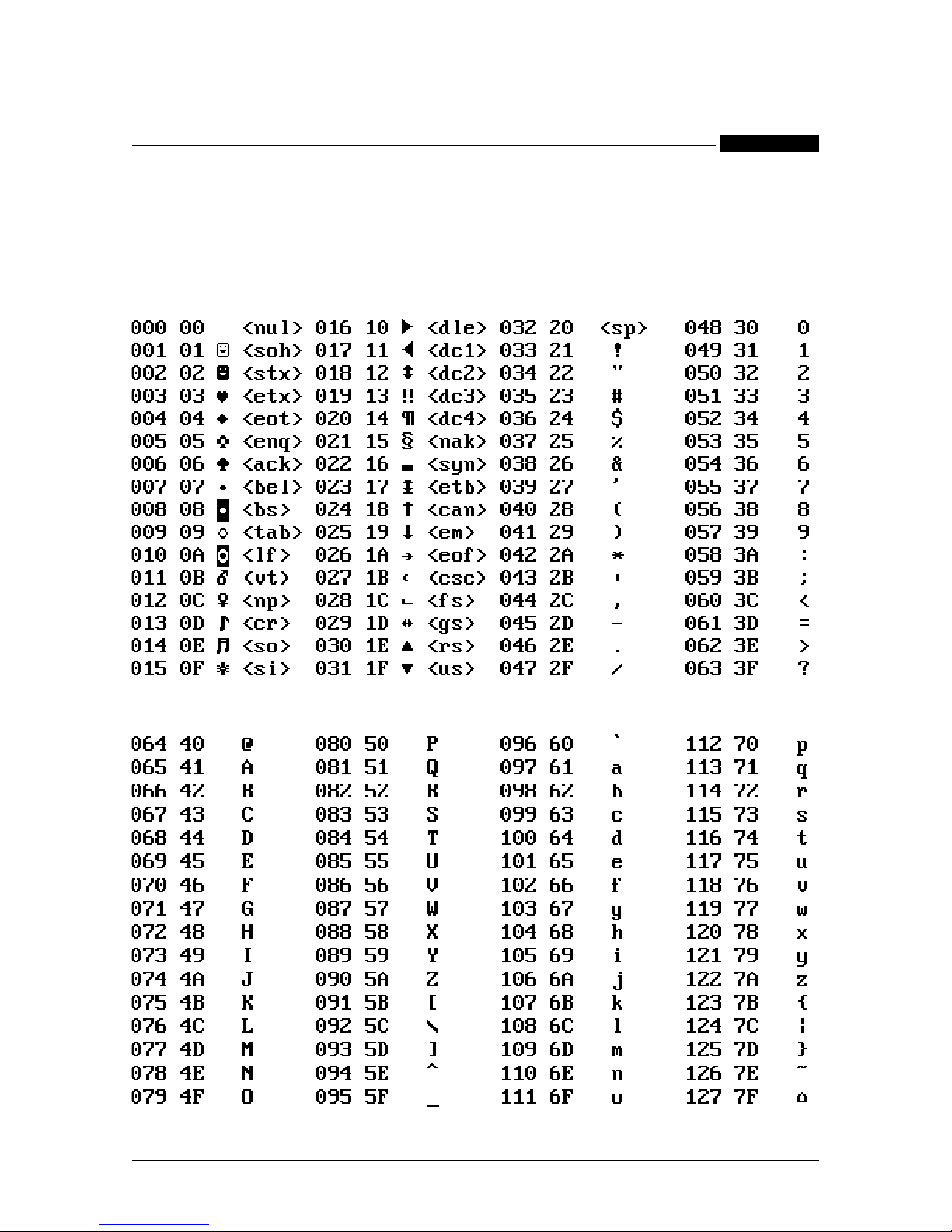
5. ASCII CHARACTERS TABLE
DEC HEX CHAR. DEC HEX CHAR. DEC HEX CHAR. DEC HEX CHAR.
DEC HEX CHAR. DEC HEX CHAR. DEC HEX CHAR. DEC HEX CHAR.
Page 19

17
ASCII characters table
ENGLISH
STANDARD Communication Protocol
DEC HEX CHAR. DEC HEX CHAR. DEC HEX CHAR. DEC HEX CHAR.
DEC HEX CHAR. DEC HEX CHAR. DEC HEX CHAR. DEC HEX CHAR.
Page 20

18
ASCII characters table
ENGLISH
STANDARD Communication Protocol
NOTES:
Page 21

19
ASCII characters table
ENGLISH
STANDARD Communication Protocol
NOTES:
Page 22

20
ASCII characters table
ENGLISH
STANDARD Communication Protocol
NOTES:
Page 23

Energieservice - Optimierungssysteme - Betriebsdatenerfassung
Fraunhofer Straße 22 - D - 82152 Martinsried - Telefon +49 (0)89 379160 - 0 / Telefax +49 (0)89 379160 - 199
http: // www.berg-energie.de - E mail: [email protected]
 Loading...