

Page 1
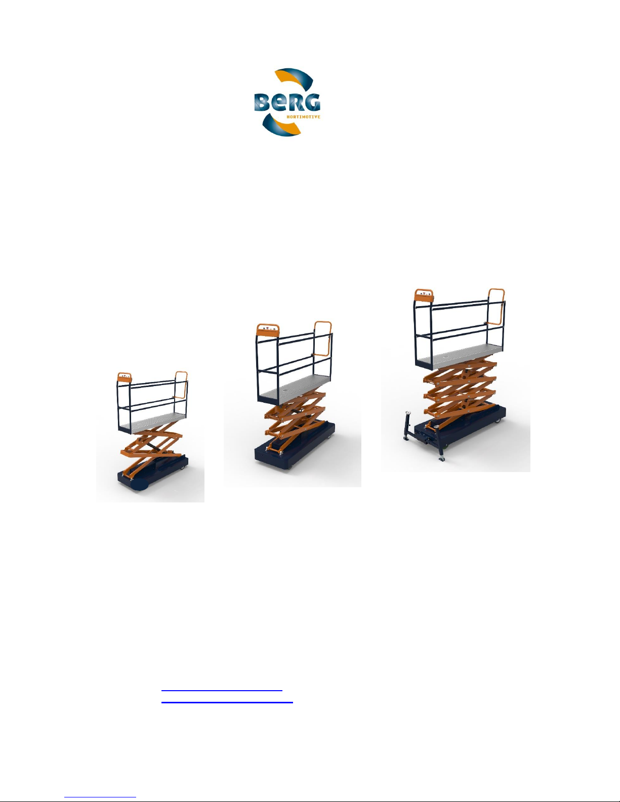
Technical Handbook
BENOMIC
Berg Hortimotive
Burg. Crezeelaan 42a
2678 KZ De Lier
Nederland
Tel: +31 (0) 174- 517 700
Fax: +31 (0) 174- 516 958
Page 2
Translated user manual (EN-V11) BENOMIC 2 / 43
Machine type plate
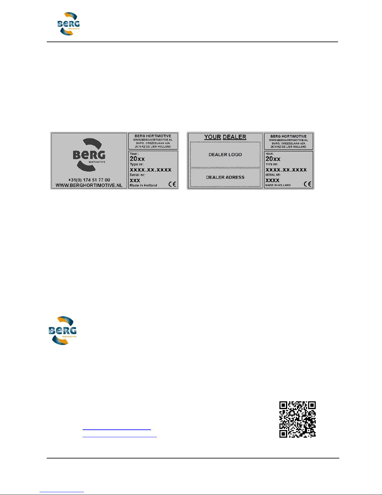
The BENOMIC is fitted with a machine type plate which contains the following information:
address details for Berg Hortimotive, CE mark, serial and type reference, serial number, year of
construction.
If you would like to contact Berg Hortimotive, or one of their dealers with respect to this
BENOMIC, please ensure that this information is always readily available.
Version 11, April 2019
The machine is manufactured by:
Berg Hortimotive
Burg. Crezeelaan 42a
2678 KZ De Lier
Nederland
Tel: +31 (0) 174- 517 700
Fax: +31 (0) 174- 516 958
Page 3

Translated user manual (EN-V11) BENOMIC 3 / 43
1. Declaration
1.1 Copyright
Berg Hortimotive
De Lier, 2019
No part of this publication may be reproduced and/or published by way of print, photocopy, film
or by any other means without the prior written consent of Berg Hortimotive, registered at De
Lier, the Netherlands.
Exceptions to this include parts of the documentation which are intended for reproduction, such
as abridged instructions and specifications on the machine itself.
1.2 Liability
Berg Hortimotive does not accept liability for dangerous situations, accidents and damage that
occur as a result of ignoring warnings or instructions, such as those shown on the BENOMIC, or
contained in this documentation - for example:
- inexperienced or incorrect usage or maintenance
- being used for applications other than those for which it was designed, or in
circumstances other than those given in this documentation
- the use of components or spare parts which are not prescribed
- repairs carried without the consent of Berg Hortimotive and/or a certified dealer
- changes to the BENOMIC include the following:
- alterations to the controls
- welding, mechanical works, etc
- extensions to the BENOMIC or its controls
Berg Hortimotive does not accept liability when:
- customers do not meet their obligations with respect to Berg Hortimotive (financial or
otherwise)
- consequential damage is caused by defects on the BENOMIC - e.g. interruption of
business, delays, etc.
Page 4

Translated user manual (EN-V11) BENOMIC 4 / 43
1.3 Guarantee
For a period of 6 months after delivery, Berg Hortimotive gives the client a warranty on material
and manufacturing defects that occur during normal use. This warranty does not apply if the
defects are caused by improper use or causes other than by material and manufacture, if Berg
Hortimotive - following consultation with the client - delivers used material or used goods or if
the cause of the defects cannot be demonstrated clearly.
The warranty provisions are set out in the METAALUNIE CONDITIONS as they read according
to the most recent relevant text. The terms and conditions of delivery are available on request.
The warranty given by Berg Hortimotive for all goods and materials not manufactured by Berg
Hortimotive will never be more than that given by its supplier. The warranty is ex works. Faulty
machines and/or parts must be sent postage paid.
When it is not possible to send out machines or systems, any travel and subsistence expenses
will be payable by the client.
Sold and delivered goods with manufacturer's, importer's or wholesaler's warranties are subject
only to the warranty provisions set by the suppliers.
Hydraulic pumps are subject only to the manufacturer's warranty, provided the pump comes
with an undamaged safety seal from the supplier.
Berg Hortimotive accepts responsibility for the availability of replacement parts, provided they
are available from its suppliers at reasonable conditions.
2. Foreword
This handbook describes the BENOMIC.
This handbook provides you with information including the safety aspects, a description of the
BENOMIC together with the working principles, as well as the operating instructions and
maintenance of the machine.
Potentially dangerous situations are indicated together with recommendations for avoiding
them.
It is important that this handbook is carefully read in order to learn how the BENOMIC should be
operated and maintained. By reading this handbook and then using the BENOMIC, you, or
anyone else, will be assisted in using the BENOMIC in the correct manner thereby helping to
avoid personal injury as well as damage to the machine.
Berg Hortimotive produces safe machines. The machines are designed to meet the latest
standards and are manufactured in accordance with the latest CE approval markings. The user
remains responsible for the proper operation and for carrying out maintenance on the machine.
Page 5

Translated user manual (EN-V11) BENOMIC 5 / 43
Table of Contents
1. DECLARATION ................................................................................................................................................... 3
1.1 COPYRIGHT ................................................................................................................................................... 3
1.2 LIABILITY ....................................................................................................................................................... 3
1.3 GUARANTEE ................................................................................................................................................... 4
2. FOREWORD ........................................................................................................................................................ 4
3. INTRODUCTION .................................................................................................................................................. 6
3.1 GENERAL ....................................................................................................................................................... 6
3.2 SUPPLIERS INFORMATION ................................................................................................................................ 6
4. SAFETY ............................................................................................................................................................... 7
4.1 EXPLANATION OF SAFETY TERMINOLOGY ........................................................................................................... 7
4.2 SAFETY INSTRUCTIONS ................................................................................................................................... 7
4.3 SAFETY SYMBOLS ......................................................................................................................................... 10
4.4 OTHER RISKS ............................................................................................................................................... 10
5. APPLICATION ................................................................................................................................................... 11
5.1 SCOPE ........................................................................................................................................................ 11
5.2 DESCRIPTION OF THE BENOMIC ................................................................................................................... 11
6. TRANSPORT ..................................................................................................................................................... 16
6.1 EXTERNAL TRANSPORT ................................................................................................................................. 16
6.2 INTERNAL TRANSPORT ................................................................................................................................... 16
7. PUTTING INTO OPERATION ............................................................................................................................ 17
7.1 INSPECTION PRIOR TO PUTTING INTO OPERATION .............................................................................................. 17
7.2 HORTICULTURE SECTOR GUIDELINES FOR PIPE RAIL SYSTEMS ............................................................................ 17
7.3 MINIMUM REQUIREMENTS FOR A PIPE RAIL SYSTEM ........................................................................................... 18
7.4 ALIGNMENT WARNINGS SYSTEM ...................................................................................................................... 19
7.5 STABILIZERS ................................................................................................................................................ 19
8. USAGE ............................................................................................................................................................... 20
8.1 OPERATION .................................................................................................................................................. 21
8.1.1 Controls located on the lower trolley ................................................................................................. 21
8.1.2 Controls located on the platform ....................................................................................................... 22
8.2 EMERGENCY LOWERING VALVE....................................................................................................................... 24
8.3 MOVING THE BENOMIC ON THE MAIN PATHWAY ............................................................................................. 24
8.4 OUT OF USE ................................................................................................................................................. 24
8.5 CLEANING .................................................................................................................................................... 25
8.6 HARVEST CONTAINER .................................................................................................................................... 25
8.7 PROBLEMS, CAUSES AND SOLUTIONS .............................................................................................................. 25
8.8 DISPOSAL .................................................................................................................................................... 27
9. REPAIRS & MAINTENANCE............................................................................................................................. 27
9.1 SPECIALIST MAINTENANCE ............................................................................................................................. 28
9.2 MAINTENANCE IN AND AROUND THE SCISSOR ASSEMBLY ................................................................................... 28
9.3 PIPE RAIL SYSTEM MAINTENANCE .................................................................................................................... 28
9.4 INSPECTION CARBON BRUSHES....................................................................................................................... 29
9.5 TENSIONING THE CHAIN ................................................................................................................................. 29
9.6 CHARGING THE BATTERIES ............................................................................................................................ 30
10. TECHNICAL SPECIFICATIONS ................................................................................................................... 31
11. EC DECLARATION OF CONFORMITY ........................................................................................................ 33
APPENDIX 1: MAINTENANCE LOG BOOK ...................................................................................................... 34
APPENDIX 2: OPERATION OF THE STABILIZERS ......................................................................................... 35
APPENDIX 3: SAFETY DATA SHEET BATTERY ............................................................................................. 38
APPENDIX 4: CLEANING THE POWDER COATING ....................................................................................... 43
Page 6

Translated user manual (EN-V11) BENOMIC 6 / 43
3. Introduction
3.1 General
You have made a good choice by purchasing the Berg Hortimotive BENOMIC. You are the
owner of an first class piece of equipment that has been manufactured with great care. You will
gain the most advantage from the equipment provided that you carefully follow the instructions
given in this handbook with regard to safety, operating and maintenance.
Please study this user's handbook carefully before starting to use the BENOMIC. Always follow
the safety instructions and recommendations given in this handbook.
Berg Hortimotive does not accept liability for damage or indirect damage resulting from not
following the operating and safety instructions contained in this handbook.
Neither does Berg Hortimotive accept liability whenever you or a third party make modifications
to the pipe rail wagon or its accessories, without receiving prior written permission from the
manufacturer.
The BENOMIC is supplied in accordance with the conditions of sale of the Dutch METAALUNIE,
as determined by the registrar of the law court of Rotterdam and in accordance with the most
recent text contained therein. A copy of the terms and conditions of supply can be provided on
request. You can also contact the Koninklijke Metaalunie, PO Box 2600, 3430 GA Nieuwegein,
the Netherlands.
3.2 Suppliers information
In the event of breakdowns or defects occurring on the BENOMIC please contact your Berg
Hortimotive dealer.
Page 7

Translated user manual (EN-V11) BENOMIC 7 / 43
4. Safety
4.1 Explanation of safety terminology
Safety terminology
Danger : Indicates serious or even fatal injury may occur if the instructions in the
handbook are ignored.
Warning : Indicates injury if the instructions described in this handbook
are ignored.
Caution : Indicates damage may occur to the equipment if the instructions
described in this handbook are ignored.
Warning : Indicates possible problems if the instructions described in this
handbook are ignored.
4.2 Safety Instructions
Read the following safety instructions carefully.
After reading the safety instructions they should be closely followed at all times.
The dangers attached to operating the Pipe Rail Trolley will be greatly increased if the safety
instructions are not closely followed at all times, thereby resulting in the possibility of injury.
DANGER!
- Read the user's manual thoroughly. Keep to the operating and safety instructions at all
times.
- The BENOMIC is suitable for operating on a pipe rail system that complies with the
horticulture sector guidelines, the health and safety catalog in force in the Netherlands
(see 7.2).
- Only operate the BENOMIC on the correct pipe rail system. Ensure that the centre to
centre measurement of the pipe rails matches precisely with that of the pipe rail trolley see pictogram on the platform.
- Never exceed the maximum loading capacity of 250kg with a standard double scissor
model or 450/550kg with the heavy duty double scissor model or 120kg with a 3-4 scissor
model.
- 1 person including load (e.g. harvest container or appliances); see pictogram on platform.
- Never exceed lateral (sideways) manual force of 110N (11kg traction).
- It is forbidden to carry out maintenance activities using the BENOMIC
- The BENOMIC may only be used for harvesting and tending the plants in the greenhouse.
- It is forbidden to use the BENOMIC with an alignment variation exceeding 2 (lengthwise
and/or breadth).
- All loads should be secured and placed in the centre of the work platform.
- It is forbidden to carry more than one (1) person on the platform at the same time.
- It is forbidden to allow people to ride on the trolley chassis.
- It is forbidden to remove the safety rail, unless a container fitted with a rail is in use.
- It is strictly forbidden to increase the lift height by any means whatsoever.
- Always remain standing on the work platform
Page 8

Translated user manual (EN-V11) BENOMIC 8 / 43
- Keep a safe distance from fixed and/or moving parts within the greenhouse as well as
cables and ropes.
- It is forbidden to pull (steel) cables or lay screens using the BENOMIC.
- It is forbidden to use the BENOMIC as a crane or hoist.
- It is forbidden for people or pets to enter the track area in which the BENOMIC is in
operation. Never operate more than one pipe trolley in the same track!
- While in operation all safety caps and protective covers on the BENOMIC must be fitted
and fixed down.
- All optional equipment, fittings and spare parts must be manufactured and/or supplied by
Berg Hortimotive
- Harvest containers with sliding racks must be installed in the correct position on the work
platform (see 6.6). The container may overhang the sliding rack up to a maximum of
500mm on both the front and rear sides of the BENOMIC.
- Harvest containers should only be filled with lightweight produce such as peppers and up
to a maximum weight of 250kg. It is forbidden to use containers on the 3-4 scissor model!
Warning!
- Operating the BENOMIC should only take place provided that there is nobody in the
vicinity (except the operator) or standing within a short distance.
- The BENOMIC may only be operated by persons of at least 18 years of age who have
received adequate instructions for operating the BENOMIC and have thoroughly read and
understood the contents of this manual and are fully aware of the associated dangers.
- The BENOMIC may only be operated once it has been correctly installed on the pipe rail
system.
- All personnel working in the area of the BENOMIC should be made familiar with the
relevant safety rules and precautions that apply to pipe rail trolley system.
- Instructions from the employer.
- Repairs to the BENOMIC may only be carried out by staff specially trained by Berg
Hortimotive.
- During maintenance activities on the scissors they should always be supported using the
scissor wedges (see 9.2).
- Never carry out activities on the BENOMIC while it is being operated by another person.
Always disconnect the BENOMIC at the main switch and disconnect the charging plug
from the trolley before starting maintenance activities.
- Check the BENOMIC daily for defects and carry out maintenance on a regular basis - see
chapter 9, maintenance.
- Keep the controls and safety symbols clean at all times.
- operating controls and safety pictograms should always be visible.
- The BENOMIC must always be disconnected at the main switch after use.
Page 9

Translated user manual (EN-V11) BENOMIC 9 / 43
- Never leave the BENOMIC unattended.
- Unless the key has been removed from the main switch.
- It is forbidden to carry out modifications/alterations to the BENOMIC without receiving
prior written consent from Berg Hortimotive
- Before travelling along the pipe rail track always check that there are no persons in the
immediate vicinity.
- It is forbidden to transport loose cargo with the BENOMIC.
- Stack the loads in such a way that they reach no higher than 40cm above the work
platform. All loads should be properly secured.
- Before using a track, ensure that it is clear of obstacles such as plant remains etc.
- Never clean the BENOMIC using a water hose, high pressure spray or steam equipment.
- Other than when on the pipe rails, the scissor should be fully collapsed before moving the
BENOMIC.
- Never use the BENOMIC on public roads or paths.
- It is forbidden to step off the equipment before it is in the lowest position.
- Follow the safety instructions for the batteries - see Appendix 3.
- Think about your feet and toes when operating the lift on the BENOMIC! The trolley is
positioned a few centimetres in front when setting down!
- It is mandatory to wear footwear with steel toe caps (S1).
- Remove the charging plug before operating the BENOMIC.
- After use, the direction of travel switch should always be set at neutral.
Attention!
- Always keep the working area tidy.
- An untidy working area can lead to dangerous situations.
- Always concentrate on the task in hand.
- Remain alert at all times when operating the Pipe Rail Trolley. Do not use the BENOMIC if you re
unable to concentrate or are taking medicine that advises against operating machines or driving a
motor vehicle.
Page 10
Translated user manual (EN-V11) BENOMIC 10 / 43
4.3 Safety symbols
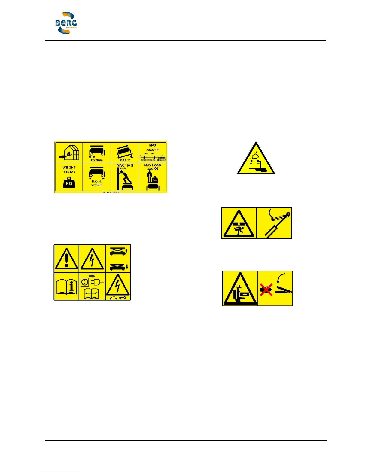
A number of safety symbols are located on the BENOMIC for your information. The symbols are
designed to warn the operator of possible dangers and also dangerous situations. Always take
heed of the warnings and if in doubt about the meaning of a particular symbol, please contact
your supplier for further explanation.
Ensure that the symbols are always clearly visible and remain undamaged!
The BENOMIC operator must thoroughly read and understand the contents of this manual. If
the operator does not understand the warnings given on the equipment or in this manual (e.g.
they speak another language), then all the instructions, possible dangers, warnings and
functions must be fully explained to them by a responsible person so that they are fully
understood.
4.4 Other risks
Dangers can still arise despite the careful design and the use of safety devices, as well as
warnings against possible dangers placed on the machine itself and printed in the manual. Pay
attention to the following:
- The danger of fingers, hands, arms and head becoming wedged between the scissors!
- The danger of becoming wedged under the trolley during lowering or raising with a hoist!
- The trolley tipping over resulting from an unsuitable pipe rail system!
- The trolley tipping over resulting from exceeding the maximum load or manual force!
Suitable for the stated pipe diameter with a minimum wall thickness
Suitable for the stated centre to centre size of the pipe rail system
Maximum lateral (sideways) manual force in Newtons (kg x 10)
maximum total load in kg (maximum 1 person + load)
Maximum alignment variation 2°
Maximum support distance 1250mm
Use only indoors (in the greenhouse)
The figures depend on the type of BENOMIC!
Attention! Read the manual before operating!
Attention! Disconnect the power supply and consult the manual before
carrying out maintenance
Raise = scissor up, lower = scissor down
Main power switch: key vertical= ON, key horizontal = OFF
The Key is to be turned beyond the OFF position in order to extract it.
Attention: Dangerous
chemical battery - danger
of gas explosion and
corrosive battery acid
Watch out when the platform
descends!
Always use the scissor wedges
when working underneath or on the
scissors!
Attention - Danger of getting
trapped!
Keep your hands clear of the
scissors!
Page 11
Translated user manual (EN-V11) BENOMIC 11 / 43
5. Application
5.1 Scope
The BENOMIC has been designed for professional use in greenhouses in the horticultural
sector.
Operation may only be carried out by one person with a minimum age of 18 years who has
received adequate instruction with regard to the BENOMIC and who has received a copy of the
written (safety) instructions and has read and fully understood the contents of this manual.
The BENOMIC is a pipe rail trolley that travels along a pipe rail system constructed in
accordance with the sector guidelines, -the health and safety catalog in force in the Netherlands
- it is designed as an aid for harvesting crops (only the double scissor) and tending and/or
maintaining plants growing in a greenhouse. It is forbidden to use the BENOMIC for any other
purposes. The loading may only consist of a maximum of one person with a secured load which
together weight no more than 250kg for the standard 2-scissor model, 450/550kg for the heavy
duty 2-scissor model and a maximum of 120kg for the 3-scissor model. The trolley may only be
manned once it has been correctly installed on the pipe rail system. Be fully alert when the
scissor is lowering thereby ensuring that no persons or objects can become wedged under or
between the scissor assembly. The platform must not be entered while on a concrete pathway.
Always walk alongside the trolley and never sit or stand on the chassis when travelling on the
main pathways.
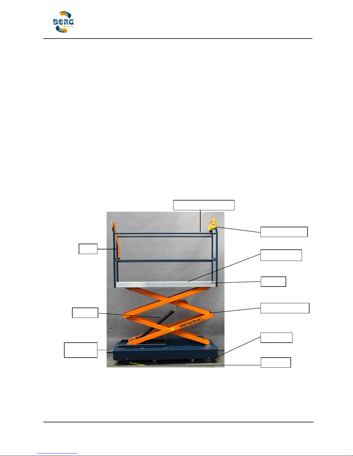
5.2 Description of the BENOMIC
Fencing/safety rails
Control panel
Foot pedal (5)
Platform
Scissor construction
Door
Drive
Runner
Cylinder
Lower trolley
controls
Fig. 3.1 - Names of the parts on the upper construction of the BENOMIC
Page 12
Translated user manual (EN-V11) BENOMIC 12 / 43
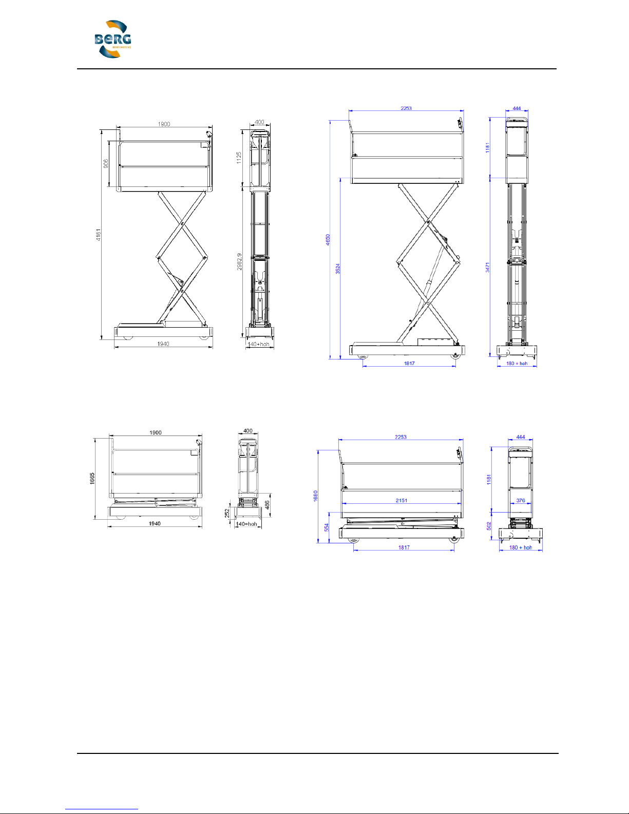
Fig. 3.2 - Maximum dimensions of the 2-scissor up to 3 meter
Fig. 3.3 - Minimum dimensions of the 2-scissor up to 3 meter
Fig. 3.4 - Maximum dimensions of the 2-scissor up to 3.5 meter
Fig. 3.5 - Minimum dimensions of the 2-scissor up to 3.5 meter
Page 13
Translated user manual (EN-V11) BENOMIC 13 / 43
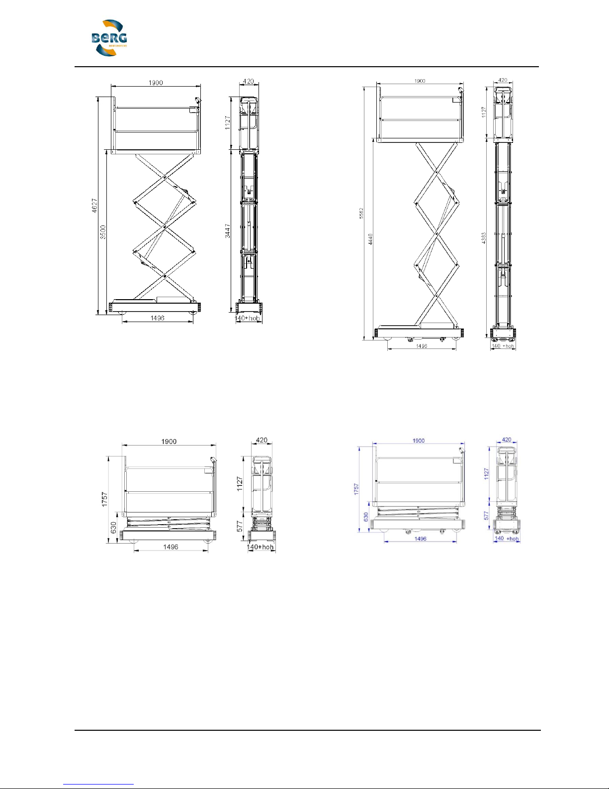
Fig. 3.6 - Maximum dimensions of the 3-scissor model up to 3.5m
Fig. 3.8 - Maximum dimensions of the 3-scissor model up to 4.4m
Fig. 3.7 - Minimum dimensions of the 3-scissor model up to 3.5m
Fig. 3.9 - Minimum dimensions of the 3-scissor model up to 4.4m
Page 14
Translated user manual (EN-V11) BENOMIC 14 / 43
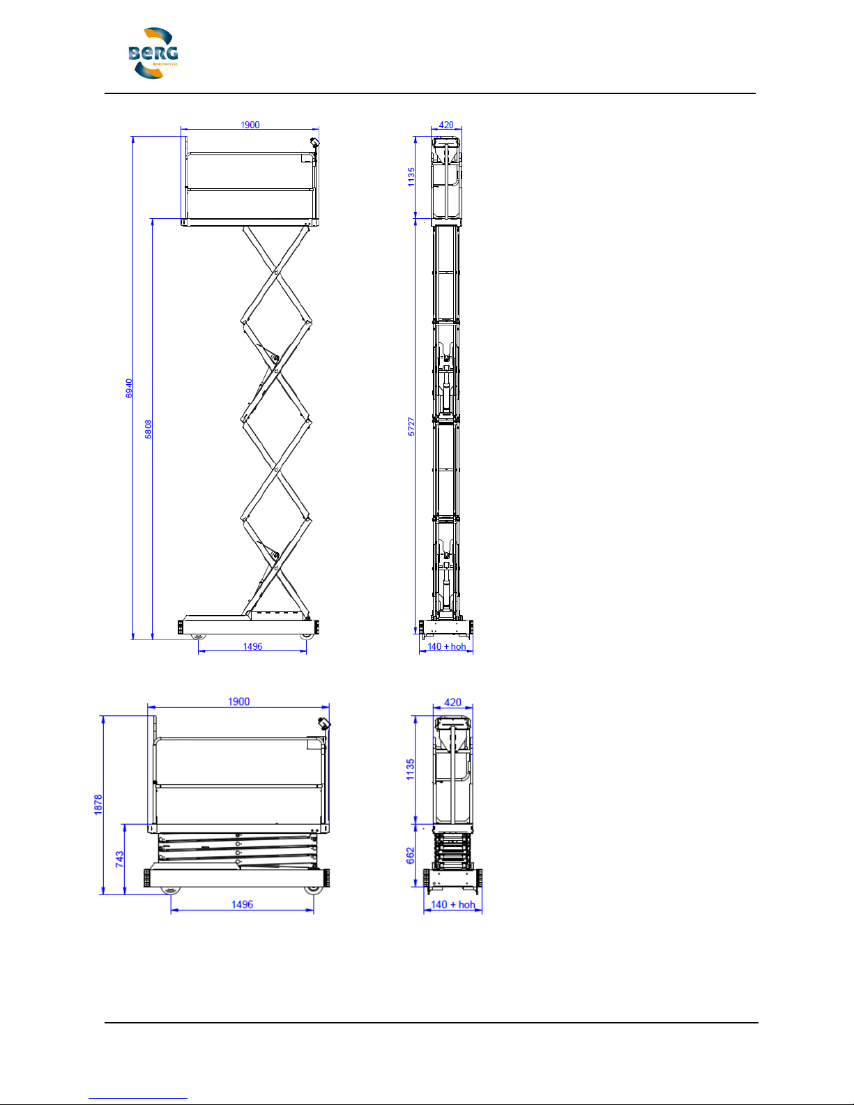
Fig. 4.0 - Maximum dimensions of the 4-scissor model up to 5.7m
Fig. 4.0 - Minimum dimensions of the 4-scissor model up to 5.7m
Page 15
Translated user manual (EN-V11) BENOMIC 15 / 43
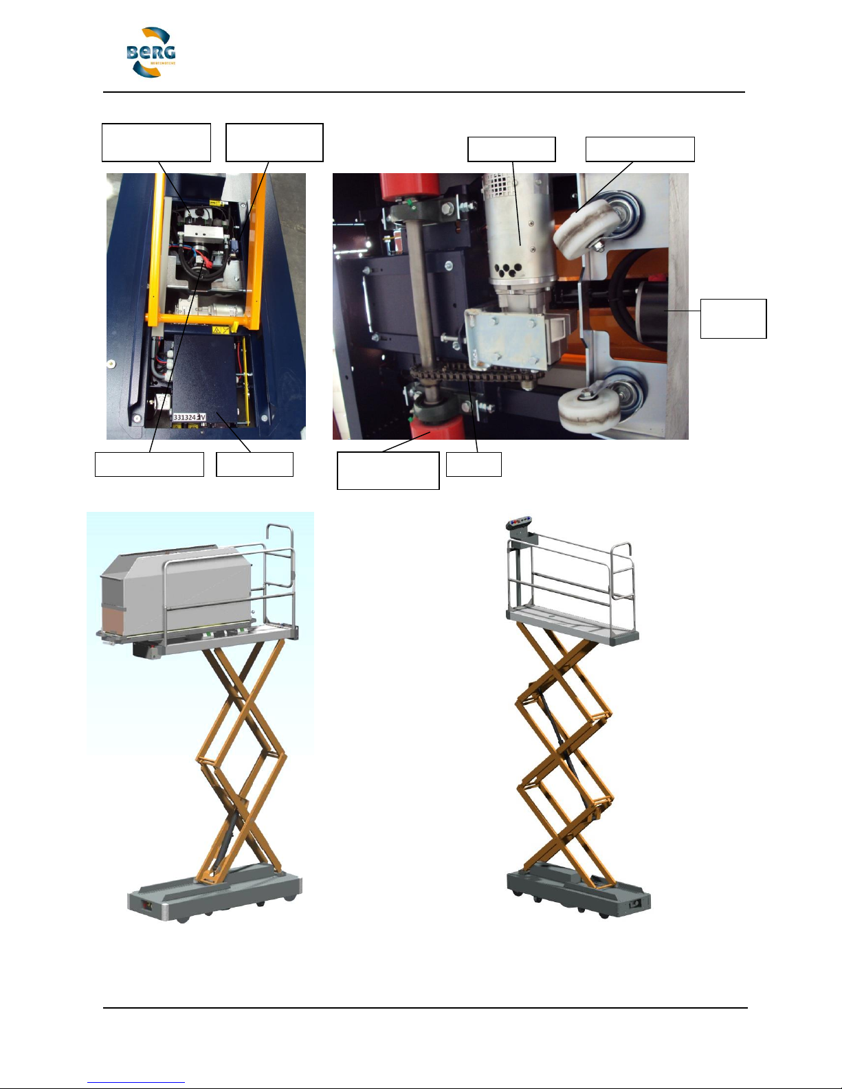
Fig. 4.3;
Left:
Benomic with heavy duty
double scissor, twin controls,
sliding rack, hopper and
rails.
Right:
Benomic 3-scissor model
without stabilizers
Hydraulic pump
Switch box
Lifting system
limit switch
Lifting swivelling
0.37kW motor
Chain
Drive wheel
flange
Hydraulic
Motor
Fig. 4.2 - Names of the parts on the lower construction of the BENOMIC
Emergency
lowering valve
Page 16

Translated user manual (EN-V11) BENOMIC 16 / 43
6. Transport
6.1 External transport
If the BENOMIC has to be moved, please carry it out as follows:
1. Collapse the scissor construction completely.
2. Pull in the lift wheels so that the trolley is only standing on the flange wheels.
3. Set the direction of travel switch to neutral (0) and the speed indicator at 0.
4. Switch off the BENOMIC at the main switch (rotate the red key at the top end
horizontally).
5. Secure the BENOMIC so that it does not slip, roll away or fall over.
6. Ensure that the BENOMIC remains dry and free of frost during transportation.
7. On arrival at the destination, the BENOMIC should be set up according to the information
given at 7.1.
6.2 Internal transport
It is also possible to transport the BENOMIC internally in the greenhouse. Preferably it should
be driven to its location on its flange wheels (see 8.3), but it can also be moved by way of forklift
truck. If moving by forklift truck, please observe the following:
1. Collapse the scissor construction completely.
2. Pull in the lift wheels so that the trolley is only standing on the flange wheels.
3. Switch off the BENOMIC at the main switch (rotate the red key at the top end
horizontally).
4. Move the forks of the forklift truck as far apart as possible and then insert them as far as
possible under the middle section of the trolley.
5. Check the opposite side to ensure that the forks have been inserted as far as possible
under the middle section of the BENOMIC machine.
6. Secure the BENOMIC to the forklift forks so that it cannot shift or tip over.
7. Carefully lift the BENOMIC off the ground until it is just sufficiently clear.
Attention!
- Never lift it higher than is necessary!
- Ensure that the forklift is capable of lifting at least 600kg!
- Remove all unattached parts and harvest containers from the platform before lifting!
- Move slowly and with great care!
Page 17

Translated user manual (EN-V11) BENOMIC 17 / 43
7. Putting into operation
The BENOMIC has been specially designed to travel on a pipe rail system. All pipe rail trolleys
are checked for functionality and safety before leaving the Berg Hortimotive factory. Before
starting up the BENOMIC, the items described at 7.1 should first be inspected.
The pipe rail system must comply with the requirements laid down by the horticulture sector
guidelines. Article 7.3 states the minimum pipe rail specifications with regard to track width, pipe
diameter and distances between supports. These minimum requirements are also shown on a
symbol (see 4.3) attached to the BENOMIC machine.
These pipe rail specifications have been taken from the horticulture sector guidelines for pipe
rail systems from the health and safety catalog in force in the Netherlands. For the complete
contents of the policy regulation please contact the Ministry of Social Affairs & Employment.
7.1 Inspection prior to putting into operation
The following items should be checked before commissioning the BENOMIC
- Loose electrical connections (proper functioning of all buttons and knobs).
- Damaged cables and/or hydraulic hoses (leaks).
- Drive, runner and lift wheels are not damaged and run freely.
- Batteries are fully charged (see battery condition indicator 8.1 no 4).
- General mechanical damage (particularly on the scissor assembly).
- Damage to and impaired visibility of the controls, symbols and warnings.
- All protective covers and caps are in place.
- The securing of the scissor assembly to the lower trolley and the rails on the scissor
(plus any sliding racks or containers).
- Proper functioning of the lifting system
- Stabilizers are properly secured (only with 3-scissor model up to 4,4m and 4-scissor
model up to 5,7m).
7.2 Horticulture sector guidelines for pipe rail systems
The BENOMIC has been specially designed to travel on a pipe rail system. This means that a
set of rails is located in every pathway between the plants which consist of two pipes of the
same diameter and having a fixed width between the pipes (centre to centre measurement).
The pipes often act as heating pipes and lie on supports having a fixed distance between each
other. The pipe rail system must satisfy the most recent requirements of the horticultural sector
guidelines for pipe rail systems. Article 7.3 also provides the minimum requirements for pipe rail
systems taken from the sector guidelines for pipe rail systems. The pipe rail system on which
the BENOMIC is intended to be used, must also comply with these requirements. All the abovementioned items should also be checked periodically according to the health and safety catalog
in force in the Netherlands. It is absolutely forbidden to use a pipe rail system that does not
comply with the sector guidelines/policy regulations. Furthermore, various tests are described in
the policy regulation for testing whether it is safe to use a pipe rail trolley on a particular pipe rail
system. These tests should be carried out prior to working with the pipe rail trolley on the
available pipe rail system.
Page 18

Translated user manual (EN-V11) BENOMIC 18 / 43
7.3 Minimum requirements for a pipe rail system
The rails (usually heating pipes) must have an external diameter of between 51mm and 45mm
and a wall thickness of at least 2mm. The minimum material specifications for the pipes is as
follows: Steel 37 (S235JR). The supports for the pipe rail system must be no greater than 1.25m
distance from each other. Where piping with a diameter of 45mm is combined with a track width
of 42cm, the distance between the supports should be no greater than one metre. Pipe rail
supports are used that correspond with, or are at least equal to the following specifications:
steel bottom plate 1.5mm thick with a stiffening profile - minimum bottom plate width of 115mm
and a length such that the bottom plate sticks out at least 70mm from the two upright supports
that carry the pipes. The centre to centre distance between the pipes should be at least 42cm.
The pipes must be stable, accurately installed and level with a maximum slope of no more than
2 either in length or in width. The pipes must also be properly attached to the supports and the
concrete track. Loose fitting pipes may not be used! A soil test bore should be carried out using
probing equipment (see policy regulation according to the health and safety catalog in force in
the Netherlands). It should have a so-called cone value on the top layer of more than 0.4 Mpa
(62 psa).
Employing a pipe rail system that is not described in the policy regulation according to the
health and safety catalog in force in the Netherlands is permitted provided that a stability test is
carried out in accordance with the pipe rail system policy regulation according to the health and
safety catalog in force in the Netherlands and where it appears that the combination of pipe rail
trolley and pipe rail system in question is in fact stable. Furthermore, the supports for this
exceptional pipe rail system must have a maximum spacing of one metre and the alignment
variation in both length and breadth must not exceed 2 degrees.
The tubes are similar or at least equal to the specifications given in the table below.
The conditions for the axle load stand in the table below.
Cat.
Track-
width
Tubediameter /
thickness
Supportdistance
Permissible axle load at
center to center size
Cat.
[mm]
[mm]
[mm]
420mm
[kg]
500mm
[kg]
550mm
[kg]
600mm
[kg]
1
420 t/m
600
51 / 2,25
max. 1000
507
548
573
593
2
420 t/m
600
51 / 2,25
max. 1250
406
438
458
475
3
420 t/m
600
45 / 2
max. 1000
345
372
372
403
4
420 t/m
600
45 / 2
max. 1250
276
298
276
323
Quality steel 37 (St37)
Wheelbase between 62.5% and 125% of the support distance.
All values for other pipe and tube rail supports should be calculated separately.
Source: The Dutch health and safety catalog in force in the Netherlands
https://agroarbo.nl/catalogus/buisrailsysteem/
Page 19

Translated user manual (EN-V11) BENOMIC 19 / 43
7.4 Alignment warnings system
The BENOMIC is fitted with an alignment indicator with an acoustic warning signal. The
alignment indicator provides an acoustic signal when the trolley is out of alignment in excess of
2. When this occurs all activities must be stopped immediately, the scissor brought down as
far as possible - exit the platform then take the BENOMIC back while walking next to the trolley.
The pipe rail system must be reset before the activities can be resumed. First of all test the
prepared section of rails with the scissor set at the lowest position and at the slowest speed. If
this does not indicate a problem, try it once again with the scissor raised but still at the slowest
speed. Resume activities if the problem no longer persists.
Try to find a good, long term solution to improve track alignment!
7.5 Stabilizers
The Benomic 3-scissors and 4-scissors must be carried out with stabilizers if the working height
is higher than 3,5 meters. It is important that the stability is ensured in order to be able to work
on height. It is not allowed to work at height if the surface is gives not sufficient bearing
capacity. For a description of the soil bearing capacity we reference to the Dutch health and
safety catalog in force in the Netherlands.
See for the operation of the stabilizers appendix 2!
Page 20

Translated user manual (EN-V11) BENOMIC 20 / 43
8. Usage
Make sure that you are familiar with the BENOMIC and its controls. Ensure that those using the
BENOMIC have received instructions and have thoroughly read and understood the safety
instructions and have also read and understood this user’s manual.
- The BENOMIC should only be put into operation when the operator is certain that there is
nobody in the immediate vicinity of the Pipe Rail Trolley.
- Always remove plant remains etc and any other obstacles from the pipe rail system.
- Keep the trolley clean and regularly remove any accumulated waste materials. Remove the
key from the main switch before carrying out cleaning activities.
- After using the BENOMIC always remove the key from the main switch.
- Service the BENOMIC regularly and store it in a dry and frost-free environment if it is out of
use over long periods.
Charge the batteries only if the battery condition indicator is in the red area. If the red
area is reached during the work process in the day you can continue working. If a
acoustic signal gives by repeat 2 signals stop immediately and charge the BENOMIC. The
charge process should by continuous until the charger shows the indication "end of
charge cycle". (after 12 hours or more!) Reed the manual of the charger. Do not charge
shortly in coffee and lunch breaks this gives serious damage to the batteries! Avoid
charging to early (battery condition indicator is in the green area) unnecessary charging
affects the capacity and life of the batteries!
ATTENTION! Injury hazard from batteries:
Avoid skin coming into contact with battery electrolyte, wear safety goggles and gloves as the
fluid is highly corrosive. Immediately rinse with soap and water after coming into contact. If the
electrolyte comes into contact with the eyes, immediately rinse in running water for at least five
minutes and call medical assistance. Always ensure sufficient supplies of soap and water at
hand and that there is assistance available within calling distance in the vicinity of the batteries.
Avoid short circuits (sparks) and ensure that it is not possible to make a connection between the
poles of the batteries. The battery cover should be undamaged. Bare patches or dents can
cause short circuits!
A highly explosive gas is released while batteries are being charged. No sparks, naked flames
or smoking nearby. Ensure good ventilation in the areas where batteries are charged and/or
stored. Ensure that metal objects cannot fall on top of the batteries as this can lead to short
circuits (sparks) and therefore explosions.
Remove any personal objects such as rings, arm bands, necklaces and wrist watches if you are
carrying out activities in the vicinity of batteries. The level of current associated with a short
circuit is enough to melt a metal finger ring for example, leading to serious burn injuries.
Page 21
Translated user manual (EN-V11) BENOMIC 21 / 43
8.1 Operation
8.1.1 Controls located on the lower trolley
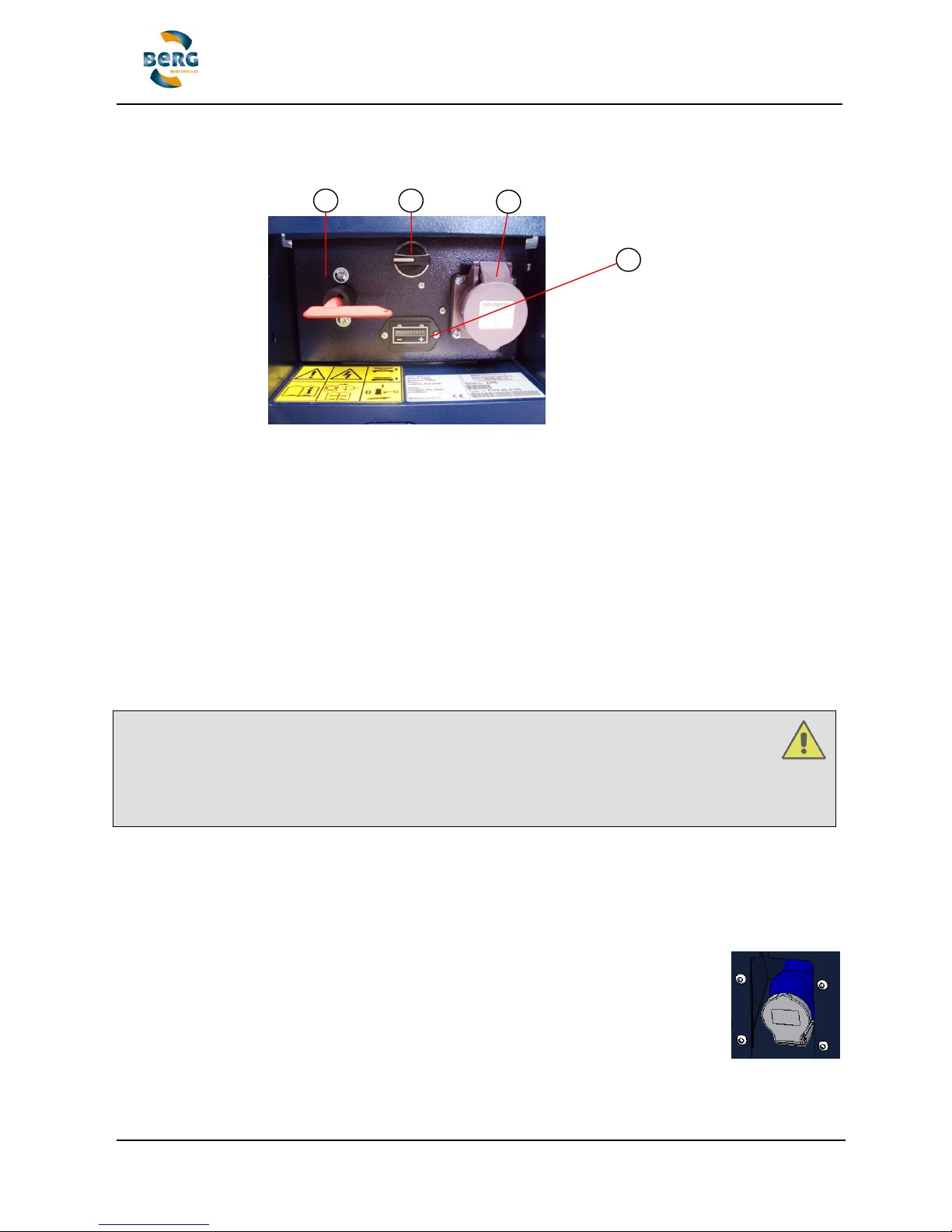
1. MAIN SWITCH/ EMERGENCY STOP
The BENOMIC can be switched on by way of the main switch. The trolley is ON if the red key is
in the direction of travel (vertical), and the trolley is OFF if the red key is at right angles to the
direction of travel. Whenever the BENOMIC is switched on the battery condition indicator lights
up (see this at no 4). Whenever the BENOMIC is not in use or being charged the red key should
be removed from the switch. The main switch also acts as an emergency stop. As soon as the
key is set to the horizontal position the trolley is completely switched off.
2. SERVICE BUTTON FOR OPERATING THE SCISSOR
By using the scissor operation selector switch it is possible to raise and lower the platform
without having to stand on it. Rotate the button clockwise (white line upwards) and the scissor
rises up for as long as the button is kept in that position. Rotate the button anticlockwise (white
line downwards) and the scissor lowers for as long as the button is kept in that position.
Attention!
- Ensure that no person or object can come either under or between the scissor
construction while it is being lowered!
- Ensure that there is sufficient space above the BENOMIC to allow the scissor to
rise up!
- Do not use this button if there is anybody on the platform!
3. SOCKET FOR THE CHARGER PLUG
The batteries are charged via this socket. With normal use, charge the batteries three times
every week - preferably Tuesday, Thursday and Friday or Saturday evenings - and at least once
every week regardless of the level of usage. Make sure that the charger plug has been
disconnected before the BENOMIC is going to be used! Always remove the charger plug when
carrying out maintenance. Only use the correct type of charger - see the charger
specifications.
If the BENOMIC is fitted with an internal battery charger (stated on the socket - see
fig. 6.2) then only an extension cable is required.
Fig. 6.1 - Controls on
the lower trolley of the
BENOMIC
Fig. 6.2 - Internal battery charger!
1 2 3
4
Page 22
Translated user manual (EN-V11) BENOMIC 22 / 43
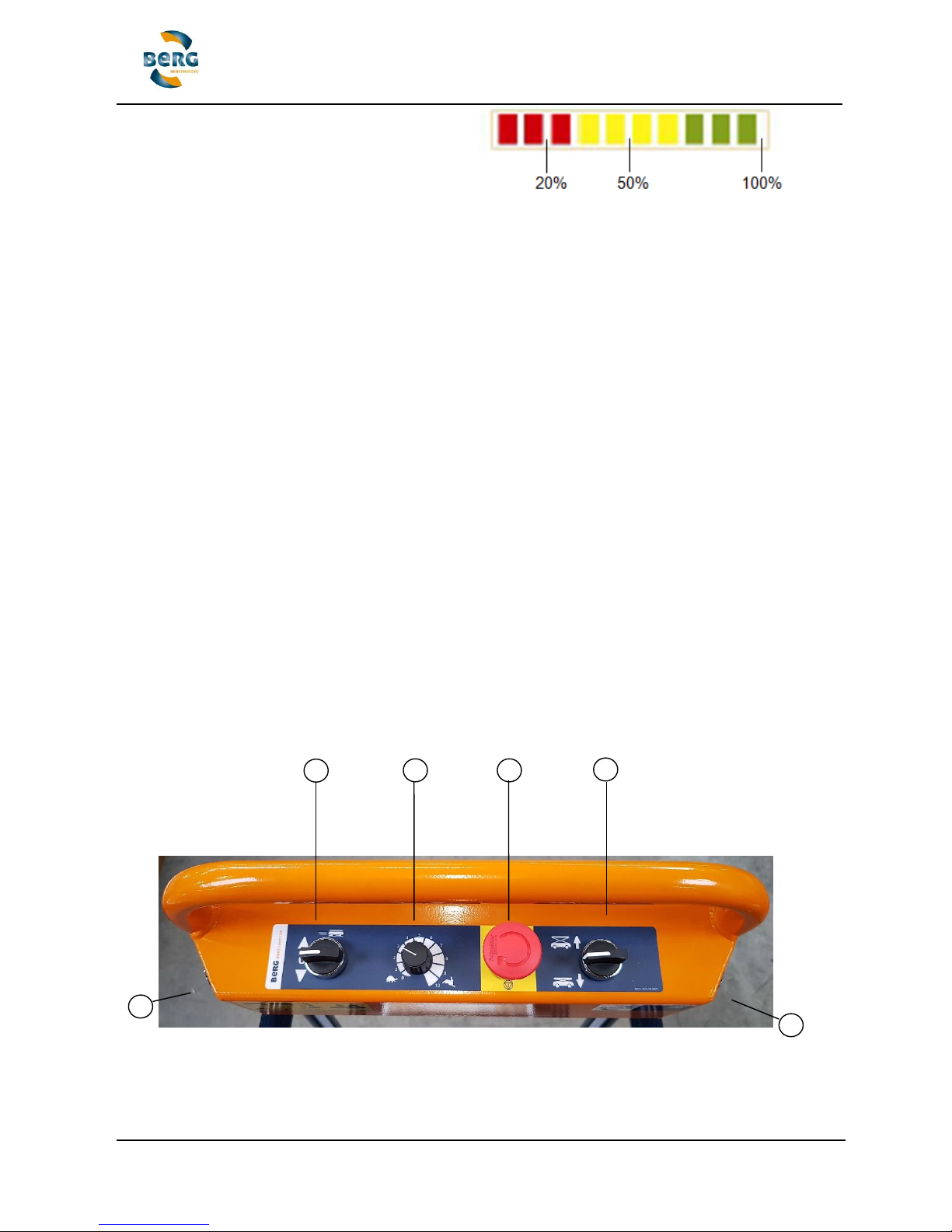
4. BATTERY CONDITION INDICATOR
The battery condition indicator provides information about the battery. The battery is full when
all the leds are lit - the fewer leds lit up, the lower the state of charge. The leds are coloured
green, orange and red. The battery is full (80 - 100%) when the red, orange and green leds are
lit - it is half full (40 - 70%) when the orange and red leds are lit - the battery is completely
discharged (20 - 30%) when only the red leds are lit. Charge the batteries when the battery
indicator is in the red zone. If this occurs while working, there is normally enough power to last
until the end of the day. If a acoustic signal gives by repeat 2 signals stop immediately and
charge the BENOMIC. Switch OFF the BENOMIC with the key switch before connection the
charger. The charge process should by continuous until the charger shows the indication "end
of charge cycle". (after 12 hours or more!) Reed the manual of the charger.
Avoid charging to early (battery condition indicator is in the 50 - 100% area) unnecessary
charging affects the capacity and life of the batteries!
Try to charge always when the battery condition indicator is in the 20% area this has the
following benefits:
Less charge cycles is beneficial for the battery life time
Less battery water consumption
Less energy consumption
A fault has been detected on the BENOMIC if all the battery condition indicator leds flash
intermittently. In such cases unlock (pull out) the emergency stop button (8) and switch the
direction switch (6) to neutral, switch OFF and then ON again with the main switch (1).
5. FOOT PEDAL
The foot pedal (5) is mounted in the platform (page 11), the BENOMIC STAR will drive in the
desired direction as long as the foot pedal is actuated.
8.1.2 Controls located on the platform
Fig. 6.3 - Control panel
6 7 8
9
10
10
Page 23

Translated user manual (EN-V11) BENOMIC 23 / 43
6. DIRECTION OF TRAVEL / REVERSE DIRECTION SWITCH
The direction of travel can be chosen by setting the selector switch in the desired position. The
neutral position on the switch is at the centre (0). When leaving the BENOMIC always put the
switch in neutral!
7. SPEED REGULATING SWITCH
0 = stop 10= maximum speed
8. EMERGENCY STOP BUTTON
Only to be used in the case of emergency! Disconnect normally using the main switch (1).
- Press = stop and switch off
- Turn-pull out = release
When automatic travel is stopped via the EMERGENCY STOP BUTTON, the BENOMIC will
indicate error status (the battery condition LEDs will flash intermittently). The error status can be
reset by putting the main switch to OFF, the direction of travel switch to 0, and then followed by
putting the main switch back to ON again. If this does not reset, rotate the speed regulating
switch to 0 and then reset to the desired speed.
9. LOWERING RAISING THE WORK PLATFORM SWITCH
The work platform can be lowered by turning the switch to the down position. The platform
descends for as long as the switch is held in. Once the scissor has almost fully collapsed, the
lowering process slows down in the interests of comfort and also to safeguard the equipment.
Watch out for persons or objects in the vicinity of the scissor assembly while lowering!
The work platform can be raised by turning the switch to the up position. With the double scissor
model, the scissor rises up to the maximum height of 3 or 3.5 metres for as long as the switch is
held in - this is 3.5 metres for the triple scissor model without using the stabilizers, and 4.4
metres for the triple scissor model with the stabilizers in place, and 5.7 metres for the quad
scissor model with the stabilizers in place.
FOR THE OPERATION OF THE STABILIZERS APPENDIX 2!
10 RAISING THE TROLLEY HYDRAULICALLY
By pressing (1x) this button the BENOMIC rises to the fully extended position, thereafter it can
be manually rotated and put into position.
The button on the right side is for activating the lifting wheels system.
The button at the left side for deactivating.
Attention!
- Only raise the equipment when it is on a flat surface (concrete path or main pathway)
- Never raise it while on the pipes or on a sloping path!
- Lower the platform completely before raising the BENOMIC!
- Think about toes and feet when lowering the BENOMIC!
Page 24
Translated user manual (EN-V11) BENOMIC 24 / 43
8.2 Emergency lowering valve
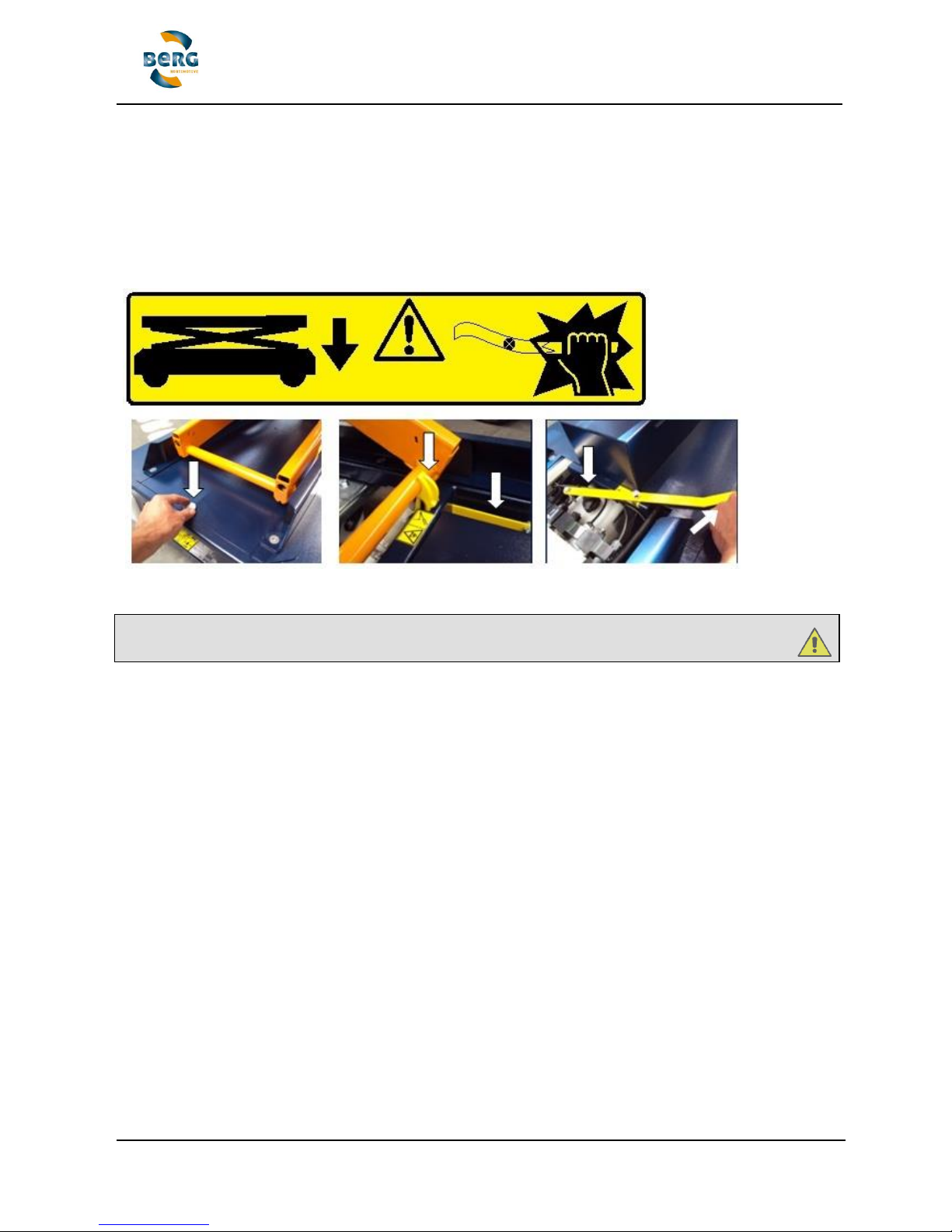
The emergency lowering valve is located below the scissor and under a cover plate. If the
scissor refuses to lower via the controls on the platform (9) as well as those at top end on the
BENOMIC (2), remove the cover by unscrewing the bolt and putting the plate to one side
through the scissor legs. The emergency lowering valve can now be pressed used the handle
supplied. Beware of hands, arms or head becoming wedged between the scissor legs or
under the platform!
Attention! Remove your hands before they become wedged! Only use this function in
real emergencies!
8.3 Moving the BENOMIC on the main pathway
There are two methods for moving the BENOMIC on the main pathway. Always walk beside the
trolley - never in front! The first method is to move it on the flanged wheels. Set the direction of
travel and the speed (maximum position 4) and put the pedal function to pedal=accelerator.
Press the foot switch and the BENOMIC will travel in the desired direction.
The second method is to put the trolley onto its lift wheels. Press button 10 on the right hand
side and the BENOMIC is raised on its lift wheels. The BENOMIC can now be easily rotated and
travel along sideways. Never leave the BENOMIC on the lift unattended and always walk at
its side!
8.4 Out of use
When the BENOMIC is not being used please ensure that the scissor is in the lowest position
and the lift wheels are fully retracted so that the trolley is standing on its flanged wheels.
Disconnect via the main switch and store it with fully charged batteries in a dry and frost-free
environment. The BENOMIC should preferably be connected to a trickle charger. If not, the
batteries should be charged at least once a month (even when the BENOMIC is out of use over
long periods). Ensure that the ground underneath is level. When the BENOMIC is being put
back into use after a long period in storage, it should be inspected as described in article 7.1
(Inspection prior to putting into operation).
Fig. 6.5 - Left: unscrew bolt and remove cover. Centre - take out the handle. Right - press the
bolt in the gap against the pin on the emergency lowering valve!
Page 25

Translated user manual (EN-V11) BENOMIC 25 / 43
8.5 Cleaning
Remove any plant remains, leaves etc and brush off any sand and dust, on a regular basis.
Clean the Pipe Rail Trolley with a dry/damp cloth or soft brush. Provided it is completely dry, the
BENOMIC can be cleaned using compressed air. Never pour water over the BENOMIC or clean
it using a steam or high-pressure water cleaner which can lead to serious damage to the
electrical circuits!
Every week sand and dirt should be removed from the chassis for the scissor sliding block.
See also Appendix 4: Cleaning the powder coating
8.6 Harvest container
As an optional extra for the BENOMIC model with the heavy duty double scissor, a harvest
container is available that can be put onto the platform in combination with top end controls and
a sliding rack. The harvest container along with its accessories (rails/sliding rack, etc) must only
be supplied by Berg Hortimotive The harvest container serves as a buffer for harvesting
peppers. The maximum load capacity of the platform should be reduced by the weight of the
container and the sliding rack. The maximum loading capacity of 450/550kg must never be
exceeded!
8.7 Problems, causes and solutions
Problem A : The BENOMIC does not move
Cause : Key switch is OFF
Solution : Turn on the key switch (vertical position)
Emergency stop locked on
Unlock the emergency stop button (pull out)
Batteries flat (red leds 2x flashing on battery condition indicator)
Charge up the batteries with the charger
Speed indicator at 0
Set a speed
Direction of travel at 0 or inconsistent
Set direction of travel (or equivalent)
Error status (leds flashing intermittently)
See no 4 on page 21
Battery terminals making poor contact
Clean and re-tighten battery terminals
Faulty foot switch
Replace foot switch - consult your dealer
Broken cable at foot switch
Repair cable break or replace switch
Lift does not fully collapse or limit switch is defective
Collapse lift system completely (10) or check switch
25 amp safety fuse in 0 position.
Consult your dealer
Other causes.
Consult your dealer
Page 26

Translated user manual (EN-V11) BENOMIC 26 / 43
Problem B : The platform will not go up or down
Cause : Lifting system limit switches not connected or defective.
Solution : Completely collapse lift system and check switch
Batteries flat. (red leds 2x flashing on battery condition indicator)
Charge up the batteries with the charger
Battery terminals make bad contact
Clean and re-tighten battery terminals
Key switch is OFF
Turn on the key switch to vertical position
Emergency stop button pressed in
Unlock emergency stop button (pull out)
Overload
Reduce load - maximum 120/250/450/550kg
Hydraulic fluid level too low
Top up hydraulic fluid (scissor raised - information from supplier)
Switch/push-button defective
Try using the scissor control service button (2) next to the main switch
80 amp fuse blown
Consult your dealer
Control current 10A fuse is blown
Consult your dealer
Stabilizers not extended (only with 3-scissor and 4-scissor model)
Turn the stabilizers out enough for extra support
Problem C : Speed difficult to regulate
Cause C : Speed regulator switch is faulty
Solution : Consult your dealer
Drive motor regulator is faulty
Consult your dealer
Problem D : BENOMIC has fallen over
Cause D : - Wrongly lifted with forklift truck
- Unstable pipe rail system
- Too much manual pressure
- Overloaded
- Alignment indicator ignored
- Run into the path next to the pipes
- Lifting on the pipes or ground surface not level
Solution : 1. Switch off the trolley
2. Lift the trolley back into position
3. Remove caps and covers
4. Disconnect batteries
5. Clean the trolley
6. Assess the damage
7. Identify cause and find solution (remove)
8. Carry out checks according to table in chapter 7
9. Carry out checks according to 7.1
!!!Beware of fluids - battery acid is extremely corrosive!!!
Page 27

Translated user manual (EN-V11) BENOMIC 27 / 43
8.8 Disposal
If your BENOMIC has to be disposed of, for whatever reason, this must be carried out by
your supplier or by another company that specialises in dismantling vehicles. On no account
should you take your BENOMIC to a scrap dealer or to the rubbish tip. The BENOMIC
should be dismantled and the chemical parts including hydraulic fluids and battery acid
removed separately.
Return faulty batteries to your local authority cleansing department or your supplier.
Treat oil as a chemical waste.
9. Repairs & maintenance
The BENOMIC is a very high quality product. In order to guarantee that the high level of quality
remains, it is vital that the maintenance scheme given below is strictly adhered to. Repairs and
maintenance activities should be recorded in the maintenance log book (see appendix 1). The
employer is also responsible for periodically checking tools and equipment according to the
current national regulations covering this subject.
Disconnect the BENOMIC by the main switch before starting maintenance:
Maintenance - Check
Tools
Day
Week
Month
Year
Battery sufficiently charged
Battery condition indicator
X Damage to the control equipment
Visual X
Damage to and visibility of the symbols and
stickers
Visual X
Foot pedal + platform cleaning
Brush / Damp cloth
X
Clean control panel
Brush / Damp cloth
X
Clean chassis sliding blocks for scissor
Brush / Damp cloth
X
Check for leaks and damage to cables and
hoses
Visual X
Check for waste material or string etc twisted
around wheels and chains
Visual X
General mechanical damage
Visual X
Check raising and lowering movements for
jamming (low hydraulic fluid levels)
Hydraulic fluid
ISO Viscosity Grade 46
X
Check for height safety without stabilizers
Visual - only the 3-4 scissor model
X
Charge batteries when needed or at least once
a month
Battery charger
X Check battery electrolyte levels (plates covered
1cm depth electrolyte - see Appendix 3)
Distilled water, protective gloves
and safety goggles
X
Check the operation of the alignment warning
Test > 2 degrees
X
Check hydraulic components under the cover
plate for leakage (pump and valves)
Tools for removing cover plate bolt
X
Grease lift wheels, drive chain and ball
bearings
Grease for ball bearings and
chains or a universal lubricating
grease
X
Check chain tension (see 9.5)
Open-ended spanner
X
Fixing caps on the scissor shafts
Visual X
Have the motor's carbon brushes cleaned
and those smaller than 1 cm replaced (see
9.4)
Compressed air / Visually
X
Grease all hinged parts of the scissor assembly
(see 9.2)
Grease gun and grease
X
Grease all hinged parts in the lift system
Grease gun / WD40 / lubricating
grease
X
Check the welds on the scissor construction for
cracks (hair cracks) and rust.
Visual X
If it appears from the above checks that there is a fault with the BENOMIC, please contact your
BENOMIC dealer immediately. Continuing to use the trolley with the identified defects can be
very dangerous and is therefore forbidden!
Page 28
Translated user manual (EN-V11) BENOMIC 28 / 43
9.1 Specialist maintenance
Maintenance and repairs to the items listed below may only be carried out by qualified
specialists recognised by Berg Hortimotive:
- Activities connected with the electrical system (excluding the exchange of the foot pedals
and batteries)
- All work concerning the hydraulic system.
- All work concerning the drive motor with reduction box with the exception of the following:
cleaning, resetting or replacing the chain or sprocket wheels.
9.2 Maintenance in and around the scissor assembly
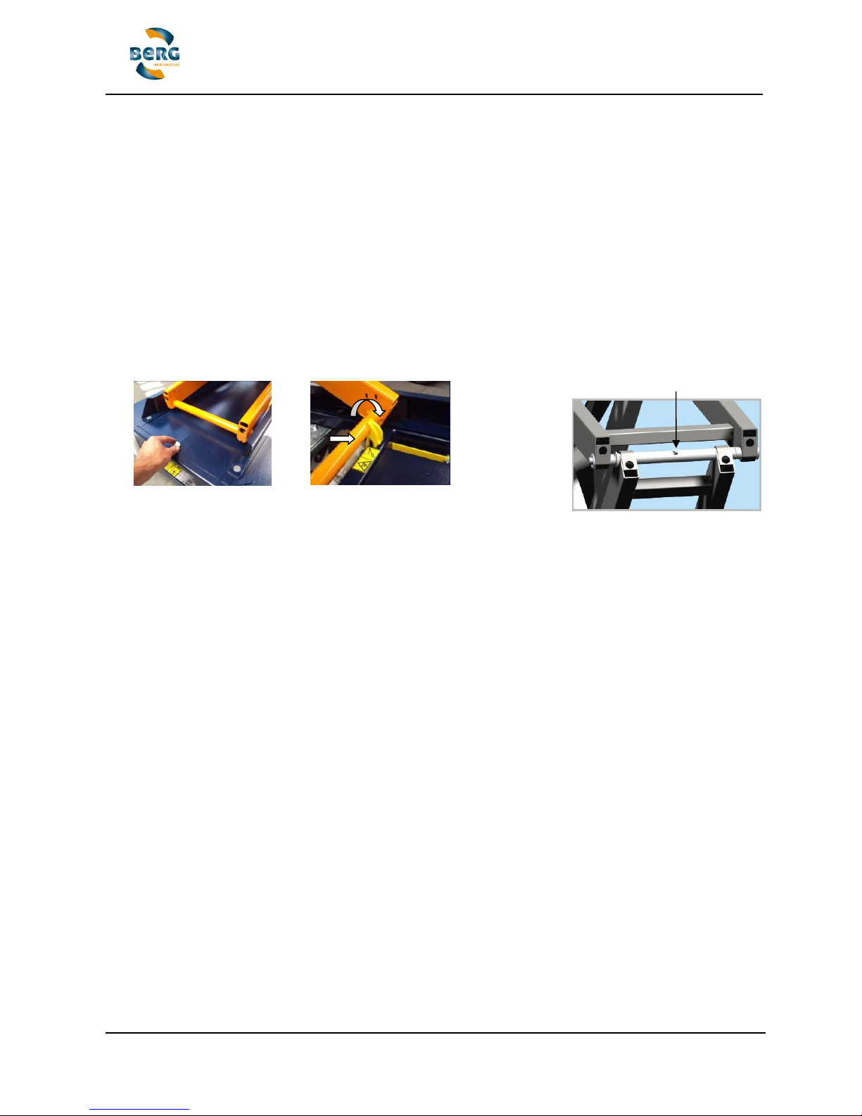
The scissor wedges should be used when working or carrying out maintenance in or around the
scissor assembly. Remove the cover plate (picture A). Extend the catch while the scissor is
raised allow the scissor to lower (B) until it touches the safety catch. Disconnect the BENOMIC
by the main switch.
The scissor shafts are mounted on bearings by way of bushes. The
inner scissor parts are connected to the outside parts by way of a
continuous shaft. In order to avoid rust forming on the shafts they
should be greased at least once annually using a universal lubricating grease applied with a
grease gun. Raise the scissor and put the wedges into place to block them as described (see
picture 7.1). Put the grease gun over the grease nipples and pump in the lubricant until it flows
out of the outer edges of the bearing bushes.
9.3 Pipe rail system maintenance
The pipe rail system over which the BENOMIC travels requires to be checked periodically. The
system should always satisfy the horticulture sector guidelines for pipe rail systems in
greenhouses (see 7.2). It is prohibited to use the Pipe Rail Trolley on a pipe rail system that
does not satisfy these guidelines. The employer is also responsible for periodically checking
tools and equipment according to the current national regulations covering this subject.
Always ensure that the pipes have sufficient support and are spaced at no more than 1.25m
apart and that the supports are not at an angle and the pipes are firmly in place. Furthermore,
the pipes must be attached to a concrete pathway and should not be loose. The welded endstop on the pipes (building wall) should be at least 5cm high - check at each change of season
whether the end-stop is still upright and not bent over or split or cracked. The ground under the
pipe rail system should be dry, flat and hard. Soft or wet patches should be treated accordingly
and any subsidence dealt with permanently.
Grease nipple 6x1 H2-M 45gr
A
B
Fig. 7.2 - Location of the scissor
shaft grease nipples
Fig. 7.1 A-B Extending the scissor wedge
Page 29
Translated user manual (EN-V11) BENOMIC 29 / 43
Fig. 7.3 - Inspection motor carbon brushes
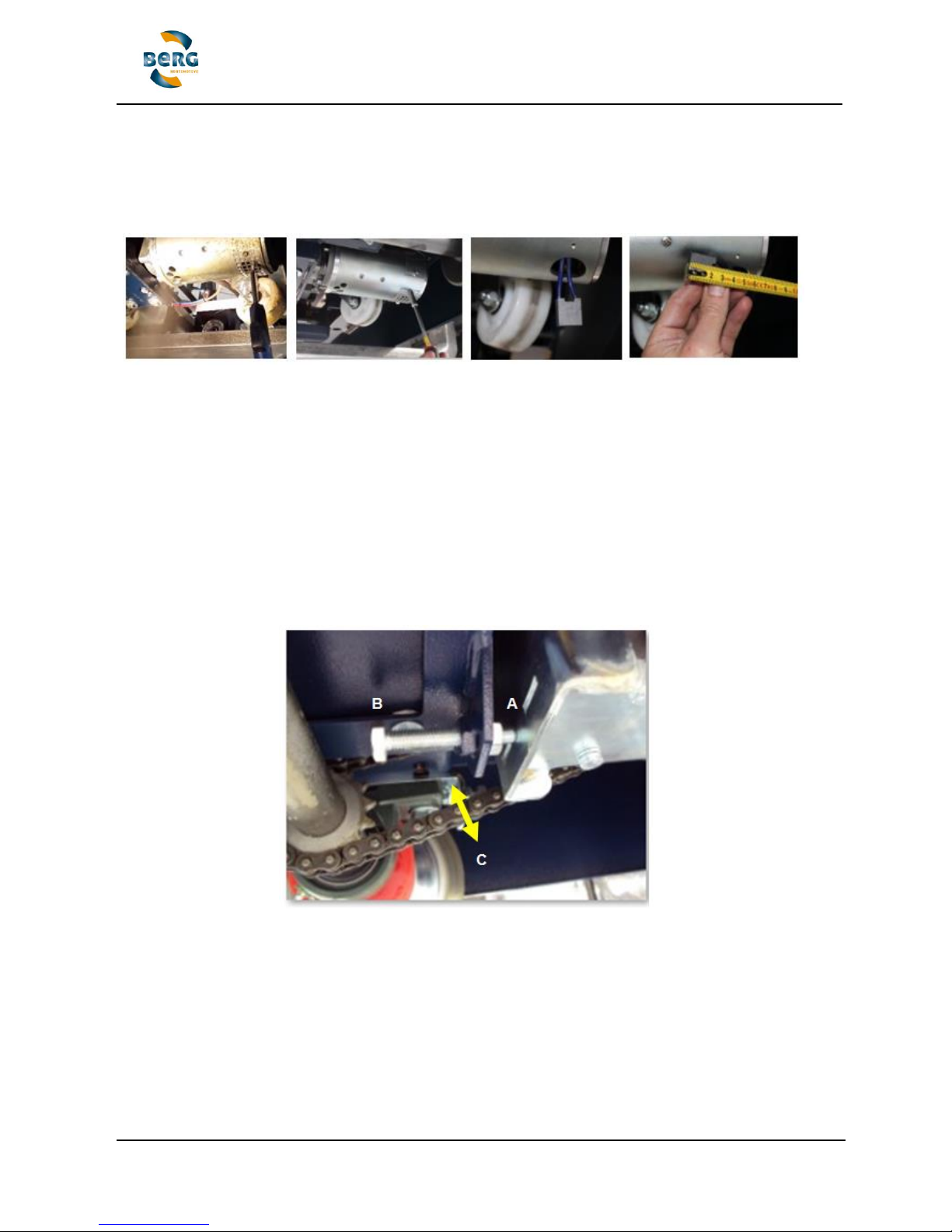
9.4 Inspection carbon brushes
1. Raise the BENOMIC STAR thereby making the motor accessible. 2. Blow the carbon brushes
clean with compressed air 3. Unscrew the grill, 4. Pull up the carbon brush, 5. Carbon brushes
less than 1 cm long should be replaced - consult your dealer.
9.5 Tensioning the chain
The chain tension should be approximately 1cm - if not, carry out the following:
1. Switch off the BENOMIC at the main switch and remove the key from the slot to avoid the
BENOMIC being switched on again.
2. Lift up the trolley using a forklift truck, for example (see 6.2 Internal transport)
3. Unscrew the blocking nut (picture A)
4. Tighten the chain by rotating the adjusting bolt (picture B)
5. Fix the adjusting bolt in place by fully tightening the blocking nut again (picture A)
* ensure that the chain play is approximately 1cm (picture C)
C
Fig. 7.3 A-B-C - Tensioning the chain
Page 30

Translated user manual (EN-V11) BENOMIC 30 / 43
9.6 Charging the Batteries
Charge the batteries according to the status indication of the battery condition indicator
between 50 and 20% residual capacity and try to approach this advice as closely as
possible to the 20% residual capacity.
BATTERY CONDITION INDICATOR
The battery condition indicator provides information about the battery. The battery is full when
all the leds are lit - the fewer leds lit up, the lower the state of charge. The leds are coloured
green, orange and red. The battery is full (80 - 100%) when the red, orange and green leds are
lit - it is half full (40 - 70%) when the orange and red leds are lit - the battery is completely
discharged (20 - 30%) when only the red leds are lit. When the red leds is indicate work the
whole day true and recharged at the end of the day! If a acoustic signal gives by repeat 2
signals stop immediately and charge the BENOMIC. Switch OFF the BENOMIC with the key
switch before connection the charger. The charge process should by continuous until the
charger shows the indication "end of charge cycle". (after 12 hours or more!) Reed the manual
of the charger.
Avoid charging to early (battery condition indicator is in the 50 - 100% area) unnecessary
charging affects the capacity and life of the batteries!
Try to charge always when the battery condition indicator is in the 20% area this has the
following benefits:
Less charge cycles is beneficial for the battery life time
Less battery water consumption
Less energy consumption
Charge the batteries at least once every month using a suitable charger, regardless the
level of usage! Ensure that the batteries are not completely flat before recharging!
See also the instructions of Appendix 3 safety data sheet battery!
Page 31

Translated user manual (EN-V11) BENOMIC 31 / 43
10. Technical specifications
BENOMIC pipe rail trolley with hydraulic scissor and lift system type number 51xx.xx.xxxx
Type:
Dimensions[mm]:
2-scissor
3m model
standard
2-scissor
heavy duty
3m model
2-scissor
3.5m model
standard
2-scissor
heavy duty
3.5m model
centre to centre
dimension
420-800
420-800
420-800
420-800
Length
1940
1940
2253
2253
Width
c to c + 180
c to c + 180
c to c + 180
c to c + 180
Lower trolley step height
from concrete
255
255
255
255
Step height to platform at
lowest position
537
537
554
554
Height of the control
column on platform
1100
1100
1100
1100
Work platform length
1900
1900
2151
2151
Work platform width
420
420
420
420
Maximum work platform
height
2990
2990
3524
3524
Maximum Load capacity
[kg]
250
450/550
250
450/550
Maximum lateral force [N]
110
110
110
110
Weight [kg] (c. to c. 550)
410
410
480
480
Motor capacity Moving
[kW]
0.37
0.37
0.37
0.37
Motor capacity Hydr. [kW]
1.2
1.2
1.2
1.2
Hydr.fluid Visc. 46 [L]
1.5
2.4
1.7
2.4
Max travel speed on pipes
[m/min]
57
57
57
57
Max travel speed on
concrete [m/min]
112
112
112
112
Lift speed [sec] *
0.13
0.13
0.13
0.13
Lowering speed [sec] *
* with load of 80 kg
0.14
0.14
0.14
0.14
Voltage [Volt DC]
24
24
24
24
Battery capacity [Ah]
2x130
2x130
2x130
2x130
Noise level [dB]
<70
<70
<70
<70
Hopper weight [kg]
-
± 90
-
± 90
Sliding rack weight [kg]
-
± 20
-
± 20
Wheelbase [mm]
1496
1496
1817
1817
Page 32

Translated user manual (EN-V11) BENOMIC 32 / 43
Type:
Dimensions[mm]:
3-scissor model
excl. stabilizers
3-scissor model
incl. stabilizers
4-scissor model
incl. stabilizers
centre to centre
dimension
420-800
420-800
420-800
Length
1940
1940
1940
Width
c to c+180
c to c + 180
c to c + 180
Lower trolley step height
from concrete
255
255
255
Step height to platform at
lowest position
628
628
755
Height of the control
column on platform
1100
1100
1100
Work platform length
1900
1900
1900
Work platform width
420
420
420
Maximum work platform
height
3500
4400
5700
Maximum Load capacity
[kg]
120
120
120
Maximum lateral force [N]
110
110
110
Weight [kg] (c. to c. 550)
450
470
535
Motor capacity Moving
[kW]
0.37
0.37
0.37
Motor capacity Hydr. [kW]
1.2
1.2
1.2
Hydr.fluid Visc. 46 [L]
2.4
2.4
2.4
Max travel speed on pipes
[m/min]
57
57
57
Max travel speed on
concrete [m/min]
112
112
112
Lift speed [sec] *
0.13
0.13
0.13
Lowering speed [sec] *
* with load of 80 kg
0.14
0.14
0.14
Voltage [Volt DC]
24
24
24
Battery capacity [Ah]
2x130
2x130
2x130
Noise level [dB]
<70
<70
<70
Hopper weight [kg]
- - -
Sliding rack weight [kg]
- - -
Wheelbase [mm]
1496
1496
1496
Physical operating conditions
Ambient temperature,
Transport & Storage : 5 to +40 degrees Celsius
Working : 5 to +40 degrees Celsius
Rel. Humidity (RH) : 0% to 90%, not condensing
Lighting : Normal ambient lighting.
The machine is not designed to be used outdoors.
The machine is not suitable for operating in explosive atmospheres.
Page 33

Translated user manual (EN-V11) BENOMIC 33 / 43
11. EC Declaration of Conformity
(according to Appendix IIA of the Machine Guidelines)
Berg Hortimotive
Burg. Crezeelaan 42a
2678 KZ De Lier – the Netherlands
T: +31 (0)174 – 517700
www.berghortimotive.nl
Hereby declare under their own responsibility that:
- Pipe rail trolley type BENOMIC with double hydraulic scissor and hydraulic lift
wheels up to 3 or 3.5 metres in height
- Pipe rail trolley type BENOMIC with double hydraulic scissor for the harvest
container (heavy duty finish) up to 3 metres in height
- Pipe rail trolley type BENOMIC with triple scissor and hydraulic lift without
stabilizers up to 3.5 metres in height
- Pipe rail trolley type BENOMIC with triple scissor and hydraulic lift with stabilizers
up to 4.4 metres in height
- Pipe rail trolley type BENOMIC with fourfold scissor and hydraulic lift with
stabilizers up to 5.7 metres in height
Part number: ..........
Serial number: ........
- Meets the requirements of the new Machine Guidelines 2006/42/EG
Is in accordance with the following EG directives:
- Electromagnetic Compatibility Directive (EMC), 2004/180/EG (according to the latest
edition)
- Low Voltage Directive 2006/95/EG (according to the latest edition)
Is in accordance with the following harmonisation standards:
[1] NEN-EN 953:1998+A1Ontw. Draft Machine Safety. General requirements for the design
and construction of safety equipment (fixed, moveable), CEN
[2] NEN-EN 60204-1:2006, Safety of machines – Electrical equipment on machines – Part 1 :
General requirements
Conforms to the Dutch health and safety catalog in force in the Netherlands.
The Netherlands, De Lier, dated ..........
Authorised signatory .....................
Page 34

Translated user manual (EN-V11) BENOMIC 34 / 43
Appendix 1: Maintenance log book
Repairs and/or maintenance activities described on the form below.
Date
Description of repair/maintenance
Type no:……………… Serial no:…………………………
Name of
company/engineer
Page 35
Translated user manual (EN-V11) BENOMIC 35 / 43
Appendix 2: Operation of the stabilizers
The Benomic 3-scissors and 4-scissors must be carried out with stabilizers if the working height
is higher than 3,5 meters. It is important that the stability is ensured in order to be able to. It is
not allowed to work at height if the surface is gives not sufficient bearing capacity. For a
description of the soil bearing capacity we reference to the policy regulation according to the
health and safety catalog in force in the Netherlands.
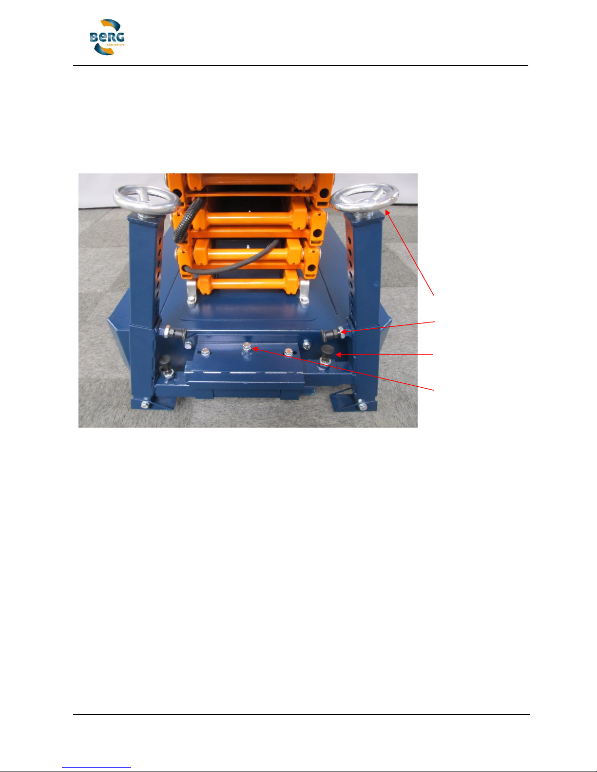
Fig. 1. Summary stabilizers
Drive to the place where you want to work at height and put the direction switch (6) to the
neutral position and put also the speed regulator button (7) to zero. Leaf the platform at the
lowest position to activate the stabilizers.
Hand wheel
Locking pin vertical
Locking pin horizontal
Limit switch adjust bolt
Page 36
Translated user manual (EN-V11) BENOMIC 36 / 43
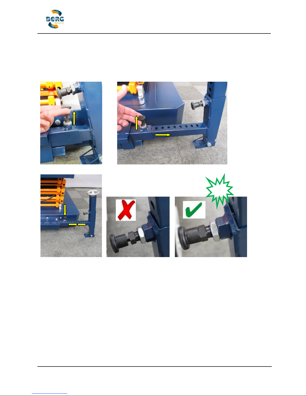
Locking horizontal
Release the locking pin by pulling up the knob (Fig. 2). Hold the knob and pull out the stabilizer
arm to the maximum position (Fig. 3) Let loose the locking pin knob and be sure that the locking
pin is fixed in a locking hole (Fig. 4) If not so move the stabilizer arm until the pin is locked in a
locking hole near to the maximum position. Repeat this operation also for the other side.
Fig. 2. Release locking pin Fig. 3. Pull out the stabilizer arm
CLIK
Fig. 4. Locked stabilizer arm WRONG locked GOOD locked
Page 37
Translated user manual (EN-V11) BENOMIC 37 / 43
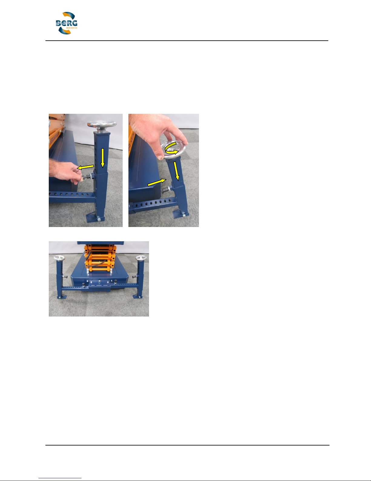
Locking vertical
Release the locking pin by puling up the knob (Fig. 5). Move the vertical post downwards until it
reach the ground. Let loose the locking pin knob and be sure that the locking pin is fixed in a
locking hole. Repeat this operation also for the other side!
Turn both hand wheels so that the post is going downwards to the ground (Fig. 6), there should
be no movement in the middle of the stabilizer construction after the described action. The limit
switch should be switched now and working safely at height is now possible (Fig. 7).
Fig. 5. Locking pin vertical Fig. 6. Hand wheel
Fig. 7. Ready to use
The Benomic is unable to drive when the stabilizer is forced to the ground!
Make ready for driving
Make all the above steps the opposite way to make the Benomic ready to drive. Be sure that the
stabilizer post and arms are maximum inside and locked to provide unintended sliding out of the
stabilizer parts.
Page 38

Translated user manual (EN-V11) BENOMIC 38 / 43
Appendix 3: Safety data sheet battery
Battery advice
The next chapter provides advice for efficient use, safety and maintenance.
Efficient use of the pipe rail trolley and battery
The following instructions are intended to promote. Efficient use of the pipe rail trolley and the
useful life of the batteries.
Basic principles:
• At high speeds, the battery are faster empty.
• A lot of starts and stops giving higher consumption.
• By using the pipe rail trolley the residual capacity and battery voltage drops slowly, the power
consumption increases. As a result, there is more heat in engine, speed control when the
batteries become more empty.
• Worn rollers or screwed rope and rusty chain (bad maintenance) results in a higher
consumption. (See instructions for servicing our site:
http://www.berghortimotive.com/service/bsa-film)
• The (too) deep discharge batteries shortens the lifespan.
• Timely loading and proper maintenance will prolong the life of the batteries.
• Timely loading reduces heat generation in motor and speed controller and battery charger.
Efficient use:
• Limit travel speed as well as possible at the pace of work (potentiometer).
• By following the above recommendations will also increase employee productivity.
Safe use of batteries
Below you can find recommendation for the use and maintenance of batteries.
WARNING!
- An explosive gas is given off the batteries while being charged - no sparks, and naked
flames and smoking are strictly forbidden
- Charging should be carried out in a well ventilated space and only using a suitable
battery charger!
- The battery electrolyte levels should be checked every month! The battery electrolyte
level should be 1cm above the plates
- Top up only with distilled (demineralised) water - wear protective gloves!
- Always fill the batteries after charging and never fill above the marker in the hole of the
battery cell. (See also the instruction sheet traction batteries)
Page 39
Translated user manual (EN-V11) BENOMIC 39 / 43
Discharge levels of less than 20% capacity can affect the life of the batteries and the charger
negatively. Charge the batteries when the battery discharge indicator is in the red area - this will
benefit the life of the batteries, the motor and the electrical equipment! Always recharge a flat
battery immediately - this increases its lifespan markedly. In connection with this, it is advisable
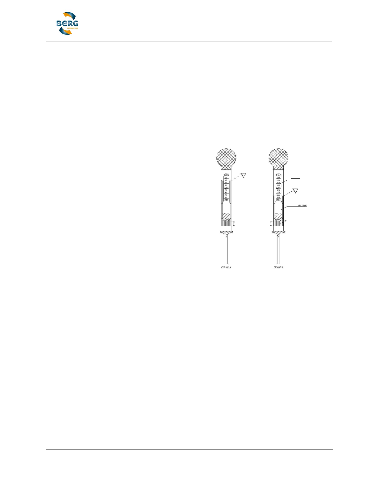
to check the specific gravity of the battery electrolyte every week, minimum every month, using
a hydrometer (fig. A+B and table below).
The specific gravity (sg) of the electrolyte of a fully charged battery should be 1280 g/l:
Disconnect the BENOMIC by the main switch before
starting to charge the batteries. When charging
batteries always connect up the batteries before
switching on the charger. When the batteries are fully
charged, first switch off the charger, then disconnect the
batteries.
Overcharging batteries can also result in damage to the
battery owing to the electrolyte 'boiling off'.
It is advised to use a modern charger equipped with an
automatic 'fully charged' cut-out - these are available
from Berg Hortimotive Use only chargers suitable for
24V-110Ah - Lead/acid batteries! (see charger
instructions)
Do not interrupt the charging process - allow the batteries to become fully charged - check the
charger indicator.
During battery charging the BENOMIC should not be repaired, cleaned or have any other
activities performed on it.
Turn off everything that consumes electricity on the equipment before removing the batteries to
avoid sparking.
Disconnect the earth cable (-) first before removing the batteries. When reinstalling the
batteries, connect the earth cable (black) last.
WARNING!
Always plus (+ = red) to the positive pole, and minus (- = black) to the negative pole.
Battery electrolyte is highly corrosive therefore you should avoid it coming into contact with
clothing, skin and eyes.
If you receive splashes of battery acid on your clothing or skin, this should be washed
immediately with soap and water, thereafter rinsed in running cold water.
If acid splashes into the eyes, rinse in running water for at least 5 minutes, thereafter call for
medical assistance!
100% sg 1280 g/l`= 12.7 volts
80% 1240 12.5
60% 1210 12.3
40% 1170 12.1
20% 1140 11.9
Discharged
battery
Charged battery
the float must
float freely in
order to obtain an
accurate reading
Scale
float
battery acid
read off
read off
Page 40
Translated user manual (EN-V11) BENOMIC 40 / 43
Comment
Check how many battery chargers can be connected to one group. This can be calculated by multiplying
the amperage by the voltage. e.g.: 16A*230V =3680W
Now check the output of the battery charger. Divide this total amount by the output of the battery charger.
e.g.: 3680/700=5.25. In this case five battery chargers can be connected.
Also check that the mains voltage at the charger location corresponds with the required voltage stated on
each battery charger. Long cables can lead to voltage drop. If this is the case please consult your dealer.
Check whether it is the proper charger for your machine. The type of batteries applicable to the charger in
question are stated on the charger itself and the charger manual!
Substance Batteries wet, filled with acid, electric storage
UN Number 27
HIN 80
ADR Label 8
ADR Class 8
Packing group -
Emergency Response Information
CORROSIVE SUBSTANCE
1. Characteristics
• Corrosive, causing damage to skin, eyes and air passages
• Not flammable
2. Hazards
• Heating of container(s) will cause pressure rise with risk of bursting and subsequent explosion
(BLEVE).
• Gives off corrosive and irritant fumes, also when burning
• May attack metals and produce hydrogen gas which may form explosive mixture with air
• The vapour may be invisible and is heavier than air. It spreads along the ground and may
enter sewers and basements
3. Personal protection
• Chemical protection suit.
• Respiratory mask equipped with ABEKP1 filter
Page 41

Translated user manual (EN-V11) BENOMIC 41 / 43
4. Intervention actions
4.1 General
• Keep upwind. Put on protective equipment before entering danger area.
4.2 Spillage
• Stop leaks if possible.
• Dilute spillage with water spray as far as necessary to reduce hazard. Contain run off by any
means available.
• If substance has entered a water course or sewer, inform the responsible authority.
• Ventilate sewers and basements where there is no risk to personnel or public
4.3 Fire (involving the substance)
• Keep container(s) cool with water
• Extinguish with water fog (spray)
• Do not use water jet to extinguish
• Use water spray to knock down fire fumes if possible
• Avoid unnecessary run-off of extinguishing media which may cause pollution.
5. First aid
• If substance has got into eyes, wash out with water for at least 15 minutes and seek
immediate medical attention.
• Remove contaminated clothing immediately and drench affected skin with plenty of water.
• Persons who have been in contact with the substance or have inhaled fumes should get
immediate medical attention. Pass on all available product information.
• Mouth to mouth resuscitation should be avoided. Use alternative methods, preferably with
oxygen or compressed air driven apparatus
6. Essential precautions for product recovery
• Use acid resistant equipment
• Recover spilled product in vented container fitted with absorption filter
7. Precautions after intervention
7.1 Undressing
• Drench contaminated suit and breathing apparatus with water before removing facemask and
suit.
• Use chemical protection suit and self contained breathing apparatus while undressing
contaminated co- workers or handling contaminated equipment.
7.2 Equipment clean up
• Drench with water before transporting from incident.
Page 42

Translated user manual (EN-V11) BENOMIC 42 / 43
Page 43

Translated user manual (EN-V11) BENOMIC 43 / 43
Appendix 4: Cleaning the powder coating
The importance of cleaning and maintenance:
It retains the appearance and image of the product over a longer period.
It extends the life-span.
It prevents corrosion.
It helps prevent the spread of plant diseases.
It stimulates employees to operate the machines with care.
Removing contamination periodically prevents any chemical substances that may be present from affecting the
powder coating. The protective layers are vulnerable to acids, salts and corrosive substances which cause premature
aging. Moreover, thick layers of dirt and contamination absorb more moisture which increases the effects of corrosion
on the protective layers.
The cleaning frequency depends on the following factors:
The level of contamination depends on what is being grown.
Type of product, or usage between the crops or, e.g. usage only on concrete tracks.
Exposure to chemical fluids (spraying equipment).
Exposure to chemical vapours or mists (treating the air space in the greenhouses).
Exposure to sunlight and UV rays.
Humidity in the air and condensation.
The above results in a load factor that depends on the type of usage, and where applicable, the following cleaning
schedule should be followed.
When to clean:
Plant and product residues. daily
Earth and sand 2x weekly
Glass, string, plastic, elastic, clips, wire hooks, etc. 2x weekly
Exposure to chemicals immediately after use
Dullness or contamination on the top layer periodically after detection
How to clean:
Remove dirt or contamination on the top layer using a soft brush or cloth, or a compressed air line (<6 bar).
Chemical contamination should be removed using a coarse sponge or soft cloth drenched in tap water.
Clean a dull or contaminated top layer using a neutral cleaning agent with a pH value between 5 and 8 (check
the label on the packaging) and a sponge or soft cloth.
Tip, when a cleaning agent is used for the first time it is recommended to initially test the agent on a small
section of the top layer before continuing.
What you must not do:
Never clean the powder coating using an abrasive or burnishing cleaning agent.
Never use cleaning equipment with an abrasive surface (steel wool, pot scourer, etc).
Pressing down, polishing or scrubbing, etc, is not permitted.
Never use organic cleaning solutions for cleaning or maintaining the powder coating.
Pouring over water, using a water hose or high pressure cleaner can cause damage.
After cleaning:
Ensure that the cleaned surfaces are properly dry and temporarily remove overlapping protective covers and
screens.
All pivots and hinges, etc, that have been in contact with cleaning agents should be lubricated according to the
recommendations given in the maintenance schedule in the user manual.
Treat any damaged areas on the powder coating layer with lacquer or paint.
Please note:
The above are only recommendations and therefore responsibility for the proper cleaning remains with the person
carrying it out. Please contact the manufacturer if you have any queries regarding the appropriate cleaning products
to be used.
 Loading...