

Beretta Ciao Green 25 C.S.I., Ciao Green 29 C.S.I., Ciao Green 25 R.S.I. Installer And User Manual
Page 1

Ciao Green 25 C.S.I. 29 C.S.I.
Installer and user manual
EN
ES
PT
HU
RO
DE
SL
HR
SRB
CZ
TR
INSTALLER AND USER MANUAL
MANUAL DE INSTALACIÓN Y USO
MANUAL PARA INSTALAÇÃO E USO
TELEPÍTŐI ÉS FELHASZNÁLÓI KÉZIKÖNYV
HANDBUCH FÜR DIE MONTAGE UND BENUTZUNG
NAVODILA ZA VGRADITEV, PRIKLJUČITEV IN UPORABO
PRIRUČNIK ZA MONTAŽU I KORIŠTENJE
PRIRUČNIK ZA MONTAŽU I KORIŠĆENJE
MANUAL DE INSTALARE SI UTILIZARE
NÁVOD NA INSTALACI A POUŽITÍ
TESİSATÇI VE KULLANICI KILAVUZU
INSTRUKCJA OBSŁUGI, INSTALACJI I KONSERWACJI
KOTŁA GAZOWEGO
PL
Page 2

2
CIAO GREEN C.S.I.
0694CL6033
A Ciao Green C.S.I. kazán teljesíti az alábbi irányelvek lényegi követelményeit:
- 2009/142/EK gáz irányelv; 92/42/EGK irányelv a vízmelegítő kazánokról
- 2004/108/EK irányelv az elektromágneses összeférhetőségről
- 2006/95/EK irányelv a kisfeszültségű berendezésekről
- 2009/125/EK irányelv az energiafelhasználó termékek környezetbarát tervezéséről
- 2010/30/EU irányelv az energiával kapcsolatos termékek energia-fogyasztásának címkézéssel történő
jelöléséről
- 811/2013/EU felhatalmazáson alapuló rendelet
- 813/2013/EU felhatalmazáson alapuló rendelet
- 814/2013/EU felhatalmazáson alapuló rendelet.
Így CE-jelöléssel van ellátva.
0694CL6033
Der Kessel Ciao Green C.S.I. erfüllt die grundlegenden Anforderungen der folgenden Richtlinien:
- Gasgeräterichtlinie 2009/142/EG
- Heizkessel-Wirkungsgradrichtlinie 92/42/EWG; EMV-Richtlinie 2004/108/EG
- Niederspannungsrichtlinie 2006/95/EG
- Ökodesign-Richtlinie 2009/125/EG für energieverbrauchsrelevante Produkte
- Richtlinie 2010/30/EU über die Energieverbrauchskennzeichnung energieverbrauchsrelevanter Produkte
- Delegierte Verordnung (EU) Nr. 811/2013
- Delegierte Verordnung (EU) Nr. 813/2013
- Delegierte Verordnung (EU) Nr. 814/2013.
Daher besitzt der Kessel die CE-Kennzeichnung.
0694CL6033
Ciao Green C.S.I. boiler complies with basic requirements of the following Directives:
- Gas directive 2009/142/EC
- Yield directive 92/42/EEC
- Electromagnetic compatibility directive 2004/108/EC
- Low-voltage directive 2006/95/EC
- Directive 2009/125/EC Ecodesign for energy-using appliances
- Directive 2010/30/EU Indication by labelling of the consumption of energy by energy-related products
- Delegated Regulation (EU) No. 811/2013
- Delegated Regulation (EU) No. 813/2013
- Delegated Regulation (EU) No. 814/2013.
Thus, it is EC-marked.
EN
0694CL6033
La caldera
Ciao
Green C.S.I. cumple con los requisitos básicos de las siguientes Directivas:
- Directiva Gas 2009/142/CE
- Directiva rendimiento 92/42/CEE
- Directiva compatibilidad electromag
nética 2004/108/CE
-
Directiva baja tensión 2006/95/CE;
- Directiva 2009/125/CE Diseño ecológico para aparatos que consumen energía
-
Directiva 2010/30/UE Indicación mediante etiquetado del consumo energético de productos relacionados
conla energía
-
Reglamento Delegado (UE) N.º 811/2013
-
Reglamento Delegado (UE) N.º 813/2013
-
Reglamento Delegado (UE) N.º 814/2013.
Por lo tanto, tiene el marcado CE.
ES
0694CL6033
A caldeira Ciao Green C.S.I. é compatível com as especicações básicas das seguintes Diretivas:
- Diretiva de gás 2009/142/CEE
- Diretiva de rendimento 92/42/CEE
- Diretiva de compatibilidade eletromagnética 2004/108/CE
- Diretiva de baixa tensão 2006/95/CE
- Diretiva 2009/125/CE concepção ecológica dos aparelhos que consomem energia
- Diretiva 2010/30/UE Indicação por meio de etiquetagem do consumo energético pelos produtos
relacionados com energia
- Regulamento Delegado (UE) n.º 811/2013
- Regulamento Delegado (UE) n.º 813/2013
- Regulamento Delegado (UE) n.º 814/2013.
Assim, é marcada com CE.
PT
HU
DE
0694CL6033
RO
Centrala Ciao Green C.S.I. este fabricată în conformitate cu cerințele următoarelor Directive:
- Directiva gaz 2009/142/EEC; Directiva eciență 92/42/EEC; Directiva compatibilitate electromagnetică
2004/108/EEC
- Directiva voltaj redus 2006/95/EEC
- Directiva 2009/125/CE în ceea ce privește cerințele de proiectare ecologică pentru aparatele consumatoare de energie
- Directiva 2010/30/UE privind indicarea prin etichetare a consumului de energie de către produsele cu
impact energetic
- Regulamentul Delegat (UE) Nr. 811/2013
- Regulamentul Delegat (UE) Nr. 813/2013
- Regulamentul Delegat (EU) Nr. 814/2013.
Prin urmare, este marcat cu simbolul CE.
Page 3

3
CIAO GREEN C.S.I.
0694CL6033
Kotel Ciao Green C.S.I. ustreza temeljnim zahtevam Naslednjih Uredb:
- Uredba o plinu 2009/142/CEE; Uredba o izkoristkih 92/42/CEE
- Uredba o elektromagnetni ustreznosti 2004/108/CEE
- Uredba o nizki napetosti 2006/95/CEE
- Direktiva 2009/125/ES o okoljsko primerni zasnovi izdelkov, povezanih z energijo
- Direktiva 2010/30/EU o navajanju porabe energije in drugih virov izdelkov, povezanih z energijo, s pomočjo
nalepk
- Delegirana uredba (EU) št. 811/2013
- Delegirana uredba (EU) št. 813/2013
- Delegirana uredba (EU) št. 814/2013.
Torej nosi oznako CE.
SL
0694CL6033
Bojler Ciao Green C.S.I. je u skladu s osnovnim zahtjevima sljedećih direktiva:
- direktiva 2009/142/EZ o plinskim aparatima
- direktiva 92/42/EEZ o zahtjevima za stupanj djelovanja novih toplovodnih kotlova na tekuća ili plinovita goriva
- direktiva 2004/108/EZ o elektromagnetskoj kompatibilnosti; direktiva 2006/95/EZ o niskom naponu
- direktiva 2009/125/EZ o uspostavi okvira za utvrđivanje zahtjeva za ekološki dizajn proizvoda koji koriste
energiju
- direktiva 2010/30/EU o označivanju potrošnje energije i ostalih resursa proizvoda povezanih s energijom
uz pomoć oznaka i standardiziranih informacija o proizvodu
- delegirana uredba (EU) br. 811/2013
- delegirana uredba (EU) br. 813/2013
- delegirana uredba (EU) br. 814/2013.
Stoga on ima oznaku EZ.
HR
0694CL6033
Kotao Ciao Green C.S.I. usklađen je sa osnovnim zahtevima sledećih Direktiva:
- Gasna direktiva 2009/142/EZ
- Direktiva prinosa 92/42/EEZ
- Direktiva o elektromagnetnoj kompatibilnosti 2004/108/EZ
- Direktiva o niskom naponu 2006/95/EZ
- Direktiva 2009/125/EZ Zahtevi za ekodizajn proizvoda koji utiču na potrošnju energije
- Direktiva 2010/30/EU o energetskom označavanju proizvoda koji utiču na potrošnju energije
- Delegirana uredba (EU) br. 811/2013
- Delegirana uredba (EU) br. 813/2013
- Delegirana uredba (EU) br. 814/2013.
Dakle, on je obeležen oznakom EZ.
SRB
CZ
0694CL6033
Kotel Ciao Green C.S.I. v shodě tak základními požadavky následujících směrnic:
- Směrnice 2009/142/ES o plynových spotřebičích;
- Směrnice 92/42/EHS o výtěžnosti;
- Směrnice 2004/108/ES o elektromagnetické kompatibilitě;
- Směrnice 2006/95/ES o nízkém napětí;
- Směrnice 2009/125/ES o ekodesignu zařízení používajících elektrickou energii;
- Směrnice 2010/30/EU o uvádění energie výrobků souvisejících s energií prostřednictvím štítků;
- Přenesené nařízení (EU) č. 811/2013;
- Přenesené nařízení (EU) č. 813/2013;
- Přenesené nařízení (EU) č. 814/2013.
Proto JE označený logem “CE” (ES).
0694CL6033
Ciao Green C.S.I. boiler, belirtilen direktierin temel koşulları ile uyumludur:
- 2009/142/AT sayılı Gaz direkti
- 92/42/AET sayılı Verim direkti
- 2004/108/AT sayılı Elektromanyetik uyumluluk direkti
- 2006/95/AT Alçak gerilim direkti
- 2009/125/AT sayılı Enerji ile İlgili Ürünlerin Çevreye Duyarlı Tasarımına İlişkin Yönetmelik
- 2010/30/AB sayılı Enerji ile İlgili Ürünlerin enerji tüketiminin etiketleme ile gösterimi Direkti
- 811/2013 sayılı Kanuni Yönetmelik (AB)
- 813/2013 sayılı Kanuni Yönetmelik
- 814/2013 sayılı Kanuni Yönetmelik.
Dolayısıyla, EC işaretine sahiptir.
TR
0694CL6033
Kocioł Ciao Green C.S.I. spełnia podstawowe wymagania następujących dyrektyw :
- Urządzenia spalające paliwa gazowe 2009/142/EEC
- Sprawność energetyczna kotłów wodnych 92/42/EEC
- Kompatybilność energetyczna 2004/108/EEC
- Niskonapięciowe wyroby elektryczne 2006/95/EEC
- Dyrektywa 2009/125/WE Ogólne zasady wymogów dotyczących ekoprojektu dla produktów związanych z energią
- Dyrektywa 2010/30/UE Wskazanie poprzez etykietowanie oraz standardowe informacje o produkcie,
zużycia energii oraz innych zasobów przez produkty związane z energią
- Rozporządzenie Delegowane (UE) nr 811/2013
- Rozporządzenie Delegowane (UE) nr 813/2013
- Rozporządzenie Delegowane (UE) nr 814/2013.
I w związku z powyższym posiada znak CE.
PL
Page 4

4
CIAO GREEN C.S.I.
Installer’s-user’s manual 5-17
Boiler operating elements 161
Hydraulic circuit 166
Electric diagrams 168
Circulator residual head 174
EN
ES
HU
DE
SL
HR
Manual para el instalador-usuario 18-30
Elementos funcionales de la caldera 161
Circuito hidráulico 166
Esquema eléctrico 168
Altura de carga residual del circulador 174
Manual do instalador-usuário 31-43
Elementos funcionais da caldeira 161
Circuito Hidráulico 166
Diagrama Eléctrico 168
Altura total de elevação residual da bomba circuladora 174
Telepítői kézikönyv-felhasználói kézikönyv 44-56
A kazán funkcionális alkatrészei 161
Vízkeringetés 166
Villamos kapcsolási rajz 168
A keringető szivattyú maradék emelőnyomása 174
Das Handbuch für Installateur - Benutzer 70-82
Die Arbeitselement von dem Kessel 161
Der Wasserkreis 166
Elektrische Schema 168
Verfügbarer Pumpekraftaufwand 174
Navodila za vgraditelja-uporabo 83-95
Sestavni deli kotla 161
Hidravlična napeljava 166
Električna shema 168
Presežni tlak črpalke 174
Priručnik za instalatera-korisnika 96-108
Funkcionalni dijelovi kotla 161
Vodeni krug 166
Električna shema 168
Raspoloživa dobavna visina cirkulacijske crpke 174
Priručnik za instalatera-korisnika 109-121
Funkcionalni delovi kotla 161
Vodeni krug 166
Električna šema 168
Karakteristike cirkulacione pumpe 174
SRB
RO
Manual instalator-utilizator 57-69
Elemenetele functionale ale centralei 161
Circuit hidraulic 166
Scheme electrice 168
Presiune reziduala circulator 174
PT
CZ
Manuál pro instalatéra a pro uživatele 122-134
Ovládací prvky kotle 161
Hydraulický okruh 166
Elektrická schemata 168
Použitelná síla čerpadla 174
Tesisatçı-kullanıcı kılavuzu 135-147
Kazanın fonksiyonel parçaları 161
Hidrolik devre 166
Elektrik şeması 168
Sirkülatörün kalan başlığı 174
Instalator / użytkownik instrukcja obsługi 148-160
Elementy składowe kotła 161
Obiegi hydrauliczne 166
Schematy elektryczne 168
Zakres pracy pompy 174
TR PL
Page 5

5
ENGLISH
1 - WARNINGS AND SAFETY
The boilers produced in our plants are built with great attention to
detail and every component is checked in order to protect users
and installers from injury. After working on the product, qualied
personnel must check the electrical wiring, in particular the stripped
part of conductors, which must not stick out from the terminal board,
avoiding possible contact with live parts of said conductor.
This instruction manual, together with the user manual, are integral
parts of the product: make sure it remains with the appliance, even
if it is transferred to another owner or user, or moved to another
heating system. In case of loss or damage, please contact your
local Technical Assistance Service for a new copy.
Boiler installation and any other assistance and maintenance opera-
tions must be carried out by qualied personnel according to the
provisions of the legislation in force.
The installer must instruct the user about the operation of the appli-
ance and about essential safety regulations.
This boiler must only be used for the application it was designed
for. The manufacturer declines all contractual and non-contractual
liability for injury to persons or animals or damage to property deriving
from errors made during installation, adjustment and maintenance
and from improper use.
After removing the packaging, make sure the contents are in good
condition and complete. Otherwise, contact the dealer from whom
you purchased the appliance.
When the product reaches the end of its life it should not be disposed
of as solid urban waste but should be brought to a separated waste
collection facility.
The safety valve outlet must be connected to a suitable collection
and venting system. The manufacturer declines all liability for any
damage caused due to any operation carried out on the safety valve.
Dispose of all the packaging materials in the suitable containers at
the corresponding collection centres.
Dispose of waste by being careful not to harm human health and
without employing procedures or methods which may damage the
environment.
During installation, inform the user to:
- in the event of water leaks, the water supply must be shut off and
the Technical Assistance Service must be contacted immediately.
- it is necessary to periodically check that the operating pressure of
the hydraulic system is above 1 bar. If necessary, reset the pressure as indicated in the paragraph entitled “Filling the system”
- if the boiler is not used for a long time, the following operations
are recommended:
- turn the main switch of the appliance and the main switch of the
system to the “off” position
- close the fuel and water taps of the heating system
- drain the heating system to prevent freezing.
For safety, always remember that:
the boiler should not be used by children or unassisted disabled
people
it is dangerous to activate electrical devices or appliances (such as
switches, home appliances, etc.) if you smell gas or fumes. In the
event of gas leaks, ventilate the room opening doors and windows;
close the main gas tap; contact the Technical Assistance Service or
professionally qualied personnel immediately
do not touch the boiler while barefoot, or if parts of your body are
wet or damp
before any cleaning operations, disconnect the boiler from the mains
power supply by turning the two-position system switch and the main
control panel switch to the “OFF” position
do not modify safety and adjustment devices without the manufac-
turer’s permission and relative instructions
do not pull, disconnect or twist the electric cables coming out of the
boiler, even when it is disconnected from the mains power supply
INSTALLATION MANUAL
EN
ENGLISH
avoid covering or reducing the size of the ventilation openings in the
installation room
do not leave inammable containers and substances in the installa-
tion room
keep packaging materials out of the reach of children
it is forbidden to obstruct the condensate drainage point.
2 - DESCRIPTION
Ciao Green C.S.I. is a Type C wall-mounted condensing boiler designed for
heating and production of domestic hot water: according to the ue gas discharge device, the boiler is classied in categories B23P, B53P, C13, C23,
C33, C43, C53, C63, C83, C93, C13x, C33x, C43x, C53x, C63x, C83x,
C93x.
In conguration B23P and B53P (when installed indoors), the appliance
cannot be installed in bedrooms, bathrooms, showers or where there are
open replaces without a proper air ow. The room where the boiler is installed must have proper ventilation.
In conguration C, the appliance can be installed in any type of room and
there are no limitations due to ventilation conditions or room volume.
3 - INSTALLATION
3.1 Installation regulations
Installation must be carried out by qualied personnel, in accordance with
local regulations.
POSITION
The boiler has protection that guarantees correct operation with a temperature range from 0°C to 60°C.
To take advantage of protective devices, the appliance must be able to start
up, since any lockout condition (for example, absence of gas or electrical
supply, or safety operation) deactivates the protective devices. If the machine is left powered down for long periods in areas where temperatures
may fall below 0°C, and you do not want to drain the heating system, you
are advised to add a good quality antifreeze liquid to the primary circuit to
protect it from freezing.
Carefully follow the manufacturer’s instructions with regards not only the
percentage of antifreeze liquid to be used for the minimum temperature
at which you want to keep the machine circuit, but also the duration and
disposal of the liquid itself. For the domestic hot water part, we recommend
you drain the circuit.
The boiler component materials are resistant to ethylene glycol based antifreeze liquids.
MINIMUM DISTANCES
In order to have access to the boiler to perform regular maintenance operations, respect the minimum clearances foreseen for installation (g. 9).
For correct appliance positioning:
- do not place it on a cooker or other cooking device
- do not leave inammable products in the room where the boiler is installed
- heat sensitive walls (for example, wooden walls) must be protected with
proper insulation.
IMPORTANT
Before installation, wash all system piping carefully in order to remove any
residues that may impair the operation of the appliance.
Connect the drain manifold to a suitable drainage system (for details, refer
to chapter 3.5). The domestic hot water circuit does not need a safety valve,
but make sure that the pressure of waterworks does not exceed 6 bar. In
case of doubts, install a pressure reducer. Prior to ignition, make sure that
the boiler is designed to operate with the gas available; this can be checked
by the message on the packaging and the adhesive label indicating the gas
type. It is very important to highlight that in some cases the smoke pipes are
under pressure and therefore, the connections of several elements must
be airtight.
3.2 Cleaning the system and characteristics of the heat-
ing circuit water
In the case of a new installation or replacement of the boiler, it is necessary
to clean the heating system.
To ensure the device works well, top up the additives and/or chemical treatments (e.g. antifreeze liquids, lming agents, etc.) and check the parameters in the table are within the values indicated.
In some parts of the manual, some symbols are used:
WARNING = for actions requiring special care and adequate preparation
FORBIDDEN = for actions that MUST NOT be performed
Page 6

6
CIAO GREEN C.S.I.
Parameters Unit of
measurement
Hot water
circuit
Filling
water
pH value 7–8
-
Hardness °F
-
15–20
Appearance
- clear
3.3 Securing the boiler to the wall and hydraulic
connections
To secure the boiler to the wall, use the crossbar (g. 10) provided in the box.
The position and size of the hydraulic connections are indicated below:
M heating outlet 3/4”
AC DHW outlet 1/2”
G gas connection 3/4”
AF DHW inlet 1/2”
R heating return line 3/4”
3.4 Installation of the external sensor (g. 11)
The correct operation of the external sensor is fundamental for the good
operation of the climate control.
INSTALLING AND CONNECTING THE EXTERNAL SENSOR
The sensor must be installed on an external wall of the building to be heated, observing the following indications:
it must be mounted on the side of the building most often exposed to winds
(the NORTH or NORTHWEST facing wall), avoiding direct sunlight; it must
be mounted about two thirds of the way up the wall; it must not be mounted near doors, windows or air outlet points, and must be kept away from
smoke pipes or other heat sources.
The electrical wiring to the external sensor is made with a bipolar cable
with a section from 0.5 to 1 mm2 (not supplied), with a maximum length
of 30 metres. It is not necessary to respect the polarity of the cable when
connecting it to the external sensor. Avoid making any joints on this cable
however; if joints are absolutely necessary, they must be watertight and well
protected. Any ducting of the connection cable must be separated from live
cables (230V AC).
FIXING THE EXTERNAL SENSOR TO THE WALL
The sensor must be xed on a smooth part of the wall; in the case of exposed brickwork or an uneven wall, look for the smoothest possible area.
Loosen the plastic upper protective cover by turning it anticlockwise.
After deciding on the best xing area of the wall, drill the holes for the 5x25
wall plug.
Insert the plug in the hole. Remove the board from its seat.
Fix the box to the wall, using the screw supplied.
Attach the bracket, then tighten the screw.
Loosen the nut of the cable grommet, then insert the sensor connection
cable and connect it to the electric clamp.
To make the electrical connection between the external sensor and the
boiler, refer to the “Electrical wiring” chapter.
Remember to close the cable grommet properly, to prevent any
humidity in the air getting in through the opening.
Put the board back in its seat.
Close the plastic upper protective cover by turning it clockwise. Tighten the
cable grommet securely.
3.5 Condensate collection
The system must be set up so as to avoid any freezing of the condensate
produced by the boiler (e.g. by insulating it). You are advised to install a
special drainage collection basin in polypropylene (widely available on
the market) on the lower part of the boiler (hole Ø 42), as shown in g.12.
Position the exible condensate drainage hose supplied with the boiler,
connecting it to the manifold (or another connection device which allows
inspection) avoiding creating any bends where the condensate could collect and possibly freeze.
The manufacturer will not be liable for any damage resulting from the failure
to channel the condensate, or from its freezing.
The drainage connection line must be perfectly sealed, and well protected
from the risk of freezing.
Before the initial start-up of the appliance, check the condensate will be
properly drained off.
3.6 Gas connection
Before connecting the appliance to the gas supply, check that:
- national and local installation regulations are complied with
- the gas type is the one suitable for the appliance
- the piping is clean.
The gas pipe must be installed outdoors. If the pipe goes through the wall,
it must go through the central opening, in the lower part of the template.
It is advisable to install a lter of suitable dimensions on the gas line if the
distribution network contains solid particles.
Once the appliance has been installed, check the connections are sealed
according to current installation regulations.
3.7 Electrical wiring
To access the electrical wiring, proceed as follows:
To access the terminal board:
- turn off the main switch on the system
- undo the xing screws (D) on the housing (g. 13)
- move the base of the housing forwards and then upwards to unhook it
from the chassis
- undo the xing screws (E) from the instrument panel (g. 14)
- lift then turn the instrument panel towards you (g. 15)
- detach the cover on the board casing (g. 16)
- insert the cable of any room thermostat to be tted.
The room thermostat must be connected as indicated in the wiring diagram.
Low voltage room thermostat input (24V DC).
It must be connected to the mains power supply via a double-pole isolating
switch with minimum contact gap of 3.5 mm (EN 60335/1 - category 3).
The appliance operates with an alternating current of 230 Volt/50 Hz and an
electrical output of 83 W (25 C.S.I.) - 90 W (29 C.S.I.) (and complies with
the standard EN 60335-1).
It is obligatory to ensure the earth connection is safe, in compliance with
the current directives.
The installer is responsible for ensuring the appliance is correctly
earthed; the manufacturer will not be liable for any damage resulting
from an incorrect or missing earth connection
It is also advisable to respect the live-neutral connection (L-N).
The earth conductor must be a couple of cm longer than the others.
The boiler can operate with a phase-neutral or phase-phase supply.
For power supplies that are not earthed, it is necessary to use an isolating
transformer with earthed secondary.
Do not use gas and/or water pipes to earth electrical appliances.
Use the power cable supplied to connect the boiler to the mains power
supply.
If the power cable needs to be replaced, use a cable of the HAR H05V2V2F type, 3 x 0.75 mm2, with a maximum external diameter of 7 mm.
3.8 Filling the heating system
Once the hydraulic connections have been carried out, ll the heating system.
This operation must be carried out with cold system, according to the following instructions (g. 17):
- open the automatic air vent by turning the plug on the lower valve (A) two
or three turns, to bleed the air continuously, leave valve plug A open
- ensure that the cold water inlet tap is open
- open the lling tap (C) until the pressure indicated by the water gauge is
between 1 and 1.5 bar
- close the lling tap.
Note: the boiler is bled automatically via the two automatic bleed valves A and
E, positioned on the circulator and inside the air distribution box respectively.
If you encounter problems bleeding the boiler, proceed as described in
paragraph 3.11.
3.9 Draining the heating system
Before starting to drain the system, switch off the electrical supply by turning off the main switch of the system.
Close the shut-off devices on the heating system.
Manually loosen the system drain valve (D).
3.10 Draining the domestic hot water system
When there is risk of frost, the domestic hot water system must be emptied
in the following way:
- close the main tap of the water mains
- open all the hot and cold water taps
- drain the lowest points.
3.11 Bleeding the air from the heating circuit and boiler
During the initial installation phase, or in the event of extraordinary maintenance, you are advised to perform the following sequence of operations:
1. Open the automatic air vent by turning the plug on the lower valve (A,
g. 18) two or three turns, to bleed the air continuously, leave valve
plug A open.
Page 7

7
ENGLISH
2. Open the system lling tap located on the hydraulic unit and wait until
water begins to drain out of the valve.
3. Switch on the electricity supply to the boiler, leaving the gas tap turned off.
4. Activate a heat request via the room thermostat or the remote control
panel, so that the 3-way valve goes into heating mode.
5. Activate a DHW request as follows:
open a tap, for 30 seconds every minute so that the three-way valve
switches from heating to domestic hot water and vice versa about ten
times. In this situation, the boiler will go into alarm mode due to the
absence of gas, so it must be reset every time this happens.
6. Carry on with the sequence until only water leaks out of the manual air
vent valve, and the air ow has stopped. Close the manual air vent valve.
7. Check the system pressure level is correct (the ideal level is 1 bar).
8. Turn off the system lling tap.
9. Turn on the gas tap and ignite the boiler.
3.12 Flue gas discharge and air suction
Observe local legislation regarding ue gas discharge.
Flue gases are discharged
from a centrifugal fan located inside the combustion chamber and the control board constantly checks that this is working
correctly. The boiler is supplied without the ue gas discharge/air suction kit,
since it is possible to use the accessories for appliance with a forced draught
sealed chamber that better adapts to the installation characteristics. For ue
gas extraction and the restoration of boiler combustion air, it is essential to
only use certied piping. Connection must be carried out correctly as indicated
in the instructions supplied as standard with the ue gas
accessories.
Multiple appliances can be connected to a single smoke pipe provided that
each is a sealed chamber-type appliance. The boiler is a Type C appliance
(sealed chamber), and must therefore have a safe connection to the ue
gas discharge pipe and to the combustion air suction pipe; these both carry
their contents outside, and are essential for the operation of the appliance.
POSSIBLE OUTLET CONFIGURATIONS (g. 24)
B23P/B53P
Suction indoors and discharge outdoors
C13-C13x Discharge via concentric wall outlet. The pipes may leave the
boiler independently, but the outlets must be concentric or sufciently close
together to be subjected to similar wind conditions (within 50 cm)
C23 Discharge via concentric outlet in common smoke pipe (suction and
discharge in the same pipe)
C33-C33x Discharge via concentric roof outlet. Outlets as for C13
C43-C43x Discharge and suction in common separate smoke pipes, but
subjected to similar wind conditions
C53-C53x Separate discharge and suction lines on wall or roof and in areas
with different pressures. The discharge and suction lines must never be
positioned on opposite walls
C63-C63x Discharge and suction lines using pipes marketed and certied
separately (1856/1)
C83-C83x Discharge via single or common smoke pipe and wall suction line
C93-C93x Discharge on roof (similar to C33) and air suction from a single
existing smoke pipe
“FORCED OPEN” INSTALLATION (TYPE B23P/B53P)
Flue gas discharge pipe ø 80 mm (g. 20)
The ue gas discharge pipe can be directed to the most suitable direction
according to installation requirements. For installation, follow the instructions supplied with the kit. In this conguration, the boiler is connected to
the ue gas discharge pipe (ø 80 mm) through an adaptor (ø 60-80 mm).
The B23P/B53P conguration is forbitten in case of installation in
pressurised collective chimney (3CEp).
In this case, the combustion air is picked up from the boiler instal-
lation room (which must be a suitable technical room with proper
ventilation).
Uninsulated ue discharge outlet pipes are potential sources of danger.
Arrange the ue gas discharge pipe so it slopes by 3° towards the boiler.
The boiler automatically adapts the purging to the type of installation
and the length of the pipe.
maximum length of the ue gas
discharge pipe ø 80 mm
pressure drop
45° bend 90° bend
25 C.S.I. 70 m
1 m 1,5 m
29 C.S.I. 65 m
*“Straight length” means without bends, drainage terminals or joints.
“SEALED” INSTALLATION (TYPE C)
The boiler must be connected to concentric or twin ue gas discharge pipes
and air suction pipes, both leading outdoors. The boiler must not be operated without them.
Concentric pipes (ø 60-100 mm) (g.21)
The concentric pipes can be placed in the most suitable direction according
to installation requirements, complying with the maximum lengths indicated
in the table.
Arrange the ue gas discharge pipe so it slopes by 3° towards the
boiler.
Non-insulated outlet pipes are potential sources of danger.
The boiler automatically adapts the purging to the type of installation
and the length of the pipe.
Do not obstruct or choke the combustion air suction pipe in any way.
For installation, follow the instructions supplied with the kit.
Horizontal
straight length *
concentric pipe ø 60-100 mm
pressure drop
45° bend 90° bend
25 C.S.I. 5,85 m
1,3 m 1,6 m
29 C.S.I. 4,85 m
*“Straight length” means without bends, drainage terminals or joints.
Vertical
straight length *
concentric pipe ø 60-100 mm
pressure drop
45° bend 90° bend
25 C.S.I. 6,85 m
1,3 m 1,6 m
29 C.S.I. 5,85 m
*“Straight length” means without bends, drainage terminals or joints.
If the boiler must be installed with drainage below, use the special elbow (kit
available on request – see Parts Catalogue).
In this type of installation, the inner pipe of the elbow must be cut at the
point shown in g. 22 to allow the elbow itself to be inserted more easily into
the ue gas discharge on the boiler.
Concentric pipes (ø 80-125 mm)
For this conguration, the special adaptor kit must be tted. The concentric
pipes can face in the direction most suitable for installation requirements.
For installation, follow the instructions supplied with the specic condensing
boilers kits.
straight length *
concentric pipe ø 80-125 mm
pressure drop
45° bend 90° bend
25 C.S.I. 15,3 m
1,0 m 1,5 m
29 C.S.I. 12,8 m
*“Straight length” means without bends, drainage terminals or joints.
Twin pipes (ø 80 mm) (g. 23)
The twin pipes can face in the direction most suited to the installation requirements. For installation, follow the instructions supplied with the specic accessory kit for condensing boilers.
To use the combustion air suction pipe, one of the two inlets (A and B) must
be selected. Remove the closure plug which is xed using screws, and use
the specic adaptor relating to the inlet selected (C air inlet adaptor ø 80 - D
air inlet adaptor from ø 60 to ø 80) available as an accessory.
Arrange the ue gas discharge pipe so it slopes by 3° towards the
boiler.
The boiler automatically adapts the purging to the type of installation
and the length of the pipes. Do not obstruct or choke the pipes in
any way.
Refer to the graphs to nd the maximum lengths of the single pipe.
The use of longer pipes reduces the boiler output.
maximum straight length *
twin pipes ø 80 mm
pressure drop
45° bend 90° bend
25 C.S.I. 45+45 m
1,0 m 1,5 m
29 C.S.I. 40+40 m
*“Straight length” means without bends, drainage terminals or joints.
Page 8

8
CIAO GREEN C.S.I.
Suction pipe length (m)
Discharge pipe length (m)
80
0
5
10
15
20
25
30
35
40
45
50
55
60
65
70
75
0 5 10 1 5 20 25 30 3 5 40 45 50 5 5 60 65 70 75 80 85 90 95
100
105
110
0
5
10
15
20
25
30
35
40
45
50
55
60
65
70
75
0510 15 20 25 30 35 40 45 50 55 60 65 70 75 80 85 90 95
MAXIMUM STRAIGHT LENGTH Ø 80
Ciao Green 25 C.S.I.
Ciao Green 29 C.S.I.
Discharge pipe length (m)
Suction pipe length (m)
PRESSURISED COLLECTIVE CHIMNEY 3CEp
3CEp installations are available only with the dedicated accessory
(optional).
The B23P/B53P conguration is forbitten in case of installation in
pressurised collective chimney.
Maximum pressure of the pressurised collective chimney must not
exceed the 35 Pascal.
Maintenance in case of pressurised collective chimney must be perfor-
med as indicated in the specic chapter “Maintenance instructions”.
For 3CEp installations with dedicated accessory, it is necessary
change the setting of minimum fan speed according the accessory
instructions.
4 - SWITCHING ON AND OPERATION
4.1 Switching on the appliance
Every time the appliance is powered up, a series of data is shown on the
display including the ue gas sensor meter reading (-C- XX) (see paragraph
4.3 - fault A09); the automatic purge cycle then starts, lasting around 2 minutes. During this phase the symbol is shown on the monitor (g. 25).
To interrupt the automatic purge cycle proceed as follows:
access the electronic board by removing the housing, turning the instrument panel towards you and opening the board casing (g. 16).
Then:
- using a small screwdriver included, press the CO button (g. 26).
Live electrical parts (230 V AC).
To start up the boiler it is necessary to carry out the following operations:
- power the boiler
- open the gas tap to allow the ow of fuel
- set the room thermostat to the required temperature (~20°C)
- turn the mode selector to the desired position:
Winter mode: by turning the mode selector (g. 27) within the area marked
+ and -, the boiler provides domestic hot water and heating. If there is a heat
request, the boiler switches on. The digital monitor indicates the heating
water temperature, the icon to indicate heating and the ame icon (g. 29).
If there is a domestic hot water request, the boiler switches on.
The digital display shows the hot water system temperature, the icon to
indicate the hot water supply and the ame icon (g. 30).
Adjustment of the heating water temperature
To adjust the heating water temperature, turn the knob with symbol
(g. 27) within the area marked + and -.
Depending on the type of system, it is possible to pre-select the suitable
temperature range:
- standard systems 40-80°C
- oor systems 20-45°C.
For further details, consult the “Boiler conguration” section.
Adjusting heating water temperature with an external probe connected
When an external probe is connected, the value of the delivery temperature
is automatically chosen by the system which rapidly adjusts ambient temperature to the changes in external temperature.
To increase or decrease the temperature with respect to the value automatically calculated by the electronic board, turn the heating water selector
clockwise to increase and anticlockwise to decrease.
Adjustment settings range from comfort levels - 5 to + 5 which are indicated
on the digital display when the knob is turned.
Summer mode: turning the selector to the summer mode symbol (g.
28) activates the traditional domestic hot water only function.
If there is a domestic hot water request, the boiler switches on. The digital
display shows the hot water system temperature, the icon to indicate the
hot water supply and the ame icon (g. 30).
Pre-heating (faster hot water): turning the domestic hot water temperature adjustment knob to the symbol (g. 31) activates the pre-heating
function, the monitor indicates the xed symbol. Bring the domestic hot
water temperature adjustment knob back to the required position.
This function keeps the water in the domestic hot water exchanger hot, to
reduce standby times when a request is made.
The monitor indicates the delivery temperature of the heating water or
the domestic hot water, according to the current request. During burner
ignition following a pre-heating request, the monitor indicates the ashing
symbol and the ame icon.
To deactivate the pre-heating function, rotate the domestic hot water temperature adjustment knob back to the symbol. Bring the domestic hot
water temperature adjustment knob back to the required position.
This function cannot be activated when the boiler is OFF: function selector
(g.32) to (OFF).
Adjustment of the domestic hot water temperature
To adjust the domestic hot water temperature (bathrooms, shower, kitchen,
etc.), turn the knob with the symbol (g. 28) rotate clockwise to increase
the temperature and anticlockwise to reduce it.
The boiler is standby status until, after a heat request, the burner switches
on. The boiler continues to operate until the temperatures set on the boiler
are reached, or the heat request is met; after which it goes back on standby.
If the symbol (g. 34) on the control panel lights up, this means the
boiler is in temporary shutdown status (see the chapter on “Light signals
and faults”). The digital monitor indicates the fault code detected (g. 34).
Automatic Temperature Control System function (S.A.R.A.) g. 35
Setting the heating water temperature selector to the area marked “AUTO”
(temperature range 55 to 65°C), activates the automatic temperature control system: according to the temperature set on the room thermostat and
the time taken to reach it, the boiler varies automatically the heating water
temperature reducing the operating time, allowing greater ease of operation
and energy saving.
Reset function
To restore operation, set the function selector to (g. 32), wait 5-6 seconds then set the function selector to the required position.
N.B. If the attempt to reset the appliance does not activate operation, contact the Technical Assistance Service.
4.2 Switching off
Temporary switch-off
In case of absence for short periods of time, set the mode selector (g.
32) to (OFF).
Page 9

9
ENGLISH
In this way (leaving the electricity and fuel supplies enabled), the boiler is
protected by the following systems:
Anti-frost device: when the temperature of the water in the boiler falls
below 5°C, the circulator and, if necessary, the burner are activated at minimum output levels to bring the water temperature back to the values for
safety (35°C). During the anti-frost cycle, the symbol (g. 36) appears
on the digital monitor.
Circulator anti-blocking function: an operation cycle is activated every
24 hours.
Switching off for long periods
In case of absence for long periods of time, set the mode selector (g. 32) to
(OFF). Turn the main system switch OFF. Close the fuel and water taps
of the heating and domestic hot water system. In this case, anti-frost device
is deactivated: drain the systems, in case of risk of frost.
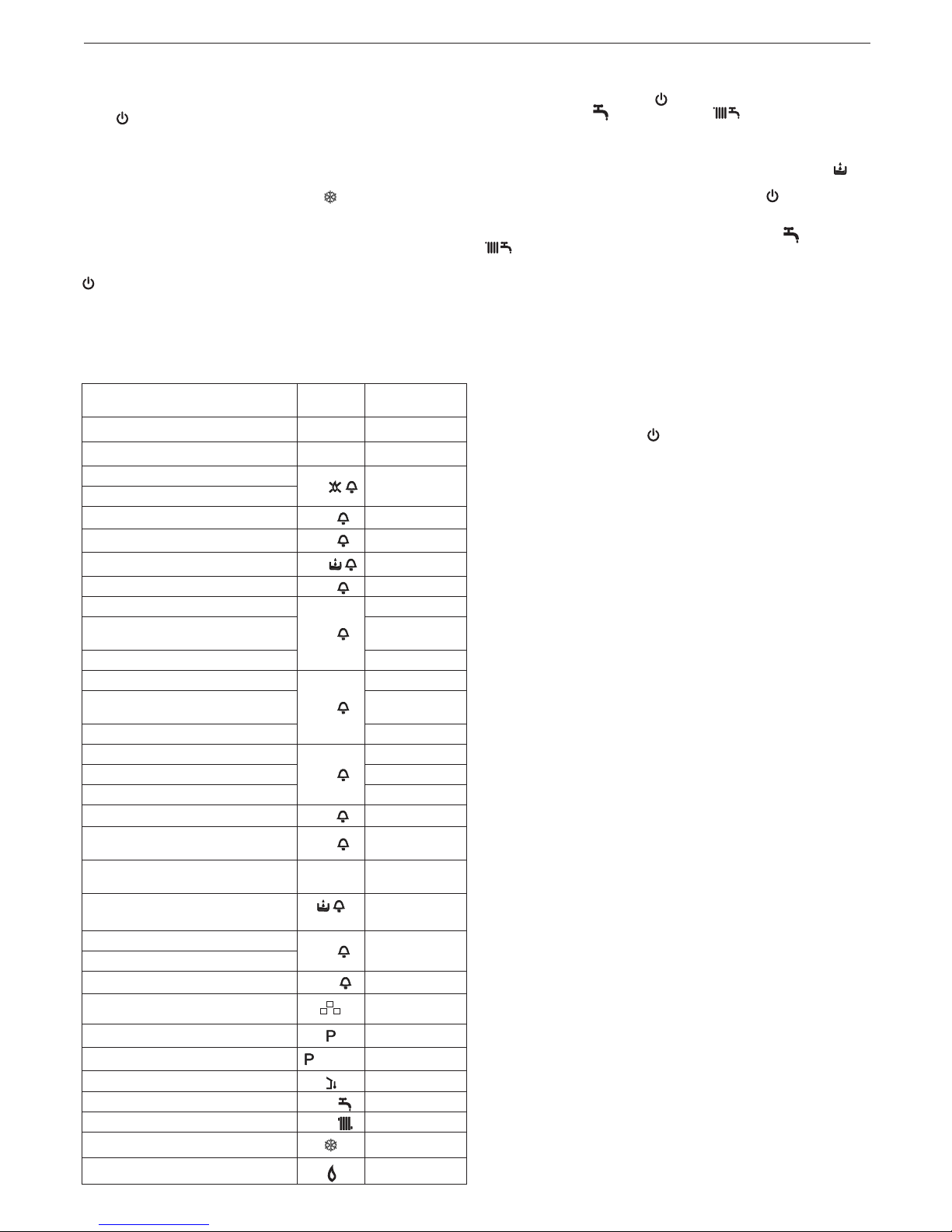
4.3 Light signals and faults
BOILER STATUS
DISPLAY
TYPES OF
ALARMS
Off status (OFF) OFF None
Stand-by - Signal
ACF alarm lockout module
A01
Denitive lockout
ACF electronics fault alarm
Limit thermostat alarm
A02
Denitive lockout
Tacho fan alarm
A03
Denitive lockout
Water pressure switch alarm
A04
Denitive lockout
NTC domestic water fault A06 Signal
NTC heating outlet fault
A07
Temporary stop
Heating outlet probe overtemperature
Temporary then
denitive
Outlet/return line probe differential
alarm
Denitive lockout
NTC heating return line fault
A08
Temporary stop
Heating return line probe overtemperature
Temporary then
denitive
Outlet/return line probe differential
alarm
Denitive lockout
Cleaning the primary heat exchan-
ger
A09
Signal
NTC ue gases fault Temporary stop
Flue gases probe overtemperature Denitive lockout
False ame
A11
Temporary stop
Low temperature system thermostat
alarm
A77
Temporary stop
Temporary pending ignition
80°C
ashing
Temporary stop
Water pressure switch intervention
ashing
Temporary stop
Calibration service
ADJ
Signal
Calibration installer
Chimney sweep
ACO
Signal
Vent cycle Signal
Preheating active function Signal
Preheating heat request
ashing
Signal
External probe presence Signal
Domestic water heat request 60°C
Signal
Heating heat request 80°C
Signal
Antifreeze heat request Signal
Flame present Signal
To restore operation (deactivate alarms):
Faults A 01-02-03
Position the function selector to (OFF), wait 5-6 seconds then set it to
the required position (summer mode) or (winter mode).
If the reset attempts do not reactivate the boiler, contact the Technical Assistance Service.
Fault A04
In addition to the fault code, the digital display shows the symbol .
Check the pressure value indicated by the water gauge: if it is less than 0.3
bar, position the function selector to (OFF) and adjust the lling tap until
the pressure reaches a value between 1 and 1.5 bar. Then position the mode
selector to the desired position (summer) or (winter). The boiler will
perform one purge cycle lasting approximately 2 minutes. If pressure drops
are frequent, request the intervention of the Technical Assistance Service.
Fault A06
The boiler operates normally but cannot reliably maintain a constant domestic hot water temperature, which remains set at around 50°C. Contact
the Technical Assistance Service.
Fault A07 - A08
Contact the Technical Assistance Service.
Fault A09
Position the function selector to (OFF), wait 5-6 seconds then set it to
the required position (summer mode) or (winter mode). If the reset attempts
do not reactivate the boiler, request the intervention of the Technical Assistance Service.
Fault A09
The boiler is equipped with an auto-diagnostic system which, based on the
total number of hours in certain operating conditions, can signal the need
to clean the primary exchanger (ue gas meter >2,500). Once the cleaning
operation has been completed, using the special kit supplied as an accessory, the total hour meter will need to be reset to zero as follows:
- switch off the power supply
- remove the housing
- loosen the xing screw then turn the instrument panel
- loosen the xing screws on the cover (F) to access the terminal board (g. 16)
- while the boiler is powered up, using a small screwdriver included, press
the CO button (g. 26) for at least 4 seconds, to check the meter has
been reset, power down then power up the boiler; the meter reading is
shown on the monitor after the “-C-” sign.
Live electrical parts (230 V AC).
Note: the meter resetting procedure should be carried out after each indepth cleaning of the primary exchanger or if this latter is replaced. To
check the status of the total hour meter, multiply the reading by 100 (e.g.
reading of 18 = 1800 total hours; reading of 1 = 100 total hours).
The boiler continues to operate normally even when the alarm is activated.
Fault A77
This is an automatic-reset fault, if the boiler does not restart, contact the
Technical Assistance Service.
4.4 Boiler conguration
There is a series of jumpers (JPX) available on the electronic board which
enable the boiler to be congured.
To access the board, proceed as follows:
- turn off the main switch on the system
- loosen the xing screws on the housing, move the base of the housing
forwards and then upwards to unhook it from the chassis
- undo the xing screws (E) from the instrument panel (g. 14)
- loosen the screws (F - g. 16) to remove the cover of the terminal board
(230V).
JUMPER JP7 - g. 38:
preselection of the most suitable heating temperature adjustment eld according to the installation type.
Jumper not inserted - standard installation
Standard installation 40-80°C
Jumper inserted - oor installation
Floor installation 20-45°C.
In the manufacturing phase, the boiler is congured for standard installations.
JP1
Calibration (see paragraph on “Adjustments”)
JP2 Reset heating timer
JP3 Calibration (see paragraph on “Adjustments”)
JP4 Absolute domestic hot water thermostat selector
JP5 Do not use
JP6 Enable night-time compensation function and continuous pump (only
with external sensor connected)
Page 10

10
CIAO GREEN C.S.I.
JP7 Enable management of low temperature/standard installations (see
above)
JP8 Do not use
4.5 Setting the thermoregulation (graphs 1-2-3)
The thermoregulation only operates with the external sensor connected;
once installed, connect the external sensor (accessory available on request)
to the special terminals provided on the boiler terminal board (g. 5).
This enables the THERMOREGULATION function.
Selecting the compensation curve
The compensation curve for heating maintains a theoretical temperature of
20°C indoors, when the external temperature is between +20°C and -20°C.
The choice of the curve depends on the minimum external temperature
envisaged (and therefore on the geographical location), and on the delivery
temperature envisaged (and therefore on the type of system). It is carefully
calculated by the installer on the basis of the following formula:
envisaged delivery T. - Tshift
KT=
20- min. envisaged external T.
Tshift = 30°C standard installations
25°C oor installations
If the calculation produces an intermediate value between two curves, you
are advised to choose the compensation curve nearest the value obtained.
Example: if the value obtained from the calculation is 1,3 this is between
curve 1 and curve 1,5. Choose the nearest curve, i.e. 1,5.
Select the KT using trimmer P3 on the board (see multiwire wiring diagram).
To access P3:
- remove the housing,
- loosen the xing screw on the instrument panel
- turn the instrument panel towards you
- loosen the xing screws on the terminal board cover
- unhook the board casing.
Live electrical parts (230 V AC).
The KT values which can be set are as follows:
standard installation: 1,0-1,5-2,0-2,5-3,0
oor installation 0,2-0,4-0,6-0,8
and these are displayed for approximately 3 seconds after rotation of the
trimmer P3.
TYPE OF HEAT REQUEST
Boiler connected to room thermostat (JUMPER 6 not inserted)
The heat request is made by the closure of the room thermostat contact,
while the opening of the contact produces a switch-off. The delivery temperature is automatically calculated by the boiler, although the user may
modify the boiler settings. Using the interface to modify the HEATING, you
will not have the HEATING SET-POINT value available, but a value that you
can set as preferred between 15 and 25°C. The modication of this value
will not directly modify the delivery temperature, but will automatically affect
the calculation that determines the value of that temperature, altering the
reference temperature in the system (0 = 20°C).
Boiler connected to a programmable timer (JUMPER JP6 inserted)
With the contact closed, the heat request is made by the delivery sensor, on
the basis of the external temperature, to obtain a nominal indoor temperature on DAY level (20°C). With the contact open, the boiler is not switched
off, but the weather curve is reduced (parallel shift) to NIGHT level (16°C).
This activates the night-time function. The delivery temperature is automatically calculated by the boiler, although the user may modify the boiler settings. Using the interface to modify the HEATING, you will not have the
HEATING SET-POINT value available, but a value that you can set as preferred between 25 and 15°C. The modication of this value will not directly
modify the delivery temperature, but will automatically affect the calculation
that determines the value of that temperature, altering the reference temperature in the system (0 = 20°C for DAY level, and 16°C for NIGHT level).
4.6 Adjustments
The boiler has already been adjusted by the manufacturer during production. If the adjustments need to be made again, for example after extraordinary maintenance, replacement of the gas valve, or conversion from methane gas to LPG, observe the following procedures.
The adjustment of the maximum and minimum output, and of the maximum
and minimum heating and of slow switch-on, must be made strictly in the
sequence indicated, and only by qualied personnel only:
- disconnect the boiler from the power supply
- turn the heating water temperature selector to its maximum
- loosen the xing screws (E) on the instrument panel (g. 14)
- lift then turn the instrument panel towards you
- loosen the xing screws on the cover (F) to access the terminal board (g. 16)
- insert the jumpers JP1 and JP3 (g. 40)
- power up the boiler.
The display shows ADJ for approximately 4 seconds, next change the following parameters:
1. Domestic hot water/absolute maximum
2. Minimum
3. Heating maximum
4. Slow switch-on
as follows:
- turn the heating water temperature selector to set the required value
- press the CO button using a small screwdriver included (g. 26) and then
skip to the calibration of the next parameter.
Live electrical parts (230 V AC).
The following icons light up on the monitor:
1. during domestic hot water/absolute maximum calibration
2. during minimum calibration
3. during heating maximum calibration
4. during slow switch-on calibration
End the procedure by removing jumpers JP1 and JP3 to store these set values in the memory. The function can be ended at any time without storing
the set values in the memory and retaining the original values as follows:
- remove jumpers JP1 and JP3 before all 4 parameters have been set
- set the function selector to (OFF/RESET)
- cut the power supply 15 minutes after it is connected.
Calibration can be carried out without powering up the boiler.
By turning the heating selection knob, the monitor automatically
shows the number of rotations, expressed in hundreds (e.g. 25 =
2,500 rpm).
For 3CEp installations with dedicated accessory, it is necessary
change the setting of minimum fan speed according the accessory
instructions.
The function for visualizing the setting parameters is activated by the function selector in summer and in winter, by pressing the CO button on the
circuit board, either with or without request for heat. This function cannot be
activated when connected to a remote control. Upon activating the function
the setting parameters are visualized in the order given below, each for 2
seconds. Each parameter is displayed together with its corresponding icon
and fan rotation speed measured in hundreds
1. Maximum
2. Minimum
3. Max. heating
4. Slow ignition P
5. Max. preset heating
GAS VALVE CALIBRATION
- Connect the boiler to the power supply
- Open the gas tap
- Set the function selector to (OFF/RESET) (monitor off)
- Loosen the screws (E), remove the housing, then lower the instrument
panel towards you (g. 14)
- Loosen the xing screws on the cover (F) to access the terminal board
(g. 16)
- Using a small screwdriver included, press the CO button (g. 26).
Live electrical parts (230 V AC).
- Wait for burner ignition.
The display shows “ACO”. The boiler operates at maximum heat output.
The “combustion analysis” function remains active for a limited time (15
min); if a delivery temperature of 90°C is reached, the burner is switched
off. It will be switched back on when this temperature drops below 78°C.
- Insert the analyser probe in the ports provided in the air distribution box,
after removing the screws from the cover (g. 41)
- Press the “combustion analysis” button a second time to reach the number of rotations corresponding to the maximum domestic hot water output
(table 1).
- Check the CO2 value: (table 3) if the value does not match the value
given in the table, use the gas valve maximum adjustment screw
- Press the “combustion analysis” button a third time to reach the number
of rotations corresponding to the minimum output (table 2).
- Check the CO2 value: (table 4) if the value does not match the value
given in the table, use the gas valve minimum adjustment screw
- To exit the “combustion analysis” function, turn the control knob
- Remove the ue gas probe and ret the plug
- Close the instrument panel and ret the housing.
The “combustion analysis” function is automatically deactivated if the board
triggers an alarm. In the event of a fault during the combustion analysis
cycle, carry out the reset procedure.
Page 11

11
ENGLISH
table 1
MAXIMUM NUMBER OF
FAN ROTATIONS
METHANE
GAS (G20)
LIQUID GAS
(G31)
25 C.S.I. heating - DHW 49 - 61 49 - 61 rpm
29 C.S.I. heating - DHW 53 - 62 52 - 60 rpm
table 2
MINIMUM NUMBER OF
FAN ROTATIONS
METHANE
GAS (G20)
LIQUID GAS
(G31)
14 14 rpm
table 3
Max. CO2
METHANE
GAS (G20)
LIQUID GAS
(G31)
9,0 10,5 %
table 4
Min. CO2
METHANE
GAS (G20)
LIQUID GAS
(G31)
9,5 10,5 %
table 5
SLOW IGNITION
METHANE
GAS (G20)
LIQUID GAS
(G31)
40 40 rpm
4.7 Gas conversion (g. 42-43)
Gas conversion from one family of gases to another can also be easily
performed when the boiler is installed.
This operation must be carried out by professionally qualied personnel.
The boiler is designed to operate with methane gas (G20) according to the
product label.
It is possible to convert the boiler to propane gas, using the special kit.
For disassembly, refer to the instructions below:
- switch off the power supply to the boiler and close the gas tap
- remove in sequence: housing and air distribution box cover
- remove the xing screw from the instrument panel
- unhook and turn the instrument panel forwards
- remove the gas valve (A)
- remove the nozzle (B) inside the gas valve and replace it with the nozzle
from the kit
- ret the gas valve
- remove the silencer from the mixer
- open the two half-shells by prising apart the corresponding hooks (C)
- replace the air diaphragm (D) in the silencer
- ret the air distribution box cover
- re-power the boiler and turn on the gas tap
Adjust the boiler as described in the chapter “Adjustments” with reference
to the information on LPG.
Conversion must be carried out by qualied personnel.
Once the conversion is complete, afx the new identication
label supplied in the kit.
4.8 Checking the combustion parameters
- Position the function selector on to switch off the boiler
- Turn the DHW temperature selector on .
Wait until the ignition of the burner (about 6 seconds). The display shows
“ACO”, the boiler operates at full power heating.
- Remove the screw C and the cover E on the air box (g. 41).
- Insert the probes of the analyzer in the positions provided on the air box.
The ue gas analysis probe must be fully inserted as far as
possible.
- Check that the CO2 values match those given in the table, if the value
shown is different, change it as indicated in the chapter entitled “Gas
valve calibration”.
Max. CO2
METHANE
GAS (G20)
LIQUID GAS
(G31)
9,0 10,5 %
Min. CO2
METHANE
GAS (G20)
LIQUID GAS
(G31)
9,5 10,5 %
- Perform the combustion check.
- Check the ue combustion.
The “combustion analysis” remains active for a time limit of 15 min; in the
event it is reached in a ow temperature of 90 °C the burner shutdown.
It will turn back when this temperature falls below 78 °C.
If you wish to stop the process turn the hot water temperature in the area
between the “+” and “-”.
Then:
- remove the analyser probe and close the sockets for combustion analysis with the special screw
- close the instrument panel and ret the housing.
5 - MAINTENANCE
The appliance must be systematically controlled at regular intervals to
make sure it works correctly and efciently and conforms to legislative provisions in force.
The frequency of controls depends on the conditions of installation and
usage, it being anyhow necessary to have a complete check carried out
by authorized personnel from the Technical Assistance Service every year.
- Check and compare the boiler’s performance with the relative specications. Any cause of visible deterioration must be immediately identied
and eliminated.
- Closely inspect the boiler for signs of damages or deterioration, particularly with the drainage and aspiration system and electrical apparatus.
- Check and adjust – where necessary – all the burner’s parameters.
- Check and adjust – where necessary – the system’s pressure.
- Analyze combustion. Compare results with the product’s specication.
Any loss in performance must be identied and corrected by nding and
eliminating the cause.
- Make sure the main heat exchanger is clean and free of any residuals or
obstruction.
- Check and clean – where necessary – the condensation tray to make
sure it works properly.
IMPORTANT: always switch off the power to the appliance and close the
gas by the gas cock on the boiler before carrying out any maintenance and
cleaning jobs on the boiler.
Do not clean the appliance or any latter part with ammable substances
(e.g. petrol, alcohol, etc.).
Do not clean panelling, enamelled and plastic parts with paint solvents.
Panels must be cleaned with ordinary soap and water only.
The ame side of the burner is made of state-of-the-art material.
Being fragile:
- be particularly careful when handling, mounting or dismantling the burner
and adjacent components (e.g. electrodes, insulation panelling etc.)
- avoid direct contact with any cleaning appliance (e.g. brushes, aspirators, blowers, etc.).
Page 12

12
CIAO GREEN C.S.I.
This component does not need any maintenance, please do not remove it
from its housing, save where the O-ring may have to be replaced.
The manufacturer declines all responsibility in cases of damages due to
failing to observe the above.
MAINTENANCE FOR PRESSURISED COLLECTIVE CHIMNEY (3CEp)
In the event of maintenance operations on the boiler which require the ue
gas pipes to be disconnected, a cap should be placed on the open element
originating from the pressurised smoke pipe.
Failure to adhere to the guidelines provided can compromise the security
of persons and animals due to potential leakages of carbon monoxide from
the smoke pipe.
6 SERIAL NUMBER PLATE
Domestic hot water function
Heating function
Qn Nominal heat delivery
Pn Nominal heat output
Qm Reduced heat delivery
Pm Reduced heat output
IP Degree of Protection
Pmw Maximum DHW pressure
Pms Maximum heating pressure
T Temperature
ŋ Performance
D Specic ow rate
NOx NOx class
3CEp The boiler may be connected to a system operating under pressure
(3CEp) by means of a check valve/non-return valve.
0694/00
Serial N.
230 V ~ 50 Hz
NOx:
Pms = T=
η
regolata per:
set at:
calibrado:
reglat:
réglage:
engestellt auf:
Via Risorgimento 13 - 23900 Lecco (LC) Italy
SK-CZ-LT-GR-HU:
IP
RO-AT:
80-60 °C
80-60 °C
50-30 °C
Qn =
Pn =
Qm
Pm =
Pn =
DK-EE-LV:
ES-PT-SI-TR-HR:
IT:
PL:
Caldaia condensazione
Condensing boiler
Caldera de condensación
Centrala in condensatie
Chaudière
Brennwertkessel
Kocioł kondensacyjny
Qn =
Pn =
à
3CEp
Page 13

13
ENGLISH
USER GUIDE
1a GENERAL WARNINGS AND SAFETY
The instruction manual is an integral part of the product and it must therefore be kept carefully and must accompany the appliance; if the manual
is lost or damaged, another copy must be requested from the Technical
Assistance Service.
Boiler installation and any other assistance and maintenance opera-
tions must be carried out by qualied personnel according to the
provisions of local legislation.
For installation, it is advisable to contact specialised personnel.
The boiler must only be used for the application foreseen by the
manufacturer. The manufacturer shall not be liable for any damage
to persons, animals or property due to errors in installation, calibration, maintenance or due to improper use.
The safety and automatic adjustment devices must not be modied,
during the system life cycle, by the manufacturer or supplier.
This appliance produces hot water, therefore it must be connected
to a heating system and/or a domestic hot water mains, compatible
with its performance and output.
In case of water leakage, close the water supply and contact the
Technical Assistance Service immediately.
In case of absence for long periods time, close the gas supply and
switch off the electrical supply main switch. If there is a risk of frost,
drain the boiler.
From time to time check that the operating pressure of the hydraulic
system does not go below 1 bar.
In case of failure and/or malfunctioning, deactivate the appliance,
and do not try to repair or operate directly on it.
Appliance maintenance must be carried out at least once a year:
scheduling it with the Technical Assistance Service will avoid wasting
time and money
When the product reaches the end of its life it should not be disposed
of as solid urban waste but should be brought to a separated waste
collection facility.
Boiler use requires strict observation of some basic safety rules:
Do not use the appliance in any manner other than its intended
purpose.
It is dangerous to touch the appliance with wet or damp body parts
and/or when barefoot.
Under no circumstances cover the intake grids, dissipation grids and
ventilation vents in the installation room with cloths, paper or any
other material.
Do not use electrical switches, telephone or any other object that
causes sparks if there is a smell of gas. Ventilate the room by open-
ing doors and windows and close the central gas tap.
Do not place anything in the boiler.
Do not perform any cleaning operation if the appliance is not discon-
nected from the mains power supply.
Do not cover or reduce ventilation opening of the room where the
generator is installed.
Do not leave containers and inammable products in the installation
room.
Do not attempt to repair the appliance in case of failure and/or mal-
functioning.
It is dangerous to pull or twist the electric cables.
Children or unskilled persons must not use the appliance.
Do not carry out operations on sealed elements.
For better use, remember that:
- periodic external cleaning with soapy water not only improves its appearance but also preserves panelling from corrosion, extending its life cycle;
- if the wall-mounted boiler is enclosed in a hanging unit, leave at least 5
cm for ventilation and maintenance;
- installation of a room thermostat will greatly improve comfort, a more rational use of the heat and energy saving; the boiler can also be connected
to a programmable timer in order to control the switching on and off of the
appliance during the day or week.
2a SWITCHING ON THE APPLIANCE
Every time the appliance is powered up, a series of data is shown on the
display including the ue gas sensor meter reading (-C- XX) (see paragraph
4a - fault A09); the automatic purge cycle then starts, lasting around 2 min-
utes. During this phase the symbol is shown on the monitor (g. 25).
To start up the boiler it is necessary to carry out the following operations:
- power the boiler
- open the gas tap to allow the ow of fuel
- set the room thermostat to the required temperature (~20°C)
- turn the mode selector to the desired position:
Winter mode: by turning the mode selector (g. 27) within the area marked
+ and -, the boiler provides domestic hot water and heating. If there is a heat
request, the boiler switches on. The digital monitor indicates the heating
water temperature, the icon to indicate heating and the ame icon (g. 29).
If there is a domestic hot water request, the boiler switches on.
The digital display shows the hot water system temperature, the icon to
indicate the hot water supply and the ame icon (g. 30).
Adjustment of the heating water temperature
To adjust the heating water temperature, turn the knob with symbol
(g. 27) within the area marked + and -.
Adjusting heating water temperature with an external probe connected
When an external probe is connected, the value of the delivery temperature
is automatically chosen by the system which rapidly adjusts ambient temperature to the changes in external temperature.
To increase or decrease the temperature with respect to the value automatically calculated by the electronic board, turn the heating water selector
clockwise to increase and anticlockwise to decrease.
Adjustment settings range from comfort levels - 5 to + 5 which are indicated
on the digital display when the knob is turned.
Summer mode: turning the selector to the summer mode symbol (g.
28) activates the traditional domestic hot water only function.
If there is a domestic hot water request, the boiler switches on. The digital
monitor indicates the domestic hot water temperature, the icon to indicate
the hot water supply and the ame icon (g. 30).
Pre-heating (faster hot water): turning the domestic hot water temperature adjustment knob to the symbol (g. 31) activates the pre-heating
function, the monitor indicates the xed symbol. Bring the domestic hot
water temperature adjustment knob back to the required position.
This function keeps the water in the domestic hot water exchanger hot, to
reduce standby times when a request is made.
The monitor indicates the delivery temperature of the heating water or
the domestic hot water, according to the current request. During burner
ignition following a pre-heating request, the monitor indicates the ashing
symbol and the ame icon.
To deactivate the pre-heating function, rotate the domestic hot water temperature adjustment knob back to the symbol. Bring the domestic hot
water temperature adjustment knob back to the required position.
This function cannot be activated when the boiler is OFF: function selector
(g.32) to (OFF).
Adjustment of domestic hot water temperature
To adjust the domestic hot water temperature (bathrooms, shower, kitchen,
etc.), turn the knob with the symbol (g. 28) rotate clockwise to increase
the temperature and anticlockwise to reduce it.
The boiler is standby status until, after a heat request, the burner switches
on. The boiler continues to operate until the temperatures set on the boiler
are reached, or the heat request is met; after which it goes back on standby.
If the symbol (g. 34) on the control panel lights up, this means the
boiler is in temporary shutdown status (see the chapter on “Light signals
and faults”). The digital monitor indicates the fault code detected (g. 34).
Automatic Temperature Control System function (S.A.R.A.) g. 35
Setting the heating water temperature selector to the area marked “AUTO”,
activates the automatic temperature control system: according to the temperature set on the room thermostat and the time taken to reach it, the
boiler varies automatically the heating water temperature reducing the operating time, allowing greater ease of operation and energy saving.
Reset function
To restore operation, set the function selector to (g. 32), wait 5-6 seconds
then set the function selector to the required position.
N.B. If the attempt to reset the appliance does not activate operation, contact the Technical Assistance Service.
Page 14
14
CIAO GREEN C.S.I.
3a SWITCHING OFF
Temporary switch-off
In case of absence for short periods of time, set the mode selector (g.
32) to (OFF).
In this way (leaving the electricity and fuel supplies enabled), the boiler is
protected by:
Anti-frost device: when the temperature of the water in the boiler falls below
5°C, the circulator and, if necessary, the burner are activated at minimum
output levels to bring the water temperature back to the values for safety
(35°C). During the anti-frost cycle, the symbol (g. 36) appears on the
digital monitor.
Circulator anti-blocking function: an operation cycle is activated every
24 hours.
Switching off for long periods
In case of absence for long periods of time, set the mode selector (g. 32) to
(OFF). Turn the main system switch OFF. Close the fuel and water taps
of the heating and domestic hot water system. In this case, anti-frost device
is deactivated: drain the systems, in case of risk of frost.
4a LIGHT SIGNALS AND FAULTS
The operating status of the boiler is shown on the digital display, below is a
list of the types of displays.
BOILER STATUS
DISPLAY
TYPES OF
ALARMS
Off status (OFF) OFF None
Stand-by - Signal
ACF alarm lockout module
A01
Denitive lockout
ACF electronics fault alarm
Limit thermostat alarm
A02
Denitive lockout
Tacho fan alarm
A03
Denitive lockout
Water pressure switch alarm
A04
Denitive lockout
NTC domestic water fault A06 Signal
NTC heating outlet fault
A07
Temporary stop
Heating outlet probe overtemperature
Temporary then
denitive
Outlet/return line probe differential alarm Denitive lockout
NTC heating return line fault
A08
Temporary stop
Heating return line probe overtempera-
ture
Temporary then
denitive
Outlet/return line probe differential alarm Denitive lockout
Cleaning the primary heat exchanger
A09
Signal
NTC ue gases fault Temporary stop
Flue gases probe overtemperature Denitive lockout
False ame
A11
Temporary stop
Low temperature system thermostat
alarm
A77
Temporary stop
Temporary pending ignition
80°C
ashing
Temporary stop
Water pressure switch intervention
ashing
Temporary stop
Calibration service
ADJ
Signal
Calibration installer
Chimney sweep
ACO
Signal
Vent cycle Signal
Preheating active function Signal
Preheating heat request
ashing
Signal
External probe presence Signal
Domestic water heat request 60°C
Signal
Heating heat request 80°C
Signal
Antifreeze heat request Signal
Flame present Signal
To restore operation (deactivate alarms):
Faults A 01-02-03
Position the function selector to (OFF), wait 5-6 seconds then set it to
the required position (summer mode) or (winter mode).
If the reset attempts do not reactivate the boiler, contact the Technical Assistance Service.
Fault A04
In addition to the fault code, the digital display shows the symbol .
Check the pressure value indicated by the water gauge:
if it is less than 0.3 bar, position the function selector to OFF (g. 32) and
adjust the lling tap (C- g 17) until the pressure reaches a value between
1 and 1.5 bar.
Then position the mode selector to the desired position (summer) or
(winter).
The boiler will perform one purge cycle lasting approximately 2 minutes.
If pressure drops are frequent, request the intervention of the Technical
Assistance Service.
Fault A06
The boiler operates normally but cannot reliably maintain a constant domestic hot water temperature, which remains set at around 50°C. Contact
the Technical Assistance Service.
Fault A07
Contact the Technical Assistance Service.
Fault A08
Contact the Technical Assistance Service.
Fault A09
Position the function selector to (OFF), wait 5-6 seconds then set it to the
required position (summer mode) or (winter mode).
If the reset attempts do not reactivate the boiler, request the intervention of
the Technical Assistance Service.
Fault A09
Contact the Technical Assistance Service.
Fault A77
This is an automatic-reset fault, if the boiler does not restart, contact the
Technical Assistance Service.
Page 15

15
ENGLISH
DESCRIPTION CIAO GREEN 25 C.S.I. CIAO GREEN 29 C.S.I.
Heating Heat input kW 20,00 25,00
kcal/h 17.200 21.500
Maximum heat output (80/60°) kW 19,50 24,45
kcal/h 16.770 21.027
Maximum heat output (50°/30°) kW 20,84 26,23
kcal/h 17.922 22.554
Minimum heat input kW 5,00 6,00
kcal/h 4.300 5.160
Minimum heat output (80°/60°) kW 4,91 5,90
kcal/h 4.218 5.072
Minimum heat output (50°/30°) kW 5,36 6,40
kcal/h 4.610 5.506
DHW Heat input kW 25,00 29,00
kcal/h 21.500 24.940
Maximum heat output (*) kW 25,00 29,00
kcal/h 21.500 24.940
Minimum heat input kW 5,00 6,00
kcal/h 4.300 5.160
Minimum heat output (*) kW 5,00 6,00
kcal/h 4.300 5.160
(*) average value of various DHW operating conditions
Useful efciency Pn max - Pn min (80°/60°) % 97,5-98,1 97,8-98,3
Efciency 30% (47° return) % 102,2 102,0
Combustion performance % 97,9 98,1
Useful efciency Pn max - Pn min (50°/30°) % 104,2-107,2 104,9-106,7
Efciency 30% (30° return) % 108,9 108,4
Electric power W 83 90
Circulator electric power (1.000 l/h) W 40 40
Category II2H3P II2H3P
Country of destination - Power supply voltage V - Hz 230-50 230-50
Degree of Protection IP X5D X5D
Pressure drops on ue with burner on % 2,10 1,93
Pressure drops on ue with burner off % 0,06 0,04
Heating operation
Pressure - maximum temperature bar 3-90 3-90
Minimum pressure for standard operation bar 0,25-0,45 0,25-0,45
Selection eld of heating water temperature °C 20/45-40/80 20/45-40/80
Pump: maximum head available mbar 300 300
for system capacity l/h 800 800
Membrane expansion tank l 8 8
Expansion tank pre-charge bar 1 1
DHW operation
Maximum pressure bar 6 6
Minimum pressure bar 0,15 0,15
Hot water quantity with ∆t 25°C l/min 14,3 16,6
with ∆t 30°C l/min 11,9 13,9
with ∆t 35°C l/min 10,2 11,9
DHW minimum output l/min 2 2
Selection eld of DHW temperature °C 37-60 37-60
Flow regulator l/min 10 12
Gas pressure
Methane gas nominal pressure (G20) mbar 20 20
LPG liquid gas nominal pressure (G31) mbar 37 37
Hydraulic connections
Heating input - output Ø 3/4” 3/4”
DHW input-output Ø 1/2” 1/2”
Gas input Ø 3/4” 3/4”
TECHNICAL DATA
Page 16

16
CIAO GREEN C.S.I.
Multigas table
DESCRIPTION
CIAO GREEN 25 C.S.I. CIAO GREEN 29 C.S.I.
Boiler dimensions
Height mm 715 715
Width mm 405 405
Depth of housing mm 250 250
Boiler weight kg 29 28
Flow rate (G20)
Air capacity Nm3/h 24,908 31,135 31,135 36,116
Flue gas capacity Nm3/h 26,914 33,642 33,642 39,025
Mass ow of ue gas (max-min) gr/s 9,025-2,140 11,282-2,140 11,282-2,568 13,087-2,568
Flow rate (G31)
Air capacity Nm3/h 24,192 30,240 30,240 35,078
Flue gas capacity Nm3/h 24,267 31,209 31,209 36,203
Mass ow of ue gas (max-min) gr/s 8,410-2,103 10,513-2,103 10,513-2,523 12,195-2,523
Fan performance
Residual head of concentric pipes 0.85m Pa 30 25
Residual head of separate pipes 0.5m Pa 90 100
Residual head of boiler without pipes Pa 100 110
Concentric ue gas discharge pipes
Diameter mm 60-100 60-100
Maximum length m 5,85 4,85
Drop due to insertion of a 45°/90° bend m
1,3/1,6 1,3/1,6
Hole in wall (diameter) mm 105 105
Concentric ue gas discharge pipes
Diameter mm 80-125 80-125
Maximum length m 15,3 12,8
Losses for a 45°/90° bend m 1/1,5 1/1,5
Hole in wall (diameter) mm 130 130
Separate ue gas discharge pipes
Diameter mm 80 80
Maximum length m 45+45 40+40
Losses for a 45°/90° bend m 1/1,5 1/1,5
Installation B23P–B53P
Diameter mm 80 80
Maximum length of drainage pipe m 70 65
NOx class class 5 class 5
Emission values at max. and min. rate of gas G20*
Maximum - Minimum CO s.a. less than ppm 180 - 20 160 - 20
CO2 %
9,0 - 9,5 9,0 - 9,5
NOx s.a. lower than ppm 30 - 20 35 - 25
Flue gas temperature °C 65 - 58 63 - 58
* Check performed with concentric pipe ø 60-100, length 0.85m - water temperature 80-60°C
DESCRIPTION
Methane gas
(G20)
Propane
(G31)
Lower Wobbe index (at 15°C-1013 mbar) MJ/m3S 45,67 70,69
Net Caloric Value MJ/m3S 34,02 88
Supply nominal pressure mbar (mm W.C.) 20 (203,9) 37 (377,3)
Supply minimum pressure mbar (mm W.C.) 10 (102,0)
Diaphragm (number of holes) Number 1 1
25 C.S.I. 29 C.S.I. 25 C.S.I. 29 C.S.I.
Diaphragm (diameter of holes) mm 4,8 5,6 3,8 4,3
Silencer diaphragm (diameter) mm 31 - 27 29
Heating maximum gas capacity Sm3/h 2,12 2,64
kg/h 1,55 1,94
DHW maximum gas capacity Sm3/h 2,64 3,07
kg/h 1,94 2,25
Heating minimum gas capacity Sm3/h 0,53 0,63
kg/h 0,39 0,47
DHW minimum gas capacity Sm3/h 0,53 0,63
kg/h 0,39 0,47
Number of fan rotations with slow switch-on rpm 4.000 4.000 4.000 4.000
Maximum number of fan rotations (heating) rpm 4.900 5.300 4.900 5.200
Maximum number of fan rotations (DHW) rpm 6.100 6.200 6.100 6.000
Minimum number of fan rotations (heating) rpm 1.400 1.400 1.400 1.400
Minimum number of fan rotations (DHW) rpm 1 .400 1.400 1.400 1.400
Page 17

17
ENGLISH
Parameter Symbol
CIAO GREEN 25
C.S.I.
CIAO GREEN 29
C.S.I.
Unit
Seasonal space heating energy efciency class - A A Water heating energy efciency class - A A Rated heat output Pnominal 20 24 kW
Seasonal space heating energy efciency ηs 93 93 %
Useful heat output
At rated heat output and high-temperature regime (*) P4 19,5 24,5 kW
At 30% of rated heat output and low-temperature
regime (**)
P1 6,5 8,1 kW
Useful efciency
At rated heat output and high-temperature regime (*) η4 88,1 88,2 %
At 30% of rated heat output and low-temperature
regime (**)
η1 98,1 97,6 %
Auxiliary electricity consumption
At full load elmax 29,0 38,0 W
At part load elmin 10,4 13,1 W
In Stand-by mode PSB 2,4 2,4 W
Other parameters
Stand-by heat loss Pstby 40,0 35,0 W
Pilot ame energy consumption Pign - - W
Annual energy consumption QHE 38 47 GJ
Sound power level, indoors LWA 53 56 dB
Emissions of nitrogen oxides NOx 20 23 mg/ kWh
For combination heaters
Declared load prole XL XL
Water heating energy efciency ηwh 85 85 %
Daily electricity consumption Qelec 0,109 0,120 kWh
Daily fuel consumption Qfuel 22,920 23,021 kWh
Annual electricity consumption AEC 24 26 kWh
Annual fuel consumption AFC 17 17 GJ
(*) High-temperature regime means 60 °C return temperature at heater inlet and 80 °C feed temperature at heater outlet.
(**) Low temperature means for condensing boilers 30 °C, for low-temperature boilers 37 °C and for other heaters 50 °C return
temperature (at heater inlet).
Page 18

18
CIAO GREEN C.S.I.
MANUAL DEL INSTALADOR
ES
ESPAÑOL
1 - ADVERTENCIAS Y DISPOSITIVOS DE SE-
GURIDAD
Las calderas producidas en nuestros establecimientos se fabrican prestando
atención a cada uno de los componentes de manera tal de proteger tanto
al usuario como al instalador contra eventuales accidentes. Se aconseja al
personal cualicado, después de cada intervención efectuada en el producto,
que preste particular atención a las conexiones eléctricas, sobre todo por
lo que se reere a la parte no cubierta de los conductores, que de ninguna
forma tiene que sobresalir de la bornera, evitando de esta forma el posible
contacto con las partes vivas de dicho conductor.
El presente manual de instrucciones, junto con el del usuario, forma
parte integrante del producto: hay que comprobar que forme parte
del equipamiento del aparato, incluso en el caso de cesión a otro
propietario o usuario, o bien de traslado a otra planta. En el caso de
que se dañe o se pierda, hay que solicitar otro ejemplar al Servicio
Técnico de Asistencia de la zona.
La instalación de la caldera y cualquier otra intervención de asistencia
y de mantenimiento, deben ser realizadas por personal cualicado
según las indicaciones de las leyes vigentes.
Se aconseja al instalador que instruya al usuario sobre el funciona-
miento del aparato y sobre las normas fundamentales de seguridad.
Esta caldera debe destinarse al uso para el cual ha sido expresa-
mente fabricada. Se excluye cualquier responsabilidad contractual
y extracontractual del fabricante por daños causados a personas,
animales o cosas, por errores de instalación, regulación, mantenimiento y por usos inadecuados
Después de haber quitado el embalaje, se debe comprobar que
el contenido esté íntegro y completo. En el caso de que no exista
correspondencia, ponerse en contacto con el revendedor donde se
ha adquirido el aparato.
Al nal de la vida útil, no eliminar el producto como un residuo sólido
urbano, sino enviarlo a un centro de recogida selectiva.
El conducto de evacuación de la válvula de seguridad del aparato
se debe conectar a un adecuado sistema de recogida y descarga.
El fabricante del aparato no es responsable de los eventuales daños
causados por la intervención de la válvula de seguridad.
Eliminar los elementos de embalaje en los contenedores adecuados
en los centros de recogida especícos.
Los residuos deben eliminarse sin causar peligro a la salud del hom-
bre y sin utilizar procedimientos o métodos que pudieran producir
daños al medio ambiente.
Durante la instalación, se debe informar al usuario que:
- en el caso de pérdidas de agua, se debe cerrar la alimentación
hídrica y avisar inmediatamente al Servicio Técnico de Asistencia
- debe controlar periódicamente que la presión de funcionamiento
de la instalación hidráulica sea superior a 1 bar. En caso de ser
necesario, restablecer la presión como se indica en el apartado
“Llenado de la instalación”
- en caso de no utilizar la caldera durante un período prolongado,
se recomienda efectuar las siguientes operaciones:
- colocar el interruptor principal del aparato y el general de la instalación en “apagado”
- cerrar los grifos del combustible y del agua de la instalación térmica
- vaciar la instalación térmica si hay peligro de heladas.
Desde el punto de vista de la seguridad se debe recordar que:
No se aconseja que los niños o las personas incapacitadas usen la
caldera sin asistencia
Es peligroso accionar dispositivos o aparatos eléctricos, tales como
interruptores, electrodomésticos, etc., si se advierte olor a combustible o de combustión. En el caso de pérdidas de gas, airear el local,
abriendo puertas y ventanas; cerrar el grifo general del gas; solicitar
la inmediata intervención de personal profesionalmente cualicado
del Servicio Técnico de Asistencia.
No tocar la caldera si se está descalzo o con partes del cuerpo
mojadas o húmedas
Antes de efectuar las operaciones de limpieza, desconectar la
caldera de la red de alimentación eléctrica colocando el interruptor
bipolar de la instalación y el principal del panel de mandos en “OFF”
Está prohibido modicar los dispositivos de seguridad o de regulación
sin la autorización o las indicaciones del fabricante.
No estirar, dividir o torcer los cables eléctricos que sobresalgan de la
caldera, aunque esté desconectada de la red de alimentación eléctrica.
Evitar tapar o reducir dimensionalmente las aperturas de aireación
del local de instalación.
No dejar contenedores y sustancias inamables en el local donde
esté instalado el aparato.
No dejar los elementos del embalaje al alcance de los niños
Se prohíbe obstruir el conducto de evacuación de agua de condensación.
2 - DESCRIPCIÓN
Ciao Green C.S.I. es una caldera mural de condensación de tipo C para
calefacción y producción de agua caliente sanitaria: de acuerdo al accesorio de evacuación de humos utilizado, se clasica en las categorías B23P,
B53P, C13, C23, C33, C43, C53, C63, C83, C93, C13x, C33x, C43x, C53x,
C63x, C83x, C93x. En la conguración B23P, B53P (cuando se instala en
el interior) el aparato no puede ser instalado en locales destinados a dormitorios, baños, duchas o en donde existan chimeneas abiertas sin aujo
de aire propio. El local donde se instalará la caldera deberá tener una ventilación adecuada. En la conguración C, el aparto puede ser instalado en
cualquier tipo de local y no existe ninguna limitación debida a las condiciones de aireación y al volumen del local.
3 - INSTALACIÓN
3.1 Normas de instalación
La instalación deberá ser realizada por personal cualicado y en conformidad con las normativas locales.
UBICACIÓN
La caldera está equipada con protecciones que garantizan su correcto funcionamiento con un rango de temperaturas de 0°C a 60°C.
Para poder aprovechar las protecciones, el aparato debe poder encenderse,
por lo que se desprende que cualquier situación de bloqueo (por ej., falta de
gas o de alimentación eléctrica, o bien una intervención de un dispositivo de
seguridad) desactiva las protecciones. Si se quita la alimentación eléctrica
de la máquina durante períodos prolongados en zonas donde se pueden
producir temperaturas inferiores a los 0°C y no se desea vaciar la instalación
de calefacción, para la protección antihielo de la misma se recomienda introducir un anticongelante de marca reconocida en el circuito principal. Respetar estrictamente las instrucciones del fabricante con respecto al porcentaje
de líquido anticongelante de acuerdo a la temperatura mínima a la cual se
desea preservar el circuito de la máquina, la duración y la eliminación del
líquido. Para la parte sanitaria, se recomienda vaciar el circuito. Los materiales con los cuales están realizados los componentes de las calderas resisten
los líquidos anticongelantes a base de glicol de etileno.
DISTANCIAS MÍNIMAS
Para poder permitir el acceso al interior de la caldera para realizar las normales operaciones de mantenimiento, se deben respetar los espacios mínimos previstos para la instalación (g. 9).
Para colocar correctamente el aparato, se debe tener en cuenta que:
- no se debe colocar sobre una cocina u otro aparato de cocción
- está prohibido dejar sustancias inamables en el local donde esté instalada
la caldera
- las paredes sensibles al calor (por ejemplo las de madera) deben protegerse con un aislamiento apropiado.
IMPORTANTE
Antes de la instalación, se aconseja lavar cuidadosamente todas las tuberías de la instalación para remover eventuales residuos que podrían comprometer el funcionamiento correcto del aparato.
Conectar el colector de descarga a un sistema de evacuación adecuado (para
los detalles remitirse al capítulo 3.5). El circuito de agua sanitaria no necesita de
una válvula de seguridad, pero debe asegurarse que la presión del acueducto
no supere los 6 bar. Si no existe certeza sobre la presión, se deberá instalar un
reductor de presión. Antes del encendido, asegurarse de que la caldera esté preparada para funcionar con el gas disponible; esto se comprueba por la leyenda
del embalaje y por la etiqueta adhesiva que indica el tipo de gas. Es muy importante destacar que en algunos casos, las chimeneas adquieren presión y por lo
tanto las uniones de los diferentes elementos deben ser herméticas.
En algunas partes del manual se utilizan estos símbolos:
ATENCIÓN = para acciones que requieren especial cuidado y preparación
apropiada
PROHIBIDO = para acciones que absolutamente NO DEBEN ser realizadas
Page 19

19
ESPAÑOL
3.2 Limpieza de la instalación y características del agua
del circuito de calefacción
En caso de una nueva instalación o sustitución de la caldera se debe efectuar una limpieza previa de la instalación de calefacción.
Para garantizar el funcionamiento correcto del producto, después de cada
operación de limpieza, de agregado de aditivos y/o tratamientos químicos
(por ej. líquidos anticongelantes,lmantes, etc.), vericar que los parámetros en la tabla se encuentren dentro de los valores indicados.
Parámetros udm Agua circuito
calefacción
Agua
llenado
Valor PH 7÷8
-
Dureza ° F
-
15÷20
Aspecto
- límpido
3.3 Fijación de la caldera a la pared y conexiones
hidráulicas
Para jar la caldera a la pared utilizar el travesaño (g. 10) presente en el
embalaje.
La posición y la dimensión de los acoplamientos hidráulicos se indican en
detalle a continuación:
M envío calefacción 3/4”
AC salida agua sanitaria 1/2”
G conexión gas 3/4”
AF entrada agua sanitaria 1/2”
R retorno calefacción 3/4”
3.4 Instalación de la sonda exterior (g. 11)
Es fundamental que la sonda exterior funcione correctamente para que el
control climático cumpla un funcionamiento correcto.
INSTALACIÓN Y CONEXIÓN DE LA SONDA EXTERIOR
La sonda debe instalarse en una pared exterior del edicio que se desea
calentar pero respetando las siguientes indicaciones:
debe montarse en la fachada con mayor frecuencia de exposición al viento, pared situada al NORTE o NOROESTE, evitando la irradiación directa
de rayos solares; debe montarse a aproximadamente 2/3 de la altura de
la fachada; no debe situarse cerca de puertas, ventanas, evacuación del
conducto de aire o al reparo de chimeneas u otras fuentes de calor.
La conexión eléctrica a la sonda exterior se debe realizar con un cable
bipolar de 0,5 a 1 mm2 de sección, que no forma parte del suministro, con
longitud máxima de 30 metros. No es necesario respetar la polaridad del
cable que se conectará a la sonda exterior. Evitar realizar uniones en este
cable; en caso de que no puedan evitarse deberá estañarse y protegerse
convenientemente. Eventuales canalizaciones del cable de conexión deben estar separadas de los cables con tensión (230V c.a.).
FIJACIÓN EN PARED DE LA SONDA EXTERIOR
La sonda debe colocarse en una supercie lisa de la pared; en caso de
ladrillo visto o pared irregular debe preverse un área de contacto lo más lisa
posible. Desenroscar la tapa de protección superior de plástico girándola
en sentido antihorario. Identicar el lugar de jación a la pared y realizar la
perforación para el taco de expansión de 5x25.
Introducir el taco en el oricio. Extraer la tarjeta de su alojamiento.
Fijar la caja a la pared utilizando el tornillo suministrado.
Enganchar la brida y apretar el tornillo.
Desenroscar la tuerca del anillo pasacable, introducir el cable de conexión
de la sonda y conectarlo al borne eléctrico.
Por la conexión eléctrica de la sonda exterior a la caldera consultar el capítulo “Conexiones eléctricas”.
Recordar cerrar correctamente el anillo pasacable para evitar que
la humedad del aire entre a través de la abertura del mismo.
Introducir nuevamente la tarjeta en su alojamiento.
Cerrar la tapa de protección superior de plástico girándola en sentido horario. Apretar rmemente el anillo pasacable.
3.5 Recogida condensación
La instalación debe ser realizada en modo de evitar la congelación de la
condensación producida por la caldera (por ej. aislándola). Se recomienda
la instalación de un colector de evacuación especíco de polipropileno
que se puede hallar en comercios en la parte inferior de la caldera - oricio
Ø 42 - como se indica en la gura 12.
Posicionar el tubo exible de evacuación de la condensación suministrado con la caldera, conectándolo al colector (u otro dispositivo de unión
que pueda inspeccionarse) evitando crear pliegues donde la condensación
pueda estancarse y eventualmente congelarse. El fabricante no se responsabiliza por eventuales daños causados por la falta de conducción de la
condensación o por congelación de la misma. La estanqueidad de la línea
de conexión de la evacuación debe estar garantizada y adecuadamente
protegida de los riesgos de la congelación.
Antes de la puesta en servicio del aparato asegurarse de que la condensación pueda ser evacuada correctamente.
3.6 Conexión del gas
Antes de realizar la conexión del aparato a la red de gas, controlar que:
- hayan sido respetadas las normas nacionales y locales de instalación
- el tipo de gas sea aquel para el cual el aparto está preparado
- las tuberías estén limpias.
Está previsto que la canalización del gas sea externa. En el caso de que el
tubo atraviese la pared, tendrá que pasar a través del oricio central de la
parte inferior de la plantilla.
Se aconseja instalar en la línea del gas un ltro de adecuadas dimensiones,
en el caso de que la red de distribución pudiera contener partículas sólidas.
Una vez realizada la instalación, comprobar que las uniones efectuadas
sean estancas, como prevén las vigentes normas sobre la instalación
3.7 Conexión eléctrica
Para acceder a las conexiones eléctricas se deben realizar las siguientes
operaciones:
Para acceder a la bornera:
- colocar el interruptor general de la instalación en “apagado”
- desenroscar los tornillos (D) de jación de la cubierta (g. 13)
- desplazar hacia adelante y luego hacia arriba la base de la cubierta para
desengancharla del bastidor
- desenroscar el tornillo de jación (E) del panel de mandos (g. 14)
- levantar y girar el panel de mandos hacia sí mismo (g. 15)
- desenganchar la tapa de la cubierta de la tarjeta (g. 16)
- colocar el cable del T.A. (si estuviera presente).
El termostato ambiente se debe conectar como se indica en el esquema
eléctrico.
Entrada termostato ambiente con baja tensión de seguridad (24
Vdc).
La conexión a la red eléctrica debe realizarse mediante un dispositivo de
separación con apertura omnipolar de por lo menos 3,5 mm (EN 60335/1,
categoría 3). El aparato funciona con corriente alterna a 230 Volt/50 Hz,
tiene una potencia eléctrica de 83 W (25 C.S.I.) - 90 W (29 C.S.I.) y está
en conformidad con la norma EN 60335-1. Es obligatoria la conexión a una
puesta a tierra segura, de acuerdo con la Normativa vigente.
Es responsabilidad del instalador asegurar una puesta a tierra
correcta del aparato; el fabricante no responderá por eventuales
daños causados por una incorrecta realización de la puesta a tierra
o por ausencia de la misma
Se aconseja respetar la conexión fase neutro (L-N).
El conductor de tierra debe ser un par de centímetros más largos
que los demás.
La caldera puede funcionar con alimentación fase-neutro o fase-fase.
Para alimentaciones sin conexiones a tierra se debe utilizar un transformador de aislamiento con secundario anclado a tierra.
Está prohibido el uso de tubos de gas y/o agua como puesta a tierra de aparatos eléctricos. Para la conexión eléctrica utilizar el cable de alimentación suministrado en dotación. En el caso de sustituir el cable de alimentación, utilizar un
cable tipo HAR H05V2V2-F, 3x 0,75 mm2, con diámetro máx. exterior de 7 mm.
3.8 Llenado de la instalación de calefacción
Una vez efectuadas las conexiones hidráulicas, se puede seguir con el
llenado de la instalación de calefacción.
Esta operación se tiene que realizar con la instalación en frío, efectuando
las siguientes operaciones (g. 17):
- abrir dos o tres giros el tapón de la válvula inferior (A) de escape auto-
mático de aire, para purgar continuamente el aire, dejar abierto el tapón
de la válvula A
- asegurarse de que el grifo de entrada de agua fría esté abierto
- abrir el grifo de llenado (C) hasta que la presión indicada por el hidróme-
tro esté comprendida entre 1 y 1,5 bar
- cerrar el grifo de llenado.
Nota: la caldera se purga automáticamente mediante las dos válvulas de
purga automática A y E, la primera situada en el circulador y la segunda
dentro de la caja de aire. Si la fase de purga presenta dicultades, operar
como se describe en el apartado 3.11.
3.9 Vaciado de la instalación de calefacción
Antes de comenzar el vaciado cortar la alimentación eléctrica colocando el
interruptor general de la instalación en “apagado”.
Cerrar los dispositivos de interceptación de la instalación térmica
Aojar manualmente la válvula de evacuación de la instalación (D).
Page 20

20
CIAO GREEN C.S.I.
3.10 Vaciado del circuito agua sanitaria
Cada vez que exista el riesgo de heladas, el circuito agua sanitaria se debe
vaciar de la siguiente forma:
- cerrar el grifo general de la red hídrica
- abrir todos los grifos del agua caliente y fría
- vaciar los puntos más bajos.
3.11 Eliminación del aire del circuito de calefacción y de
la caldera
Durante la fase de la primera instalación o en caso de mantenimiento extraordinario, se recomienda efectuar la siguiente secuencia de operaciones:
1. Abrir dos o tres giros el tapón de la válvula inferior (A, g. 18) de esca-
pe automático de aire, para purgar continuamente el aire, dejar abierto
el tapón de la válvula A.
2. Abrir el grifo de llenado de la instalación situado en el grupo hidráulico,
esperar hasta que comience a salir agua por la válvula.
3. Suministrar electricidad a la caldera dejando cerrado el grifo del gas.
4. Activar una solicitud de calor con el termostato ambiente o con el pa-
nel de mandos a distancia en modo de que la válvula de tres vías se
posicione en calefacción.
5. Activar una solicitud de calor del siguiente modo:
abrir un grifo durante 30” cada minuto, para que la válvula de tres vías
realice ciclos de calefacción en agua sanitaria y viceversa por una
decena de veces (en esta situación la caldera entrará en alarma por
falta de gas, luego restablecerla cada vez que se deba repetir).
6. Continuar la secuencia hasta que por la salida de la válvula de escape
de aire manual únicamente salga agua y que el ujo de aire haya nalizado. Cerrar la válvula de escape de aire manual.
7. Controlar que la presión de la instalación sea la correcta (ideal 1 bar).
8. Cerrar el grifo de llenado de la instalación.
9. Abrir el grifo del gas y encender la caldera.
3.12 Evacuación de los productos de la combustión y
aspiración del aire
Para la evacuación de los productos de combustión, consultar las normativas locales. La evacuación de los productos de la combustión está asegurada por un ventilador centrífugo ubicado en el interior de la cámara de combustión y su funcionamiento correcto está constantemente controlado por la
tarjeta de control. La caldera se entrega sin el kit de evacuación de humos/
aspiración de aire, ya que pueden utilizarse los accesorios para aparatos de
cámara estanca de tiraje forzado que mejor se adecuen a las características
de las tipologías de instalación. Es indispensable para la evacuación de los
humos y para el restablecimiento del aire comburente de la caldera que se
empleen únicamente tuberías certicadas y que la conexión se realice de
manera correcta, tal como se indica en las instrucciones suministradas en
dotación con los accesorios de los humos. A una sola chimenea se pueden
conectar varios aparatos con la condición de que todos sean del tipo de
cámara estanca. La caldera es un aparato de tipo C (de cámara estanca) y
por lo tanto debe tener una conexión segura al conducto de evacuación de
humos y al de aspiración del aire comburente, ambos que desembocan en el
exterior y sin los cuales el aparato no puede funcionar.
POSIBLES CONFIGURACIONES DE LA EVACUACIÓN (g. 24)
B23P/B53P
Aspiración en el ambiente y evacuación hacia el exterior
C13-C13x Evacuación concéntrica en pared. Los tubos pueden salir de la caldera independientemente, pero las salidas tienen que ser concéntricas o estar
bastante cerca para ser sometidas a condiciones de viento similares (en 50 cm).
C23 Evacuación concéntrica en chimenea común (aspiración y evacuación
en la misma chimenea).
C33-C33x Evacuación concéntrica en techo. Salidas como en C13
C43-C43x Conductos de evacuación y aspiración en chimeneas comunes
separados, pero sometidos a similares condiciones de viento.
C53-C53x Conductos de evacuación y aspiración separados, en la pared o en
el techo, en cualquier caso en zonas con presiones diferentes. El conducto de
evacuación y el de aspiración no se deben instalar nunca en paredes opuestas.
C63-C63x Conducto de evacuación y aspiración realizados con tubos comercializados y certicados de manera separada (1856/1).
C83-C83x Conducto de evacuación en chimenea individual o común y aspiración en la pared.
C93-C93x Evacuación en techo (similar a C33) y aspiración de aire de una
chimenea individual existente
INSTALACIÓN “FORZADA ABIERTA” (TIPO B23P/B53P)
Conducto evacuación de humos Ø 80 mm (g. 20)
El conducto de evacuación de humos puede estar orientado en la dirección
más adecuada a las exigencias de la instalación. Para la instalación, seguir
las instrucciones suministradas con el kit. En esta conguración la caldera
está conectada al conducto de evacuación de humos ø 80 mm mediante
un adaptador ø 60-80 mm.
La conguración B23P/B53P está prohibida en caso de instalación
en chimeneas colectivas presurizadas (3CEp).
En este caso el aire comburente se toma del local de instalación de
la caldera, el cual debe ser un local técnico adecuado y provisto de
ventilación.
Los conductos de evacuación de humos no aislados son potenciales
fuentes de peligro.
Prever una inclinación del conducto de evacuación de humos de 3°
hacia la caldera.
La caldera adecua automáticamente la ventilación en función del
tipo de instalación y de la longitud del conducto.
longitud máxima* del conducto de
evacuación de humos ø 80 mm
pérdida de carga
curva 45° curva 90°
25 C.S.I. 70 m
1 m 1,5 m
29 C.S.I. 65 m
*La longitud rectilínea se entiende que es sin curvas, terminales de evacuación ni uniones.
INSTALACIÓN “ESTANCA” (TIPO C)
La caldera debe estar conectada a los conductos de evacuación de humos
y de aspiración de aire, coaxiales o desdoblados, ambos que deberán ser
conducidos al exterior. Si no están presentes la caldera no debe ser puesta
en funcionamiento.
Conductos coaxiales (ø 60-100 mm) (g. 21)
Los conductos coaxiales se pueden orientar en la dirección más adecuada a las exigencias de la instalación, respetando las longitudes máximas
indicadas en la tabla.
Prever una inclinación del conducto de evacuación de humos de 3°
hacia la caldera.
Los conductos de evacuación de humos no aislados son potenciales
fuentes de peligro.
La caldera adecua automáticamente la ventilación en función del tipo
de instalación y de la longitud del conducto.
No obstruir ni parcializar de ninguna forma el conducto de aspiración
del aire comburente.
Para la instalación, seguir las instrucciones suministradas con el kit.
longitud rectilínea* conducto
coaxial ø 60-100 mm
pérdida de carga
curva 45° curva 90°
horizontal vertical
25 C.S.I. 5,85 m 6,85 m
1,3 m 1,6 m
29 C.S.I. 4,85 m 5,85 m
*La longitud rectilínea se entiende que es sin curvas, terminales de evacuación ni uniones.
En caso de tener que instalar la caldera con evacuación posterior, utilizar la
curva especíca (kit suministrado a petición - véase Catálogo lista de precios).
En este tipo de instalación, se debe cortar el tubo interior de la curva en el
punto indicado en la g. 22 para facilitar la introducción de la curva en el
conducto de evacuación de humos de la caldera.
Conductos coaxiales (ø 80-125 mm)
Para esta conguración, se debe instalar el kit adaptador especíco. Los
conductos coaxiales se pueden orientar en la dirección más adecuada a
las exigencias de la instalación. Para la instalación seguir las instrucciones
suministradas con los kit especícos para calderas de condensación.
longitud rectilínea *
conducto coaxial ø 80-125 mm
pérdida de carga
curva 45° curva 90°
25 C.S.I. 15,3 m
1,0 m 1,5 m
29 C.S.I. 12,8 m
*La longitud rectilínea se entiende que es sin curvas, terminales de evacuación ni uniones.
Conductos desdoblados (ø 80 mm) (g. 23)
Los conductos desdoblados se pueden orientar en la dirección más adecuada a las exigencias de la instalación. Para la instalación seguir las instrucciones suministradas con el kit accesorio especíco para calderas de
condensación. El conducto de aspiración del aire comburente debe ser
elegido entre las dos entradas (A y B), quitar el tapón de cierre jado con
los tornillos y utilizar el adaptador especíco de acuerdo a la entrada elegida (C adaptador entrada de aire ø 80 - D adaptador entrada de aire de ø
60 a ø 80) disponible como accesorio.
Page 21

21
ESPAÑOL
Longitud conducto de aspiración (m)
80
0
5
10
15
20
25
30
35
40
45
50
55
60
65
70
75
0 5 10 1 5 20 25 30 3 5 40 45 50 5 5 60 65 70 75 80 85 90 95
100
105
110
0
5
10
15
20
25
30
35
40
45
50
55
60
65
70
75
0510 15 20 25 30 35 40 45 50 55 60 65 70 75 80 85 90 95
LONGITUD MÁXIMA* RECTILÍNEA Ø 80
Ciao Green 25 C.S.I.
Ciao Green 29 C.S.I.
Longitud conducto de evacuación (m)
Longitud conducto de aspiración (m)
Longitud conducto de evacuación (m)
longitud máxima* rectilínea
conductos desdoblados ø 80 mm
pérdida de carga
curva 45° curva 90°
25 C.S.I. 45+45 m
1,0 m 1,5 m
29 C.S.I. 40+40 m
*La longitud rectilínea se entiende que es sin curvas, terminales de evacuación ni uniones.
CHIMENEA COLECTIVA PRESURIZADA 3CEp
Las instalaciones 3CEp están disponibles solo con el accesorio de-
dicado (bajo pedido).
La conguración B23P/B53P está prohibida en caso de instalación
en chimeneas colectivas presurizadas.
La presión máxima de la chimenea colectiva presurizada no debe
superar los 35 Pascal.
El mantenimiento en caso de chimenea colectiva presurizada debe
realizarse como se indica en el capítulo especíco de las “Instrucciones de mantenimiento”.
Para instalaciones 3CEp con accesorio dedicado, es necesario
cambiar el ajuste de la velocidad mínima del ventilador de acuerdo
con las instrucciones del accesorio.
4 - ENCENDIDO Y FUNCIONAMIENTO
4.1 Encendido del aparato
Con cada alimentación eléctrica, la pantalla muestra una serie de informaciones como el valor del contador sonda de humos (-C- XX) (véase apartado
4.3 - anomalía A09), posteriormente comienza un ciclo automático de purgado
de aproximadamente 2 minutos de duración. Durante esta fase se muestra el
símbolo en la pantalla (g. 25).
Para interrumpir el ciclo de purga automático, proceder de la siguiente manera:
acceder a la tarjeta electrónica quitando la cubierta, girando el panel de
mandos hacia sí mismo y abriendo la cobertura de la tarjeta (g. 16).
Sucesivamente:
- usando un destornillador pequeño ya incluido, presionar el pulsador CO
(g. 26).
Partes eléctricas bajo tensión (230 Vac).
Para el encendido de la caldera se deben realizar las siguientes operaciones:
- conectar la alimentación eléctrica de la caldera
- abrir el grifo de gas para permitir el ujo de combustible
- regular el termostato ambiente en la temperatura deseada (~20°C)
- girar el selector de función en la posición deseada:
Invierno: girando el selector de función (g. 27) dentro del área identicada con + y -, la caldera suministra agua caliente sanitaria y calefacción. En
caso de solicitud de calor, la caldera se enciende. La pantalla digital indi-
ca la temperatura del agua de calentamiento, el ícono de funcionamiento
en calentamiento y el ícono llama (g. 29). En caso de solicitud de agua
caliente sanitaria, la caldera se enciende. El visualizador digital indica la
temperatura del agua sanitaria, el ícono de funcionamiento en sanitario y
el ícono llama (g. 30).
Regulación de la temperatura del agua de calefacción
Para regular la temperatura del agua de calefacción, girar en sentido horario el mando giratorio con el símbolo (g. 27) dentro del área identicada con + y -.
Según el tipo de instalación se puede preseleccionar el range de temperatura idóneo:
- instalación estándar 40-80 °C
- instalación de pavimento 20-45°C.
Para los detalles véase el apartado “Conguración de la caldera”.
Regulación de la temperatura del agua de la calefacción con una sonda exterior conectada
Cuando hay instalada una sonda exterior, el valor de la temperatura de
alimentación es elegido automáticamente por el sistema, adaptando rápidamente la temperatura ambiente en función de las variaciones de la
temperatura exterior. Si se desease modicar el valor de la temperatura,
aumentándolo o disminuyéndolo respecto al calculado automáticamente
por la placa electrónica, se puede utilizar el selector de temperatura del
agua de la calefacción: moviéndolo en el sentido de las agujas del reloj el
valor de corrección de la temperatura aumenta y en sentido contrario a las
agujas del reloj disminuye. La posibilidad de corrección varía entre -5 y +5
niveles de confort que se muestran en el visualizador digital mediante la
rotación del mando.
Verano: girando el selector en el símbolo verano (g. 28) se activa la
función tradicional de sólo agua caliente sanitaria.
En caso de solicitud de agua caliente sanitaria, la caldera se enciende.
El visualizador digital indica la temperatura del agua sanitaria, el ícono de
funcionamiento en sanitario y el ícono llama (g. 30).
Precalentamiento (agua caliente más rápido): girando el mando de regulación de la temperatura de agua caliente sanitaria al símbolo (g. 31) se activa
la función de precalentamiento,
la pantalla muestra el símbolo jado
. Colocar nuevamente el mando de regulación de la temperatura del agua sanitaria
en la posición deseada.
Esta función permite mantener caliente el agua presente en intercambiador
sanitario para reducir los tiempos de espera durante los suministros.
La pantalla indica la temperatura de envío del agua de calentamiento o del agua sanitaria según la solicitud en curso. Durante el encendido del quemador, después de una solicitud de precalentamiento, la
pantalla muestra el símbolo intermitente y el ícono llama. Para desactivar la función de precalentamiento, girar nuevamente el mando giratorio de regulación de la temperatura del agua sanitaria al símbolo .
Colocar nuevamente el mando de regulación de la temperatura del agua
sanitaria en la posición deseada. La función no se activa con la caldera en
estado OFF: selector de función (g. 32) en apagado (OFF).
Para la indicación de las longitudes máximas de cada tubo, remitirse
a los grácos.
El uso de conductos con longitud mayor implica una pérdida de la
potencia de la caldera.
Prever una inclinación del conducto de evacuación de humos de 3°
hacia la caldera.
La caldera adecua automáticamente la ventilación en función del
tipo de instalación y de la longitud de los conductos. No obstruir ni
parcializar de ninguna forma los conductos.
Page 22

22
CIAO GREEN C.S.I.
ESTADO CALDERA
DISPLAY
TIPOS DE
ALARMA
Limpieza intercambiador primario
A09
Señal
Avería NTC humos Parada temporal
Sobretemperatura sonda humos Bloqueo denitivo
Llama falsa
A11
Parada temporal
Alarma termostato instalaciones baja
temperatura
A77
Parada temporal
Transitorio a la espera de encendido
80°C
interm.
Parada temporal
Intervención presostato agua
interm.
Parada temporal
Calibración service
ADJ
Señal
Calibración instalador
Deshollinador
ACO
Señal
Ciclo de purgado Señal
Función precalentamiento activa Señal
Solicitud de calor precalentamiento
interm.
Señal
Presencia sonda externa Señal
Solicitud de calor sanitario 60°C
Señal
Solicitud de calor calentamiento 80°C
Señal
Solicitud de calor antihielo Señal
Llama presente Señal
Para restablecer el funcionamiento (desbloqueo alarmas):
Anomalías A 01-02-03
Colocar el selector de función en apagado (OFF), esperar 5-6 segundos y
colocarlo nuevamente en la posición deseada (verano) (invierno).
Si los intentos de desbloqueo no vuelven a activar la caldera, solicitar la
intervención del Servicio Técnico de Asistencia.
Anomalía A04
La pantalla digital visualiza además del código anomalía, el símbolo .
Controlar el valor de presión que indica el hidrómetro:
si es inferior a 0,3 bar, colocar el selector de función en apagado (OFF) e
intervenir en el grifo de llenado hasta que la presión alcance un valor comprendido entre 1 y 1,5 bar. Colocar a continuación, el selector de función en
la posición deseada (verano) o (invierno).
La caldera realizará un ciclo de purga de aproximadamente 2 minutos.
Si los descensos de presión son frecuentes, solicitar la intervención del
Servicio Técnico de Asistencia.
Anomalía A06
La caldera funciona normalmente, pero no gestiona la estabilidad de la
temperatura del agua sanitaria, la cual permanece congurada a una temperatura próxima a 50°C. Se requiere la intervención del Servicio Técnico
de Asistencia.
Anomalía A07
Solicitar la intervención del Servicio Técnico de Asistencia.
Anomalía A08
Solicitar la intervención del Servicio Técnico de Asistencia.
Anomalía A09
Colocar el selector de función en apagado (OFF), esperar 5-6 segundos
y colocarlo nuevamente en la posición deseada (verano) o (invierno).
Si los intentos de desbloqueo no vuelven a activar la caldera, solicitar la
intervención del Servicio Técnico de Asistencia.
Anomalía A09
La caldera dispone de un sistema de autodiagnóstico que, de acuerdo a las
horas totalizadas en condiciones de funcionamiento particulares, señala
la necesidad de intervención para la limpieza del intercambiador primario
(contador de humos >2.500).
Una vez nalizada la operación de limpieza, realizada con el kit especíco
suministrado como accesorio, se debe poner a cero el contador de horas
totalizadas aplicando el siguiente procedimiento:
- desconectar la alimentación eléctrica
- desmontar la cubierta
- desenroscar el tornillo de jación y girar el panel de mandos
- desenroscar los tornillos de jación de la tapa (F) para acceder a la re-
gleta de conexión (g. 16)
-
mientras se alimenta eléctricamente la caldera, utilizando un destornillador
pequeño incluido, pulsar la tecla CO (g. 26) durante 4 segundos como
mínimo para comprobar que se haya puesto a cero el contador, cortar y
dar tensión a la caldera; en la pantalla el valor del contador se visualiza
después de la indicación “-C-”.
Regulación de la temperatura del agua sanitaria
Para regular la temperatura del agua sanitaria (baños, ducha, cocina, etc.),
girar el mando giratorio con el símbolo (g. 28)
en sentido horario para
aumentar la temperatura, en sentido antihorario para disminuirla.
La caldera está en modo de espera, después de una solicitud de calor, el
quemador se enciende. La caldera seguirá funcionando hasta que se alcancen las temperaturas reguladas o hasta que se satisfaga la solicitud de
calor, después volverá al estado de “standby”. Si en el panel de mandos se
enciende el símbolo (g. 34), signica que la caldera está en estado de
parada temporal (ver el capítulo “Señalizaciones luminosas y anomalías”).
La pantalla digital muestra e código de anomalía detectado (g. 34).
Función Sistema Automático Regulación Ambiente (S.A.R.A.) g. 35
Colocando el selector de la temperatura del agua de calefacción en el sector señalado con la leyenda AUTO, (valor de temperatura de 55 a 65 ºC) se
activa el sistema de autorregulación S.A.R.A.: en base a la temperatura establecida en el termostato ambiente y al tiempo empleado para alcanzarla,
la caldera varía automáticamente la temperatura del agua de la calefacción
reduciendo el tiempo de funcionamiento, permitiendo un mayor confort de
funcionamiento y un ahorro energético.
Función de desbloqueo
Para restablecer el funcionamiento llevar el selector de función a
apaga-
do (g. 32), esperar 5-6 segundos y luego llevar el selector de función a la
posición deseada.
A continuación la caldera volverá a encenderse automáticamente.
N.B. Si los intentos de desbloqueo no activasen el funcionamiento, comunicarse con el Servicio Técnico de Asistencia.
4.2 Apagado
Apagado temporáneo
En caso de breve ausencias, colocar el selector de función (g. 32) en (OFF).
De este modo dejando activas la alimentación eléctrica y la alimentación
del combustible, la caldera estará protegida por los sistemas:
Antihielo: cuando la temperatura del agua de la caldera desciende por
debajo de los 5°C se activa el circulador y el quemador (de ser necesario)
a la mínima potencia para llevar la temperatura del agua a valores de seguridad (35°C). Durante el ciclo antihielo en la pantalla digital se muestra
el símbolo (g. 36).
Antibloqueo circulador: un ciclo de funcionamiento se activa cada 24 h.
Apagado durante períodos largos
En caso de ausencias prolongadas, colocar el selector de función (g. 32)
en apagado (OFF).
Colocar el interruptor general de la instalación en apagado.
Cerrar los grifos del combustible y del agua de la instalación térmica y sanitaria. En este caso, la función antihielo quedará desactivada. Vaciar las
instalaciones si hubiese riesgo de heladas.
4.3 Señalizaciones luminosas y anomalías
El estado de funcionamiento de la caldera puede verse en la pantalla digital, a continuación hay una lista de los tipos de pantallas.
ESTADO CALDERA
DISPLAY
TIPOS DE
ALARMA
Estado apagado (OFF) APAGADO Ninguno
En modo espera - Señal
Alarma bloqueo módulo ACF
A01
Bloqueo denitivo
Alarma avería electrónica ACF
Alarma termostato límite
A02
Bloqueo denitivo
Alarma taco-ventilador
A03
Bloqueo denitivo
Alarma presostato agua
A04
Bloqueo denitivo
Avería NTC sanitario A06 Señal
Avería NTC alimentación calenta-
miento
A07
Parada temporal
Sobretemperatura sonda alimentación calentamiento
Temporal después
denitivo
Alarma diferencial sonda alimentación/retorno
Bloqueo denitivo
Avería NTC retorno calentamiento
A08
Parada temporal
Sobretemperatura sonda retorno calentamiento
Temporal después
denitivo
Alarma diferencial sonda retorno/alimentación
Bloqueo denitivo
Page 23

23
ESPAÑOL
Partes eléctricas bajo tensión (230 Vac).
Nota: el contador se debe poner a cero después de cada limpieza profunda
del intercambiador primario o en caso de sustituirlo. Para comprobar el
estado de las horas totalizadas, multiplicar x100 el valor leído (por ej. valor
leído 18 = horas totalizadas 1800 – valor leído 1= horas totalizadas 100).
La caldera continúa funcionando normalmente incluso con la alarma activa.
Anomalía A77
La anomalía se puede restablecer, si la caldera no se reactiva solicitar la
intervención del Servicio Técnico de Asistencia.
4.4 Conguración de la caldera
La tarjeta electrónica dispone de una serie de puentes (JPX) mediante los
cuales se puede congurar la caldera.
Para acceder a la tarjeta, proceder del siguiente modo:
- colocar el interruptor general de la instalación en “apagado”
-
desenroscar los tornillos de jación de la cubierta, mover hacia adelante y
después hacia arriba la base de la cubierta para desengancharla del bastidor
- desenroscar el tornillo de jación (E) del panel de mandos (g. 14)
- desenroscar los tornillos (F - g. 16) para extraer la tapa de la regleta de
conexión (230V).
JUMPER JP7 - g. 38:
preselección del campo de regulación de la temperatura de calefacción
más adecuada de acuerdo al tipo de instalación.
Jumper no conectado - instalación estándar
Instalación estándar 40-80 °C
Jumper conectado - instalación de baja temperatura
Instalación de baja T. 20-45 °C.
La caldera ha sido fabricada con conguración para instalaciones estándar.
JP1
Regulación (véase apartado “Regulaciones”)
JP2 Temporizaciones apagadas
JP3 Regulación (véase apartado “Regulaciones”)
JP4 Apagado sanitario inhabilitado de agua sanitaria
JP5 No utilizar
JP6 Habilitación de la función de compensación nocturna y bomba en conti-
nuo (sólo con sonda exterior conectada)
JP7 Habilitación de la gestión de instalaciones estándar/baja temperatura
(véase arriba)
JP8 Habilitación funcionamiento con usostato (puesto de fábrica, no quitar)
4.5
Conguración de la termorregulación (grácos 1-2-3)
La termorregulación funciona solamente con la sonda exterior conectada, por
lo que una vez instalada, conectar la sonda exterior - accesorio a petición - a
las conexiones previstas en la regleta de conexión de la caldera (g. 5).
De este modo se habilita la función de TERMORREGULACIÓN.
Selección de la curva de compensación
La curva de compensación de la calefacción está prevista para mantener
una temperatura teórica de 20 °C en ambientes para temperaturas exterio-
res comprendidas entre +20°C y –20°C. La selección de la curva depende
de la temperatura exterior mínima de proyecto (y por lo tanto de la localidad
geográca) y de la temperatura de envío de proyecto (y por lo tanto del
tipo de instalación). El instalador deberá calcularla con suma atención de
acuerdo con la siguiente fórmula:
T. envío proyecto - Tshift
KT=
20- T. exterior mín. proyecto
Tshift = 30°C instalaciones estándar
25°C instalaciones de baja T
Si del cálculo resulta un valor intermedio entre dos curvas se recomienda
seleccionar la curva de compensación más cercana al valor obtenido.
Ejemplo: si el valor obtenido del cálculo es 1,3, éste se encuentra entre
la curva 1 y la curva 1,5. En este caso se debe seleccionar la curva más
cercana, o sea 1,5.
El KT debe ser seleccionado mediante el trimmer P3 de la tarjeta (véase
esquema eléctrico multihilo).
Para acceder a P3:
- desmontar la cubierta,
- desenroscar el tornillo de jación del panel de mandos
- girar el panel de mandos hacia sí mismo
- desenroscar los tornillos de jación de la tapa de la regleta de conexión
- desenganchar la cubierta de la tarjeta.
Partes eléctricas bajo tensión (230 Vac).
Los valores de KT que se pueden congurar son los siguientes:
instalación estándar: 1,0-1,5-2,0-2,5-3,0
instalación de baja T 0,2-0,4-0,6-0,8
y se visualizarán en la pantalla durante unos 3 segundos después de girar
el trimmer P3.
TIPO DE SOLICITUD DE CALOR
Si la caldera tiene conectado un termostato ambiente (JUMPER 6 no
conectado)
La solicitud de calor se efectúa debido al cierre de contactos del termostato
ambiente, mientras que la apertura del contacto determina el apagado. La
caldera calcula automáticamente la temperatura de envío, sin embargo el
usuario puede interactuar con la caldera. Si se interviene en la interfaz para
modicar la CALEFACCIÓN no estará disponible el valor de SET POINT
CALEFACCIÓN sino un valor que puede congurarse a voluntad entre 15
y 25°C. La intervención sobre este valor no modica directamente la temperatura de envío sino que inuye en el cálculo que determina el valor en modo
automático, variando en el sistema la temperatura de referencia (0 = 20°C).
Si la caldera tiene conectado un programador horario (JUMPER JP6
conectado)
Con el contacto cerrado, la sonda de envío efectúa la solicitud de calor sobre la
base de la temperatura exterior para tener una temperatura nominal en el ambiente
de nivel DÍA (20 °C). La apertura del contacto no determina el apagado sino una
reducción (traslación paralela) de la curva climática al nivel NOCHE (16 °C).
De este
modo se activa la función nocturna. La caldera calcula automáticamente la temperatura de envío, sin embargo el usuario puede interactuar con la caldera. Si se
interviene en la interfaz para modicar la CALEFACCIÓN no estará disponible
el valor de SET POINT CALEFACCIÓN sino un valor que puede congurarse
a voluntad entre 25 y 15°C. La intervención sobre este valor no modica directamente la temperatura de envío sino que inuye en el cálculo que determina el
valor en modo automático, variando en el sistema la temperatura de referencia
(0 = 20 °C, para el nivel DÍA; 16 °C para el nivel NOCHE).
4.6 Regulaciones
La caldera ha sido regulada en fábrica por el fabricante. Si fuese necesario
realizar nuevamente regulaciones, por ejemplo después de un mantenimiento extraordinario, de la sustitución de la válvula del gas o bien después
de una transformación de gas metano a GPL, seguir los procedimientos
que se indican a continuación.
Las regulaciones de la potencia máxima y mínima, de la calefacción máxima y del encendido lento deben ser realizadas según la secuencia indicada
y exclusivamente por personal cualicado:
- quitar la alimentación a la caldera
- llevar al valor máximo el selector de temperatura del agua de calefacción
- desenroscar el tornillo de jación (E) del panel de mandos (g. 14)
- levantar y girar el panel de mandos hacia sí mismo
- desenroscar los tornillos de jación de la tapa (F) para acceder a la re-
gleta de conexión (g. 16)
- conectar los jumper JP1 y JP3 (g. 40)
- conectar la alimentación de la caldera.
La pantalla muestra “ADJ” durante unos 4 segundos. Luego modicar los
siguientes parámetros:
1. Máximo absoluto/agua sanitaria
2. Mínimo
3. Calefacción máxima
4. Encendido lento
como se describe a continuación:
- girar el selector de temperatura de agua de calefacción para congurar
el valor deseado
- utilizando un destornillador pequeño incluido, pulsar la tecla CO (g. 26)
y pasar a la regulación del parámetro siguiente.
Partes eléctricas bajo tensión (230 Vac).
En la pantalla se encenderán los siguientes iconos:
1. durante el calibrado de máximo absoluto/agua sanitaria
2. durante la regulación de mínimo
3. durante la regulación de calefacción máxima
4. durante la regulación de encendido lento
Finalizar el procedimiento quitando los jumper JP1 y JP3 para memorizar
los valores congurados.
Se puede nalizar la función en cualquier momento sin memorizar los valores congurados, manteniendo los iniciales:
- quitando los jumper JP1 y JP3 antes de haber congurado los 4 parámetros
- colocando el selector de función en OFF/RESET
- cortando la tensión de red después de 15 minutos de su activación.
La regulación no implica que la caldera se encienda.
Al girar el mando de selección de la calefacción, la pantalla muestra
automáticamente el número de giros expresado en centenar (por ej.
25 = 2500 g/min).
Para instalaciones 3CEp con accesorio dedicado, es necesario
cambiar el ajuste de la velocidad mínima del ventilador de acuerdo
con las instrucciones del accesorio.
La función de visualización de los parámetros de calibración se activa con el
selector de función en verano o invierno al presionar el pulsador CO presente
en la tarjeta independientemente de la presencia o ausencia de solicitud de
Page 24

24
CIAO GREEN C.S.I.
calor. No es posible activar la función, si está conectado un mando remoto.
Al activar la función los parámetros de calibración se visualizan en el orden
indicado debajo, cada uno por un tiempo igual a 2 segundos.
Junto a cada parámetro se visualiza el icono correspondiente y el valor de
revoluciones del ventilador expresado en centenas.
1. Máximo
2. Mínimo
3. Calentamiento máximo
4. Encendido lento P
5. Calentamiento máximo regulado
REGULACIÓN VÁLVULA GAS
- Conectar la alimentación eléctrica de la caldera
- Abrir el grifo del gas
- Colocar el selector de función en OFF/RESET (pantalla apagada)
- Desenroscar el tornillo (E), extraer la cubierta y bajar el panel de mandos
hacia sí mismo (E) (g. 14)
- Desenroscar los tornillos de jación de la tapa (F) para acceder a la
regleta de conexión (g. 16)
- Utilizando un destornillador pequeño incluido, pulsar la tecla CO (g. 26).
Partes eléctricas bajo tensión (230 Vac).
- Esperar a que se encienda el quemador.
Luego la pantalla muestra “ACO”. La caldera funciona a la máxima po-
tencia de calefacción.
La función “análisis combustión” permanece activa durante un tiempo lí-
mite de 15 min; en caso de que se alcance una temperatura de envío de
90°C el quemador se apaga. Se volverá a encender cuando la temperatura desciende por debajo de los 78°C.
- Colocar las sondas del analizador en las posiciones previstas en la caja
de aire, tras haber extraído el tornillo y la tapa (g. 41).
- Pulsar por segunda vez la tecla “análisis combustión” para alcanzar el número de giros correspondiente a la potencia sanitaria máxima (tabla 1).
- Controlar el valor de CO2: (tabla 3) si el valor no fuese conforme a lo indicado
en la tabla, intervenir en el tornillo de regulación del máx. de la válvula gas.
- Pulsar por tercera vez la tecla “análisis combustión” para alcanzar el
número de giros correspondiente a la potencia mínima (tabla 2).
- Controlar el valor de CO2: (tabla 4) si el valor no fuese conforme a lo indica-
do en la tabla, intervenir en el tornillo de regulación del mín. de la válvula gas
- Para salir de la función “análisis combustión” girar el mando giratorio.
- Extraer la sonda de análisis de humos y montar la tapa.
- Cerrar el panel de mandos y volver a colocar la cubierta.
La función “análisis combustión” se desactiva automáticamente si la tarjeta
genera una alarma. En caso de anomalía durante la fase de análisis de la
combustión, realizar el procedimiento de desbloqueo.
tabla 1
NÚMERO MÁXIMO DE
REV. DEL VENTILADOR
GAS METANO
(G20)
GAS LÍQUIDO
(G31)
25 C.S.I. calefacción - sanitario
49 - 61 49 - 61 r.p.m.
29 C.S.I. calefacción - sanitario
53 - 62 52 - 60 r.p.m.
tabla 2
NÚMERO MÍNIMO DE
REV. DEL VENTILADOR
GAS METANO
(G20)
GAS LÍQUIDO
(G31)
14 14 r.p.m.
tabla 3
CO2 máx
GAS METANO
(G20)
GAS LÍQUIDO
(G31)
9,0 10,5 %
tabla 4
CO2 mín
GAS METANO
(G20)
GAS LÍQUIDO
(G31)
9,5 10,5 %
tabla 5
ENCENDIDO LENTO
GAS METANO
(G20)
GAS LÍQUIDO
(G31)
40 40 r.p.m.
4.7 Transformación gas (g. 42-43)
La transformación de un gas de una familia a un gas de otra familia puede
realizarse fácilmente aún con la caldera instalada.
Esta operación debe ser efectuada por personal profesionalmente cualicado.
La caldera se entrega para funcionar con gas metano (G20) de acuerdo a
lo que indica la placa del producto. Existe la posibilidad de transformar la
caldera a gas propano utilizando el kit especíco.
Para el desmontaje remitirse a las instrucciones indicadas a continuación:
- desconectar la alimentación eléctrica de la caldera y cerrar el grifo del gas
- retirar luego: cubierta y tapa de la caja de aire
- desenroscar el tornillo de jación del panel de mandos
- desenganchar y girar hacia adelante el panel de mandos
- desmontar la válvula gas (A)
- extraer la boquilla (B) ubicada en el interior de la válvula gas y sustituirla
por aquella del kit
- montar la válvula gas
- extraer el silenciador del mixer
- abrir los dos semicascos haciendo palanca en los enganches (C)
- sustituir el diafragma de aire (D) del silenciador
- montar la tapa de la caja de aire
- volver a conectar la caldera a la tensión y abrir el grifo del gas.
Reglar la caldera de acuerdo a lo descrito en el capítulo “Regulaciones”
teniendo como referencia los datos del GPL.
La transformación tiene que ser realizada sólo por personal
cualicado.
Al nalizar la transformación, aplicare la nueva etiqueta de
identicación contenida en el kit.
4.8 Control de los parámetros de combustión
- Coloque el selector de funciones en apagado
- Girar el selector de temperatura de ACS en .
Espere hasta que el encendido del quemador (aproximadamente 6 segun-
dos). La pantalla muestra “ACO”, la caldera funciona a plena potencia.
- Retire el tornillo C y la cubierta de E en la caja de aire (g. 41).
- Insertar las sondas del analizador en las posiciones que aparecen en la
caja de aire.
La sonda para el análisis de humos se debe introducir hasta
que haga tope.
- Eso comprobar el CO2 valores coinciden las indicadas en las tablas, si el
valor que se muestra es diferente, cambie como indicato en el capítulo
titulado “Regulación válvula gas”.
CO2 máx
GAS METANO
(G20)
GAS LÍQUIDO
(G31)
9,0 10,5 %
CO2 mín
GAS METANO
(G20)
GAS LÍQUIDO
(G31)
9,5 10,5 %
- Realizar la comprobación de la combustión.
- Controlar la combustión de combustión.
El “análisis de combustión” permanece activa durante un tiempo límite de
15 minutos; en caso de que se alcance una temperatura de ujo de 90 °C
el cierre del quemador.
Es a su vez de vuelta cuando esta temperatura cae por debajo de 78 °C.
Si desea detener el proceso de convertir la temperatura del agua caliente
en el área entre el “+” y “-”.
Entonces:
- retire la sonda del analizador y cerrar las tomas para análisis de combustión con el tornillo especial
- cerrar el panel de instrumentos y vuelva a colocar la carcasa.
Page 25

25
ESPAÑOL
5 - MANTENIMIENTO
Para garantizar las características de funcionamiento y eciencia del producto, y para respetar las prescripciones de la legislación vigente, el aparato se debe someter a controles sistemáticos y a intervalos regulares.
La frecuencia de los controles depende de las condiciones de instalación
y de uso. Si fuera necesario realizar un control anual completo solicitar la
intervención del personal autorizado del Servicio Técnico de Asistencia.
- Controlar y comparar las prestaciones de la caldera con las correspondientes especicaciones. Cualquiera sea la causa de deterioro visible,
se la debe identicar y eliminar inmediatamente.
- Inspeccionar con atención que la caldera no presente signos de daño o
deterioro, especialmente en el sistema de descarga y aspiración y en el
equipo eléctrico.
- Controlar y regular, si fuera necesario, todos los parámetros correspondientes al quemador.
- Controlar y regular, si fuera necesario, la presión de la instalación.
- Realizar un análisis de la combustión. Comparar los resultados con las
especicaciones del producto. Cualquier pérdida de las prestaciones se
debe identicar y reparar, encontrando y eliminando su causa.
- Controlar que el intercambiador de calor principal esté limpio y libre de residuos.
- Controlar y limpiar, si fuera necesario, el recogedor de condensación
para garantizar que funcione correctamente.
IMPORTANTE: Antes de efectuar cualquier operación de limpieza o mantenimiento de la caldera, desconectar el aparato de la red la alimentación eléctrica y cerrar el suministro de gas mediante el grifo posicionado en la caldera.
Nunca limpiar el aparato o sus piezas con sustancias inamables (por
ejemplo, bencina, alcohol, etc.).
No limpiar los paneles, las partes pintadas y las de plástico con solventes
para pinturas.
La limpieza de los paneles se debe realizar sólo con agua y jabón.
El lado de la llama del quemador está fabricado con un material innovador
de última generación.
Debido a su fragilidad:
- Prestar atención durante la manipulación, el montaje y desmontaje del
quemador y los componentes próximos a este (por ej., electrodos, paneles aislantes, etc.).
- Evitar el contacto directo con cualquier dispositivo de limpieza (por ej.,
cepillos, aspiradoras, sopladores, etc.).
El componente no requiere mantenimiento, por lo tanto evitar la extracción
de su alojamiento, a menos que sea para sustituir la junta de estanqueidad.
El fabricante declina toda responsabilidad por daños causados debido al
incumplimiento de lo anteriormente indicado.
MANTENIMIENTO DE LA CHIMENEA COLECTIVA PRESURIZADA (3CEp)
En caso de operaciones de mantenimiento en la caldera que requieran
desconectar los tubos de gas de escape, debe colocarse un tapón en el
elemento abierto que parte del conducto de humos presurizado.
Un error al cumplir las directrices impartidas puede poner en peligro la seguridad de las personas y animales debido a posibles pérdidas de monóxido de carbono del conducto de humos.
6 - MATRÍCULA
Función sanitaria
Función calefacción
Qm Capacidad térmica reducida
Pm Potencia térmica reducida
Qn Capacidad térmica nominal
Pn Potencia térmica nominal
IP Grado de protección
Pmw Presión máxima agua sanitaria
Pms Presión máxima calefacción
T Temperatura
ŋ Rendimiento
D Potencia especíca
NOx Clase Nox
3CEp La caldera puede conectarse a un sistema que funcione bajo presión
(3CEp) mediante una válvula de retención/válvula de no retorno
0694/00
Serial N.
230 V ~ 50 Hz
NOx:
Pms = T=
η
regolata per:
set at:
calibrado:
reglat:
réglage:
engestellt auf:
Via Risorgimento 13 - 23900 Lecco (LC) Italy
SK-CZ-LT-GR-HU:
IP
RO-AT:
80-60 °C
80-60 °C
50-30 °C
Qn =
Pn =
Qm
Pm =
Pn =
DK-EE-LV:
ES-PT-SI-TR-HR:
IT:
PL:
Caldaia condensazione
Condensing boiler
Caldera de condensación
Centrala in condensatie
Chaudière
Brennwertkessel
Kocioł kondensacyjny
Qn =
Pn =
à
3CEp
Page 26

26
CIAO GREEN C.S.I.
MANUAL DEL USUARIO
1a ADVERTENCIAS GENERALES Y
DISPOSITIVOS DE SEGURIDAD
El manual de instrucciones forma parte integrante del producto, por lo que
debe conservarse con cuidado y debe acompañar siempre al aparato; en
el caso de pérdida o de daños, se puede solicitar otra copia al Servicio
Técnico de Asistencia.
La instalación de la caldera y cualquier otra intervención de asistencia
y de mantenimiento, deben ser realizadas por personal cualicado
según las indicaciones de las leyes locales.
Para la instalación se aconseja dirigirse a personal especializado.
La caldera deberá destinarse al uso previsto por el fabricante. Se
excluye cualquier responsabilidad contractual y extracontractual
por daños causados a personas, animales o cosas por errores de
instalación, de regulación y de mantenimiento, así como por usos
inadecuados.
Los dispositivos de seguridad o de regulación automática de los
aparatos, durante toda la vida de la instalación, no tienen que ser
modicados si no es por parte del fabricante o del proveedor.
Este aparato sirve para producir agua caliente; por lo tanto se
debe conectar a una instalación de calefacción y/o a una red de
distribución de agua caliente sanitaria, que sea compatible con sus
prestaciones y su potencia.
En el caso de pérdidas de agua se debe cerrar la alimentación
hídrica y avisar inmediatamente al personal del Servicio Técnico
de Asistencia
En el caso de ausencia prolongada, cerrar la llave de alimentación
del gas y apagar el interruptor general de alimentación eléctrica. En
el caso de que se prevea riesgo de heladas, vaciar el agua contenida
en la caldera.
Controlar periódicamente que la presión de funcionamiento de la
instalación hidráulica no descienda por debajo del valor de 1 bar.
En el caso de desperfecto o de funcionamiento incorrecto del aparato,
apagarlo, sin realizar ningún intento de reparación o de intervención
directa.
El mantenimiento de la caldera se tiene que realizar al menos una vez
al año, programándolo con antelación con el Servicio de Asistencia
Técnica.
Al nal de la vida útil, no eliminar el producto como un residuo sólido
urbano, sino enviarlo a un centro de recogida selectiva.
El uso de la caldera requiere el respeto absoluto de algunas reglas de
seguridad fundamentales:
No utilizar el aparato para nes diferentes para los que está destinado.
Es peligroso tocar el aparato con partes del cuerpo mojadas o
húmedas y/o con pies descalzos.
Está absolutamente tapar con trapos, papeles o cualquier otro
elemento las rejillas de aspiración y de salida de los productos de
la combustión, así como la apertura de ventilación del local donde
está instalado el aparato.
Si se advierte olor a gas, no accionar interruptores eléctricos, teléfono
y cualquier otro objeto que pueda provocar chispas. Ventilar el local
abriendo puertas y ventanas, y cerrar el grifo general de gas.
No apoyar objetos en la caldera.
Se desaconseja cualquier operación de limpieza con el aparato
conectado a la red de alimentación eléctrica.
No tapar o reducir la supercie de las entradas de aire del local
donde está instalado el aparato.
No dejar contenedores y sustancias inamables en el local donde
esté instalado el aparato.
Se desaconseja cualquier intento de reparación en caso de desper-
fecto y/o de funcionamiento incorrecto del aparato.
Es peligroso estirar o doblar los cables eléctricos.
Se desaconseja el uso del aparato por parte de niños o personas
inexpertas.
Está prohibido intervenir en los elementos sellados.
Para un mejor uso, recordar que:
- una limpieza externa periódica con agua y jabón, además de mejorar el aspecto
estético, preserva los paneles de la corrosión, alargando la vida de la caldera;
- en caso de que la caldera mural se instale entre muebles colgantes, se debe
dejar un espacio de al menos 5 cm por cada lado para la ventilación y para
permitir el mantenimiento;
- la instalación de un termostato ambiente favorecerá un mayor confort, una
utilización más racional del calor y un ahorro energético; la caldera además
puede ser conectada a un cronotermostato para congurar encendidos y
apagados durante el día o la semana.
2a ENCENDIDO DEL APARATO
Con cada alimentación eléctrica, la pantalla muestra una serie de informaciones como el valor del contador sonda de humos (-C- XX) (véase
apartado 4a - anomalía A09), posteriormente comienza un ciclo automático
de purgado de aproximadamente 2 minutos de duración. Durante esta fase
se muestra el símbolo en la pantalla (g. 25).
Para el encendido de la caldera se deben realizar las siguientes operaciones:
- conectar la alimentación eléctrica de la caldera
- abrir el grifo de gas para permitir el ujo de combustible
- regular el termostato ambiente en la temperatura deseada (~20°C)
- girar el selector de función en la posición deseada:
Invierno: girando el selector de función (g. 27) dentro del área identicada con + y -, la caldera suministra agua caliente sanitaria y calefacción. En
caso de solicitud de calor, la caldera se enciende. La pantalla digital indica la temperatura del agua de calentamiento, el ícono de funcionamiento
en calentamiento y el ícono llama (g. 29). En caso de solicitud de agua
caliente sanitaria, la caldera se enciende. El visualizador digital indica la
temperatura del agua sanitaria, el ícono de funcionamiento en sanitario y
el ícono llama (g. 30).
Regulación de la temperatura del agua de calefacción
Para regular la temperatura del agua de calefacción, girar en sentido horario el mando giratorio con el símbolo (g. 27) dentro del área identicada con + y -.
Regulación de la temperatura del agua de la calefacción con una sonda exterior conectada
Cuando hay instalada una sonda exterior, el valor de la temperatura de
alimentación es elegido automáticamente por el sistema, adaptando rápidamente la temperatura ambiente en función de las variaciones de la
temperatura exterior. Si se desease modicar el valor de la temperatura,
aumentándolo o disminuyéndolo respecto al calculado automáticamente
por la placa electrónica, se puede utilizar el selector de temperatura del
agua de la calefacción: moviéndolo en el sentido de las agujas del reloj el
valor de corrección de la temperatura aumenta y en sentido contrario a las
agujas del reloj disminuye. La posibilidad de corrección varía entre -5 y +5
niveles de confort que se muestran en el visualizador digital mediante la
rotación del mando.
Verano: girando el selector en el símbolo verano (g. 28) se activa la
función tradicional de sólo agua caliente sanitaria.
En caso de solicitud de agua caliente sanitaria, la caldera se enciende. La
pantalla digital indica la temperatura del agua sanitaria, el ícono de funcionamiento en sanitario y el ícono llama (g. 30).
Precalentamiento (agua caliente más rápido): girando el mando de regulación de la temperatura de agua caliente sanitaria al símbolo (g. 31) se activa
la función de precalentamiento,
la pantalla muestra el símbolo jado
. Colocar nuevamente el mando de regulación de la temperatura del agua sanitaria
en la posición deseada.
Esta función permite mantener caliente el agua presente en intercambiador
sanitario para reducir los tiempos de espera durante los suministros.
La pantalla indica la temperatura de envío del agua de calentamiento o del agua sanitaria según la solicitud en curso. Durante el encendido del quemador, después de una solicitud de precalentamiento, la
pantalla muestra el símbolo intermitente y el ícono llama. Para desactivar la función de precalentamiento, girar nuevamente el mando giratorio de regulación de la temperatura del agua sanitaria al símbolo .
Colocar nuevamente el mando de regulación de la temperatura del agua
sanitaria en la posición deseada. La función no se activa con la caldera en
estado OFF: selector de función (g. 32) en apagado (OFF).
Regulación de la temperatura del agua sanitaria
Para regular la temperatura del agua sanitaria (baños, ducha, cocina, etc.),
girar el mando giratorio con el símbolo (g. 28)
en sentido horario para
aumentar la temperatura, en sentido antihorario para disminuirla.
La caldera está en modo de espera, después de una solicitud de calor, el
quemador se enciende. La caldera seguirá funcionando hasta que se alcancen las temperaturas reguladas o hasta que se satisfaga la solicitud de
calor, después volverá al estado de “standby”. Si en el panel de mandos se
enciende el símbolo (g. 34), signica que la caldera está en estado de
parada temporal (ver el capítulo “Señalizaciones luminosas y anomalías”).
La pantalla digital muestra e código de anomalía detectado (g. 34).
Función Sistema Automático Regulación Ambiente (S.A.R.A.) g. 35
Colocando el selector de la temperatura del agua de calefacción en el sector señalado con la leyenda AUTO, se activa el sistema de autorregulación
S.A.R.A.: en base a la temperatura establecida en el termostato ambiente
y al tiempo empleado para alcanzarla, la caldera varía automáticamente
la temperatura del agua de la calefacción reduciendo el tiempo de funcionamiento, permitiendo un mayor confort de funcionamiento y un ahorro
energético.
Page 27

27
ESPAÑOL
Función de desbloqueo
Para restablecer el funcionamiento llevar el selector de función a
apaga-
do (g. 32), esperar 5-6 segundos y luego llevar el selector de función a la
posición deseada.
A continuación la caldera volverá a encenderse automáticamente.
N.B. Si los intentos de desbloqueo no activasen el funcionamiento, comunicarse con el Servicio Técnico de Asistencia.
3a APAGADO
Apagado temporáneo
En caso de breves ausencias, colocar el selector de función (g. 32) en
(OFF).
De este modo dejando activas la alimentación eléctrica y la alimentación
del combustible, la caldera estará protegida por los sistemas:
Antihielo: cuando la temperatura del agua de la caldera desciende por
debajo de los 5°C se activa el circulador y el quemador (de ser necesario)
a la mínima potencia para llevar la temperatura del agua a valores de seguridad (35°C). Durante el ciclo antihielo en la pantalla digital se muestra
el símbolo (g. 36).
Antibloqueo circulador: un ciclo de funcionamiento se activa cada 24 h.
Apagado durante períodos largos
En caso de ausencias prolongadas, colocar el selector de función (g. 32)
en apagado (OFF ).
Colocar el interruptor general de la instalación en apagado.
Cerrar los grifos del combustible y del agua de la instalación térmica y
sanitaria.
En este caso, la función antihielo quedará desactivada. Vaciar las instalaciones si hubiese riesgo de heladas.
4a SEÑALIZACIONES LUMINOSAS Y ANOMALÍAS
El estado de funcionamiento de la caldera puede verse en la pantalla digital, a continuación hay una lista de los tipos de pantallas.
ESTADO CALDERA
DISPLAY
TIPOS DE
ALARMA
Estado apagado (OFF) APAGADO Ninguno
En modo espera - Señal
Alarma bloqueo módulo ACF
A01
Bloqueo denitivo
Alarma avería electrónica ACF
Alarma termostato límite
A02
Bloqueo denitivo
Alarma taco-ventilador
A03
Bloqueo denitivo
Alarma presostato agua
A04
Bloqueo denitivo
Avería NTC sanitario A06 Señal
Avería NTC alimentación calenta-
miento
A07
Parada temporal
Sobretemperatura sonda alimentación calentamiento
Temporal después
denitivo
Alarma diferencial sonda alimentación/retorno
Bloqueo denitivo
Avería NTC retorno calentamiento
A08
Parada temporal
Sobretemperatura sonda retorno calentamiento
Temporal después
denitivo
Alarma diferencial sonda retorno/alimentación
Bloqueo denitivo
Limpieza intercambiador primario
A09
Señal
Avería NTC humos Parada temporal
Sobretemperatura sonda humos Bloqueo denitivo
Llama falsa
A11
Parada temporal
Alarma termostato instalaciones baja
temperatura
A77
Parada temporal
Transitorio a la espera de encendido
80°C
interm.
Parada temporal
Intervención presostato agua
interm.
Parada temporal
Calibración service
ADJ
Señal
Calibración instalador
ESTADO CALDERA
DISPLAY
TIPOS DE
ALARMA
Deshollinador
ACO
Señal
Ciclo de purgado Señal
Función precalentamiento activa Señal
Solicitud de calor precalentamiento
interm.
Señal
Presencia sonda externa Señal
Solicitud de calor sanitario 60°C
Señal
Solicitud de calor calentamiento 80°C
Señal
Solicitud de calor antihielo Señal
Llama presente Señal
Para restablecer el funcionamiento (desbloqueo alarmas):
Anomalías A 01-02-03
Colocar el selector de función en apagado (OFF), esperar 5-6 segundos y
colocarlo nuevamente en la posición deseada (verano) (invierno).
Si los intentos de desbloqueo no vuelven a activar la caldera, solicitar la
intervención del Servicio Técnico de Asistencia.
Anomalía A04
La pantalla digital visualiza además del código anomalía, el símbolo .
Controlar el valor de presión que indica el hidrómetro:
si es inferior a 0,3 bar, colocar el selector de función en apagado (g. 32)
e intervenir en el grifo de llenado (C - g. 17) hasta que la presión alcance
un valor comprendido entre 1 y 1,5 bar.
Colocar a continuación, el selector de función en la posición deseada
(verano) o (invierno).
La caldera realizará un ciclo de purga de aproximadamente 2 minutos.
Si los descensos de presión son frecuentes, solicitar la intervención del
Servicio Técnico de Asistencia.
Anomalía A06
La caldera funciona normalmente, pero no gestiona la estabilidad de la temperatura del agua sanitaria, la cual permanece congurada a una temperatura próxima a 50°C. Se requiere la intervención del Servicio Técnico de
Asistencia.
Anomalía A07
Solicitar la intervención del Servicio Técnico de Asistencia.
Anomalía A08
Solicitar la intervención del Servicio Técnico de Asistencia.
Anomalía A09
Colocar el selector de función en apagado (OFF), esperar 5-6 segundos
y colocarlo nuevamente en la posición deseada (verano) o (invierno).
Si los intentos de desbloqueo no vuelven a activar la caldera, solicitar la
intervención del Servicio Técnico de Asistencia.
Anomalía A09
Solicitar la intervención del Servicio Técnico de Asistencia.
Anomalía A77
La anomalía se puede restablecer, si la caldera no se reactiva solicitar la
intervención del Servicio Técnico de Asistencia.
Page 28

28
CIAO GREEN C.S.I.
DESCRIPCIÓN CIAO GREEN 25 C.S.I. CIAO GREEN 29 C.S.I.
Calefacción Entrada de calor kW
20,00 25,00
kcal/h 17.200 21.500
Potencia térmica máxima (80/60°) kW 19,50 24,45
kcal/h 16.770 21.027
Potencia térmica máxima (50°/30°) kW 20,84 26,23
kcal/h 17.922 22.554
Entrada mínima de calor kW 5,00 6,00
kcal/h 4.300 5.160
Potencia térmica mínima (80°/60°) kW 4,91 5,90
kcal/h 4.218 5.072
Potencia térmica mínima (50°/30°) kW 5,36 6,40
kcal/h 4.610 5.506
Agua sanitaria Entrada de calor kW 25,00 29,00
kcal/h 21.500 24.940
Potencia térmica máxima (*) kW 25,00 29,00
kcal/h 21.500 24.940
Entrada mínima de calor kW 5,00 6,00
kcal/h 4.300 5.160
Potencia térmica mínima (*) kW 5,00 6,00
kcal/h 4.300 5.160
(*) valor promedio entre varias condiciones de funcionamiento en agua sanitaria
Rendimiento útil Pn máx - Pn mín (80°/60°) % 97,5-98,1 97,8-98,3
Rendimiento útil 30% (47° retorno) % 102,2 102,0
Rendimiento de combustión % 97,9 98,1
Rendimiento útil Pn máx - Pn mín (50°/30°) % 104,2-107,2 104,9-106,7
Rendimiento útil 30% (30° retorno) % 108,9 108,4
Potencia eléctrica W 83 90
Potencia eléctrica bomba (1.000/h) W 40 40
Categoría II2H3P II2H3P
País de destino ES ES
Tensión de alimentación V - Hz 230-50 230-50
Grado de protección IP X5D X5D
Pérdidas en la chimenea con quemador encendido % 2,10 1,93
Pérdidas en la chimenea con quemador apagado % 0,06 0,04
Funcionamiento calefacción
Presión - Temperatura máxima bar 3-90 3-90
Presión mínima para el funcionamiento estándar bar 0,25-0,45 0,25-0,45
Campo de selección de la temperatura H2O calefacción °C 20/45-40/80 20/45-40/80
Bomba: altura de carga máxima disponible para la instalación mbar 300 300
al caudal de l/h 800 800
Vaso de expansión de membrana l 8 8
Precarga del vaso de expansión bar 1 1
Funcionamiento agua sanitaria
Presión máxima bar 6 6
Presión mínima bar 0,15 0,15
Cantidad de agua caliente con ∆t 25°C l/min 14,3 16,6
con ∆t 30°C l/min 11,9 13,9
con ∆t 35°C l/min 10,2 11,9
Caudal mínimo del circuito de agua sanitaria l/min 2 2
Campo de selección de la temperatura H2O sanitaria °C 37-60 37-60
Limitador de caudal l/min
10 12
Presión gas
Presión nominal gas metano (G20) mbar 20 20
Presión nominal gas líquido G.L.P (G31) mbar 37 37
Conexiones hidráulicas
Entrada - salida calefacción Ø 3/4” 3/4”
Entrada - salida agua sanitaria Ø 1/2” 1/2”
Entrada gas Ø 3/4” 3/4”
DATOS TÉCNICOS
Page 29

29
ESPAÑOL
DESCRIPCIÓN
CIAO GREEN 25 C.S.I. CIAO GREEN 29 C.S.I.
Dimensiones caldera
Alto mm 715 715
Ancho mm
405 405
Profundidad a la cubierta mm 250 250
Peso caldera kg 29 28
Caudal (G20)
Caudal de aire Nm3/h 24,908 31,135 31,135 36,116
Caudal de humos Nm3/h 26,914 33,642 33,642 39,025
Caudal másico humos (máx-mín) gr/s 9,025-2,140 11,282-2,140 11,282-2,568 13,087-2,568
Caudal (G31)
Caudal de aire Nm3/h 24,192 30,240 30,240 35,078
Caudal de humos Nm3/h 24,267 31,209 31,209 36,203
Caudal másico humos (máx-mín) gr/s 8,410-2,103 10,513-2,103 10,513-2,523 12,195-2,523
Prestaciones ventilador
Prevalencia residual tubos concéntricos 0,85 m Pa
30 25
Prevalencia residual tubos separados 0,5 m Pa
90 100
Prevalencia residual caldera sin tubos Pa
100 110
Tubos concéntricos de evacuación de humos
Diámetro mm
60-100 60-100
Longitud máxima m
5,85 4,85
Pérdida por la introducción de una curva de 45°/90° m
1,3/1,6 1,3/1,6
Oricio de paso por pared (diámetro) mm
105 105
Tubos concéntricos de evacuación de humos
Diámetro mm
80-125 80-125
Longitud máxima m
15,3 12,8
Pérdida por la introducción de una curva de 45°/90° m
1/1,5 1/1,5
Oricio de paso por pared (diámetro) mm
130 130
Tubos separados de evacuación de humos
Diámetro mm
80 80
Longitud máxima m
45+45 40+40
Pérdida por la introducción de una curva de 45°/90° m
1/1,5 1/1,5
Instalación B23P-B53P
Diámetro mm
80 80
Longitud máxima conducto de evacuación m
70 65
Clase Nox
clase 5 clase 5
Valores de emisiones con caudal máximo y mínimo con gas G20*
Máximo - Mínimo CO s.a. inferior a ppm
180 - 20 160 - 20
CO
2
%
9,0 - 9,5 9,0 - 9,5
NOx s.a. inferior a ppm
30 - 20 35 - 25
Temperatura humos °C
65 - 58 63 - 58
* Control realizado con tubo concéntrico Ø 60-100 - long. 0,85 m - temperatura agua 80-60°C
Tabla multigas
DESCRIPCIÓN
Gas metano
(G20)
Propano
(G31)
Índice de Wobbe inferior (a 15°C-1013 mbar) MJ/m3S 45,67 70,69
Poder caloríco inferior MJ/m3S 34,02 88
Presión nominal de alimentación mbar (mm A.A.) 20 (203,9) 37 (377,3)
Presión mínima de alimentación mbar (mm A.A.) 10 (102,0)
Diafragma número de oricios n° 1 1
25 C.S.I. 29 C.S.I. 25 C.S.I. 29 C.S.I.
Diafragma diámetro de oricios mm 4,8 5,6 3,8 4,3
Diafragma silenciador (diámetro) mm 31 - 27 29
Caudal gas máximo calefacción Sm3/h 2,12 2,64
kg/h 1,55 1,94
Caudal gas máximo agua sanitaria Sm3/h 2,64 3,07
kg/h 1,94 2,25
Caudal gas mínimo calefacción Sm3/h 0,53 0,63
kg/h 0,39 0,47
Caudal gas mínimo agua sanitaria Sm3/h 0,53 0,63
kg/h 0,39 0,47
Número de revoluciones del ventilador con encendido lento r.p.m. 4.000 4.000 4.000 4.000
Número de revoluciones del ventilador con calefacción máxima r.p.m. 4.900 5.300 4.900 5.200
Número de revoluciones del ventilador con agua sanitaria al máximo r.p.m. 6.100 6.200 6.100 6.000
Número de revoluciones del ventilador con calefacción mínima r.p.m. 1.400 1.400 1.400 1.400
Número de revoluciones del ventilador con agua sanitaria al mínimo r.p.m. 1. 4 0 0 1.400 1.400 1.400
Page 30

30
CIAO GREEN C.S.I.
Parámetro Símbolo
CIAO GREEN 25
C.S.I.
CIAO GREEN 29
C.S.I.
Unidad
Clase de eciencia energética estacional de
calefacción
- A A -
Clase de eciencia energética de caldeo de agua - A A Potencia caloríca nominal Pnominal 20 24 kW
Eciencia energética estacional de calefacción ηs 93 93 %
Potencia caloríca útil
A potencia caloríca nominal y régimen de alta
temperatura (*)
P4 19,5 24,5 kW
A 30% de potencia caloríca nominal y régimen de
baja temperatura (**)
P1 6,5 8,1 kW
Eciencia útil
A potencia caloríca nominal y régimen de alta
temperatura (*)
η4 88,1 88,2 %
A 30% de potencia caloríca nominal y régimen de
baja temperatura (**)
η1 98,1 97,6 %
Consumos eléctricos auxiliares
A plena carga elmax 29,0 38,0 W
A carga parcial elmin 10,4 13,1 W
En modo de espera PSB 2,4 2,4 W
Otros parámetros
Pérdidas de calor en modo de espera Pstby 40,0 35,0 W
Consumo de electricidad de la llama piloto Pign - - W
Consumo de energía anual QHE 38 47 GJ
Nivel de potencia acústica en interiores LWA 53 56 dB
Emisiones de óxidos de nitrógeno NOx 20 23 mg/ kWh
Para los calefactores combinados:
Perl de carga declarado XL XL
Eciencia energética de caldeo de agua ηwh 85 85 %
Consumo diario de electricidad Qelec 0,109 0,120 kWh
Consumo diario de combustible Qfuel 22,920 23,021 kWh
Consumo anual de electricidad AEC 24 26 kWh
Consumo anual de combustible AFC 17 17 GJ
(*) Régimen de alta temperatura signica una temperatura de retorno de 60 °Cy una temperatura de alimentación de 80 °C .
(**) Baja temperatura signica una temperatura de retorno de 30 °C para las calderas de condensación, 37 °C para las calderas de
baja temperatura, y 50 °C para los demás aparatos de calefacción.
Page 31

31
PORTUGÛES
MANUAL DE INSTALAÇÃO
PT
PORTUGÛES
1 - ADVERTÊNCIAS E SEGURANÇA
As caldeiras produzidas nos nossos estabelecimentos são fabricadas
com atenção dedicada também aos componentes especícos de modo
a proteger tanto o utilizador quanto o instalador de eventuais acidentes.
Recomenda-se, portanto, ao pessoal qualicado, depois de cada intervenção efectuada no produto, prestar atenção especial às conexões
eléctricas, sobretudo no que se refere à parte desencapada dos condutores, que não deve de modo nenhum sair da régua de terminais, evitando
assim o possível contacto com partes do corpo do próprio condutor.
Este manual de instruções, juntamente com o do utilizador, constitui
parte integrante do produto: certicar-se de que sempre acompanhe o
aparelho, também em caso de cessão a outro proprietário ou utilizador
ou de transferência em outra instalação. Em caso de dano ou extravio,
solicitar um outro exemplar ao Serviço Técnico de Assistência da região.
A instalação da caldeira e qualquer outra intervenção de assistência
e de manutenção devem ser realizadas por pessoal qualicado
segundo as indicações da legislação em vigor.
Recomenda-se ao instalador instruir o utilizador sobre o funciona-
mento do aparelho e sobre as normas fundamentais de segurança.
Esta caldeira deve ser destinada ao uso para o qual foi expressa-
mente fabricada. É excluída qualquer responsabilidade contratual e
extracontratual do fabricante por danos causados a pessoas, animais
ou coisas, por erros de instalação, de regulação, de manutenção e
por usos impróprios.
Depois de tirar a embalagem, certicar-se da integridade e da
totalidade do conteúdo. Em caso de não adequação, dirigir-se ao
revendedor do qual adquiriu o aparelho.
O produto, ao término de sua vida útil, não deve ser descartado
como um resíduo sólido urbano, mas sim transportado a um centro
de coleta diferenciada.
A descarga da válvula de segurança do aparelho deve ser conectada
a um adequado sistema de recolha e evacuação. O fabricante do
aparelho não é responsável por eventuais danos causados pela
intervenção da válvula de segurança.
Eliminar os materiais de embalagem nos recipientes apropriados
nos especícos centros de recolha.
Os resíduos devem ser eliminados sem perigo para a saúde das
pessoas e sem usar procedimentos ou métodos que possam causar
danos ao ambiente.
É necessário, durante a instalação, informar ao utilizador que:
- no caso de vazamentos de água deverá fechar a alimentação
hídrica e avisar com presteza o Serviço Técnico de Assistência
- deve periodicamente vericar que a pressão de exercício da instalação hidráulica seja superior a 1 bar. Em caso de necessidade
garantir o restabelecimento da pressão conforme indicado no
parágrafo “Enchimento da instalação”
- no caso de não utilização da caldeira por um longo período e
aconselhável executar as seguintes operações:
- posicionar o interruptor principal do aparelho e o interruptor geral
da instalação em “desligado”
- fechar as torneiras do combustível e da água da instalação térmica
- esvaziar a instalação térmica se existe risco de congelamento.
Para a segurança convém lembrar que:
é desaconselhado o uso da caldeira por parte de crianças ou de
pessoas incapazes não assistidas
é perigoso accionar dispositivos ou aparelhos eléctricos, tais como
interruptores, electrodomésticos, etc., caso se sinta cheiro de combustível ou de combustão. Em caso de perdas de gás, arejar o local,
abrindo portas e janelas; fechar a torneira geral do gás; solicitar com
presteza a intervenção de pessoal prossionalmente qualicado do
Serviço Técnico de Assistência
não tocar a caldeira com os pés descalços e com partes do corpo
molhadas ou húmidas
antes de efectuar operações de limpeza, desligar a caldeira da
rede de alimentação eléctrica posicionando o interruptor bipolar da
instalação e o interruptor principal do painel de comando em “OFF”
é proibido modicar os dispositivos de segurança ou de regulação
sem a autorização ou as indicações do fabricante
não puxar, retirar, torcer os cabos eléctricos que saem da caldeira
mesmo se esta estiver desligada da rede de alimentação eléctrica
evitar tapar ou reduzir a dimensão das aberturas de ventilação do
local de instalação
não deixar contentores e substâncias inamáveis no local onde o
aparelho está instalado
não deixar os elementos da embalagem ao alcance das crianças
é proibida a oclusão da descarga da condensação.
2 - DESCRIÇÃO
Ciao Green C.S.I. é uma caldeira de parede de condensação de tipo C
para aquecimento e produção de água quente sanitária: segundo o acessório de descarga de fumos usado classica-se nas categorias B23P,
B53P, C13, C23, C33, C43, C53, C63, C83, C93, C13x, C33x, C43x, C53x,
C63x, C83x, C93x. Na conguração B23P, B53P (quando instalada no interior) o aparelho não pode ser instalado em locais adaptados a quarto de dormir, quarto de banho, duches ou onde haja chaminés abertas sem auxo de
ar próprio. O local onde a caldeira será instalada deverá ter uma ventilação
adequada. Na conguração C o aparelho pode ser instalado em qualquer
tipo de local e não há nenhuma limitação devida às condições de ventilação e ao volume do local.
3 - INSTALAÇÃO
3.1 Normas para a instalação
A instalação deve ser executada por pessoal qualicado e em conformidade com as normativas locais.
LOCALIZAÇÃO
A caldeira é dotada de protecções que lhe garantem o funcionamento correcto com um campo de temperaturas de 0°C a 60°C.
Para usufruir das protecções, o aparelho deve estar em condições de poder ser ligado, disso resulta que qualquer condição de bloqueio (p. ex.,
falta de gás ou de alimentação eléctrica, ou intervenção de uma segurança) desactiva as protecções. No caso em que a máquina seja deixada
sem alimentação por um longo período de tempo em áreas onde possa
apresentar-se condições de temperaturas inferiores a 0°C e não havendo
o desejo de esvaziar a instalação de aquecimento, para a protecção anticongelamento da mesma, recomenda-se introduzir no circuito primário um
líquido anticongelante de marca conável.
Seguir escrupulosamente as instruções do fabricante no que se refere ao
percentual do líquido anticongelante com relação à temperatura mínima na
qual se deseja preservar o circuito da máquina, a duração e a eliminação
do líquido. Para a parte sanitária, recomenda-se esvaziar o circuito.
Os materiais com que são realizados os componentes das caldeiras são
resistentes a líquidos congelantes à base de etilenoglicois.
DISTÂNCIAS MÍNIMAS
Para poder permitir o acesso no interior da caldeira para realizar as operações de manutenção normais, é necessário respeitar os espaços mínimos
previstos para a instalação (g. 9).
Para um posicionamento correcto do aparelho, considerar que:
-
não deve ser posicionado sobre um fogão ou outro aparelho de cozimento
- é proibido deixar substâncias inamáveis no local onde está instalada a caldeira
- as paredes sensíveis ao calor (por exemplo, aquelas em madeira) devem ser protegidas com isolamento adequado.
IMPORTANTE
Antes da instalação, recomenda-se efectuar uma lavagem cuidadosa de
todas as tubagens da instalação para remover eventuais resíduos que possam comprometer o bom funcionamento do aparelho.
Conectar o colector de descargas a um adequado sistema de descarga (para
detalhes consultar o capítulo 3.5). O circuito da água sanitária não necessita
de válvula de segurança, mas é necessário certicar-se de que a pressão do
sistema de abastecimento de água não supere os 6 bar. Em caso de dúvida
será oportuno instalar um redutor de pressão. Antes do acendimento, certicar-se de que a caldeira esteja predisposta para o funcionamento com o gás
disponível; isso pode ser vericado pelo texto da embalagem e pela etiqueta
adesiva que indica o tipo de gás. É muito importante evidenciar que em alguns
casos os tubos de evacuação de fumo da caldeira cam em pressão e, portanto, as junções dos vários elementos devem ser herméticas.
Em algumas partes do manual são utilizados os símbolos:
ATENÇÃO = para acções que exigem cautela especial e preparação
adequada
PROIBIDO = para acções que NÃO DEVEM absolutamente ser executadas
Page 32

32
CIAO GREEN C.S.I.
3.2 Limpeza da instalação e características da água do
circuito de aquecimento
No caso de uma nova instalação ou substituição da caldeira é necessário
realizar uma limpeza prévia da instalação de aquecimento.
A m de garantir o bom funcionamento do produto, após cada operação de
limpeza, adição de aditivos e/ou tratamentos químicos (por exemplo líquido
anticongelante, películas de protecção etc.), vericar que os parâmetros na
tabela estejam dentro dos valores indicados.
Parâmetros udm
Água do circuito
Aquecimento
Água
enchimento
Valor PH 7÷ 8
-
Dureza ° F
-
15÷20
Aspecto
- límpido
3.3 Fixação da caldeira de parece e ligações hidráulicas
Para xar a caldeira à parede utilizar a travessa (g. 10) que se encontra
na embalagem.
A posição e a dimensão dos engates hidráulicos são indicados no detalhe:
M alimentação de aquecimento 3/4”
AC saída água sanitária 1/2”
G conexão do gás 3/4”
AF entrada água sanitária 1/2”
R retorno aquecimento 3/4”
3.4 Instalação da sonda externa (g. 11)
O funcionamento correcto da sonda externa é fundamental para o bom
funcionamento do controlo climático.
INSTALAÇÃO E CONEXÃO DA SONDA EXTERNA
A sonda deve ser instalada numa parede externa do edifício que se deseja
aquecer tendo o cuidado de observar as seguintes indicações:
deve ser instalada sobre a fachada mais frequentemente exposta ao vento,
parede situada a NORTE ou ao NOROESTE, evitando a radiação directa
de raios do sol; deve ser instalada a aproximadamente 2/3 da altura da
fachada; não deve encontrar-se na vizinhança de portas, janelas, descargas de conduta de ar ou atrás de tubos de evacuação de fumo ou outras
fontes de calor.
A ligação eléctrica à sonda externa deve ser realizada com um cabo bipolar
com secção de 0,5 a 1 mm2, não fornecido, com um comprimento máximo
de 30 metros. Não é preciso respeitar a polaridade do cabo a ligar na sonda
externa. Evitar realizar junções neste cabo; caso sejam necessárias deverão ser blindadas e adequadamente protegidas. Eventuais canalizações do
cabo de conexão devem ser separadas por cabos sob tensão (230V a.c.).
FIXAÇÃO DA SONDA EXTERNA NA PAREDE
A sonda deve ser posicionada em uma secção de parede lisa; no caso de
parede de tijolos à vista ou parede irregular, deverá ser previsto um espaço
de contacto possivelmente liso. Afrouxar a tampa de protecção superior de
plástico girando-a no sentido anti-horário.
Identicar o lugar de xação na parede e realizar a perfuração para a bucha de expansão de 5x25.
Introduzir a bucha no furo. Remover a placa da sua sede.
Fixar a caixa na parede utilizando o parafuso fornecido.
Engatar a haste e apertar o parafuso.
Afrouxar a porca do passacabo, introduzir o cabo de conexão da sonda e
ligá-lo ao terminal eléctrico.
Para a ligação eléctrica da sonda externa na caldeira, consultar o capítulo
“Ligações eléctricas”.
Recordar de fechar o passacabo adequadamente para impedir a
entrada de humidade do ar através da abertura do mesmo.
Voltar a introduzir a placa na sede.
Fechar a tampa de protecção superior de plástico girando-a no sentido
horário. Apertar correctamente o passacabo.
3.5 Recolha da condensação
A instalação deve ser realizada de modo a evitar o congelamento da condensação produzida pela caldeira (p. ex. isolando-a). É recomendável a instala-
ção de um colector de descarga especial em polipropileno, encontrado nos
comércios, na parte inferior da caldeira - furo Ø 42- como indicado na gura 12.
Posicionar o tubo exível de descarga da condensação fornecido com a
caldeira, conectando-o ao colector (ou outro dispositivo de união que pode
ser inspeccionado) evitando criar pregas onde a condensação pode estagnar e eventualmente congelar.
O fabricante não é responsável por quaisquer danos causados pela falta
de envio de condensação ou de congelamento da mesma.
A linha de ligação da descarga deve ser com a estanquidade garantida e
protegida de forma adequada contra os riscos de congelamento.
Antes da colocação em serviço do aparelho, certicar-se que a condensação pode ser evacuada adequadamente.
3.6 Conexão do gás
Antes de efectuar a conexão do aparelho à rede do gás, certicar-se que:
- tenham sido respeitadas as normas nacionais e locais de instalação
- o tipo de gás seja aquele para o qual o aparelho foi predisposto
- as tubagens estejam limpas.
A canalização do gás é prevista em ambiente externo. No caso em que o
tubo atravesse a parede, este deve passar através do furo central da parte
inferior do gabarito.
Recomenda-se instalar na linha do gás um ltro de dimensões adequadas
no caso em que a rede de distribuição contenha partículas sólidas.
Com a instalação realizada, vericar que as junções executadas tenham
estanquidade como previsto pelas normas vigentes sobre a instalação.
3.7 Ligação eléctrica
Para aceder às ligações eléctricas realizar as seguintes operações:
Para aceder à régua de terminais:
- posicionar o interruptor geral da instalação em desligado
- afrouxar os parafusos (D) de xação do revestimento (g. 13)
- deslocar a base do revestimento para a frente e depois para cima de
modo a desengatá-lo da estrutura
- afrouxar o parafuso de xação (E) do quadro de instrumentos (g. 14)
- levantar, e então girar o painel de instrumentos na sua direcção (g. 15)
- desengatar a tampa da cobertura da placa (g. 16)
- introduzir o cabo do eventual T.A.
O termóstato ambiente deve ser conectado como indicado no diagrama
eléctrico.
Entrada termóstato ambiente em baixa tensão de segurança
(24 Vdc).
A conexão à rede eléctrica deve ser realizada por meio de um dispositivo
de separação com abertura omnipolar de pelo menos 3,5 mm (EN 60335/1
- categoria 3). O aparelho funciona com corrente alternada de 230 Volt/50
Hz, tem uma potência eléctrica de 83 W (25 C.S.I.) - 90 W (29 C.S.I.) e está
em conformidade à norma EN 60335-1.
É obrigatória a conexão com uma ligação à terra segura, de acordo com a
legislação em vigor.
É responsabilidade do instalador garantir uma adequada ligação
à terra do aparelho; o fabricante não é responsável por eventuais
danos causados pela incorrecta ou não execução da mesma
É recomendado ainda respeitar a conexão de fase neutra (L-N).
O condutor de terra deve ser cerca de dois centímetros mais com-
prido que os outros.
A caldeira pode funcionar com alimentação fase-neutro ou fase-fase.
Para fontes de alimentação sem referência à terra é preciso usar um transformador de isolamento com secundário aterrado.
É proibido o uso de tubos de gás e/ou água como tomada de terra de
aparelhos eléctricos.
Para a ligação eléctrica utilizar o cabo de alimentação em dotação.
No caso de substituição do cabo de alimentação, utilizar um cabo do tipo
HAR H05V2V2-F, 3x 0,75 mm2, com diâmetro máx. externo de 7 mm.
3.8 Enchimento da instalação de aquecimento
Efectuadas as ligações hidráulicas, pode-se proceder ao enchimento da
instalação de aquecimento.
Esta operação deve ser executada com a instalação fria realizando as seguintes operações (g. 17):
- abrir com duas ou três voltas a tampa da válvula inferior (A) de desgasi-
cação automática, para permitir uma contínua ventilação do ar, deixando
a tampa da válvula A aberta
- certicar-se que a torneira de entrada de água fria esteja aberta
- abrir a torneira de enchimento (C) até que a pressão indicada pelo hidró-
metro esteja compreendida entre 1 e 1,5 bar
- fechar novamente a torneira de enchimento.
Nota: a extracção do ar da caldeira ocorre automaticamente através das
duas válvulas de descompressão automática A e E, a primeira posicionada
no circulador enquanto a segunda dentro da caixa de ar.
No caso em que a fase de extracção do ar seja difícil, operar como descrito
no parágrafo 3.11.
3.9 Esvaziamento da instalação de aquecimento
Antes de iniciar o esvaziamento, cortar a alimentação eléctrica posicionando o interruptor geral da instalação em “desligado”.
Fechar os dispositivos de interceptação da instalação térmica
Afrouxar manualmente a válvula de descarga da instalação (D)
3.10 Esvaziamento da instalação sanitária
Sempre que exista risco de gelo, a instalação sanitária deve ser esvaziada
procedendo no seguinte modo:
- fechar a torneira geral da rede hídrica
- abrir todas as torneiras da água quente e fria
- esvaziar os pontos mais baixos.
Page 33

33
PORTUGÛES
3.11 Eliminação do ar do circuito de aquecimento e da caldeira
Durante a fase de primeira instalação ou no caso de manutenção suplementar, recomenda-se realizar a seguinte sequência de operações:
1. Abrir com duas ou três voltas a tampa da válvula inferior (A, g. 18) de
desgasicação automática, para permitir uma contínua ventilação do
ar, deixando a tampa da válvula A aberta.
2. Abrir a torneira de enchimento da instalação posicionada no grupo
hidráulico e aguardar até começar sair água da válvula.
3. Alimentar a caldeira electricamente deixando a torneira do gás fechada.
4. Activar um pedido de calor por meio do termóstato ambiente ou do
painel de comandos à distância de modo que a válvula de três vias
seja posicionada em aquecimento.
5. Activar um pedido de água sanitária como descrito a seguir:
abrir uma torneira durante 30” por cada minuto para garantir que a
válvula de três-vias realize ciclos de aquecimento a sanitário e vice-
-versa, por dez vezes (nesta situação a caldeira entrará em alarme
por falta de gás, portanto, restaurá-la cada vez que isto acontecer de
novo).
6. Continuar a sequência até que da saída da válvula de desgasicação
manual saia unicamente água e que o uxo de ar seja eliminado. Fechar a válvula de desgasicação manual.
7. Vericar a pressão adequada existente na instalação (ideal 1 bar).
8. Fechar a torneira de enchimento da instalação.
9. Abrir a torneira do gás e ligar a caldeira.
3.12 Evacuação dos produtos da combustão e aspiração do ar
Para a evacuação dos produtos de combustão, consultar as normativas
locais em vigor. A evacuação dos produtos combustos é assegurada por
um ventilador centrífugo colocado dentro da câmara de combustão e o
seu funcionamento correcto é constantemente controlado pela placa de
controlo. A caldeira é fornecida sem o kit de descarga de fumos/aspiração
do ar, pelo facto de que é possível utilizar os acessórios para aparelhos de
câmara estanque de tiragem forçada que se adaptam melhor às características tipológicas de instalação. É indispensável para a extracção dos fumos
e o restabelecimento do ar comburente da caldeira que sejam utilizadas
apenas tubagens certicadas e que a conexão ocorra de maneira correcta
conforme indicado nas instruções fornecidas com os acessórios de fumos.
A um só tubo de evacuação de fumo podem ser conectados mais aparelhos desde que todos sejam do tipo de câmara estanque. A caldeira é um
aparelho de tipo C (com câmara estanque) e, consequentemente, deve ter
uma conexão segura para a condutas de descarga do fumo e de aspiração
do ar comburente lançados ao exterior e sem as quais o aparelho não pode
funcionar.
POSSÍVEIS CONFIGURAÇÕES DE DESCARGA (g. 24)
B23P/B53P
Aspiração em ambiente e descarga ao exterior
C13-C13x Descarga de parede concêntrica. Os tubos podem partir da caldeira
de forma independente, mas as saídas devem ser concêntricas ou bastante próximas para serem submetidas a condições de vento semelhantes (até 50 cm)
C23 Descarga concêntrica em tubo de evacuação de fumo comum (aspiração e descarga no mesmo tubo)
C33-C33x Descarga concêntrica de tecto. Saídas como C13
C43-C43x Descarga e aspiração em tubos de evacuação de fumo comuns
separados, mas submetidos as mesmas condições de vento
C53-C53x Descarga e aspiração separadas de parede ou de tecto, e de
todo modo, em zonas com pressão diferentes. A descarga e a aspiração
não devem jamais ser posicionadas em paredes opostas
C63-C63x Descarga e aspiração realizadas com tubos comercializados e
certicados separadamente (1856/1)
C83-C83x Descarga em tubo de evacuação de fumo individual ou comum
e aspiração de parede
C93-C93x Descarga de tecto (similar a C33) e aspiração do ar por um tubo
de evacuação de fumo simples existente
INSTALAÇÃO “FORÇADA ABERTA” (TIPO B23P/B53P)
Conduta de descarga de fumos ø 80 mm (g. 20)
A conduta de descarga de fumos pode ser orientada na direcção mais adequada às necessidades da instalação. Para a instalação, seguir as instruções fornecidas com o kit. Nesta conguração a caldeira é conectada à conduta de descarga de fumos ø 80 mm por meio de um adaptador ø 60-80 mm.
A conguração de B23P/B53P é proibida em caso de instalação na
chaminé colectiva pressurizada (3CEp).
Neste caso, o ar comburente é retirado do local de instalação da cal-
deira que deve ser um local tecnicamente adequado e bem ventilado.
As condutas de descarga de fumos não isoladas são potenciais
fontes de perigo.
Proporcionar uma inclinação de 3° da conduta de descarga de fumos
para a caldeira.
A caldeira adequa automaticamente a ventilação com base no tipo
de instalação e no comprimento da conduta.
comprimento máximo da conduta
de descarga de fumos ø 80 mm
perda de carga
curva 45° curva 90°
25 C.S.I. 70 m
1 m 1,5 m
29 C.S.I. 65 m
*O comprimento rectilíneo é entendido sem curvas, terminais de descarga e junções.
INSTALAÇÃO “ESTANQUE” (TIPO C)
A caldeira deve ser conectada a condutas de descarga de fumos e aspiração de ar coaxiais ou divididas que deverão ser conduzidas ao ambiente
exterior. Sem elas a caldeira não deve ser operada.
Condutas coaxiais (ø 60-100 mm) (g. 21)
As condutas coaxiais podem ser orientadas na direcção mais adequada
às exigências da instalação, respeitando os comprimentos máximos indicados na tabela.
Proporcionar uma inclinação de 3° da conduta de descarga de fumos
para a caldeira.
Os tubos de descarga não isoladas são potenciais fontes de perigo.
A caldeira adequa automaticamente a ventilação com base no tipo
de instalação e no comprimento da conduta.
Não obstruir nem parcializar de qualquer forma a conduta de aspi-
ração do ar comburente.
Para a instalação, seguir as instruções fornecidas com o kit.
comprimento rectilíneo* conduta
coaxial ø 60-100 mm
perda de carga
curva 45° curva 90°
Horizontal Vertical
1,3 m 1,6 m
25 C.S.I. 5,85 m 6,85 m
29 C.S.I. 4,85 m 5,85 m
*O comprimento rectilíneo é entendido sem curvas, terminais de descarga e junções.
Caso seja necessário instalar a caldeira com descarga traseira, utilizar a
curva especíca (kit fornecido a pedido - ver Catálogo lista de preços).
Neste tipo de instalação deve-se cortar o tubo interno da curva no ponto
indicado na g. 22 para permitir uma introdução mais fácil da própria curva
na descarga de fumos da caldeira.
Condutas coaxiais (ø 80-125 mm)
Para esta conguração é necessário instalar o kit adaptador correspondente.
As condutas coaxiais podem ser orientadas na direcção mais adequada às
necessidades da instalação. Para a instalação, seguir as instruções fornecidas com os kits especícos para caldeiras a inversão de chama.
comprimento rectilíneo*
conduta coaxial ø 80-125 mm
perda de carga
curva 45° curva 90°
25 C.S.I. 15,3 m
1,0 m 1,5 m
29 C.S.I. 12,8 m
*“Straight length” means without bends, drainage terminals or joints.
Condutas divididas (ø 80 mm) (g. 23)
As condutas divididas podem ser orientadas na direcção mais adequada
às necessidades da instalação. Para a instalação, seguir as instruções fornecidas com o kit acessório especíco para caldeiras a inversão de chama.
A conduta de aspiração do ar de combustão deve ser escolhida entre as duas
entradas (A e B), remova a tampa de cobertura xada com os parafusos e use
o adaptador especíco segundo a entrada escolhida (C adaptador entrada ar
ø 80 - D adaptador entrada de ar de ø 60 a ø 80) disponível como acessório.
Proporcionar uma inclinação de 3° da conduta de descarga de fumos
para a caldeira.
A caldeira adequa automaticamente a ventilação com base no tipo
de instalação e no comprimento das condutas. Não obstruir nem
parcializar de qualquer forma as condutas.
Consultar os grácos para a indicação dos comprimentos máximos
de cada tubo.
A utilização das condutas com um comprimento superior implica na
perda de potência da caldeira.
comprimento máximo* rectilíneo
condutas divididas ø 80 mm
perda de carga
curva 45° curva 90°
25 C.S.I. 45+45 m
1,0 m 1,5 m
29 C.S.I. 40+40 m
*O comprimento rectilíneo é entendido sem curvas, terminais de descarga e junções.
Page 34

34
CIAO GREEN C.S.I.
Comprimento da conduta de aspiração (m)
Comprimento da conduta de descarga (m)
80
0
5
10
15
20
25
30
35
40
45
50
55
60
65
70
75
0 5 10 1 5 20 25 30 3 5 40 45 50 5 5 60 65 70 75 80 85 90 95
100
105
110
0
5
10
15
20
25
30
35
40
45
50
55
60
65
70
75
0510 15 20 25 30 35 40 45 50 55 60 65 70 75 80 85 90 95
COMPRIMENTO RECTILÍNEO Ø 80
Ciao Green 25 C.S.I.
Ciao Green 29 C.S.I.
Comprimento da conduta de aspiração (m)
Comprimento da conduta de descarga (m)
CHAMINÉ COLECTIVA PRESSURIZADA 3CEp
As instalações de 3CEp estão disponíveis apenas com o acessório
dedicado (opcional).
A conguração de B23P/B53P é proibida em caso de instalação na
chaminé colectiva pressurizada.
A pressão máxima da chaminé colectiva pressurizada não deve
exceder 35 Pascal.
A manutenção em caso de chaminé colectiva pressurizada deve
ser realizada conforme indicado no capítulo “Instruções de manutenção” especíco.
Para instalações 3CEp com acessório dedicado, é necessário al-
terar a conguração de velocidade mínima da ventoinha de acordo
com as instruções acessórias.
4 - LIGAÇÃO E FUNCIONAMENTO
4.1 Ligar o aparelho
A cada alimentação eléctrica aparecem no display uma série de informações, incluindo o valor do contador de horas da sonda de análise dos
fumos (-C- XX) (ver parágrafo 4.3 - anomalia A09), de seguida, começa
um ciclo automático de ventilação por um período de aproximadamente 2
minutos. Durante esta fase, o símbolo é exibido no monitor (g. 25).
Para interromper o ciclo de ventilação proceder como a seguir:
aceder à placa de circuito removendo o revestimento, girando o quadro de
instrumentos na sua direcção e abrindo a cobertura da placa (g. 16)
Sucessivamente:
- usando uma pequena chave de fendas incluída, pressionar o botão CO
(g. 26).
Partes eléctricas em tensão (230 Vac).
Para o acendimento da caldeira é necessário efectuar as seguintes operações:
- alimentar electricamente a caldeira
- abrir a torneira do gás para permitir o uxo do combustível
- regular o termóstato ambiente na temperatura desejada (~20°C)
- girar o selector de função na posição desejada:
Inverno: girando o selector de função (g. 27) dentro da área marcada
com + e -, a caldeira fornece água quente sanitária e aquecimento. Se há
uma solicitação de aquecimento, a caldeira é ligada. O display digital indica
a temperatura da água de aquecimento, o ícone na operação de aquecimento e o ícone da chama (g. 29). Se há uma solicitação de água quente
sanitária, a caldeira é ligada. O display indica a temperatura de alimentação, o ícone de operação sanitária, o ícone da chama (g. 30).
Regulação da temperatura da água de aquecimento
Para regular a temperatura da água de aquecimento, girar no sentido horário
o manípulo com o símbolo (g. 27) dentro da área marcada com + e -.
De acordo com o tipo de sistema, é possível pré-seleccionar o intervalo de
temperatura adequado:
- sistema padrões 40-80°C
- sistemas de pavimento 20-45°C.
Para os pormenores, veja parágrafo “Conguração da caldeira”.
Regulação da temperatura da água de aquecimento com sonda exterior ligada
Quando está instalada uma sonda exterior, o valor da temperatura de descarga é escolhido automaticamente pelo sistema que vai adequar rapida-
mente a temperatura ambiente de acordo com as variações da temperatura
exterior. Se se pretender modicar o valor da temperatura aumentando-o
ou diminuindo-o em relação ao cálculo automático pela placa electrónica,
é possível regular com o selector da temperatura da água de aquecimento:
no sentido dos ponteiros do relógio, o valor de correcção da temperatura
aumenta, no sentido contrário diminui.
A possibilidade de correcção é compreendida entre -5 e +5 níveis de conforto que são visualizados no ecrã numérico com a rotação do manípulo.
Verão: girando o selector no símbolo verão (g. 28) activa-se a função
tradicional de somente água quente sanitária.
Se há uma solicitação de água quente sanitária, a caldeira é ligada. O
display digital indica a temperatura de alimentação, o ícone de operação
sanitária, o ícone da chama (g. 30).
Pré-aquecimento (água quente mais rápido): girando o manípulo de regulação de temperatura da água sanitária no símbolo (g. 31) activa-se
a função de pré-aquecimento, o display mostra o símbolo xado. Colocar o manípulo de regulação da temperatura da água sanitária na posição
desejada.
Esta função permite manter aquecida a água contida no intercambiador
sanitário para reduzir os tempos de espera durante o fornecimento.
O display indica a temperatura de alimentação da água de aquecimento ou
da água sanitária com base na solicitação em curso. Ao ligar o queimador,
após uma solicitação de pré-aquecimento, o display mostra o símbolo
intermitente e o ícone da chama. Para desactivar a função pré-aquecimento girar novamente o manípulo de regulação da temperatura da água sanitária para o símbolo . Colocar o manípulo de regulação da temperatura
da água sanitária na posição desejada.
A função não está activa com a caldeira no estado OFF: selector de função
(g. 32) em desligado (OFF).
Regulação da temperatura da água sanitária
Para regular a temperatura da água sanitária (casa de banho, duche, cozinha, etc.), girar o manípulo com o símbolo (g. 28) no sentido horário
para aumentar a temperatura, para a esquerda para a abaixar. A caldeira
permanece em estado de espera até que, após uma solicitação de aquecimento, o queimador é ligado. A caldeira permanecerá em funcionamento
até serem alcançadas as temperaturas reguladas ou quando satisfeito o
pedido de calor, depois disso entrará novamente em estado de “stand-by”.
Se no painel de comando se acende o símbolo (g. 34), signica que
a caldeira está em um estado de paragem temporária (ver capítulo “Sinalizações luminosas e anomalias”).
O display digital mostra o código anomalia encontrada (g. 34).
Função Sistema Automático Regulação Ambiente (S.A.R.A.) g. 35
Posicionando o selector da temperatura da água de aquecimento no sector
evidenciado com a inscrição AUTO (valor da temperatura de 55 a 65°C),
activa-se o sistema de auto-regulação S.A.R.A.: com base na temperatura
congurada no termóstato ambiente e no tempo empregado para alcançá-la,
a caldeira varia automaticamente a temperatura da água do aquecimento
reduzindo o tempo de funcionamento, permitindo um maior conforto de funcionamento e uma economia de energia.
Função de desbloqueio
Para restabelecer o funcionamento, colocar o selector de função em
desligado (g. 32), aguardar 5-6 segundos e depois colocar o selector de
função na posição desejada. Neste ponto a caldeira se accionará automaticamente.
N.B. Se as tentativas de desbloqueio não activarem o funcionamento, chamar o Serviço Técnico de Assistência.
Page 35

35
PORTUGÛES
4.2 Desligar
Desligamento temporário
Em caso de breves ausências posicionar o selector de função (g. 32)
em (OFF). Deste modo, deixando activadas a alimentação eléctrica e a
alimentação do combustível, a caldeira é protegida por sistemas:
Anticongelamento: quando a temperatura da água da caldeira cai abaixo de
5°C activa-se o circulador e, se necessário, o queimador na potência mínima
para levar a temperatura da água a valores de segurança (35°C). Durante o
ciclo de anticongelamento, aparece no display digital o símbolo (g. 36).
Antibloqueio do circulador: um ciclo de funcionamento é activado a cada 24h.
Desligamento por longos períodos
Em caso de ausências prolongadas posicionar o selector de função (g. 32)
em desligado (OFF). Posicionar o interruptor geral da instalação em
desligado. Fechar as torneiras do combustível e da água da instalação
térmica e sanitária.
Neste caso a função anticongelamento é desactivada: esvaziar as instalações se houver risco de gelo.
4.3 Sinalizações luminosas e anomalias
Para restabelecer o funcionamento (desbloqueio de alarmes):
ESTADO DA CALDEIRA
VISUALI-
ZADOR
TIPOS DE
ALARME
Estado apagado (OFF) APAGADO Nenhum
Stand-by - Sinalização
Alarme de bloqueio módulo ACF
A01
Bloqueio denitivo
Alarme de avaria electrónica ACF
Alarme de termóstato de limite
A02
Bloqueio denitivo
Alarme do velocímetro do ventilador
A03
Bloqueio denitivo
Alarme do pressostato da água
A04
Bloqueio denitivo
Avaria NTC sanitária A06 Sinalização
Avaria NTC da saída do aqueci-
mento
A07
Parada temporária
Sobreaquecimento sonda de saída
do aquecimento
Temporário e depois denitivo
Alarme diferencial da sonda de
saída/retorno
Bloqueio denitivo
Avaria NTC retorno aquecimento
A08
Parada temporária
Sobreaquecimento sonda de retorno do aquecimento
Temporário e depois denitivo
Alarme diferencial da sonda de
retorno/saída
Bloqueio denitivo
Limpeza do permutador primário
A09
Sinalização
Avaria NTC fumos Parada temporária
Sobreaquecimento da sonda dos
fumos
Bloqueio denitivo
Chama falsa
A11
Parada temporária
Alarme do termóstato sistemas de
baixa temperatura
A77
Parada temporária
Transitória aguardando o acendimento
80°C
intermitente
Parada temporária
Intervenção do pressostato da água
intermitente
Parada temporária
Calibragem service
ADJ
Sinalização
Calibragem do instalador
Varredura
ACO
Sinalização
Ciclo de purga Sinalização
Função de pré-aquecimento activa Sinalização
Pedido de calor de pré-aquecimento
intermitente
Sinalização
Presença da sonda externa Sinalização
Pedido de calor sanitário 60°C Sinalização
Pedido de calor de pré-aquecimento 80°C Sinalização
Pedido de calor anticongelamento Sinalização
Chama presente Sinalização
Anomalias A 01-02-03
Posicionar o selector de função em desligado (OFF), aguardar 56 segundos e colocá-lo na posição desejada (verão) ou (inverno).
Se as tentativas de desbloqueio não reactivam a caldeira, solicitar a intervenção do Serviço Técnico de Assistência.
Anomalia A04
O display digital exibe, além do código da anomalia, o símbolo .
Vericar o valor de pressão indicado pelo hidrómetro: se for inferior a 0,3
bar posicionar o selector de função em desligado (OFF) e agir na válvula
de enchimento até que a pressão atinja um valor compreendido entre 1 e
1,5 bar. De seguida, posicionar o selector de função na posição desejada
(verão) ou (inverno). A caldeira executará um ciclo de ventilação
com duração de aproximadamente 2 minutos.
Se as quedas de pressão são frequentes, solicitar a intervenção do Serviço
Técnico de Assistência.
Anomalia A06
A caldeira funciona normalmente mas não garante a estabilidade da temperatura da água sanitária que permanece congurada em torno de uma
temperatura próxima de 50°C. É solicitada a intervenção do centro de assistência.
Anomalia A07
Solicitar a intervenção do Serviço Técnico de Assistência.
Anomalia A08
Solicitar a intervenção do Serviço Técnico de Assistência.
Anomalia A09
Posicionar o selector de função em desligado (OFF), aguardar 5-6 segundos e colocá-lo na posição desejada (verão) ou (inverno).
Se as tentativas de desbloqueio não reactivam a caldeira, solicitar a intervenção do Serviço Técnico de Assistência.
Anomalia A09
A caldeira tem um sistema de auto-diagnóstico que é capaz, com base nas
horas somadas em condições particulares de funcionamento, de assinalar
a necessidade de intervenção para a limpeza do intercambiador primário
(sonda de análise de fumos >2.500). Com a conclusão da operação de
limpeza realizada com o kit fornecido como acessório, deve-se ajustar a
zero o contador das horas somadas por meio do seguinte procedimento:
- cortar a alimentação eléctrica
- remover o revestimento
- girar o quadro de instrumentos depois de ter afrouxado o respectivo pa-
rafuso de xação
- afrouxar os parafusos de xação da tampa (F) para aceder à régua de
terminais (g. 16)
- enquanto a caldeira é alimentada electricamente, usando uma pequena
chave de fendas incluída, pressionar a tecla CO (g. 26) por pelo menos
4 segundos para vericar a ocorrência do ajustamento a zero do contador, cortar e restabelecer tensão à caldeira; no display visualiza-se o
valor do contador após a sinalização “-C-”.
Partes eléctricas em tensão (230 Vac).
Nota: o procedimento de ajustamento ao ponto zero do contador deve ser
realizado após a limpeza cuidadosa do intercambiador primário ou no caso
de sua substituição. Para vericar o estado das horas somadas multiplicar
o valor lido x100 (p. ex., valor lido 18 = horas somadas 1800 – valor lido 1=
horas somadas 100).
A caldeira continua a funcionar normalmente mesmo com alarme activo.
Anomalia A77
A anomalia é auto-recuperável, portanto, se não houver a reactivação da
caldeira solicitar a intervenção do Serviço Técnico de Assistência.
4.4 Conguração da caldeira
Na placa de circuito há disponibilidade de uma série de interconexões
(JPX) que permitem congurar a caldeira.
Para aceder à placa de circuito proceder do seguinte modo:
- posicionar o interruptor geral da instalação em desligado
- afrouxar os parafusos de xação do revestimento e deslocar a base do
revestimento para a frente e depois para cima de modo a desengatá-lo
da estrutura
- afrouxar o parafuso de xação (E) do quadro de instrumentos (g. 14)
- afrouxar os parafusos (F - g. 16) para remover a tampa da régua de
terminais (230V).
JUMPER JP7 - g. 38:
pré-selecção do campo de regulação da temperatura de aquecimento mais
adequada segundo o tipo de instalação.
Jumper não inserido - instalação padrão
Instalação padrão 40-80 °C
Jumper inserido - instalação de piso
Instalação de piso 20-45 °C.
Durante a fase de fabricação a caldeira foi congurada para instalações de
tipo padrão.
Page 36

36
CIAO GREEN C.S.I.
JP1 Calibragem (ver parágrafo “Regulações”)
JP2 Ajustamento temporizador aquecimento
JP3 Calibragem (ver parágrafo “Regulações”)
JP4 Selector termóstatos água sanitária absolutos
JP5 não utilizar
JP6 Habilitação da função de compensação nocturna e bomba em modo
contínuo (apenas com sonda externa conectada)
JP7
Habilitação da gestão das instalações padrão/baixa temperatura (ver acima)
JP8 não utilizar
4.5 Conguração da termorregulação (grácos 1-2-3)
A termorregulação somente funciona com sonda externa conectada, por
conseguinte, uma vez instalada, conectar a sonda externa - acessório a
pedido - às conexões especícas previstas na régua de terminais da caldeira (g. 5). Isso permitirá a habilitação da função de TERMORREGULAÇÃO.
Selecção da curva de compensação
A curva de compensação do aquecimento deve manter uma temperatura teórica de 20°C em ambiente para temperaturas externas compreendidas entre
+20°C e –20°C. A escolha da curva depende da temperatura externa mínima
de projecto (e, por conseguinte, da localização geográca) e da temperatura
de alimentação projectada (e, por conseguinte, do tipo de instalação) e deve
ser cuidadosamente calculada pelo instalador, segundo a fórmula:
T. alimentação projecto - Tshift
KT=
20- T. externa mín. projecto
Tshift = 30°C instalações padrão
25°C instalações de piso
Se o resultado do cálculo é um valor intermédio entre duas curvas, é aconselhável escolher a curva de compensação mais próxima ao valor obtido.
Exemplo: se o valor obtido do cálculo é 1,3 ele se encontra entre a curva
1 e a curva 1,5. Neste caso, escolher a curva mais próxima, ou seja, 1,5.
A selecção do KT deve ser realizada agindo no compensador P3 presente
na placa (ver diagrama eléctrico multilar).
Para aceder a P3:
- remover o revestimento,
- afrouxar o parafuso de xação do quadro de instrumentos
- girar o quadro de instrumentos na sua direcção
- afrouxar os parafusos de xação da tampa da régua de terminais
- desengatar a cobertura da placa.
Partes eléctricas em tensão (230 Vac).
Os valores conguráveis de KT são:
instalação padrão: 1,0-1,5-2,0-2,5-3,0
instalação de piso 0,2-0,4-0,6-0,8
e serão visualizados no display durante cerca de 3 segundos após a rota-
ção do compensador P3.
TIPO DE PEDIDO DE CALOR
Se na caldeira está conectado um termóstato ambiente (JUMPER 6
não inserido)
O pedido de calor é realizado pelo fechamento do contacto do termóstato
ambiente, enquanto a abertura do contacto determina o desligamento. A
temperatura de envio é calculada automaticamente a partir da caldeira,
contudo, o utilizador também pode interagir com a caldeira. Ao usar a interface para modicar o AQUECIMENTO não haverá disponibilidade do valor
de SET POINT AQUECIMENTO mas de um valor que poderá congurar
a gosto entre 15 e 25°C. A intervenção sobre este valor não modica de
forma directa a temperatura de alimentação, porém inui no cálculo que
determina o valor de modo automático, variando no sistema a temperatura
de referência (0 = 20°C).
Se na caldeira é conectado um programador horário (JUMPER JP6
inserido)
Com contacto fechado, o pedido de calor é realizado pela sonda de alimentação, em função da temperatura externa, para ter uma temperatura
nominal no ambiente no nível DIA (20 °C). A abertura do contacto não determina o desligamento, mas uma redução (translação paralela) da curva
climática no nível NOITE (16 °C). Desta forma activa-se a função nocturna.
A temperatura de envio é calculada automaticamente a partir da caldeira,
contudo, o utilizador também pode interagir com a caldeira. Ao usar a interface para modicar o AQUECIMENTO não haverá disponibilidade do valor
de SET POINT AQUECIMENTO mas de um valor que poderá congurar
a gosto entre 25 e 15°C. A intervenção sobre este valor não modica de
forma directa a temperatura de alimentação, porém inui no cálculo que
determina o valor de modo automático, variando no sistema a temperatura
de referência (0 = 20°C, para o nível DIA; 16 °C para o nível NOITE).
4.6 Regulações
A caldeira já foi regulada em fase de realização pelo fabricante. Todavia,
se fosse necessário realizar regulações adicionais, por exemplo após uma
manutenção extraordinária, a substituição da válvula do gás ou após uma
transformação de gás metano a GPL, respeitar os procedimentos descritos
a seguir. As congurações da máximo e mínima potência, do limite máximo
de aquecimento e da ignição lenta devem ser realizadas estritamente na
sequência indicada e exclusivamente por pessoal qualicado:
- cortar a alimentação à caldeira
- colocar o selector de temperatura da água de aquecimento no valor máximo
- afrouxar o parafuso (E) de xação do quadro de instrumentos (g. 14)
- levantar, e então girar o quadro de instrumentos na sua direcção
- afrouxar os parafusos de xação da tampa (F) para aceder à régua de
terminais (g. 16)
- inserir os jumper JP1 e JP3 (g. 40)
- alimentar a caldeira.
O display exibe “ADJ” por cerca de 4 segundos. Proceder à modicação
dos seguintes parâmetros:
1. Máximo absoluto/água sanitária
2. Mínimo
3. Máximo aquecimento
4. Ignição lenta
como descrito a seguir:
- girar o selector de temperatura da água de aquecimento para congurar
o valor desejado
- usando uma pequena chave de fenda incluída, pressionar o botão CO
(g. 26) e passar à calibragem do parâmetro seguinte.
Partes eléctricas em tensão (230 Vac).
No display se acenderão os seguintes ícones:
1. durante a calibragem de máximo absoluto/água sanitária
2. durante a calibragem de mínimo
3. durante a calibragem de máximo aquecimento
4. durante a calibragem de ignição lenta
Finalizar o procedimento removendo os jumper JP1 e JP3 para memorizar
os valos congurados. É possível concluir a função a qualquer momento
sem memorizar os valores congurados mantendo os valores iniciais:
- removendo os jumper JP1 e JP3 antes da conguração de todos os 4
parâmetros
- colocando o selector de função em OFF/RESET
- cortando a tensão de rede
- após 15 minutos da sua activação.
A calibragem não implica em ligar a caldeira.
Com a rotação do manípulo de selecção do aquecimento visualiza-
-se de modo automático no display o número de rotações expresso
em centenas (p. ex., 25 = 2500 r.p.m.).
Para instalações 3CEp com acessório dedicado, é necessário alterar
a conguração de velocidade mínima da ventoinha de acordo com
as instruções acessórias.
A função de visualização dos parâmetros de calibração é activada com
selector de função no verão ou no inverno pressionando o botão CO sobre
a placa independentemente da presença ou ausência de exigência de calor.
Não é possível activar a função quando conectado a um controlo remoto.
Activando a função visualizam-se os parâmetros de calibração na ordem
abaixo indicada, cada um durante 2 segundos.
Em correspondência de cada parâmetro visualiza-se o respectivo ícone e o
valor da velocidade do ventilador expresso em centenas.
1. Máximo
2. Mínimo
3. Aquecimento máximo
4. Abertura lenta P
5. Aquecimento máximo regulado
CALIBRAGEM DA VÁLVULA DE GÁS
- Alimentar electricamente a caldeira
- Abrir a torneira do gás
- Colocar o selector de função em OFF/RESET (display desligado)
- Remover o revestimento, abaixar o quadro de instrumentos na sua direc-
ção depois de ter afrouxado o parafuso (E) (g. 14)
- Afrouxar os parafusos de xação da tampa (F) para aceder à régua de
terminais (g. 16)
- Usando uma pequena chave de fenda incluída, pressionar o botão CO (g. 26)
Partes eléctricas em tensão (230 Vac).
- Aguardar a ligação do queimador.
O display exibe “ACO”. A caldeira funciona na potência máxima de aque-
cimento. A função “análise de combustão” permanece activa durante um
tempo limite de 15 min; caso seja alcançada uma temperatura de alimentação de 90°C ocorre o desligamento do queimador. A nova ligação ocorrerá
quando esta temperatura descenda abaixo de 78°C.
- Inserir as sondas do analisador nas posições previstas na caixa de ar
após a remoção do parafuso e da tampa (g. 41)
- Pressionar a tecla “análise de combustão” uma segunda vez para alcan-
çar o número de rotações correspondente à potência máxima sanitária
(tabela 1).
Page 37

37
PORTUGÛES
- Vericar o valor de CO2: (tabela 3) se o valor não resultar de acordo
ao estabelecido na tabela, usar o parafuso de regulação do máximo da
válvula de gás.
- Pressionar a tecla “análise de combustão” uma terceira vez para alcançar o número de rotações correspondente à potência mínima (tabela 2).
- Vericar o valor de CO2: (tabela 4) se o valor não resultar de acordo ao estabelecido na tabela, usar o parafuso de regulação do mínimo da válvula de gás
- Para sair da função “análise de combustão” girar o manípulo de comando
- Extrair a sonda de análise dos fumos e montar novamente a tampa.
- Fechar o quadro de instrumentos e reposicionar o revestimento
A função de “análise de combustão” é desactivada automaticamente se a
placa gera um alarme. No caso de anomalia durante a fase de análise de
combustão, realizar o procedimento de desbloqueio.
tabela 1
NÚMERO MAX ROTAÇÕES
DO VENTILADOR
GÁS METANO
(G20)
GÁS LÍQUIDO
(G31)
25 C.S.I.
Aquecimento - Água sanitária
49 - 61 49 - 61 rpm
29 C.S.I.
Aquecimento - Água sanitária
53 - 62 52 - 60 rpm
tabela 2
NÚMERO MÍNIMO DE
ROTAÇÕES DO
VENTILADOR
GÁS METANO
(G20)
GÁS LÍQUIDO
(G31)
14 14 rpm
tabela 3
CO2 máx
GÁS METANO
(G20)
GÁS LÍQUIDO
(G31)
9.0 10.5 %
tabela 4
CO2 mín
GÁS METANO
(G20)
GÁS LÍQUIDO
(G31)
9.5 10.5 %
tabela 5
ABERTURA LENTA
GÁS METANO
(G20)
GÁS LÍQUIDO
(G31)
40 40 rpm
4.7 Transformação do gás (g. 42-43)
A transformação de um gás de uma família a um gás de uma outra família
pode ser feita facilmente mesmo com a caldeira instalada.
Esta operação deve ser realizada por pessoal prossionalmente qualicado.
A caldeira é fornecida para o funcionamento a gás metano (G20) segundo
o indicado pela placa do produto. Há a possibilidade de transformar a caldeira a gás propano utilizando o kit especíco.
Para a desmontagem consultar as instruções indicadas a seguir:
- tirar a alimentação eléctrica da caldeira e fechar a válvula do gás
- remover sucessivamente: revestimento e tampa da caixa de ar
- remover o parafuso de xação do quadro de instrumentos
- desengatar e girar o quadro de instrumentos para a frente
- remover a válvula do gás (A)
- remover a boquilha (B) contida dentro da válvula do gás e substitui-la
pela boquilha contida no kit
- montar novamente a válvula do gás
- retirar o silenciador do mixer
- abrir as duas semicarcaças fazendo alavanca nos relativos ganchos (C)
- substituir o diafragma de ar (D) contido no silenciador
- montar novamente a tampa da caixa de ar
- fornecer tensão à caldeira e reabrir a torneira do gás.
Regular a caldeira segundo descrito no capítulo “Regulações” fazendo referência aos dados relativos ao GPL.
A transformação deve ser executada somente por pessoal
qualicado.
Ao término da transformação, aplicar a nova chapa de identi-
cação contida no kit.
4.8 Vericação dos parâmetros de combustão
- Posicionar o selector de função sobre para desligar a caldeira
- Rodar o selector de temperatura da água sanitária em .
Aguarde até que a ignição do queimador (cerca de 6 segundos). O display
mostra “ACO”, a caldeira funciona a plena potência de aquecimento.
- Remova o parafuso C e a tampa E da caixa de ar (g. 41).
- Inserir as sondas do analisador nas posições previstas na caixa de ar.
A sonda para a análise dos fumos deve ser inserida até o batente
.
- Vericar se os valores de CO2 correspondem aos dados na tabela, se o
valor mostrado é diferente, alterá-lo como indicado no capítulo intitulado
“Calibragem da válvula de gás”.
CO2 máx
GÁS METANO
(G20)
GÁS LÍQUIDO
(G31)
9,0 10,5 %
CO2 mín
GÁS METANO
(G20)
GÁS LÍQUIDO
(G31)
9,5 10,5 %
- Realizar a vericação de combustão.
- Verique a combustão de combustão.
A “análise de combustão” permanece ativo por um limite de tempo de 15
min; no caso em que é atingida uma temperatura de avanço de 90 °C, o
desligamento do queimador.
Ele vai voltar quando esta temperatura cai abaixo de 78 °C.
Se você deseja interromper o processo de transformar a temperatura da
água quente na área entre os pólos “+” e “-”.
Sucessivamente:
- remover as sondas do analisador e fechar as tomadas para a análise da
combustão com o parafuso correspondente
- fechar o quadro de instrumentos e reposicionar o revestimento.
5 - MANUTENÇÃO
Para garantir as características de funcionalidade e eciência do produto
e respeitar os requisitos da legislação em vigor, é necessário submeter
periodicamente o equipamento a controlos sistemáticos.
A frequência dos controlos depende das condições de instalação e utilização, embora seja necessário mandar efectuar anualmente um controlo
completo pelo pessoal autorizado do Serviço Técnico de Assistência.
- Controle e compare o rendimento da caldeira com as respectivas especicações. Qualquer causa de deterioração visível deve ser identicada
e eliminada imediatamente.
- Verique minuciosamente que a caldeira não apresente sinais de danos
ou deterioração, com particular atenção ao sistema de escape e aspiração e ao equipamento eléctrico.
- Controle e regule – se necessário – todos os parâmetros relativos ao
queimador.
- Controle e regule – se necessário – a pressão da instalação.
- Efectue uma análise de combustão. Compare os resultados com a especicação do produto. Qualquer perda no rendimento deve ser identicada e organizada para detectar e eliminar a respectiva causa.
- Controle que o trocador de calor principal esteja limpo e livre de qualquer
resíduo ou obstrução.
- Controle e limpe – se necessário – o colector da condensação, a m de
garantir um correcto funcionamento.
IMPORTANTE: antes de efectuar qualquer operação de manutenção ou
limpeza da caldeira, desligue o equipamento da corrente eléctrica e feche
o gás usando a torneira apropriada.
Não limpe o equipamento ou qualquer parte dele com substâncias inamáveis (por ex. gasolina, álcool, etc.).
Não limpe os painéis, as partes envernizadas e as partes de plástico com
solvente para vernizes.
A limpeza dos painéis deve ser feita apenas com água e sabão.
O lado chama do queimador é feito com um material inovador de última
geração. Por causa da sua fragilidade:
- seja particularmente cuidadoso durante a manipulação, a montagem e
desmontagem do queimador e dos componentes que estejam perto dele
(ex. eléctrodos, painéis de isolamento, etc)
- evite o contacto directo com qualquer dispositivo de limpeza (ex. escovas, aspiradores, sopradores, etc).
Page 38

38
CIAO GREEN C.S.I.
O componente não necessita de manutenção, portanto não o retire das suas
instalações, a não ser para uma eventual substituição da guarnição estanque.
O fabricante declina qualquer responsabilidade por danos causados no
caso de incumprimento do acima descrito.
MANUTENÇÃO DE CHAMINÉ COLECTIVA PRESSURIZADA (3CEp)
No caso das operações de manutenção da caldeira, que exigem que os
tubos de gás de combustão sejam desligados, a tampa deve ser colocada
sobre o elemento aberto que provém do tubo de fumaça pressurizada.
O não cumprimento das orientações fornecidas pode comprometer a segurança de pessoas e animais para duas fugas potenciais de monóxido de
carbono a partir do tubo de fumaça.
6 - NÚMERO DE SÉRIE
Função água sanitária
Função aquecimento
Qm Capacidade térmica reduzida
Pm Potência térmica reduzida
Qn Capacidade térmica nominal
Pn Potência térmica nominal
IP Grau de protecção
Pmw Pressão máxima água sanitária
Pms Pressão máxima aquecimento
T Temperatura
ŋ Rendimento
D Capacidade especíca
NOx Classe Nox
3CEp A caldeira pode ser ligada a um sistema que opera sob pressão
(3CEp) por meio de uma válvula de vericação/anti-retorno.
0694/00
Serial N.
230 V ~ 50 Hz
NOx:
Pms = T=
η
regolata per:
set at:
calibrado:
reglat:
réglage:
engestellt auf:
Via Risorgimento 13 - 23900 Lecco (LC) Italy
SK-CZ-LT-GR-HU:
IP
RO-AT:
80-60 °C
80-60 °C
50-30 °C
Qn =
Pn =
Qm
Pm =
Pn =
DK-EE-LV:
ES-PT-SI-TR-HR:
IT:
PL:
Caldaia condensazione
Condensing boiler
Caldera de condensación
Centrala in condensatie
Chaudière
Brennwertkessel
Kocioł kondensacyjny
Qn =
Pn =
à
3CEp
Page 39

39
PORTUGÛES
MANUAL DO UTILIZADOR
1a ADVERTÊNCIAS GERAIS E SEGURANÇA
O manual de instruções constitui parte integrante do produto e consequentemente deve ser conservado com cuidado e acompanhar sempre o aparelho; em caso de extravio ou dano, solicitar uma outra cópia ao Serviço
Técnico de Assistência.
A instalação da caldeira e qualquer outra intervenção de assistência
e de manutenção devem ser realizadas por pessoal qualicado
segundo as indicações da legislação em vigor.
Para a instalação recomenda-se de dirigir-se a pessoal especiali-
zado.
A caldeira deverá ser destinada ao uso previsto pelo fabricante. é
excluída qualquer responsabilidade contratual e extra-contratual
por danos causados a pessoas, animais ou coisas, por erros de
instalação, de regulação e de manutenção ou usos impróprios.
Os dispositivos de segurança ou de regulação automática dos apare-
lhos não devem, durante toda a vida da instalação, ser modicados
a não ser pelo fabricante ou pelo fornecedor.
Este aparelho serve para produzir água quente, deve portanto ser
ligado a uma instalação de aquecimento e/ou a uma rede de distribuição de água quente sanitária, compativelmente com as suas
prestações e com a sua potência.
Em caso de vazamentos de água, fechar a alimentação hídrica e
avisar com presteza o pessoal qualicado do Serviço Técnico de
Assistência
Em caso de ausência prolongada, fechar a alimentação do gás e
desligar o interruptor geral de alimentação eléctrica. No caso em que
se preveja risco de congelamento, esvaziar toda a água da caldeira.
Vericar de vez em quando que a pressão de exercício da instalação
hidráulica não tenha descido abaixo do valor de 1 bar.
Em caso de avaria e/ou de mau funcionamento do aparelho,
desactive-o sem qualquer tentativa de reparação ou de intervenção
directa.
A manutenção do aparelho deve ser executada pelo menos uma
vez ao ano: programá-la antecipadamente com o Serviço Técnico
de Assistência signicará evitar desperdícios de tempo e dinheiro.
O produto, ao término de sua vida útil, não deve ser descartado
como um resíduo sólido urbano, mas sim transportado a um centro
de coleta diferenciada.
A utilização da caldeira exige a rigorosa observação de algumas regras
fundamentais de segurança:
Não utilizar o aparelho para ns diferentes daqueles a que é desti-
nado.
É perigoso tocar o aparelho com partes do corpo molhadas ou
húmidas e/ou com os pés descalços.
É absolutamente desaconselhado tapar com panos, papéis ou outro
objecto as grades de aspiração ou de dissipação e a abertura de
ventilação do local onde o aparelho é instalado.
Sentindo cheiro de gás, não accionar de maneira nenhuma inter-
ruptores eléctricos, telefone e qualquer outro objecto que possa
provocar centelhas. Arejar o local abrindo portas e janelas e fechar
a válvula central do gás.
Não apoiar objectos sobre a caldeira.
É desaconselhada qualquer operação de limpeza antes de ter
desligado o aparelho da rede de alimentação eléctrica.
Não tapar ou reduzir a dimensão das aberturas de ventilação do
local onde está instalado o gerador.
Não deixar contentores e substâncias inamáveis no local onde o
aparelho está instalado.
É desaconselhada qualquer tentativa de reparação em caso de
avaria e/ou de mau funcionamento do aparelho.
É perigoso puxar ou torcer os cabos eléctricos.
É desaconselhado o uso do aparelho por parte de crianças ou de
pessoas inexperientes.
É proibido intervir nos elementos lacrados.
Para uma melhor utilização, lembrar-se de que:
- uma limpeza externa periódica com água e sabão, além de melhorar o aspecto
estético, preserva os painéis da corrosão, aumentando a sua vida útil;
- no caso em que a caldeira de parede seja colocada dentro de móveis
suspensos, deve ser deixado um espaço de pelo menos 5 cm por parte
para a ventilação e para permitir a manutenção;
- a instalação de um termóstato ambiente favorecerá um conforto maior,
uma utilização mais racional do calor e uma economia energética; a
caldeira pode além disso ser combinada a um relógio programador para
gerir acendimentos e desligamentos no arco do dia ou da semana.
2a LIGAR O APARELHO
A cada alimentação eléctrica aparecem no display uma série de informações, incluindo o valor do contador de horas da sonda de análise dos
fumos (-C- XX) (ver parágrafo 4a - anomalia A09), de seguida, começa
um ciclo automático de ventilação por um período de aproximadamente 2
minutos. Durante esta fase, o símbolo é exibido no monitor (g. 25).
Para o acendimento da caldeira é necessário efectuar as seguintes operações:
- alimentar electricamente a caldeira
- abrir a torneira do gás para permitir o uxo do combustível
- regular o termóstato ambiente na temperatura desejada (~20°C)
- girar o selector de função na posição desejada:
Inverno: girando o selector de função (g. 27) dentro da área marcada
com + e -, a caldeira fornece água quente sanitária e aquecimento. Se há
uma solicitação de aquecimento, a caldeira é ligada. O display digital indica
a temperatura da água de aquecimento, o ícone na operação de aquecimento e o ícone da chama (g. 29). Se há uma solicitação de água quente
sanitária, a caldeira é ligada. O display indica a temperatura de alimentação, o ícone de operação sanitária, o ícone da chama (g. 30).
Regulação da temperatura da água de aquecimento
Para regular a temperatura da água de aquecimento, girar no sentido horário o manípulo com o símbolo (g. 27) dentro da área marcada com
+ e -.
Regulação da temperatura da água de aquecimento com sonda exterior ligada
Quando está instalada uma sonda exterior, o valor da temperatura de descarga é escolhido automaticamente pelo sistema que vai adequar rapidamente a temperatura ambiente de acordo com as variações da temperatura
exterior. Se se pretender modicar o valor da temperatura aumentando-o
ou diminuindo-o em relação ao cálculo automático pela placa electrónica,
é possível regular com o selector da temperatura da água de aquecimento:
no sentido dos ponteiros do relógio, o valor de correcção da temperatura
aumenta, no sentido contrário diminui.
A possibilidade de correcção é compreendida entre -5 e +5 níveis de conforto que são visualizados no ecrã numérico com a rotação do manípulo.
Verão: girando o selector no símbolo verão (g. 28) activa-se a função
tradicional de somente água quente sanitária.
Se há uma solicitação de água quente sanitária, a caldeira é ligada. O
display digital indica a temperatura de alimentação, o ícone de operação
sanitária, o ícone da chama (g. 30).
Pré-aquecimento (água quente mais rápido): girando o manípulo de regulação de temperatura da água sanitária no símbolo (g. 31) activa-se
a função de pré-aquecimento, o display mostra o símbolo xado. Colocar o manípulo de regulação da temperatura da água sanitária na posição
desejada.
Esta função permite manter aquecida a água contida no intercambiador
sanitário para reduzir os tempos de espera durante o fornecimento.
O display indica a temperatura de alimentação da água de aquecimento ou
da água sanitária com base na solicitação em curso. Ao ligar o queimador,
após uma solicitação de pré-aquecimento, o display mostra o símbolo
intermitente e o ícone da chama. Para desactivar a função pré-aquecimento girar novamente o manípulo de regulação da temperatura da água sani-
tária para o símbolo . Colocar o manípulo de regulação da temperatura
da água sanitária na posição desejada.
A função não está activa com a caldeira no estado OFF: selector de função
(g. 32) em desligado (OFF).
Regulação da temperatura da água sanitária
Para regular a temperatura da água sanitária (casa de banho, duche, cozinha, etc.), girar o manípulo com o símbolo (g. 28) no sentido horário
para aumentar a temperatura, para a esquerda para a abaixar. A caldeira
permanece em estado de espera até que, após uma solicitação de aquecimento, o queimador é ligado. A caldeira permanecerá em funcionamento
até serem alcançadas as temperaturas reguladas ou quando satisfeito o
pedido de calor, depois disso entrará novamente em estado de “stand-
-by”. Se no painel de comando se acende o símbolo (g. 34), signica
que a caldeira está em um estado de paragem temporária (ver capítulo
“Sinalizações luminosas e anomalias”). O display digital mostra o código
anomalia encontrada (g. 34).
Função Sistema Automático Regulação Ambiente (S.A.R.A.) g. 35
Posicionando o selector da temperatura da água de aquecimento no sector
evidenciado com a inscrição AUTO, activa-se o sistema de auto-regulação
S.A.R.A. (frequência de 0,1 segundo ligado - 0,1 segundo desligado, duração 0,5): com base na temperatura congurada no termóstato ambiente e
no tempo empregado para alcançá-la, a caldeira varia automaticamente a
temperatura da água do aquecimento reduzindo o tempo de funcionamento,
permitindo um maior conforto de funcionamento e uma economia de energia.
Page 40

40
CIAO GREEN C.S.I.
Função de desbloqueio
Para restabelecer o funcionamento, colocar o selector de função em
desligado (g. 32), aguardar 5-6 segundos e depois colocar o selector de
função na posição desejada. Neste ponto a caldeira se accionará automaticamente.
N.B. Se as tentativas de desbloqueio não activarem o funcionamento, chamar o Serviço Técnico de Assistência.
3a DESLIGAR
Desligamento temporário
Em caso de breves ausências posicionar o selector de função (g. 32)
em (OFF).
Deste modo, deixando activadas a alimentação eléctrica e a alimentação
do combustível, a caldeira é protegida por sistemas:
Anticongelamento: quando a temperatura da água da caldeira cai abaixo
de 5°C activa-se o circulador e, se necessário, o queimador na potência
mínima para levar a temperatura da água a valores de segurança (35°C).
Durante o ciclo anticongelamento no display digital aparece o símbolo
(g. 36).
Antibloqueio do circulador: um ciclo de funcionamento é activado a cada
24h.
Desligamento por longos períodos
Em caso de ausências prolongadas posicionar o selector de função (g. 32)
em desligado (OFF).
Posicionar o interruptor geral da instalação em desligado.
Fechar as torneiras do combustível e da água da instalação térmica e sanitária.
Neste caso a função anticongelamento é desactivada: esvaziar as instalações se houver risco de gelo.
4a
SINALIZAÇÕES LUMINOSAS E ANOMALIAS
Para restabelecer o funcionamento (desbloqueio de alarmes):
ESTADO DA CALDEIRA
VISUALI-
ZADOR
TIPOS DE
ALARME
Estado apagado (OFF) APAGADO Nenhum
Stand-by - Sinalização
Alarme de bloqueio módulo ACF
A01
Bloqueio denitivo
Alarme de avaria electrónica ACF
Alarme de termóstato de limite
A02
Bloqueio denitivo
Alarme do velocímetro do ventilador
A03
Bloqueio denitivo
Alarme do pressostato da água
A04
Bloqueio denitivo
Avaria NTC sanitária A06 Sinalização
Avaria NTC da saída do aqueci-
mento
A07
Parada temporária
Sobreaquecimento sonda de saída
do aquecimento
Temporário e depois denitivo
Alarme diferencial da sonda de saída/
retorno
Bloqueio denitivo
Avaria NTC retorno aquecimento
A08
Parada temporária
Sobreaquecimento sonda de retorno do aquecimento
Temporário e depois denitivo
Alarme diferencial da sonda de retorno/saída
Bloqueio denitivo
Limpeza do permutador primário
A09
Sinalização
Avaria NTC fumos Parada temporária
Sobreaquecimento da sonda dos
fumos
Bloqueio denitivo
Chama falsa
A11
Parada temporária
Alarme do termóstato sistemas de
baixa temperatura
A77
Parada temporária
Transitória aguardando o acendimento
80°C
intermitente
Parada temporária
Intervenção do pressostato da água
intermitente
Parada temporária
Calibragem service
ADJ
Sinalização
Calibragem do instalador
Varredura
ACO
Sinalização
ESTADO DA CALDEIRA
VISUALI-
ZADOR
TIPOS DE
ALARME
Ciclo de purga Sinalização
Função de Pré-aquecimento activa Sinalização
Pedido de calor de pré-aquecimento
intermitente
Sinalização
Presença da sonda externa Sinalização
Pedido de calor sanitário 60°C Sinalização
Pedido de calor de pré-aquecimento 80°C Sinalização
Pedido de calor anticongelamento Sinalização
Chama presente Sinalização
Anomalias A 01-02-03
Posicionar o selector de função em desligado (OFF), aguardar 56 segundos e colocá-lo na posição desejada (verão) ou (inverno).
Se as tentativas de desbloqueio não reactivam a caldeira, solicitar a intervenção do Serviço Técnico de Assistência.
Anomalia A 04
O display digital exibe, além do código da anomalia, o símbolo .
Vericar o valor de pressão indicado pelo hidrómetro:
se for inferior a 0,3 bar posicionar o selector de função em desligado (g.
32) e intervir na torneira de enchimento (C - g. 17) até que a pressão atinja
um valor compreendido entre 1 e 1,5 bar.
Posicionar posteriormente o selector de função na posição desejada
(verão) ou (inverno).
A caldeira executará um ciclo de ventilação com duração de aproximadamente 2 minutos. Se as quedas de pressão são frequentes, solicitar a
intervenção do Serviço Técnico de Assistência.
Anomalia A06
A caldeira funciona normalmente mas não garante a estabilidade da temperatura da água sanitária que permanece congurada em torno de uma
temperatura próxima de 50°C. É solicitada a intervenção do centro de assistência.
Anomalia A07
Solicitar a intervenção do Serviço Técnico de Assistência.
Anomalia A08
Solicitar a intervenção do Serviço Técnico de Assistência.
Anomalia A09
Posicionar o selector de função em desligado (OFF), aguardar 5-6 segundos e colocá-lo na posição desejada (verão) ou (inverno).
Se as tentativas de desbloqueio não reactivam a caldeira, solicitar a intervenção do Serviço Técnico de Assistência.
Anomalia A09
Solicitar a intervenção do Serviço Técnico de Assistência.
Anomalia A77
A anomalia é auto-recuperável, portanto, se não houver a reactivação da
caldeira solicitar a intervenção do Serviço Técnico de Assistência.
Page 41

41
PORTUGÛES
DESCRIÇÃO CIAO GREEN 25 C.S.I. CIAO GREEN 29 C.S.I.
Aquecimento Entrada de aquecimento kW
20,00 25,00
kcal/h 17.200 21.500
Potência térmica máxima (80/60°) kW 19,50 24,45
kcal/h 16.770 21.027
Potência térmica máxima (50°/30°) kW 20,84 26,23
kcal/h 17.922 22.554
Potência térmica mínima kW 5,00 6,00
kcal/h
4.300 5.160
Potência térmica mínima (80°/60°) kW 4,91 5,90
kcal/h 4.218 5.072
Potência térmica mínima (50°/30°) kW 5,36 6,40
kcal/h 4.610 5.506
Água sanitária Potência térmica kW 25,00 29,00
kcal/h
21.500 24.940
Potência térmica máxima (*) kW 25,00 29,00
21.500 24.940
Potência térmica mínima kW 5,00 6,00
kcal/h 4.300 5.160
Potência térmica mínima (*) kW 5,00 6,00
kcal/h 4.300 5.160
(*) valor médio entre várias condições de funcionamento em água sanitária
Rendimento útil Pn máx. - Pn mín. (80°/60°) % 97,5-98,1 97,8-98,3
Rendimento útil 30% (47° retorno) % 102,2 102,0
Rendimento de combustão % 97,9 98,1
Rendimento útil Pn máx. - Pn mín. (50°/30°) %
104,2-107,2 104,9-106,7
Rendimento útil 30% (30° retorno) % 108,9 108,4
Potência eléctrica W 83 90
Potência eléctrica bomba (1.000 l/h) W 40 40
Categoria II2H3P II2H3P
País de destino PT PT
Tensão de alimentação V - Hz 230-50 230-50
Grau de protecção IP X5D X5D
Perdas na chaminé com queimador ligado %
2,10 1,93
Perdas na chaminé com queimador desligado % 0,06 0,04
Exercício aquecimento
Pressão - Temperatura máxima bar 3-90 3-90
Pressão mínima para funcionamento padrão bar 0,25-0,45 0,25-0,45
Campo de selecção da temperatura H2O aquecimento °C 20/45-40/80 20/45-40/80
Bomba: prevalência máxima disponível para a instalação mbar 300 300
na vazão de l/h 800 800
Vaso de expansão de membrana l 8 8
Pré-carga vaso de expansão bar 1 1
Exercício sanitário
Pressão máxima bar 6 6
Pressão mínima bar 0,15 0,15
Quantidade de água quente com ∆t 25°C l/min 14,3 16,6
com ∆t 30°C l/min 11,9 13,9
com ∆t 35°C l/min 10,2 11,9
Vazão mínima água sanitária l/min 2 2
Campo de selecção da temperatura H2O sanitária °C 37-60 37-60
Regulador de uxo l/min 10 12
Pressão do gás
Pressão nominal gás metano (G20) mbar 20 20
Pressão nominal gás líquido G.P.L. (G31) mbar 37 37
Conexões hidráulicas
Entrada - saída aquecimento Ø 3/4” 3/4”
Entrada - saída sanitário Ø
1/2” 1/2”
Entrada gás Ø
3/4” 3/4”
DADOS TÉCNICOS
Page 42

42
CIAO GREEN C.S.I.
DESCRIÇÃO CIAO GREEN 25 C.S.I. CIAO GREEN 29 C.S.I.
Dimensões da caldeira
Altura mm 715 715
Largura mm 405 405
Profundidade no revestimento mm 250 250
Peso caldeira kg 29 28
Caudais (G20)
Caudal ar Nm3/h 24,908 31,135 31,135 36,116
Caudal fumos Nm3/h 26,914 33,642 33,642 39,025
Caudal máximo fumos (máx-mín) gr/s 9,025-2,140 11,282-2,140 11,282-2,568 13,087-2,568
Caudais (G31)
Caudal ar Nm3/h 24,192 30,240 30,240 35,078
Caudal fumos Nm3/h 24,267 31,209 31,209 36,203
Caudal máximo fumos (máx-mín) gr/s 8,410-2,103 10,513-2,103 10,513-2,523 12,195-2,523
Prestações do ventilador
Prevalência residual tubos concêntricos 0,85 m Pa 30 25
Prevalência residual tubos separados 0,5 m Pa 90 100
Prevalência residual caldeira sem tubos Pa 100 110
Tubos de descarga de fumos concêntricos
Diâmetro mm 60-100 60-100
Comprimento máximo m 5,85 4,85
Perda para a introdução de uma curva 45°/90° m 1,3/1,6 1,3/1,6
Furo de atravessamento parede (diâmetro) mm 105 105
Tubos de descarga de fumos concêntricos
Diâmetro mm 80-125 80-125
Comprimento máximo m 15,3 12,8
Perda para a introdução de uma curva 45°/90° m 1/1,5 1/1,5
Furo de atravessamento parede (diâmetro) mm 130 130
Tubos descarga de fumos separados
Diâmetro mm 80 80
Comprimento máximo m 45+45 40+40
Perda para a introdução de uma curva 45°/90° m 1/1,5 1/1,5
Instalação B23P-B53P
Diâmetro mm 80 80
Comprimento máximo de descarga m 70 65
Classe Nox clase 5 clase 5
Valores de emissões com caudal máximo e mínimo com gás G20*
Máximo - Mínimo CO s.a. inferior a ppm 180 - 20 160 - 20
CO
2
% 9,0 - 9,5 9,0 - 9,5
NOx s.a. inferior a ppm 30 - 20 35 - 25
Temperatura dos fumos °C 65 - 58 63 - 58
* Vericação realizada com tubo concêntrico Ø 60-100 - comp. 0,85 m - temperatura da água 80-60°C
DESCRIÇÃO
Gás metano
(G20)
Propano
(G31)
Índice de Wobbe inferior (a 15°C-1013 mbar) MJ/m3S 45,67 70,69
Poder caloríco inferior MJ/m3S 34,02 88
Pressão nominal de alimentação mbar (mm aprox.) 20 (203,9) 37 (377,3)
Pressão mínima de alimentação mbar (mm aprox.) 10 (102,0)
Diafragma número de furos n° 1 1
25 C.S.I. 29 C.S.I. 25 C.S.I. 29 C.S.I.
Diafragma diâmetro dos furos mm 4,8 5,6 3,8 4,3
Diafragma silenciador (diâmetro) mm 31 - 27 29
Caudal gás máximo aquecimento Sm3/h 2,12 2,64
kg/h 1,55 1,94
Caudal gás máximo sanitário Sm3/h 2,64 3,07
kg/h 1,94 2,25
Caudal gás mínimo aquecimento Sm3/h 0,53 0,63
kg/h 0,39 0,47
Caudal gás mínimo sanitário Sm3/h 0,53 0,63
kg/h 0,39 0,47
Número de rotações do ventilador ignição lenta rotações/min 4.000 4.000 4.000 4.000
Número máximo rotações do ventilador aquecimento rotações/min 4.900 5.300 4.900 5.200
Número máximo rotações do ventilador água sanitária rotações/min 6.100 6.200 6.100 6.000
Número mínimo rotações do ventilador aquecimento rotações/min 1.400 1.400 1.400 1.400
Número mínimo rotações do ventilador água sanitária rotações/min 1 .40 0 1.400 1.400 1.400
Tabela multigás
Page 43

43
PORTUGÛES
Parâmetro Símbolo
CIAO GREEN 25
C.S.I.
CIAO GREEN 29
C.S.I.
Unidade
Classes de eciência energética do aquecimento
ambiente sazonal
- A A -
Classe de eciência energética do aquecimento de
água
- A A -
Potência caloríca nominal Pnominal 20 24 kW
Eciência energética do aquecimento ambiente
sazonal
ηs 93 93 %
Energia caloríca útil
À potência caloríca nominal e em regime de alta
temperatura (*)
P4 19,5 24,5 kW
A 30% da potência caloríca nominal e em regime de
baixa temperatura (**)
P1 6,5 8,1 kW
Eciência útil
À potência caloríca nominal e em regime de alta
temperatura (*)
η4 88,1 88,2 %
A 30% da potência caloríca nominal e em regime de
baixa temperatura (**)
η1 98,1 97,6 %
Consumos elétricos auxiliares
Em plena carga elmax 29,0 38,0 W
Em carga parcial elmin 10,4 13,1 W
Em modo de vigília PSB 2,4 2,4 W
Outros parâmetros
Perdas de calor em modo de vigília Pstby 40,0 35,0 W
Consumo de energia da chama piloto Pign - - W
Consumo anual de energia QHE 38 47 GJ
Nível de potência sonora, no interior LWA 53 56 dB
Emissões de óxidos de azoto NOx 20 23 mg/ kWh
Aquecedores combinados:
Perl de carga declarado XL XL
Eciência energética do aquecimento de água ηwh 85 85 %
Consumo diário de eletricidade Qelec 0,109 0,120 kWh
Consumo diário de combustível Qfuel 22,920 23,021 kWh
Consumo anual de eletricidade AEC 24 26 kWh
Consumo anual de combustível AFC 17 17 GJ
(*) Regime de alta temperatura: temperatura de retorno de 60 °C e temperatura de alimentação de 80 °C.
(**) Baixa temperatura: temperatura de retorno de 30 °C para as caldeiras de condensação, 37 °C para as caldeiras de baixa
temperatura e 50 °C para os outros aquecedores.
Page 44

CIAO GREEN C.S.I.
44
1 - FIGYELMEZTETÉSEK ÉS BIZTONSÁGI
ELŐÍRÁSOK
A gyárainkban előállított kazánok minden egyes alkatrészét kiemelt
gyelemmel készítjük, hogy a telepítést végrehajtó személyt és a
felhasználót megóvjuk az esetleges balesetektől. A szakembereknek
ezért azt tanácsoljuk, hogy a készüléken történő bármely beavatkozás után különösen ügyeljenek az elektromos csatlakozásokra:
a vezetékek lecsupaszított, fedetlen részei ne haladjanak túl a
kapocslécen, mivel csak így kerülhető el az esetleges érintkezés a
vezeték áram alatt levő részeivel.
A jelen használati kézikönyv, a felhasználói kézikönyvvel együtt a
termék elválaszthatatlan részét képezi: ügyeljen, hogy minden esetben a készülékhez legyen mellékelve, tulajdonos-, felhasználóváltás
vagy áthelyezés esetén egyaránt. Megrongálódott vagy elveszett
dokumentum esetén kérjen egy új példányt a legközelebbi műszaki
vevőszolgálattól.
A kazán telepítését és bármely más javítási vagy karbantartási műve-
letet csak képzett szakember végezhet, a hatályos jogszabályoknak
megfelelően.
Tanácsoljuk, hogy a telepítést végző személy tájékoztassa a felhasz-
nálót a készülék működéséről, és ismertesse az alapvető biztonsági
előírásokat.
A kazán kizárólag a megadott rendeltetési célra használható. A hely-
telen telepítés, beállítás és karbantartás, valamint a rendeltetéstől
eltérő használat következtében a személyeket vagy állatokat ért
sérülés, illetve a tárgyakban keletkezett kár esetén a gyártót semmiféle szerződéses vagy szerződésen kívüli felelősség nem terheli.
A csomagolás eltávolítása után ellenőrizze, hogy a csomag tartalma
teljes és sértetlen. Ha valamit nem talál rendben, forduljon a viszonteladóhoz, akitől a készüléket vásárolta.
A termék élettartama végén nem kerülhet a települési szilárd hulla-
dékba, hanem át kell adni egy szelektív hulladékgyűjtéssel foglalkozó
központnak.
A készülék biztonsági szelepének kifolyócsövét megfelelő gyűjtő-
és ürítőrendszerhez kell csatlakoztatni. A készülék gyártója nem
vállal felelősséget a biztonsági szelepen történő beavatkozás miatt
keletkező esetleges károkért.
A csomagolóanyagokat a kijelölt hulladékgyűjtő helyen, a megfelelő
szeméttárolókban kell elhelyezni.
A hulladékfeldolgozás során tilos az emberi egészségre ártalmas
vagy a környezetre káros eljárást, módszert alkalmazni.
A telepítés során a felhasználót tájékoztatni kell az alábbi feladatokról:
- vízszivárgás esetén zárja el a vízellátást, és haladéktalanul értesítse a műszaki vevőszolgálatot
- időnként ellenőrizze, hogy a vízvezetékrendszer üzemi nyomása 1
bar fölött van-e. Amennyiben szükséges, állítsa helyre a nyomást
a “Rendszer feltöltése” c. pontban leírtak szerint
- amennyiben hosszabb ideig nem használja a kazánt, javasoljuk,
hogy végezze el az alábbi műveleteket:
- állítsa a készülék főkapcsolóját és a rendszer központi kapcsolóját
“kikapcsolt” állásba
- zárja el a fűtési rendszer víz- és gázcsapját
- fagyveszély esetén engedje le a fűtési rendszert.
A biztonságos használat érdekében tartsa szem előtt a következőket:
nem javasoljuk, hogy a kazánt gyermekek vagy hozzá nem értő
személyek felügyelet nélkül kezeljék
ha gáz- vagy füstszag érződik, az elektromos berendezések és ké-
szülékek (pl. kapcsolók, háztartási gépek stb.) használata veszélyes.
Gázszivárgás esetén szellőztesse ki a helyiséget, tárja ki az ajtókat
és ablakokat; zárja el a központi gázcsapot; haladéktalanul hívja ki
a műszaki vevőszolgálat szakképzett munkatársait
ne érjen a kazánhoz vizes vagy nedves testrésszel, valamint mezítláb
mielőtt a tisztítási műveletekhez hozzákezdene, válassza le a kazánt
az elektromos hálózatról úgy, hogy a berendezés kétpólusú kapcso-
lóját és a vezérlőpanel főkapcsolóját “OFF” állásba állítja
TELEPÍTÉSI KÉZIKÖNYV
HU
MAGYAR
a gyártó felhatalmazása vagy útmutatásai nélkül tilos módosításokat
végezni a biztonsági vagy szabályozó szerkezeteken
ne húzza, szakítsa vagy tekerje a kazán elektromos kábeleit, még
akkor sem, ha ezek le vannak választva az elektromos hálózatról
soha ne szűkítse vagy dugaszolja el a szellőzőnyílásokat abban a
helyiségben, ahol a kazán üzemel
ne hagyjon gyúlékony tartályokat és anyagokat abban a helyiségben,
ahol a kazán üzemel
ne hagyja a csomagolóanyagok darabjait gyermekek által elérhető
helyen
a kondenzvíz-leeresztőt tilos lezárni.
2 - LEÍRÁS
A Ciao Green C.S.I. egy C típusú fali, fűtésre és használati melegvíz előál-
lítására alkalmas kondenzációs kazán: az alkalmazott füstgázelvezető alkatrészek szerint a kazán az alábbi kategóriákba sorolható: C12, C22, C32,
C42, C52, C62, C82, C12x, C32x, C42x, C52x, C62x, C82x.
A B23P és B53P konguráció esetén (beltéri telepítés) a készülék nem szerelhető fel hálószobában, fürdőszobában, zuhanyfülkében, illetve olyan helyiségben,
ahol nyitott, saját légellátás nélküli kémény található. Abban a helyiségben, ahol
a kazán felszerelésre kerül, megfelelő szellőzést kell biztosítani. A C konguráció
esetén a készüléket bármilyen típusú helyiségbe lehet telepíteni, mivel nincs a
helyiség méretére vagy szellőztetési körülményeire vonatkozó korlátozás.
3 - TELEPÍTÉS
3.1 Telepítésre vonatkozó előírások
A telepítést képzett szakembernek kell elvégeznie a helyi előírásokkal
összhangban.
ELHELYEZÉS
A kazán védelmi eszközei biztosítják a berendezés helyes működését a 0
°C-tól 60 °C-ig terjedő hőmérséklet-tartományban.
A készüléknek képesnek kell lennie a begyulladásra ahhoz, hogy a védelmeket használni tudja. Azaz bármilyen leállást okozó állapot (pl. gáz vagy
elektromos áramellátás hiánya, egy biztonsági szerkezet beavatkozása)
kikapcsolja a védelmeket. Ha hosszabb időre áramtalanítják az olyan helyen lévő készüléket, ahol a hőmérséklet 0 °C alá eshet, és nem kívánják
leengedni a vizet, akkor ajánlott a fűtési rendszert jó minőségű fagyálló
folyadékkal feltölteni. Gondosan tartsa be a gyártó utasításait a fagyálló
folyadék a készülékben fenntartani kívánt minimális hőmérséklet szerinti
százalékos arányával, felhasználási idejével és ártalmatlanításával kapcsolatosan. Javasoljuk, hogy a használati melegvizet eressze le.
A kazán alkatrészeinek gyártásánál felhasznált anyagok az etilénglikol alapú fagyállókkal szemben ellenállóak.
MINIMÁLIS TÁVOLSÁG
A normál karbantartási műveletek elvégzéséhez hozzá kell férni a kazánhoz, ezért a kazán elhelyezésénél szükséges a meghatározott minimális
térigény betartása (9. ábra).
A készülék megfelelő elhelyezéséhez vegye gyelembe a következőket:
- nem szabad tűzhely vagy egyéb főzőberendezés fölé helyezni
- tilos gyúlékony anyagot hagyni abban a helyiségben, ahol a kazán üzemel
-
a hőérzékeny (pl. fából készült) falakat megfelelő szigeteléssel kell védeni.
FONTOS
A felszerelés előtt ajánlott alaposan kimosni a berendezés összes csövét
az esetleges lerakódások eltávolítása érdekében, mivel ezek veszélyeztethetik a készülék helyes működését.
A füstgáz csonkot csatlakoztassa egy megfelelő elvezetőrendszerhez (a részletekért lásd a 3.5 pontot). A használati melegvíz-körhöz nincs szükség biztonsági
szelepre, de meg kell bizonyosodni arról, hogy a vízvezeték nyomása nem haladja meg a 6 bar értéket. Ha ebben nem biztos, tanácsos nyomáscsökkentőt
felszerelni. A begyújtás előtt ellenőrizze, hogy a kazán a rendelkezésre álló gázzal való működésre van-e előkészítve; a gáz típusa a csomagoláson található
feliraton, illetve a berendezésen levő öntapadós címkén van feltüntetve. Nagyon
fontos kihangsúlyozni, hogy néhány esetben a füstcsövek nyomás alá kerülnek,
ezért a különböző összekapcsoló elemeknek hermetikusnak kell lenniük.
3.2 A rendszer tisztítása és a fűtési körben keringő víz
jellemzői
Új telepítés vagy kazáncsere esetén a fűtési rendszert előzetesen át kell mosni.
A termék megfelelő működésének biztosításához, minden adalékkal vagy
kémiai kezeléssel (fagyálló folyadék, lmképző stb.) végzett tisztítási műveletet követően ellenőrizze, hogy a táblázatban szereplő paraméterek az
adott értékek között vannak-e.
A kézikönyvben az alábbi szimbólumok szerepelnek:
FIGYELEM= megfelelő körültekintést és felkészülést igénylő tevékeny-
ségek
TILOS = olyan tevékenységek, amelyeket NEM SZABAD végrehajtani
Page 45

MAGYAR
45
Paraméterek udm Fűtési körben
keringő víz
Feltöltő
víz
PH érték 7÷8
-
Keménység ° F
-
15÷20
Jellemző
- áttetsző
3.3 A kazán falra rögzítése és a hidraulikus csatlakozások
A kazán falra történő rögzítéséhez használja a csomagban található keresztmerevítőt (10. ábra).
A hidraulikus bekötések helye és mérete részletesen fel van tüntetve:
M fűtési előremenő 3/4”
AC HMV kimenet 1/2”
G gáz bekötés 3/4”
AF HMV bemenet 1/2”
R fűtési visszatérő 3/4”
3.4 Kültériszonda telepítése (11. ábra)
A kültéri szonda megfelelő működése alapvetően fontos a hőmérsékletellenőrző rendszer tökéletes működéséhez.
A KÜLTÉRI SZONDATELEPÍTÉSE ÉS CSATLAKOZTATÁSA
A szondát a fűtendő épület külső falára kell felszerelni, az alábbi utasítások
pontos betartása mellett:
a szondát azon a homlokzaton kell elhelyezni, amely a leginkább ki van
téve a szél hatásának, vagyis az ÉSZAKI vagy ÉSZAK-NYUGATI falra,
ahol nincs közvetlen napsugárzásnak kitéve; a homlokzat magasságának
kb. 2/3-ánál kell elhelyezni; a szonda közelében ne legyen ajtó, ablak, légkivezető nyílás, kémény vagy egyéb hőforrás.
A kültéri szonda elektromos csatlakozását 0,5-1 mm2-es bipoláris kábellel
(nem tartozék) kell megoldani, maximum 30 méter hosszúságban. A kültéri
szondához csatlakoztatott kábelnél a polaritás nem kell feltétlenül betartani. Amennyiben lehet, a kábelt ne toldja meg; amennyiben ez mégis elkerülhetetlen, a toldási pontot ónozza meg és lássa el megfelelő védelemmel. A
csatlakozó kábel csatornázását külön kell választani a feszültség alatt lévő
kábelektől (230V a.c.).
A KÜLTÉRI SZONDA RÖGZÍTÉSE A FALRA
A szondát egy sima falszakaszon kell elhelyezni; vakolatlan téglafalazat
vagy egyenetlen felület esetén, lehetőleg alakítson ki egy sima területet,
ahol a szonda fel tud feküdni. Az óramutató járásával ellentétesen forgatva,
csavarja le a felső, műanyag védőkupakot.
Válassza ki a rögzítés helyét, és készítsen furatot egy 5x25 méretű tipli
számára.
Helyezze a tiplit a furatba. Vegye ki a kártyát a helyéről.
A készletben található csavar segítségével rögzítse a szekrényt a falhoz.
Akassza be a kengyelt a és húzza meg a csavart.
Csavarozza ki a kábelbújtató anyát, dugja be a szonda csatlakozó kábelét
és csatlakoztassa a szorító kapocshoz.
A kültéri szonda kazánhoz történő csatlakozásához, olvassa el az “Elektromos csatlakozások” c. pontot.
Ne felejtse el jól bezárni a kábelbújtatót, hogy a nyíláson keresztül
ne juthasson be nedves levegő.
Tegye vissza a kártyát a helyére.
Az óramutató járásával megegyező irányba forgatva csavarja fel a felső,
műanyag védőkupakot. Szorítsa rá a kábelbújtatót.
3.5 Kondenzvízgyűjtő
A rendszert úgy kell kialakítani, hogy a képződő kondenzvíz nehogy megfagyhasson (pl. szigeteléssel). Javasoljuk, hogy szereljen fel egy keres-
kedelmi forgalomban kapható polipropilén leeresztő csonkot a kazán
alsó részére - Ø 42 furat - a 12. ábrán látható módon.
A csonkhoz (vagy más elfogadott csatlakozórendszerhez) csatlakoztatva szerelje fel a kazánhoz kapott exibilis kondenzvíz leeresztő csövet, lehetőleg hajlítás nélkül, mert a hajlatokban a kondenzvíz összegyűlhet és meg is fagyhat.
A gyártó nem felelős a kondenzvíz megfagyásából vagy nem megfelelő
elvezetéséből fakadó esetleges károkért.
A leeresztő rendszer csatlakoztatását szivárgásmentesen és fagykártól
megfelelően védve kell kialakítani.
A készülék üzembe helyezése előtt győződjön meg arról, hogy a kondenzvíz megfelelően tud-e távozni.
3.6 Gázcsatlakozás
Mielőtt a gázhálózatra csatlakoztatná a készüléket, ellenőrizze a következőket:
-
a telepítéskor érvényesülnek-e a hazai és a helyi hatályban levő előírások
- a gáztípus megegyezik a készülék számára előírttal
- a csövek tiszták.
A gázvezeték-hálózatot falon kívüli elhelyezésre tervezték. Abban az esetben, ha a csőnek a falon kell áthaladnia, a csőnek a sablon alsó részén levő
középső lyukon kell átmennie.
Tanácsos a gázvezetékre egy megfelelő méretű szűrőt felszerelni, arra az
esetre, ha a gázszolgáltató hálózatban szilárd darabkák lennének.
A telepítés után ellenőrizze az illesztések szivárgásmentességét, ahogy ezt
a telepítésről szóló, hatályban levő előírások megkövetelik.
3.7 Elektromos csatlakozás
Az elektromos csatlakozásokhoz való hozzáféréshez végezze el a következő műveleteket:
Ahhoz, hogy a kapocsléchez hozzá tudjon férni:
- állítsa a készülék főkapcsolóját kikapcsolt állásba
- csavarja ki a kazán külső köpenyén (13. ábra) levő rögzítőcsavarokat (D)
- mozgassa előre majd felfelé a burkolat alapját, hogy le tudja akasztani a
vázról
- csavarja ki a műszertáblát (14. ábra) rögzítő csavarokat (E)
- emelje meg a műszertáblát önmaga felé (15. ábra)
- akassza le a kártyát takaró fedőlapot (16. ábra)
- csatlakoztassa a nagyfeszültségű kábelt.
A szobatermosztátot az elektromos rajzon látható módon kell bekötni.
Szobatermosztát bemenet biztonsági alacsony feszültségbe (24
Vdc).
Az elektromos hálózatra csatlakozást egy legalább 3,5 mm-es térközzel
rendelkező és az összes vezetéket megszakító leválasztókapcsoló alkalmazásával kell elvégezni (EN 60335/1, 3 kat.). A készülék 230 Volt/50 Hz
váltóárammal működik, elektromos teljesítményfelvétele 83 W (25 C.S.I.) 90 W (29 C.S.I.) (és megfelel az EN 60335-1szabvány előírásainak).
A készülékhez biztonságos földelt csatlakozást kell biztosítani, az érvényben lévő rendelkezéseknek összhangban.
A KÉSZÜLÉK megfelelő földelésének kialakítása a telepítő szakem-
ber feladata; a gyártó nem vállal felelősséget a földelés hiányából
vagy nem megfelelő kiépítéséből fakadó esetleges károkért
Továbbá JAVASOLJUK, hogy tartsa be a fázis-nulla csatlakozást (L-N).
A földvezetéknek néhány centiméterrel hosszabbnak kell lennie a
többi vezetéknél.
A kazán fázis-nulla vagy fázis-fázis csatlakozással is működhet.
Földelés nélküli táphálózatok esetén egy földelt szekunder kábellel ellátott
szigetelő transzformátor alkalmazása javasolt.
Tilos gáz- és/vagy vízcsöveket használni az elektromos berendezések
földeléseként. Az elektromos bekötéshez használja a készülékhez kapott
tápkábelt. A tápvezeték helyettesítése esetén HAR H05V2V2-F típusú, 3 x
0,75 mm2, max. 7 mm külső átmérőjű vezetéket használjon.
3.8 Fűtési rendszer feltöltése
Miután a hidraulikus bekötéssel végzett, hozzáláthat a fűtési rendszer feltöltésének. A következő műveleteket csak a készülék kikapcsolt és kihűlt
állapotában végezheti, az alábbi módon (17. ábra):
- nyissa ki az automatikus légtelenítő elforgatásával a dugót az alsó sze-
lepet (A) két vagy három fordulattal, hogy vérzik a levegő folyamatosan,
hagyja szelepek A nyílt
- ellenőrizze, hogy a hideg víz bemeneti csap nyitva van-e
- nyissa ki a feltöltő csapot (C) addig, amíg a víznyomásmérő által mutatott
nyomás nem éri el az 1-1,5 bar közötti értéket
- zárja el a feltöltőcsapot.
Megjegyzés: a kazán légtelenítése automatikusan megtörténik az A és
E automatikus légtelenítő szelepeken keresztül, amelyek közül az első a
keringtetőn, a második a légkamra belsejében található.
Amennyiben a légtelenítés nehézségekbe ütközik, a 3.11. pontban leírtak
szerint járjon el.
3.9 Fűtési rendszer kiürítése (víztelenítés)
Mielőtt a kiürítést elkezdené, a készülék főkapcsolóját “kikapcsolva” állásba
rakva, szakítsa meg az áramellátást.
Zárja el a fűtési rendszer elzárócsapjait.
Kézzel lazítsa meg a rendszer leeresztő szelepét (D).
3.10 HMV rendszer kiürítése
Ha fagyveszély áll fenn, a használt melegvízrendszert minden esetben ki
kell üríteni, a következő módon:
- zárja el a vízhálózat központi csapját
- nyissa ki az összes meleg és hideg vizes csapot
- ürítse ki a legalacsonyabb pontokon.
Page 46

CIAO GREEN C.S.I.
46
3.11 A fűtési kör és a kazán légtelenítése
Javasoljuk, hogy az első telepítés vagy rendkívüli karbantartás során tartsa
be az alábbi műveleti sorrendet:
1. Nyissa ki az automatikus légtelenítő elforgatásával a dugót az alsó
szelepet (A, 22. ábrá) két vagy három fordulattal, hogy vérzik a levegő
folyamatosan, hagyja szelepek A nyílt.
2. Nyissa ki a hidraulikus egységen található töltőcsapot és várja meg,
amíg a víz elkezd kifolyni a szelepnél.
3. Helyezze áram alá a kazánt, de közben hagyja elzárva a gázcsapot.
4. A szobatermosztát vagy a távvezérlő panel segítségével hozzon létre
hőigényt, hogy a háromutas szelep fűtési pozícióba álljon.
5. Hozzon létre HMV igényt az alábbiak szerint:
nyisson meg egy csapot és tartsa nyitva percenként 30 mp-ig, hogy a
3 utas szelep fűtésről HMV helyzetbe és onnan vissza álljon legalább
tízszer (ebben a helyzetben a kazán, gázellátás hiányában vészhelyzetet jelez; minden alkalommal, ha ez előadódik, nyomja meg a reset
gombot).
6. Ezt a műveleti sorrendet folytassa, amíg a kézi légtelenítő szelep kimenetén a levegő áramlás megszűnik, és már csak víz távozik. Zárja
el a kézi légtelenítő szelepet.
7. Ellenőrizze, hogy a rendszerben uralkodó nyomás megfelelő-e (ideális
esetben 1 bar).
8. Zárja el a rendszer feltöltő csapját.
9. Nyissa ki a gázcsapot és indítsa el a kazánt.
3.12 Égéstermék elvezetése és levegő beszívása
Az égéstermékek elvezetésekor tartsa be a hatályos szabályokat.
Az égéstermék elvezetését az égéstérben elhelyezett centrifugális ventilátor biztosítja, melynek helyes működését egy vezérlő kártya folyamatosan
ellenőrzi. A kazánhoz nem tartozik füstgáz-elvezető/levegő-beszívó készlet, mivel a zárt égésterű füstgáz ventilátoros készülékekhez így, a telepítési feltételeknek legmegfelelőbb készletet használhatja.
Feltétlenül szükséges, hogy csak műszaki megfelelési bizonylattal ellátott
csöveket alkalmazzon a füstgáz elvezetéshez és a kazán égéslevegőjének
beszívásához, valamint, hogy a csatlakozás a megfelelő módon, a füstgáz
készlethez mellékelt használati utasításban leírt módon
történjen.
Egy füstcsőhöz több készüléket is lehet csatlakoztatni, abban az esetben,
ha mindegyik zárt égésterű típusú.
Az Ön által vásárolt kazán egy (zárt égésterű) C típusú készülék, tehát
biztonságos módon kell csatlakoztatni a kültérbe kivezetett füstgáz elvezető, valamint az égéshez szükséges levegőt beszívó rendszerhez, amelyek
nélkül a készülék nem működhet.
ELVEZETÉSEK LEHETSÉGES ELHELYEZÉSEI (24. ábra)
B23P/B53P
beszívás beltérben, elvezetés kültérben
C13-C13x Fali koncentrikus égéstermék elvezetés. A csövek különválasztva indulhatnak a kazántól, de a kimeneteknek koncentrikusnak kell lenniük
vagy elég közelinek egymáshoz, hogy hasonló légmozgásnak legyenek
kitéve (50 cm belül)
C23 Koncentrikus égéstermék elvezetés közös füstcsőbe (beszívás és elvezetés ugyanabba a füstcsőben)
C33-C33x Koncentrikus égéstermék elvezetés a tetőn keresztül. Kimenet:
mint a C13 esetén
C43-C43x Égéstermék elvezetés és levegő beszívás elválasztott, de azonos légmozgásnak kitett, közös füstcsőbe
C53-C53x Szétválasztott égéstermék elvezetés és levegő beszívás falon
vagy tetőn keresztül, mindenesetre különböző nyomászónában. Az égéstermék elvezetést és levegő beszívást soha ne helyezze szemben levő falakra
C63-C63x Az égéstermék-elvezetést és a levegőbeszívást végző csöveket
külön forgalmazták és hitelesítették (1856/1)
C83-C83x Égéstermék elvezetés egyedi vagy közös füstcsőbe és fali levegő beszívás
C93-C93x Égéstermék elvezetése tetőn keresztül (a C33-hoz hasonlóan),
beszívás egy már meglévő egyedi kéményen keresztül
“NYÍLT KÉNYSZER” TELEPÍTÉS (B23P/B53P TÍPUS)
Füstgáz elvezető cső ø 80 mm (20. ábra)
A füstgáz elvezető cső a telepítési igényeknek leginkább megfelelő irányba állítható. A beszereléshez kövesse a készlethez mellékelt használati utasítást.
Ebben az esetben a kazán egy ø 60-80 mm-es illesztővel csatlakozik a ø
80 mm-es füstgáz elvezető csőhöz.
A B23P/B53P konguráció tilos nyomás alatt álló közös csőbe
(3CEp) való beszerelés esetén.
Az égéshez szükséges levegőt a készülék abból a helyiségből veszi,
ahová telepítve lett, ezért ennek, megfelelő szellőzéssel rendelkező
kiszolgáló helyiségnek kell lennie.
A szigetelés nélküli füstgáz-elvezető csövek veszélyforrást jelent-
hetnek.
A füstgázelvezető csőnél 3°-os lejtést kell kialakítani a kazán irányá-
ban.
A kazán a telepítés típusának és az elvezető hosszának függvényé-
ben automatikusan beállítja a szellőzést.
füstgáz elvezető* cső maximális
hossza ø 80 mm
nyomásesés
45° könyök 90° könyök
25 C.S.I. 70 m
1 m 1,5 m
29 C.S.I. 65 m
*Az egyenes vonalú hosszúság, könyökök, kimeneti végelem és csatlakozások nélkül értendő.
“ZÁRT” TÍPUSÚ TELEPÍTÉS (C TÍPUS)
A kazánt koaxiális vagy osztott füstgáz elvezető és légbeszívő csőhöz kell
csatlakoztatni, mindkettőt kültéri kivezetéssel. Ezek nélkül a kazánt nem
szabad működtetni.
Koaxiális vezetékek (ø 60-100 mm) (21. ábra)
A koaxális csövek az adott telepítési mód igényeinek megfelelő irányba
állíthatók, a táblázatban feltüntetett maximális hosszúság betartásával.
A füstgázelvezető csőnél 3°-os lejtést kell kialakítani a kazán irányában.
A szigetelés nélküli füstgáz-elvezető csövek veszélyforrást jelenthetnek.
A kazán a telepítés típusának és az elvezető hosszának függvényében
automatikusan beállítja a szellőzést.
Semmilyen módon ne zárja le és ne csökkentse az égéshez szük-
séges levegőt beszívó cső keresztmetszetét.
A beszereléshez kövesse a készlethez mellékelt használati utasítást.
egyenes vonalú hossz*
koaxiális cső ø 60-100 mm
nyomásesés
45° könyök 90° könyök
Vízszintes Függőleges
25 C.S.I. 5,85 m 6,85 m
1,3 m 1,6 m
29 C.S.I. 4,85 m 5,85 m
*Az egyenes vonalú hosszúság, könyökök, kimeneti végelem és csatlakozások nélkül értendő.
Amennyiben a kazánt valamilyen oknál fogva hátsó kivezetéssel kell telepíteni,
használja a speciális könyök elemet (kérésre szállítjuk - lásd Alkatrész katalógus).
Ennél a fajta telepítésnél a könyök belső csövét a 22. ábrán látható pontnál
be kell vágni, hogy a könyököt könnyebb legyen a kazán füstgázelvezetőjébe behelyezni.
Koaxális csövek (ø 80-125 mm)
Ennél az elhelyezésnél a megfelelő illesztőkészletet is telepíteni kell. A koaxiális füstgáz elvezető cső a telepítési igényeknek leginkább megfelelő
irányba állítható A beszereléshez kövesse a kondenzációs kazánra vonatkozó, készlethez mellékelt használati utasítást.
egyenes vonalú hossz*
koaxiális cső ø 80-125 mm
nyomásesés
45° könyök 90° könyök
25 C.S.I. 15,3 m
1,0 m 1,5 m
29 C.S.I. 12,8 m
*Az egyenes vonalú hosszúság, könyökök, kimeneti végelem és csatlakozások nélkül értendő.
Osztott cső (ø 80 mm) (23. ábra)
Az osztott füstgáz elvezető cső a telepítési igényeknek leginkább megfelelő
irányba állítható. A beszereléshez kövesse a kondenzációs kazán speciális
készletéhez mellékelt használati utasítást. Az égést tápláló levegő szívócsövezését a két bemenet (A és B) egyikébe kell bekötni. Ehhez távolítsa
el a csavarral rögzített zárósapkát, majd használja a választott bemenetnek
megfelelő adaptert (C ø 80-as levegő-bemeneti adapter - D ø 60 ... ø 80-as
levegőbemeneti adapter) tartozékként kapható.
A füstgázelvezető csőnél 3°-os lejtést kell kialakítani a kazán irányában.
A kazán a telepítés típusának és a csövek hosszának függvényében
automatikusan beállítja a szellőzést. Semmilyen módon ne zárja le
és ne csökkentse a cső keresztmetszetét.
Az egyes csövek maximális hosszára vonatkozó adatokat a gra-
konon láthatja.
A megadottnál hosszabb csövek használata a kazán teljesítmény-
vesztésével jár.
Page 47

MAGYAR
47
maximális egyenes vonalú hossz
osztott csövek ø 80 mm
nyomásesés
45° könyök 90° könyök
25 C.S.I. 45+45 m
1,0 m 1,5 m
29 C.S.I. 40+40 m
*Az egyenes vonalú hosszúság, könyökök, kimeneti végelem és csatlakozások nélkül értendő.
NYOMÁS ALATT ÁLLÓ KÖZÖS CSŐ 3CEp
A 3CEp készülékek csak az erre használatos tartozékkal kaphatóak
(opcionális).
A B23P/B53P konguráció tilos abban az esetben, ha nyomás alatt
álló közös csőbe szereli fel.
A nyomás alatt álló közös cső maximális nyomása nem lehet több
mint 35 Pascal.
A nyomás alatt álló közös cső karbantartását úgy kell végezni,
ahogy azt a “Karbantartási utasítások” c. fejezetben megadtuk.
A megfelelő tartozékkal ellátott 3CEp berendezésekhez meg
kell változtatni a minimális ventilátor sebességet a tartozékok
utasításainak megfelelően.
4 - A KAZÁN BEGYÚJTÁSA ÉS MŰKÖDTETÉSE
4.1 A készülék begyújtása
A kazán elektromos áram alá helyezésekor a kijelzőn többféle érték jelenik
meg, többek között a füst-gáz szonda számlálója által mutatott érték (-CXX) (lásd 4.3 pont - A09 rendellenesség), majd elkezdődik egy automatikus
átszellőztetés, amely kb. 2 percig tart. Ebben a szakaszban a jelzés
látható a monitoron (25. ábra).
Az automatikus átszellőztetés megszakításához az alábbiak szerint járjon
el:
távolítsa el a burkolatot, emelje meg a műszertáblát önmaga felé és nyissa ki
a kártya fedőlapját, hogy az elektronikus kártyához hozzá tudjon férni (16. ábra)
Ezt követően:
- a mellékelt kis csavarhúzóval nyomja meg a CO gombot (26. ábra).
Feszültség alatt álló elektromos alkatrészek (230 Vac).
A kazán begyújtásához a következő műveleteket kell elvégeznie:
- a kazánt elektromos áram alá kell helyezni
- a gázáramlás elindításához nyissa ki a gázcsapot
- állítsa be a szobatermosztátot a kívánt hőmérsékletre (~20 °C)
- forgassa el a funkcióválasztót a kívánt pozícióba:
Téli üzemmód: a „+” és „-” jellel megjelölt sávon belül található funkcióvála-
sztó gomb (27. ábra) elforgatása. Ha van hőigény, a kazán bekapcsol. A
digitális kijelző mutatja a fűtővíz hőmérsékletét, a fűtés üzemmód ikonját és
a láng ikont (29. ábra).
Ha van használati meleg víz igény, a kazán bekapcsol.
A digitális kijelző mutatja a használati víz hőmérsékletét, a használati víz
üzemmód ikonját és a láng ikont (30. ábra).
A fűtővíz hőmérsékletének beállítása
A fűtővíz hőmérsékletének beállításához a szegmensekre osztott zónában
forgassa el az óramutató járásával megegyező irányban a a „+” és „-”
jellel megjelölt sávon belül található funkcióválasztó gomb (27. ábra) elforgatása.
A fűtési rendszer típusa alapján a következő hőmérséklet szabályozási tartományok választhatóak:
- standard készülék 40-80 °C
- padlófűtés 20-45°C.
További részletekért tekintse meg a „Gázkazán kongurációja” című részt.
A fűtővíz hőmérsékletének szabályozása külső hőmérséklet érzékelő
csatlakoztatásával
Külső hőmérséklet érzékelő felszerelésével az előremenő víz
hőmérsékletértékét a rendszer automatikusan állítja be oly módon, hogy
a külső hőmérséklet változásaira reagálva gyorsan képes a helyiség
hőmérsékletét módosítani. Amennyiben a vezérlőpanel által automatikusan kiszámított hőmérséklet értéket módosítani (csökkenteni vagy növelni) kívánja, ezt a fűtővíz hőmérséklet szabályozójával teheti meg: az
óra járásával megegyező irányban a hőmérséklet növekszik, ellentétes
irányban csökken. A korrekciós lehetőség -5 és +5 komfortszint között
található, amelyek a gomb elforgatásával jelennek meg a digitális kijelzőn.
Nyári üzemmód: ha a funkcióválasztót a nyár szimbólumra (28 ábra)
forgatja, akkor csak a hagyományos használati meleg víz funkció lép
működésbe.
Ha van használati meleg víz igény, a kazán bekapcsol. A digitális kijelző
mutatja a használati víz hőmérsékletét, a használati víz üzemmód ikonját
és a láng ikont (30. ábra).
Előmelegítés (gyorsabb melegvíz-előállítás): a HMV hőmérsékletszabályozó gombját a jelre állítva (31. ábra) bekapcsol az előmelegítési
funkció, a monitor jelzi a rögzített szimbólum. Állítsa vissza a használati
meleg víz hőfokszabályzó gombját a kívánt állásba.
Ez a funkció lehetővé teszi a használati meleg víz hőcserélőjében lévő
meleg víz melegen tartását a használat során felmerülő várakozási idő lecsökkentése érdekében. A kijelző az aktuális igénynek megfelelően a fűtési vagy a használati meleg víz kimenő hőmérsékletét jelzi. Az égő gyújtó
követően egy előre fűtési igényt, a monitor jelzi a villogó szimbólum és
a láng ikon.
Az előmelegítő funkció kikapcsolásához állítsa a használati meleg víz hőfokszabályozó gombját ismét a jelre. Állítsa vissza a használati meleg
víz hőfokszabályzó gombját a kívánt állásba.
A funkció nem működik OFF állapotba állított kazán esetén: funkcióválasz-
tó (32. ábra) kikapcsolt (OFF) helyzetben.
Használati meleg víz hőmérsékletének beállítása
A HMV hőmérsékletének beállításához (fürdő, zuhany, konyha, stb.), forgassa a szimbólummal jelzett gombot (28. ábra) órairányban növelhető,
órairánnyal ellentétesen csökkenthető a hőmérséklet.
A kazán készenléti állapotban van, fűtés kérése után az égő bekapcsol. A
kazán a beállított hőmérséklet eléréséig vagy a hőigény kielégítéséig üzemel, majd ismét “stand-by” állapotba kerül.
Ha a szimbólum (34. ábra) a vezérlőpulton világít, ez azt jelenti, a kazán
ideiglenes leállítása állapotát (lásd a “Fény- és hibajelzések” fejezetet).
A digitális kijelző az aktuális hibakódot mutatja (34. ábra).
Automatikus fűtővíz-hőmérséklet beállító funkció (S.A.R.A.) 35. ábra
A fűtővíz hőmérséklet-szabályozóját az AUTO (a hőmérséklet értéke 55 ...
65 °C lehet) szóval jelölt zónába fordítva működésbe lép a S.A.R.A. rendszer: a szobatermosztát által kiválasztott hőmérséklet és az elérési idő
alapján a kazán automatikusan változtatja a fűtővíz hőmérsékletét, így a
kazán működési ideje lecsökken, kényelmesebbé és energiatakarékosabbá téve a használatát.
Légbeszívó cső hossza (m)
Elvezető cső hossza (m)
80
0
5
10
15
20
25
30
35
40
45
50
55
60
65
70
75
0 5 10 1 5 20 25 30 3 5 40 45 50 5 5 60 65 70 75 80 85 90 95
100
105
110
0
5
10
15
20
25
30
35
40
45
50
55
60
65
70
75
0510 15 20 25 30 35 40 45 50 55 60 65 70 75 80 85 90 95
EGYENES VONALÚ HOSSZ Ø 80
Ciao Green 25 C.S.I.
Ciao Green 29 C.S.I.
Elvezető cső hossza (m)
Légbeszívó cső hossza (m)
Page 48

CIAO GREEN C.S.I.
48
Feloldási funkció
A működés helyreállításához állítsa a funkcióválasztót helyzetbe (32
ábra). Várjon 5-6 másodpercet, majd állítsa vissza a funkcióválasztót a kívánt helyzetbe. Ekkor a kazán automatikusan újraindul.
N.B. Ha a feloldási kísérletek nem indítják el a működést, kérje a Vevőszolgálati Szerviz segítségét.
4.2 Kikapcsolás
Kikapcsolás rövidebb időszakra
Rövidebb távollét esetén állítsa a funkcióválasztót (32. ábra) (OFF)
helyzetbe.
Ebben a helyzetben, az elektromos- és gázellátás fenntartása mellett, a
kazánt a fagyvédelmi rendszerek védik:
Amikor a kazánban a víz hőmérséklete 5 °C alá süllyed, bekacsol a keringtető rendszer, és amennyiben szükséges, minimális teljesítményen az égő
is, hogy a víz hőmérsékletét a biztonságos értékre emelje (35 °C). A fagymentesítési ciklus során a kijelzőn megjelenik a szimbólum (36. ábra).
Keringtető leállásgátló: a működési ciklus 24 óránként aktiválódik.
Kikapcsolás hosszabb időszakra
Hosszabb távollét esetén állítsa a funkcióválasztót kikapcsolva (OFF)
állásba (32. ábra).
Állítsa a rendszer főkapcsolóját kikapcsolt állásba.
Zárja el a fűtési és háztartási meleg víz berendezés üzemanyag- és vízcsapját.
Ebben az esetben a fagymentesítő funkció nem fog működni: fagyveszély
esetén víztelenítse a berendezést.
4.3 Fényjelzések és rendellenességek
KAZÁN ÁLLAPOTA
KIJELZŐ
RIASZTÁSI
TÍPUSOK
Kikapcsolt állapot (OFF) KIKAPCSOLT Semmilyen
Stand-by - Jelzés
ACF modul leállás riasztás
A01
Végleges leállás
ACF elektronikus hiba riasztás
Határoló termosztát riasztás
A02
Végleges leállás
Ventilátor tacho riasztás
A03
Végleges blokk
Víz nyomáskapcsoló riasztás
A04
Végleges blokk
Használati NTC hiba A06 Jelzés
Fűtés előremenő NTC hiba
A07
Ideiglenes leállás
Fűtés előremenő szonda túlmelegedés
Ideiglenes majd
végleges
Visszatérő/előremenő szonda
differenciál riasztás
Végleges blokk
Fűtés visszatérő NTC hiba
A08
Ideiglenes leállás
Fűtés visszatérő szonda túlmelegedés
Ideiglenes majd
végleges
Visszatérő/előremenő szonda
differenciál riasztás
Végleges blokk
Elsődleges cserélő tisztítása
A09
Jelzés
Füst NTC hiba Ideiglenes leállás
Füstszonda túlmelegedés Végleges leállás
Hamis láng
A11
Ideiglenes leállás
Alacsony hőmérsékletű beren-
dezések termosztát riasztás
A77
Ideiglenes leállás
Átmeneti, várakozva a bekapcsolásra
80°C villogó Ideiglenes leállás
Víz nyomáskapcsoló beavatkozása
villogó
Ideiglenes leállás
Service kalibrálás
ADJ
Jelzés
Telepítő kalibrálás
Kéményseprő
ACO
Jelzés
Légtelenítési ciklus Jelzés
Aktív Előmelegítés funkció Jelzés
Előmelegítési hőigénylés
villogó
Jelzés
Külső szonda megléte Jelzés
Használati melegvíz igénylés 60°C
Jelzés
Fűtési hőigénylés 80°C
Jelzés
Fagymentesítő hőigénylés Jelzés
Van láng Jelzés
A működés visszaállításához (vészjelzés feloldás):
Hiba A 01-02-03
Állítsa a funkcióválasztó gombot kikapcsolva (OFF) állásba, várjon 5-6
másodpercet, majd állítsa vissza a kívánt (nyári) vagy (téli) üzemmódot.
Ha nem sikerül a kazán újraindítása, kérje szakszerviz segítségét.
Hiba A04
A digitális kijelzőn a hibakódon kívül a jel látható.
Ellenőrizze a vízállásmérőn látható nyomásértéket:
ha az érték kevesebb, mint 0,3 bar, állítsa a funkcióválasztó gombot kikapcsolt (OFF) állásba, majd nyissa ki a feltöltő csapot, amíg a nyomásérték
1 és 1,5 bar közé nem ér.
Ezután állítsa vissza a választógombot a kívánt (nyári) vagy (téli)
állásba.
A kazán egy 2 percig tartó átszellőztetési ciklust hajt végre.
Ha gyakran fordul elő nyomáscsökkenés, kérje szakszerviz segítségét.
Hiba A06
A kazán normálisan működik, de nem tartja a használati meleg víz hőmérsékletét folyamatosan a beállított 50 °C körüli hőmérsékleten. HÍVJA a
szervizszolgálatot.
Hiba A07
Kérje szakszerviz segítségét.
Hiba A08
Kérje a szakszerviz segítségét.
Hiba A09
Állítsa a funkcióválasztó gombot kikapcsolva (OFF) állásba, várjon 5-6
másodpercet, majd állítsa vissza a kívánt (nyári) vagy”(téli) üzemmódba.
Ha nem sikerül a kazán újraindítása, kérje szakszerviz segítségét.
Hiba A09
A kazán olyan autodiagnosztikai funkcióval rendelkezik, amely bizonyos
működési körülmények függvényében összegezett munkaórák alapján képes jelezni, hogy az elsődleges hőcserélő tisztításra szorul (füstgáz szonda
számláló>2,500).
A tartozékként szállított készlettel elvégzett tisztítás befejeztével a munkaóra számlálót le kell nullázni. Ehhez az alábbi eljárást kövesse:
- húzza ki a készüléket az elektromos hálózatból
- távolítsa el a burkolatot
- a rögzítőcsavarok kicsavarozása után emelje meg a műszertáblát
- csavarozza ki a fedél rögzítőcsavarjait (F), hogy a szorítókapcsokhoz
hozzáférhessen (16. ábra)
- míg a kazán be van kapcsolva, a mellékelt kis csavarhúzót használva
nyomja meg a CO gombot (26. ábra) legalább 4 másodpercig, majd kapcsolja ki és helyezze újra feszültség alá a kazánt; a kijelzőn a számláló
állása a “-C-” jelzés után jelenik meg.
Feszültség alatt álló elektromos alkatrészek (230 Vac).
Megjegyzés: a számláló nullázását az elsődleges hőcserélő minden egyes
tisztítása vagy cseréje után el kell végezni. A számláló által összesített munkaórák ellenőrzéséhez 100-zal szorozza meg a leolvasott értéket (pl. a leolvasott érték 18 = összesített órák 1800 – leolvasott 1= összesített órák 100).
A kazán aktív vészjelzés mellett is rendesen működik.
Hiba A77
A hiba automatikusan helyreáll. Amennyiben a kazán nem indul újra, hívja
a műszaki szervizszolgálatot.
4.4 A kazán kongurációja
Az elektronikus kártyán egy sor jumper (JPX) áll rendelkezésre a kazán
kongurálásához.
A kártyához való hozzáféréshez az alábbiak szerint járjon el:
- állítsa a készülék főkapcsolóját kikapcsolt állásba
- csavarozza ki a burkolatot rögzítő csavarokat, húzza előre majd felfelé a
burkolat alapját, hogy le tudja akasztani a vázról
- csavarja ki a műszertáblát (14. ábra) rögzítő csavarokat (E)
- a sorkapocs (230V) fedelének eltávolításához csavarozza ki a csavarokat (F - 16. ábra).
JUMPER JP7 - 38. ábra:
a legmegfelelőbb fűtési hőmérséklet beállítási tartományának előválasztása a rendszer típusának függvényében.
Jumper nincs beiktatva - standard rendszer
Standard 40-80 °C rendszer
Jumper beiktatva - padlófűtés
Padlófűtés 20-45 °C.
Page 49

MAGYAR
49
A kazán gyártáskor standard rendszerhez lett kongurálva.
JP1
Kalibrálás (lásd a “Beállítások” c. pontot)
JP2 Fűtési számláló nullázása
JP3 Kalibrálás (lásd a “Beállítások” c. pontot)
JP4 HMV független termosztát választó
JP5 ne használja
JP6 Éjszakai kiegyenlítési funkció engedélyezése és folyamatos szivattyú-
zás (csak külső szonda csatlakozással)
JP7 Standard/alacsony hőmérsékletű rendszerek kezelésének engedélyezé-
se (lásd fent)
JP8 ne használja
4.5 Hőszabályozás beállítása (1-2-3 grakon)
A hőszabályozás csak akkor működik, ha a külső szonda csatlakoztatva
van, tehát telepítés után csatlakoztassa a külső szondát (kérésre szállított
tartozék) a kazán sorkapocsán erre a célra kialakított csatlakozókhoz (5.
ábra).
Ezzel engedélyezte a HŐSZABÁLYOZÁSI funkciót.
A kompenzációs görbe kiválasztása
A fűtés kompenzációs görbéje gondoskodik az elméleti 20 °C-os beltéri
hőmérsékletet fenntartásáról, amennyiben a külső hőmérséklet +20 °C és
–20 °C között van. a görbe megválasztása a tervezett legkisebb külső hőmérséklettől (vagy a földrajzi adottságoktól) és a tervezett előremenő hőmérséklettől (vagyis a rendszer típusától) függ, és a telepítőnek kell nagy
gondossággal kiszámítania az alábbi képlet alapján:
T. tervezett előremenő- Tshift
KT=
20- T. tervezett min. külső hőm.
Tshift = 30 °C standard rendszerek
25 °C padlófűtés
Amennyiben a kiszámított érték két görbe közé esik, javasoljuk, hogy a
kapott értékhez közelebb álló kompenzációs görbét válassza.
Példa: ha a számítás alapján kapott érték 1,3, akkor ez az 1 és 1,5 görbe közé
esik. Ebben az esetben válassza az értékhez közelebbi görbét, vagyis 1,5-t.
A KT kiválasztását a kártyán található P3 timer segítségével kell elvégezni
(lásd: többvonalas kapcsolási rajz).
A P3-hoz való hozzáféréshez:
- távolítsa el a burkolatot,
- csavarozza ki a műszertáblát rögzítő csavart
- fordítsa el önmaga felé a műszertáblát
- csavarozza ki a sorkapocs fedelét rögzítő csavarokat
- akassza le a kártyát takaró fedőlapot.
Feszültség alatt álló elektromos alkatrészek (230 Vac).
A beprogramozható KT értékek a következők:
standard rendszer : 1,0-1,5-2,0-2,5-3,0
padlófűtés 0,2-0,4-0,6-0,8
ami a P3 timer elforgatása után kb. 3 másodpercig látható a kijelzőn.
HŐIGÉNY TÍPUSA
Amennyiben a kazánhoz szobatermosztát csatlakozik (JUMPER 6
nincs beiktatva)
A hőigényt a szobatermosztát érintkezőjének záródása hozza létre, az
érintkező nyitása pedig kikapcsolja a kazánt. Az előremenő hőmérsékletet
a kazán automatikusan kiszámolja, de a felhasználó bármikor kapcsolatba
léphet a kazánnal. A FŰTÉSNEK a kezelői interfészen keresztül történő
módosítása nem a FŰTÉSI ALAPÉRTÉKKEL történik, hanem egy 15 és
25 °C között szabadon beállítható érték segítségével. Ennek az értéknek
a módosítása nem módosítja közvetlenül az előremenő hőmérsékletet, hanem azt a kalkulációt befolyásolja, amely a referenciahőmérséklet megváltoztatásával (0 = 20 °C) automatikusan meghatározza ezt az értéket.
Amennyiben a kazánhoz időzített programozó csatlakozik (JUMPER
JP6 beiktatva)
Amikor az érintkező zárva van, a hőigényt az előremenő szonda hozza
létre a külső hőmérséklet alapján úgy, hogy a beltérben a névleges hőmérséklet a NAPPALI (20 °C) szinten legyen. Az érintkező nyitása nem zárja le
a kazánt, hanem a hőmérsékleti görbét csökkenti (párhuzamos transzláció)
az ÉJSZAKAI (16 °C) szintre. Vagyis az éjszakai funkció kapcsol be. Az előremenő hőmérsékletet a kazán automatikusan kiszámolja, de a felhasználó
bármikor kapcsolatba léphet a kazánnal. A FŰTÉSNEK a kezelői interfészen keresztül történő módosítása nem a FŰTÉSI ALAPÉRTÉKKEL történik, hanem egy 25 és 15 °C között szabadon beállítható érték segítségével.
Ennek az értéknek a módosítása nem módosítja közvetlenül az előremenő
hőmérsékletet, hanem azt a kalkulációt befolyásolja, amely a NAPPALI (0
= 20 °C) és ÉJSZAKAI (16 °C) referenciahőmérséklet megváltoztatásával
automatikusan meghatározza ezt az értéket.
4.6 Beállítások
A gyártó már a gyártási fázis alatt gondoskodott a kazán beállításáról. Ha
azonban újból szükséges a beállítások elvégzése, például rendkívüli karbantartási művelet, gázszelep cseréje vagy metánról LPG-re történő gázát-
állás után, kövesse az alábbi előírásokat. A maximális és minimális teljesítmény, a maximális fűtés és a lassú begyújtás beállításait kizárólag képzett
szakember végezheti, a megadott sorrendben:
- áramtalanítsa a kazánt
- állítsa a használati meleg víz hőmérséklet-szabályozóját a legmagasabb
hőfokra
- csavarja ki a műszertáblát (14. ábra) rögzítő csavarokat (E)
- emelje meg és fordítsa el önmaga felé a műszertáblát
- csavarozza ki a fedél rögzítőcsavarjait (F), hogy a szorítókapcsokhoz
hozzáférhessen (16. ábra)
- helyezze be a JP1 és JP2 jumpereket (40. ábra)
- helyezze áram alá a kazánt.
A kijelzőn az “ADJ” látható 4 másodpercig.
Folytassa az alábbi paraméterek módosításával:
1. Független maximum/HMV
2. Minimum
3. Fűtési maximum
4. Lassú begyújtás
az alábbiakban leírtak szerint:
- forgassa el a fűtési víz hőmérsékletének választókapcsolóját a kívánt
érték beállításához
- a mellékelt kis csavarhúzót használva nyomja meg a CO gombot (26.
ábra) és lépjen át a következő paraméter kalibrálására.
Feszültség alatt álló elektromos alkatrészek (230 Vac).
A kijelzőn az alábbi ikonok jelennek meg:
1. a független maximum/HMV kalibrálásakor
2. a minimum kalibrálásakor
3. a fűtési maximum kalibrálásakor
4. a lassú begyújtás kalibrálásakor
Befejezésként a beállított értékek mentéséhez távolítsa el a JP1 és JP3
jumpereket.
A művelet a beállítások mentése nélkül, a kezdeti értékek meghagyása
mellett, bármikor befejezhető:
- ha JP1 és JP3 jumpereket még az előtt eltávolítja, hogy mind a 4 paramétert beállította volna
- ha a funkcióválasztó gombot OFF/RESET állásba forgatja
- ha az elindítást
- követő 15 percen belül megszünteti a hálózati áramellátást.
A kalibrálás nem jár a kazán automatikus elindításával.
A fűtési választókapcsoló elforgatásával a kijelzőn automatikusan
megjelenik a fordulatok száma századokban kifejezve (pl. 25 = 2500
ford/perc).
A megfelelő tartozékkal ellátott 3CEp berendezésekhez meg kell vál-
toztatni a minimális ventilátor sebességet a tartozékok utasításainak
megfelelően.
A tárázási paraméterek megjelenítése funkció aktiválásához a funkcióválasztónak nyári vagy téli üzemmódon kell lennie, és meg kell nyomni a kártyán
található CO gombot, függetlenül attól, hogy van-e hőszükséglet vagy nincs.
Ha van csatlakoztatott távvezérlés, a funkció nem aktiválható.
A funkció aktiválása esetén a tárázási paraméterek 2 másodpercenként
váltakozva az alábbi sorrendben jelennek meg. Mindegyik paraméter megjelenésekor a kijelzőn megjelenik a vonatkozó ikon, valamint a ventilátor
fordulatszámának százzal osztott értéke
1. Maximum
2. Minimum
3. Maximum fűtés
4. Lassúgyújtás P
5. Szabályozható maximális fűtés
GÁZSZELEP KALIBRÁLÁSA
- A kazánt elektromos áram alá kell helyezni
- Nyissa ki a gázcsapot
- Állítsa a funkcióválasztó gombot OFF/RESET állásba (kijelző kikapcsolva)
- Távolítsa el a burkolatot, miután kicsavarta az (E) csavart, döntse meg a
műszertáblát önmaga felé (14. ábra)
- Csavarozza ki a fedél rögzítőcsavarjait (F), hogy a szorítókapcsokhoz
hozzáférhessen (16. ábra)
- A mellékelt kis csavarhúzót használva nyomja meg a CO gombot (26. ábra)
Feszültség alatt álló elektromos alkatrészek (230 Vac).
- Várja meg míg az égő begyullad.
A kijelzőn “ACO” látható. A kazán a maximális fűtési teljesítményen mű-
ködik.
Page 50

CIAO GREEN C.S.I.
50
Az “égés elemzése” funkció max, 15 percig aktív marad; amennyi-
ben az előremenő víz hőmérséklete eléri a 90 °C-ot, az égő elalszik.
Újrabegyújtáshoz a hőmérsékletnek 78 °C alá kell esnie.
- A csavarok és a fedél eltávolítása után helyezze be az elemző szondákat
a légkamrába az előírt pozícióba (41. ábra)
- Nyomja le másodszor az “égés elemzése” gombot, hogy a fordulatszám
elérje a maximális használati meleg víz teljesítménynek megfelelő értéket (1. táblázat).
- Ellenőrizze a CO2 értéket: (3. táblázat) amennyiben az érték nem felel
meg a táblázatban feltüntetettnek, állítsa be a gázszelep maximumának
beállítócsavarjával
- Nyomja le harmadszor az “égés elemzése” gombot, hogy a fordulatszám
elérje a minimális teljesítménynek megfelelő értéket (2. táblázat).
- Ellenőrizze a CO2 értéket: (4. táblázat) amennyiben az érték nem felel
meg a táblázatban feltüntetettnek, állítsa be a gázszelep minimumának
beállítócsavarjával
- Az “égés elemzése” funkcióból a vezérlőgomb elforgatásával léphet ki
- Vegye ki a füstgáz szondát és helyezze vissza a kupakot.
- Zárja vissza a műszertáblát és tegye vissza a burkolatot
Az “égés elemzése” funkció automatikusan kikapcsol, ha a kártya vészjelzést generál. Amennyiben az égés elemzése során rendellenesség jelentkezik, oldja fel a vészjelzést.
1. táblázat
VENTILÁTOR MAX.
FORDULATSZÁM
METÁNGÁZ
(G20)
LPG
(G31)
25 C.S.I. Fűtés - HMV 49 - 61 49 - 61 ford/perc
29 C.S.I. Fűtés - HMV 53 - 62 52 - 60 ford/perc
2. táblázat
VENTILÁTOR MIN.
FORDULATSZÁM
METÁNGÁZ
(G20)
LPG
(G31)
14 14
ford/perc
3. táblázat
CO2 max
METÁNGÁZ
(G20)
LPG
(G31)
9.0 10.5 %
4. táblázat
CO2 min
METÁNGÁZ
(G20)
LPG
(G31)
9.5 10.5 %
5. táblázat
LASSÚGYÚJTÁS
METÁNGÁZ
(G20)
LPG
(G31)
40 40 ford/perc
4.7 Gázátállás (42-43. ábra)
Másik gáztípusra történő áttérés könnyen elvégezhető már telepített kazán
esetén is.
Ezt a beavatkozást csak szakképzett személyzet végezheti.
A kazánt metán, azaz földgázzal (G20) való működéssel adják át, ahogy
ezt a termék fémtáblája is jelzi.
Az erre a célra szolgáló készlet segítségével a kazán átállítható
probángázas működésre.
A szétszereléshez kövesse az alábbi utasításokat:
- vonja meg a kazántól az áramellátást, és zárja el a gázcsapot
- vegye le ezeket a következő sorrendben: a légkamra burkolatát és fedelét
- távolítsa el ki a műszertáblát rögzítő csavart
- akassza ki és forgassa előre a műszertáblát
- távolítsa el a gázszelepet (A)
- távolítsa el a gázszelep belsejében található fúvókát (B), és cserélje ki a
készletben találhatóval
- szerelje vissza a gázszelepet
- húzza ki a zajcsökkentőt a keverőből
- a kampók megemelésével nyissa ki a két fél burkolatot (C)
- cserélje ki a zajcsökkentőben található levegőmembránt (D)
- szerelje vissza a légkamra fedelét
- helyezze újra áram alá a kazánt, és nyissa ki a gázcsapot.
Az LPG-re vonatkozó adatok gyelembe vételével állítsa be a kazánt a
“Beállítások” c. pontban leírtak szerint.
Az átalakítást csak képzett szakember végezheti.
Az átalakítást követően szerelje fel a készletben található új
azonosító táblát.
4.8 Égéstermék paramétereinek ellenőrzése
- Helyezze a funkció tárcsát
- Kapcsolja ki a HMV hőmérséklet választó on .
Várja meg, amíg az égő gyújtó (körülbelül 6 másodperc). A kijelzőn a
“ACO”, a kazán működik teljes teljesítmény fűtés.
- Vegye ki a csavart C és a fedelet E a levegő doboz (41. ábra).
- Helyezze be a próbák az oldalon a pozíciót biztosított a levegő doboz.
A füstgázelemző műszert ütközésig kell betolni.
- Ellenőrizze, hogy a CO2 értékeket megegyeznek a táblázatban megadott,
ha a jelzett érték eltér, módosítsa azt jelezte című fejezetben “Gázszelep
kalibrálása”
CO2 max
METÁNGÁZ
(G20)
LPG
(G31)
9,0 10,5 %
CO2 min
METÁNGÁZ
(G20)
LPG
(G31)
9,5 10,5 %
- Hajtsa végre az égési csekket.
- Ellenőrizze az égéstermék égés.
A “égési elemzés” aktív marad a határidő 15 perc; az esetre, ha elérik,
áramlási hőmérséklete 90 °C az égő leállítása.
Akkor viszont vissza, amikor ez a hőmérséklet nem éri el a 78 °C.
Ha meg akarja állítani a folyamatot pedig a meleg víz hőmérséklete közötti
területen a “+” és “-”.
Ezt követően:
- távolítsa el az elemző szondáit és zárja el az égés elemző csatlakozóit
a megfelelő csavarral
- zárja vissza a műszertáblát és tegye vissza a burkolatot.
5 - KARBANTARTÁS
A termék működési jellemzőinek és hatásfokának biztosítása, valamint a
hatályos jogszabályoknak való megfelelés érdekében a készüléket rendszeres időközönként alapos ellenőrzésnek kell alávetni.
Az ellenőrzések gyakorisága a telepített rendszer állapotától és használatától függ, azonban szükség esetén a szakszerviz engedéllyel
rendelkező szakembereivel teljes átvizsgálást kell végrehajtatni.
- Ellenőrizze a kazán teljesítményét, és vesse össze a vonatkozó
termékleírásokkal. Az észlelhető teljesítményromlás okait azonnal meg
kell szüntetni.
- Gondosan vizsgálja meg, hogy a kazánon nem láthatók-e sérülésre
vagy állagromlásra utaló jelek – különös tekintettel a füstgázelvezető és
levegőztető rendszerre, valamint az elektromos rendszerre.
- Ellenőrizze és szabályozza be – szükség esetén – az égőfejjel kapcsolatos összes paramétert.
- Ellenőrizze és szabályozza be – szükség esetén – a rendszernyomást.
- Végezzen füstgázelemzést. Az eredményeket vesse össze a
termékleírással. Minden teljesítménycsökkenés esetén azonosítani kell
az azt kiváltó okot, majd meg kell szüntetni azt.
- Ellenőrizze, hogy az elsődleges hőcserélő tiszta-e, és nincs-e rajta lerakódás, illetve nincs-e eltömődve.
- A helyes működés biztosítása érdekében ellenőrizze és tisztítsa meg –
szükség esetén – a kondenzedényt.
FONTOS: a kazánon végzett karbantartási vagy tisztítási műveletek előtt
szakítsa meg a készülék áramellátását, és a kazánon elhelyezett csappal
zárja el a gázellátást.
A készülék vagy a készülék alkatrészének tisztításához ne használjon
gyúlékony anyagot (pl. benzin, alkohol stb.).
A panelek, lakkozott felületek és műanyag alkatrészek tisztításához ne használjon lakkoldószert.
A panelek tisztításához csak vizet és szappant használjon.
Page 51

MAGYAR
51
Az égőfej lángoldali része innovatív, legújabb generációs anyagból készült.
A törékenysége miatt:
- az égőfej, valamint az ahhoz közeli részegységek (pl. elektródák,
szigetelőpanelek stb.) kezelése, felszerelése és leszerelése során
különös óvatossággal járjon el.
- ne érjen hozzá közvetlenül tisztítóeszközökkel (pl. kefe, porszívó, puszter stb.).
A részegység nem igényel karbantartást, ezért csak abban az esetben
vegye ki a helyéről, ha a tömítést kell cserélni.
A gyártó a fentiek be nem tartásából eredő károkért semmilyen felelősséget
nem vállal.
A NYOMÁS ALATT ÁLLÓ KÖZÖS CSŐ KARBANTARTÁSA (3CEp)
A kazánon végzett karbantartási műveletek során ha arra van szükség,
hogy kihúzza a füstcsöveket, egy kupakot kell rakni a nyomás alatt álló
füstcsőből kijövő nyitott elemre.
Ha az irányelveket nem tartja be veszélyeztetheti személyek és állatok
biztonságát, mivel szénmonoxid szivároghat a füstcsőből.
6 - GYÁRI ADATOK
HMV funkció
Fűtési funkció
Qm Csökkentett teljesítmény
Pm Csökkentett hatásfok
Qn Névleges hőteljesítmény
Pn Névleges hatásfok
IP Védelmi fokozat
Pmw Max. HMV nyomás
Pms Max. fűtési nyomás
T Hőmérséklet
ŋ Teljesítmény
D Fajlagos teljesítmény
NOx Nox osztály
3CEp A kazánt egy nyomás alatt üzemelő rendszerhez (3CEp) egy
visszacsapó szeleppel/torlószeleppel lehet csatlakoztatni.
0694/00
Serial N.
230 V ~ 50 Hz
NOx:
Pms = T=
η
regolata per:
set at:
calibrado:
reglat:
réglage:
engestellt auf:
Via Risorgimento 13 - 23900 Lecco (LC) Italy
SK-CZ-LT-GR-HU:
IP
RO-AT:
80-60 °C
80-60 °C
50-30 °C
Qn =
Pn =
Qm
Pm =
Pn =
DK-EE-LV:
ES-PT-SI-TR-HR:
IT:
PL:
Caldaia condensazione
Condensing boiler
Caldera de condensación
Centrala in condensatie
Chaudière
Brennwertkessel
Kocioł kondensacyjny
Qn =
Pn =
à
3CEp
Page 52

CIAO GREEN C.S.I.
52
FELHASZNÁLÓI KÉZIKÖNYV
1a ÁLTALÁNOS FIGYELMEZTETÉSEK ÉS
BIZTONSÁGI ELŐÍRÁSOK
A használati utasításokat tartalmazó kézikönyv a termék szerves részét
képezi, így gondosan meg kell őrizni, és mindig a készülék közelében kell
tartani; amennyiben elveszne vagy megrongálódna, kérjen egy másik példányt a Vevőszolgálati szerviztől.
A kazán telepítését vagy bármely más javítási és karbantartási mun-
kálatot csak képzett szakember végezhet, a helyi jogszabályoknak
megfelelően.
A kazán telepítéséhez tanácsos képzett szakemberhez fordulnia.
A helytelen telepítés, beállítás és karbantartás, valamint a ren-
deltetéstől eltérő használat miatt a személyeket vagy állatokat ért
sérülés ill. a tárgyakban keletkezett kár esetén a gyártót semmiféle
szerződéses vagy szerződésen kívüli felelősség nem terheli.
A készülék biztonsági vagy automatikus szabályozó szerkezetein,
a készülék egész élettartama alatt tilos módosításokat végezni. Ezt
csak a gyártó vagy viszontforgalmazó teheti meg.
Ez a készülék meleg víz előállítására szolgál, ezért rá kell kötni min-
den olyan fűtési rendszerre és/vagy használati meleg víz szolgáltató
hálózatra, amely megfelel a terhelésének és a teljesítményének.
Vízszivárgás esetén zárja el a vízellátást, és haladéktalanul értesítse
a Vevőszolgálati szerviz képzett szakembereit.
Hosszabb távollét esetén zárja el a gáztáplálást, és kapcsolja ki
az elektromos táplálás központi kapcsolóját. Fagyveszély esetén
víztelenítse a kazánt.
Időnként győződjön meg arról, hogy a vízberendezés üzemi nyomása
nem csökkent az 1 bar érték alá.
Amennyiben a készülék elromlott és/vagy nem működik megfelelően,
kapcsolja ki, de tartózkodjon mindenféle javítási kísérlettől, és ne
végezzen semmilyen közvetlen beavatkozást.
A készülék karbantartási munkáit legalább évente egyszer el kell
végezni: Időben egyeztessen időpontot a Vevőszolgálati szervizzel,
így időt és pénzt takarít meg.
A termék élettartama végén nem kerülhet a települési szilárd hulla-
dékba, hanem át kell adni egy szelektív hulladékgyűjtéssel foglalkozó
központnak
A kazán használata néhány alapvető biztonsági előírás betartását teszi
szükségessé:
Ne használja a készüléket a rendeltetésétől eltérően.
Veszélyes hozzáérni a készülékhez vizes vagy nedves testrésszel
és/vagy mezítláb.
Szigorúan tilos ronggyal, papírral vagy más tárggyal eldugaszolni a
kazán légbeszívó és kiáramló rácsait, illetve annak a helyiségnek a
szellőzőnyílását, ahol készülék üzemel.
Gázszag észlelése esetén ne használja az elektromos kapcsolókat, a
telefont vagy bármely egyéb, szikraképződést előidéző tárgyat. Ilyen
esetben az ajtók és ablakok kitárásával szellőztesse ki a helyiséget,
illetve zárja el a központi gázcsapot.
Ne helyezzen semmilyen tárgyat a kazánra.
mindenféle tisztítási művelet megkezdése előtt le kell választani a
készüléket az áramellátásról.
Ne szűkítse vagy dugaszolja el a szellőzőnyílásokat abban a helyi-
ségben, ahol a berendezés üzemel.
ne hagyjon gyúlékony tartályokat és anyagokat abban a helyiségben,
ahol a kazán üzemel.
ha a készülék elromlik és/vagy nem megfelelően működik, nem
javasoljuk, hogy bármilyen javítási művelettel próbálkozzon.
veszélyes az elektromos kábeleket rángatni vagy csavargatni.
nem javasoljuk, hogy a készüléket gyermekek vagy hozzá nem értő
személyek kezeljék.
tilos a lepecsételt alkatrészekhez nyúlni.
A kazán optimálisabb használatához vegye gyelembe a következőket:
- a rendszeres időközönként szappanos vízzel tisztított külső elemek nemcsak a kazán esztétikai kinézetén javítanak, de így a borítólemezek nem
rozsdásodnak, ezzel is meghosszabbítva a készülék élettartamát;
- ha a fali kazán bútorba van beépítve, hagyjon legalább 5 cm-es tértávolságot a szellőzés és a karbantartási munkák elvégzése érdekében;
- a szobatermosztát felszerelése nagyobb kényelmet, racionálisabb
hőfelhasználást és energia-megtakarítást jelent; a kazánt egy programozó
órával is el lehet látni, amely a begyújtás és a kikapcsolás napi vagy heti
vezérlését végzi.
2a A KÉSZÜLÉK BEGYÚJTÁSA
Minden elektromos áram alá helyezéskor a kijelzőn többféle érték jelenik
meg, többek között a füst-gáz szonda számlálója által mutatott érték (-CXX) (lásd 4a pont - A09 rendellenesség), majd elkezdődik egy automatikus
átszellőztetés, amely kb. 2 percig tart. Ebben a szakaszban a jelzés
látható a monitoron (25. ábra).
A kazán begyújtásához a következő műveleteket kell elvégeznie:
- a kazánt elektromos áram alá kell helyezni
- a gázáramlás elindításához nyissa ki a gázcsapot
- állítsa be a szobatermosztátot a kívánt hőmérsékletre (~20 °C)
- forgassa el a funkcióválasztót a kívánt pozícióba:
Téli üzemmód: a „+” és „-” jellel megjelölt sávon belül található funkcióvála-
sztó gomb (27. ábra) elforgatása. Ha van hőigény, a kazán bekapcsol. A
digitális kijelző mutatja a fűtővíz hőmérsékletét, a fűtés üzemmód ikonját és
a láng ikont (29. ábra).
Ha van használati meleg víz igény, a kazán bekapcsol.
A digitális kijelző mutatja a használati víz hőmérsékletét, a használati víz
üzemmód ikonját és a láng ikont (30. ábra).
A fűtővíz hőmérsék letének beállítása
A fűtővíz hőmérsékletének beállításához a szegmensekre osztott zónában
forgassa el az óramutató járásával megegyező irányban a a „+” és
„-” jellel megjelölt sávon belül található funkcióválasztó gomb (27. ábra)
elforgatása.
A fűtővíz hőmérsékletének szabályozása külső hőmérséklet érzékelő
csatlakoztatásával
Külső hőmérséklet érzékelő felszerelésével az előremenő víz
hőmérsékletértékét a rendszer automatikusan állítja be oly módon, hogy
a külső hőmérséklet változásaira reagálva gyorsan képes a helyiség
hőmérsékletét módosítani. Amennyiben a vezérlőpanel által automatikusan kiszámított hőmérséklet értéket módosítani (csökkenteni vagy növelni) kívánja, ezt a fűtővíz hőmérséklet szabályozójával teheti meg: az
óra járásával megegyező irányban a hőmérséklet növekszik, ellentétes
irányban csökken. A korrekciós lehetőség -5 és +5 komfortszint között
található, amelyek a gomb elforgatásával jelennek meg a digitális kijelzőn.
Nyári üzemmód: ha a funkcióválasztót a nyár szimbólumra forgatja,
akkor csak a hagyományos használati meleg víz funkció lép működés-
be (28. ábra).
Ha van használati meleg víz igény, a kazán bekapcsol. A digitális kijelző
mutatja a használati víz hőmérsékletét, a használati víz üzemmód ikonját
és a láng ikont (30. ábra).
Előmelegítés (gyorsabb melegvíz-előállítás): a HMV hőmérsékletszabályozó gombját a jelre állítva (31. ábra) bekapcsol az előmelegítési
funkció, a monitor jelzi a rögzített szimbólum. Állítsa vissza a használati
meleg víz hőfokszabályzó gombját a kívánt állásba.
Ez a funkció lehetővé teszi a használati meleg víz hőcserélőjében lévő
meleg víz melegen tartását a használat során felmerülő várakozási idő lecsökkentése érdekében. A kijelző az aktuális igénynek megfelelően a fűtési vagy a használati meleg víz kimenő hőmérsékletét jelzi. Az égő gyújtó
követően egy előre fűtési igényt, a monitor jelzi a villogó szimbólum és
a láng ikon.
Az előmelegítő funkció kikapcsolásához állítsa a használati meleg víz hőfokszabályozó gombját ismét a jelre. Állítsa vissza a használati meleg
víz hőfokszabályzó gombját a kívánt állásba.
A funkció nem működik OFF állapotba állított kazán esetén: funkcióválasz-
tó (32. ábra) kikapcsolt (OFF) helyzetben.
Használati meleg víz hőmérsékletének beállítása
A HMV hőmérsékletének beállításához (fürdő, zuhany, konyha, stb.), forgassa a szimbólummal jelzett gombot (28. ábra) órairányban növelhető,
órairánnyal ellentétesen csökkenthető a hőmérséklet.
A kazán készenléti állapotban van, fűtés kérése után az égő bekapcsol. A
kazán a beállított hőmérséklet eléréséig vagy a hőigény kielégítéséig üzemel, majd ismét “stand-by” állapotba kerül.
Ha a szimbólum (34. ábra) a vezérlőpulton világít, ez azt jelenti, a kazán
ideiglenes leállítása állapotát (lásd a “Fény- és hibajelzések” fejezetet).
A digitális kijelző az aktuális hibakódot mutatja (34. ábra).
Automatikus fűtővíz-hőmérséklet beállító funkció (S.A.R.A.) 35. ábra
A fűtővíz hőmérséklet-szabályozóját az AUTO szóval jelölt zónába fordítva
működésbe lép a S.A.R.A. rendszere: a szobatermosztát által kiválasztott
hőmérséklet és az elérési idő alapján a kazán automatikusan változtatja a
fűtővíz hőmérsékletét, így a kazán működési ideje lecsökken, kényelmesebbé és energiatakarékosabbá téve a használatát. A vezérlőpanelen található led zölden, 0,5 másodpercenként villog, - 3,5 másodpercre kialszik.
Page 53

MAGYAR
53
Feloldási funkció
A működés helyreállításához állítsa a funkcióválasztót helyzetbe (32
ábra). Várjon 5-6 másodpercet, majd állítsa vissza a funkcióválasztót a kívánt helyzetbe. Ekkor a kazán automatikusan újraindul.
N.B. Ha a feloldási kísérletek nem indítják el a működést, kérje a Vevőszolgálati Szerviz segítségét.
3a KIKAPCSOLÁS
Kikapcsolás rövidebb időszakra
Rövidebb távollét esetén állítsa a funkcióválasztót (32. ábra) (OFF)
pozícióba.
Ebben a helyzetben, az elektromos- és gázellátás fenntartása mellett, a
kazánt a fagyvédelmi rendszerek védik:
amikor a kazánban a víz hőmérséklete i 5 °C alá süllyed, bekacsol a keringtető rendszer, és amennyiben szükséges, minimális teljesítményen az égő
is, hogy a víz hőmérsékletét a biztonságos értékre emelje (35 °C). A fagymentesítési ciklus során a kijelzőn megjelenik a szimbólum (36. ábra).
Keringtető leállásgátló: a működési ciklus 24 óránként aktiválódik.
Kikapcsolás hosszabb időszakra
Hosszabb távollét esetén állítsa a funkcióválasztót kikapcsolva “ ” (OFF)
állásba (32. ábra).
Állítsa a rendszer főkapcsolóját kikapcsolt állásba.
Zárja el a fűtési és háztartási meleg víz berendezés üzemanyag- és vízcsapját.
Ebben az esetben a fagymentesítő funkció nem fog működni: fagyveszély
esetén víztelenítse a berendezést.
4a FÉNYJELZÉSEK ÉS RENDELLENESSÉGEK
A működés visszaállításához (vészjelzés feloldás):
KAZÁN ÁLLAPOTA
KIJELZŐ
RIASZTÁSI
TÍPUSOK
Kikapcsolt állapot (OFF) KIKAPCSOLT Semmilyen
Stand-by - Jelzés
ACF modul leállás riasztás
A01
Végleges leállás
ACF elektronikus hiba riasztás
Határoló termosztát riasztás
A02
Végleges leállás
Ventilátor tacho riasztás
A03
Végleges blokk
Víz nyomáskapcsoló riasztás
A04
Végleges blokk
Használati NTC hiba A06 Jelzés
Fűtés előremenő NTC hiba
A07
Ideiglenes leállás
Fűtés előremenő szonda túlmelegedés
Ideiglenes majd
végleges
Visszatérő/előremenő szonda differenciál riasztás
Végleges blokk
Fűtés visszatérő NTC hiba
A08
Ideiglenes leállás
Fűtés visszatérő szonda túlmelegedés
Ideiglenes majd
végleges
Visszatérő/előremenő szonda differenciál riasztás
Végleges blokk
Elsődleges cserélő tisztítása
A09
Jelzés
Füst NTC hiba Ideiglenes leállás
Füstszonda túlmelegedés Végleges leállás
Hamis láng
A11
Ideiglenes leállás
Alacsony hőmérsékletű berendezések termosztát riasztás
A77
Ideiglenes leállás
Átmeneti, várakozva a bekapcsolásra
80°C villogó
Ideiglenes leállás
Víz nyomáskapcsoló beavatkozása
villogó
Ideiglenes leállás
Service kalibrálás
ADJ
Jelzés
Telepítő kalibrálás
Kéményseprő
ACO
Jelzés
Légtelenítési ciklus Jelzés
Aktív Előmelegítés funkció Jelzés
Előmelegítési hőigénylés
villogó
Jelzés
Külső szonda megléte Jelzés
Használati melegvíz igénylés 60°C
Jelzés
Fűtési hőigénylés 80°C
Jelzés
Fagymentesítő hőigénylés Jelzés
Van láng Jelzés
A 01-02-03 hibák
Állítsa a funkcióválasztó gombot kikapcsolt “kikapcsolva” (OFF) állásba,
várjon 5-6 másodpercet, majd állítsa vissza a kívánt (nyári) vagy
(téli) állásba.
Ha nem sikerül a kazán újraindítása, kérje szakszerviz segítségét.
Hiba A04
A digitális kijelzőn a hibakódon kívül a jel látható.
Ellenőrizze a vízállásmérőn látható nyomásértéket:
ha az érték kevesebb mint 0,3 bar, állítsa a funkcióválasztó gombot kikapcsolva (32.ábra) (OFF) állásba, majd nyissa ki a feltöltő csapot (17.ábra,
C), amíg a nyomásérték 1 és 1,5 bar közé nem ér.
Ezután állítsa vissza a választógombot a kívánt (nyári) vagy (téli)
állásba.
A kazán egy 2 percig tartó átszellőztetési ciklust hajt végre.
Ha gyakran fordul elő nyomáscsökkenés, kérje szakszerviz segítségét.
Hiba A06
A kazán normálisan működik, de nem tartja a használati meleg víz hőmérsékletét folyamatosan a beállított 50 °C körüli hőmérsékleten. HÍVJA a
szervizszolgálatot.
Hiba A07
Kérje szakszerviz segítségét.
Hiba A08
Kérje szakszerviz segítségét.
Hiba A09
Állítsa a funkcióválasztó gombot kikapcsolva (OFF), várjon 5-6 másodpercet, majd állítsa vissza a kívánt (nyári) vagy (téli) állásba.
Ha nem sikerül a kazán újraindítása, kérje szakszerviz segítségét.
Hiba A09
Kérje szakszerviz segítségét.
Hiba A77
A hiba automatikusan helyreáll. Amennyiben a kazán nem indul újra, hívja
a műszaki szervizszolgálatot.
Page 54

CIAO GREEN C.S.I.
54
LEÍRÁSOK CIAO GREEN 25 C.S.I. CIAO GREEN 29 C.S.I.
Fűtés Hőterhelés kW
20,00 25,00
kcal/h 17.200 21.500
Maximális hőteljesítmény (80/60°) kW 19,50 24,45
kcal/h 16.770 21.027
Maximális hőteljesítmény (50°/30°) kW 20,84 26,23
kcal/h 17.922 22.554
Minimális hőterhelés kW 5,00 6,00
kcal/h 4.300 5.160
Minimális hőteljesítmény (80°/60°) kW 4,91 5,90
kcal/h 4.218 5.072
Minimális hőteljesítmény (50°/30°) kW 5,36 6,40
kcal/h 4.610 5.506
HMV Hőterhelés kW 25,00 29,00
kcal/h 21.500 24.940
Maximális hőteljesítmény (*) kW
25,00 29,00
kcal/h 21.500 24.940
Minimális hőterhelés kW 5,00 6,00
kcal/h 4.300 5.160
Minimális hőteljesítmény (*) kW 5,00 6,00
kcal/h 4.300 5.160
(*) a különböző HMV működési körülmények átlagértéke
Hatékonyság Pn max - Pn min (80°/60°) % 97,5-98,1 97,8-98,3
Hatékonyság 30% (47° visszatérő) % 102,2 102,0
Égési teljesítmény % 97,9 98,1
Hatékonyság Pn max - Pn min (50°/30°) % 104,2-107,2 104,9-106,7
Hatékonyság 30% (30° visszatérő) % 108,9 108,4
Elektromos teljesítmény W 83 90
Keringetőszivattyú elektromos teljesítmény (1.000 l/h) W 40 40
Kategória II2H3P II2H3P
Célország
HU HU
Tápfeszültség V - Hz 230-50 230-50
Védelmi fokozat IP X5D X5D
Veszteség a kéménynél, bekapcsolt égővel % 2,10 1,93
Veszteség a kéménynél, kikapcsolt égővel % 0,06 0,04
Fűtési rendszer
Nyomás - Max. hőmérséklet bar 3-90 3-90
Minimum nyomás standard használat esetén bar 0,25-0,45 0,25-0,45
Beállítható fűtési H2O hőmérséklet tartomány °C
20/45-40/80 20/45-40/80
Szivattyú: a rendszer számára rendelkezésre álló max. emelőnyomás mbar 300 300
a következő hozamnál l/h 800 800
Membrános tágulási tartály l 8 8
Tágulási tartály előfeszítése bar 1 1
HMV
Max. nyomás bar 6 6
Min. nyomás bar
0,15 0,15
Meleg víz mennyiség ∆t 25 °C-on l/perc
14,3 16,6
∆t 30 °C-on l/perc 11,9 13,9
∆t 35 °C-on l/perc 10,2 11,9
HMV minimum hozama l/perc 2 2
Beállítható HMV hőmérséklet tartomány °C 37-60 37-60
Áramlásszabályozó l/perc 10 12
Gáznyomás
Metángáz (G20) névleges nyomása mbar 25 25
LPG gáz (G31) névleges nyomása mbar 37 37
Hidraulikus csatlakozások
Előremenő - visszatérő fűtés Ø 3/4” 3/4”
Előremenő - visszatérő HMV Ø 1/2” 1/2”
Gáz bemenet Ø 3/4” 3/4”
MŰSZAKI ADATOK
Page 55

MAGYAR
55
LEÍRÁSOK CIAO GREEN 25 C.S.I. CIAO GREEN 29 C.S.I.
Kazán méretei
Magasság mm 715 715
Szélesség mm 405 405
Mélység a burkolatnál mm 250 250
Kazán tömege kg 29 28
Hozamok (G20)
Levegő mennyisége Nm3/h 24,908 31,135 31,135 36,116
Füstgáz mennyisége Nm3/h 26,914 33,642 33,642 39,025
Füstgáz tömegáram (max-min) gr/s 9,025-2,140 11,282-2,140 11,282-2,568 13,087-2,568
Hozamok (G31)
Levegő mennyisége 24,192 30,240 30,240 35,078
Füstgáz mennyisége 24,267 31,209 31,209 36,203
Füstgáz tömegáram (max-min) 8,410-2,103 10,513-2,103 10,513-2,523 12,195-2,523
Ventilátor teljesítményei
Koncentrikus csövek maradék emelőnyomása 0,85 m Pa 30 25
Osztott csövek maradék emelőnyomása 0,5 m Pa 90 100
Elvezetőcső nélküli kazán maradék emelőnyomása Pa 100 110
Koncentrikus füstgázelvezető csövek
Átmérő mm 60-100 60-100
Max. hosszúság m 5,85 4,85
Veszteség egy 45°/90° könyök beiktatása miatt m 1,3/1,6 1,3/1,6
Falon áthaladó lyuk (átmérő) mm 105 105
Koncentrikus csövek
Átmérő mm 80-125 80-125
Max. hosszúság m 15,3 12,8
Veszteség egy 45°/90° könyök beiktatása miatt m 1/1,5 1/1,5
Falon áthaladó lyuk (átmérő) mm 130 130
Szétválasztott füstgázelvezető csövek
Átmérő mm 80 80
Max. hosszúság m 45+45 40+40
Veszteség egy 45°/90° könyök beiktatása miatt m 1/1,5 1/1,5
B23P-B53P telepítés
Átmérő mm 80 80
Füstgáz elvezető maximális hossza m 70 65
Nox osztály 5. osztály 5. osztály
Kibocsátás értéke maximum és minimum terhelésnél G20* gázzal
Max - Min. CO kisebb, mint ppm 180 - 20 160 - 20
CO
2
% 9,0 - 9,5 9,0 - 9,5
NOx kisebb, mint ppm 30 - 20 35 - 25
Füstgáz hőmérséklet °C 65 - 58 63 - 58
* Az ellenőrzés Ø 60-100 - 0,85 m hosszú koncentrikus csővel - 80-60 °C vízhőmérsékleten történt
LEÍRÁSOK
Metángáz
(G20)
Propán
(G31)
Wobbe szám kisebb, mint (15 °C - 1013 mbar) MJ/m3S 45,67 70,69
Fűtőérték kisebb mint MJ/m3S 34,02 88
Névleges tápnyomás mbar (mm C.A.) 25 (254,9) 37 (377,3)
Min. tápnyomás mbar (mm C.A.) 10 (102,0)
Membrán lyukszám n° 1 1
25 C.S.I. 29 C.S.I. 25 C.S.I. 29 C.S.I.
Membrán lyukátmérő mm 4,8 5,6 3,8 4,3
Zajcsökkentő membrán (átmérő) mm 31 - 27 29
Max. gázfogyasztás fűtés Sm3/h 2,12 2,64
kg/h 1,55 1,94
Max. gázfogyasztás HMV Sm3/h 2,64 3,07
kg/h 1,94 2,25
Min. gázfogyasztás fűtés Sm3/h 0,53 0,63
kg/h 0,39 0,47
Min. gázfogyasztás HMV Sm3/h 0,53 0,63
kg/h 0,39 0,47
Ventilátor fordulatszám lassú begyújtás fordulat/perc 4.000 4.000 4.000 4.000
Ventilátor maximális fordulatszám fűtésnél fordulat/perc 4.900 5.300 4.900 5.200
Ventilátor maximális fordulatszám HMV fordulat/perc 6.100 6.200 6.100 6.000
Ventilátor minimális fordulatszám fűtésnél fordulat/perc 1.400 1.400 1.400 1.400
Ventilátor minimális fordulatszám HMV fordulat/perc 1 .4 00 1.400 1.400 1.400
Gázok táblázata
Page 56

CIAO GREEN C.S.I.
56
Paraméter Jel
CIAO GREEN 25
C.S.I.
CIAO GREEN 29
C.S.I.
Me.
Szezonális helyiségfűtési energiahatékonysági osztály - A A Vízmelegítési energiahatékonysági osztály - A A Névleges teljesítmény Pnévleges 20 24 kW
Szezonális helyiségfűtési hatásfok ηs 93 93 %
Hasznos hőteljesítmény
Mért hőteljesítményen és magas hőmérsékleten (*) P4 19,5 24,5 kW
A mért hőteljesítmény 30%-án és alacsony
hőmérsékleten (**)
P1 6,5 8,1 kW
Hatásfok
Mért hőteljesítményen és magas hőmérsékleten (*) η4 88,1 88,2 %
A mért hőteljesítmény 30%-án és alacsony
hőmérsékleten (**)
η1 98,1 97,6 %
Segédáramkörök elektromos fogyasztása
Teljes terhelés mellett elmax 29,0 38,0 W
Részterhelés mellett elmin 10,4 13,1 W
Készenléti (stand-by) üzemmódban PSB 2,4 2,4 W
Egyéb paraméterek
Hőveszteség készenléti (stand-by) üzemmódban Pstby 40,0 35,0 W
Az őrláng energiafogyasztása Pign - - W
Éves energiafogyasztás QHE 38 47 GJ
Beltéri hangteljesítményszint LWA 53 56 dB
Nitrogénoxid-kibocsátás NOx 20 23 mg/ kWh
Kombinált fűtőberendezések esetében:
Névleges terhelési prol XL XL
Vízmelegítési hatásfok ηwh 85 85 %
Napi villamosenergia-fogyasztás Qelec 0,109 0,120 kWh
Napi tüzelőanyag-fogyasztás Qfuel 22,920 23,021 kWh
Éves villamosenergia-fogyasztás AEC 24 26 kWh
Éves tüzelőanyag-fogyasztás AFC 17 17 GJ
(*) magas hőmérsékletű használat a fűtőberendezésen 60 °C-os visszatérő hőmérséklet, kimenetén 80 °C-os bemeneti hőmérséklet
(**) alacsony hőmérsékletű használat: kondenzációs kazánok esetében 30 °C-os, alacsony hőmérsékletű kazánok esetében 37 °C-
os, egyéb fűtőberendezések esetében pedig 50 °C-os visszatérő hőmérséklet
Page 57

ROMANA
57
MANUAL INSTALATOR
RO
ROMANA
1 - MASURI DE SIGURANTA GENERALE
Centralele produse în fabricile noastre și sunt realizate cu atenție,
vericându-se și cel mai mic detaliu, cu scopul de a proteja utilizatorii
și instalatorii de eventuale incidente. Astfel, recomandăm personalului calicat ca, după ecare intervenție asupra produsului, să
verice cu atenție conexiunile electrice, în special partea neizolată
a conductorilor care nu trebuie sub nicio formă să iasă din borna de
conexiuni, evitând contactul cu părțile sub tensiune ale conductorilor.
Acest manual de instrucțiuni, incluzându-l pe cel pentru utilizator,
constituie parte integrantă a produsului; el trebuie să însoțească
centrala mereu, chiar și în cazul transferului la un alt proprietar sau
utilizator sau în cazul mutării pe o altă instalație. În cazul pierderii sau
deteriorării vă rugăm să solicitați un alt exemplar Centrului de Service.
Instalarea centralei şi orice altă intervenţie sau operaţiune de
întreţinere trebuie să e efectuate de către personal autorizat și în
conformitate cu normele în vigoare.
Instalatorul trebuie să instruiască utilizatorul cu privire la funcţionarea
centralei şi măsurile fundamentale de siguranţă.
Centrala trebuie să e utilizată numai în scopul pentru care a
fost concepută. Producătorul nu îşi asumă nicio responsabilitate
contractuală sau non-contractuală pentru daune provocate oamenilor, animalelor sau lucrurilor în urma unor erori de instalare, reglare,
întreţinere sau a unei utilizări necorespunzătoare.
După îndepărtarea amabalajului, asiguraţi-vă că aparatul este com-
plet şi în perfectă stare. În caz contrar, luaţi legătura cu vânzătorul
de la care aţi achiziţionat centrala.
La sfârșitul perioadei de utilizare a produsului, acesta nu trebuie
eliminat împreună cu deșeurile urbane solide, ci trebuie dus la un
centru de colectare diferențiată.
Evacuarea supapei de siguranţă trebuie să e conectată la un sistem ad-
ecvat de colectare şi evacuare. Producătorul nu se declară răspunzător
pentru nicio daună cauzată de intervenţia supapei de siguranţă.
Aruncaţi ambalajul în dispozitivele adecvate de recoltare a deşeurilor
menajere.
Deşeurile trebuie înlăturate fără a pune în pericol sănătatea omului
şi fără a face uz de procedee sau metode care pot dăuna mediului
înconjurător.
În timpul instalării, trebuie să informaţi utilizatorul că:
- în cazul în care apar scurgeri de apă, să oprească imediat alimentarea cu apă a centralei şi să contacteze Centrul de Service Autorizat
- să verice periodic dacă presiunea de lucru a instalației hidraulice
este mai mare de 1 bar. Dacă este necesar, să readucă presiunea
la valoarea corectă, după cum este indicat în paragraful “Umplerea
instalației”
- dacă centrala nu este folosită o perioadă lungă de timp, este recomandat să efectueze următoarele operaţiuni:
- să poziționeze întrerupătorul principal al aparatului și pe cel general
al instalației pe “oprit”
- să închidă robinetul de combustibil şi pe cel de apă al instalaţiei
de încălzire
- să golească instalația de încălzire dacă este pericol de îngheț.
Pentru siguranţă, reţineţi:
centrala nu trebuie să e utilizată de către copii sau persoane inapte
neasistate
nu acționați dispozitive sau aparate electrice (cum ar întrerupătoarele,
electrocasnicele etc.), dacă simţiţi miros de gaz sau fum. În cazul
pierderilor de gaz, aerisiţi încăperea, deschizând uşile şi ferestrele;
închideţi robinetul general de gaz; solicitaţi intervenţia de urgenţă a
personalului calicat de la Centrul de Service Autorizat
nu atingeţi centrala dacă sunteţi cu picioarele goale sau cu părţi ale
corpului ude
înainte de a executa orice operaţiune de curăţare, deconectaţi
centrala de la reţeaua electrică poziționând întrerupătorul bipolar al
instalației și pe cel principal al panoului de comandă pe “OFF”
nu modicaţi dispozitivele de siguranţă sau de reglare fără autorizaţia
sau indicaţiile producătorului
nu trageţi, desprindeţi sau răsuciţi cablurile electrice care ies din
centrală, chiar dacă centrala este deconectată de la reţeaua de
alimentare electrică
nu acoperiţi sau reduceţi dimensiunea oriciilor de aerisire din
încăperea în care este instalată centrala
nu lăsaţi recipiente sau substanţe inamabile în încăperea în care
este instalată centrala
nu lăsaţi ambalajul centralei la îndemâna copiiilor
este interzis să obstrucţionaţi evacuarea condensului.
2 - DESCRIEREA CENTRALEI
Ciao Green C.S.I. este o centrală murală în condensație, de tip C, pentru
încălzire și producție de apă caldă menajeră; în funcție de accesoriul de
evacuare fum utilizat se clasică în categoriile: B23P, B53P, C13, C23, C33,
C43, C53, C63, C83, C93, C13x, C33x, C43x, C53x, C63x, C83x, C93x.
În congurația B23P, B53P (când este instalat la interior) aparatul nu poate
instalat în dormitoare, băi, camere de duș sau în alte încăperi în care se
aă şeminee deschise fără circulaţie proprie a aerului. Încăperea în care se
instalează centrala trebuie să aibă ventilație adecvată.
În congurația C aparatul poate instalat în orice tip de încăpere și nu
există restricții cu privire la condițiile de ventilare sau mărimea camerei.
3 - INSTALARE
3.1 Norme de instalare
Instalarea trebuie efectuată de către personal calicat, în conformitate cu
reglementările locale.
POZIȚIONARE
Centrala este prevăzută cu sisteme de protecție care garantează funcționarea corectă cu o gamă de temperaturi de la 0°C la 60°C.
Pentru a face uz de sistemele de protecție, aparatul trebuie să poată porni, în
condițiile în care orice blocare (de ex. din cauza lipsei gazului sau a alimentării
electrice sau ca urmare a intervenției unui dispozitiv de siguranță) dezactivează
sistemele de protecție. De ecare dată când opriți alimentarea electrică a
centralei pentru o perioadă lungă de timp, în zone în care temperatura poate
coborî sub 0°C, și nu doriți să goliți instalația de încălzire, pentru a asigura
protecția anti-îngheț a centralei vă sfătuim să introduceți în circuitul principal un
lichid antigel de calitate. Urmați cu strictețe instrucțiunile producătorului cu privire la procentul de lichid antigel care trebuie adăugat în funcție de temperatura
minimă la care doriți să mențineți circuitul, durata și caracteristicile lichidului. În
ceea ce privește circuitul ACM, vă sfătuim să-l goliți.
Materialele din care sunt realizate componentele centralei sunt rezistente la
lichide antigel pe bază de glicoli etileni.
DISTANȚE MINIME
Pentru a asigura accesul la centrală pentru efectuarea operaţiunilor de
întreţinere obişnuită, vă rugăm să respectaţi distanţele minime impuse la
instalare (g. 9).
Pentru o poziţionare corectă a centralei:
- nu o poziţionaţi deasupra unui aragaz sau a unui alt aparat de gătit
- nu lăsaţi produse inamabile în încăperea în care este instalată centrala
- pereţii sensibili la căldură (de ex. pereţii din lemn) trebuie izolaţi corespunzător.
IMPORTANT
Înainte de instalare, spălaţi cu atenţie toate ţevile instalaţiei, astfel încât să
înlăturaţi orice reziduuri care pot dăuna funcţionării corecte a aparatului.
Conectați colectorul de evacuare la un sistem adecvat de evacuare (pentru
detalii faceți referire la capitolul 3.5). Circuitul de apă menajeră nu necesită
instalarea unei supape de siguranță, dar trebuie să vă asigurați că presiunea sistemului hidraulic nu depășește 6 bar.
În instalaţiile în care pe conducta de alimentare cu apă de la reţea
sunt prevăzute clapete de sens sau reductoare de presiune, este
obligatorie montarea între acestea şi centrală a unui vas de expan-
siune dimensionat corespunzător pentru preluarea dilatării apei din
circuitul de preparare a apei calde menajere.
În instalaţiile unde presiunea reţelei de alimentare cu apă depăşeşte
valoarea de 3 bar, ca urmare a posibilităţii apariţiei fenomenului „lovitura
de berbec” este obligatorie montarea unui amortizor pentru preluarea
şocurilor sau a unui vas de expansiune dimensionat corespunzător.
Înainte de punerea în funcţiune, asiguraţi-vă că centrala este proiectată
să funcţioneze cu tipul de gaz disponibil; acest lucru poate vericat pe
eticheta de pe ambalaj şi pe eticheta autoadezivă care indică tipul de gaz.
Este foarte important de menţionat că, în unele situaţii, tuburile de fum sunt
sub presiune, astfel încât eventualele joncţiuni trebuie să e perfect etanşe.
În unele părți ale manualului, sunt utilizate simbolurile:
ATENȚIE = pentru acțiuni care necesită atenție specială și
pregătire adecvată
INTERZIS = pentru acțiuni care NU TREBUIE executate
Page 58

CIAO GREEN C.S.I.
58
3.2 Curățarea instalației și caracteristicile apei din circuitul de încălzire
În cazul unei instalații noi sau înlocuirii centralei, trebuie să curățați în prealabil circuitul de încălzire.
Pentru a garanta funcționarea corectă a centralei, după ecare operațiune
de curățare însoțită de aditivi și/sau tratamentele chimice (ex. lichide antigel, agenți de lmare etc.) vericați ca parametrii din tabelul de mai jos să
se încadreze în valorile corecte.
Parametri udm Apă din circuit
încălzire
Apă de
umplere
Valoare PH 7–8 Duritate °F - 15–20
Aspect
- limpede
3.3 Fixarea centralei pe perete și conexiuni hidraulice
Pentru a xa centrala pe perete utilizați cadrul de susținere (g. 10) inclus
în colet.
Poziția și dimensiunea racordurilor hidraulice sunt indicate mai jos:
M tur încălzire 3/4”
AC ieșire ACM 1/2”
G conexiune gaz 3/4”
AF intrare apă rece 1/2”
R retur încălzire 3/4”
3.4 Instalarea sondei externe (g. 11)
Funcţionarea corectă a sondei externe este fundamentală pentru
funcţionarea corectă a controlului climatic.
INSTALAREA ŞI CONECTAREA SONDEI EXTERNE
Sonda trebuie instalată pe un perete extern al clădirii care urmează să e
încălzită, respectând următoarele indicaţii:
trebuie montată pe peretele clădirii cel mai expus acţiunii vântului (preretele cu faţa înspre NORD sau NORD-EST), evitându-se contactul direct cu
razele soarelui; trebuie montată la o înălţime de 2/3 din perete; nu trebuie
montată în apropierea uşilor, ferestrelor, punctelor de evacuare a aerului
sau în vecinătatea coşurilor de fum sau surselor de căldură.
Conexiunea electrică cu sonda externă trebuie realizată printr-un cablu
bipolar cu secţiunea de la 0.5 la 1 mm2 (nu este în dotare), cu o lungime maximă de 30 metri. Nu este necesar să respectaţi polaritatea cablului
atunci când îl conectaţi la sonda externă. Evitaţi joncţiunile, dar, dacă totuşi
sunt absolut necesare, ele trebuie să e etanșe şi foarte bine protejate.
Canalul de trecere a cablului de conexiune a sondei trebuie să e separat
de cablurile sub tensiune (230V a.c.).
FIXAREA PE PERETE A SONDEI EXTERNE
Sonda trebuie montată pe o porţiune de perete neted; în cazul pereţilor din
cărămidă sau cu denivelări, alegeţi partea cea mai netedă posibilă. Slăbiţi
capacul de protecţie din plastic superior, rotindu-l în sensul invers acelor
de ceasornic.
Alegeți locul de xare și executaţi gaura pentru diblul de 5x25.
Introduceţi diblul în gaură. Scoateţi placa electronică din locaşul său. Fixaţi
cutia pe perete, utilizând şurubul din dotare. Agățați suportul, apoi strângeţi
şurubul.
Slăbiţi piulița dispozitivului de trecere a cablului, apoi introduceţi cablul de
conexiune a sondei şi legați-l la conectorul electric.
Pentru a efectua conexiunea electrică dintre sonda externă şi centrală,
vedeţi capitolul “Conexiuni electrice”.
Închideţi bine dispozitivul de trecere a cablului , pentru a împiedica
pătrunderea umidităţii din aer prin deschizătură.
Puneţi placa electronică la locul său.
Închideţi capacul de protecţie din plastic superior, rotindu-l în sensul acelor
de ceasornic. Strângeţi foarte bine dispozitivul de trecere a cablului.
3.5 Colectarea condensului
Instalația trebuie executată astfel încât să poată evitată orice tentativă de
îngheț a condensului produs de centrală (ex. prin izolație). Vă sfătuim să
instalați un colector de evacuare adecvat din polipropilenă (disponibil pe
piață) în partea inferioară a centralei - gaură Ø 42- după cum este indicat
în gura 12.
Poziționați tubul exibil de evacuare a condensului furnizat împreună cu
centrala, conectându-l la colector (sau alt dispozitiv special de cuplare
care poate inspectat) evitând crearea îndoiturilor, unde se poate aduna și
eventual poate îngheța condensul.
Producătorul nu este responsabil pentru daune provocate de nerealizarea
sistemului de colectare a condensului sau de înghețarea acestuia.
Linia de conexiuni de evacuare a condensului trebuie să e perfect etanșă
și foarte bine protejată de riscul de îngheț.
Înainte de punerea în funcțiune a aparatului, vericați efectuarea evacuării
adecvate a condensului.
3.6 Racordarea la gaz
Înainte de a executa racordarea aparatului la rețeaua de gaz, vericaţi:
- dacă s-au respectat normele naționale și locale de instalare
- tipul de gaz să e cel adecvat aparatului
- ţevile să e perfect curăţate.
Canalizarea gazului este prevăzută la exterior. În cazul în care țeava trece prin perete, acesta trebuie să treacă prin gaura centrală din partea
inferioară a șablonului. În situaţia în care reţeaua de distribuţie a gazului
conţine particule solide, vă sfătuim să instalaţi pe linia de gaz un ltru de
dimensiuni adecvate. La încheierea operațiunilor de racordare, vericaţi conexiunile să e etanşe, conform normelor de instalare în vigoare.
3.7 Conexiuni electrice
Pentru a avea acces la conexiunile electrice, procedaţi în felul următor:
Pentru a avea acces la borna de conexiuni:
- poziționați întrerupătorul general al instalaţiei pe oprit
- deșurubați șuruburile (D) de xare a carcasei (g. 13)
- trageți înainte și apoi în sus baza carcasei pentru a o desprinde de cadru
- deșurubați șuruburile de xare (E) a panoului de comandă (g. 14)
- ridicați și apoi rotiți panoul de comandă înspre dvs (g. 15)
- desprindeți capacul plăcii electronice (g. 16)
- introduceți cablul eventualului T.A.
Termostatul de ambient trebuie conectat după cum este indicat în schema
electrică.
Intrare termostat de ambient de joasă tensiune de siguranță (24
Vdc).
Conectarea la reţeaua electrică trebuie executată prin intermediul unui
întrerupător cu deschidere omnipolară de cel puţin 3,5 mm (EN 60335/1
- categoria 3). Aparatul funcţionează pe bază de current alternativ de 230
Volt/50 Hz, are o putere electrică de 83 W (25 C.S.I.) - 90 W (29 C.S.I.)
și este conform normelor EN 60335-1. Este obligatoriu să realizaţi o
împământare sigură, conform normelor în vigoare.
Instalatorul este responsabil pentru realizarea unei împământări
corecte a aparatului; producătorul nu se declară răspunzător pentru
nicio daună survenită în urma nerealizării sau realizării incorecte a
împământării.
De asemenea, vă sfătuim să respectaţi conexiunea fază-nul (L-N).
Cablul de împământare trebuie să e cu câţiva cm mai lung decât
celelalte.
Centrala poate funcţiona cu alimentare fază-nul sau fază-fază.
Pentru alimentări elctrice care nu sunt împământate, este necesar să
utilizaţi un transformator de izolare cu secundarul împământat.
Este interzis să utilizaţi ţevile de gaz/apă pentru împământarea aparatului.
Utilizaţi cablul de alimentare din dotare pentru a conecta aparatul la reţeaua
de alimentare electrică.
Dacă este necesar să înlocuiţi cablul de alimentare, utilizaţi un cablu de
tipul HAR H05V2V2-F, 3x 0.75mm2, cu un diametru extern de maxim 7mm.
3.8 Umplerea instalației de încălzire
După realizarea conexiunilor hidraulice se poate trece la umplerea
instalaţiei de încălzire.
Această operaţiune trebuie realizată numai cu centrala oprită şi instalaţia
rece, efectuând următoarele operaţiuni (g. 17):
- deschideți din două-trei răsuciri capacul vanei inferioare (A) de evacuare
automată a aerului; pentru a permite o eliminare continuă a aerului lăsați
deschise vanei A
- asigurați-vă că robinetul de intrare apă rece este deschis
- deschideți robinetul de umplere (C) până când presiunea indicată pe ter-
momanometru este cuprinsă între 1 bar și 1,5 bar
- închideți robinetul de umplere.
Notă: eliminarea aerului din centrală are loc automat prin intermediul celor
două supape A și E, prima poziționată pe pompa de circulație iar a doua la
interiorul camerei de aer. În cazul în care operațiunea de eliminare a aerului
nu se desfășoară correct, procedați după cum este descris în paragraful 3.11.
3.9 Golirea instalației de încălzire
Înainte de a efectua operaţiunea de golire, întrerupeţi alimentarea electrică,
poziționând întrerupătorul principal al instalaţiei pe “oprit”.
Închideţi robinetele instalaţiei de încălzire.
Slăbiţi manual supapa de golire a instalaţiei (D).
3.10 Golirea instalației sanitare
De ecare dată când există riscul de îngheț, trebuie să goliți instalația
sanitară, procedând în felul următor:
- închideți robinetul principal al rețelei de apă
- deschideți toate robinetele de apă caldă și rece
- goliți punctele cele mai joase.
Page 59

ROMANA
59
3.11 Evacuarea aerului din circuitul de încălzire și din
centrală
În timpul punerii în funcțiune sau când executați întreținerea de excep-ție,
trebuie să efectuați următoarele operațiuni, în ordinea specicată:
1. Deschideți din două-trei răsuciri capacul vanei inferioare (A, g. 18) de
evacuare automată a aerului; pentru a permite o eliminare continuă a
aerului lăsați deschise vanei A.
2. Deschideți robinetul de umplere a instalației poziționat pe grupul hi-
draulic și așteptați să înceapă să iasă apă din vană.
3. Alimentaţi electric centrala, lăsând robinetul de gaz închis.
4. Efectuați o cerere de căldură prin intermediul termostatului de ambient
sau a panoului de comandă la distanță, astfel încât vana cu 3 căi să
intre în modul de încălzire.
5. Efectuați o cerere de apă caldă menajeră, după cum urmează:
deschideți un robinet, timp de 30 secunde in ecare minut, astfel încât
vana cu 3 căi să treacă din modul încălzire în modul ACM și viceversa
de vreo 10 ori (în această situație, din cauza absenței alimentării cu
gaz, centrala va intra în alarmă și va trebui resetată de ecare dată).
6. Repetați aceste operațiuni, în ordinea indicată, până când din vana de
evacuare aer manuală iese doar apă, aerul ind eliminat în totalitate.
Închideți vana de evacuare aer manuală.
7. Vericați ca presiunea din instalație să e corectă (ideal 1 bar).
8. Închideți robinetul de umplere a instalației.
9. Deschideți robinetul de gaz și porniți centrala.
3.12 Evacuarea fumului și absorbția aerului pentru ardere
Pentru evacuarea fumului, faceţi referire la reglementările locale.
Evacuarea fumului este asigurată de un ventilator centrifug poziționat la interiorul camerei de ardere și funcționarea sa corectă este controlată permanent de placa de comandă. Centrala este furnizată fără kit-ul de evacuare
fum/absorbţie aer; pe cât se poate, utilizați accesoriile pentru centrale cu
camera etanșă cu tiraj forţat care se adaptează cel mai bine la caracteristicile instalaţiei. Este esenţial pentru evacuarea fumului şi reînnoirea aerului
pentru ardere din centrală să utilizaţi doar tuburi aprobate, specice centralelor în condensaţie şi racordarea să se realizeze corect, aşa cum este
indicat în instrucţiunile furnizate împreună cu accesoriile de fum.
La un singur coș pot conectate mai multe centrale, cu condiția ca toate
să e cu tiraj forțat. Centrala este un aparat de tip C (cu tiraj forţat), deci
trebuie sa aibă o conexiune sigură la tubul de evacuare a fumului şi la tubul
de absorbţie a aerului pentru ardere, amândouă cu ieşire la exterior şi fără
de care aparatul nu poate funcţiona.
CONFIGURAȚII POSIBILE DE EVACUARE (g. 24)
B23P/B53P Absorbție aer în ambient și evacuare la exterior
C13-C13x Evacuare prin perete concentrică. Tuburile pot pleca din centrală
separate, dar ieșirile trebuie să e concentrice sau sucient de apropiate
pentru a supuse la aceleași condiții de vânt (până în 50 cm)
C23 Evacuare concentrică în coș comun (absorbție și evacuare în același coș)
C33-C33x Evacuare concentrică prin acoperiș. Ieșiri ca la C13.
C43-C43x Evacuare și absorbție în coșuri commune separate, dar supuse
acelorași condiții de vânt
C53-C53x Evacuare și absorbție separate, prin perete sau acoperiș și oricum în zone cu presiune diferită. Evacuarea și absorbția nu trebuie să e
niciodată poziționate pe pereți opuși.
C63-C63x Evacuare și absorbție realizate cu tuburi comercializate și certicate separat (1856/1)
C83-C83x Evacuare în coș unic sau comun și absorbție prin perete
C93-C93x Evacuare prin acoperiș (asemănător C33) și absorbție aer printr-
un coș unic existent
INSTALAŢIE “FORŢAT-DESCHISĂ” (tip B23P/B53P)
tub evacuare fum ø 80 mm (g. 20)
Tubul de evacuare fum poate orientat în direcția cea mai potrivită cerin-țelor
instalației. Pentru instalare urmați instrucțiunile furnizate împreună cu kit-ul.
În această congurație, centrala este conectată la tubul de evacuare fum ø
80 mm printr-un adaptor ø 60-80 mm.
Conguraţia B23P/B53P este interzisă în cazul instalării în coşuri
de fum colective presurizate (3CEp).
În acest caz, aerul pentru ardere este preluat din încăperea în
care este instalată centrala (care trebuie să e o încăpere tehnică
adecvată şi cu ventilaţie adecvată.
Tuburile de evacuare fum care nu sunt etanşe constituie potenţiale
surse de pericol.
Asiguraţi-vă că tubul de evacuare fum are o înclinaţie de 3° înspre
centrală.
Centrala își reglează automat ventilaţia, în baza tipului de instalație
şi a lungimii tubului.
Lungime maximă* tub evacuare
fum ø 80 mm
pierderi de sarcină
cot 45° cot 90°
25 C.S.I. 70 m
1 m 1,5 m
29 C.S.I. 65 m
* Lungimea rectilinie nu include curbe, terminaţii de evacuare şi joncțiuni.
INSTALAŢIE “ÎNCHISĂ” (TIP C)
Centrala trebuie să e conectată la tuburi concentrice sau separate de evacuare fum şi absorbţie aer pentru ardere, ambele îndreptate către exterior.
Centrala nu trebuie pusă în funcţiune fără acestea.
Tuburi concentrice (ø 60-100 mm) (g. 21)
Tuburile concentrice pot orientate în direcția cea mai potrivită caracteristicilor încăperii, respectând lungimile maxime indicate în tabel.
Asiguraţi-vă că tubul de evacuare fum are o înclinaţie de 3° înspre
centrală.
Tuburile de evacuare fum care nu sunt etanşe constituie potenţiale
surse de pericol.
Centrala își reglează automat ventilaţia, în baza tipului de instalație
şi a lungimii tubului.
Nu astupaţi sau secţionaţi in niciun fel tubul de absorbție aer pentru
ardere.
Pentru instalare urmați instrucțiunile furnizate împreună cu kit-ul.
Lungime rectilinie*
Tub concentric ø 60-100 mm
pierderi de sarcină
cot 45° cot 90°
Orizontal Vertical
25 C.S.I. 5,85 m 6,85 m
1,3 m 1,6 m
29 C.S.I. 4,85 m 5,85 m
* Lungimea rectilinie nu include curbe, terminaţii de evacuare şi joncțiuni.
Atunci când este necesar să instalați centrala cu evacuare posterioară,
utilizați cotul specic (kit furnizat la cerere - Vezi Catalogul de piese de
schimb). În acest tip de instalație este necesar să tăiați tubul intern al cotului în punctul indicat în g. 22, pentru a asigura o inserare cât mai ușoară a
cotului în gura de evacuare fum a centralei.
Tuburi concentrice (ø 80-125 mm)
Pentru a realiza această conguraţie, trebuie să instalați kit-ul adaptor
specic. Tuburile concentrice pot orientate în direcția cea mai potrivită
caracteristicilor încăperii. Pentru instalare urmaţi instrucţiunile furnizate
împreună cu kit-urile specice centralelor în condensaţie.
Lungime rectilinie *
Tub concentric ø 80-125 mm
pierderi de sarcină
cot 45° cot 90°
25 C.S.I. 15,3 m
1,0 m 1,5 m
29 C.S.I. 12,8 m
* Lungimea rectilinie nu include curbe, terminaţii de evacuare şi joncțiuni.
Tuburi separate (ø 80 mm) (g. 23)
Tuburile separate pot orientate în direcţia cea mai potrivită cerinţelor
instalaţiei. Pentru instalare urmaţi instrucţiunile furnizate împreună cu kit-ul
acceso-riu specic centralelor în condensaţie. Pentru conducta de aspirare a aerului de ardere, alegeți una dintre cele două intrări (A sau B),
îndepărtați capacul xat cu șuruburi și folosiți un adaptator compatibil, în
funcție de intrarea pe care ați ales-o (C adaptator admisie aer ø 80 - D
adaptator admisie aer de la ø 60 la ø 80) disponibil ca accesoriu.
Asiguraţi-vă că tubul de evacuare fum are o înclinaţie de 3° înspre
centrală.
Centrala își reglează automat ventilaţia, în baza tipului de instalație
şi a lungimii tuburilor. Nu astupaţi sau secţionaţi în niciun fel tuburile.
Pentru lungimile maxime ale unui singur tub faceți referire la grace.
Utilizarea unor tuburi cu lungime mai mare duce la scăderea puterii
centralei.
Lungime rectilinie* maximă tuburi
separate ø 80 mm
pierderi de sarcină
cot 45° cot 90°
25 C.S.I. 45+45 m
1,0 m 1,5 m
29 C.S.I. 40+40 m
* Lungimea rectilinie nu include curbe, terminaţii de evacuare şi joncțiuni.
COŞUL DE FUM COLECTIV PRESURIZAT 3CEp
Instalaţiile 3CEp sunt disponibile numai cu accesoriile specice
(opţional).
Conguraţia B23P/B53P este interzisă în cazul instalării în coşuri
de fum colective presurizate.
Presiunea maximă a coşului de fum colectiv presurizat nu trebuie
să depăşească 35 pascali.
Page 60

CIAO GREEN C.S.I.
60
Lungime tub absorbtie aer (m)
Lungime tub evacuare fum (m)
80
0
5
10
15
20
25
30
35
40
45
50
55
60
65
70
75
0 5 10 1 5 20 25 30 3 5 40 45 50 5 5 60 65 70 75 80 85 90 95
100
105
110
0
5
10
15
20
25
30
35
40
45
50
55
60
65
70
75
0510 15 20 25 30 35 40 45 50 55 60 65 70 75 80 85 90 95
LUNGIME RECTILINIE MAXIMĂ TUBURI Ø 80
Ciao Green 25 C.S.I.
Ciao Green 29 C.S.I.
Lungime tub evacuare fum (m)
Lungime tub absorbtie aer (m)
În cazul coşurilor de fum colective presurizate, întreţinerea trebuie
efectuată conform indicaţiilor din capitolul specic „Instrucţiuni de
întreţinere”.
Pentru instalaţiile 3CEp cu accesorii specice, este necesară mo-
dicarea setării turaţiei minime a ventilatorului în conformitate cu
instrucţiunile accesoriilor.
4 - PORNIRE ȘI FUNCȚIONARE
4.1 Pornirea aparatului
De ecare dată când alimentaţi electric centrala, pe display apare o serie
de informații, printre care și valoarea contorului sondei de fum (-C- XX)
(vezi paragraful 4.3 - anomalia A09). Ulterior are loc un ciclu automat de
evacuare a aerului de circa 2 min. Pe parcursul acestei faze pe display este
așat simbolul “ “ (g. 25).
Pentru a întrerupe ciclul automat de evacuare a aerului, procedați astfel:
accesați placa de comandă înlăturând carcasa, rotind panoul de comandă
înspre dvs și deschizând capacul plăcii (g. 16).
Ulterior:
- utilizând o şurubelniţă mică inclusă, apăsaţi butonul CO (g. 26).
Părți electrice sub tensiune (230 Vac).
Pentru a porni centrala trebuie să efectuaţi următoarele operaţiuni:
- alimentați electric centrala
- deschideți robinetul de gaz pentru a permite trecerea combustibilului
- reglați termostatul de ambient la temperatura dorită (~20°C)
- rotiți selectorul de funcție în poziția dorită:
Iarnă: rotind selectorul de funcție (g. 27) în interiorul cadranului format
între “+” și “-”, centrala furnizează apă caldă menajeră și încălzire. În cazul
unei cereri de căldură, centrala se pornește. Display-ul digital indică temperatura apei de încălzire, pictograma de funcționare la încălzire și pictograma ăcării (g. 29). În cazul unei cereri de apă caldă menajeră, centrala
pornește.
Display-ul digital indică temperatura de tur, pictograma de funcționare a
circuitului a.c.m. și pictograma ăcării (g. 30).
Reglarea temperaturii apei de încălzire
Pentru a regla temperatura apei de încălzire, rotiți în sensul acelor de ceasornic butonul cu simbolul (g. 27) în interiorul cadranului format între
+ și -. In functie de tipul de instalatie este posibila preselectarea campului
de temperatura convenabil:
- instalatii standard 40-80 °C
- instalatii cu incalzire in pardoseala 20-45°C.
Pentru detalii cititi paragraful “Congurarea centralei”.
Reglarea temperaturii apei pentru incalzire cu sonda externa atasata
Cand este instalata o sonda externa, valoarea temperaturii de pe tur este
selectata automat de sistem, care regleaza rapid temperatura ambianta in
functie de variatiile temperaturii externe.
Daca doriti sa modicati valoarea temperaturii, prin crestere sau scadere,
fata de cea care este calculata automat de placa electronica, puteti actiona
asupra selectorului de temperatura a apei pentru incalzire: in sensul acelor
de ceasornic, valoarea de corectare a temperaturii creste, in sens invers
scade. Marja de corectare este cuprinsa intre -5 si +5 niveluri de confort,
care se aseaza pe display odata cu rotirea butonului.
Vară: rotind selectorul de funcție pe simbolul (g. 28) se activează
funcția tradițională de doar apă caldă menajeră.
În cazul unei cereri de apă caldă menajeră, centrala se pornește. Displayul digital indică temperatura de tur, pictograma de funcționare a circuitului
a.c.m. și pictograma ăcării (g. 30).
Preîncălzire (apă caldă mai rapid): rotind butonul de reglare a temperaturii apei calde menajere pe simbolul (g. 31) se activează funcția
de preîncălzire, pe display este așat simbolul x. Aduceți butonul de
reglare a temperaturii apei calde menajere în poziția dorită. Această funcție
menține caldă apa din schimbătorul de căldură sanitar, pentru a reduce
timpul de așteptare până la venirea apei calde. Display-ul așează temperatura de tur a apei de încălzire sau a apei calde menajere, în funcție
de cererea în curs. În timpul aprinderii arzătorului, ca urmare a unei cereri
de preîncălzire, pe display este așat simbolul luminare și pictograma
ăcării. Pentru a dezactiva funcția de preîncălzire, rotiți din nou butonul de reglare a temperaturii apei calde menajere pe simbolul . Aduceți butonul de
reglare a temperaturii apei calde menajere în poziția dorită.
Funcția nu este activă cu centrala în poziția OFF: selectorul de funcție (g.
32) pe oprit (OFF).
Reglarea temperaturii apei calde menajere
Pentru a regla temperatura apei calde menajere (băi, duș, bucătărie etc.),
rotiți butonul marcat cu simbolul (g. 28) în sensul orar măriți temperatura, în sensul contrar o micșorați.
Centrala este în mod standby până când, după o solicitare de căldură, se
aprinde arzătorul. Centrala va rămâne în funcțiune până când vor atinse
temperaturile reglate sau până când va satisfăcută cererea de căldură,
după care va trece din nou în starea de “stand-by”.
Dacă pe panoul de comandă se aprinde simbolul (g. 34), înseamnă că
centrala se aă într-o stare de oprire temporară (vezi capitolul “Semnalizări
luminoase și anomalii”).
Pe display-ul digital este așat codul respectivei anomalii (g. 34).
Funcția sistem automat de reglare a ambientului (s.a.r.a.) g. 35
Poziționând selectorul de temperatură a apei de încălzire în sectorul
evidențiat prin scrisul AUTO (valoarea de temperatură de la 55 la 65°C),
se activează sistemul de autoreglare S.A.R.A.: în baza temperaturii setate pe termostatul de ambient și a timpului utilizat pentru a o atinge, centrala variază automat temperatura apei de încălzire, reducând timpul de
funcționare și asigurând astfel un confort mai mare de funcționare și un
consum redus de energie.
Funcția de deblocare
Pentru reluarea funcționării, aduceți selectorul de funcție pe oprit (g.
32), așteptați 5-6 secunde apoi readuceți selectorul de funcție în poziția
dorită. În acest punct centrala va porni automat.
N.B. Dacă tentativele de deblocare nu reactivează funcționarea, solicitați
intervenția Centrului de Service Autorizat.
4.2 Oprirea centralei
Oprirea temporară
În cazul absențelor temporare, poziționați selectorul de funcție (g. 32) pe
(OFF).
În acest mod, lăsând active alimentarea el ectrică și alimentarea cu combustibil, centrala este protejată de sistemele:
Page 61

ROMANA
61
Anti-îngheț: atunci când temperatura apei din centrală scade sub 5°, pompa de circulaţie se activează și, dacă este necesar, și arzătorul la putere
minimă, pentru a readuce temperatura apei la valori de siguranţă (35°C). În
timpul ciclului anti-îngheț, pe display apare simbolul (g. 36).
Anti-blocare pompă de circulație: un ciclu de funcţionare se activează la
ecare 24 ore de pauză.
Oprirea pentru perioade lungi
În cazul absențelor de lungă durată, poziționați selectorul de funcție (g.
32) pe oprit (OFF).
Poziţionaţi întrerupătorul principal al instalaţiei pe oprit.
Închideți robinetele de gaz și de apă ale instalațiilor termice și sanitare.
În acest caz, funcția anti-îngheț este dezactivată: goliți instalațiile dacă
există riscul de îngheț.
4.3 Semnalizări luminoase și anomalii
Pentru a restabili funcționarea (deblocare alarme):
STARE CENTRALĂ
AFIŞAJ
TIPURI DE
ALARMĂ
Stare stinsă (OFF) STINS Niciuna
Stand-by - Semnalizare
Alarmă blocare modul ACF
A01
Blocare denitivă
Alarmă defecţiune electronică
ACF
Alarmă termostat limită
A02
Blocare denitivă
Alarmă tacho ventilator
A03
Blocare denitivă
Alarmă presostat apă
A04
Blocare denitivă
Defectare senzor NTC apă
menajeră
A06 Semnalizare
Defectare senzor NTC tur încălzire
A07
Oprire temporară
Supratemperatură sondă tur
încălzire
Temporară apoi
denitivă
Alarmă diferenţială sondă tur/retur Blocare denitivă
Defectare senzor NTC retur
încălzire
A08
Oprire temporară
Supratemperatură sondă retur
încălzire
Temporară apoi
denitivă
Alarmă diferenţială sondă retur/tur Blocare denitivă
Curăţare schimbător primar
A09
Semnalizare
Defectare senzor NTC gaze arse Oprire temporară
Supratemperatură sondă gaze
arse
Blocare denitivă
Flacără falsă
A11
Oprire temporară
Alarmă termostat instalaţii de
joasă temperatură
A77
Oprire temporară
Tranzitorie, în aşteptarea aprinderii
80°C luminare Oprire temporară
Intervenţie presostat apă
luminare
Oprire temporară
Calibrare service
ADJ
Semnalizare
Calibrare instalator
Coşar
ACO
Semnalizare
Ciclu de purjare Semnalizare
Funcţie de preîncălzire activă
Semnalizare
Cerere de căldură preîncălzire
luminare
Semnalizare
Prezenţă sondă externă Semnalizare
Cerere de căldură apă caldă
menajeră
60°C Semnalizare
Cerere de căldură încălzire 80°C Semnalizare
Cerere de căldură anti-îngheţ Semnalizare
Flacără prezentă Semnalizare
Anomaliile A 01-02-03
Pozițion ați selectorul de funcție pe oprit (OFF), așteptați 5-6 secund
și readuceți-l în poziția dorită (vară) sau (iarnă). Dacă tentativele
de deblocare nu reactivează funcționarea, solicitați intervenția Centrului de
Service Autorizat.
Anomalia A04
Pe lângă codul de anomalie, pe display este așat și simbolul . Vericați
valoarea presiunii indicate de termomanometru:
dacă este sub 0,3 bar, poziționați selectorul de funcție pe oprit (OFF)
și acționați robinetul de umplere până când presiunea ajunge la o valoare
cuprinsă între 1 și 1,5 bar. Ulterior, aduceți selectorul de funcție în poziția
dorită: (vară) sau (iarnă).
Centrala va efectua un ciclu de evacuare a aerului cu durată de circa
2 minute. În cazul în care căderile de presiune sunt frecvente, solicitați
intervenția Centrului de Service Autorizat.
Anomalia A06
Centrala funcționează normal dar nu garantează stabilitatea temperaturii
apei calde menajere care rămâne setată la o temperatură de aproximativ
50°C. Este necesară intervenția Centrului de Service Autorizat.
Anomalia A07
Solicitați intervenția Centrului de Service Autorizat.
Anomalia A08
Solicitați intervenția Centrului de Service Autorizat.
Anomalia A09
Poziționați selectorul de funcție pe oprit (OFF), așteptați 5-6 secunde și
readuceți-l în poziția dorită (vară) sau (iarnă).
Dacă tentativele de deblocare nu reactivează funcționarea, solicitați
intervenția Centrului de Service Autorizat.
Anomalia A09
Centrala dispune de un sistem de autodiagnoză care este în măsură, în
baza orelor totalizate în condiții deosebite de funcționare, să semnalizeze necesitatea de a curăța schimbătorul principal (contorul sondei de fum
>2.500).
La încheierea operațiunii de curățare, efectuată cu kit-ul special furnizat ca
accesoriu, trebuie să resetați contorul orelor totalizate, procedând în felul
următor:
- opriți alimentarea electrică
- scoateți carcasa
- rotiți panoul de comandă după ce ați deșurubat șurubul de xare
- deșurubați șuruburile de xare ale capacului (F) pentru a avea acces la
borna de conexiuni (g. 16)
- în timp ce centrala este alimentată electric, utilizând o şurubelniţă mică
inclusă, apăsaţi butonul CO (g. 26) timp de cel puțin 4 secunde; pentru a
verica resetarea contorului opriți și redați tensiune centralei; pe display,
valoarea contorului este așată după semnalizarea “-C-”.
Părți electrice sub tensiune (230 Vac).
Notă: procedura de resetare a contorului trebuie efectuată după ecare
curățare a schimbătorului principal sau în cazul înlocuirii acestuia. Pentru a
verica starea orelor totalizate, multiplicați x100 valoarea citită (ex. valoare
citită 18 = ore totalizate 1800 – valoare citită 1= ore totalizate 100).
Centrala continuă să funcționeze normal, chiar dacă alarma este activă.
Anomalia A77
Anomalia este auto-resetabilă; dacă centrala nu își reia funcționarea,
contactați Centrul de Service Autorizat.
4.4 Congurarea centralei
Pe placa de comandă este disponibilă o serie de jumperi (JPX) care permit
congurarea centralei.
Pentru a avea acces la placa de comandă, procedați astfel:
- poziționați întrerupătorul general al instalației pe “oprit”
- deșurubați șuruburile de xare a carcasei, rotiți în față și apoi în sus baza
carcasei pentru a o desprinde de cadru
- deșurubați șurubul de xare (E) al panoului de comandă (g. 14)
- deșurubați șuruburile (F - g. 16) pentru a scoate capacul bornei de conexiuni (230V).
JUMPER JP7 - g. 38:
preselecție camp de reglare a temperaturii de încălzire celei mai potrivite,în
funcție de tipul instalației.
Jumper neintrodus - instalație standard
Instalație standard 40-80 °C
Jumper introdus - instalație în pardoseală
Instalație în pardoseală 20-45 °C.
Centrala vinde din fabrică congurată pentru instalații standard.
JP1 Calibrare (vezi paragraful “Reglaje”)
JP2 Resetare contor încălzire
JP3 Calibrare (vezi paragraful “Reglaje”)
JP4 Selector termostate sanitare absolute
Page 62

CIAO GREEN C.S.I.
62
JP5 Nu utilizați
JP6 Activare funcție de compensare nocturnă și pompă cu funcționare
continuă (doar cu sondă externă conectată)
JP7 Activare control instalații standard/joasă temperatură (vezi deasupra)
JP8 Nu utilizați
4.5 Setarea termoreglării (grace 1-2-3)
Termoreglarea funcționează doar cu sondă externă conectată; odată
instalată, conectați sonda externă - accesoriu la cerere - la conectorii
dedicați prevăzuți pe borna de conexiuni a centralei (g. 5). În acest mod
se activează funcția de TERMOREGLAREE.
Alegerea curbei de compensare
Curba de compensare a încălzirii prevede menținerea unei temperaturi teoretice de 20°C în ambient, pentru temperaturi externe cuprinse între +20°C
și –20°C. Alegerea curbei depinde de temperatura externă minimă de proiect (și astfel de zona geogracă) și de temperatura de tur de proiect (și
astfel de tipul instalației) și trebuie calculată cu atenție de către instalator,
conform formulei:
T. tur de proiect - Tshift
KT=
20- T. externă min. de proiect
Tshift = 30°C instalații standard
25°C instalații în pardoseală
Dacă, în urma calculului, rezultă o valoare intermediară între două curbe,
alegeți curba de compensare cea mai apropiată de valoarea obținută.
Ex: dacă valoarea obținută este 1,3 aceasta se găsește între curba 1 și
curba 1,5. În acest caz, alegeți curba cea mai apropiată, respectiv 1,5.
Selecția KT trebuie efectuată acționând trimmer-ul P3 poziționat pe placa
de comandă (vezi schema electrică multilară). Pentru a avea acces la P3:
- scoateți carcasa,
- deșurubați șurubul de xare a panoului de comandă
- rotiți panoul înspre dvs
- deșurubați șuruburile de xare a capacului bornei de conexiuni
- desprindeți capacul plăcii de comandă.
Părți electrice sub tensiune (230 Vac).
Valorile KT setabile sunt următoarele: instalație standard: 1,0-1,5-2,0-2,5-3,0
instalație în pardoseală 0,2-0,4-0,6-0,8
și sunt așate pe display timp de circa 3 secunde, după rotirea trimmer-ului P3.
TIP CERERE DE CĂLDURĂ
Dacă la centrală este conectat un termostat de ambient (JUMPER 6
neintrodus)
Cererea de căldură se efctuează prin închiderea contactului termostatului
de ambient, în timp ce deschiderea contactului determină oprirea. Temperatura de tur este calculată automat de către centrală, totuși, în acest
timp, utilizatorul poate interacționa cu centrala. Acționând asupra interfeței
pentru a modica ÎNCĂLZIREA, nu va avea disponibilă valoarea PUNCTULUI SETAT DE ÎNCĂLZIRE, ci o valoare pe care o poate seta după bunul
plac între 15 și 25°C. Intervenția asupra acestei valori nu modică direct
temperatura de tur, ci acționează în calculul care determină în mod automat
valoarea, variind în sistem temperatura de referință (0 = 20°C).
Dacă la centrală este conectat un programator orar (JUMPER JP6 introdus)
Cu contactul închis, cererea de căldură este efctuată prin sonda de tur, în
baza temperaturii externe, pentru a avea o temperatură utilă în ambient
la nivelul ZI (20 °C). Deschiderea contactului nu determină oprirea, ci o
reducere (trecere paralelă) a curbei climatice la nivelul NOAPTE (16 °C).
În acest mod se activează funcția nocturnă.
Temperatura de tur este calculată automat de către centrală, totuși, în acest
timp, utilizatorul poate interacționa cu centrala.
Acționând asupra interfeței pentru a modica ÎNCĂLZIREA, nu va avea
disponibilă valoarea PUNCTULUI SETAT DE ÎNCĂLZIRE, ci o valoare pe
care o poate seta după bunul plac între 25 și 15°C.
Intervenția asupra acestei valori nu modică direct temperatura de tur, ci
acționează în calculul care determină în mod automat valoarea, variind în
sistem temperatura de referință (0 = 20°C, pentru nivelul ZI; 16 °C pentru
nivelul NOAPTE).
4.6 Reglaje
Centrala este deja reglată din fabrică de către producător. Dacă totuși este
necesar să efectuați din nou reglajele, de exemplu după o întreținere de
excepție, după înlocuirea vanei de gaz sau după transformarea de pe gaz
metan pe GPL, urmați instrucțiunile prezentate mai jos.
Reglarea puterii maxime și minime, a maximului de încălzire și a pornirii
lente trebuie efectuate obligatoriu în ordinea indicată și exclusiv de către
personalul autorizat:
- opriți alimentarea electrică
- aduceți selectorul de temperatură a apei de încălzire la valoare maximă
- deșurubați șurubul (E) de xare a panoului de comandă (g. 14)
- ridicați apoi rotiți panoul înspre dvs
- deșurubați șuruburile de xare a capacului (F) pentru a avea acces la
borna de conexiuni (g. 16)
- introduceți jumperele JP1 și JP3 (g. 40)
- alimentați electric centrala.
Pe display este așat “ADJ” timp de circa 4 secunde.
Treceți la modicarea următorilor parametri:
1. Maxim absolut/sanitar
2. Minim
3. Maxim încălzire
4. Pornire lentă
după cum este descris în continuare:
- rotiți selectorul de temperatură a apei de încălzire pentru a seta valoarea
dorită
- utilizând o şurubelniţă mică inclusă, apăsaţi butonul CO (g. 26) și treceți
la reglarea următorului parametru.
Părți electrice sub tensiune (230 Vac).
Pe display se aprind următoarele simboluri:
1. în timpul reglării maximului absolut/sanitar
2. în timpul reglării minimului
3. în timpul reglării maximului de încălzire
4. în timpul reglării pornirii lente
Încheiați operațiunea înlăturând jumperele JP1 și JP3, pentru a memora
valorile astfel setate.
Este posibil să terminați funcția în orice moment, fără să memorați valorile
setate, păstrându-le pe cele inițiale:
- înlăturând jumperele JP1 și JP3 înainte de setarea tuturor celor 4 para-
metri
- aducând selectorul de funcție pe OFF/RESET
- oprind alimentarea electrică
- după 15 minute de la activarea sa.
Calibrarea nu determină pornirea centralei.
Prin rotirea butonului de selecție a încălzirii, se așează automat pe
display numărul de rotații care trebuie multiplicat cu o sută (ex. 25 =
2500 rpm).
Pentru instalaţiile 3CEp cu accesorii specice, este necesară mo-
dicarea setării turaţiei minime a ventilatorului în conformitate cu
instrucţiunile accesoriilo.
Funcția de vizualizare a parametrilor se activeză cu selectorul de funcții pe
iarnă sau vară, apăsând pe butonul CO de pe placă, indiferent de prezența
sau absența unei cereri de căldură.
Funcția nu se poate activa dacă este cuplată telecomanda.
După activarea funcției, parametrii se așează în ordinea de mai jos, la
interval de 2 secunde circa unul față de altul. În dreptul ecărui parametru
apare pictograma respectivă și turația ventilatorului, exprimată în sute:
1. Maxima
2. Minima
3. Maxima la încălzire
4. Aprindere lentă P
5. Maxima reglată la încălzire
REGLAREA VANEI DE GAZ
- Alimentați electric centrala
- Deschideți robinetul de gaz
- Aduceți selectorul de funcție pe OFF/RESET (display stins)
- Scoateți carcasa, rotiți panoul de comandă înspre dvs, după ce ați deșurubat șurubul (E) (g. 14)
- Deșurubați șuruburile de xare a capacului (F) pentru a avea acces la
borna de conexiuni (g. 16)
- Utilizând o şurubelniţă mică inclusă, apăsaţi butonul CO (g. 26)
Părți electrice sub tensiune (230 Vac).
- Așteptați aprinderea arzătorului.
Pe display este așat “ACO”. Centrala funcționează la puterea maximă
de încălzire.
Funcția “analiză ardere” rămâne activă 15 min; dacă se atinge tempe-
ratura de tur de 90°C, arzătorul se stinge. Arzătorul se aprinde din nou
atunci când temperatura scade sub 78°C.
- Introduceți sondele analizorului în pozițiile prevăzute pe camera de aer,
după ce ați scos șurubul și capacul (g. 41)
- Apăsați a doua oară tasta “analiză ardere” pentru a ajunge la numărul de
rotații corespunzător puterii maxime sanitare (tabelul 1).
Page 63

ROMANA
63
- Vericați valoarea CO2: (tabelul 3) dacă valoarea nu este conform celei indicate în tabel, acționați asupra șurubului de reglare a maximului vanei de gaz.
- Apăsați a treia oară tasta “analiză ardere” pentru a ajunge la numărul de
rotații corespunzător puterii minime (tabelul 2).
- Vericați valoarea CO2: (tabelul 4) dacă valoarea nu este conform celei indicate în tabel, acționați asupra șurubului de reglare a minimului vanei de gaz
- Pentru a ieși din funcția “analiză ardere”, rotiți butonul de comandă
- Extrageți analizorul de fum și remontați capacul.
- Închideți panoul de comandă și puneți la loc carcasa.
Funcția “analiză ardere” se dezactivează automat dacă placa generează o
alarmă. În caz de anomalie pe parcursul fazei de analiză a arderii, executați
operațiunea de deblocare.
tabelul 1
NUMĂR MAXIM DE ROTAȚII
VENTILATOR
GAZ METAN
(G20)
GAZ LICHID
(G31)
25 C.S.I. Încălzire - ACM 49 - 61 49 - 61 rpm
29 C.S.I. Încălzire - ACM 53 - 62 52 - 60 rpm
tabelul 2
NUMĂR MINIM DE
ROTAȚII VENTILATOR
GAZ METAN
(G20)
GAZ LICHID
(G31)
14 14 rpm
tabelul 3
CO2 max
GAZ METAN
(G20)
GAZ LICHID
(G31)
9,0 10,5 %
tabelul 4
CO2 min
GAZ METAN
(G20)
GAZ LICHID
(G31)
9,5 10,5 %
tabelul 5
Aprindere lentă
GAZ METAN
(G20)
GAZ LICHID
(G31)
40 40 rpm
4.7 Conversia de la un tip de gaz la altul (g. 42-43)
Conversia de la un tip de gaz la altul se poate efectua cu ușurință chiar
dacă centrala este deja instalată.
Această operațiune trebuie efectuată de către personalul autorizat.
Centrala este proiectată să funcționeze pe gaz metan (G20), conform celor
indicate pe eticheta produsului.
Există posibilitatea de transformare a centralei pe gaz propan, utilizând kitul specic.
Pentru demontare, urmați instrucțiunile de mai jos:
- opriți alimentarea electrică a centralei și închideți robinetul de gaz
- scoateți în ordine: carcasa și capacul camerei de aer
- scoateți șurubul de xare a panoului de comandă
- desprindeți și rotiți în față panoul
- scoateți vana de gaz (A)
- scoateți duza (B) din interiorul vanei de gaz și înlocuiți-o cu cea din kit
- montaţi la loc vana de gaz
- deșurubați amortizorul mixerului
- deschideți cele două capace, ridicând cele două cârlige (C)
- înlocuiți diafragma de aer (D) din interiorul amortizorului
- montați la loc capacul camerei de aer
- redați tensiune centralei și deschideți robinetul de gaz.
Reglați centrala după cum este descris în capitolul “Reglaje”, făcând referire la informațiile cu privire la GPL.
Conversia trebuie efectuată doar de către personalul autorizat.
La încheierea operațiunii, aplicați noua eticheta de identicare,
conținută în kit.
4.8 Vericarea parametrilor de ardere
- Poziționați selectorul de funcții pe off
- Rotiți selectorul de temperatură ACM pe .
Așteptați până când contactul arzătorului (aproximativ 6 secunde). Pe di-
splay apare “ACO”, cazanul funcționează la putere maximă de încălzire.
- Scoateți șurubul C și E pe capacul cutiei de aer (g. 41).
- Introduceți sondele de analizor în pozițiile prevăzute pe cutia de aer.
Sonda de analiză fum trebuie introdusă până la capăt.
- Că vericați valorile CO2 din tabelul se potrivesc cele date, prezentate în
cazul în care valoarea este diferită, schimbați-l așa cum este indicat în
capitolul intitulat “Reglarea vanei de gaz”.
CO2 max
GAZ METAN
(G20)
GAZ LICHID
(G31)
9,0 10,5 %
CO2 min
GAZ METAN
(G20)
GAZ LICHID
(G31)
9,5 10,5 %
- Efectua vericarea de ardere.
- Vericati arderea arse.
“Analiza de ardere” rămâne activ pentru o limită de timp de 15 minute;
în cazul în care este atins într-o temperatură pe tur de 90 °C închiderea
arzătorului.
Va întoarce Când temperatura scade sub 78 °C.
Dacă doriți pentru a opri procesul de a porni temperatura apei calde în zona
dintre “+” și “-”.
Ulterior:
- scoateți sondele analizorului și închideți prizele de analiză a arderii cu
șurubul specic
- închideți panoul de comandă și puneți la loc carcasa.
5 - ÎNTREȚINERE
Pentru a garanta caracteristicile funcționale și eciența produsului cât și
pentru a respecta dispozițiile legilor în vigoare, e necesar ca aparatul să e
controlat frecvent și la intervale regulate de timp.
Frecvența controalelor depinde de condițiile de instalare și utilizare, dar în
general vorbind, este necesară executarea unui control minuțios o dată pe
an, de către personalul autorizat de la Centrul de Service care furnizează
asistența tehnică.
- Controlați și comparați prestațiile cazanului cu specicațiile
corespunzătoare. Indiferent de cauză, orice daună vizibilă trebuie să e
remarcată și eliminată fără întârziere.
- Controlați cu atenție cazanul, să nu e deteriorat sau defect; dedicați o
atenție deosebită sistemului de aspirație și respectiv evacuare, precum
și aparaturii electrice.
- Controlați și reglați - dacă e necesar - toți parametrii arzătorului.
- Controlați și reglați - dacă e necesar - presiunea instalației.
- Faceți analiza gazelor de ardere. Comparați rezultatele cu specicațiile
produsului (datele din șa tehnică). Orice reducere a prestațiilor trebuie
să e notată și remediată, eliminând cauza.
- Controlați ca schimbătorul de căldură principal să e curat, fără reziduuri
sau alte obstacole.
- Controlați și reglați - dacă e necesar – vasul de colectare a condensului,
pentru a garanta funcționarea corectă.
IMPORTANT: înainte de a executa o intervenție de întreținere sau de a
curăța cazanul, decuplați aparatul de la rețeaua de alimentare cu curent
electric și închideți gazele de la robinetul amplasat pe cazan.
Nu curățați aparatul sau componentele sale cu substanțe inamabile
(benzină, alcool, etc).
Nu curățați panourile, părțile vopsite sau piesele din plastic cu solvenți pentru vopsele sau lacuri.
Curățarea panourilor trebuie să e executată numai cu apă și săpun.
Latura ăcării arzătorului este realizată cu materiale inovatoare de ultimă oră.
Datorită fragilității sale:
- ți atenți la manipularea, montarea sau demontarea arzătorului și componentelor alăturate (electrozi, panouri izolante, etc)
- evitați contactul cu dispozitivele de curățare (perii, aspirator, suantă, etc)
Componenta nu necesită întreținere și de aceea evitați detașarea sa din
locul de amplasare origial, cu excepția cazului în care trebuie să înlocuiți
garnitura de etanșare.
Fabricantul nu își asumă nicio răspundere în cazul în care daunele sunt
provocate de nerespectarea celor de mai sus.
Page 64

CIAO GREEN C.S.I.
64
ÎNTREŢINEREA COŞULUI DE FUM COLECTIV PRESURIZAT (3CEp)
În cazul efectuării unor operaţii de întreţinere asupra centralei care necesită
deconectarea conductelor de fum, trebuie amplasat un capac pe componenta deschisă a coşului de fum presurizat.
Nerespectarea indicaţiilor furnizate poate compromite siguranţa persoanelor şi animalelor din cauza potenţialelor scurgeri de monoxid de carbon din
coşul de fum.
6 - PLĂCUȚA DE IDENTIFICARE
Funcție ACM
Funcție încălzire
Qn Putere termică nominală
Pn Putere termică utilă
IP Grad de protecție
Pmw Presiune maximă ACM
Pms Presiune maximă încălzirer
T Temperatură
ŋ Randament
D Debit specic
NOx Clasă Noxe
3CEp Este posibil ca centrala să e conectată la un sistem care
funcţionează sub presiune (3CEp) prin intermediul unei supape de
retenţie/supape anti-retur.
0694/00
Serial N.
230 V ~ 50 Hz
NOx:
Pms = T=
η
regolata per:
set at:
calibrado:
reglat:
réglage:
engestellt auf:
Via Risorgimento 13 - 23900 Lecco (LC) Italy
SK-CZ-LT-GR-HU:
IP
RO-AT:
80-60 °C
80-60 °C
50-30 °C
Qn =
Pn =
Qm
Pm =
Pn =
DK-EE-LV:
ES-PT-SI-TR-HR:
IT:
PL:
Caldaia condensazione
Condensing boiler
Caldera de condensación
Centrala in condensatie
Chaudière
Brennwertkessel
Kocioł kondensacyjny
Qn =
Pn =
à
3CEp
Page 65

ROMANA
65
MANUAL UTILIZATOR
1a PRECAUȚII ȘI MĂSURI DE SIGURANȚĂ
Manualul de instrucțiuni constituie parte integrantă a produsului și trebuie
să însoțească centrala mereu, chiar și în cazul transferului la un alt proprietar sau utilizator sau în cazul mutării pe o altă instalație. În cazul pierderii
sau deteriorării vă rugăm să solicitați un alt exemplar Centrului de Service.
Instalarea centralei şi orice altă intervenţie sau operaţiune de
întreţinere trebuie să e efectuate de către personal autorizat și în
conformitate cu normele în vigoare.
Pentru instalare, apelați la personalul specializat.
Centrala trebuie să e utilizată numai în scopul pentru care a
fost concepută. Producătorul nu îşi asumă nicio responsabilitate
contractuală sau non-contractuală pentru daune provocate oamenilor, animalelor sau lucrurilor în urma unor erori de instalare, reglare,
întreţinere sau a unei utilizări necorespunzătoare.
Este interzisă, pe toată durata de viață a instalației, modicarea
dispozitivelor de siguranță sau de reglare automată ale centralei,
ele putând modicate doar de câtre producător sau furnizor.
Acest aparat servește la producția de apă caldă. Astfel, trebuie
conectat la o instalaţie de încălzire și/sau la o rețea de distribuție a
apei calde menajere potrivite capacităţii şi productivităţii lui.
În cazul scurgerilor de apă, opriți alimentarea hidraulică și contactați
imediat personalul calicat de la Centrul de Service Autorizat.
În cazul unei absențe prelungite, opriți alimentarea cu gaz și opriți
întrerupătorul general de alimentare electrică. În situația în care
există riscul de îngheț, goliți centrala de apă.
Vericați din când în când ca presiunea de lucru a instalației hidraulice
să nu coboare sub valoarea de 1 bar.
În caz de defecțiune și/sau funcționare defectuoasă a aparatului, nu
încercați nicio tentativă de reparație sau intervenție directă.
Operaţiunile de întreţinere a centralei trebuie efectuate cel puţin o
dată pe an, programându-vă din timp la Centrul de Service Autorizat.
La sfârșitul perioadei de utilizare a produsului, acesta nu trebuie
eliminat împreună cu deșeurile urbane solide, ci trebuie dus la un
centru de colectare diferențiată.
Utilizarea centralei necesită respectarea cu strictețe a câtorva reguli fundamentale de siguranță:
Nu utilizați aparatul în scopuri diferite de cel pentru care a fost
realizată.
Nu atingeţi centrala dacă sunteţi cu picioarele goale și/sau cu părţi
ale corpului ude.
Nu astupați sub nicio formă cu material textil, hărtie sau altceva
grilajul de absorbție sau de disipare și gura de aerisire a încăperii
în care este instalat aparatul.
Nu acționați dispozitive sau aparate electrice (cum ar fi
întrerupătoarele, electrocasnicele etc.), dacă simţiţi miros de gaz
sau fum. În cazul pierderilor de gaz, aerisiţi încăperea, deschizând
uşile şi ferestrele și închideţi robinetul general de gaz.
Nu așezați obiecte pe centrală.
Înainte de a executa orice operaţiune de curăţare, deconectaţi cen-
trala de la reţeaua electrică.
Nu astupați sau reduceți dimensiunile gurilor de aerisire ale încăperii
în care este instalat aparatul.
Nu lăsați recipiente și substanțe inamabile în încăperea în care
este instalat aparatul.
În caz de defecțiune și/sau funcționare defectuoasă a aparatului, nu
încercați nicio tentativă de reparație.
Nu trageți sau răsuciți cablurile electrice.
Centrala nu trebuie să e utilizată de către copii sau persoane inapte
neasistate.
Este interzis să interveniți asupra elementelor sigilate.
Pentru o utilizare optimă, rețineți că:
- o curățare externă periodică cu apă și săpun, pe lângă îmbunătățirea
aspectu- lui estetic, protejează învelișul centralei de coroziune, mărindu-i
durata de viață;
- în cazul în care centrala murală se instalează la interiorul mobilei, trebuie
să lăsați, în ecare parte, un spațiu de minim 5 cm, pentru ventilație și
efectuarea operațiunile de întreținere;
- instalarea unui termostat de ambient favorizează un confort optim, o utilizare mai ecientă a căldurii și un consum redus de energie; centrala
poate conectată și la un programator orar, pentru controlul pornirii și
opririi pe durata unei zile sau săptămâni.
2a PORNIREA APARATULUI
De ecare dată când alimentaţi electric centrala, pe display apare o serie
de informații, printre care și valoarea contorului sondei de fum (-C- XX)
(vezi paragraful 4.3 - anomalia A09). Ulterior are loc un ciclu automat de
evacuare a aerului de circa 2 min. Pe parcursul acestei faze pe display este
așat simbolul (g. 25).
Pentru a porni centrala trebuie să efectuaţi următoarele operaţiuni:
- alimentați electric centrala
- deschideți robinetul de gaz pentru a permite trecerea combustibilului
- reglați termostatul de ambient la temperatura dorită (~20°C)
- rotiți selectorul de funcție în poziția dorită:
Iarnă: rotind selectorul de funcție (g. 27) în interiorul cadranului format
între “+” și “-”, centrala furnizează apă caldă menajeră și încălzire. În cazul
unei cereri de căldură, centrala se pornește. Display-ul digital indică temperatura apei de încălzire, pictograma de funcționare la încălzire și pictograma ăcării (g. 29).
În cazul unei cereri de ap ă caldă menajeră, centrala pornește.
Display-ul digital indică temperatura de tur, pictograma de funcționare a
circuitului a.c.m. și pictograma ăcării (g. 30).
Reglarea temperaturii apei de încălzire
Pentru a regla temperatura apei de încălzire, rotiți în sensul acelor de ceasornic butonul cu simbolul (g. 27) în interiorul cadranului format între
+ și -.
Reglarea temperaturii apei pentru incalzire cu sonda externa atasata
Cand este instalata o sonda externa, valoarea temperaturii de pe tur este
selectata automat de sistem, care regleaza rapid temperatura ambianta in
functie de variatiile temperaturii externe.
Daca doriti sa modicati valoarea temperaturii, prin crestere sau scadere,
fata de cea care este calculata automat de placa electronica, puteti actiona
asupra selectorului de temperatura a apei pentru incalzire: in sensul acelor
de ceasornic, valoarea de corectare a temperaturii creste, in sens invers
scade.
Marja de corectare este cuprinsa intre -5 si +5 niveluri de confort, care se
aseaza pe display odata cu rotirea butonului.
Vară: rotind selectorul de funcție pe simbolul (g. 28) se activează
funcția tradițională de doar apă caldă menajeră.
În cazul unei cereri de apă caldă menajeră, centrala se pornește. Displayul digital indică temperatura de tur, pictograma de funcționare a circuitului
a.c.m. și pictograma ăcării (g. 30).
Preîncălzire (apă caldă mai rapid): rotind butonul de reglare a temperaturii apei calde menajere pe simbolul (g. 31) se activează funcția
de preîncălzire, pe display este așat simbolul x. Aduceți butonul de
reglare a temperaturii apei calde menajere în poziția dorită. Această funcție
menține caldă apa din schimbătorul de căldură sanitar, pentru a reduce
timpul de așteptare până la venirea apei calde. Display-ul așează temperatura de tur a apei de încălzire sau a apei calde menajere, în funcție
de cererea în curs. În timpul aprinderii arzătorului, ca urmare a unei cereri
de preîncălzire, pe display este așat simbolul luminare și pictograma
ăcării. Pentru a dezactiva funcția de preîncălzire, rotiți din nou butonul de reglare a temperaturii apei calde menajere pe simbolul . Aduceți butonul de
reglare a temperaturii apei calde menajere în poziția dorită. Funcția nu este
activă cu centrala în poziția OFF: selectorul de funcție (g. 32) pe oprit
(OFF).
Reglarea temperaturii apei calde menajere
Pentru a regla temperatura apei calde menajere (băi, duș, bucătărie etc.),
rotiți butonul marcat cu simbolul (g. 28) în sensul orar măriți temperatura, în sensul contrar o micșorați.
Centrala este în mod standby până când, după o solicitare de căldură, se
aprinde arzătorul. Centrala va rămâne în funcțiune până când vor atinse
temperaturile reglate sau până când va satisfăcută cererea de căldură,
după care va trece din nou în starea de “stand-by”.
Dacă pe panoul de comandă se aprinde simbolul (g. 34), înseamnă că
centrala se aă într-o stare de oprire temporară (vezi capitolul “Semnalizări
luminoase și anomalii”).
Pe display-ul digital este așat codul respectivei anomalii (g. 34).
Funcția sistem automat de reglare a ambientului (S.A.R.A.) g. 35
Poziționând selectorul de temperatură a apei de încălzire în sectorul
evidențiat prin scrisul AUTO, se activează sistemul de autoreglare S.A.R.A.:
în baza temperaturii setate pe termostatul de ambient și a timpului utilizat
pentru a o atinge, centrala variază automat temperatura apei de încălzire,
reducând timpul de funcționare și asigurând astfel un confort mai mare de
funcționare și un consum redus de energie.
Page 66

CIAO GREEN C.S.I.
66
Funcția de deblocare
Pentru reluarea funcționării, aduceți selectorul de funcție pe oprit (g.
32), așteptați 5-6 secunde apoi readuceți selectorul de funcție în poziția
dorită. În acest punct centrala va porni automat.
N.B. Dacă tentativele de deblocare nu reactivează funcționarea, solicitați
intervenția Centrului de Service Autorizat.
3A OPRIREA CENTRALEI
Oprirea temporară
În cazul absențelor temporare, poziționați selectorul de funcție (g. 32) pe
(OFF).
În acest mod, lăsând active alimentarea el ectrică și alimentarea cu combustibil, centrala este protejată de sistemele:
Anti-îngheț: atunci când temperatura apei din centrală scade sub 5°, pompa de circulaţie se activează și, dacă este necesar, și arzătorul la putere
minimă, pentru a readuce temperatura apei la valori de siguranţă (35°C). În
timpul ciclului anti-îngheț, pe display apare simbolul (g. 36).
Anti-blocare pompă de circulație: un ciclu de funcţionare se activează la
ecare 24 ore de pauză.
Oprirea pentru perioade lungi
În cazul absențelor de lungă durată, poziționați selectorul de funcție (g.
32) pe oprit (OFF).
Poziţionaţi întrerupătorul principal al instalaţiei pe oprit.
Închideți robinetele de gaz și de apă ale instalațiilor termice și sanitare.
În acest caz, funcția anti-îngheț este dezactivată: goliți instalațiile dacă
există riscul de îngheț.
4a SEMNALIZĂRI LUMINOASE ȘI ANOMALII
Pentru a restabili funcționarea (deblocare alarme):
STARE CENTRALĂ
AFIŞAJ
TIPURI DE
ALARMĂ
Stare stinsă (OFF) STINS Niciuna
Stand-by - Semnalizare
Alarmă blocare modul ACF
A01
Blocare denitivă
Alarmă defecţiune electronică ACF
Alarmă termostat limită
A02
Blocare denitivă
Alarmă tacho ventilator
A03
Blocare denitivă
Alarmă presostat apă
A04
Blocare denitivă
Defectare senzor NTC apă menajeră A06 Semnalizare
Defectare senzor NTC tur încălzire
A07
Oprire temporară
Supratemperatură sondă tur încălzire
Temporară apoi
denitivă
Alarmă diferenţială sondă tur/retur Blocare denitivă
Defectare senzor NTC retur încălzire
A08
Oprire temporară
Supratemperatură sondă retur
încălzire
Temporară apoi
denitivă
Alarmă diferenţială sondă retur/tur Blocare denitivă
Curăţare schimbător primar
A09
Semnalizare
Defectare senzor NTC gaze arse Oprire temporară
Supratemperatură sondă gaze arse Blocare denitivă
Flacără falsă
A11
Oprire temporară
Alarmă termostat instalaţii de joasă
temperatură
A77
Oprire temporară
Tranzitorie, în aşteptarea aprinderii
80°C
luminare
Oprire temporară
Intervenţie presostat apă
luminare
Oprire temporară
Calibrare service
ADJ
Semnalizare
Calibrare instalator
Coşar
ACO
Semnalizare
Ciclu de purjare Semnalizare
Funcţie de preîncălzire activă
Semnalizare
Cerere de căldură preîncălzire
luminare
Semnalizare
STARE CENTRALĂ
AFIŞAJ
TIPURI DE
ALARMĂ
Prezenţă sondă externă Semnalizare
Cerere de căldură apă caldă menajeră 60°C Semnalizare
Cerere de căldură încălzire 80°C Semnalizare
Cerere de căldură anti-îngheţ Semnalizare
Flacără prezentă Semnalizare
Anomaliile A 01-02-03
Poziționați selectorul de funcție pe oprit (OFF), așteptați 5-6 secund
și readuceți-l în poziția dorită (vară) sau (iarnă). Dacă tentativele
de deblocare nu reactivează funcționarea, solicitați intervenția Centrului de
Service Autorizat.
Anomalia A04
Pe lângă codul de anomalie, pe display este așat și simbolul .
Vericați valoarea presiunii indicate de termomanometru:
dacă este sub 0,3 bar, poziționați selectorul de funcție pe oprit (g. 32) și
acționați robinetul de umplere (C - g. 17) până când presiunea ajunge la o
valoare cuprinsă între 1 și 1,5 bar.
Aduceți selectorul de funcție în poziția dorită: (vară) sau (iarnă).
Centrala va efectua un ciclu de evacuare a aerului cu durată de circa 2
minute.
În cazul în care căderile de presiune sunt frecvente, solicitați intervenția
Centrului de Service Autorizat.
Anomalia A06
Centrala funcționează normal dar nu garantează stabilitatea temperaturii
apei calde menajere care rămâne setată la o temperatură de aproximativ
50°C. Este necesară intervenția Centrului de Service Autorizat.
Anomalia A07
Solicitați intervenția Centrului de Service Autorizat.
Anomalia A08
Solicitați intervenția Centrului de Service Autorizat.
Anomalia A09
Poziționați selectorul de funcție pe oprit (OFF), așteptați 5-6 secund și
readuceți-l în poziția dorită (vară) sau (iarnă).
Dacă tentativele de deblocare nu reactivează funcționarea, solicitați
intervenția Centrului de Service Autorizat.
Anomalia A09
Solicitați intervenția Centrului de Service Autorizat.
Anomalia A77
Anomalia este auto-resetabilă; dacă centrala nu își reia funcționarea,
contactați Centrul de Service Autorizat.
Page 67

ROMANA
67
DESCRIERE CIAO GREEN 25 C.S.I. CIAO GREEN 29 C.S.I.
Încălzire Putere termică nominală kW
20,00 25,00
kcal/h 17.200 21.500
Putere termică utilă (80/60°) kW 19,50 24,45
kcal/h 16.770 21.027
Putere termică utilă (50°/30°) kW 20,84 26,23
kcal/h 17.922 22.554
Putere termică utilă redusă kW 5,00 6,00
kcal/h
4.300 5.160
Putere termică redusă (80°/60°) kW 4,91 5,90
kcal/h 4.218 5.072
Putere de încălzire minimă (50°/30°) kW 5,36 6,40
kcal/h 4.610 5.506
ACM Putere termică nominală kW 25,00 29,00
kcal/h 21.500 24.940
Putere termică utilă (*) kW 25,00 29,00
kcal/h 21.500 24.940
Putere termică redusă kW 5,00 6,00
kcal/h 4.300 5.160
Putere termică utilă minimă (*) kW 5,00 6,00
kcal/h 4.300 5.160
(*)
valoare medie între diferite condiții de funcționare în ACM
Randament util Pn max - Pn min (80°/60°) % 97,5-98,1 97,8-98,3
Randament util 30% (47° retur) % 102,2 102,0
Randament de ardere % 97,9 98,1
Randament util Pn max - Pn min (50°/30°) % 104,2-107,2 104,9-106,7
Randament util 30% (30° retur) % 108,9 108,4
Putere electrică W 83 90
Putere electrică pompă W 40 40
Categorie II2H3P II2H3P
Țară de destinație RO RO
Tensiune de alimentare V - Hz 230-50 230-50
Grad de protecție IP X5D X5D
Pierderi la coș cu arzătorul pornit % 2,10 1,93
Pierderi la coș cu arzătorul oprit % 0,06 0,04
Încălzire
Presiune - Temperatură maximă bar 3-90 3-90
Presiune minimă pentru funcționare standard bar 0,25-0,45 0,25-0,45
Câmp de selecție a temperaturii H2O încălzire °C 20/45-40/80 20/45-40/80
Pompă: sarcină maximă disponibilă pentru instalație mbar 300 300
la un debit de l/h 800 800
Vas de expansiune cu membrană l 8 8
Presarcină vas de expansiune bar 1 1
ACM
Presiune maximă bar 6 6
Presiune minimă bar 0,15 0,15
Cantitate de apă caldă cu ∆t 25°C l/min 14,3 16,6
cu ∆t 30°C l/min 11,9 13,9
cu ∆t 35°C l/min 10,2 11,9
Debit minim ACM l/min 2 2
Câmp de selecție a temperaturii H2O sanitare °C 37-60 37-60
Regulator de debit l/min 10 12
Presiune gaz
Presiune nominală gaz metan (G20) mbar
20 20
Presiune nominală gaz lichid G.P.L. (G31) mbar 30 30
Conexiuni hidraulice
Tur - retur încălzire Ø 3/4” 3/4”
Intrare - ieșire sanitar Ø 1/2” 1/2”
Intrare gaz Ø 3/4” 3/4”
DATE TEHNICE
Page 68

CIAO GREEN C.S.I.
68
DESCRIERE CIAO GREEN 25 C.S.I. CIAO GREEN 29 C.S.I.
Dimensiuni centrală
Înălțime mm 715 715
Lățime mm 405 405
Adâncime carcasă mm 250 250
Greutate centrală kg 29 28
Debite (G20)
Debit aer Nm3/h 24,908 31,135 31,135 36,116
Debit fum Nm3/h 26,914 33,642 33,642 39,025
Debit masic fum (max-min) gr/s 9,025-2,140 11,282-2,140 11,282-2,568 13,087-2,568
Debite (G31)
Debit aer Nm3/h 24,192 30,240 30,240 35,078
Debit fum Nm3/h 24,267 31,209 31,209 36,203
Debit masic fum (max-min) gr/s 8,410-2,103 10,513-2,103 10,513-2,523 12,195-2,523
Prestații ventilator
Sarcină reziduală tuburi concentrice 0,85 m Pa 30 25
Sarcină reziduală tuburi separate 0,5 m Pa 90 100
Sarcină reziduală centrală fără tuburi Pa 100 110
Tuburi evacuare fum concentrice
Diametru mm 60-100 60-100
Lungime maximă m 5,85 4,85
Pierderi în urma inserării unui cot de 45°/90° m 1,3/1,6 1,3/1,6
Oriciu de trecere prin perete (diametru) mm 105 105
Tuburi evacuare fum concentrice
Diametru mm 80-125 80-125
Lungime maximă m 15,3 12,8
Pierderi în urma inserării unui cot de 45°/90° m 1/1,5 1/1,5
Oriciu de trecere prin perete (diametru) mm 130 130
Tuburi evacuare fum separate
Diametru mm 80 80
Lungime maximă m 45+45 40+40
Pierderi în urma inserării unui cot de 45°/90° m 1/1,5 1/1,5
Instalație B23P-B53P
Diametru mm 80 80
Lungime maximă de evacuare m 70 65
Clasă NOx class 5 class 5
Valori emisii la debit maxim și minim cu gaz G20*
Maxim - Minim CO s.a. mai mic de ppm 180 - 20 160 - 20
CO
2
% 9,0 - 9,5 9,0 - 9,5
NOx s.a. mai mic de ppm 30 - 20 35 - 25
Temperatură fum °C 65 - 58 63 - 58
* Vericre efectuată cu tub concentric Ø 60-100 - lungime 0,85 m – temperatură apă 80-60°C
DESCRIERE
Gaz metan
(G20)
Gaz lichid G.P.L.
(G31)
Indice Wobbe inferior (la 15°C-1013 mbar) MJ/m3S 45,67 70,69
Presiune calorică utilă MJ/m3S 34,02 88
Presiune nominală de alimentare mbar (mm W.C.) 20 (203,9) 30 (305,9)
Presiune minimă de alimentare mbar (mm W.C.) 10 (102,0)
Diafragmă număr găuri Number 1 1
25 C.S.I. 29 C.S.I. 25 C.S.I. 29 C.S.I.
Diafragmă diametru găuri mm 4,8 5,6 3,8 4,3
Diafragmă amortizor (diametru) mm 31 - 27 29
Debit gaz maxim încălzire Sm3/h 2,12 2,64
kg/h 1,55 1,94
Debit gaz maxim ACM Sm3/h 2,64 3,07
kg/h 1,94 2,25
Debit gaz minim încălzire Sm3/h 0,53 0,63
kg/h 0,39 0,47
Debit gaz minim ACM Sm3/h 0,53 0,63
kg/h 0,39 0,47
Număr de rotații ventilator pornire lentă rotații/min 4.000 4.000 4.000 4.000
Număr de rotații ventilator maxim încălzire rotații/min 4.900 5.300 4.900 5.200
Număr de rotații ventilator maxim ACM rotații/min 6.100 6.200 6.100 6.000
Număr de rotații ventilator minim încălzire rotații/min 1.400 1.400 1.400 1.400
Număr de rotații ventilator minim ACM rotații/min 1 .400 1.400 1.400 1.400
Tabel multigaz
Page 69

ROMANA
69
Parametru Simbol
CIAO GREEN 25
C.S.I.
CIAO GREEN 29
C.S.I.
Unitate
Clasa de randament energetic sezonier aferent
încălzirii incintelor
- A A -
Clasa de randament energetic aferent încălzirii apei - A A Putere nominală Prated 20 24 kW
Randamentul energetic sezonier aferent încălzirii
incintelor
ηs 93 93 %
Puterea termică utilă
La puterea termică nominală și regim de temperatură
ridicată (*)
P4 19,5 24,5 kW
La 30% din puterea termică nominală și regim de
temperatură scăzută (**)
P1 6,5 8,1 kW
Randament util
La puterea termică nominală și regim de temperatură
ridicată (*)
η4 88,1 88,2 %
La 30% din puterea termică nominală și regim de
temperatură scăzută (**)
η1 98,1 97,6 %
Consumuri electrice auxiliare
În sarcină totală elmax 29,0 38,0 W
În sarcină parțială elmin 10,4 13,1 W
În mod standby PSB 2,4 2,4 W
Alţi parametri
Pierderi termice în mod standby Pstby 40,0 35,0 W
Consum de energie electrică de la acăra pilot Pign - - W
Consumul anual de energie QHE 38 47 GJ
Nivelul de putere acustică, în interior LWA 53 56 dB
Emisii de oxizi de azot NOx 20 23 mg/ kWh
Pentru instalațiile combinate de încălzire:
Prolul de sarcină declarat XL XL
Randamentul energetic aferent încălzirii apei ηwh 85 85 %
Consumul zilnic de energie electrică Qelec 0,109 0,120 kWh
Consumul zilnic de combustibil Qfuel 22,920 23,021 kWh
Consumul anual de energie electrică AEC 24 26 kWh
Consumul anual de combustibil AFC 17 17 GJ
(*) regim de temperatură ridicată: 60°C la intrarea în instalaţia de încălzire şi 80°C la ieşire
(**) regim de temperatură scăzută: pentru cazanele cu condensare la 30°C, pentru cazanele cu temperatură scăzută la 37°C, pentru
alte instalaţii de încălzire la o temperatură de 50°C la intrare
Page 70

CIAO GREEN C.S.I.
70
HANDBUCH FÜR DEN INSTALLATEUR
DE
DEUTSCH
1 -
HINWEISE UND SICHERHEITSMASSNAHMEN
Die in unseren Betrieben hergestellten Kessel werden unter Beachtung
auch der einzelnen Bauteile hergestellt, um sowohl den Anwender als
auch den Installateur vor eventuellen Unfällen zu schützen. Somit wird
dem Fachpersonal empfohlen, nach allen am Produkt vorgenommenen
Eingriffen, den elektrischen Anschlüssen besondere Aufmerksamkeit
zu widmen, d.h. vor allem hinsichtlich des blanken Teils der Leiter, der
keinesfalls aus der Klemmleiste ragen darf, da so der mögliche Kontakt
mit den Spannung führenden Teilen des Leiters vermieden wird.
Diese Bedienungsanleitung bildet zusammen mit der des Anwenders
einen wesentlichen Teil des Produktes: prüfen Sie, ob sie dem Gerät
immer beiliegt, d.h. auch bei einem Verkauf an einen anderen Eigentümer oder Anwender bzw. bei einer Umsetzung in eine andere Anlage.
Bei ihrer Beschädigung oder ihrem Verlust kann ein weiteres Exemplar
beim Technischen Kundendienst des Gebietes angefordert werden.
Die Installation des Kessels und alle anderen Kundendienst- und
Wartungsleistungen müssen von Fachpersonal entsprechend den
Bestimmungen der geltenden Gesetze durchgeführt werden.
Es wird dem Installateur empfohlen, den Anwender in die Funkti-
onsweise des Gerätes und die grundlegenden Sicherheitshinweise
einzuweisen.
Dieser Kessel muss für den Zweck eingesetzt werden, für den er
ausdrücklich hergestellt wurde. Jegliche vertragliche und außervertragliche Haftung des Herstellers für die an Personen, Tieren oder Sachen
hervorgerufenen Schäden durch Fehler bei Installation, Einstellung,
Wartung oder unsachgemäßen Gebrauch ist ausgeschlossen.
Prüfen Sie nach dem Entfernen der Verpackung die Unversehrtheit
und Vollständigkeit des Inhalts. Wenden Sie sich bei Abweichungen
an den Händler, bei dem Sie das Gerät erworben haben.
Am Ende seiner Nutzungsdauer darf das Produkt nicht als städtischer
Hausmüll entsorgt werden, sondern es muss einem Altstoffsammelzentrum übergeben werden.
Der Abuss des Sicherheitsventils des Gerätes muss an ein ge-
eignetes Sammel- und Ableitsystem angeschlossen werden. Der
Hersteller des Gerätes haftet nicht für eventuelle Schäden, die durch
die Auslösung des Sicherheitsventils hervorgerufen werden.
Entsorgen Sie die Verpackungsmaterialien in geeigneten Behältern
bei den entsprechenden Sammelstellen.
Die Abfälle müssen gefahrlos für die Gesundheit des Menschen sowie
ohne Einsatz von Verfahren und Methoden erfolgen, die Schäden
an der Umwelt hervorrufen können.
Während der Installation ist es notwendig, den Anwender darauf
hinzuweisen, dass:
- bei einem Austritt von Wasser die Wasserzufuhr geschlossen und
umgehend der Technische Kundendienst benachrichtigt werden muss,
- er regelmäßig prüfen muss, ob der Betriebsdruck der Wasseranlage
über 1 bar beträgt. Gegebenenfalls den Druck wiederherstellen,
wie im Absatz “Befüllung der Anlage” beschrieben.
- Falls der Kessel über längere Zeit außer Betrieb ist, empehlt es
sich folgende Arbeiten durchzuführen:
- Positionieren Sie den Hauptschalter des Gerätes und der Anlage
auf “Aus”.
- Schließen Sie die Ventile für Brennstoff und Wasser an der Heizungsanlage.
- Entleeren Sie die Heizungsanlage, wenn Frostgefahr besteht.
Für die Sicherheit sollte man nicht vergessen, dass:
vom Gebrauch des Kessels durch Kinder oder behinderte Personen
ohne Unterstützung abgeraten wird
es gefährlich ist, elektrische Vorrichtungen oder Geräte, wie Schal-
ter, Haushaltsgeräte, usw. zu benutzen, wenn ein Brennstoff- oder
Brandgeruch wahrzunehmen ist. Lüften Sie bei einem Austritt von
Gas den Raum durch weites Öffnen von Türen sowie Fenstern;
Schließen Sie das Gas-Hauptventil; umgehend das Fachpersonal
des Technischen Kundendienstes rufen
Berühren Sie den Kessel nicht barfuß oder mit nassen bzw. feuchten
Körperteilen
Trennen Sie vor dem Ausführen von Reinigungsarbeiten den Kessel
vom Stromversorgungsnetz, indem Sie den zweipoligen Schalter der
Anlage sowie den Hauptschalter des Bedienfeldes auf “OFF” stellen
Es ist verboten, die Sicherheits- oder Regelvorrichtungen ohne
Genehmigung oder Anweisung des Herstellers zu verändern
Ziehen, lösen und verdrehen Sie nicht die aus dem Kessel austretenden
Kabel, auch wenn dieser vom Stromversorgungsnetz getrennt ist
Vermeiden Sie es, die Belüftungsöffnungen des Installationsraumes
zu verschließen oder zu verkleinern
Lassen Sie keine Behälter und entammbare Stoffe im Installations-
raum des Gerätes
Lassen Sie die Bestandteile der Verpackung nicht in Reichweite von Kindern
Das Verstopfen des Kondensatablasses ist verboten.
2 - BESCHREIBUNG
Ciao Green C.S.I. ist ein Brennwert-Wandkessel Bauart C zum Heizen und
für die Brauchwarmwasseraufbereitung: In Abhängigkeit von der Abgasführung fällt der Kessel in die Kategorien B23P, B53P, C13, C23, C33, C43,
C53, C63, C83, C93, C13x, C33x, C43x, C53x, C63x, C83x, C93x.
In der Konguration B23P, B53P (bei Inneninstallation) kann das Gerät
nicht in Schlafzimmern, Bädern, Duschen oder in Räumen in denen sich
offene Schornsteine ohne eigene Zuluftleitung benden, installiert werden.
Der Raum, in dem der Kessel installiert wird, muss ausreichend belüftet sein.
In der Konguration C kann das Gerät in beliebigen Räumen installiert werden und es besteht keine Beschränkung hinsichtlich der Bedingungen für
die Belüftung und das Volumen des Raumes.
3 - INSTALLATION
3.1 Installationsvorschriften
Die Installation muss von Fachleuten und unter Einhaltung der einschlägigen lokalen Gesetze durchgeführt werden.
POSITIONIERUNG
Der Kessel verfügt über Schutzvorrichtungen, die den richtigen Betrieb mit
einem Temperaturbereich von 0°C bis 60°C gewährleisten.
Um die Schutzvorrichtungen zu nutzen, muss sich das Gerät einschalten
können. Daraus folgt, dass jegliche Störabschaltung (z.B. bei Ausfall der
Gas- oder Stromversorgung, oder Auslösung einer Sicherheitvorrichtung)
die Schutzvorrichtungen aktiviert. Sollte das Gerät für lange Zeit in Gebieten vom Netz genommen werden, wo es zu Temperaturen unter 0°C
kommen kann, und will man die Heizungsanlage nicht entleeren, empehlt
es sich für den Frostschutz des Geräts eine hochwertige Frostschutzüssigkeit in den Primärkreis einzuleiten.
Beachten Sie genau die Anweisungen
des Herstellers hinsichtlich des Prozentsatzes von Frostschutzmittel in Bezug
auf die Mindesttemperatur bei der die Maschine geschützt werden soll, sowie
hinsichtlich seiner Haltbarkeit und Entsorgung. Für den Brauchwasserteil empfehlen wir die Leitung zu entleeren.
Die Materialien, aus denen die Bauteile
der Kesseln bestehen, sind beständig gegen Frostschutzmittel, die auf Basis von Ethylenglykol hergestellt wurden.
MINDESTENTFERNUNGEN
Um den Zugang zum Inneren des Kessels zu ermöglichen, damit die normalen Wartungsarbeiten ausgeführt werden können, müssen die für die Installation vorgesehenen Mindestentfernungen eingehalten werden (Abb. 9).
Für eine richtige Positionierung des Gerätes ist zu beachten, dass:
- es nicht über einem Herd oder einem anderen Kochgerät positioniert
werden darf
- es ist verboten, entzündliche Stoffe in dem Raum zu lassen, in dem der Kes-
sel installiert ist
- wärmeempndlichen Wände (zum Beispiel aus Holz) müssen mit einer
entsprechenden Isolierung geschützt werden.
WICHTIG
Vor der Installation wird empfohlen, eine sorgfältige Spülung aller Leitungen der Anlage auszuführen, um eventuelle Rückstände zu entfernen, die
die gute Funktionsweise des Gerätes beeinträchtigen können.
Schließen Sie das Ablasssammelrohr an ein entsprechendes Abgassystem
an (für Einzelheiten siehe Kapitel 3.5). Der Leitungskreis für Sanitärwasser bedarf keines Sicherheitsventils, aber es ist notwendig zu prüfen, dass
der Druck in der Wasserleitung nicht 6 bar überschreitet Bei Ungewissheit
muss eine Vorrichtung zur Druckreduzierung installiert Prüfen Sie vor dem
Einschalten, dass der Kessel für den Betrieb mit dem verfügbaren Gas vorgerüstet ist. Dies kann der Aufschrift auf der Verpackung und dem Aufkleber
mit Angabe der Gasart entnommen werden. Es ist äußerst wichtig hervorzuheben dass die Rauchabzüge in einigen Fällen unter Druck stehen und somit
die Verbindungen der einzelnen Elemente hermetisch sein müssen.
In einigen Teilen des Handbuches werden folgende Symbole verwendet:
ACHTUNG = Handlungen, die eine besondere Sorgfalt und angemessene
Vorbereitung erfordern
VERBOTEN = Handlungen, die KEINESFALLS ausgeführt werden dürfen
Page 71

DEUTSCH
71
3.2
Anlagenreinigung und Wassereigenschaften des
Heizkreises
Bei einer Neuinstallation oder bei einem Austausch des Kessels muss eine
vorbeugende Reinigung der Heizungsanlage durchgeführt werden.
Um die Funktionstüchtigkeit des Produkts zu garantieren, überprüfen Sie
nach jedem Reinigungsvorgang, bei dem Zusatzstoffe und/oder chemische
Mittel (z. B. Frostschutzüssigkeit usw.) beigefügt werden, ob die Parameter in der Tabelle mit den angegebenen Werten übereinstimmen.
Parameter Maßeinheit Heizkreis
wasser
Füll-
wasser
PH-Wert 7÷8
-
Härte ° F
-
15÷20
Aussehen
- klar
3.3
Befestigung des Wandkessels und Wasseranschlüsse
Verwenden Sie zur Befestigung des Kessels an der Wand die in der Verpackung enthaltene Latte (Abb. 10). Die Position und die Abmessung der
Wasseranschlüsse werden detailliert angegeben:
M Heizungsvorlauf 3/4”
AC Brauchwasserausgang 1/2”
G Gasanschluss 3/4”
AF Brauchwasserausgang 1/2”
R Heizungsrücklauf 3/4”
3.4 Anbringen des Außenfühlers (Abb. 11)
Die vorschriftsmäßige Anbringung des Außenfühlers ist für den einwandfreien
Betrieb der witterungsgeführten Regelung entscheidend.
INSTALLATION UND ANSCHLUSS DES AUSSENFÜHLERS
Der Fühler muss an einer Außenwand des beheizten Gebäudes unter Beachtung der folgenden Hinweise installiert werden:
Der Fühler muss an der Fassade montiert werden, die am meisten dem
Wind ausgesetzt ist, NORD oder NORDWESTWAND, und vor direkter
Sonneneinstrahlung geschützt ist; er muss auf ca. 2/3 der Fassadenhöhe
montiert werden; er darf nicht in der Nähe von Türen, Fenstern, Luftabzügen, Schornsteinen oder anderen Wärmequellen angebracht werden.
Der Stromanschluss an den Außenfühler erfolgt über ein (nicht im Lieferumfang
enthaltenes) zweipoliges Kabel mit Querschnitt zwischen 0,5 und 1 mm2, mit
einer Maximallänge von 30 Meter. Die Polarität des Anschlusskabels an den
Außenfühler ist nicht von Bedeutung. Kabelverlängerungen sind zu vermeiden;
sollten sie dennoch erforderlich sein, müssen sie wasserdicht und entsprechend geschützt sein. Ggf. für das Anschlusskabel verwendete Kanäle müssen
getrennt von Spannungskabeln (230 Vac) verlaufen.
BEFESTIGUNG DES AUSSENFÜHLERS AN DER WAND
Der Fühler ist an einer glatten Mauer zu befestigen; bei Backstein- oder
unregelmäßigen Außenwänden muss eine glatte Auageäche hergestellt
werden. Schrauben Sie den oberen Schutzdeckel aus Plastik durch Drehen
entgegen dem Uhrzeigersinn heraus. Markieren Sie den Befestigungsort
an der Wand und bohren Sie ein Loch für den Erweiterungsdübel in der
Größe 5x25. Stecken Sie den Dübel in das Loch. Ziehen Sie die Karte aus
ihrem Sitz. Befestigen Sie unter Verwendung der beigepackten Schraube
das Gehäuse an der Wand. Haken Sie den Bügel ein und ziehen Sie die
Schraube fest. Lösen Sie die Mutter des Kabeldurchgangs, ziehen Sie das
Anschlusskabel des Fühlers ein und schließen Sie es an die Klemme an.
Für den Stromanschluss des Außenfühlers an den Kessel wird auf das Kapitel “Elektrische Anschlüsse” verwiesen.
Vergessen Sie nicht den Kabeldurchgang gut zu verschließen, damit
keine Luftfeuchtigkeit durch die Öffnung eindringen kann.
Stecken Sie die Karte wieder in den Sitz. Schließen Sie den oberen Schutzdeckel aus Plastik durch Drehen im Uhrzeigersinn. Ziehen Sie den Kabeldurchgang sehr gut fest.
3.5 Kondensatabführung
Die Anlage muss so gebaut sein, dass das vom Kessel produzierte Kondenswasser nicht gefrieren kann (z. B. durch Anbringen einer Wärmeisolierung). Wir empfehlen die Installation eines entsprechenden Abuss-
sammelrohres aus Polypropylen, das Sie überall im Handel nden, an der
Unterseite des Kessels - Bohrung Ø 42- wie in Abb. 12 angegeben.
Positionieren Sie den mit dem Kessel gelieferten Schlauch für den Kondensatabuss und schließen Sie ihn an das Sammelrohr an (oder an eine
andere inspizierbare Anschlussvorrichtung), vermeiden Sie Biegungen, in
denen sich das Kondenswasser stauen und eventuell gefrieren könnte.
Der Hersteller haftet nicht für mögliche Schäden, die entstehen, wenn das
Kondenswasser nicht abgeleitet wird oder gefriert. Die Dichtheit und Frostschutzsicherheit der Abussleitung muss gewährleistet sein.
Vergewissern Sie sich vor der Inbetriebnahme des Geräts, dass das Kondenswasser ungehindert abießen kann.
3.6 Gasanschluss
Prüfen Sie vor Herstellung des Geräteanschlusses an das Gasnetz, ob:
-
die nationalen und lokalen Installationsbestimmungen eingehalten wurden
- die Gasart der entspricht, für die das Gerät vorgerüstet wurde
- die Leitungen sauber sind.
Die Gasleitung ist außen vorgesehen. Sollte die Leitung die Wand durchqueren muss es durch die mittlere Öffnung im unteren Teil der Schablone geführt
werden. Es wird empfohlen, in der Gasleitung einen Filter von angemessener
Größe zu installieren, wenn das Verteilernetz feste Partikel enthalten sollte.
Prüfen Sie nach erfolgter Installation, ob die ausgeführten Verbindungen entsprechend den gültigen Installationsbestimmungen dicht sind.
3.7 Elektrischer Anschluss
Für den Zugriff auf die elektrischen Anschlüsse sind folgende Schritte erforderlich:
Zum Zugriff auf die Klemmleiste:
- Positionieren Sie den Hauptschalter der Anlage auf “Aus”
- Lösen Sie die Befestigungsschrauben (D) der Ummantelung (Abb. 13)
- Verschieben Sie das Unterteil der Ummantelung nach vor und dann nach
oben, um es vom Gestell zu lösen
- Lösen Sie die Befestigungsschraube (E) des Bedienfeldes (Abb. 14)
- Heben Sie das Bedienfeld an und drehen Sie dieses zu sich (Abb. 15)
- Haken Sie den Deckel der Kartenabdeckung aus (Abb. 16)
- Ziehen Sie das Kabel des ggf. vorhandenen Raumthermostats ein.
Der Anschluss des Raumthermostats muss wie im Schaltplan angegeben
erfolgen.
Eingang des Raumthermostats für Sicherheits-Niederspannung
(24 Vdc).
Der Anschluss an das Stromnetz muss durch eine Trennvorrichtung mit
allpoliger Öffnung von mindestens 3,5 mm (EN 60335/1 - Kategorie 3) hergestellt werden.
Das Gerät arbeitet mit Wechselstrom bei 230 Volt/50 Hz und hat eine elektrische Leistung von 83 W (25 C.S.I.) - 90 W (29 C.S.I.) (entsprechend der
Norm EN 60335-1.
Der Anschluss muss unbedingt normgemäß geerdet werden.
Es obliegt dem Installateur für eine entsprechende Erdung des Gerätes
zu sorgen; der Hersteller haftet nicht für mögliche Schäden, die durch
eine falsch oder nicht durchgeführte Erdung entstanden sind.
Es wird empfohlen die Anschlussfolge Phase-Nullleiter (L-N) zu
beachten.
Der Erdungsleiter muss einige Zentimeter länger sein als die anderen.
Der Kesselbetrieb ist mit Phase-Nullleiter- bzw. Phase-Phase-Anschluss
möglich. Bei potenzialfreien Schaltungen muss ein Isolationstransformator
mit erdverankerter Sekundärwicklung eingebaut werden.
Die Verwendung von Gas- und / oder Wasserleitungen als Erdung für elektrische Geräte ist verboten.
Verwenden Sie zum Stromanschluss das beiliegende Stromkabel.
Verwenden Sie bei einem Austausch des Stromkabels einen Kabeltyp HAR
H05V2V2-F, 3 x 0,75 mm2 mit einem max. Außendurchmesser von 7mm.
3.8 Befüllung der Heizungsanlage
Nach Herstellung der Wasseranschlüsse, kann die Heizanlage gefüllt werden.
Dieser Vorgang muss bei kalter Anlage wie folgt ausgeführt werden (Abb. 17):
- Öffnen Sie den Verschluss des unteren (A) automatischen Entlüftungsventils um 2 oder 3 Drehungen, damit die Luft kontinuierlich entweichen kann,
lassen Sie die Verschlüsse der Ventile A offen.
- Prüfen Sie, ob das Kaltwasserzufuhrventil aufgedreht ist
- Öffnen Sie das Füllventil (C) bis der auf dem Hydrometer angezeigte
Druck zwischen 1 und 1,5 bar liegt.
- Schließen Sie wieder sorgfältig das Füllventil.
Anm.: Die Entlüftung des Kessels erfolgt automatisch über die beiden automatischen Entlüftungsventile A und E, das erste bendet sich auf der
Umlaufpumpe, das zweite im Luftgehäuse.
Sollte die Entlüftungsphase kompliziert sein, gehen Sie wie in Absatz 3.11
beschrieben vor.
3.9 Entleerung der Heizanlage
Schalten Sie den Hauptschalter der Anlage auf “Aus” bevor Sie mit der
Entleerung beginnen.
Schließen Sie die Absperrvorrichtungen der Heizungsanlage
Lösen Sie von Hand das Ablassventil der Anlage (D).
3.10 Entleerung der Brauchwasseranlage
Immer dann, wenn Frostgefahr besteht, muss die Brauchwasseranlage
entleert werden, wobei wie folgt vorzugehen ist:
- Schließen Sie den Haupthahn der Wasserleitung
- Öffnen Sie alle Kalt- und Warmwasserhähne
- Entleeren Sie die niedrigsten Stellen.
Page 72

CIAO GREEN C.S.I.
72
3.11 Entlüftung des Heizkreises und des Kessels
Bei der Erstinstallation oder im Falle von außerplanmäßigen Wartungsarbeiten wird empfohlen folgende Arbeitsschritte durchzuführen:
1. Ö
ffnen Sie den Verschluss des unteren (A, Abb. 22) automatischen
Entlüftungsventils um 2 oder 3 Drehungen, damit die Luft kontinuierlich
entweichen kann, lassen Sie die Verschlüsse der Ventile A offen
.
2. Öffnen Sie das Füllventil der Anlage, das sich auf dem Hydraulikaggregat bendet, und warten Sie bis Wasser aus dem Ventil auszulaufen
beginnt.
3. Führen Sie dem Kessel Strom zu, lassen Sie dabei den Gashahn zugedreht.
4. Aktivieren Sie eine Wärmeanforderung über den Raumthermostat
oder die Fernsteuerung, sodass sich das 3-Wege-Ventil auf Heizbetrieb positioniert.
5. Aktivieren Sie eine Brauchwasseranforderung wie folgt:
Öffnen Sie ein Ventil für die Dauer von 30 Sekunden pro Minute, damit
das 3-Wege-Ventil ungefähr 10 Mal von Heizung auf Brauchwasser
und umgekehrt wechselt (in dieser Situation löst der Kessel Alarm wegen fehlendem Gas aus, daher den Kessel immer wieder rückstellen,
wenn dieser Fall eintritt).
6. Setzen Sie die Abfolge solange fort, bis aus dem manuellen Entlüftungsventil nur mehr Wasser austritt und keine Luft mehr ausströmt.
Schließen Sie das manuelle Entlüftungsventil.
7. Prüfen Sie, ob der Druck in der Anlage stimmt (1 bar ist ideal).
8. Schießen Sie das Füllventil der Anlage.
9. Öffnen Sie den Gashahn und zünden Sie den Kessel.
3.12 Abgasabführungen und Zuluftführung
Für die Abgasabführung sind die gültigen lokalen Bestimmungen nachzulesen. Die Abgasabführung wird durch einen Zentrifugallüfter im Inneren der
Brennkammer gewährleistet. Seine richtige Funktionsweise wird ständig
durch die Steuerplatine kontrolliert. Der Kessel wird ohne das Kit zur
Rauchableitung/Luftansaugung geliefert, da es möglich ist, das Zubehör für
Geräte mit dichter Kammer und erzwungenem Zug zu verwenden die sich
am Besten für die Installationseigenschaften eignen.
Für die Abgasabführung und die Wiederherstellung der Brennluft des Kessels ist es unerlässlich,
dass zertizierte Leitungen verwendet werden und der Anschluss vorschriftsgemäß, entsprechend den Anweisungen, die dem Abgaszubehör beigepackt
sind, erfolgt.
An einen Rauchabzug können mehrere Geräte angeschlossen
werden, vorausgesetzt, alle verfügen über eine dichte Kammer. Der Kessel
ist ein Gerät Bauart C (mit gasdichtem Brennraum) und muss daher einen
sicheren Anschluss an die Abgasabführung und an die Zuluftleitung haben,
die beide nach außen führen und ohne die das Gerät nicht betrieben werden darf.
MÖGLICHE KONFIGURATIONEN VON ABGASFÜHRUNGEN (Abb. 24)
B23P/B53P
Zuluft über Installationsraum und Abgasführung nach außen
C13-C13x Konzentrische Abführung über die Außenwand. Es können
ebenfalls parallel angeordnete Rohre verwendet werden, die Mündungen
müssen allerdings konzentrisch sein bzw. so dicht nebeneinander liegen,
dass ähnliche Windbedingungen herrschen (innerhalb von 50 cm).
C23 Konzentrische Abführung im gemeinsam belegten Schornstein (Zuluft
und Abführung im selben Schornstein)
C33-C33x Konzentrische Abführung über das Dach. Mündungen wie
für C13
C43-C43x Abgas- und Zuluftführung in mehrfach belegten LAS, bei denen
ähnliche Windbedingungen herrschen
C53-C53x Getrennte Abgas- und Zuluftführung über die Außenwand oder
das Dach, auf jeden Fall mit Mündungen in unterschiedliche Druckbereiche. Abgas- und Zuluftführung dürfen nicht an gegenüberliegenden Wänden angeordnet werden
C63-C63x Abführung und Zuluftleitung erstellt mit handelsüblichen Rohren
mit getrennter Zertizierung (1856/1)
C83-C83x Abführung in einzelnem oder gemeinsamem Schornstein
und Zuluft über Wand
C93-C93x Abführung über das Dach (ähnlich C33) und Zuluft über einen
einzelnen bestehenden Schornstein
“RAUMLUFTABHÄNGIGE” INSTALLATION (BAUART B23P/B53P)
Abgasführung ø 80 mm (Abb. 20)
Die jeweilige Ausrichtung der Abgasführung hat nach den installationsspezischen Anforderungen zu erfolgen. Beachten Sie bei der Installation die
in den Bausätzen enthaltenen Anleitungen. In dieser Konguration ist der
Kessel über einen Adapter mit ø 60-80mm an die Abgasleitung Ø 80 mm
angeschlossen.
Die B23P/B53P Konguration ist bei Installationen in druckdichten
Schornsteinen mit Mehrfachbelegung (3CEp) nicht gestattet.
Die Brennluft wird bei dieser Bauart aus dem Installationsraum
entnommen, der entsprechend bemessene Belüftungsöffnungen
aufweisen muss.
Nicht isolierte Abgasleitungen stellen eine potenzielle Gefahrenquelle dar.
Die Abgasführung ist mit 3° Neigung zum Kessel auszulegen.
Der Kessel stimmt die Lüftung automatisch auf Installation und
Leitungslänge ab.
maximale Länge* der Abgasfüh-
rung ø 80 mm
Druckverlust
Bogen 45° Bogen 90°
25 C.S.I. 70 m
1 m 1,5 m
29 C.S.I. 65 m
*Mit geradliniger Länge ist die Leitung ohne Bögen, Abgasmündungen und Verbindungen gemeint.
“GASDICHTE” INSTALLATION (BAUART C)
Der Kessel ist an koaxiale oder getrennte Abgasführungen und Zuluftleitungen anzuschließen, die beide nach außen geführt werden. Ohne diese
Leitungen darf der Kessel nicht in Betrieb genommen werden.
Koaxialleitungen (ø 60-100 mm) (Abb. 21)
Die jeweilige Ausrichtung der Koaxialleitungen hat nach den installationsspezischen Anforderungen unter Beachtung der in der Tabelle angegebenen Maximallängen zu erfolgen.
Die Abgasführung ist mit 3° Neigung zum Kessel auszulegen.
Die nicht isolierten Abzugsleitungen sind mögliche Gefahrenquellen.
Der Kessel stimmt die Lüftung automatisch auf Installation und Lei-
tungslänge ab.
Die Zuluftleitung darf unter keinen Umständen verstopft oder ge-
drosselt werden.
Beachten Sie bei der Installation die den Bausätzen beigepackten Anleitungen.
Waagrecht
geradlinige Länge *
Koaxialleitung ø 60-100 mm
Druckverlust
Bogen 45° Bogen 90°
25 C.S.I. 5,85 m
1,3 m 1,6 m
29 C.S.I. 4,85 m
*Mit geradliniger Länge ist die Leitung ohne Bögen, Abgasmündungen und Verbindungen gemeint.
Senkrecht
geradlinige Länge *
Koaxialleitung ø 60-100 mm
Druckverlust
Bogen 45° Bogen 90°
25 C.S.I. 6,85 m
1,3 m 1,6 m
29 C.S.I. 5,85 m
*Mit geradliniger Länge ist die Leitung ohne Bögen, Abgasmündungen und Verbindungen gemeint.
Sollte es erforderlich sein den Kessel mit einer Abgasführung an der Rückseite zu installieren, ist der spezische Bogen zu verwenden (Bausatz auf
Anfrage erhältlich - siehe Preisliste im Katalog). Bei dieser Installationsart
muss das Innenrohr des Bogens an der in Abb. 22 angegebenen Stelle
abgeschnitten werden, damit sich der Bogen leichter in die Abgasführung
des Kessels einsetzen lässt.
Koaxialleitungen (ø 80-125 mm)
Bei dieser Konguration ist die Installation des entsprechenden Adapterbausatzes erforderlich. Die jeweilige Ausrichtung der konzentrischen Leitungen hat nach den installationsspezischen Anforderungen zu erfolgen.
Für die Installation sind die in den spezischen Bausätzen für BrennwertHeizkessel enthaltenen Anweisungen zu befolgen.
geradlinige Länge *
Koaxialleitung ø 80-125 mm
Druckverlust
Bogen 45° Bogen 90°
25 C.S.I. 15,3 m
1,0 m 1,5 m
29 C.S.I. 12,8 m
*Mit geradliniger Länge ist die Leitung ohne Bögen, Abgasmündungen und Verbindungen gemeint.
Getrennte Leitungen (ø 80 mm) (Abb. 23)
Die jeweilige Ausrichtung der getrennten Leitungen hat nach den installationsspezischen Anforderungen zu erfolgen. Für die Installation sind die
im spezischen Zubehör-Bausatz für Brennwert-Heizkessel enthaltenen
Anweisungen zu befolgen.
Das Ansaugrohr der Verbrennungsluft muss zwischen den beiden Luftzuführungen (A und B) gewählt werden; die mit Schrauben befestigte Abdeckung entfernen und den für die gewählte Luftzufuhr bestimmten Adapter
anwenden (C Luftzufuhradapter Ø 80 - D Luftzufuhradapter von Ø 60 auf Ø
80) als Zubehör erhältlich.
Die Abgasführung ist mit 3° Neigung zum Kessel auszulegen.
Page 73

DEUTSCH
73
DRUCKDICHTER SCHORNSTEIN MIT MEHRFACHBELEGUNG 3CEp
3CEp-Installationen sind nur mit dem entsprechenden Zubehör
(Extra) erhältlich.
Die B23P/B53P Konguration ist bei Installationen in druckdichten
Schornsteinen mit Mehrfachbelegung nicht gestattet.
Der maximale Druck des druckdichten, mehrfach belegten Schorn-
steins darf 35 Pascal nicht überschreiten.
Bei einem druckdichten, mehrfach belegten Schornstein muss die
Wartung wie im spezischen Kapitel “Wartungsanleitung” angegeben durchgeführt werden.
Bei 3CEp-Installationen mit entsprechendem Zubehör muss die
Einstellung der Mindestgebläsedrehzahl entsprechend den Anweisungen für das Zubehör geändert werden.
4 - ZÜNDUNG UND BETRIEB
4.1 Einschalten des Gerätes
Bei jeder Stromzufuhr erscheint am Display eine Reihe von Informationen,
darunter der Wert des Stundenzählers des Abgasfühlers (-C- XX) (siehe Absatz 4.3 - Störung A09), danach beginnt ein automatischer Entlüftungszyklus,
der ca. 2 Minuten andauert. Während dieser Phase wird das Symbol am
Display angezeigt (Abb. 25).
Zum Unterbrechen des automatischen Entlüftungszyklusses gehen Sie wie
folgt vor: Entfernen Sie die Ummantelung, drehen Sie das Bedienfeld zu
sich, öffnen Sie die Abdeckung der Elektronikkarte (Abb. 16).
Danach:
- Drücken Sie mit Hilfe eines kleinen Schraubenziehers, der im Lieferum-
fang enthalten ist, die CO-Taste (Abb. 26).
Elektrische Teile unter Spannung (230 Vac).
Für das Einschalten des Kessels ist es notwendig, folgende Arbeitsgänge
auszuführen:
- den Kessel mit Strom zu versorgen
-
das Gasventil zu öffnen, um den Durchuss des Brennstoffs zu ermöglichen
- das Raumthermostat auf die gewünschte Temperatur einzustellen (~20°C)
- den Funktionswahlschalter in die gewünschte Position zu drehen:
Winter: Durch Drehen des Funktionswahlschalters (Abb. 27) innerhalb des
mit + und - markierten Bereichs erzeugt der Kessel Brauchwarmwasser
und speist die Heizung. Bei einer Wärmeanforderung schaltet sich der Kessel ein. Das Digitaldisplay zeigt die Heizwassertemperatur an, das Symbol
der Heizungsfunktion und das Flammensymbol (Abb. 29).
Bei einer Brauchwarmwasseranforderung zündet der Kessel.
Länge der Zuluftleitung (m)
Länge der Abgasleitung (m)
80
0
5
10
15
20
25
30
35
40
45
50
55
60
65
70
75
0 5 10 1 5 20 25 30 3 5 40 45 50 5 5 60 65 70 75 80 85 90 95
100
105
110
0
5
10
15
20
25
30
35
40
45
50
55
60
65
70
75
0510 15 20 25 30 35 40 45 50 55 60 65 70 75 80 85 90 95
maximale geradlinige Länge Ø 80
Ciao Green 25 C.S.I.
Ciao Green 29 C.S.I.
Länge der Zuluftleitung (m)
Länge der Abgasleitung (m)
Der Kessel stimmt die Lüftung automatisch auf Installation und
Leitungslänge ab. Die Leitungen dürfen unter keinen Umständen
verstopft oder gedrosselt werden.
Angaben zu den maximalen Längen des einzelnen Rohrs nden Sie
in den Graken.
Die Verwendung längerer Leitungen hat einen Leistungsverlust des
Kessels zur Folge.
maximale geradlinige Länge*
getrennte Leitungen ø 80 mm
Druckverlust
Bogen 45° Bogen 90°
25 C.S.I. 45+45 m
1,0 m 1,5 m
29 C.S.I. 40+40 m
*Mit geradliniger Länge ist die Leitung ohne Bögen, Abgasmündungen und Verbindungen gemeint.
Das Display zeigt die Heizungsvorlauftemperatur an, das Symbol der
Heizungsfunktion und das Flammensymbol (Abb. 30).
Einstellung der Wassertemperatur der Heizung
Zum Regulieren der Heizwassertemperatur den Kugelgriff mit dem Symbol
(Abb. 27)
innerhalb des mit + und - markierten Bereichs.
Je nach Anlagenart ist es möglich den geeigneten Temperaturbereich vorzuwählen:
- Standardanlagen 40-80 °C
- Fußbodenanlagen 20-45°C.
Für Details, siehe Abschnitt “Boilerkonguration”.
Einstellen der Heizwassertemperatur mit angeschlossenem Außensensor
Ist ein Außensensor angeschlossen, wird die Vorlauftemperatur vom System, das die Raumtemperatur rasch den Veränderungen der Außentemperatur anpasst, automatisch gewählt. Soll der Temperaturwert, im
Vergleich zu dem automatisch von der elektronischen Karte berechneten,
erhöht oder gesenkt werden, so ist dies durch Betätigen des Heizwassertemperaturwählers möglich: Im Uhrzeigersinn steigt der Korrekturwert der
Temperatur, in entgegengesetzter Richtung sinkt er.
Die Korrekturmöglichkeit ist zwischen -5 und +5 Komfortstufen, die durch Drehen
des Drehknopfes auf der Digitalanzeige veranschaulicht werden, inbegriffen.
Sommer: Dreht man den Wahlschalter auf das Symbol Sommer
(Abb. 28) wird die herkömmliche Funktion nur Bereitstellung von Brauch-
warmwasser aktiviert.
Bei einer Brauchwarmwasseranforderung zündet der Kessel. Das Digitaldisplay zeigt die Heizungsvorlauftemperatur an, das Symbol der
Heizungsfunktion und das Flammensymbol (Abb. 30).
Vorwärmen (schnelleres Heißwasser): Dreht man den Brauchwassertemperaturregler auf das Symbol (Abb. 31) schaltet sich die Vorwärmfunktion ein, auf der Anzeige das Symbol (fest) erscheint. Stellen Sie
den Brauchwassertemperaturregler wieder in die gewünschte Position.
Diese Funktion ermöglicht es, das im sanitären Wärmetauscher enthaltene Wasser warm zu halten, um so die Wartezeiten zwischen den Entnahmen zu verkürzen. Die Anzeige gibt die Vorlauftemperatur des Heiz- oder
Brauchwassers je nach der vorliegenden Anforderung an. Während des
Einschaltens des Brenners nach einer Vorwärmanfrage erscheint auf der
Anzeige das Symbol (blinkend) und das Flammensymbol. Zum Deaktivieren der Vorwärmfunktion drehen Sie den Kugelgriff zum Einstellen
der Brauchwassertemperatur wieder auf das Symbol . Stellen Sie den
Regler für die Temperatur des Sanitärwassers wieder in die gewünschte
Position. Die Funktion ist nicht aktiv, wenn sich der Kessel im Status OFF
bendet: Funktionswahlschalter (Abb. 32) auf ausgeschaltet (OFF).
Page 74

CIAO GREEN C.S.I.
74
KESSELZUSTAND
ANZEIGER
ALARMTYPEN
Defekt am NTC-Fühler für Heizwasserrücklauf
A08
Temporärer Stopp
Übertemperatur bei Heizwasserrücklauffühler
Temporär dann
endgültig
Differenzialalarm bei Rücklauf-/Vorlauffühler
Endgültige
Störabschaltung
Reinigung des Primärwärmetauschers
A09
Anzeige
Defekt am NTC-Abgasfühler Temporärer Stopp
Übertemperatur bei Abgasfühler
Endgültige
Störabschaltung
Störamme
A11
Temporärer Stopp
Alarm des Niedertemperaturanlagenthermostats
A77
Temporärer Stopp
Vorübergehend im Wartezustand auf
Zündung
80°C
Blinkzeichen
Temporärer Stopp
Auslösung des Wasserdruckwächters
Blinkzeichen
Temporärer Stopp
Service-Einstellung
ADJ
Anzeige
Einstellung des Installateurs
Rauchfangkehrer
ACO
Anzeige
Entlüftungszyklus Anzeige
Vorwärmfunktion aktiv Anzeige
Vorwärmanforderung
Blinkzeichen
Anzeige
Außenfühler vorhanden Anzeige
Brauchwarmwasseranforderung 60°C
Anzeige
Heizwasseranforderung 80°C
Anzeige
Frostschutzanforderung Anzeige
Flamme vorhanden Anzeige
Störungen A 01-02-03
Stellen Sie den Funktionswahlschalter auf ausgeschaltet (OFF), warten
Sie 5-6 Sekunden und stellen Sie ihn wieder in die gewünschte Position
(Sommer) oder (Winter).
Sollten die Versuche zur Entstörung den Kessel nicht wieder aktivieren,
muss der Technische Kundendienst angefordert werden.
Störung A04
Das Digitaldisplay zeigt außer dem Störungscode das Symbol .
Prüfen Sie den am Hydrometer angezeigten Druckwert:
liegt er unter 0,3 bar muss der Funktionswahlschalter auf Ausgeschaltet
(OFF) positioniert sein und das Füllventil betätigt werden, bis der Druck
einen Wert zwischen 1 und 1,5 bar erreicht. Stellen Sie den Funktionswahlschalter danach in die gewünschte Position (Sommer) oder
(Winter). Der Kessel führt einen Entlüftungszyklus mit einer Dauer von ca.
2 Minuten durch. Sollte es häug zu einem Druckabfall kommen, muss der
Technischer Kundendienst angefordert werden.
Störung A06
Der Kessel funktioniert normal, garantiert aber nicht die Stabilität der
Brauchwassertemperatur, die ungefähr auf 50°C eingestellt bleibt. IN DIE-
SEM FALL muss der Kundendienst eingreifen.
Störung A07
Fordern Sie den Technischer Kundendienst an.
Störung A08
Fordern Sie den Technischer Kundendienst an.
Störung A09
Stellen Sie den Funktionswahlschalter auf ausgeschaltet (OFF), warten Sie
5-6 Sekunden und stellen Sie ihn wieder in die gewünschte Position (Sommer)
oder (Winter). Sollten die Versuche zur Entstörung den Kessel nicht wieder aktivieren, muss der Technische Kundendienst angefordert werden.
Störung A 09
Der Kessel verfügt über ein Autodiagnosesystem, das in der Lage ist, aufgrund der Gesamtstunden unter gewissen Betriebsbedingungen die Notwendigkeit der Reinigung des Primärwärmetauschers anzuzeigen (Abgasmessgerät >2.500).
Nach erfolgter Reinigung, die mit dem als Zubehör erhältlichen Bausatz
durchgeführt wurde, muss der Gesamtzähler nullgestellt werden, dazu wie
folgt vorgehen:
Einstellung der Brauchwassertemperatur
Zum Einstellen der Brauchwassertemperatur (für Bad, Dusche, Küche usw.)
drehen Sie den Griff mit dem Symbol (Abb. 28) Drehung nach rechts,
um die Temperatur zu erhöhen, Drehung nach links, um sie zu senken. Der
Kessel bendet sich in einem Stand-by Zustand, bis sich der Kessel nach
einer Wärmeanfrage einschaltet. Der Kessel bleibt solange in Betrieb, bis
die eingestellten Temperaturen erreicht oder die Wärmeanforderung erfüllt
ist, danach begibt sich der Kessel wieder in den “Stand-by” Zustand.
Wenn das Symbol auf dem Bedienfeld (Abb. 34) aueuchtet, heißt das,
dass sich der Kessel im Zustand “vorübergehendes Anhalten” bendet
(siehe das Kapitel zu den “Leuchtanzeigen und Störungen”).
Die Digitalanzeige gibt den gefundenen Störungscode an.
Funktion Automatisches Raumregelsystem (S.A.R.A.) Abb. 35
Stellen Sie den Wahlschalter der Heizwassertemperatur in den mit der Aufschrift AUTO (Temperatur von 55 bis 65° C), gekennzeichneten Bereich.
Dadurch wird das automatische Regelsystem S.A.R.A. aktiviert: entsprechend der am Raumthermostat eingestellten Temperatur und der zu ihrer
Erreichung notwendigen Zeit variiert der Kessel automatisch die Wassertemperatur der Heizung und verringert die Betriebszeit. Dadurch wird ein
höherer Komfort beim Betrieb und eine Energieeinsparung möglich.
Entstörfunktion
Stellen Sie den Funktionswahlschalter auf ausgeschaltet (Abb. 32), um
den Betrieb wieder aufzunehmen und warten Sie 5-6 Sekunden ab. Stellen
Sie den Funktionswahlschalter wieder in die gewünschte Position.
Anm. Verständigen Sie, wenn die Versuche zur Entstörung nicht den Betrieb aktivieren, den Technischen Kundendienst.
4.2 Ausschalten
Vorübergehendes Ausschalten
Stellen Sie bei kurzer Abwesenheit den Funktionswahlschalter (Abb. 32)
auf (OFF). Auf diese Weise bleiben die Strom- und Brennstoffversorgung aktiviert und der Kessel ist durch folgende Systeme geschützt:
Frostschutz: Wenn die Wassertemperatur im Kessel unter 5°C absinkt,
schaltet sich die Umlaufpumpe und ggf. der Brenner auf Minimalleistung
ein, damit die Wassertemperatur wieder auf den Sicherheitswert ansteigt
(35°C). Während des Frostschutzzyklusses erscheint auf der Digitalanzei
ge das Symbol (Abb. 36).
Blockierschutz der Umlaufpumpe: alle 24 Stunden aktiviert sich ein Be-
triebszyklus.
Ausschalten über längere Zeiträume
Stellen Sie bei längerer Abwesenheit den Funktionswahlschalter (Abb. 32)
auf ausgeschaltet (OFF).
Positionieren Sie den Hauptschalter der Anlage auf Ausgeschaltet.
Schließen Sie die Ventile für Brennstoff und Wasser an der Heiz- und Sanitäranlage. In diesem Fall ist die Frostschutzfunktion deaktiviert: entleeren
Sie die Anlagen, wenn Frostgefahr besteht.
4.3 Leuchtanzeigen und Störungen
Für die Wiederherstellung des Betriebs (Alarm-Rückstellung):
KESSELZUSTAND
ANZEIGER
ALARMTYPEN
Abgeschalteter Zustand (OFF)
AUSGE-
SCHALTET
Keiner
Standby - Anzeige
Alarm Störabschaltung ACF-Modul
A01
Endgültige
Störabschaltung
Alarm Defekt an der ACF-Elektronik
Grenzthermostat-Alarm
A02
Endgültige
Störabschaltung
Alarm des Gebläsetachos
A03
Endgültige
Störabschaltung
Alarm des Wasserdruckwächters
A04
Endgültige
Störabschaltung
Defekt am NTC-Fühler für Brauchwa-
sserkreis
A06 Anzeige
Defekt am NTC-Fühler für Heizwasservorlauf
A07
Temporärer Stopp
Übertemperatur bei Heizwasservorlauffühler
Temporär dann
endgültig
Differenzialalarm bei Vorlauf-/Rücklauffühler
Endgültige
Störabschaltung
Page 75

DEUTSCH
75
- Ziehen Sie den Netzstecker
- Entfernen Sie die Ummantelung
- Lösen Sie die Befestigungsschraube des Bedienfeldes und drehen Sie dieses
- Lösen Sie die Befestigungsschrauben des Deckels (F) für den Zugriff auf
die Klemmleiste (Abb. 16)
- Während dem Kessel Strom zugeführt wird, die Taste CO (Abb. 26) mindestens 4 Sekunden lang drücken, um zu überprüfen, ob der Zähler auf
Null gestellt wurde und dann dem Kessel wieder Strom zuführen; am
Display wird der Zählerwert nach der Anzeige “-C-” angezeigt.
Elektrische Teile unter Spannung (230 Vac).
ANM.: Das Nullstellungsverfahren des Zählers muss nach jeder gründlichen
Reinigung des Primärwärmetauschers oder bei dessen Austausch durchgeführt werden. Für die Überprüfung der tatsächlichen Gesamtstundenzahl den
abgelesenen Wert mit 100 multiplizieren (z. B. abgelesener Wert 18 = Gesamtstunden 1800 – abgelesener Wert 1= Gesamtstunden 100).
Der Kessel läuft auch bei aktivem Alarm normal weiter.
Störung A77
Die Störung wird automatisch rückgestellt, sollte sich der Kessel nicht wieder aktivieren, fordern Sie den technischen Kundendienst an.
4.4 Kesselkonguration
Auf der Elektronikkarte sind mehrere Schaltbrücken (JPX) verfügbar, mit
denen der Kessel konguriert werden kann.
Für den Zugriff auf die Karte wie folgt vorgehen:
- Positionieren Sie den Hauptschalter der Anlage auf “Aus”
- Lösen Sie die Befestigungsschrauben der Ummantelung, schieben Sie
das Unterteil der Ummantelung nach vor und dann nach oben, um es
vom Gestell zu lösen
- Lösen Sie die Befestigungsschraube (E) des Bedienfelds (Abb. 14)
- Lösen Sie die Schrauben (F - Abb. 16) zum Entfernen des Deckels der
Klemmleiste (230V).
SCHALTBRÜCKE JP7 - Abb. 38:
Vorauswahl des Regelbereichs der am besten geeigneten Heiztemperatur
je nach Anlagentyp.
Schaltbrücke nicht eingefügt - Standardanlage
Standardanlage 40-80 °C.
Schaltbrücke eingefügt - Fußbodenanlage
Fußbodenanlage 20-45 °C.
Werkseitig wurde der Kessel für Standardanlagen konguriert.
JP1
Einstellung (siehe Absatz “Einstellungen”)
JP2 Nullstellung Heizungstimer
JP3 Einstellung (siehe Absatz “Einstellungen”)
JP4 Wahlschalter absolute Brauchwasserthermostate
JP5 nicht verwenden
JP6 Aktivierung der Funktion Nachtabsenkung und Pumpe in Dauerbetrieb
(nur bei angeschlossenem Außenfühler)
JP7 Aktivierung der Steuerung für Standard-/Niedertemperaturanlagen (sie-
he oben)
JP8 nicht verwenden
4.5 Einstellung der Temperaturregelung (Graken 1-2-3)
Die Temperaturregelung funktioniert nur bei angeschlossenem Außenfühler, deshalb muss der - als Zubehör auf Anfrage erhältliche - Außenfühler
nach der Installation an die vorgesehenen Anschlüsse an der Klemmleiste des Kessels angeschlossen werden (Abb. 5). Auf diese Weise wird die
Funktion TEMPERATURREGELUNG aktiviert.
Auswahl der Kompensationskurve
Die Kompensationsheizkurve sorgt dafür, dass bei Außentemperaturen im
Bereich -20 bis +20°C eine theoretische Raumtemperatur von 20°C gehalten wird. Die Festlegung der Heizkurve hängt von der min. Soll-Außentemperatur (d.h. vom Installationsort) und der Soll-Vorlauftemperatur (d.h. vom
Anlagentyp) ab, wobei die Berechnung der Kurve durch den Installateur
nach folgender Formel erfolgen muss:
Soll-Vorlauftemperatur - Tshift
KT=
20- min. Soll-Außentemperatur
Tshift = 30°C Standardanlagen
25°C Fußbodenanlagen
Wenn sich aus der Berechnung ein Zwischenwert zwischen zwei Kurven
ergibt, empehlt es sich die Kompensationskurve zu wählen, die näher am
erzielten Wert liegt. Beispiel: ergibt sich aus der Berechnung ein Wert von
1,3 liegt dieser zwischen der Kurve 1 und der Kurve 1,5. In diesem Fall die
näher gelegene Kurve wählen, also 1,5. Die Auswahl des KT muss durch
Betätigen des auf der Platine vorhandenen Trimmers P3 durchgeführt werden (siehe feindrähtiger Schaltplan).
Für den Zugriff auf P3:
- Entfernen Sie die Ummantelung
- Lösen Sie die Befestigungsschraube des Bedienfelds
- Drehen Sie die Bedienfeld zu sich
- Lösen Sie die Befestigungsschrauben des Deckels der Klemmleiste
- Lösen Sie die Abdeckung der Karte.
Elektrische Teile unter Spannung (230 Vac).
Folgende KT-Werte sind einstellbar:
Standardanlage: 1,0-1,5-2,0-2,5-3,0
Fußbodenanlage 0,2-0,4-0,6-0,8
und werden für die Dauer von ca. 3 Sekunden nach dem Drehen des Trim-
mers P3 am Display angezeigt.
ART DER WÄRMEANFORDERUNG
Bei Anschluss eines Raumthermostats an den Kessel (SCHALTBRÜ-
CKE 6 nicht eingefügt)
Die Wärmeanforderung erfolgt durch Schließen des Kontakts des Raumthermostats, die Öffnung des Kontakts bewirkt hingegen die Abschaltung.
Die Vorlauftemperatur wird vom Kessel automatisch berechnet, lässt sich
aber durch den Benutzer ändern. Aktiviert man die Schnittstelle zum Ändern der HEIZUNG ist der HEIZ-SOLLWERT nicht verfügbar, sondern ein
Wert, der nach Belieben zwischen 15 e 25°C eingestellt werden kann. Der
Eingriff auf diesen Wert ändert nicht direkt die Vorlauftemperatur, sondern
wirkt sich auf die Berechnung aus, die den Vorlaufwert durch Ändern der
Bezugstemperatur im System (0 = 20°C). automatisch bestimmt.
Bei Anschluss einer Programmuhr an den Kessel (SCHALTBRÜCKE
JP6 eingefügt)
Bei geschlossenem Kontakt wird die Wärmeanforderung vom Vorlauffühler
aufgrund der Außentemperatur durchgeführt, um eine Nenn-Raumtemperatur auf der Stufe TAG (20 °C) zu haben. Das Öffnen des Kontakts bestimmt nicht das Abschalten, sondern eine Absenkung (Parallelverschiebung) der Heizkurve auf die Stufe NACHT (16 °C). Auf diese Weise wird
die Nachtabsenkung aktiviert. Die Vorlauftemperatur wird vom Kessel automatisch berechnet, lässt sich aber durch den Benutzer ändern.
Aktiviert man die Schnittstelle zum Ändern der HEIZUNG ist der HEIZUNGSSOLLWERT nicht verfügbar, sondern ein Wert, der nach Belieben
zwischen 25 e 15°C eingestellt werden kann. Der Eingriff auf diesen Wert
ändert nicht direkt die Vorlauftemperatur sondern wirkt sich auf die Berechnung aus, die den Vorlaufwert durch Ändern der Bezugstemperatur im System (0 = 20°C, für die Stufe TAG, 16 °C für die Stufe NACHT). automatisch
bestimmt.
4.6 Einstellungen
Der Kessel wurde bereits während der Produktion vom Hersteller eingestellt.
Sollte es jedoch notwendig sein, die Einstellungen erneut durchzuführen, wie
zum Beispiel nach einer außergewöhnlichen Wartung, nach dem Austausch
des Gasventils oder nach einer Umrüstung von Erdgas auf Flüssiggas, führen Sie die nachfolgend beschriebenen Arbeitsgänge aus.
Die Einstellungen für Mindest- und Höchstleistung, für maximale Heizwassertemperatur und Langsamzündung müssen unbedingt in der angegebenen Reihenfolge und ausschließlich von qualiziertem Personal durchgeführt werden:
- Trennen Sie die Stromzufuhr zum Kessel
- Stellen Sie den Wahlschalter für die Heizwassertemperatur auf den
Höchstwert
- Lösen Sie die Befestigungsschraube (E) des Bedienfelds (Abb. 14)
- Heben Sie das Bedienfeld an und drehen Sie dieses zu sich
- Lösen Sie die Befestigungsschrauben des Deckels (F) für den Zugriff auf
die Klemmleiste (Abb. 16)
- Fügen Sie die Schaltbrücken JP1 und JP3 ein (Abb. 40)
- Führen Sie dem Kessel Strom zu.
Das Display zeigt ca. 4 Sekunden lang “ADJ” an. Ändern Sie die folgenden
Parameter:
1. Absoluter/Brauchwasser Maximalwert
2. Mindestwert
3. Maximalwert für Heizung
4. Langsamzündung
wie nachfolgend beschrieben:
- Drehen Sie den Wahlschalter für die Heizwassertemperatur, um den gewünschten Wert einzustellen.
- Drücken Sie mit Hilfe eines kleinen Schraubenziehers, der im Lieferumfang enthalten ist, die CO-Taste (Abb. 26) und nehmen Sie die Einstellung des nächsten Parameters vor.
Elektrische Teile unter Spannung (230 Vac).
Am Display leuchten die folgenden Symbole auf:
1. während der Einstellung des absoluten/Brauchwasser
Maximalwertes
2. während der Einstellung des Mindestwertes
3. während der Einstellung des Maximalwertes für die Heizung
4. während der Einstellung Langsamzündung
Page 76

CIAO GREEN C.S.I.
76
Beenden Sie den Vorgang durch Entfernen der Schaltbrücken JP1 und JP3
zum Speichern der auf diese Weise eingestellten Werte.
Die Funktion kann zu jedem beliebigen Moment unter Beibehaltung der ursprünglichen Werte ohne Speichern der eingestellten Werte beendet werden:
- durch Entfernen der Schaltbrücken JP1 und JP3, bevor alle 4 Parameter
eingestellt wurden
- durch Stellen des Funktionswahlschalters auf OFF/RESET
- durch Trennen der Stromzufuhr
- 15 Minuten nach der Aktivierung.
Die Einstellung bewirkt nicht das Zünden des Kessels.
Durch Drehen des Kugelgriffs für die Auswahl Heizung wird auto-
matisch am Display die Anzahl an Umdrehungen ausgedrückt in
Hundert angezeigt (Beispiel 25 = 2500 U/Min).
Bei 3CEp-Installationen mit entsprechendem Zubehör muss die
Einstellung der Mindestgebläsedrehzahl entsprechend den Anweisungen für das Zubehör geändert werden.
Die Anzeige der Einstellungsparameter wird mit dem Funktionsschalter
Sommer oder Winter aktiviert, indem die auf der Karte vorhandene Taste CO
gedrückt wird, unabhängig davon, ob Wärme angefordert wird oder nicht.
Die Funktion kann nicht aktiviert werden, wenn eine Fernsteuerung angeschlossen ist.
Wenn die Funktion aktiviert ist, werden die Einstellungsparameter in der
unten angegebenen Reihenfolge für 2 Sekunden angezeigt. Neben jedem
Parameter werden das entsprechende Symbol und die in Hunderten ausgedrückte Drehzahl des Ventilators angezeigt.
1. Maximal
2. Minimal
3. Heizung maximal
4. Langsame Einschaltung P
5. Maximale Heizung reguliert
EINSTELLUNG DES GASVENTILS
- Führen Sie dem Kessel Strom zu
- Öffnen Sie den Gashahn
- Stellen Sie den Funktionswahlschalter auf OFF/RESET (Display ausgeschaltet)
- Entfernen Sie die Ummantelung, senken Sie das Bedienfeld zu sich hin,
nachdem Sie die Schraube (E) gelöst haben (Abb. 14)
- Lösen Sie die Befestigungsschrauben des Deckels (F) für den Zugriff auf
die Klemmleiste (Abb. 16)
- Drücken Sie mit Hilfe eines kleinen Schraubenziehers, der im Lieferumfang enthalten ist, die CO-Taste (Abb. 26).
Elektrische Teile unter Spannung (230 Vac).
- Warten Sie, bis der Brenner zündet. Das Display zeigt “ACO”. Der Kessel
funktioniert mit maximaler Heizleistung. Die Funktion “Verbrennungsanalyse”
bleibt für eine Grenzzeit von 15 Minuten aktiv; sollte eine Vorlauftemperatur
von 90°C erreicht werden, schaltet sich der Brenner ab. Er zündet wieder,
sobald die Temperatur unter 78°C absinkt.
- Setzen Sie die Fühler der Analysevorrichtung in die vorgesehenen Positionen am Luftgehäuse ein, nachdem Sie die Schraube und den Deckel
entfernt haben (Abb. 41).
-
Drücken Sie die Taste “Verbrennungsanalyse” ein zweites Mal, um die
Drehzahl für die maximale Brauchwasserleistung (Tabelle 1) zu erreichen.
- Überprüfen Sie den CO2-Wert: (Tabelle 3) wenn der Wert nicht mit den
Angaben in der Tabelle übereinstimmt, drehen Sie an der Stellschraube
für die Höchstleistung des Gasventils.
- Drücken Sie die Taste “Verbrennungsanalyse” ein drittes Mal, um die
Drehzahl für die geringste Leistung (Tabelle 2) zu erreichen.
- Überprüfen Sie den CO2-Wert: (Tabelle 4) wenn der Wert nicht mit den
Angaben in der Tabelle übereinstimmt, drehen Sie an der Stellschraube
für die Mindestleistung des Gasventils.
-
Zum Verlassen der Funktion “Verbrennungsanalyse” drehen Sie den Steuergriff
- Ziehen Sie den Abgasanalysefühler heraus und montieren Sie wieder
den Stopfen.
-
Schließen Sie das Bedienfeld und bringen Sie wieder die Ummantelung an.
Die Funktion “Verbrennungsanalyse” schaltet sich automatisch ab, wenn
die Platine einen Alarm generiert. Bei einer Störung während der Verbrennungsanalyse muss das Entstörungsverfahren durchgeführt werden.
Tabelle 1
MAXIMALE GEBLÄSE-
DREHZAHL
METHANGAS
(G20)
FLÜSSIGGAS
(G31)
25 C.S.I. Heizwasser - Brauchwasser 49 - 61 49 - 61 U/Min
29 C.S.I. Heizwasser - Brauchwasser 53 - 62 52 - 60 U/Min
Tabelle 2
NIEDRIGSTE GEBLÄSE-
DREHZAHL
METHANGAS
(G20)
FLÜSSIGGAS
(G31)
14 14 U/Min
Tabelle 3
CO2 max
METHANGAS
(G20)
FLÜSSIGGAS
(G31)
9,0 10,5 %
Tabelle 4
CO2 min
METHANGAS
(G20)
FLÜSSIGGAS
(G31)
9,5 10,5 %
Tabelle 5
LANGSAME
EINSCHALTUNG
METHANGAS
(G20)
FLÜSSIGGAS
(G31)
40 40
U/Min
4.7 Gasumrüstung (Abb. 42-43)
Der Umbau von einer Gasart zu einer anderen kann mühelos auch bei
installiertem Kessel erfolgen.
Dieser Vorgang muss von qualiziertem Fachpersonal durchgeführt werden.
Der Kessel wird für den Betrieb mit Methangas (G20) gemäß den Angaben
auf dem Kennschild des Produktes geliefert.
Es besteht die Möglichkeit den Kessel mithilfe des entsprechenden Bausatzes auf Propangas umzurüsten.
Zum Ausbau siehe in den nachfolgend angegebenen Hinweisen:
- Schalten Sie die Stromversorgung des Kessels ab und schließen Sie das
Gasventil
- Entfernen Sie nacheinander: die Ummantelung und den Deckel des Luftgehäuses
- Lösen Sie die Befestigungsschraube des Bedienfelds
- Haken Sie die Bedienfeld aus und drehen Sie dieses nach vor
- Entfernen Sie das Gasventil (A)
- Entfernen Sie die Düse (B) im Inneren des Gasventils und tauschen Sie
diese gegen jene im Bausatz aus
- Montieren Sie wieder das Gasventil
- Ziehen Sie den Schalldämpfer aus dem Mischer
- Öffnen Sie die beiden Halbschalen, indem Sie auf die entsprechenden
Haken (C) eine Hebelwirkung ausüben
- Tauschen Sie die Luftmembran (D) im Schalldämpfer
- Montieren Sie wieder den Deckel des Luftgehäuses
-
Führen Sie dem Kessel wieder Strom zu und öffnen Sie wieder den Gashahn.
Stellen Sie den Kessel wie im Kapitel “Einstellungen” beschrieben unter
Bezugnahme auf die Flüssiggasdaten ein.
Der Umbau darf nur durch Fachpersonal ausgeführt werden.
Nach Beendigung der Umrüstung muss das im Bausatz enthal-
tene neue Kennschild angebracht werden.
4.8 Kontrolle der Verbrennungsparameter
- Positionieren Sie den Funktionswähler auf Off
- Drehen Sie den Temperaturwahl Warmwasser auf .
Warten Sie, bis der Brennerzündung (ca. 6 Sekunden). Das Display zeigt
“ACO”, der Kessel mit voller Leistung Heizung.
- Entfernen Sie die Schraube C und E auf der Luftkastenabdeckung (Abb. 41).
- Legen Sie die Sonden des Analysators in den Positionen auf der Airbox
bereitgestellt.
Der Fühler für die Abgasanalyse muss bis zum Anschlag ein-
geführt werden.
- Das überprüfen Sie die CO2-Werte in der Tabelle entsprechen diejenigen
zu nennen, angezeigt, wenn der Wert unterschiedlich ist, ändern Sie es
wie im Kapitel “Einstellung des gasventils” angezeigt.
CO2 max
METHANGAS
(G20)
FLÜSSIGGAS
(G31)
9,0 10,5 %
Page 77

DEUTSCH
77
CO2 min
METHANGAS
(G20)
FLÜSSIGGAS
(G31)
9,5 10,5 %
- Führen die Verbrennungskontrolle.
- Überprüfen Sie den Rauch Verbrennung.
Die “Verbrennungsanalyse” bleibt für eine Frist von 15 Minuten aktiv; in
dem Fall ist es in einer Vorlauftemperatur von 90 °C das Abschalten des
Brenners erreicht hat.
Wird es zurückdrehen Wenn diese Temperatur unter 78 °C.
Wenn Sie möchten den Prozess stoppen, drehen Sie den Warmwassertemperatur im Bereich zwischen “+” und “-”.
Danach:
- Entfernen Sie die Fühler der Analysevorrichtung und schließen Sie die
Messanschlüsse für die Verbrennungsanalyse mit der entsprechenden
Schraube
- Schließen Sie das Bedienfeld und bringen Sie wieder die Ummantelung
an.
5 - WARTUNG
Zur Gewährleistung der Funktions- und Leistungseigenschaften des Produktes sowie der Einhaltung der geltendes gesetzlichen Vorschriften ist
das Gerä t in regelmäßigen Abständen systematischen Kontrollen zu unterziehen.
Die Häugkeit der Kontrollen ist abhängig von Installations- und Benutzungsbedingungen, wobei jährlich eine vollständige Überprüfung durch
zugelassenes technisches Servicepersonal ausgeführt werden muss.
- Die Leistungen der Therme überprüfen und mit den entsprechenden
Angaben vergleichen. Jede Art von sichtbarer Beeinträchtigung ist
umgehend auszumachen und zu beseitigen.
- Sorgfältig prüfen, dass die Therme keinerlei Beschädigung oder Beeinträchtigung aufweist. Dabei besonders auf das Ableitungs- und Zuluftsystem sowie die Elektrik achten.
- Sämtliche Brennerparameter überprüfen und ggf. einstellen.
- Den Anlagendruck überprüfen und ggf. einstellen.
- Eine Verbrennungsanalyse vornehmen. Die Ergebnisse mit den Produktangaben überprüfen. Jede Art von Leistungsverlust ist festzustellen
und zu beseitigen durch Ausmachen und Beheben der Fehlerursache.
- Prüfen, dass der Hauptwärmetauscher sauber ist und keinerlei Rückstände oder Verschmutzung aufweist.
- Die Kondenswanne prüfen und ggf. reinigen, damit der einwandfreie Betrieb gewährleistet ist.
WICHTIG: Vor dem Ausführen von Wartungs- oder Reinigungsarbeiten,
egal welcher Art, das Gerät spannungsfrei machen und die Gaszufuhr über
den am Gerät bendlichen Hahn schließen.
Das Gerät oder die Geräteteile keinesfalls mit feuergefährlichen Mitteln
(z.B. Benzin, Spiritus usw.) reinigen.
Die Verkleidungen, lackierten Teile oder Kunststoffteile keinesfalls mit Lacklösungsmitteln reinigen.
Die Verkleidungen sind nur mit Wasser und Seife zu reinigen.
Die Brennerammenseite wurde mit einem innovativem Hightech-Material
hergestellt. Aufgrund seiner fragilen Beschaffenheit:
- äußerst vorsichtig vorgehen bei Handhabung, Ein- und Ausbau des Brenners sowie der umliegenden Bauteile (z.B. Elektroden, Isolierverkleidungen usw.)
- einen direkten Kontakt mit jeder Art von Reinigungsvorrichtung (z.B. Bürsten, Sauger, Gebläse usw.) vermeiden.
Das Bauteil bedarf keinerlei Wartungsmaßnahme, somit ist ein Ausbau zu
vermeiden, ausgenommen ist ein ggf. erforderliches Erneuern der Dichtung.
Der Hersteller haftet in keiner Weise für Schäden infolge Nichtbeachtung
der obigen Angaben.
WARTUNG BEI DRUCKDICHTEN MEHRFACH BELEGTEN SCHORNSTEINEN (3CEp)
Bei Wartungsarbeiten am Kessel, bei denen die Abgasrohre abgenommen
werden müssen, sollte am offenen Teil, das vom druckdichten Abgasrohr
kommt, ein Verschluss angebracht werden.
Eine Missachtung der bereitgestellten Richtlinien kann durch möglichen
Austritt von Kohlenmonoxid aus dem Abgasrohr die Sicherheit von Mensch
und Tier gefährden.
6 - SERIENNUMMER
Brauchwasserbetrieb
Heizbetrieb
Qm Verringerter Wärmedurchsatz
Pm Verringerte Wärmeleistung
Qn Nenn-Wärmedurchsatz
Pn Nenn-Wärmeleistung
IP Schutzart
Pmw Maximaler Brauchwasserdruck
Pms Maximaler Heizwasserdruck
T Temperatur
ŋ Wirkungsgrad
D Spezischer Durchsatz
NOx Nox-Klasse
3CEp Der Kessel kann mit einem Absperr-/Rückschlagventil an ein unter
Druck arbeitendes System (3CEp) angeschlossen werden.
0694/00
Serial N.
230 V ~ 50 Hz
NOx:
Pms = T=
η
regolata per:
set at:
calibrado:
reglat:
réglage:
engestellt auf:
Via Risorgimento 13 - 23900 Lecco (LC) Italy
SK-CZ-LT-GR-HU:
IP
RO-AT:
80-60 °C
80-60 °C
50-30 °C
Qn =
Pn =
Qm
Pm =
Pn =
DK-EE-LV:
ES-PT-SI-TR-HR:
IT:
PL:
Caldaia condensazione
Condensing boiler
Caldera de condensación
Centrala in condensatie
Chaudière
Brennwertkessel
Kocioł kondensacyjny
Qn =
Pn =
à
3CEp
Page 78

CIAO GREEN C.S.I.
78
BENUTZERHANDBUCH
1a ALLGEMEINE HINWEISE UND
SICHERHEITSVORRICHTUNGEN
Die Bedienungsanleitung bildet einen wesentlichen Teil des Produktes und
muss demzufolge sorgfältig aufbewahrt werden und das Gerät immer begleiten; bei einem Verlust oder einer Beschädigung kann eine weitere Kopie beim Technischen Kundendienst angefordert werden.
Die Installation des Kessels und alle anderen Kundendienst- und
Wartungsleistungen müssen von Fachpersonal entsprechend den
Bestimmungen der lokalen Gesetze durchgeführt werden.
Zur Installation wird geraten, sich an Fachpersonal zu
Der Kessel ist dem vom Hersteller vorgesehenen Gebrauch zu-
zuführen. Jegliche vertragliche und außervertragliche Haftung für
Personen-, Tier- oder Sachschäden, für Installations-, Einstell- und
Wartungsfehler oder unsachgemäßen Gebrauch ist ausgeschlossen.
Die Sicherheits- oder automatischen Regelvorrichtungen der Geräte
dürfen während der gesamten Lebensdauer der Anlage nur durch
den Hersteller oder den Lieferant verändert werden.
Dieses Gerät dient zur Erzeugung von Warmwasser und muss
somit an eine Heizanlage und/oder ein Verteilernetz für sanitäres
Brauchwarmwasser entsprechend seiner Leistungen und seinem
Durchsatz angeschlossen werden.
Schließen Sie bei einem Austritt von Wasser die Wasserzufuhr und
benachrichtigen Sie umgehend den Technischen Kundendienst.
Schließen Sie bei einer längeren Abwesenheit die Gaszufuhr und
schalten Sie den Hauptschalter der Stromversorgung aus. Sollte
Frostgefahr bestehen, muss das im Kessel enthaltene Wasser
abgelassen werden.
Prüfen Sie von Zeit zu Zeit, ob der Betriebsdruck der Wasseranlage
nicht unter den Wert von 1 bar gesunken ist.
Im Falle eines Defektes und/oder schlechter Funktionsweise des
Gerätes muss es ausgeschaltet werden. Von jeglichen Versuchen
einer Reparatur oder eines direkten Eingriffes ist abzusehen.
Die Wartung des Gerätes muss mindestens einmal pro Jahr aus-
geführt werden: eine rechtzeitige Planung mit dem Technischen
Kundendienst hilft, Vergeudung von Zeit und Geld zu vermeiden.
Am Ende seiner Nutzungsdauer darf das Produkt nicht als städtischer
Hausmüll entsorgt werden, sondern es muss einem Altstoffsammelzentrum übergeben werden.
Die Verwendung des Kessels erfordert die genaue Einhaltung einiger
grundlegender Sicherheitsregeln:
Verwenden Sie das Gerät nicht für andere Zwecke als die, für die
es bestimmt ist.
Es ist gefährlich, das Gerät mit nassen oder feuchten und / oder mit
barfuß zu berühren.
Es wird unbedingt davon abgeraten, die Ansaug- oder Verteilergitter
bzw. die Belüftungsöffnung des Raumes, in dem das Gerät installiert
ist, mit Lappen, Papier oder anderem zu verschließen.
Betätigen Sie bei Wahrnahme von Gasgeruch keinesfalls elektrische
Schalter, Telefon oder andere Gegenstände, die Funken erzeugen
können. den Raum durch weites Öffnen von Türen sowie Fenstern
und schließen Sie das zentrale Gasventil.
Legen Sie keine Gegenstände auf den Kessel.
Es wird davon abgeraten, Reinigungsarbeiten jedweder Art auszu-
führen, bevor das Gerät vom Stromnetz getrennt wurde.
Verschließen oder reduzieren Sie nicht die Belüftungsöffnungen des
Raumes, in dem der Generator installiert ist.
Bewahren Sie keine Behälter und entzündlichen Stoffe im Installa-
tionsraum auf
Es wird von jeglichen Reparaturversuchen im Falle eines Defektes
und/oder schlechter Funktionstüchtigkeit des Gerätes abgeraten.
Es ist gefährlich, an den Stromkabeln zu ziehen oder sie zu verdrehen.
Es wird vom Gebrauch des Gerätes durch Kinder oder unerfahrene
Personen abgeraten.
Es ist verboten, Eingriffe an den versiegelten Elementen vorzunehmen.
Beachten Sie für einen besseren Gebrauch, dass:
- eine regelmäßige äußere Reinigung mit Seifenwasser verbessert nicht
nur den ästhetischen Aspekt, sondern schützt die Verkleidung auch vor
Korrosion und verlängert deren Lebensdauer;
- sollte der Wandkessel in Hängeschränken eingeschlossen werden, muss ein
Platz von mindestens 5 cm pro Seite für die Belüftung und Wartung bleiben;
- die Installation eines Raumthermostats begünstigt einen besseren Komfort,
einen rationelleren Einsatz der Wärme und eine Energieeinsparung; außer-
dem kann der Kessel mit einer Programmieruhr kombiniert werden, um das
Ein- und Ausschalten im Laufe des Tages oder der Woche zu steuern.
2a ZÜNDEN DES GERÄTES
Bei jeder Stromzufuhr erscheint am Display eine Reihe von Informationen,
darunter der Wert des Zählers des Abgasfühlers (-C- XX) (siehe Absatz 4a
- Störung A09), danach beginnt ein automatischer Entlüftungszyklus, der
ca. 2 Minuten andauert. Während dieser Phase wird das Symbol am
Display angezeigt (Abb. 25)
Für das Einschalten des Kessels ist es notwendig, folgende Arbeitsgänge
auszuführen:
- den Kessel mit Strom zu versorgen
- das Gasventil zu öffnen, um den Durchuss des Brennstoffs zu ermöglichen
- das Raumthermostat auf die gewünschte Temperatur einzustellen
(~20°C)
- den Funktionswahlschalter in die gewünschte Position zu drehen:
Winter: Durch Drehen des Funktionswahlschalters (Abb. 27) innerhalb des
mit + und - markierten Bereichs erzeugt der Kessel Brauchwarmwasser
und speist die Heizung. Bei einer Wärmeanforderung schaltet sich der Kessel ein. Das Digitaldisplay zeigt die Heizwassertemperatur an, das Symbol
der Heizungsfunktion und das Flammensymbol (Abb. 29).
Bei einer Brauchwarmwasseranforderung zündet der Kessel.
Das Display zeigt die Heizungsvorlauftemperatur an, das Symbol der
Heizungsfunktion und das Flammensymbol (Abb. 30).
Einstellung der Wassertemperatur der Heizung
Drehen Sie für die Einstellung der Heizwassertemperatur den Kugelgriff mit
dem Symbol (Abb. 27) innerhalb des mit + und - markierten Bereichs.
Einstellen der Heizwassertemperatur mit angeschlossenem Außensensor
Ist ein Außensensor angeschlossen, wird die Vorlauftemperatur vom System, das die Raumtemperatur rasch den Veränderungen der Außentemperatur anpasst, automatisch gewählt. Soll der Temperaturwert, im
Vergleich zu dem automatisch von der elektronischen Karte berechneten,
erhöht oder gesenkt werden, so ist dies durch Betätigen des Heizwassertemperaturwählers möglich: Im Uhrzeigersinn steigt der Korrekturwert der
Temperatur, in entgegengesetzter Richtung sinkt er.
Die Korrekturmöglichkeit ist zwischen -5 und +5 Komfortstufen, die durch Drehen
des Drehknopfes auf der Digitalanzeige veranschaulicht werden, inbegriffen.
Sommer: Dreht man den Wahlschalter auf das Symbol Sommer (Abb.
28) wird die herkömmliche Funktion nur Bereitstellung von Brauchwarm-
wasser aktiviert.
Bei einer Brauchwarmwasseranforderung zündet der Kessel. Das Digitaldisplay zeigt die Heizungsvorlauftemperatur an, das Symbol der
Heizungsfunktion und das Flammensymbol (Abb. 30).
Vorwärmen (schnelleres Heißwasser): Dreht man den Brauchwassertemperaturregler auf das Symbol (Abb. 31) schaltet sich die Vorwärmfunktion ein, auf der Anzeige das Symbol (fest) erscheint. Stellen Sie
den Brauchwassertemperaturregler wieder in die gewünschte Position.
Diese Funktion ermöglicht es, das im sanitären Wärmetauscher enthaltene Wasser warm zu halten, um so die Wartezeiten zwischen den Entnahmen zu verkürzen. Die Anzeige gibt die Vorlauftemperatur des Heiz- oder
Brauchwassers je nach der vorliegenden Anforderung an. Während des
Einschaltens des Brenners nach einer Vorwärmanfrage erscheint auf der
Anzeige das Symbol (blinkend) und das Flammensymbol. Zum Deaktivieren der Vorwärmfunktion drehen Sie den Kugelgriff zum Einstellen
der Brauchwassertemperatur wieder auf das Symbol . Stellen Sie den
Regler für die Temperatur des Sanitärwassers wieder in die gewünschte
Position. Die Funktion ist nicht aktiv, wenn sich der Kessel im Status OFF
bendet: Funktionswahlschalter (Abb. 32) auf ausgeschaltet (OFF).
Einstellung der Brauchwassertemperatur
Zum Einstellen der Brauchwassertemperatur (für Bad, Dusche, Küche usw.)
drehen Sie den Griff mit dem Symbol (Abb. 28) Drehung nach rechts,
um die Temperatur zu erhöhen, Drehung nach links, um sie zu senken. Der
Kessel bendet sich in einem Stand-by Zustand, bis sich der Kessel nach
einer Wärmeanfrage einschaltet. Der Kessel bleibt solange in Betrieb, bis
die eingestellten Temperaturen erreicht oder die Wärmeanforderung erfüllt
ist, danach begibt sich der Kessel wieder in den “Stand-by” Zustand.
Wenn das Symbol auf dem Bedienfeld (Abb. 34) aueuchtet, heißt das,
dass sich der Kessel im Zustand “vorübergehendes Anhalten” bendet
(siehe das Kapitel zu den “Leuchtanzeigen und Störungen”).
Die Digitalanzeige gibt den gefundenen Störungscode an.
Funktion des Automatischen Raumregelsystems (S.A.R.A.) Abb. 35
Stellen Sie den Wahlschalter der Heizwassertemperatur in den mit der Aufschrift AUTO gekennzeichneten Bereich. Dadurch wird das automatische
Regelsystem S.A.R.A. aktiviert: entsprechend der am Raumthermostat eingestellten Temperatur und der zu ihrer Erreichung notwendigen Zeit variiert
der Kessel automatisch die Wassertemperatur der Heizung und verringert
die Betriebszeit. Dadurch wird ein höherer Komfort beim Betrieb und eine
Energieeinsparung möglich.
Page 79

DEUTSCH
79
Entstörfunktion
Stellen Sie den Funktionswahlschalter auf ausgeschaltet (Abb. 32), um
den Betrieb wieder aufzunehmen und warten Sie 5-6 Sekunden ab. Stellen
Sie den Funktionswahlschalter wieder in die gewünschte Position.
Anm. Verständigen Sie, wenn die Versuche zur Entstörung nicht den Betrieb aktivieren, den Technischen Kundendienst.
3a AUSSCHALTEN
Vorübergehendes Ausschalten
Stellen Sie bei kurzer Abwesenheit den Funktionswahlschalter (Abb. 32)
auf (OFF).
Auf diese Weise bleiben die Strom- und Brennstoffversorgung aktiviert und
der Kessel ist durch folgende Systeme geschützt:
Frostschutz: Wenn die Wassertemperatur im Kessel unter 5°C absinkt,
schaltet sich die Umlaufpumpe und ggf. der Brenner auf Minimalleistung
ein, damit die Wassertemperatur wieder auf den Sicherheitswert ansteigt
(35°C). Während des Frostschutzzyklusses erscheint auf der Digitalanzeige das Symbol (Abb. 36).
Blockierschutz der Umlaufpumpe: alle 24 Stunden aktiviert sich ein Be-
triebszyklus.
Ausschalten über längere Zeiträume
Stellen Sie bei längerer Abwesenheit den Funktionswahlschalter (Abb. 32)
auf ausgeschaltet (OFF).
Positionieren Sie den Hauptschalter der Anlage auf Ausgeschaltet.
Schließen Sie die Ventile für Brennstoff und Wasser an der Heiz- und Sanitäranlage.
In diesem Fall ist die Frostschutzfunktion deaktiviert: entleeren Sie die Anlagen, wenn Frostgefahr besteht.
4a LEUCHTANZEIGEN UND STÖRUNGEN
Für die Wiederherstellung des Betriebs (Alarm-Rückstellung):
KESSELZUSTAND
ANZEIGER
ALARMTYPEN
Abgeschalteter Zustand (OFF)
AUSGE-
SCHALTET
Keiner
Standby - Anzeige
Alarm Störabschaltung ACF-Modul
A01
Endgültige
Störabschaltung
Alarm Defekt an der ACF-Elektronik
Grenzthermostat-Alarm
A02
Endgültige
Störabschaltung
Alarm des Gebläsetachos
A03
Endgültige
Störabschaltung
Alarm des Wasserdruckwächters
A04
Endgültige
Störabschaltung
Defekt am NTC-Fühler für Brauchwa-
sserkreis
A06 Anzeige
Defekt am NTC-Fühler für Heizwasservorlauf
A07
Temporärer Stopp
Übertemperatur bei Heizwasservorlauffühler
Temporär dann
endgültig
Differenzialalarm bei Vorlauf-/Rücklauffühler
Endgültige
Störabschaltung
Defekt am NTC-Fühler für Heizwasserrücklauf
A08
Temporärer Stopp
Übertemperatur bei Heizwasserrücklauffühler
Temporär dann
endgültig
Differenzialalarm bei Rücklauf-/Vorlauffühler
Endgültige
Störabschaltung
Reinigung des Primärwärmetauschers
A09
Anzeige
Defekt am NTC-Abgasfühler Temporärer Stopp
Übertemperatur bei Abgasfühler
Endgültige
Störabschaltung
Störamme
A11
Temporärer Stopp
Alarm des Niedertemperaturanlagenthermostats
A77
Temporärer Stopp
Vorübergehend im Wartezustand auf
Zündung
80°C
Blinkzei-
chen
Temporärer Stopp
Auslösung des Wasserdruckwächters
Blinkzei-
chen
Temporärer Stopp
Service-Einstellung
ADJ
Anzeige
Einstellung des Installateurs
Rauchfangkehrer
ACO
Anzeige
Entlüftungszyklus Anzeige
Vorwärmfunktion aktiv Anzeige
Vorwärmanforderung
Blinkzei-
chen
Anzeige
Außenfühler vorhanden Anzeige
Brauchwarmwasseranforderung 60°C
Anzeige
Heizwasseranforderung 80°C
Anzeige
Frostschutzanforderung Anzeige
Flamme vorhanden Anzeige
Störungen A 01-02-03
Stellen Sie den Funktionswahlschalter auf ausgeschaltet (OFF), warten
Sie 5-6 Sekunden und stellen Sie ihn wieder in die gewünschte Position
(Sommer) oder (Winter).
Sollten die Versuche zur Entstörung den Kessel nicht wieder aktivieren,
muss der Technische Kundendienst angefordert werden.
Störung A04
Das Digitaldisplay zeigt außer dem Störungscode das Symbol .
Prüfen Sie den am Hydrometer angezeigten Druckwert:
liegt er unter 0,3 bar muss der Funktionswahlschalter auf “Aus” (Abb. 32)
positioniert und das Füllventil (C - Abb. 17) betätigt werden, bis der Druck
einen Wert zwischen 1 und 1,5 bar erreicht.
Stellen Sie den Funktionswahlschalter danach in die gewünschte Position
(Sommer) oder (Winter).
Der Kessel führt einen Entlüftungszyklus mit einer Dauer von ca. 2 Minuten
durch.
Sollte es häug zu einem Druckabfall kommen, muss der Technischer Kundendienst angefordert werden.
Störung A06
Der Kessel funktioniert normal, garantiert aber nicht die Stabilität der
Brauchwassertemperatur, die ungefähr auf 50°C eingestellt bleibt. IN DIE-
SEM FALL muss der Kundendienst eingreifen.
Störung A07
Fordern Sie den Technischer Kundendienst an.
Störung A08
Fordern Sie den Technischer Kundendienst an.
Störung A09
Stellen Sie den Funktionswahlschalter auf ausgeschaltet (OFF), warten
Sie 5-6 Sekunden und stellen Sie ihn wieder in die gewünschte Position
(Sommer) oder (Winter).
Sollten die Versuche zur Entstörung den Kessel nicht wieder aktivieren,
muss der Technische Kundendienst angefordert werden.
Störung A09
Fordern Sie den Technischer Kundendienst an.
Störung A77
Die Störung wird automatisch rückgestellt, sollte sich der Kessel nicht wieder aktivieren, fordern Sie den technischen Kundendienst an.
Page 80

CIAO GREEN C.S.I.
80
BESCHREIBUNG CIAO GREEN 25 C.S.I. CIAO GREEN 29 C.S.I.
Heizwasser Wärmebelastung kW
20,00 25,00
kcal/h 17.200 21.500
Höchste Wärmeleistung (80/60°) kW 19,50 24,45
kcal/h 16.770 21.027
Höchste Wärmeleistung (50°/30°) kW 20,84 26,23
kcal/h 17.922 22.554
Niedrigste Wärmebelastung kW 5,00 6,00
kcal/h
4.300 5.160
Niedrigste Wärmeleistung (80°/60°) kW 4,91 5,90
kcal/h 4.218 5.072
Niedrigste Wärmeleistung (50°/30°) kW 5,36 6,40
kcal/h 4.610 5.506
Brauchwasser Wärmebelastung kW 25,00 29,00
kcal/h 21.500 24.940
Höchste Wärmeleistung (*) kW 25,00 29,00
kcal/h 21.500 24.940
Niedrigste Wärmebelastung kW 5,00 6,00
kcal/h 4.300 5.160
Niedrigste Wärmeleistung (*) kW 5,00 6,00
kcal/h 4.300 5.160
(*) Mittelwert aus unterschiedlichen Brauchwasserbetriebsbedingungen
Nutzleistung Pn max - Pn min (80°/60°) % 97,5-98,1 97,8-98,3
Nutzungsgrad 30% (47° Rücklauf) % 102,2 102,0
Verbrennungsleistung % 97,9 98,1
Nutzungsgrad Pn max - Pn min (50°/30°) %
104,2-107,2 104,9-106,7
Nutzungsgrad 30% (30° Rücklauf) % 108,9 108,4
Elektrische Leistung W 83 90
Pumpe Elektrische Leistung (1.000 l/uhr) W 40 40
Kategorie II2H3P II2H3P
Bestimmungsland AT AT
Versorgungsspannung V - Hz 230-50 230-50
Schutzart IP X5D X5D
Oberächenverluste bei gezündetem Brenner % 2,10 1,93
Verluste am Kamin bei ausgeschaltetem Brenner %
0,06 0,04
Heizbetrieb
Druck - Höchsttemperatur bar 3-90 3-90
Mindestdruck für Standard-Betrieb bar 0,25-0,45 0,25-0,45
Auswahlbereich der Temperatur H2O Heizung °C 20/45-40/80 20/45-40/80
Pumpe: Maximal verfügbare Förderhöhe für die Anlage mbar 300 300
bei einem Durchsatz von l/h 800 800
Ausdehnungsgefäß mit Membran l 8 8
Vorbelastung des Ausdehnungsgefäßes bar 1 1
Sanitärbetrieb
Höchstdruck bar 6 6
Mindestdruck bar
0,15 0,15
Warmwassermenge bei Δt 25°C l/min 14,3 16,6
bei Δt 30°C l/min 11,9 13,9
bei Δt 35°C l/min
10,2 11,9
Mindestdurchsatz Sanitärwasser l/min 2 2
Auswahlbereich der Temperatur H2O Sanitär °C 37-60 37-60
Flussregler l/min 10 12
Gasdruck
Nenndruck des Methangases (G20) mbar 20 20
Nenndruck des Flüssiggases (G31) mbar 50 50
Wasseranschlüsse
Eingang - Ausgang Heizung Ø 3/4” 3/4”
Eingang - Ausgang Sanitär Ø 1/2” 1/2”
Eingang Gas Ø 3/4” 3/4”
TECHNISCHE DATEN
Page 81

DEUTSCH
81
BESCHREIBUNG CIAO GREEN 25 C.S.I. CIAO GREEN 29 C.S.I.
Abmessungen des Kessels
Höhe mm 715 715
Breite mm 405 405
Tiefe bei der Ummantelung mm 250 250
Gewicht des Kessels kg 29 28
Durchsatz (G20)
Luftdurchsatz Nm3/h 24,908 31,135 31,135 36,116
Rauchdurchsatz Nm3/h 26,914 33,642 33,642 39,025
Massendurchsatz Rauch (max-min) g/s 9,025-2,140 11,282-2,140 11,282-2,568 13,087-2,568
Durchsatz (G20)
Luftdurchsatz Nm3/h 24,192 30,240 30,240 35,078
Rauchdurchsatz Nm3/h 24,267 31,209 31,209 36,203
Massendurchsatz Rauch (max-min) g/s 8,410-2,103 10,513-2,103 10,513-2,523 12,195-2,523
Leistungen des Lüfters
Restförderhöhe mit konzentrischen Rohren 0,85 m Pa 30 25
Restförderhöhe mit getrennten Rohren mit 0,5 m Pa 90 100
Restförderhöhe Kessel ohne Rohre Pa 100 11 0
Konzentrische Abgasrohre
Durchmesser mm 60-100 60-100
Maximale Länge m 5,85 4,85
Verlust durch Einfügung einer Krümmung 45°/90° m 1,3/1,6 1,3/1,6
Bohrung für Wanddurchführung (Diameter) mm 105 105
Konzentrische Abgasrohre
Durchmesser mm 80-125 80-125
Maximale Länge m 15,3 12,8
Verlust durch Einfügung einer Krümmung 45°/90° m 1/1,5 1/1,5
Bohrung für Wanddurchführung (Diameter) mm 130 130
Getrennte Rauchabzugsleitungen
Durchmesser mm 80 80
Maximale Länge m 45+45 40+40
Verlust durch Einfügung einer Krümmung 45°/90° m 1/1,5 1/1,5
Installation B23P-B53P
Durchmesser mm 80 80
Maximale Abgaslänge m 70 65
Nox-Klasse klasse 5 klasse 5
Emissionswerte bei maximalem und minimalem Durchsatz mit Gas G20*
CO-Gehalt ohne Luft bei maximaler - minimaler Leistung unter ppm 180 - 20 160 - 20
CO2 % 9,0 - 9,5 9,0 - 9,5
Unteres NOx s.a. ppm 30 - 20 35 - 25
Abgastemperatur °C 65 - 58 63 - 58
* Nachweis mit konzentrischem Rohr Ø 60-100 - Länge 0,85 m - Wassertemperatur 80-60°C
BESCHREIBUNG
Methan
(G20)
Propan
(G31)
Wobbe-Index unter (15°C-1013 mbar) MJ/m3S 45,67 70,69
Untere Wärmeleistung MJ/m3S 34,02 88
Nennversorgungsdruck mbar (mm C.A.) 20 (203,9) 50 (509,9)
Minimaler Versorgungsdruck mbar (mm C.A.) 10 (102,0)
Membran Anzahl Bohrungen Anz. 1 1
25 C.S.I. 29 C.S.I. 25 C.S.I. 29 C.S.I.
Membran Durchmesser der Bohrungen mm 4,8 5,6 3,8 4,3
Membran des Schalldämpfers (Durchmesser) mm 31 - 27 29
Maximaler Gasdurchsatz Heizung Sm3/h 2,12 2,64
kg/h 1,55 1,94
Maximaler Gasdurchsatz Sanitär Sm3/h 2,64 3,07
kg/h 1,94 2,25
Minimaler Gasdurchsatz Heizung Sm3/h 0,53 0,63
kg/h 0,39 0,47
Minimaler Gasdurchsatz Sanitär Sm3/h 0,53 0,63
kg/h 0,39 0,47
Gebläsedrehzahl Langsamzündung U/Min. 4.000 4.000 4.000 4.000
Gebläsedrehzahl bei maximaler Heizleistung U/Min. 4.900 5.300 4.900 5.200
Gebläsedrehzahl bei maximaler Brauchwasserleistung U/Min. 6.100 6.200 6.100 6.000
Gebläsedrehzahl bei niedrigster Heizleistung U/Min. 1.400 1.400 1.400 1.400
Gebläsedrehzahl bei niedrigster Brauchwasserleistung U/Min. 1 .40 0 1.400 1.400 1.400
Multigas-Tabelle
Page 82

CIAO GREEN C.S.I.
82
Parameter Symbol
CIAO GREEN 25
C.S.I.
CIAO GREEN 29
C.S.I.
Einheit
Klasse für die jahreszeitbedingte RaumheizungsEnergieefzienz
- A A -
Klasse für die Warmwasserbereitungs-Energieefzienz - A A Nennleistung PNenn 20 24 kW
Jahreszeitbedingte Raumheizungs-Energieefzienz ηs 93 93 %
Nutzbare Wärmeleistung
Bei Wärmenennleistung und Hochtemperaturbetrieb
(*)
P4 19,5 24,5 kW
Bei 30% der Wärmenennleistung und
Niedertemperaturbetrieb (**)
P1 6,5 8,1 kW
Wirkungsgrad
Bei Wärmenennleistung und Hochtemperaturbetrieb
(*)
η4 88,1 88,2 %
Bei 30% der Wärmenennleistung und
Niedertemperaturbetrieb (**)
η1 98,1 97,6 %
Stromverbrauch Hilfssysteme
bei Volllast elmax 29,0 38,0 W
bei Teillast elmin 10,4 13,1 W
Im Standby-Modus PSB 2,4 2,4 W
Andere Parameter
Wärmeverluste im Standby-Modus Pstby 40,0 35,0 W
Energieverbrauch der Leitamme Pign - - W
Jährlicher Energieverbrauch QHE 38 47 GJ
Schallleistungspegel in Innenräumen LWA 53 56 dB
Stickoxidausstoß NOx 20 23 mg/ kWh
Kombiheizgeräte:
Angegebenes Lastprol XL XL
Warmwasserbereitungs-Energieefzienz ηwh 85 85 %
Täglicher Stromverbrauch Qelec 0,109 0,120 kWh
Täglicher Brennstoffverbrauch Qfuel 22,920 23,021 kWh
Jahresstromverbrauch AEC 24 26 kWh
Jährlicher Brennstoffverbrauch AFC 17 17 GJ
(*) Hochtemperaturbetrieb: bedeutet eine Rücklauftemperatur von 60 °C und eine Vorlauftemperatur von 80 °C .
(**) Niedertemperaturbetrieb bedeutet eine Rücklauftemperatur für Brennwertkessel von 30 °C, für Niedertemperaturkessel von 37
°C und für andere Heizgeräte von 50 °C.
Page 83

SLOVENSKO
83
PRIROČNIK ZA MONTERJA
SL
SLOVENSKO
1 - OPOZORILA IN VARNOSTNI NAPOTKI
V našem podjetju proizvedeni kotli so izdelani s pozornostjo tudi do
posameznih sestavnih delov, da s tem pred morebitnimi nezgodami
zaščitimo tako uporabnika kot tudi instalaterja. Po vsakem posegu,
opravljenem na izdelku, kvalificiranemu osebju svetujemo, da
posebno pozornost posveti električnim povezavam, predvsem pa
olupljenim delom vodnikov, ki v nobenem primeru ne smejo izstopati
iz spojnih letev, da se tako prepreči vsak stik z golimi deli vodnikov.
Ta priročnik z navodili, skupaj s priročnikom za uporabnika, predsta-
vlja sestavni del izdelka. Prepričajte se, da je vedno priložen aparatu,
tudi v primeru prodaje novemu lastniku ali uporabniku ali v primeru
prenosa v drug sistem. V primeru poškodovanja ali izgube naročite
nov izvod v področnem centru za tehnično podporo.
Montažo kotla in vse ostale posege servisiranja in vzdrževanja mora
opraviti usposobljeno osebje skladno z zahtevami veljavnih zakonov.
Instalaterju svetujemo, da uporabnika pouči o delovanju naprave in
o bistvenih varnostnih zahtevah.
Ta kotel se mora nameniti za uporabo, za katero je bil namensko izde-
lan. Izključena je vsaka pogodbena in izven pogodbena odgovornost
proizvajalca za škodo, povzročeno osebam, živalim ali stvarem zaradi
napačne montaže, nastavitve, vzdrževanja in nepravilne uporabe.
Po odstranitvi embalaže se prepričajte o brezhibnosti in celovitosti
vsebine. V primeru neskladnosti se obrnite na prodajalca, pri katerem
se je napravo kupilo.
Izdelka se po koncu njegove življenjske dobe ne sme odlagati med
običajne komunalne odpadke, temveč se ga mora oddati v center
za ločeno zbiranje odpadkov.
Izpust varnostnega ventila naprave mora biti priključen v ustrezen
sistem za zbiranje in odvajanje. Proizvajalec naprave ni odgovoren
za morebitno škodo, nastalo zaradi posega varnostnega ventila.
Embalažni material odstranite v ustrezne zbiralnike na posebnih
zbirnih mestih.
Odpadke se mora odstraniti brez nevarnosti za zdravje ljudi in brez
uporabe postopkov in načinov, ki bi lahko povzročili škodo okolju.
Med montažo je uporabnika potrebno obvestiti, da:
- v primeru puščanja vode mora zapreti dovod vode in takoj ovestiti
Center za tehnično podporo
- občasno mora preveriti, da znaša delovni tlak v hidravličnem
sistemu več kot 1 bar. V primeru potrebe vzpostavite tlak kot je
navedeno v odstavku “Polnjenje sistema”
- če se kotel ne bo uporabljalo daljše obdobje, vam svetujemo, da
opravite naslednje postopke:
-
glavno stikalo naprave in glavno stikalo napeljave preklopite v položaj
“izklop”
- zaprite pipe goriva in vode sistema za ogrevanje in za pripravo
sanitarne vode
- izpraznite napeljavo ogrevanja, če je nevarno, da bo zamrznila.
Glede varnosti jedobro vedeti, da:
Uporabo kotla odsvetujemo otrokom in nesposobnim osebam brez
pomoči.
Nevarno je vklopiti električne naprave, kot so električna stikala,
gospodinjski aparati ipd., če v prostoru zaznate vonj po gorivu ali
zgorevanju. V primeru uhajanja plina odprite vrata in okna, da se
prostor prezrači, zaprite glavno plinsko pipo. nemudoma zahtevajte
poseg usposobljenega osebja centra tehnične podpore .
Kotla se ne dotikajte z mokrimi ali vlažnimi deli telesa, ali ko ste
bosi.
Pred vsakim čiščenjem kotel izklopite iz električnega omrežja tako,
da dvopolno stikalo napeljave in glavno stikalo na krmilni plošči
preklopite v “OFF”.
Prepovedano je spreminjanje varnostnih in regulacijskih naprav brez
pooblastila ali navodil proizvajalca.
Električnih kablov, ki izhajajo iz naprave, ne vlecite, ne trgajte in ne
zvijajte, tudi če je naprava izklopljena iz električnega omrežja.
Odprtin za zračenje prostora montaže ne zmanjšujte in ne zapirajte.
V prostoru z montirano napravo ne puščajte vsebnikov in vnetljivih snovi.
Dele embalaže ne puščajte na dosegu otrokom.
Prepovedano je zamašiti izpustno cev kondenzatne vode.
2 - OPIS
Ciao Green C.S.I. je kondenzacijski stenski kotel C tipa za ogrevanje in
pripravo tople sanitarne vode: glede na napravo za odvod dimnih plinov
se razvršča v kategorije B23P, B53P, C13, C23, C33, C43, C53, C63, C83,
C93, C13x, C33x, C43x, C53x, C63x, C83x, C93x.
V konguraciji B23P, B53P (ko je montiran v notranjih prostorih) se napravo
ne sme montirati v prostorih, ki so namenjeni za spalnico, kopalnico, prho
ali kjer se nahajajo odprti kamini brez samostojnega dovajanja zraka. Prostor, v katerem je kotel montiran, mora biti ustrezno prezračevan.
V konguraciji C se napravo lahko vgradi v vsako vrsto prostora in ni nobenih omejitev glede pogojev zračenja in velikosti prostora.
3 - MONTAŽA
3.1 Predpisi za montažo
Montažo mora opraviti usposobljeno osebje in v skladu z lokalnimi predpisi.
NAMESTITEV
Kotel je opremljen z zaščitami, ki zagotavljajo nemoteno delovanje v temperaturnem obsegu od 0°C do 60°C.
Za koriščenje zaščit mora biti naprava v stanju za vžig, iz tega sledi, da
katerakoli okoliščina za prekinitev (npr. prekinjen dovod plina ali električne
energije kot tudi vklop neke zaščite) onemogoči delovanje zaščit. V primeru, da se napravo pusti za daljše obdobje brez napajanja v območjih, kjer
lahko nastopijo okoliščine s temperaturo nižjo od 0°C in ogrevalni sistem
nočete izprazniti, vam za zaščito slednjega svetujemo, da v primarni krogotok vnesete protizmrzovalno tekočino dobre kakovosti.
Natančno sledite navodilom proizvajalca glede razmerja protizmrzovalne
tekočine in minimalne temperature, do katere naj bo krogotok naprave
zaščiten, njegove trajnosti in odstranjevanja tekočine. Svetujemo vam, da
vejo sanitarne vode izpraznite.
Materiali, iz katerih so izdelani sestavni deli kotla, so odporni na protizmrzovalne tekočine na osnovi etilen glikola.
MINIMALNE MERE
Da bi bil mogoč dostop v notranjost kotla zaradi izvajanja običajnih vzdrževalnih postopkov, morate upoštevati minimalne razmike, ki so predvideni
za montažo (slika 9).
Za pravilno namestitev naprave upoštevajte, da:
- ne sme biti nameščena nad štedilnikom ali drugimi kuhalnimi aparati
- v prostoru montaže kotla je prepovedano odlagati vnetljive snovi
- na toploto občutljive stene (na primer lesene) morajo biti zavarovane z
ustrezno izolacijo.
POMEMBNO
Svetujemo vam, da pred montažo opravite natančno čiščenje vseh cevovodov v sistemu, da odstranite morebitne ostanke, ki bi lahko ovirali pravilno
delovanje naprave.
Izpustni zbiralnik priklopite na ustrezen sistem odvajanja (podrobnosti
glejte v poglavju 3.5). Cevovod sanitarne vode ne potrebuje varnostnega
ventila, prepričati pa se morate, da tlak v vodovodu ne presega 6 bar. V
primeru dvoma je primerna vgradnja reducirnega ventila. Pred vžigom se
prepričajte, da je kotel pripravljen za delovanje s plinom, ki je na voljo. To
lahko ugotovite z napisom na embalaži in na nalepki, ki navaja vrsto plina.
Pomembno je poudariti, da v nekaterih primerih nastane v dimovodu nadtlak, zato morajo biti spoji med raznimi elementi nepredušno zatesnjeni.
3.2
Čiščenje sistema in lastnosti vode v ogrevalnem krogu
V primeru nove montaže ali zamenjave kotla se mora opraviti preventivno
čiščenje ogrevalnega sistema.
Za zagotovitev dobrega delovanja proizvoda morate po vsakem postopku
čiščenja, dodajanja aditivov in/ali kemične obdelave vode (na primer vnosa
protizmrzovalne tekočine, zaščitne obloge cevi, itd.) preveriti, da navedene
vrednosti ustrezajo parametrom iz tabele.
Parametri em Voda v krogu
ogrevanja
Voda
polnitve
PH vrednost 7÷8
-
Trdota ° F
-
15÷20
Videz
- bister
V nekateri delih priročnika so uporabljeni simboli:
POZOR = za dejanja, ki zahtevajo posebno previdnost in ustrezno pri-
pravljenost
PREPOVEDANO = za dejanja, ki se jih absolutno NE SME opraviti
Page 84

CIAO GREEN C.S.I.
84
3.3 Pritrditev kotla na steno in vodovodne povezave
Za pritrditev kotla na zid uporabite prečno letev (slika 10), ki je priložena v
embalaži.
Položaj in velikost vodovodnih priključkov je podrobno podan:
M dovod ogrevanja 3/4”
AC izstop sanitarne vode 1/2”
G priključek za plin 3/4”
AF vstop sanitarne vode 1/2”
R povratni vod ogrevanja 3/4”
3.4 Montaža zunanjega tipala (slika 11)
Pravilno delovanje zunanjega tipala je bistvenega pomena za dobro delovanje nadzora ogrevanja.
MONTAŽA IN PRIKLOP ZUNANJEGA TIPALA
Tipalo se mora montirati na zunanjo steno stavbe, ki se bo ogrevala, toda z
upoštevanjem naslednjih napotkov:
montirano mora biti na steno, ki je najbolj izpostavljena vetru, stena mora
biti obrnjena na SEVER ali SEVEROVZHOD in ne sme biti izpostavljena
direktni sončni svetlobi; montirano mora biti na približno 2/3 višine stene;
ne sme biti blizu vrat, oken, izstopov za zrak ali poleg dimnikov in drugih
toplotnih virov.
Električno povezavo tipala se izvede z dvožilnim kablom preseka med 0,5
in 1 mm2, ki ni priložen v dobavi, največja dolžina kabla je lahko 30 metrov.
Pri povezavi zunanjega tipala ni nujno upoštevati polariteto kabla. Kabel
naj bo brez spojev; če se spajanju ni moč izogniti, naj bodo spoji lotani in
ustrezno zaščitevi. Morebitni kanali povezovalnega kabla morajo biti ločeni
od napetostnih kablov (230V a.c.).
PRITRDITEV ZUNANJEGA TIPALA NA STENO
Tipalo mora biti nameščeno na ravnem delu stene; če je stena iz vidne opeke ali nepravilne oblike, se mora predvideti čim bolj gladko stično območje.
Odvijte zgornji plastični zaščitni pokrov tako, da ga obrnete v levo smer.
Določite mesto pritrditve na steno in izvrtajte izvrtino za raztezni vložek
velikosti 5x25.
Vložek vstavite v steno. Izvlecite kartico iz ležošča.
S priloženim vijakom škatlo pritrdite na steno.
Priklopite streme in privijte vijak.
Odvijte matico uvodnice kabla, vstavite povezovalni kabel tipala in ga priklopite na sponko.
O električni povezavi zunanjega tipala s kotlom glejte poglavje “Električne
povezave”.
Uvodnico kabla dobro privijte, da preprečite vstop vlažnega zraka
skozi odprtino slednje.
Kartico ponovno vstavite v ležišče.
Privijte zgornji plastični zaščitni pokrov tako, da ga obrnete v desno smer.
Uvodnico dobro zategnite.
3.5 Zbiranje kondenzata
Izvedba sistema mora biti takšna, de je preprečeno zmrzovanje kondenzata, ki nastaja v kotlu (na primer s toplotno izolacijo). Priporočljivo je
montirati ustrezen izpustni zbiralnik iz polipropilena, ki se dobi v prosti
prodaji, na spodnji del kotla - odprtina Ø 42- kot je prikazano na sliki 12.
Namestite gibko cev za izpust kondenzata, dobavljeno s kotlom, povežite
jo z zbiralnikom (ali drugo napravo za povezavo, z možnostjo kontrole), pri
tem pazite, da ne naredite pregibov, kjer bi kondenzat zastajal in morebiti
celo zmrznil.
Proizvajalec ni odgovoren za morebitno škodo, ki bi nastala zaradi neodvajanja kondenzata ali zamrznitve slednjega.
Povezovalna linija odvajanja mora biti vedno zagotovljena in ustrezno zaščitena pred zmrzovanjem.
Pred dajanjem aparata v obratovanje se prepričajte, da je odvajanje kondenzata pravilno zagotovljeno.
3.6 Priključek za plin
Preden opravite priključitev naprave v plinsko omrežje preverite, da:
- se je upoštevalo vse nacionalne in krajevne predpise za montažo
- je vrsta plina tista, za katero je bila naprava pripravljena
- so cevi čiste.
Dovod plina mora biti speljan po zunanjosti. V primeru, ko se mora cev speljati skozi zid, mora biti slednja speljana skozi sredinsko odprtino spodnjega
dela šablone.
Svetujemo vam, da v plinsko linijo vgradite lter ustrezne velikosti, v kolikor
se v razdelilnem omrežju nahajajo trdni delci.
Po opravljeni montaži preverite, da so spoji izvedeni nepredušno, kot je to
predvideno z veljavnimi predpisi o montaži.
3.7 Električni priključek
Za dostop do električnih povezav naredite naslednje postopke:
Za dostop do spojne letve:
- glavno stikalo sistema preklopite v položaj “izklop”
- odvijte vijake (D) za pritrditev pokrova (slika 13)
- spodnji del pokrova pomaknite naprej in nato navzgor, da ga ločite od
ogrodja
- odvijte pritrdilni vijak (E) krmilne plošče (slika 14)
- nato nadzorno ploščo dvignite in zasukajte proti sebi (slika 15)
- sprostite pokrov, ki prekriva kartico (slika 16)
- vstavite kabel morebitnega sobnega termostata.
Sobni termostat mora biti priključen kot je prikazano na električni shemi.
Nizkonapetostni varnostni vhod sobnega termostata (24 Vdc).
Povezava z električnim omrežjem mora biti izvedena z vgrajeno ločilno napravo z razmikom med kontakti najmanj 3,5 mm (EN 60335/1-3, kategorija 3).
Naprava deluje z izmeničnim tokom 230 V/50 Hz, ima električno moč 83 W (25
C.S.I.) - 90 W (29 C.S.I.) (in je skladna s standardom EN 60335-1. Obvezna
je povezava z varno ozemljitvijo, skladno z veljavnim standardom.
Monter je odgovoren za zagotovitev ustrezne ozemljitve aparata;
Proizvajalec ni odgovoren za morebitno škodo, ki bi nastala zaradi
neustrezne ali manjkajoče ozemljitve.
Priporočljivo je upoštevati vezavo faze in nevtralnega voda (L-N).
Ozemljitveni vodnik mora biti nekaj centimetrov daljši od ostalih.
Kotel lahko deluje z napajanjem faza-ničelni vod ali faza-faza.
V primeru napajanja brez povezave z ozemljitvijo se mora uporabiti izolativni transformator z ozemljenim sekundarnim navitjem.
Prepovedana je uporaba cevi za plin in/ali vodo kot ozemljitev električnih
aparatov.
Za priklop elektrike uporabite priložen napajalni kabel.
V primeru menjave napajalnega kabla uporabite kabel tipa HAR H05V2V2-
-F, 3 x 0,75 mm2, maksimalni zunanji premer 7 mm.
3.8 Polnjenje ogrevalnega sistema
Ko so vodovodne cevi priključene, lahko ogrevalni sistem napolnite s tekočino.
Ta postopek se mora opraviti s hladnim sistemom in z izvedbo naslednjih
postopkov (slika 17):
- za dva do tri vrtljaje odprite pokrovček spodnjega (A) ventila za avtomat-
sko izločanje zraka; da omogočite stalno izločanje zraka pustite odprta
pokrovčka A
- prepričajte se, da je ventil za dovod hladne vode odprt
- odprite ventil za polnjenje (C) dokler tlak, prikazan na merilniku tlaka
vode, ne znaša med 1 bar in 1,5 bar
- pipo za polnjenje znova zaprite.
OPOMBA: odzračevanje kotla se izvaja samodejno skozi dva avtomatska
ventila za izločanje zraka A in E; prvi se nahaja na pretočni črpalki, medtem
ko se drugi nahaja v notranjosti zračne komore.
V primeru težavnega izločanja zraka naredite kot je opisano v odstavku 3.11.
3.9 Praznjenje ogrevalnega sistema
Pred pričetkom praznjenja izklopite električno napajanje s postavitvijo glavnega stikala sistema v položaj “izklop”.
Zaprite zaporni napravi toplotne napeljave
Ročno popustite izpustni ventil sistema (D).
3.10 Praznjenje sistema sanitarne vode
Vsakokrat, ko preti nevarnost zmrzovanja, se mora sistem sanitarne voda
izprazniti s posegom na naslednji način:
- zaprite glavni ventil vodovodnega omrežja
- odprite vse pipe tople in hladne vode
- izpraznite na najnižjih mestih.
3.11 Izločanje zraka iz ogrevalnega kroga in iz kotla
Svetujemo vam, da med prvo fazo montaže ali v primeru izrednega vzdrževanja po vrstnem redu opravite naslednje postopke:
1. Za dva do tri vrtljaje odprite pokrovček spodnjega (A, slika 18) ventila
za avtomatsko izločanje zraka; da omogočite stalno izločanje zraka
pustite odprta pokrovčka A.
2. Odprite pipo za polnjenje sistema, ki se nahaja na hidravličnem sklopu, počakajte dokler skozi ventil ne prične iztekati samo voda.
3. Vklopite električno napajanje kotla in in pustite plinsko pipo zaprto.
4. S prostorskim termostatom ali na nadzorni plošči za daljinsko upravljanje aktivirajte zahtevo po toploti, da se tripotni ventil postavi v položaj
za ogrevanje.
5. Aktivirajte zahtevo po sanitarni vodi kot je opisano v nadaljevanju:
vodovodno pipo odprite za 30” vsako minuto, da se tripotni ventil po-
stavi iz položaja ogrevanja v položaj za sanitarno vodo in nazaj in sicer
približno desetkrat (na ta način se bo na kotlu sprožil alarm zaradi pomanjkanja plina, zato kotel ob vsakem alarmu resetirajte).
Page 85

SLOVENSKO
85
6. Nadaljujte z nizem vse dokler skozi ventil za izločanje zraka ne izteka
samo voda in da je pretok zraka prenehal. Zaprite ročni ventil za izločanje zraka.
7. Preverite pravilnost tlaka v sistemu (idealen znaša 1 bar).
8. Zaprite pipo za polnjenje sistema.
9. Odprite plinsko pipo in kotel vklopite.
3.12 Odvajanje proizvodov zgorevanja in dovod zraka
Za odvod proizvodov zgorevanja glejte lokalne predpise.
Odvajanje proizvodov zgorevanja je zagotovljeno s centrifugalnim ventilatorjem, vgrajenim v zgorevalno komoro, njegovo pravilno delovanje stalno
nadzira krmilna kartica. Kotel se dobavlja brez kompleta za odvod dimnih
plinov/dovod zraka, saj se za to lahko uporabi pribor za naprave z zaprto komoro in prisilnim vlekom, ki se bolje prilagajajo tipološkim lastnostim
montaže. Za odvod dimnih plinov in dovod zgorevalnega zraka v kotel je
neobhodno potrebno, da se uporabijo certicirane cevi in da se povezava
izvede pravilno, tako kot je navedeno z navodili, dobavljenimi skupaj s priborom za dimne pline. Na en dimnik se lahko priključi več naprav pod pogojem, da so vse tipa z zaprto zgorevalno komoro. Kotel je naprava C tipa (z
zaprto komoro) in mora zato imeti varno povezavo z odvodom dimnih plinov
in z dovodom zgorevalnega zraka, oba voda sta speljana na prosto in brez
slednjih kotel ne more delovati.
MOŽNE KONFIGURACIJE ODVODA (slika 24)
B23P/B53P
Zajem v prostoru in odvod na prosto
C13-C13x Koncentrični odvod skozi steno. Cevi sta iz kotla lahko speljani
med seboj neodvisno, toda končni odprtini morata biti koncentrični ali dovolj
blizu ena drugi, da sta izpostavljeni podobnim vetrovnim pogojem (največ
50 cm).
C23 Koncentrični odvod v skupni dimnik (zajem in izpust v isti cevi)
C33-C33x Koncentričen odvod na streho. Izhodi kot pri C13
C43-C43x Odvod in zajem v dve ločenih dimnikih, toda izpostavljenih po-
dobnim vetrovnim pogojem
C53-C53x Odvod in zajem ločeno skozi steno ali streho in vsekakor v območjih z različnim tlakom. Odvod in zajem se nikoli ne smeta namestiti na
nasprotnih si stenah
C63-C63x Odvod in zajem ločeno izdelana s certiciranimi cevmi v prosti
prodaji (1856/1)
C83-C83x Odvod v samostojen ali skupni dimnik ter zajem skozi steno
C93-C93x Odvod skozi streho (podobno kot pri C33) in zajem zraka iz ob-
stoječega enojnega dimnika
“PRISILNA ODPRTA” MONTAŽA (TIP B23P/B53P)
Cevovod za odvod dimnih plinov ø 80 mm (slika 20)
Cevovod za odvod dimnih plinov je lahko usmerjen v smer, ki je najustreznejša zahtevam montaže. Pri montaži sledite navodilom, dobavljenim v
kompletu. V tej konguraciji je kotel povezan z odvodom dimnih plinov ø 80
mm prek adapterja ø 60-80 mm.
Konguracija B23P/B53P je v primeru priključitve na nadtlačni
skupni dimovod (3CEp) prepovedana.
V tem primeru se zgorevalni zrak zajema v prostoru montaže kotla,
ki mora biti primerna kotlovnica, opremljena s prezračevalnim sistemom.
Neizolirani odvodniki dimnih plinov so potencialni vir nevarnosti.
Predvidite nagib odvoda dimnih plinov za 3° v smeri kotla.
Kotel samodejno prilagaja zračenje glede na tip montaže in dolžino
cevovoda.
Največja dolžina* odvoda dimnih
plinov ø 80 mm
padec tlaka
koleno 45° koleno 90°
25 C.S.I. 70 m
1 m 1,5 m
29 C.S.I. 65 m
*Za ravno dolžino se razume brez kolen, zaključkov odvoda in spojev.
“ZAPRTA” MONTAŽA (TIP C)
Kotel mora biti povezan s koaksialnim ali dvojnim odvodom dimnih plinov in
dovodom za zrak, ki morata oba biti speljana na prosto. Brez slednjih kotel
ne sme delovati.
Koaksialni vod (ø 60-100 mm) (slika 21)
Koaksialni vod se lahko usmeri v za montažo najbolj ustrezno smer, upoštevati paje potrebno največje dopustne dolžine, navedene v tabeli.
Predvidite nagib odvoda dimnih plinov za 3° v smeri kotla.
Neizolirani odvodi dimnih plinov so potencialni vir nevarnosti.
Kotel samodejno prilagaja zračenje glede na tip montaže in dolžino
cevovoda.
Vod za zajem zgorevalnega zraka ne smete na noben način zamašiti
ali zmanjšati.
Pri montaži sledite navodilom, dobavljenim v kompletu.
Horizontalna
ravna dolžina *
koaksialni vod ø 60-100 mm
padec tlaka
koleno 45° koleno 90°
25 C.S.I. 5,85 m
1,3 m 1,6 m
29 C.S.I. 4,85 m
*Za ravno dolžino se razume brez kolen, zaključkov odvoda in spojev.
Vertikalna
ravna dolžina *
koaksialni vod ø 60-100 mm
padec tlaka
koleno 45° koleno 90°
25 C.S.I. 6,85 m
1,3 m 1,6 m
29 C.S.I. 5,85 m
*Za ravno dolžino se razume brez kolen, zaključkov odvoda in spojev.
Če je kotel treba montirati z odvodom zadaj, uporabite posebno koleno
(komplet je dobavljiv po naročilu - glejte katalog in cenik).
Pri tovrstni montaži morate notranjo cev kolena odrezati na mestu, označenem na sliki 22, da omogočite lažjo vstavitev v cev za odvod dimnih plinov
kotla.
Koaksialni vod (ø 80-125 mm)
Pri tovrstni konguraciji se mora montirati poseben komplet adapterja. Koaksialni vod se lahko usmeri v za zahteve montaže najbolj ustrezno smer.
Pri montaži sledite navodilom, ki so priložene posebnim kompletom za kondenzacijske kotle.
ravna dolžina *
koaksialni vod ø 80-125 mm
padec tlaka
koleno 45° koleno 90°
25 C.S.I. 15,3 m
1,0 m 1,5 m
29 C.S.I. 12,8 m
*Za ravno dolžino se razume brez kolen, zaključkov odvoda in spojev.
Dvojni vod (ø 80 mm) (slika 23)
Dvojni vod se lahko usmeri v za zahteve montaže najbolj ustrezno smer.
Pri montaži sledite navodilom, ki so priložena posebnemu dodatnemu kompletu za kondenzacijske kotle.
Dovodni kanal zgorevalnega zraka mora biti na dovodu (A ali B), odstranite
zapiralni pokrov, ki je pritrjen z vijaki in s posebnim adapterjem glede na
izbrani vhod (C adapter za zraka ø 80 - D adapter za dovod zraka od ø 60
do ø 80) na voljo kot dodatna oprema.
Predvidite nagib odvoda dimnih plinov za 1% v smeri kotla.
Kotel samodejno prilagaja zračenje glede na tip montaže in dolžino
cevovodov. Vodov na noben način ne zamašite ali jim zmanjšajte
pretočnost.
Za ugotovitev največje dolžine posamezne cevi glejte diagrame.
Uporaba vodov večje dolžine pomeni izgubo moči kotla.
največja ravna dolžina *
dvojni vod ø 80 mm
padec tlaka
koleno 45° koleno 90°
25 C.S.I. 45+45 m
1,0 m 1,5 m
29 C.S.I. 40+40 m
*Za ravno dolžino se razume brez kolen, zaključkov odvoda in spojev.
NADTLAČNI SKUPNI DIMOVOD 3CEp
Instalacije tipa 3CEp so na voljo samo s posebnim priborom (opcija).
Konguracija B23P/B53P je v primeru priključitve na nadtlačni
skupni dimovod prepovedana.
Najvišji tlak v nadtlačem skupnem dimovodu ne sme presegati 35
pascalov.
V primeru nadtlačega skupnega dimovoda se mora vzdrževanje
opraviti v skladu z napotki iz specičnega poglavja “Navodil za
vzdrževanje”.
Pri instalacijah tipa 3CEp s posebnim priborom je treba spremeniti
nastavitev minimalne hitrosti ventilatorja v skladu z navodili za pribor.
Page 86

CIAO GREEN C.S.I.
86
Dolžina dovodne cevi (m)
Dolžina odvodne cevi (m)
80
0
5
10
15
20
25
30
35
40
45
50
55
60
65
70
75
0 5 10 1 5 20 25 30 3 5 40 45 50 5 5 60 65 70 75 80 85 90 95
100
105
110
0
5
10
15
20
25
30
35
40
45
50
55
60
65
70
75
0510 15 20 25 30 35 40 45 50 55 60 65 70 75 80 85 90 95
NAJVEČJA RAVNA DOLŽINA Ø 80
Ciao Green 25 C.S.I.
Ciao Green 29 C.S.I.
Dolžina dovodne cevi (m)
Dolžina odvodne cevi (m)
4 - VKLOP IN DELOVANJE
4.1 Vklop aparata
Ob vsakem vklopu električnega napajanja se na zaslonu pojavi niz informacij, med katerimi je tudi vrednost števca tipala dimnih plinov (-C- XX) (glejte
odstavek 4.3 - nepravilnost A09), nato se prične avtomatski cikel izločanja
zraka, ki traja približno 2 minuti. Med to fazo je na zaslonu prikazan simbol
(slika 25).
Za prekinitev avtomatskega cikla izločanja zraka naredite kot sledi:
odstranite plašč in pristopite k elektronski kartici ter nadzorno ploščo zasukajte proti sebi, da odprete pokrov kartice (slika 16).
Nato:
- S priloženim malim izvijačem pritisnite na gumb CO (slika 26).
Električni deli pod napetostjo (230 Vac).
Za vžig kotla je potrebno opraviti naslednje postopke:
- vklopiti električno napajanje kotla
- odpreti ventil plina, da se omogoči dotok goriva
- sobni termostat nastavite na želeno temperaturo (~20°C)
- zasukati izbirno stikalo delovanja v želeni položaj:
Zima: z zasukom izbirnega stikala delovanja znotraj označenega območja
s + in -, (slika 27b), kotel opravlja pripravo tople sanitarne vode in ogrevanje. V primeru potrebe po toploti se kotel vklopi. Digitalni prikazovalnik
prikazuje temperaturo vode za ogrevanje, ikono delovanja in in ikono plamena (slika 29).
V primeru potrebe po topli sanitarni vodi se kotel vklopi.
Prikazovalnik prikazuje temperaturo odvod, ikono delovanja v načinu za
sanitarno vodo in ikono plamena (slika 30).
Reguliranje temperature ogrevalne vode
Za reguliranje temperature ogrevalne vode zasukajte v desno vrtljivi gumb
s simbolom (slika 27) znotraj označenega območja s + in -.
Glede na kotlu priključeno napeljavo za ogrevanje je mogoče določiti primerno območje temperature:
- standardne napeljave z radiatorji 40-80 °C
- talno ogrevanje 20-45 °C.
Podrobnosti najdete v poglavju “Konguracija kotla”.
Določitev temperature vode za ogrevanje s priključenim atmosferskim
tipalom
Kadar je kotlu priključeno tipalo temperature zunanjega (atmosferskega)
zraka, kotel samodejno izbira temperaturo vode za ogrevanje in poskrbi, da
se sobna temperatura hitro prilagaja spremembam zunanje temperature.
Če bi temperaturo želeli spremeniti, je to mogoče z gumbom za določanje
temperature vode za ogrevanje, lahko jo v urni smeri zvišate ali obratno
znižate glede na vrednost, ki jo izračuna sam kotel.
Mogoča je korekcija po stopnjah udobja med - 5 in +5, ki se izpišejo na
zaslonu med vrtenjem gumba.
Poletje: z zasukom izbirnega stikala na simbol poletja (slika 28) se vklopi tradizionalna funkcija ogrevanja samo tople sanitarne vode.
V primeru potrebe po topli sanitarni vodi se kotel vklopi. Prikazovalnik prikazuje temperaturo odvod, ikono delovanja v načinu za sanitarno vodo in
ikono plamena (slika 30).
Predgrevanje (hitrejša priprava tople vode): z zasukom vrtljivega gumba za nastavitev temperature sanitarne vode na simbol (slika 31), se
aktivira funkcija predgrevanja, zaslon prikazuje ksna simbol . Gumb za
reguliranje temperature sanitarne vode ponovno postavite v želeni položaj.
Ta funkcija omogoča ohranjanje tople vode, ki se nahaja v toplotnem izmenjevalniku sanitarne vode, da se tako skrajša čas čakanja med posameznimi odvzemi.
Prikazovalnik prikazuje temperaturo na izhodu vode za ogrevanje ali sanitarne vode glede na trenutno potrebo. med vklapljanjem gorilnika, zaradi
zahteve po predgrevanju, zaslon prikazuje utripa simbol in ikono plamena.
Za izklop funkcije predgrevanja regulirni gumb temperature tople sanitarne
vode ponovno obrnite na simbol . Gumb za reguliranje temperature sanitarne vode ponovno postavite v želeni položaj.
Funkcija ni aktivirana s kotlom v stanju OFF: izbirno stikalo delovanja (slika 32) na izklop (OFF).
Reguliranje temperature sanitarne vode
Za nastavitev temperature sanitarne vode (kopalnica, prha, kuhinja, itd.),
obrnite vrtljivi gumb s simbolom (slika 28)
obrnite ga v smer urinega
kazalca, če želite zvišati temperaturo, in v obratno smer, če jo želite znižati.
Kotel je v stanju pripravljenosti dokler se na podlagi zahteve po toploti ne
vklopi gorilnik. Kotel bo deloval dokler ne bo dosežena nastavljena temperatura ali bo izpolnjena zahteva po toploti, nato se zopet postavi v stanje
pripravljenosti.
Če se nakrmilni plošči vklopi poleg simbola (slika 34), to pomeni, da je
kotel v stanju začasnega mirovanja (glejte poglavje o “Svetlobnih signalih
in napakah”).
Digitalni prikazovalnik prikazuje kodo ugotovljene nepravilnosti (slika 34).
Delovanje sistema samodejne regulacije v prostoru (S.A.R.A.) slika 35
s postavitvijo izbirnega stikala temperature ogrevalne vode v območje, označeno z napisom AUTO, (vrednosti temperature od 55 do 65°C), se aktivira
sistem samodejne regulacije S.A.R.A.: na podlagi s sobnim termostatom nastavljene temperature in za njeno doseganje potrebnega časa, kotel samodejno spreminja temperaturo ogrevalne vode in s tem skrajša čas delovanja,
kar omogoča večje udobje delovanja in varčevanje z energijo.
Funkcija deblokade
Za ponovno vzpostavitev delovanja izbirno stikalo preklopite na (slika
32), počakajte 5-6 sekund, nato nastavite izbirnik funkcij v želeni položaj.
OPOMBA: če se s poskusom deblokade delovanje ne vklopi, se posvetujte
s Centrom tehnične podpore.
4.2 Ugasnitev
Začasna ugasnitev
V primerih krajših odsotnosti izbirno stikalo delovanja (slika 32) postavite
na na (OFF).
Na ta način ostane aktivno električno napajanje in napajanje z gorivom,
kotel je zaščiten s sistemi:
Protizmrzovalna funkcija: ko se temperatura vode v kotlu spusti pod 5°C,
se aktivira pretočna črpalka in če je potrebno, gorilnik z minimalno močjo, da
vzpostavi temperaturo vode na varnostno vrednost (35°C). Med protizmrzovalnim ciklom se na digitalnem prikazovalniku pojavi simbol (slika 36).
Page 87

SLOVENSKO
87
Protiblokirni sistem pretočne črpalke: cikel delovanja se vklopi vsakih
24 ur.
Ugasnitev za daljše obdobje
V primerih daljših odsotnosti izbirno stikalo delovanja (slika 32) postavite
na izklop (OFF).
Glavno stikalo sistema preklopite v položaj izklopa.
Zaprite pipe goriva in vode sistema za ogrevanje in za pripravo sanitarne vode.
V tem primeru je funkcija zaščite pred zamrznitvijo izklopljena. Če je prisotna nevarnost zamrznitve, sistem izpraznite.
4.3 Svetlobni signali in nepravilnosti
Za vzpostavitev delovanja (sprostitev alarmov):
STANJE KOTLA
PRIKAZO-
VALNIK
VRSTA ALARMA
Stanje izklopa (OFF) IZKLOP Nobeno
Stanje pripravljenosti - Signalizacija
Alarm blokiranja modula ACF
A01
Denitivno blokiranje
Alarm okvare elektronike ACF
Alarm mejnega termostata
A02
Denitivno blokiranje
Alarm merilnika ventilatorja
A03
Denitivno blokiranje
Alarm tlačnega ventila vode
A04
Denitivno blokiranje
Okvara NTC sanitarne vode A06 Signalizacija
Okvara NTC tlačnega voda ogrevanja
A07
Začasna ustavitev
Prekomerna temperatura tipala
tlačnega voda ogrevanja
Začasno, nato
dokončno
Alarm diferenčnega tipala tlačnega/
povratnega voda
Denitivno blokiranje
Okvara NTC povratnega voda
ogrevanja
A08
Začasna ustavitev
Prekomerna temperatura tipala
povratnega voda ogrevanja
Začasno, nato
dokončno
Alarm diferenčnega tipala povratnega/tlačnega voda
Denitivno blokiranje
Čiščenje primarnega izmenjevalnika
A09
Signalizacija
Okvara NTC dimnih plinov Začasna ustavitev
Prekomerna temperatura tipala
dimnih plinov
Denitivno blokiranje
Napaka plamena
A11
Začasna ustavitev
Alarm termostata nizkotemperaturnih
sistemov
A77
Začasna ustavitev
Prehodno med čakanjem na vklop
80°C
utripajoče
Začasna ustavitev
Poseg tlačnega ventila vode
utripajoče
Začasna ustavitev
Servisno umerjanje
ADJ
Signalizacija
Umerjanje instalaterja
Dimnikar
ACO
Signalizacija
Cikel odzračevanja Signalizacija
Funkcija predgrevanja aktivna Signalizacija
Zahteva po toploti predgrevanja
utripajoče
Signalizacija
Prisotnost zunanjega tipala Signalizacija
Zahteva po toploti sanitarne vode 60°C
Signalizacija
Zahteva po toploti ogrevanja 80°C
Signalizacija
Zahteva po toploti pred zmrzovanjem Signalizacija
Plamen je prisoten Signalizacija
Napake A 01-02-03
Izbirno stikalo delovanja postavite na izklop (OFF), počakajte 5-6 sekund nato ponovno postavite v želeni položaj (poletje) ali (zima).
Če poskusi deblokiranja kotel ne aktivirajo, zahtevajte poseg tehnične servisne službe.
Napaka A04
Digitalni zaslon poleg kode napake prikaže simbol .
Preverite vrednost tlaka, prikazano na merilniku.
če je manjši od 0,3 bar, postavite izbirno stikalo delovanja v izklop (OFF)
in odprite pipo za polnjenje dokler tlak ne doseže vrednosti med 1 in 1,5 bar.
Izbirno stikalo delovanja nato postavite v želeni položaj (poletje) ali
(zima).
Kotel bo izvedel cikel izločanja zraka, ki traja približno 2 minuti.
Če so padci tlaka pogosti, zahtevajte poseg tehnične servisne službe.
Napaka A06
Kotel normalno deluje, toda ne zagotavlja stabilnosti temperature sanitarne
vode, ki je še naprej nastavljena na temperaturo približno 50°C. Potreben
je poseg servisne službe.
Napaka A07
Zahtevajte poseg tehnične servisne službe.
Nepravilnost A08
Zahtevajte poseg tehnične servisne službe.
Nepravilnost A09
Izbirno stikalo delovanja postavite na izklop (OFF), počakajte 5-6 sekund
nato ponovno postavite v želeni položaj (poletje) ali (zima).
Če poskusi deblokiranja kotel ne aktivirajo, zahtevajte poseg tehnične servisne službe.
Nepravilnost A 09
Kotel je opremljen s sistemom samodejnega diagnosticiranja, ki na podlagi skupno opravljenih ur v posebnih pogojih delovanja lahko javi potrebnost posega za čiščenje primarnega izmenjevalnika (merilnik pretoka plina
>2.500).
Po opravljenem čiščenju, ki se izvede z uporabo posebnega kompleta iz
pribora kotla, se mora števec opravljenih ur ponastaviti po naslednjem postopku:
- odklopite električno napajanje
- odstranite plašč
- odvijte pritrdilni vijak in zasukajte nadzorno ploščo
- odvijte pritrdilne vijake pokrova (F) za dostop do spojnega bloka (slika 16)
- z napajalnim kotlom, s priloženim malim izvijačem pritisnite gumb CO
(slika 26) za vsaj 4 sekunde, da preverite opravljeno ponastavitev števca, napetost kotla odklopite in ponovno priklopite; na prikazovalniku se
vrednost števca prikaže po javljanju signala “-C-”.
Električni deli pod napetostjo (230 Vac).
Opomba: postopek ponastavitve števca se mora opraviti po vsakem skrbnem čiščenju primarnega izmenjevalnika ali v primeru zamenjave slednjega. Za preverjanje stanja opravljenih ur, odčitano vrednost pomnožite x100
(npr. odčitana vrednost 18 = skupno ur 1800 – odčitana vrednost 1= skupno
ur 100).
Kotel deluje normalno tudi z aktivnim alarmom.
Nepravilnost A77
Nepravilnost se samodejno odpravi; če se kotel ne ponovno vklopi, zahtevajte poseg tehnične servisne službe.
4.4 Konguracija kotla
Na elektronski kartici se nahaja vrsta mostičkov (JPX), s katerimi se kongurira kotel.
Za dostop do kartice naredite kot sledi:
- glavno stikalo sistema preklopite v položaj “izklop”
- odvijte pritrdilne vijake plašča in spodnji del plašča pomaknite naprej in
nato navzgor, da ga sprostite z ogrodja
- odvijte pritrdilni vijak (E) krmilne plošče (slika 14)
- odvijte vijake (F - slika 16), da odstranite pokrovček spojnega bloka (230V)
MOSTIČEK JP7 - slika 38:
predizbira območja regulacije najprimernejše temperature ogrevanja za tip
ogrevalnega sistema.
Mostiček ni vstavljen - standardni sistem
Standardni sistem 40-80 °C
Mostiček vstavljen - talno ogrevanje
Talno ogrevanje 20-45 °C.
Ob izdelavi je kotel konguriran za standardne sisteme.
JP1
Umerjanje (glejte odstavek “Nastavitve”)
JP2 Ponastavitev časovnika ogrevanja
JP3 Umerjanje (glejte odstavek “Nastavitve”)
JP4 Izbirno stikalo absolutnih termostatov sanitarne vode
JP5 Ni v uporabi
JP6 Vklop funkcije nočnega kompenziranja in stalnega delovanja črpalke
(samo s priklopljenim zunanjim tipalom)
JP7
Vklop upravljanja standardnih/nizkotemperaturnih sistemov (glejte
zgoraj)
JP8 Ni v uporabi
4.5 Nastavitev toplotne regulacije (diagrami 1-2-3)
Toplotna regulacija deluje samo s priklopljenim zunanjim tipalom, zatorej,
ko je enkrat montirano, zunanje tipalo priklopite - pripomoček po naročilu na ustrezne priključke, ki so prisotni na spojnem bloku kotla (slika 5).
Na ta način se vklopi funkcija TOPLOTNE REGULACIJE.
Page 88

CIAO GREEN C.S.I.
88
Izbira kompenzacijske krivulje
Kompenzacijska krivulja ogrevanja predvideva ohranjanje teoretične temperature 20°C v prostoru pri zunanji temperaturi med +20°C in –20°C. Izbira krivulje je odvisna od načrtovane minimalne zunanje temperature (in
torej od geografske lokacije) ter od načrtovane odvodne temperature (in s
tem tipa sistema), monter jo mora natančno izračunati po naslednji formuli:
T. načrtovana odvoda - Tshift
KT=
20- T. načrtovana min. zunanja
Tshift = 30°C standardni sistemi
25°C talno ogrevanje
Če se z izračunom dobi vmesno vrednost med dvemi krivuljami vam svetujemo, da izberete kompenzacijsko krivuljo, ki je bližja dobljeni vrednosti.
Primer: če z izračunom dobljena vrednost znaša 1,3 se slednja nahaja med
krivuljama 1 in 1,5. V tem primeru izberite bližnjo krivuljo, se pravi 1,5.
Izbiro KT se mora opraviti z nastavitvijo prožila P3, ki se nahaja na kartici
(glejte večžilno električno shemo).
Za dostop do P3:
- odstranite plašč
- odvijte pritrdilni vijak nadzorne plošče
- krmilno ploščo zasukajte proti sebi
- odvijte pritrdilne vijake pokrova spojnega bloka
- sprostite pokrov kartice.
Električni deli pod napetostjo (230 Vac).
Nastavljive KT vrednosti so naslednje:
standardni sistem: 1,0-1,5-2,0-2,5-3,0
talno ogrevanje 0,2-0,4-0,6-0,8
na zaslonu bodo prikazane za približno 3 sekunde po zasuku trimerja P3.
VRSTA ZAHTEVE PO TOPLOTI
Če je s kotlom povezan termostat v prostoru (MOSTIČEK 6 ni vstavljen)
Ob zahtevi po toploti kontakt sobnega termostata sklene, medtem ko se
z razklenitvijo kontakta zahteva izklopi. Temperaturo odvodne vode kotel
samodejno izračuna, uporabnik pa lahko vseeno vpliva na kotel. S posegom v vmesniku za spremebo OGREVANJA, ne bo na voljo NASTAVITEV
OGREVANJA, ampak vrednost, ki jo lahko poljubno spreminja v območju
med 15 in 25°C. Poseg na to vrednost ne neposredno spreminja temperaturo odvoda, ampak vpliva na izračun, ki vrednost samodejno določi s
spremembo referenčne temperature sistema (0 = 20°C).
Če je s kotlom povezan urni programator (MOSTIČEK JP6 je vstavljen)
S sklenjenim kontaktom zahtevo po toploti opravi tipalo na odvodu na podlagi zunanje temperature, da se tako doseže nazivna temperatura v prostoru na ravni DNEVNE (20 °C). Odpiranje kontakta ne pomeni izklopa kotla,
ampak zmanjšanje (paralelni premik) klimatske krivulje na NOČNO raven
(16 °C).
Na ta način se aktivira nočno delovanje.
Temperaturo odvodne vode kotel samodejno izračuna, uporabnik pa lahko
vseeno vpliva na kotel.
S posegom v vmesniku za spremebo OGREVANJA, ne bo na voljo NASTAVITEV OGREVANJA, ampak vrednost, ki jo lahko poljubno spreminja v
območju med 25 in 15°C.
Poseg na to vrednost ne neposredno spreminja temperaturo odvoda, ampak
vpliva na izračun, ki vrednost samodejno določi s spremembo referenčne
temperature sistema (0 = 20°C za DNEVNO raven; 16 °C za NOČNO raven).
4.6 Regulacije
Kotel je proizvajalec reguliral že med samo izdelavo. Če pa bi bilo potrebno
opraviti ponovno regulacijo, na primer po izrednem vzdrževanju, po menjavi ventila za plin ali po spremembi vrste plina z zemeljskega na UNP, sledite
v nadaljevanju opisanim postopkom.
Nastavitve največje in najmanjše moči, največjega ogrevanja in počasnega
vklopa se mora obvezno opraviti v navedenem vrstnem redu in opravijo jih
lahko samo usposobljene osebe:
- kotlu odklopite napajanje
- izbirno stikalo temperature ogrevalne vode postavite na maksimalno vrednost
- odvijte pritrdilni vijak (E) krmilne plošče (slika 14)
- nato nadzorno ploščo dvignite in zasukajte proti sebi
- odvijte pritrdilne vijake pokrova (F) za dostop do spojnega bloka (slika 16)
- vstavite mostička JP1 in JP3 (slika 40)
- vklopite napajanje kotla.
Zaslon prikazuje ADJ za približno 4 sekunde, zraven spremenite naslednje
parametre:
1. Maksimalni absolutni/sanitarni
2. Minimalni
3. Maksimalni ogrevanja
4. Počasni vklop
kot je opisano v nadaljevanju:
- obrnite izbirno stikalo temperature ogrevalne vode in nastavite želeno
vrednost
- s priloženim malim izvijačem pritisnite na gumb CO (slika 26) in umerjanje preklopite na naslednji parameter.
Električni deli pod napetostjo (230 Vac).
Na prikazovalniku se vklopijo naslednje ikone:
1. med umerjanjem maksimalne absolutne/sanitarne
2. med umerjanjem minimalne
3. med umerjanjem maksimalne ogrevanja
4. med umerjanjem počasnega vklopa
Postopek zaključite z odstranitvijo mostičkov JP1 in JP3, da tako nastavljene vrednosti shranite.
Funkcijo lahko v vsakem ternutku zaključite brez shranitve nastavljenih vrednosti in ohranitvijo začetnih vrednosti:
-
z odstranitvijo mostičkov JP1 in JP3 preden nastavite vse štiri parametre
- s postavitvijo izbirnega stikala na OFF/RESET
- z odklopom omrežne napetosti
- 15 minut po aktiviranju slednje
Z umerjanjem se ne sproži vklop kotla.
Z zasukom vrtljivega gumba za izbiro ogrevanja se na prikazovalniku samodejno prikaže število vrtljajev, izražen v stoticah (npr. 25
= 2500 vrt/min).
Pri instalacijah tipa 3CEp s posebnim priborom je treba spremeniti
nastavitev minimalne hitrosti ventilatorja v skladu z navodili za pribor.
Funkcijo prikazovanja parametrov za umerjanje sprožite z gumbom poletje
ali zima s pritiskom tipke CO, ki se nahaja na krmilni plošči, ne glede na
nastavitve ogrevanja.
Funkcijo ni možno sprožiti, če je priklopljena naprava na daljinsko upravljanje.
S sproženjem te funkcije se bodo parametri za umerjanje prikazali v spodaj
opisanem vrstnem redu, vsak za 2 sekundi. Pri vsakemu parametru se prikaže še ikona in vrednost obratov ventilatorja v stotinah.
1. Najvišja stopnja
2. Najnižja stopnja
3. Najvišja stopnja ogrevanja
4. Počasni vklop P
5. Najvišja stopnja ogrevanja
UMERJANJE PLINSKEGA VENTILA
- Vklopite električno napajanje kotla
- Odprite plinsko pipo
- Izbirno stikalo načina delovanja postavite na OFF/RESET (prikazovalnik izklopljen)
- Odstranite plašč, spustite nadzorno ploščo proti sebi, še prej pa odvijte
vijak (E, slika 14)
-
Odvijte pritrdilne vijake pokrova (F) za dostop do spojnega bloka
(slika 16)
- Enkrat pritisnite gumb “CO” (slika 26)
Električni deli pod napetostjo (230 Vac).
- Počakajte na vklop gorilnika.
Zaslon prikazuje “ACO”. Kotel deluje z največjo močjo ogrevanja.
Funkcija “analiza zgorevanja” ostane aktivna do največ 15 min; če se na
odvodu doseže temperatura 90°C, se gorilnik izklopi. Do ponovnega vklo-
pa pride, ko se temperatura spusti pod 78°C.
- Vstavite tipala analizatorja na predvidena mesta zračne komore, potem,
ko ste odstranili vijak in pokrovček (slika 41)
- Ponovno pritisnite gumb “analize zgorevanja”, da dosežete število vrtljajev, ki je skladno z največjim pretokom tople sanitarne vode (tabela 1)
- Preverite vrednost CO2: (tabela 3) če vrednost ni skladna z navedeno v
tabeli, nastavite max vijak za reguliranje plinske pipe
- Še tretjič pritisnite gumb “analize zgorevanja”, da dosežete število vrtljajev, ki je skladno z najmanjšim pretokom (tabela 2)
- Preverite vrednost CO2: (tabela 4) če vrednost ni skladna z navedeno v
tabeli, nastavite min vijak za reguliranje plinske pipe
- Za izhod iz funkcije “analiza zgorevanja” obrnite krmilni vrtljivi gumb
- Izvlecite tipalo za analizo dimnih plinov in znova montirajte pokrovček.
- Zaprite nadzorno ploščo in ponovno namestite plašč
Funkcija “analiza zgorevanja” se samodejno izklopi, če kartica sproži alarm.
V primeru nepravilnosti med fazo analiziranja zgorevanja, sprožite postopek
deblokade.
Page 89

SLOVENSKO
89
tabela 1
NAJVEČJE ŠT. VRTLJA-
JEV VENTILATORJA
PLIN METAN
(G20)
UTEKOČI-
NJEN PLIN
(G31)
25 C.S.I. Ogrevanje - Sanitarna 49 - 61 49 - 61 o/min
29 C.S.I. Ogrevanje - Sanitarna 53 - 62 52 - 60 o/min
tabela 2
NAJMANJŠE ŠT. VRTLJA-
JEV VENTILATORJA
PLIN METAN
(G20)
UTEKOČI-
NJEN PLIN
(G31)
14 14 o/min
tabela 3
CO2 max
PLIN METAN
(G20)
UTEKOČI-
NJEN PLIN
(G31)
9,0 10,5 %
tabela 4
CO2 min
PLIN METAN
(G20)
UTEKOČI-
NJEN PLIN
(G31)
9,5 10,5 %
tabela 5
POČASNI VKLOP
PLIN METAN
(G20)
UTEKOČI-
NJEN PLIN
(G31)
40 40 o/min
4.7 Sprememba plina (slika 42-43)
Prehod z uporabe plina ene družine na plin druge družine se lahko preprosto izvede tudi z montiranim kotlom.
Ta postopek mora opraviti profesionalno usposobljeno osebje.
Kotel je ob dobavi nastavljen za delovanje s plinom metanom (G20) kot je
to navedeno na tablici izdelka.
S posebnim kompletom je na voljo možnost spremembe kotla za uporabo
plina propana.
Za demontažo glejte navodila, podana v nadaljevanju:
- odklopite električno napajanje kotla in zaprite plinsko pipo
- v zaporedju odstranite plašč in pokrov zračne komore
- odstranite pritrdilni vijak nadzorne plošče
- aprostite in naprej nagnite nadzorno ploščo
- odstranite plinski ventil (A)
- odstranite šobo (B), ki se nahaja v notranjosti plinskega ventila in jo za-
menjajte s šobo iz kompleta
- plinski ventil ponovno montirajte
- z mešalnika snemite glušnik
- odprite dve polovici okrova s pritiskom na ustrezni zaponki (C)
- zamenjajte membrano za zrak (D), ki se nahaja v glušniku
- ponovno montirajte pokrov zračne komore
- ponovno vzpostavite napetost na kotlu in ponovno odprite plinski ventil.
Kotel regulirajte skladno z opisom v poglavju “Nastavitve”, glejte podatke
za UNP.
Pretvorbo lahko opravijo samo usposobljene osebe.
Po opravljeni spremembi namestite novo identikacijsko tablico,
ki se nahaja v kompletu.
4.8 Preverjanje parametrov zgorevanja
- Postavite izbiro funkcije na off
- Gumb za izbiro temperature sanitarne vode na .
Počakajte, da vžigu gorilnika (približno 6 sekund). Na zaslonu se prikaže
“ACO”, kotel deluje s polno moč ogrevanja.
- Odstranite vijak C in E na pokrovu zračnega box (slika 41).
- Vstavite sonde analizatorja v položajih, ki na polju zraka.
Tipalo za analiziranje dimnih plinov se mora vstaviti do konca.
- Da preverite vrednosti CO2 v tabeli ujemajo s tistimi Glede, Prikazano,
če je vrednost drugačna, ga spremenite, kot je navedeno v poglavju z
naslovom “Umerjanje plinskega ventila”.
CO2 max
PLIN METAN
(G20)
UTEKOČINJEN
PLIN (G31)
9,0 10,5 %
CO2 min
PLIN METAN
(G20)
UTEKOČINJEN
PLIN (G31)
9,5 10,5 %
- Opravlja pregled zgorevanja.
- Preverite izgorevanje dimnih.
“Analiza zgorevanja” ostaja aktiven roku 15 minut; V primeru, da je dosegla
v temperaturi predtoka 90 °C zaustavitev gorilnika.
Bo obrniti nazaj Ko je ta temperatura pade pod 78 °C.
Če želite ustaviti proces obrniti temperature sanitarne vode na območju
med “+” in “-”.
Nato:
- odstranite tipala analizatorja in zaprite odprtini za analiziranje zgorevanja
z ustreznim vijakom
- zaprite nadzorno ploščo in ponovno namestite plašč.
5 - VZDRŽEVANJE
Za zagotovitev funkcionalnosti in učinkovitosti izdelka ter izpolnjevanje
zahtev veljavne zakonodaje je treba v rednih časovnih presledkih izvajati
sistemske preglede opreme.
Pogostost pregledov je odvisna od montaže in pogojev uporabe, čeprav
morajo pooblaščeni strokovnjaki oddelka za tehnični servis izvesti letni celotni pregled.
- Preverite in primerjajte delovanje grelnika vode z ustreznimi specikacijami. Vsi vzroki vidnih poškodb morajo biti nemudoma odkriti in odpravljeni.
- Skrbno preglejte grelnik vode za znake poškodb, pri čemer bodite še
posebej pozorni na izpušni in dovodni sistem ter na električno opremo.
- Preverite in po potrebi prilagodite vse parametre gorilnika.
- Preverite in po potrebi prilagodite sistemski tlak.
- Izvedite analizo izgorevanja. Primerjajte rezultate s specikacijami izdelka. Zmanjševanje delovanja je mogoče prepoznati in rešiti z odkritjem in
odpravo vzroka.
- Zagotovite, da je glavni izmenjevalnik toplote čist ter brez ostankov in ovir.
- Preverite in po potrebi očistite zbiralnik kondenzata, da zagotovite pravilno delovanje.
POMEMBNO: Pred izvajanjem vzdrževalnih del ali čiščenjem grelnika vode
izklopite napajanje naprave in zaprite pipo za dovod plina na grelniku vode.
Naprave in njenih delov ne čistite z vnetljivimi snovmi (npr. bencin, alkohol itd.).
Plošč, obarvanih in plastičnih delov ne čistite z razredčevalcem laka.
Plošče očistite z vodo in milom.
Gorilni del gorilnika je izdelan iz inovativnega najnovejšega materiala.
Zaradi krhkosti:
- bodite še posebej previdni med rokovanjem, sestavljanjem in razstavljanjem gorilnika in njegovih sestavnih delov (npr. elektrode, izolacijske plošče, itd.) ter
- se izogibajte neposrednemu stiku z napravami za čiščenje (npr. krtače,
vakuumske naprave, pihala, itd.).
Tega sestavnega dela ni treba vzdrževati, zato ga ne odstranite iz ležišča
razen v primeru zamenjave tesnila.
Proizvajalec ni odgovoren za poškodbe, ki so posledica neupoštevanja
zgoraj navedenih napotkov.
Page 90

CIAO GREEN C.S.I.
90
VZDRŽEVANJE NADTLAČNIH SKUPNIH DIMOVODOV (3CEp)
V primeru vzdrževalnih posegov na kotlu, pri katerih je treba odklopiti odvod
dimnih plinov, se mora odprtino elementa za priključitev na skupni nadtlačni
dimovod zapreti s pokrovom.
Opustitev izvedbe teh smernic lahko ogrozi varnost ljudi in živali zaradi po-
tencialne možnosti uhajanja ogljikovega monoksida iz dimovoda.
6 - SERIJSKA ŠTEVILKA
Funkcija sanitarne vode
Funkcija ogrevanja
Qm Zmanjšana toplotna zmogljivost
Pm Zmanjšana toplotna moč
Qn Nazivna toplotna zmogljivost
Pn Nazivna toplotna moč
IP Stopnja zaščite
Pmw Najvišji tlak sanitarne vode
Pms Najvišji tlak ogrevanja
T Temperatura
ŋ Izkoristek
D Specična zmogljivost
NOx Razred Nox
3CEp Kotel se lahko priključi v nadtlačno delujoči sistem (3CEp) prek
kontrolnega/enosmernega ventila.
0694/00
Serial N.
230 V ~ 50 Hz
NOx:
Pms = T=
η
regolata per:
set at:
calibrado:
reglat:
réglage:
engestellt auf:
Via Risorgimento 13 - 23900 Lecco (LC) Italy
SK-CZ-LT-GR-HU:
IP
RO-AT:
80-60 °C
80-60 °C
50-30 °C
Qn =
Pn =
Qm
Pm =
Pn =
DK-EE-LV:
ES-PT-SI-TR-HR:
IT:
PL:
Caldaia condensazione
Condensing boiler
Caldera de condensación
Centrala in condensatie
Chaudière
Brennwertkessel
Kocioł kondensacyjny
Qn =
Pn =
à
3CEp
Page 91

SLOVENSKO
91
UPORABNIŠKI PRIROČNIK
1a SPLOŠNA IN VARNOSTNA OPOZORILA
Priročnik z navodili je sestavni del izdelka, zaradi tega se ga mora skrbno
hraniti ter mora vedno spremljati napravo. V primeru izgube ali poškodovanja zahtevajte novo kopijo v Centru za tehnično podporo.
Montažo kotla in vse ostale posege servisiranja in vzdrževanja mora
opraviti usposobljeno osebje skladno z zahtevami lokalnih zakonov.
Svetujemo vam, da se za montažo obrnete na specializirano osebje.
Kotel se mora nameniti za uporabo, ki jo je predvidel proizvajalec.
Izključena je vsaka pogodbena in izven pogodbena odgovornost za
škodo, povzročeno osebam, živalim ali predmetom zaradi napačne
montaže, regulacije in vzdrževanja ter neprimerne rabe.
Varnostne naprave in naprave za samodejno reguliranje naprav se
med vcelotno življenjsko dobo sistema ne smejo spreminjati, razen
če to naredi proizvajalec ali distributer.
Ta naprava se uporablja za pripravo tople vode, zato mora biti pove-
zana v ogrevalni sistem in/ali v omrežje za dobavo toiple sanitarne
vode, skladno z njeno zmogljivostjo in močjo.
V primeru puščanja vode se mora zapreti dovod vode in takoj obvestiti
usposobljeno osebje Centra za tehnično podporo.
V primeru daljše odsotnosti zaprite plinsko napajanje in izklopite
glavno stikalo električnega napajanja. V primeru predvidene nevarnosti zmrzovanja, iz kotla iztočite vso vodo.
Občasno preverite, da delovni tlak v vodovodni napeljavi ni padel
pod vrednost 1 bar.
V primeru okvare in/ali nepravilnega delovanja naprave slednjo
izklopite in v nobenem primeru ne je poskušajte popravljati ali vanjo
neposredno posegati.
Vzdrževanje naprave se mora opraviti vsaj enkrat letno. Dovolj zgo-
daj je programirajte s Centrom za tehnično podporo, da se izognete
izgubi časa in denarja.
Izdelka se po koncu njegove življenjske dobe ne sme odlagati med
običajne komunalne odpadke, temveč se ga mora oddati v center
za ločeno zbiranje odpadkov.
Pri uporabi kotla je potrebno strogo upoštevati nekatera bistvena varnostna
pravila:
Naprave ne uporabljajte za druge namene razen za predvideno
uporabo.
Dotikanje naprave z mokrimi ali vlažnimi deli telesa in/ali z bosimi
nogami je nevarno.
Absolutno odsvetujemo zapiranje rešetk za prezračevanje ali odvod
ter odprtino za prezračevanje prostora, v katerem je naprava montirana, s krpami, papirjem ali drugimi predmeti.
Če zaznate vonj po plinu, nikakor ne smete uporabljati električnih
stikal, telefona in vseh drugih predmetov, ki bi lahko povzročili iskrenje. Prostor prezračite z odprtjem vrat in oken ter zaprite glavno
plinsko pipo.
Na kotel ne naslanjajte predmetov.
Odsvetujemo vsak postopek čiščenja, dokler naprave ne izklopite iz
električnega omrežja.
Ne zmanjšujte velikosti in ne zapirajte odprtin za zračenje prostora,
v katerem je naprava nameščena.
V prostoru z montirano napravo ne puščajte vsebnikov in vnetljivih
snovi.
Odsvetujemo vam vsak poskus popravila v primeru okvare in/ali
nepravilnega delovanja naprave.
Nevarno je električne žice vleči ali zvijati.
Odsvetujemo vam, da napravo uporabljajo otroci in neizkušene
osebe.
Prepovedano je izvajanje posegov na zapečatenih delih.
Za boljšo uporabo se vedno zavedajte, da:
- občasno čiščenje zunanjosti kotla z milnico razen iboljšanja estetskega
videza tudi ohranja premaz pred korozijo in mu podaljšuje trajnost;
- v primeru, ko se zidni kotel zapre med viseče omarice, se mora na vsaki
strani pustiti vsaj 5 cm prostora za zračenje in za omogočitev vzdrževanja;
- montaža sobnega termostata omogoča večjo udobnost, racionalnejšo
uporabo toplote in varčevanje z energijo, Kotel se lahko poveže s programirano uro za vklapljanje in izklapljanje v teku celega dne ali tedna.
2a VKLOP APARATA
Ob vsakem vklopu električnega napajanja se na zaslonu pojavi niz informacij, med katerimi je tudi vrednost števca tipala dimnih plinov (-C- XX) (glejte
odstavek 4a - nepravilnost A09), nato se prične avtomatski cikel izločanja
zraka, ki traja približno 2 minuti. Med to fazo je na zaslonu prikazan simbol
(slika 25). Za vžig kotla je potrebno opraviti naslednje postopke:
- vklopiti električno napajanje kotla
- odpreti ventil plina, da se omogoči dotok goriva
- sobni termostat nastavite na želeno temperaturo (~20°C)
- zasukati izbirno stikalo delovanja v želeni položaj:
Zima: z zasukom izbirnega stikala delovanja znotraj označenega območja
s + in -, (slika 27b), kotel opravlja pripravo tople sanitarne vode in ogrevanje. V primeru potrebe po toploti se kotel vklopi. Digitalni prikazovalnik
prikazuje temperaturo vode za ogrevanje, ikono delovanja in in ikono plamena (slika 29).
V primeru potrebe po topli sanitarni vodi se kotel vklopi.
Prikazovalnik prikazuje temperaturo odvod, ikono delovanja v načinu za
sanitarno vodo in ikono plamena (slika 30).
Reguliranje temperature ogrevalne vode
Za reguliranje temperature ogrevalne vode zasukajte v desno vrtljivi gumb
s simbolom (slika 27) znotraj označenega območja s + in -.
Določitev temperature vode za ogrevanje s priključenim atmosferskim
tipalom
Kadar je kotlu priključeno tipalo temperature zunanjega (atmosferskega)
zraka, kotel samodejno izbira temperaturo vode za ogrevanje in poskrbi, da
se sobna temperatura hitro prilagaja spremembam zunanje temperature.
Če bi temperaturo želeli spremeniti, je to mogoče z gumbom za določanje
temperature vode za ogrevanje, lahko jo v urni smeri zvišate ali obratno
znižate glede na vrednost, ki jo izračuna sam kotel.
Mogoča je korekcija po stopnjah udobja med - 5 in +5, ki se izpišejo na
zaslonu med vrtenjem gumba.
Poletje:z zasukom izbirnega stikala na simbol poletja (slika 28) se vklopi tradizionalna funkcija ogrevanja samo tople sanitarne vode.
V primeru potrebe po topli sanitarni vodi se kotel vklopi. Prikazovalnik prikazuje temperaturo odvod, ikono delovanja v načinu za sanitarno vodo in
ikono plamena (slika 30).
Predgrevanje (hitrejša priprava tople vode): z zasukom vrtljivega gumba za nastavitev temperature sanitarne vode na simbol (slika 31), se
aktivira funkcija predgrevanja, zaslon prikazuje ksna simbol . Gumb za
reguliranje temperature sanitarne vode ponovno postavite v želeni položaj.
Ta funkcija omogoča ohranjanje tople vode, ki se nahaja v toplotnem izmenjevalniku sanitarne vode, da se tako skrajša čas čakanja med posameznimi odvzemi.
Prikazovalnik prikazuje temperaturo na izhodu vode za ogrevanje ali sanitarne vode glede na trenutno potrebo. med vklapljanjem gorilnika, zaradi zahteve po predgrevanju, zaslon prikazuje utripa simbol in ikono
plamena. Za izklop funkcije predgrevanja regulirni gumb temperature tople
sanitarne vode ponovno obrnite na simbol . Gumb za reguliranje temperature sanitarne vode ponovno postavite v želeni položaj.
Funkcija ni aktivirana s kotlom v stanju OFF: izbirno stikalo delovanja (slika 32) na izklop (OFF
).
Reguliranje temperature sanitarne vode
Za nastavitev temperature sanitarne vode (kopalnica, prha, kuhinja, itd.),
obrnite vrtljivi gumb s simbolom (slika 28)
obrnite ga v smer urinega
kazalca, če želite zvišati temperaturo, in v obratno smer, če jo želite znižati.
Kotel je v stanju pripravljenosti dokler se na podlagi zahteve po toploti ne
vklopi gorilnik. Kotel bo deloval dokler ne bo dosežena nastavljena temperatura ali bo izpolnjena zahteva po toploti, nato se zopet postavi v stanje
pripravljenosti.
Če se nakrmilni plošči vklopi poleg simbola (slika 34), to pomeni, da je
kotel v stanju začasnega mirovanja (glejte poglavje o “Svetlobnih signalih
in napakah”).
Digitalni prikazovalnik prikazuje kodo ugotovljene nepravilnosti (slika 34).
Delovanje sistema samodejne regulacije v prostoru (S.A.R.A.) slika 35
s postavitvijo izbirnega stikala temperature ogrevalne vode v območje,
označeno z napisom AUTO, se aktivira sistem samodejne regulacije
S.A.R.A.: Na podlagi s sobnim termostatom nastavljene temperature in za
njeno doseganje potrebnega časa, kotel samodejno spreminja temperaturo
ogrevalne vode in s tem skrajša čas delovanja, kar omogoča večje udobje
delovanja in varčevanje z energijo.
Funkcija deblokade
Za ponovno vzpostavitev delovanja izbirno stikalo preklopite na (slika
32), počakajte 5-6 sekund, nato nastavite izbirnik funkcij v želeni položaj.
OPOMBA: če se s poskusom deblokade delovanje ne vklopi, se posvetujte
s Centrom tehnične podpore.
Page 92

CIAO GREEN C.S.I.
92
3a IZKLOP
Začasna ugasnitev
V primerih krajših odsotnosti izbirno stikalo delovanja (slika 32) postavite
na (OFF).
Na ta način ostane aktivno električno napajanje in napajanje z gorivom,
kotel je zaščiten s sistemi:
Protizmrzovalna funkcija: ko se temperatura vode v kotlu spusti pod 5°C,
se aktivira pretočna črpalka in če je potrebno, gorilnik z minimalno močjo, da
vzpostavi temperaturo vode na varnostno vrednost (35°C). Med protizmrzovalnim ciklom se na digitalnem prikazovalniku pojavi simbol (slika 36).
Protiblokirni sistem pretočne črpalke: cikel delovanja se vklopi vsakih
24 ur.
Ugasnitev za daljše obdobje
V primerih daljših odsotnosti izbirno stikalo delovanja (slika 32) postavite
na izklop (OFF).
Glavno stikalo sistema preklopite v položaj izklopa.
Zaprite pipe goriva in vode sistema za ogrevanje in za pripravo sanitarne
vode.
V tem primeru je funkcija zaščite pred zamrznitvijo izklopljena. Če je prisotna nevarnost zamrznitve, sistem izpraznite.
4a SVETLOBNI SIGNALI IN NEPRAVILNOSTI
Za vzpostavitev delovanja (sprostitev alarmov):
STANJE KOTLA
PRIKAZO-
VALNIK
VRSTA ALARMA
Stanje izklopa (OFF) IZKLOP Nobeno
Stanje pripravljenosti - Signalizacija
Alarm blokiranja modula ACF
A01
Denitivno blokiranje
Alarm okvare elektronike ACF
Alarm mejnega termostata
A02
Denitivno blokiranje
Alarm merilnika ventilatorja
A03
Denitivno blokiranje
Alarm tlačnega ventila vode
A04
Denitivno blokiranje
Okvara NTC sanitarne vode A06 Signalizacija
Okvara NTC tlačnega voda ogrevanja
A07
Začasna ustavitev
Prekomerna temperatura tipala tlačnega
voda ogrevanja
Začasno, nato
dokončno
Alarm diferenčnega tipala tlačnega/povratnega voda
Denitivno blokiranje
Okvara NTC povratnega voda ogre-
vanja
A08
Začasna ustavitev
Prekomerna temperatura tipala povratnega voda ogrevanja
Začasno, nato
dokončno
Alarm diferenčnega tipala povratnega/
tlačnega voda
Denitivno blokiranje
Čiščenje primarnega izmenjevalnika
A09
Signalizacija
Okvara NTC dimnih plinov Začasna ustavitev
Prekomerna temperatura tipala dimnih
plinov
Denitivno blokiranje
Napaka plamena
A11
Začasna ustavitev
Alarm termostata nizkotemperaturnih
sistemov
A77
Začasna ustavitev
Prehodno med čakanjem na vklop
80°C
utripajoče
Začasna ustavitev
Poseg tlačnega ventila vode
utripajoče
Začasna ustavitev
Servisno umerjanje
ADJ
Signalizacija
Umerjanje instalaterja
Dimnikar
ACO
Signalizacija
Cikel odzračevanja Signalizacija
Funkcija predgrevanja aktivna Signalizacija
Zahteva po toploti predgrevanja
utripajoče
Signalizacija
STANJE KOTLA
PRIKAZO-
VALNIK
VRSTA ALARMA
Prisotnost zunanjega tipala Signalizacija
Zahteva po toploti sanitarne vode 60°C
Signalizacija
Zahteva po toploti ogrevanja 80°C Signalizacija
Zahteva po toploti pred zmrzovanjem Signalizacija
Plamen je prisoten Signalizacija
Napake A 01-02-03
Izbirno stikalo delovanja postavite na izklop (OFF), počakajte 5-6 sekund nato ponovno postavite v želeni položaj (poletje) ali (zima).
Če poskusi deblokiranja kotel ne aktivirajo, zahtevajte poseg tehnične servisne službe.
Napaka A04
Digitalni zaslon poleg kode napake prikaže simbol .
Preverite vrednost tlaka, prikazano na merilniku.
če je manjši od 0,3 bar, postavite izbirno stikalo delovanja v izklop (slika
32) in odprite pipo za polnjenje (C - slika 17), dokler tlak ne doseže vrednosti med 1 in 1,5 bar.
Izbirno stikalo delovanja nato postavite v želeni položaj (poletje) ali
(zima).
Kotel bo izvedel cikel izločanja zraka, ki traja približno 2 minuti.
Če so padci tlaka pogosti, zahtevajte poseg tehnične servisne službe.
Napaka A06
Kotel normalno deluje, toda ne zagotavlja stabilnosti temperature sanitarne
vode, ki je še naprej nastavljena na temperaturo približno 50°C. Potreben
je poseg servisne službe.
Napaka A07
Zahtevajte poseg tehnične servisne službe.
Nepravilnost A08
Zahtevajte poseg tehnične servisne službe.
Nepravilnost A09
Izbirno stikalo delovanja postavite na izklop (OFF), počakajte 5-6 sekund nato ponovno postavite v želeni položaj (poletje) ali (zima).
Če poskusi deblokiranja kotel ne aktivirajo, zahtevajte poseg tehnične servisne službe.
Nepravilnost A09
Zahtevajte poseg tehnične servisne službe.
Nepravilnost A77
Nepravilnost se samodejno odpravi; če se kotel ne ponovno vklopi, zahtevajte poseg tehnične servisne službe.
Page 93

SLOVENSKO
93
OPIS CIAO GREEN 25 C.S.I. CIAO GREEN 29 C.S.I.
Ogrevanje Vnos toplote kW
20,00 25,00
kcal/h 17.200 21.500
Največja toplotna moč na izstopu (80/60°) kW 19,50 24,45
kcal/h 16.770 21.027
Največja toplotna moč na izstopu (50°/30°) kW 20,84 26,23
kcal/h 17.922 22.554
Najmanjša toplotna moč vnosa kW
5,00 6,00
kcal/h 4.300 5.160
Najmanjša izstopna toplotna moč (80°/60°) kW 4,91 5,90
kcal/h 4.218 5.072
Najmanjša izstopna toplotna moč (50°/30°) kW 5,36 6,40
kcal/h 4.610 5.506
Sanitarna Vnos toplote kW 25,00 29,00
kcal/h 21.500 24.940
Največja toplotna moč (*) kW 25,00 29,00
kcal/h 21.500 24.940
Najmanjša toplotna moč vnosa kW
5,00 6,00
kcal/h 4.300 5.160
Najmanjša toplotna moč (*) kW 5,00 6,00
kcal/h 4.300 5.160
(*) srednja vrednost različnih pogojev delovanja sanitarne vode
Izkoristek Pn max - Pn min (80°/60°) % 97,5-98,1 97,8-98,3
Izkoristek 30% (47° povratek) % 102,2 102,0
Izkoristek zgorevanja %
97,9 98,1
Izkoristek Pn max - Pn min (50°/30°) % 104,2-107,2 104,9-106,7
Izkoristek 30% (30° povratek) % 108,9 108,4
Električna moč W 83 90
Črpalka električne energije (1.000 l/h) W 40 40
Kategorija II2H3P II2H3P
Namembna država SL SL
Napetost električnega napajanja V - Hz 230-50 230-50
Stopnja zaščite IP X5D X5D
Izgube na dimniku z delujočim gorilnikom % 2,10 1,93
Izgube na dimniku z ugasnjenim gorilnikom % 0,06 0,04
Ogrevanje
Maksimalni tlak - temperatura bar 3-90 3-90
Minimalni tlak standardnega delovanja bar 0,25-0,45 0,25-0,45
Območje izbire temperature H2O ogrevanja °C 20/45-40/80 20/45-40/80
Črpalka: maksimalna razpoložljiva črpalna višina sistema mbar 300 300
s pretokom l/h 800 800
Membranska raztezna posoda l 8 8
Predtlak raztezne posode bar 1 1
Sanitarna voda
Maksimalni tlak bar 6 6
Minimalni tlak bar 0,15 0,15
Količina tople vode z ∆t 25°C l/min 14,3 16,6
z ∆t 30°C l/min 11,9 13,9
z ∆t 35°C l/min 10,2 11,9
Minimalni pretok sanitarne vode l/min 2 2
Območje izbire temperature sanitarne H2O °C
37-60 37-60
Regulator pretoka l/min
10 12
Tlak plina
Nazivni tlak metana (G20) mbar 20 20
Nazivni tlak utekočinjenega plina UNP (G31) mbar 37 37
Vodovodne povezave
Vstop - izstop ogrevanja Ø 3/4” 3/4”
Vstop - izstop sanitarne vode Ø 1/2” 1/2”
Vstop plina Ø 3/4” 3/4”
TEHNIČNI PODATKI
Page 94

CIAO GREEN C.S.I.
94
OPIS
CIAO GREEN 25 C.S.I. CIAO GREEN 29 C.S.I.
Mere kotla
Višina mm 715 715
Širina mm 405 405
Globina s plaščem mm 250 250
Teža kotla kg 29 28
Pretoki (G20)
Pretok zraka Nm3/h 24,908 31,135 31,135 36,116
Pretok dimnih plinov Nm3/h 26,914 33,642 33,642 39,025
Masni tok dimnih plinov (max-min) gr/s 9,025-2,140 11,282-2,140 11,282-2,568 13,087-2,568
Pretoki (G31)
Pretok zraka Nm3/h 24,192 30,240 30,240 35,078
Pretok dimnih plinov Nm3/h 24,267 31,209 31,209 36,203
Masni tok dimnih plinov (max-min) gr/s 8,410-2,103 10,513-2,103 10,513-2,523 12,195-2,523
Zmogljivosti ventilatorja
Preostala tlačna višina koncentričnih cevi 0,85 m Pa 30 25
Preostala tlačna višina ločenih cevi 0,5 m Pa 90 100
Preostala tlačna višina kotla brez cevi Pa 100 110
Koncentrične cevi za odvod dimnih plinov
Premer mm 60-100 60-100
Maksimalna dolžina m 5,85 4,85
Izguba zaradi vgradnje enega kolena 45°/90° m
1,3/1,6 1,3/1,6
Odprtina za prehod skozi steno (premer) mm 105 105
Koncentrične cevi za odvod dimnih plinov
Premer mm 80-125 80-125
Maksimalna dolžina m 15,3 12,8
Izguba zaradi vgradnje enega kolena 45°/90° m 1/1,5 1/1,5
Odprtina za prehod skozi steno (premer) mm 130 130
Ločene cevi za odvod dimnih plinov
Premer mm 80 80
Maksimalna dolžina m 45+45 40+40
Izguba zaradi vgradnje enega kolena 45°/90° m 1/1,5 1/1,5
Montaža B23P-B53P
Premer mm 80 80
Največja dolžina dimovoda m 70 65
Razred Nox razred 5 razred 5
Vrednosti emisij pri maksimalni in minimalni zmogljivosti s plinom G20*
Maksimalni - Minimalno CO b.v. manj kot ppm 180 - 20 160 - 20
CO
2
%
9,0 - 9,5 9,0 - 9,5
NOx b.v. manj kot ppm 30 - 20 35 - 25
Temperatura dima °C 65 - 58 63 - 58
* Preverjanje opravljeno s koncentrično cevjo Ø 60-100 - dolžine. 0,85 m - temperatura vode 80-60°C
OPIS
Plin metan
(G20)
Propan
(G31)
Indeks Wobbe - spodnji (pri 15°C-1013 mbar) MJ/m3S 45,67 70,69
Spodnja toplotna moč MJ/m3S 34,02 88
Nazivni tlak napajanja mbar (mm B.V.) 20 (203,9) 37 (377,3)
Minimalni tlak napajanja mbar (mm B.V.) 10 (102,0)
Število odprtin membrane št. 1 1
25 C.S.I. 29 C.S.I. 25 C.S.I. 29 C.S.I.
Premer odprtin membrane mm 4,8 5,6 3,8 4,3
Membrana glušnika (premer) mm 31 - 27 29
Maksimalni pretok plina za ogrevanje Sm3/h 2,12 2,64
kg/h 1,55 1,94
Maksimalni pretok plina za sanitarno vodo Sm3/h 2,64 3,07
kg/h 1,94 2,25
Minimalni pretok plina za ogrevanje Sm3/h 0,53 0,63
kg/h 0,39 0,47
Minimalni pretok plina za sanitarno vodo Sm3/h 0,53 0,63
kg/h 0,39 0,47
Število vrtljajev ventilatorja pri počasnem vklopu vrt/min 4.000 4.000 4.000 4.000
Največje število vrtljajev ventilatorja med ogrevanjem vrt/min 4.900 5.300 4.900 5.200
Največje število vrtljajev ventilatorja sanitarne vode vrt/min 6.100 6.200 6.100 6.000
Najmanjše število vrtljajev ventilatorja med ogrevanjem vrt/min 1.400 1.400 1.400 1.400
Najmanjše število vrtljajev ventilatorja sanitarne vode vrt/min 1 . 4 00 1.400 1.400 1.400
Tabela plinov
Page 95

SLOVENSKO
95
Parameter Oznaka
CIAO GREEN 25
C.S.I.
CIAO GREEN 29
C.S.I.
Enota
Razred sezonske energijske učinkovitosti pri
ogrevanju prostorov
- A A -
Razred energijske učinkovitosti pri ogrevanju vode - A A Nazivna moč nazivnaP 20 24 kW
Sezonska energijska učinkovitost pri ogrevanju
prostorov
ηs 93 93 %
Koristna izhodna toplota
Pri nazivni izhodni toploti in visoko-temperaturnem
režimu (*)
P4 19,5 24,5 kW
Pri 30% nazivne izhodne toplote in nizkotemperaturnem režimu (**)
P1 6,5 8,1 kW
Izkoristek
Pri nazivni izhodni toploti in visoko-temperaturnem
režimu (*)
η4 88,1 88,2 %
Pri 30% nazivne izhodne toplote in nizkotemperaturnem režimu (**)
η1 98,1 97,6 %
Stranska poraba elektrike
Pri polni obremenitvi elmax 29,0 38,0 W
Pri delni obremenitvi elmin 10,4 13,1 W
V stanju pripravljenosti PSB 2,4 2,4 W
Drugi parametri
izguba toplote v stanju pripravljenosti Pstby 40,0 35,0 W
Poraba energije pilotnega plamena Pign - - W
Letna poraba energije QHE 38 47 GJ
Raven zvočne moči, notranja LWA 53 56 dB
Emisije dušikovih oksidov NOx 20 23 mg/ kWh
Za kombinirane grelnike:
Določeni prol rabe XL XL
Energijska učinkovitost pri ogrevanju vode ηwh 85 85 %
Dnevna poraba električne energije Qelec 0,109 0,120 kWh
Dnevna poraba goriva Qfuel 22,920 23,021 kWh
Letna poraba električne energije AEC 24 26 kWh
Letna poraba goriva AFC 17 17 GJ
(*) Visokotemperaturni režim: 60°C na vhodu in 80°C na izhodu grelnika
(**) Nizka temperatura pomeni povratno temperaturo 30 °C za kondenzacijske kotle, 37 °C za nizkotemperaturne kotle in 50 °C za
druge grelnike (na vhodu grelnika).
Page 96

CIAO GREEN C.S.I.
96
PRIRUČNIK ZA INSTALATERE
HR
HRVATSKI
1 - UPOZORENJA I ZAŠTITE
Kotlovima koji se proizvode u našim pogonima posvećuje se posebna
pažnja u svim detaljima kako bi se zaštitilo korisnika i instalatera od
eventualnih nezgoda. Kvaliciranom osoblju se stoga preporučuje
da nakon svakog zahvata na proizvodu posveti posebnu pažnju
električnim spojevima, a posebno neizoliranim dijelovima vodiča koji
ni u kojem slučaju ne smiju viriti iz redne stezaljke, izbjegavajući na
taj način mogući kontakt sa živim dijelovima samog vodiča.
Ovaj priručnik s uputstvima, zajedno s onim za korisnika čini sastavni
dio proizvoda: pazite da se uvijek nalazi uz uređaj, čak i u slučaju
promjene vlasnika ili korisnika ili pak premještaja uređaja na drugu
instalaciju. U slučaju oštećenja ili gubitka priručnika, zatražite drugi
primjerak od Tehničkog servisa na vašem području.
Instaliranje kotla i bilo koji drugi zahvat servisiranja i održavanja mora
izvoditi kvalicirano osoblje u skladu s važećim zakonima.
Instalateru se preporuča da uputi korisnika u rad uređaja i osnovne
norme sigurnosti.
Ovaj kotao se mora koristiti samo za namjenu za koju je napravljen,
isključuje se bilo kakva ugovorna ili izvan ugovorna odgovornost
proizvođača za štete koje su prouzročile osobe, životinje ili stvari
uslijed pogrešaka prilikom instaliranja, podešavanja, održavanja ili
zbog nepravilnog korištenja.
Nakon skidanja ambalaže, provjerite je li sadržaj potpun i čitav. U
slučaju da nije, obratite se prodavaču kod kojeg ste kupili uređaj.
Proizvod čiji je rok istekao ne bi trebalo tretirati kao komunalni otpad,
već bi ga trebalo odložiti u centar za reciklažu.
Ispust sigurnosnog ventila uređaja mora biti spojen na odgovarajući
sustav sakupljanja i odvodnje. Proizvođač uređaja nije odgovoran
za eventualne štete uzrokovane proradom sigurnosnog ventila.
Odlažite ambalažu u odgovarajuće kontejnere u reciklažnim dvori-
štima.
Otpad se mora odlagati bez opasnosti po zdravlje ljudi i bez korištenja
postupaka ili metoda koje bi mogle uzrokovati zagađenje okoliša.
Prilikom postavljanja obavezno je uputiti korisnika:
- da u slučaju curenja vode mora zatvoriti dovod vode i što prije
obavijestiti Tehnički servis
- da mora povremeno provjeravati je li tlak hidrauličke instalacije viši
od 1 bara. Po potrebi podesite tlak kao što je objašnjeno u članku
“Punjenje instalacije”
- u slučaju dužeg razdoblja nekorištenja kotla, preporučuje se da
napravite sljedeće:
- postavite glavni prekidač uređaja i glavni prekidač instalacije u
položaj “ugašeno”
- zatvorite ventile goriva i vode na termičkoj instalaciji
- ispraznite instalaciju ako postoji opasnost od smrzavanja.
Radi sigurnosti dobro je podsjetiti da:
kotao ne smiju koristiti djeca ili nevješte osobe bez pomoći
opasno je uključivati ili isključivati električne mehanizme ili uređaje
kao što su prekidači, kućanski aparati itd. ako se osjeti miris goriva
ili gorenja. U slučaju propuštanja plina, treba prozračiti prostoriju,
širom otvarajući vrata i prozore; zatvoriti glavnu plinsku slavinu; što
prije pozvati stručno kvalicirano osoblje Tehničkog servisa
Ne dodirivati kotao ako ste bosi ili ako su vam dijelovi tijela mokri ili
vlažni
Prije čišćenja treba odspojiti kotao s električne mreže postavljajući
bipolarni prekidač instalacije i glavni prekidač na upravljačkoj ploči
u položaj “OFF”
Zabranjeno je mijenjati sigurnosne mehanizme i mehanizme za
regulaciju bez ovlaštenja ili uputstava proizvođača
Ne smije se povlačiti, odvajati, savijati električne kablove koji izlaze
iz kotla, čak i ako je odspojen s električne mreže
Treba izbjegavati začepljivanje ili smanjivanje dimenzija otvora za
prozračivanje prostorije u kojoj je postavljen kotao
U nekim dijelovima priručnika upotrebljavaju se simboli:
PAŽNJA = za one postupke koji zahtijevaju poseban oprez i odgovarajuću
pripremu
ZABRANJENO = za one postupke koji se NE SMIJU nikada činiti
zabranjeno je ostavljati kartonske kutije i zapaljive tvari u prostoriji
u kojoj je postavljen uređaj
zabranjeno je ostavljati ambalažu djeci na dohvat ruke
zabranjeno je zatvarati ispust kondenzata.
2 - OPIS
Ciao Green C.S.I. je zidni kondenzacijski kotao tipa C za grijanje i proi-
zvodnju tople sanitarne vode: prema priboru za odvod dimnih plinova kotao
se klasicira u kategorije B23P, B53P, C13, C23, C33, C43, C53, C63, C83,
C93, C13x, C33x, C43x, C53x, C63x, C83x, C93x.
U konguraciji B23P, B53P (kada je postavljen u unutrašnjosti) uređaj se ne
može instalirati u spavaće sobe, toalete, kupaonice ili tamo gdje se nalaze
otvorena ognjišta bez posebnog dovoda zraka. Prostorija u koju će se postaviti kotao mora imati odgovarajuću ventilaciju.
U konguraciji C uređaj se može postaviti u bilo koju prostoriju i ne postoji
ograničenje vezano za uvjete prozračivanja i veličinu prostorije.
3 - INSTALIRANJE
3.1 Norme za instaliranje
Instaliranje mora izvoditi kvalicirano osoblje u skladu s lokalnim zakonodavstvom.
MJESTO POSTAVLJANJA
Kotao je opremljen zaštitama koje jamče pravilan rad na rasponu temperature od 0°C do 60°C.
Za uključivanje zaštita uređaj mora biti u uvjetima za paljenje, što znači da
bilo koja blokada (npr. pomanjkanje plina ili električnog napajanja ili sigurnosni zahvat) isključuje zaštite. Kada se stroj mora ostaviti bez napajanja
duže vremensko razdoblje u područjima gdje temperature mogu biti niže
od 0°C, a ne želite isprazniti instalaciju grijanja, za zaštitu instalacije od
smrzavanja preporučuje se da se u primarni sustav ulije tekućina protiv
smrzavanja dobre marke.
Strogo slijedite uputstva proizvođača u vezi s udjelom tekućine protiv smrzavanja u skladu s najmanjom temperaturom od koje se želi zaštititi krug
stroja, životnim vijekom i bacanjem tekućine. Za sanitarni dio se preporučuje da se isprazni sustav.
Materijali od kojih su napravljeni sastavni dijelovi kotla otporni su na tekućine protiv smrzavanja na bazi etilen glikola.
MINIMALNI RAZMACI
Kako bi se mogao omogućiti pristup unutrašnjosti kotla radi potreba normalnog održavanja, treba poštivati minimalne razmake predviđene za instaliranje (slika 9).
Za pravilno postavljanje uređaja vodite računa da:
- se ne smije postavljati iznad štednjaka ili drugog kuhala
- je zabranjeno ostavljati zapaljive tvari u prostoriji u kojoj je instaliran kotao
- zidovi osjetljivi na toplinu (na primjer drveni) moraju se zaštititi odgovarajućom izolacijom.
VAŽNO
Prije instaliranja preporuča se temeljito pranje svih cijevi instalacije kako
bi se iz njih izbacile eventualne naslage koje bi mogle ometati pravilan rad
uređaja.
Kolektor za ispust priključite na odgovarajući sustav za ispust (pojedinosti
potražite u poglavlju 3.5). Na sustavu sanitarne vode nije potreban sigurnosni ventil, ali treba paziti da tlak u vodovodu ne pređe 6 bara. U slučaju
nesigurnosti dobro je ugraditi reduktor tlaka. Prije paljenja provjerite je li kotao predviđen za rad s vrstom plinom kojom raspolažete; to je napisano na
ambalaži i na samoljepivoj pločici s tipologijom plina. Vrlo je važno naglasiti
da su neki dimnjaci pod tlakom te stoga spojevi raznih dijelova moraju biti
hermetički.
3.2 Čišćenje instalacije i svojstva vode sustava grijanja
U slučaju novog instaliranja ili zamjene kotla treba preventivno očistiti instalaciju grijanja.
Kako bi se mogao jamčiti pravilan rad proizvoda, nakon svakog čišćenja, dodavanja aditiva i/ili kemijskih sredstava (npr. antifriza, sredstava za stvaranje
lma itd...), provjerite jesu li parametri u tablici unutar navedenih vrijednosti.
Parametri udm Voda sustava
grijanja
Voda
punjenje
PH vrijednost 7÷8
-
Tvrdoća ° F
-
15÷20
Izgled
- bistra
Page 97

HRVATSKI
97
3.3 Pričvršćivanje kotla na zid i hidraulički spojevi
Za pričvršćivanje kotla na zid upotrijebite poprečni nosač (sl. 10) koji se
nalazi u pakiranju.
Položaj i dimenzije priključaka za vodu detaljno su navedeni:
M potis vode za grijanje 3/4”
AC izlaz sanitarne vode 1/2”
G priključak plina 3/4”
AF ulaz sanitarne vode 1/2”
R povrat vode za grijanje 3/4”
3.4 Postavljanje vanjskog osjetnika (sl. 11)
Pravilan rad vanjskog osjetnika neophodan je za pravilan rad kontrole temperature.
INSTALIRANJE I SPAJANJEVANJSKOG OSJETNIKA
Osjetnik se mora postaviti na vanjski zid zgrade koja se želi grijati, pazeći
na sljedeće navode:
mora se postaviti na fasadu koja je najviše izložena vjetru, SJEVERNI ili
SJEVERO-ZAPADNI zid, izbjegavajući izravnu sunčevu svjetlost; mora se
postaviti na otprilike 2/3 visine fasade; ne smije biti u blizini vrata, prozora,
ispusta zraka ili postavljen na dimnjak ili druge izvore topline.
Vanjski osjetnik povezuje se na električno napajanje putem bipolarnog kabla presjeka 0,5 do 1 mm2, nije isporučen s kotlom, maksimalne duljine
30 metara. Nije potrebno poštivati polaritet kabla koji spajate na vanjski
osjetnik. Na ovom kablu nemojte raditi spojeve; u slučaju da to ne možete
izbjeći, spojevi moraju biti nepropusni i zaštićeni na odgovarajući način.
Eventualno provođenje spojnih kabela mora se odvojiti od naponskih kabela (230V izmjenične struje).
PRIČVRŠĆIVANJE VANJSKOG OSJETNIKA NA ZID
Osjetnik se mora postaviti na ravni dio zida; u slučaju ukrasnih cigli ili nepravilnog zida, potražite najravniji dio. Odvijte gornji plastični zaštitni poklopac okrećući ga u smjeru suprotnom od kazaljke na satu.
Pronađite dio na zidu na koji ćete pričvrstiti osjetnik i izbušite otvor za zidnu
utičnicu dimenzija 5x25.
Stavite utičnicu u otvor. Izvadite karticu iz ležišta.
Pomoću isporučenih vijaka pričvrstite kutiju na zid.
Pričvrstite nosač i stegnite vijak.
Popustite maticu vodilice kabela, uvucite spojni kabel osjetnika i spojite ga
na električnu stezaljku.
Uputstva o električnom povezivanju vanjskog osjetnika i kotla potražite u
poglavlju “Električni spojevi”.
Nemojte zaboraviti dobro zatvoriti vodilicu kabela kako kroz otvor
ne bi ušla vlaga iz zraka.
Ponovno stavite karticu u ležište.
Zatvorite gornji plastični zaštitni poklopac okrećući ga u smjeru kazaljke na
satu. Dobro stegnite vodilicu kabela.
3.5 Sakupljanje kondenzata
Instalacija se mora napraviti tako da se izbjegne smrzavanje kondenzata
u kotlu (npr. izoliranjem kotla). Preporučuje se postavljanje odgovaraju-
ćeg polipropilenskog kolektora za ispust, dostupan u prodaji, na donji
dio kotla - promjer Ø 42 - kao što je prikazano na slici 12.
Postavite savitljivu cijev za ispust kondenzata isporučenu s kotlom i spojite ju na kolektor (ili drugi namjenski postavljen uređaj za spajanje koji se
može pregledati) pazeći da ne napravite pregibe u kojima se može taložiti
kondenzat i eventualno i smrznuti.
Proizvođač nije odgovoran za eventualna oštećenja nastala uslijed neispravnosti odvoda kondenzata ili smrzavanja kondenzata.
Spojna cijev za ispust kondenzata mora biti potpuno nepropusna i zaštićena od smrzavanja na odgovarajući način.
Prije puštanja uređaja u rad provjerite odvodi li se kondenzat na pravilan
način.
3.6 Priključivanje plina
Prije priključivanja uređaja na plinsku mrežu, provjerite:
- poštuju li se nacionalni i lokalni propisi vezani za instaliranje
- odgovara li vrsta plina onoj za koju je predviđen uređaj
- jesu li cijevi čiste.
Predviđena je vanjska cijev za plin. U slučaju da cijev prolazi kroz zid, ona
mora proći kroz središnju rupu na donjem dijelu šablone.
U slučaju da u mreži distribucije ima krutih čestica, preporuča se ugradnja
ltra odgovarajućih dimenzija na cijev za plin.
Po završetku instaliranja provjerite jesu li napravljeni spojevi zabrtvljeni kao
što je predviđeno važećim instalacijskim normama.
3.7 Priključivanje struje
Za pristup električnim spojevima postupite na sljedeći način:
Za pristup rednoj stezaljci:
- postavite glavni prekidač instalacije u položaj ugašeno
- odvijte pričvrsne vijke (D) s plašta (slika 13)
- pomaknite prema naprijed i zatim prema gore podnožje plašta kako biste
ga otkvačili s postolja
- odvijte pričvrsne vijke (E) s kontrolne ploče (slika 14)
- podignite kontrolnu ploču i okrenite ju prema sebi (slika 15)
- otkvačite poklopac kartice (slika 16)
- umetnite kabel eventualnog sobnog termostata.
Sobni termostat mora biti spojen kao što je prikazano na električkoj shemi.
Ulaz sobnog termostata je niskog sigurnosnog napona (24 Vdc).
Priključivanje na električnu mrežu mora se izvesti pomoću mehanizma za odvajanje s višepolnim otvorom od najmanje 3,5 mm (EN 60335/1 - kategorija 3).
Uređaj radi s izmjeničnom strujom od 230 Volt/50 Hz, ima električnu snagu
od 83 W (25 C.S.I.) - 90 W (29 C.S.I.) i u skladu je s normom EN 60335-1.
Obavezno je spajanje sa sigurnim uzemljenjem, u skladu s važećim propisima.
Instalater snosi odgovornost odgovarajućeg uzemljenja uređaja;
proizvođač ne odgovara za eventualna oštećenja nastala uslijed
neispravnog uzemljenja ili njegovog nepostojanja.
Osim toga preporučuje se poštivanje povezivanja faze i nul vodiča
(L-N).
Vodič za uzemljenje mora biti nekoliko centimetara duži od ostalih.
Kotao može raditi s napajanjem faza-nul vodič ili faza-faza.
Za napajanja bez uzemljenja, morate upotrijebiti izolacijski transformator s
usidrenim sekundarnim namotajem.
Zabranjena je upotreba cijevi za plin i/ili vodu kao uzemljenje električnih
uređaja.
Za spajanje na struju upotrijebite isporučeni kabel za napajanje
U slučaju zamjene kabla za napajanje, upotrijebite kabel tipa HAR
H05V2V2-F, 3x 0,75 mm2, maksimalnog vanjskog promjera 7 mm.
3.8 Punjenje instalacije grijanja
Nakon što se spoji voda, može se pristupiti punjenju instalacije grijanja.
Ta se radnja obavlja dok je instalacija hladna slijedećim postupcima (sl. 17):
- otvori automatski odzračnik okretanjem čep na donjem ventil (A) dvije
ili tri okreta, krvariti zrak kontinuirano, ostavite ventila (A) priključiti
otvorenom
- provjerite je li slavina za ulaz hladne vode otvorena
- otvarajte slavinu za punjenje (C) sve dok tlak na hidrometru ne bude
između 1 i 1,5 bar
- zatvorite slavinu za punjenje.
N.B.: odzračivanje kotla obavlja se automatski putem dva ventila za automatsko odzračivanje A i E, prvi se nalazi na cirkulacijskoj crpki, a drugi u
zračnoj komori.
U slučaju poteškoća s odzračivanjem, postupite kao što je opisano u članku 3.11.
3.9 Pražnjenje instalacije grijanja
Prije početka pražnjenja isključite električno napajanje tako da glavni prekida instalacije stavite u položaj “isključeno”.
Zatvorite ventile za zatvaranje termičke instalacije.
Ručno popustite ispušni ventil instalacije (D).
3.10 Pražnjenje instalacije sanitarne vode
Svaki put kada postoji opasnost od smrzavanja, instalacija sanitarne vode
mora se isprazniti na slijedeći način:
- zatvorite glavni ventil za vodu
- otvorite sve slavine za toplu i hladnu vodu
- ispustite vodu iz najnižih dijelova.
3.11 Uklanjanje zraka iz sustava grijanja i kotla
U fazi prije instaliranja ili u slučaju izvanrednog održavanja, preporučuje se
da napravite sljedeće postupke:
1. Otvori automatski odzračnik okretanjem čep na donjem ventil (A, sli-
ka 18) dvije ili tri okreta, krvariti zrak kontinuirano, ostavite ventila (A)
priključiti otvorenom.
2. Otvorite slavinu za punjenje instalacije na hidrauličkom sklopu i priče-
kajte dok iz ventila ne počne izlaziti voda.
3. Uključite električno napajanje kotla, a plinsku slavinu ostavite zatvorenu.
4. Uključite zahtjev za grijanjem na sobnom termostatu ili daljinskoj
upravljačkoj ploči tako da se troputni ventil prebaci u položaj za grijanje.
5. Uključite zahtjev za sanitarnom vodom kako slijedi:
otvorite slavinu u trajanju od 30” svaku minutu tako da troputni ventil
napravi desetak ciklusa od grijanja do sanitarne vode i obrnuto (u tom
će se slučaju zbog nedostatka plina uključiti alarm kotla, a svaki put
kad do toga dođe, potrebno je resetirati kotao).
6. Nastavite s tim dok iz ventila za ručno odzračivanje ne počne izlaziti
samo voda, a prestane dovod zraka. Zatvorite ventil za ručno odzračivanje.
7. Provjerite je li u instalaciji pravilan tlak (idealna vrijednost je 1 bar).
8. Zatvorite slavinu za punjenje instalacije.
9. Otvorite plinsku slavinu i upalite kotao.
Page 98

CIAO GREEN C.S.I.
98
3.12 Izlaz produkata izgaranja i usis zraka
Za izlaz produkata izgaranja poštujte važeće propise.
Izlaz produkata izgaranja omogućuje
centrifugalni ventilator smješten unutar
komore za izgaranje, a njegov pravilan rad stalno nadzire
upravljačka kartica
.
Kotao se isporučuje bez seta za odvođenje dimnih plinova/usis zraka jer se
može koristiti pribor za uređaje s nepropusnim ložištem i prisilnom ventilacijom koji se bolje prilagođavaju tipološkim karakteristikama instalacije.
Za odvođenje dimnih plinova i dovod zraka za izgaranje iz kotla obavezna
je upotreba cijevi s certikatom, a spajanje se mora izvesti na pravilan način
kao što je navedeno u uputstvima isporučenima s priborom za dimne
plinove.
Na jedan dimnjak može se spojiti više uređaja pod uvjetom da su svi s
nepropusnim ložištem.
Kotao je uređaj tipa C (sa zračno nepropusnom komorom) i stoga se mora
sigurno spojiti na cijev za ispust dimnih plinova, te na cijev za usis zraka za
izgaranje koje obje imaju odvod prema van i bez kojih uređaj ne može raditi.
MOGUĆE KONFIGURACIJE ODVODA (sl. 24)
B23P/B53P
Usis u prostoru i ispust van
C13-C13x Koncentrični ispust na zidu. Cijevi mogu krenuti odvojeno od
kotla, ali izlazi moraju biti koncentrični ili dovoljno blizu da bi bili izloženi
sličnim utjecajima vjetra (do 50 cm)
C23 Koncentrični ispust u zajednički dimnjak (usis i ispust u isti dimnjak)
C33-C33x Koncentrični ispust na krovu. Izlazi kao C13
C43-C43x Odvod i usis u odvojene zajedničke dimnjake, ali izložene slič-
nim utjecajima vjetra
C53-C53x Ispust i usis odvojeni na zidu ili na krovu, ali u područjima s različitim tlakovima. Ispust i usis ne smiju nikada biti na suprotnim stijenama
C63-C63x Ispust i usis s cijevima prodanim i homologiranim odvojeno (1856/1)
C83-C83x Ispust u pojedinačni ili zajednički dimnjak i usis na zidu
C93-C93x Ispust na krovu (slično kao C33) i usis zraka iz jednog postoje-
ćeg dimnjaka
“OTVORENO FORSIRANA” INSTALACIJA (TIP B23P/B53P)
Cijev za odvod dimnih plinova ø 80 mm (sl. 20)
Cijev za odvod dimnih plinova može biti usmjerena u smjeru koji najviše
odgovara potrebama instaliranja. Za instaliranje slijedite uputstva isporučena sa setom.
U ovoj konguraciji kotao je spojen na cijev za odvod dimnih plinova ø 80
mm pomoću adaptera ø 60-80 mm.
Konguracija B23P/B53P zabranjena je u slučaju postavljanja u
zajednički dimnjak pod tlakom (3CEp).
U ovom slučaju zrak za izgaranje se uzima iz prostorije u kojoj je
kotao postavljen, a to mora biti tehnički odgovarajuća prostorija koja
se može prozračivati.
Neizolirane cijevi za ispust dimnih plinova mogući su izvor opasnosti.
Predvidite nagib cijevi za ispust dimnih plinova od 3° prema kotlu.
Kotao automatski prilagođava ventilaciju u skladu s vrstom instalacije
i duljinom cijevi.
maksimalna duljina cijevi* za
ispust dimnih plinova ø 80 mm
pad tlaka
krivulja 45° krivulja 90°
25 C.S.I. 70 m
1 m 1,5 m
29 C.S.I. 65 m
*Ravna duljina znači duljina bez krivulja, ispusnih priključaka i spojeva.
“ZRAČNO NEPROPUSNA” INSTALACIJA (TIP C)
Kotao mora biti spojen na koaksijalne ili dvostruke cijevi za ispust dimnih
plinova i usis zraka koje moraju imati otvor prema van. Bez toga kotao ne
smije raditi.
Koaksijalne cijevi (ø 60-100 mm) (sl. 21)
Koaksijalni odvodi mogu se usmjeriti u smjeru koji najviše odgovara potrebama prostorije, poštujući maksimalne dužine navedene u tabeli.
Predvidite nagib cijevi za ispust dimnih plinova od 3° prema kotlu.
Neizolirane cijevi za odvod dimnih plinova mogući su izvor opasnosti.
Kotao automatski prilagođava ventilaciju u skladu s vrstom instalacije
i duljinom cijevi.
Nemojte ni na koji način začepiti ili smanjiti cijev za usis zraka za
izgaranje.
Za instaliranje slijedite uputstva isporučena sa setom.
Vodoravno
ravna duljina *
koaksijalna cijev ø 60-100 mm
pad tlaka
krivulja 45° krivulja 90°
25 C.S.I. 5,85 m
1,3 m 1,6 m
29 C.S.I. 4,85 m
*Ravna duljina znači duljina bez krivulja, ispusnih priključaka i spojeva.
Okomito
ravna duljina *
koaksijalna cijev ø 60-100 mm
pad tlaka
krivulja 45° krivulja 90°
25 C.S.I. 6,85 m
1,3 m 1,6 m
29 C.S.I. 5,85 m
*Ravna duljina znači duljina bez krivulja, ispusnih priključaka i spojeva.
U slučaju da morate instalirati kotao s ispustom straga, koristite posebno
koljeno (pribor se može isporučiti na zahtjev - pogledajte Katalog).
Na ovoj vrsti instalacije potrebno je odrezati unutarnju cijev koljena na
označenom mjestu na sl. 22 kako bi se omogućilo lakše umetanje koljena
u odvod dimnih plinova kotla.
Koaksijalne cijevi (ø 80-125 mm)
Za ovu je konguraciju potrebno instalirati odgovarajući komplet adaptera.
Koaksijalne cijevi mogu se usmjeriti u smjeru koji najviše odgovara instalaciji. Za instaliranje slijedite uputstva iz posebnih kompleta za kondenzacijske kotlove.
ravna duljina *
koaksijalna cijev ø 80-125 mm
pad tlaka
krivulja 45° krivulja 90°
25 C.S.I. 15,3 m
1,0 m 1,5 m
29 C.S.I. 12,8 m
*Ravna duljina znači duljina bez krivulja, ispusnih priključaka i spojeva.
Dvostruke cijevi (ø 80 mm) (sl. 23)
Dvostruke cijevi mogu se usmjeriti u smjeru koji najviše odgovara instalaciji.
Za postavljanje slijedite uputstva iz posebnog kompleta pribora za kondenzacijske kotlove.
Sprovodna cijev za usisavanje izgorivog zraka treba da bude izabrana
između dva ulaza (A i B), ukloniti čep za zatvaranje koji je pričvršćen s vijcima i koristiti specijalni adapter da bi se prilagodio izabrani ulaz (C adapter
za ulaz zraka Ø 80 - D adapter za ulaz zraka od Ø 60 do Ø 80) dostupno
kao pribor.
Predvidite nagib cijevi za ispust dimnih plinova od 3° prema kotlu.
Kotao automatski prilagođava ventilaciju u skladu s vrstom in-
stalacije i duljinom cijevi. Nemojte ni na koji način začepiti ili
smanjiti cijevi.
Na grakonima potražite maksimalne duljine pojedinačnih cijevi.
Upotreba dužih cijevi uzrokuje smanjenje snage kotla.
maksimalna ravna duljina*
dvostrukih cijevi ø 80 mm
pad tlaka
krivulja 45° krivulja 90°
25 C.S.I. 45+45 m
1,0 m 1,5 m
29 C.S.I. 40+40 m
*Ravna duljina znači duljina bez krivulja, ispusnih priključaka i spojeva.
ZAJEDNIČKI DIMNJAK POD TLAKOM 3CEp
Instalacije 3CEp dostupne su samo s namijenjenom opremom (do-
datnom).
Konguracija B23P/B53P zabranjena je u slučaju postavljanja u
zajednički dimnjak pod tlakom.
Maksimalna vrijednost tlaka u zajedničkom dimnjaku pod tlakom ne
smije prelaziti 35 paskala.
Održavanje zajedničkog dimnjaka pod tlakom mora se obaviti na
način naveden u posebnom poglavlju “Upute za održavanje”.
Za instalacije 3CEp s namijenjenom opremom obavezno se mora
promijeniti postavka minimalne brzine ventilatora u skladu s uputa-
ma za dodatnu opremu.
Page 99

HRVATSKI
99
Duljina cijevi usisa (m)
Duljina cijevi ispusta (m)
80
0
5
10
15
20
25
30
35
40
45
50
55
60
65
70
75
0 5 10 1 5 20 25 30 3 5 40 45 50 5 5 60 65 70 75 80 85 90 95
100
105
110
0
5
10
15
20
25
30
35
40
45
50
55
60
65
70
75
0510 15 20 25 30 35 40 45 50 55 60 65 70 75 80 85 90 95
MAKSIMALNA RAVNA DULJINA Ø 80
Ciao Green 25 C.S.I.
Ciao Green 29 C.S.I.
Duljina cijevi usisa (m)
Duljina cijevi ispusta (m)
4 - PALJENJE I RAD
4.1 Paljenje uređaja
Prilikom svakog uključivanja električnog napajanja kotla na zaslonu se prikazuje niz informacija, među kojima i brojilo osjetnika dimnih plinova (-C- XX)
(pogledajte članak 4.3 - pogreška A09), a nakon toga započinje automatski
ciklus odzračivanja u trajanju od približno 2 minute. Tijekom te faze na za-
slonu se prikazuje simbol (sl. 25).
Za prekid automatskog ciklusa odzračivanja postupite kako slijedi:
pristupite do elektroničke upravljačke kartice tako da skinete plašt, podižući
kontrolnu ploču prema sebi i otvarajući poklopac kartice (sl. 16)
Nakon toga:
- malenim isporučenim odvijačem pritisnite gumb CO (sl. 26).
Električni dijelovi pod naponom (230 Vac).
Za paljenje kotla potrebno je napraviti slijedeće:
- uključiti električno napajanje kotla
- otvoriti plinsku slavinu na instalaciji kako bi se omogućio protok goriva
- podesiti sobni termostat na željenu temperaturu (~20°C)
- okrenuti birač funkcija u željeni položaj:
Zima: okrećući birač funkcija (sl. 27) unutar područja označenog sa “+” i
“-”, kotao isporučuje toplu sanitarnu vodu i grijanje. Ako postoji zahtjev za
dovod topline, kotao se uključuje. Digitalni indikator označava temperaturu
vode za grijanje, ikonu da je grijanje u tijeku, te ikonu za plamen (slika 29).
Ako postoji zahtjev za toplu sanitarnu vodu, kotao se uključuje.
Zaslon označava temperaturu potis vode, ikonu za režim rada s grijanjem
sanitarne vode, te ikonu za plamen (slika 30).
Regulacija temperature vode za grijanje
Za regulaciju temperature vode za grijanje okrećite u smjeru kazaljke na
satu komandu sa simbolom (sl. 27) unutar područja označenog sa + i -.
Zavisno od tipa uređaja moguće je unaprijed odabrati odgovarajući temperaturni spektar:
- standardni uređaji 40-80 °C
- podni uređaji 20-45°C.
Za pojedinosti pogledati poglavlje, “Konguracija kotla”.
Regulacija temperature vode za grijanje pomoću povezane vanjske
sonde
Kada je instalisana vanjska sonda,sistem automatski bira vrijednost izlazne/primarne temperature a istovremeno se pobrine i da brzo prilagodi temperaturu u prostoriji u zavisnosti od varijacija vanjske temperature. Ako
želite promijeniti vrijednost temperature, smanjući ili povećavajući njenu
vrijednost u odnosu na onu koju automatski izračuna elektronska kartica,
moguće je uticati na selektor temperature vode za grijanje: okretanje u
pravcu kazaljke na satu korektivna vrijednost temperature raste, a u pravcu
suprotnom od kazaljke na satu se smanjuje. Mogućnost korekcije je od
-5 do + 5 nivoa konfora a ti nivoi se prikazuju kao broj na displeju kad se
ručica okreće.
Ljeto: okrećući birač na simbol ljeto (sl. 28) uključuje se tradicionalna
funkcija samo tople sanitarne vode.
Ako postoji zahtjev za toplu sanitarnu vodu, kotao se uključuje. Zaslon
označava temperaturu potis vode, ikonu za režim rada s grijanjem sanitarne vode, te ikonu za plamen (sl. 30).
Predgrijanje (brži dotok tople vode): okrećući komandu za regulaciju
temperature sanitarne vode na simbol (sl. 31) uključuje se funkcija
predgrijanja, indikator prikazuje simbol ksne. Okrenite ručicu za regulaciju temperature sanitarne vode u željeni položaj.
Ova funkcija omogućuje održavanje tople vode koja se nalazi u izmjenjivaču sanitarne vode kako bi se smanjilo vrijeme čekanja prilikom uzimanja
vode.
Indikator pokazuje temperaturu potisa vode za grijanje ili sanitarne vode u
skladu sa zahtjevom u tijeku. Prilikom paljenja plamenika, nakon zahtjeva
za predgrijanjem, indikator prikazuje simbol treperi te ikonu za plamen.
Za isključivanje funkcije predgrijanja ponovno okrenite ručicu za regulaciju
sanitarne vode na simbol . Okrenite ručicu za regulaciju temperature
sanitarne vode u željeni položaj.
Funkcija nije aktivna dok je kotao u stanju OFF: birač funkcija (sl. 32) u
položaj ugašen (OFF).
Regulacija temperature sanitarne vode
Za regulaciju temperature sanitarne vode (za toalet, kupaonicu, kuhinju
itd.), okrećite komandu sa simbolom (sl. 28) u smjeru kretanja kazaljke na satu - radi povišenja temperature, u smjeru suprotnom od kretanja
kazaljke na satu - za njezino sniženje. Kotao je u stanju pripravnosti sve
dok se, nakon zahtjeva za dovodom topline, ne uključi plamenik. Kotao će
nastaviti s radom sve dok se ne dosegnu temperature podešene na bojleru
ili kada bude zadovoljen zahtjev za toplinom, nakon čega će ponovno otići
u stanje pripravnosti.
Ako se na upravljačkoj ploči pali simbolu (sl. 34), to znači da je kotao
u stanju privremenog zaustavljanja (pogledajte poglavlje sa “Svjetlosnim
upozorenjima i pogreškama”).
Digitalni indikator prikazuje kod pogreške koja se pojavila (sl. 34).
Funkcija Sustava automatske regulacije ambijenta (S.A.R.A.) sl. 35
Postavljajući birač temperature vode za grijanje u područje označeno
natpisom AUTO, (visina temperature od 55 do 65°C) uključuje se sustav
samoregulacije S.A.R.A.: ovisno o temperaturi na sobnom termostatu i o
vremenu koje je bilo potrebno da se do nje dođe, kotao automatski mijenja
temperaturu vode za grijanje smanjujući vrijeme rada, omogućavajući veći
komfor rada i uštedu energije.
Funkcija deblokiranja
Da bi se opet uspostavio normalan rad okrenite birač funkcija u položaj
ugašeno (sl.32), pričekajte 5 – 6 sekundi, a zatim birač funkcije postavite
u traženi položaj.
NAPOMENA Ako kotao ne proradi ni nakon više pokušaja deblokiranja,
obratite se Tehničkom servisu.
4.2 Gašenje
Privremeno gašenje
U slučaju kraće odsutnosti postavite birač funkcija (sl. 32) u položaj
(OFF ).
U ovom načinu rada, s uključenim električnim napajanjem i dovodom goriva, kotao je zaštićen sustavima:
Način rada protiv smrzavanja: kada se temperatura vode u kotlu spusti
ispod 5°C uključuje se cirkulacijska crpka i, ako je potrebno, plamenik s
minimalnom snagom kako bi se temperatura vode vratila na sigurnosne
vrijednosti (35 °C). Za vrijeme ciklusa protiv smrzavanja na digitalnom indi-
katoru pojavljuje se simbol (sl. 36).
Page 100

CIAO GREEN C.S.I.
100
Sustav protiv blokiranja cirkulacijske crpke: ciklus rada se uključuje
svaka 24 h.
Gašenje na duže razdoblje
U slučaju dulje odsutnosti postavite birač funkcija (sl. 32) u položaj ugašeno (OFF).
Postavite glavni prekidač instalacije u položaj “ugašeno”
Zatvorite ventile goriva i vode na termičkoj i sanitarnoj instalaciji.
U tom slučaju funkcija protiv smrzavanja je isključena: ispustite vodu iz instalacija ako postoji opasnost od smrzavanja.
4.3 Svjetlosne signalizacije i pogreške
Za povrat rada (deblokiranje alarma):
STANJE BOJLERA
PRIKAZ
VRSTE ALARMA
Stand-by - Signalizacija
Alarm blokade modula ACF
A01
Konačna blokada
Alarm elektroničkog kvara ACF
Alarm graničnog termostata
A02
Konačna blokada
Alarm brzinomjera ventilatora
A03
Konačna blokada
Alarm presostata vode
A04
Konačna blokada
Kvar NTC sanitara A06 Signalizacija
Kvar NTC polaz grijanja
A07
Privremeni zastoj
Razlika temperature sonde polaza
grijanja
Privremeno zatim
konačno
Diferencijalni alarm sonde polaza/
povrata
Konačna blokada
Kvar NTC povrat grijanja
A08
Privremeni zastoj
Razlika temperature sonde povrata
grijanja
Privremeno zatim
konačno
Diferencijalni alarm sonde povrata/
polaza
Konačna blokada
Čišćenje primarnog izmjenjivača
A09
Signalizacija
Kvar NTC dimni Privremeni zastoj
Razlika temperature sonde dimnih
plinova
Konačna blokada
Lažni plamen
A11
Privremeni zastoj
Alarm termostata instalacije niske
temperature
A77
Privremeni zastoj
Prijelazni na čekanju uključenja 80°C trepćuće Privremeni zastoj
Intervencija presostata vode
trepćuće
Privremeni zastoj
Intervencija presostata vode
trepćuće
Privremeni zastoj
Servis određivanja tare
ADJ
Signalizacija
Kalibriranje sa strane instalatera
Čišćenje dimnjaka
ACO
Signalizacija
Ciklus oduška Signalizacija
Funkcija Predzagrijavanje aktivna Signalizacija
Zahtjev za toplinu predzagrijavanja
trepćuće
Signalizacija
Prisutnost vanjske sonde Signalizacija
Zahtjev za toplinu sanitarne vode 60°C
Signalizacija
Zahtjev za toplinu sistema za
grijanje
80°C Signalizacija
Zahtjev za toplinu protiv smrzavanja Signalizacija
Plamen prisutan Signalizacija
Pogreške A 01-02-03
Postavite birač funkcija u položaj ugašeno (OFF), pričekajte 5-6 sekundi
i vratite ga u željeni položaj (ljeto) ili (zima).
Ako se i nakon pokušaja deblokiranja kotao ne uključuje, zatražite zahvat
Servisa za tehničku pomoć.
Pogreška A04
Digitalni zaslon prikazuje kod pogreške i simbol .
Provjerite vrijednost tlaka navedenu na hidrometru:
ako je manja od 0,3 bara, postavite birač funkcija u položaj ugašeno
(OFF) i djelujte na slavinu za punjenje sve dok tlak ne dosegne vrijednost
između 1 i 1,5 bar.
Zatim postavite birač funkcija u željeni položaj (ljeto) ili (zima).
Kotao će provesti ciklus odzračivanja u trajanju od približno 2 minute.
Ako tlak često opada, zatražite zahvat Servisa za tehničku pomoć.
Pogreška A06
Kotao radi na uobičajeni način, ali nije zajamčena stabilnost temperature
sanitarne vode koja ostaje zadana približno oko temperature od 50°C. Potreban je zahvat tehničkog servisa.
Pogreška A07
Zatražite zahvat Servisa za tehničku pomoć.
Pogreška A08
Zatražite zahvat Servisa za tehničku pomoć.
Pogreška A09
Postavite birač funkcija u položaj ugašeno (OFF), pričekajte 5-6 sekundi
i vratite ga u željeni položaj (ljeto) ili (zima).
Ako se i nakon pokušaja deblokiranja kotao ne uključuje, zatražite zahvat
Servisa za tehničku pomoć.
Pogreška A09
Kotao posjeduje sustav samodijagnostike koji može, na temelju zbroja sati
u određenim uvjetima rada, upozoriti na potrebu zahvata radi čišćenja primarnog izmjenjivača topline (mjerač dimnih plinova >2.500).
Nakon čišćenja obavljenog pomoću kompleta isporučenog u priboru, potrebno je resetirati brojilo ukupnog zbroja sati rada, primjenom sljedećeg
postupka:
- isključite električno napajanje
- skinite plašt
- okrenite kontrolnu ploču nakon što odvrnete pripadajuće pričvrsne vijke
- odvijte pričvrsne vijke poklopca (F) za pristup rednoj stezaljci (sl. 16)
- za vrijeme pokretanja kotla malenim isporučenim odvijačem pritisnite
gumb CO (sl. 26) i držite najmanje 4 sekunde kako biste provjerili resetiranje brojila, isključite i ponovno uključite napon kotla; na indikatoru se
vrijednost brojila prikazuje nakon upozorenja “-C-”.
Električni dijelovi pod naponom (230 Vac).
NAPOMENA: postupak resetiranja brojila mora se provesti svaki put nakon
temeljitog čišćenja primarnog izmjenjivača topline ili u slučaju njegove zamjene. Za provjeru stanja ukupnog zbroja sati pomnožite očitanu vrijednost
x100 (npr. očitana vrijednost 18 = zbroj sati 1800 – očitana vrijednost 1=
zbroj sati 100).
Kotao nastavlja s uobičajenim radom čak i s aktivnim alarmom.
Pogreška A77
Pogreška se sama resetira, ako se kotao ponovno ne uključi potražite pomoć Tehničkog servisa.
4.4 Konguracija kotla
Na elektroničkoj upravljačkoj kartici nalazi se niz premosnika (JPX) koji
omogućuju konguraciju kotla.
Za pristup upravljačkoj kartici postupite kako slijedi:
- postavite glavni prekidač instalacije u položaj ugašeno
- odvijte pričvrsne vijke plašta, te podnožje plašta pomaknite prema naprijed i zatim prema gore kako biste ga odvojili od postolja
- odvijte pričvrsni vijak (E) s kontrolne ploče (sl. 14)
- odvijte vijke (F - sl. 16) kako biste uklonili poklopac redne stezaljke (230V).
JUMPER JP7 - sl. 38:
predodabir polja za regulaciju željene temperature grijanja ovisno o vrsti
instalacije.
Jumper koji nije umetnut - standardna instalacija
Standardna instalacija 40-80 °C
Umetnuti Jumper - instalacija na tlu
Instalacija na tlu 20-45 °C.
Kotao je u fazi proizvodnje konguriran za standardne instalacije.
JP1
Baždarenje (pogledajte članak “Regulacije”)
JP2 Resetiranje timera grijanja
JP3 Baždarenje (pogledajte članak “Regulacije”)
JP4 Izbornik apsolutnih termostata sanitarne vode
JP5 Ne koristiti
JP6 Omogućavanje funkcije noćne kompenzacije i neprekidnog rada pumpe
(samo sa spojenim vanjskim osjetnikom)
JP7 Omogućavanje upravljanja standardnim instalacijama/instalacijama za
nisku temperaturu (pogledajte gore)
JP8 Ne koristiti
4.5 Postavljanje termoregulacije (grački prikazi 1-2-3)
 Loading...