

Page 1

Urika
AL 391
Teknys
Manuale di Istruzione
Instruction Manual
Mode d’Emploi
Page 2

ENGLISH
Illustrations on pages 8, 9, 32, 33, 34, 35
READ THIS MANUAL CAREFULLY BEFORE USING THE FIREARM.
KEEP ALWAYS THIS MANUAL WITH YOUR FIREARM. INCLUDE IT WITH THE
GUN WHEN IT CHANGES OWNERSHIP OR WHEN IT IS LOANED OR
PRESENTED TO ANOTHER PERSON.
NOTICE: The Manufacturer and/or its Local Official Distributors assume no
responsibility for product malfunction or for physical injury or property damage
resulting in whole or in part from criminal or negligent use of the product,
improper or careless handling, unauthorized modifications, use of defective,
improper, hand-loaded, reloaded or remanufactured ammunition*, customer
abuse or neglect of the product, or other influences beyond manufacturer’s
direct and immediate control.
* See paragraph “Ammunition”
WARNING: ALL FIREARMS HAVE LETHAL POTENTIAL. READ THE BASIC
SAFETY RULES CAREFULLY AND UNDERSTAND THEM FULLY BEFORE
ATTEMPTING TO USE THIS FIREARM.
In addition to the Basic Safety Rules, there are other Safety Rules pertaining to the
loading, unloading, disassembly, assembly and use of this firearm located throughout
this manual.
WARNING: READ THE ENTIRE MANUAL CAREFULLY BEFORE USING
THIS FIREARM. MAKE SURE THAT ANY PERSON USING OR HAVING
ACCESS TO THIS FIREARM READS AND UNDERSTANDS ALL OF THIS
MANUAL PRIOR TO USE OR ACCESS.
NOTICE: As the interchangeable barrel of this shotgun has a serial number
different from that stamped on the receiver, it may be necessary, when
referring to the gun, to specify also the serial number of the barrel/s.
2
Page 3

CONTENTS
Page
BASIC SAFETY RULES 4
NOMENCLATURE 8
DESCRIPTION 10
TECHNICAL FEATURES AND DATA 12
OPERATION 12
AMMUNITION 14
DISASSEMBLY 17
®
BERETTA MOBILCHOKE
TUBES 18
ROUTINE MAINTENANCE 20
REASSEMBLY 22
SPECIAL MAINTENANCE 24
MAGAZINE CAPACITY 26
STOCK DROP AND CAST MODIFICATION 26
REPLACEMENT OF RECOIL PAD 28
REVERSIBLE SAFETY BUTTON 29
®
REPLACEMENT OF TRUGLO
FRONT SIGHT
LUMINOUS INSERT 29
WARRANTY AND EXTENSION OF THE WARRANTY
REPAIR PERIOD 30
3
Page 4
BASIC SAFETY RULES
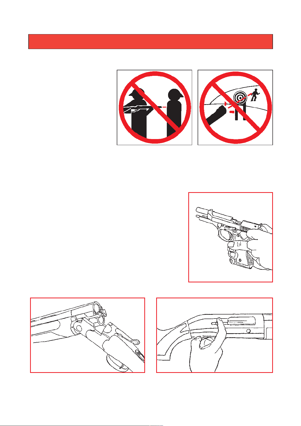
1.
NEVER POINT A FIREARM AT SOMETHING THAT IS NOT SAFE TO SHOOT.
1.
Never let the muzzle of a
firearm point at any part of
your body or at another
person. This is especially
important when loading or
unloading the firearm.
When you are shooting at
a target, know what is
behind it. Some bullets
can travel over a mile. If
you miss your target or if
the bullet penetrates the
target, it is your responsibility to ensure that the shot does not cause unintended
injury or damage.
2. ALWAYS TREAT A FIREARM AS IF IT WERE
LOADED.
2. Never assume that a firearm is unloaded. The
only certain way to ensure that a firearm has
the chamber empty is to open the chamber
and visually examine the inside to see if a
round is present. Removing the magazine will
not guarantee that a firearm is unloaded or
cannot fire. Shotguns and rifles can be checked
by cycling or removing all rounds and by then
opening and inspecting the chamber and the magazine tube for any remaining rounds.
4
Page 5
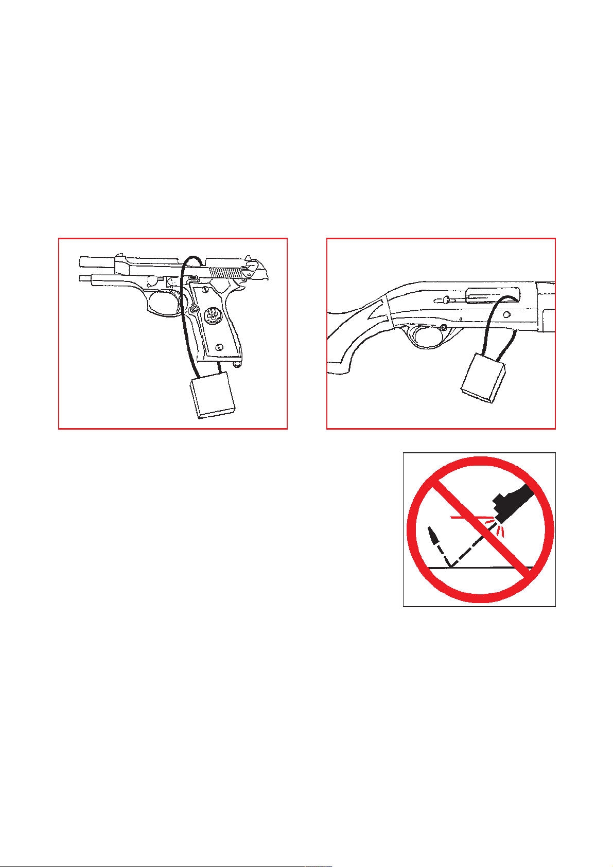
3. STORE YOUR FIREARM SO THAT CHILDREN CANNOT GAIN ACCESS
TO IT.
3. It is your responsibility to insure that children under the age of 18 or other
unauthorized persons do not gain access to your firearm. To reduce the risk of
accidents involving children, unload your firearm, lock it and store the ammunition in a separate locked location. Please note that devices intended to
prevent accidents - for example, cable locks, chamber plugs, etc, - may not prevent use or misuse of your firearm by a determined person. Steel gun safes may
be more appropriate to reduce the likelihood of intentional misuse of a firearm by
an unauthorized child or person.
4. NEVER SHOOT AT WATER OR AT A HARD
SURFACE.
4. Shooting at the surface of water or at a rock or
other hard surface increases the chance of ricochets or fragmentation of the bullet or shot, which
can result in the projectile striking an unintended or
peripheral target.
5. KNOW THE SAFETY FEATURES OF THE FIREARM YOU ARE USING,
BUT REMEMBER: SAFETY DEVICES ARE NOT A SUBSTITUTE FOR SAFE
HANDLING PROCEDURES.
5. Never rely solely on a safety device to prevent an accident. It is imperative that
you know and use the safety features of the particular firearm you are handling,
but accidents can best be prevented by following the safe handling procedures
described in these safety rules and elsewhere in the product manual. To further
familiarize yourself with the proper use of this or other firearms, take a Firearms
Safety Course taught by an expert in firearms use and safety procedures.
5
Page 6
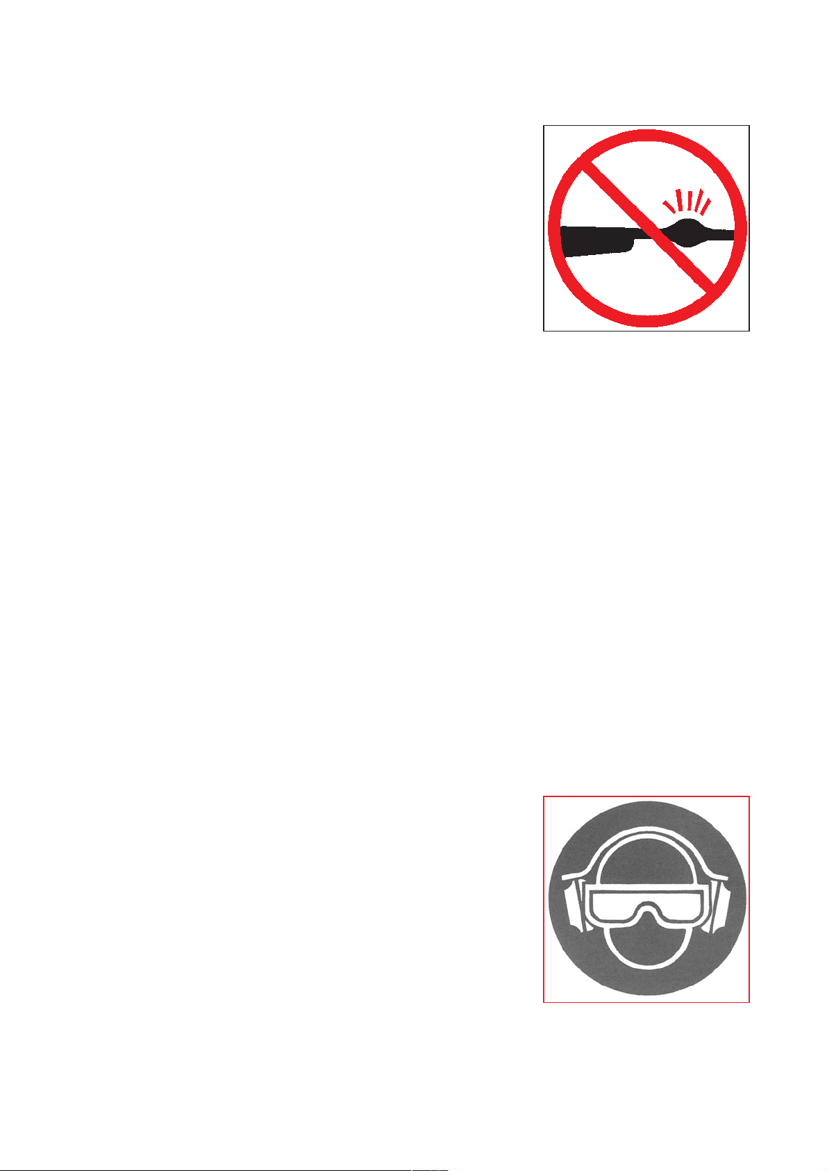
6. PROPERLY MAINTAIN YOUR FIREARM.
1.
Store and carry your firearm so that dirt or lint does
not accumulate in the working parts. Clean and oil
your firearm, following the instructions provided in this
manual, after each use to prevent corrosion, damage
to the barrel or accumulation of impurities which can
prevent use of the gun in an emergency. Always
check the barrel prior to loading to ensure that it is
clean and free from obstructions. Firing against an
obstruction can rupture the barrel and injure
yourself or others nearby.
1.
In case you hear an unusual noise when shooting,
stop firing immediately, engage the manual safety
and unload the firearm. Make sure the chamber and the barrel are free from any
obstruction or possible bullet blocked inside the barrel due to defective or improper ammunition.
7. USE PROPER AMMUNITION.
1.
Only use factory-loaded, new ammunition manufactured to industry specifications: CIP (Europe and elsewhere), SAAMI (U.S.A.). Be certain that each round
you use is in the proper caliber or gauge and type for the particular firearm. The
caliber or gauge of the firearm is clearly marked on the barrels of shotguns and
on the slide or barrel of pistols. The use of reloaded or remanufactured ammunition can increase the likelihood of excessive cartridge pressures, casehead ruptures or other defects in the ammunition which can cause damage to your firearm
and injury to yourself or others nearby.
8.
ALWAYS WEAR PROTECTIVE GLASSES AND EARPLUGS WHEN
SHOOTING.
8.
The chance that gas, gunpowder or metal fragments
will blow back and injure a shooter who is firing a gun
is rare, but the injury that can be sustained in such circumstances is severe, including the possible loss of
eyesight. A shooter must always wear impact resistant shooting glasses when firing any firearm.
Earplugs help reduce the chance of hearing damage
from shooting.
6
Page 7
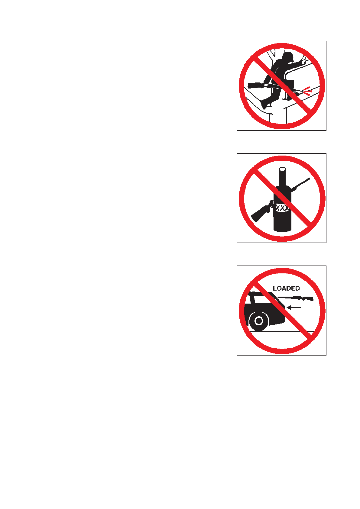
9. NEVER CLIMB A TREE, FENCE OR
OBSTRUCTION WITH A LOADED FIREARM.
9. Open and empty the chamber of your firearm and
engage the manual safety before climbing or descending a tree or before climbing a fence or jumping over a ditch or obstruction. Never pull or push
a loaded firearm toward yourself or another person.
10. AVOID ALCOHOLIC BEVERAGES OR
JUDGMENT OR REFLEX IMPAIRING
MEDICATION WHEN SHOOTING.
10. Do not drink and shoot. If you take medication that
can impair motor reactions or judgment, do not
handle a firearm while you are under the influence
of the medication.
11. NEVER TRANSPORT A LOADED FIREARM.
11. Unload a firearm before putting it in a vehicle
(chamber empty, magazine empty). Hunters and
target shooters should load their firearm only at
their destination. If you carry a firearm for self-protection, leaving the chamber unloaded can reduce
the chance of accidental discharge.
12. LEAD WARNING.
12. Discharging firearms in poorly ventilated areas, cleaning firearms or handling
ammunition may result in exposure to lead and other substances known to cause birth defects, reproductive harm, and other serious physical injury. Have adequate ventilation at all times. Wash hands thoroughly after exposure.
7
Page 8
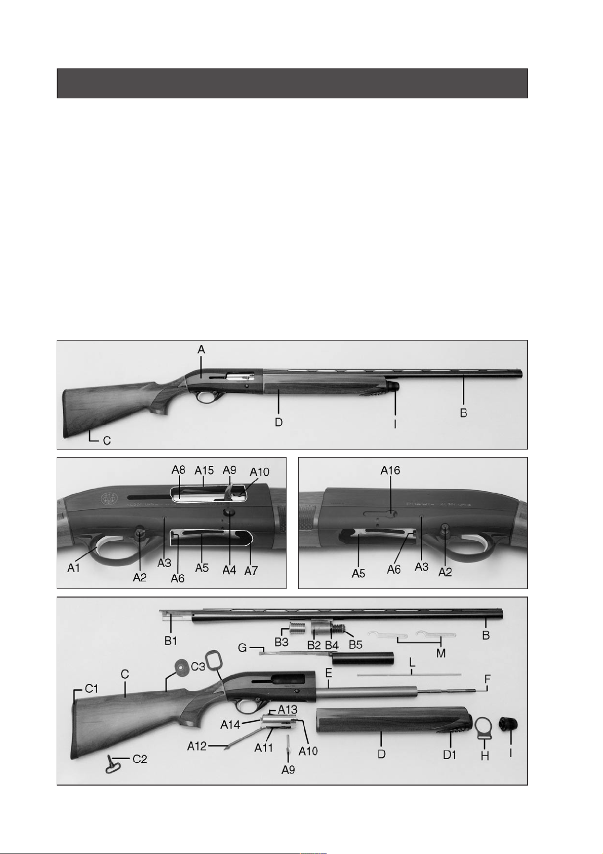
NOMENCLATURE
A Receiver
A1 Trigger
A2 Reversible safety button
A3 Trigger plate retaining pin
A4 Breech bolt release-button
A5 Carrier
A6 Carrier stop push-button
A7 Loading gate
A8 Breech bolt
A9 Cocking handle
A10 Extractor
A11 Breech bolt slide
A12 Connecting rod
A13 Locking block
A14 Firing pin
A15 Ejection port
A16 Cut-off
B Barrel
B1 Barrel tang
B2 Gas cylinder
B3 Piston
B4 Exhaust valve assembly
B5 Valve assembly locking nut and
counter-nut
C Stock
C1 Interchangeable butt plate
C2 Stock swivel
C3 Drop/cast spacers
D Fore-end
D1 Fore-end flange with exhaust port
E Magazine tube
F Magazine tube cap with shaft
G Operating rod with sleeve
H Front swivel
I Fore-end cap
L 1-round magazine capacity
reducer plug
M Valve hook wrenches
8
Page 9
1 2
3 4
5 6
7 8
9 10
9
Page 10

DESCRIPTION
The AL391 Urika/Teknys semi-automatic shotgun, 12 and 20 gauge, comes with the
following features:
STREAMLINED RECEIVER DESIGN
The skilfully rounded shape of the receiver promotes instinctive and quick target
acquisition. The matted anti-glare black-finish of the upper and lower parts of the
receiver highlight the bright finish of the sides to confer to the Beretta AL391
Urika/Teknys a new appearance and distinctive character.
GAS OPERATION SYSTEM WITH EXHAUST VALVE
The unique gas operation system, with gas cylinder and self cleaning piston, is
provided with a self-cleaning exhaust valve which automatically expels the excess
gas of the most powerful cartridges: The result is that the shotgun, without any
adjustment , fires everything from the light 24 gr. (7/8 oz.) loads to the powerful 57
gr. (2 oz.) 3” Magnum 12 ga. shotshells.
The exhaust valve assembly remains attached to the gas cylinder, thus allowing easy
and quick disassembly and reassembly of the shotgun.
RECOIL DAMPER
The elastic recoil damper reduces stress from the impact of the breech bolt on the
receiver and absorbs part of the vibrations normally transmitted to the shooter.
TRIGGER PLATE
The high strength fiber-glass reinforced technopolymer trigger plate offers many
advantages: Self-cleaning property, high absorption of vibrations and more comfort
to the touch in cold weather conditions. The large opening of the trigger guard allows
the use of gloves.
CUT-OFF DEVICE
The cut-off control is positioned on the left side of the receiver: It can be engaged
when the breech bolt is positioned in the closed position with the use of one hand. If
the cut-off is accidentally left engaged, automatic reloading after the first shot will
disengage it.
REVERSIBLE SAFETY BUTTON
The cross-bolt safety button can be assembled for standard right-hand use or
reversed for left-hand use.
10
Page 11

STOCK
The stock is designed to accept either a plastic butt-plate or a rubber recoil pad without any adjustment. By assembling rubber recoil pads of different thickness, one can
modify the length of pull.
X-TRA WOOD STOCK
The AL391 Teknys boasts a semi-gloss X-Tra Wood finish on stock and fore-end.
This unique finish, featuring strong grain lines, enhances the elegant wood of the
stock and the fore-end.
The X-Tra Wood finish is 50% more weatherproof than traditional varnishing.
GEL•TEK RECOIL PAD
The AL391 Teknys is supplied with the Beretta Gel•Tek recoil pad. Its advanced
technology construction consists of a soft yet scratch resistant and durable polymer
shell and a recoil-absorbing silicone gel core. This non-toxic and inert gel distributes
the recoil effect over the entire pad surface, reducing the felt recoil to the shooter.
The gel is unaltered by time and temperature.
STOCK DROP AND CAST SPACERS
The design of the fiber-glass reinforced technopolymer receiver - stock spacer and
of the stock metal plate allows one to adjust the stock drop and cast by simply modifying their assembly position. Different stock drop and cast dimensions can be
obtained using the extra set of spacers supplied.
ACCESSORIES
The AL391 Urika/Teknys is supplied with a modern design case and a complement
of accessories: 1-round magazine capacity reducer plug, spare recoil pad, stock
drop and cast spacers, grip cap (wood stock field models only), fiber optic luminous
insert for Truglo®front sight (AL391 Teknys), stock swivels (field models only), 25 ml.
®
Beretta Gun Oil, valve hook wrenches and, for Mobilchoke
versions, a set of 5
choke tubes with special spanner.
NOTICE: The AL391 Urika/Teknys barrels are not interchangeable with those
of former models (AL 390, A 390 ST, A 304 etc.)
11
Page 12

TECHNICAL FEATURES AND DATA
Gauge
Barrel chamber
Operation
Locking system
Receiver
Barrel
Rib
Front sight
Safety
Magazine
Stock, fore-end
Length of pull
Weight (approx.) *
12, 20
3
/4” and 3”
2
semi-automatic, gas operation with exhaust
valve mounted on the barrel
elevated locking block
light alloy with recoil damper
steel, chrome-plated bore and chamber
ventilated
®
metal bead; Truglo
special front sight for competition models
cross bolt, reversible for left-handed shooters
3 rounds (plugged to 2)
selected walnut, checkered, X-Tra Wood or
high strength fiber-glass reinforced
technopolymer.
Adjustable drop. Cast-off or cast-on
362÷376 mm (14.25”-14.80”) (field)
365÷380 mm (14.37”-14.96”) (competition)
From 3.000 Kg. (6.6 lbs.) to 3.300 Kg. (7.3 lbs.)
(12 ga. field versions)
From 2.700 Kg. (6.0 lbs.) to 3.000 Kg. (6.6 lbs.)
(20 ga.)
From 3.300 Kg. (7.3 lbs.) to 3.500 Kg. (7.7 lbs.)
(12 ga. competition versions)
luminous front sight;
(*)
Weights are approximate, dependent on wood density and barrel length.
NOTICE: The numbers noted below refer to the photographs on pages 9,
32, 33, 34, 35.
OPERATION
ASSEMBLING THE BARREL
The Beretta AL391 Urika/Teknys semi-automatic shotgun is packed from the factory
with the barrel separate from the stock / receiver / fore-end assembly.
WARNING: Beretta assumes no responsibility for any injury or property
damage resulting from improper or careless handling, intentional or accidental
discharge of the firearm.
WARNING: All assembly, disassembly and maintenance procedures should
be carried out with the firearm unloaded (magazine tube empty, receiver empty
and cartridge chamber empty). Check that the firearm is unloaded by looking
through the ejection port, the loading gate and the chamber.
12
Page 13

WARNING: During the assembly, disassembly and maintenance procedures,
never point a firearm at someone or at hard and flat surfaces. Treat the firearm
as if it were loaded. (See points 1, 2 and 4 of the BASIC SAFETY RULES).
Assemble the barrel to the stock / receiver / fore-end assembly as follows:
CAUTION: If, for any reason, the breech bolt is open and the fore-end is
separated from stock / receiver assembly, avoid pressing the breech bolt release button and be careful to keep your fingers away from the ejection port.
Should the breech bolt release button be pressed in this condition, the breech
bolt would slam forward and would stop only when the cocking handle hits the
forward rim of the ejection port. This could damage both the handle and receiver.
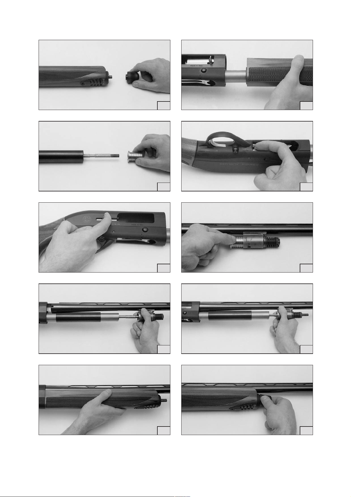
●
Check the barrel. The bore and chamber must be clean and free from obstructions.
●
Unscrew (counterclockwise) the fore-end cap from the stock / receiver / fore-end
assembly. (Fig. 1)
●
Pull the fore-end off the magazine tube. (Fig. 2)
●
Remove the piston. (Fig. 3)
●
Check that the carrier stop push button is completely depressed. If not, depress it
completely. (Fig. 4)
●
Pull the cocking handle backward to bring the breech bolt in the OPEN position.
(Fig. 5)
CAUTION: Should the breech bolt release button be pressed in this condition,
the breech bolt would slam forward and would stop only when the cocking
handle hits the forward rim of the ejection port. This could damage both the
handle and receiver.
●
Insert the piston into the gas cylinder. (Fig. 6)
●
Partially slide the barrel tang into the receiver, taking care that the piston does not
drop out of the gas cylinder and that the magazine tube cap shaft enters the piston
hole as well as that of the gas cylinder and the valve assembly. (Fig. 7)
●
Slide the barrel tang home into the receiver. (Fig. 8)
●
Slide the fore-end into place over the gas cylinder, valve assembly and magazine
tube. Check that the fore-end is perfectly centered on the receiver face. The foreend is correctly assembled when there is no space left between the parts. (Fig. 9)
●
Place the front swivel ring (if desired and supplied) on the fore-end flange and
completely tighten the fore-end cap. (Fig. 10)
●
Close the breech bolt by depressing the breech bolt release button, keeping your
fingers away from the ejection port. (Fig. 11)
CAUTION: While depressing the breech bolt release button to close the
breech bolt, make sure that the cut-off is not inadvertently engaged. Should
this occur, the breech bolt would be kept OPEN by the cut-off lever. In this
case, always keeping your fingers away from the ejection port, close the
breech bolt by operating the cut-off. (Fig. 12)
●
Keeping the breech bolt retracted approximately 2 cm (1 inch), depress the trigger
to lower the hammer. (Fig. 13)
13
Page 14

WARNING: Do not store firearms in places which are or could be accessible
by children or other persons whose unfamiliarity with firearms might lead to
unsafe use. Always store your firearms securely and unloaded, separate from
ammunition. (See point 3 of the BASIC SAFETY RULES).
AMMUNITION
WARNING: Beretta assumes no responsibility for physical injury or property
damage resulting from the use of defective, improper, hand-loaded, reloaded
or remanufactured ammunition. Serious damage and injury, and even death,
could result from the use of incorrect ammunition, from firing against bore
obstructions and from propellant overloads.
The Beretta AL391 Urika/Teknys semi-automatic shotgun features a 3” (76 mm)
chamber. You will find the markings for the gauge and chamber length for your shotgun on the side of the barrel. Every gun has been tested with special proof test ammunition.
WARNING: Never use cartridges that do not correspond to the markings on
the side of the barrel.
WARNING: Use cartridges whose length corresponds or it is inferior to the
chamber length indicated on the side of the barrel.
WARNING: To avoid use of improper ammunition, check markings on the
cartridge box and on the cartridge itself to ensure that the correct gauge and
length of shell is used for your firearm.
STEEL SHOT
The use of steel shot cartridges is not recommended in AL391 Urika/Teknys shotguns with fixed chokes. Beretta “SP” (Steel Proof) Mobilchoke®tubes are designed
for use with factory steel shot cartridges loaded to standard specifications. The best
results with Beretta “SP” choke tubes are obtained using open chokes (CL, IC, M).
Use of tighter constrictions (IM, F) with steel shot does not increase pattern density
and will distort normal pattern density associated with lead shot (i.e. “blown pattern”).
Fixed Chokes & Beretta’s Mobilchoke®Designations
Standard Markings American Choke Tube Compatibility Rim Extra Long
Designation with Steel Shot Notches Tube
0
(*) F (full) SP (1) I •
00(**) IM (Improved Modified) SP (1) II •
000(***) M (Modified) SP III •
0000(****) IC (Improved Cylinder) SP IIII •
C0000(C****) CL (Cylinder) SP IIIII •
SK(Skeet Beretta)(2) SK (Skeet) SP No Notches •
(1) Not recommended. (2) Special Beretta skeet choke with negative value.
Mobilchoke
®
is a registered trademark of Fabbrica d’Armi Pietro Beretta S.p.A.
14
Page 15

LOADING THE FIREARM
WARNING: Before loading the firearm, practice the following loading
procedures without the use of ammunition. Never handle a loaded firearm until
you are fully familiar with the loading procedures. Before loading the shotgun,
make sure that the safety is engaged. Always point the firearm in a safe direc-
tion. (See points 1, 2 and 4 of the BASIC SAFETY RULES).
Always check the barrel prior to loading to ensure that it is clean and free from
obstructions.
WARNING: The shooter and bystanders must always wear eye and hearing
protection. Particles of shot, lead, powder, lubricant, etc. may cause injury to
persons. Hearing protection reduces the risk of hearing damage caused by
exposure to shooting noise.
WARNING: Always keep your fingers away from the trigger and keep the
trigger free from any contact when you do not intend to fire.
●
Check that the carrier stop push button is completely depressed. If not, depress it
completely.
●
Retract the breech bolt by means of the cocking handle until it hooks into the
OPEN position. (Fig. 14)
●
Engage the safety by pushing the safety button until the red ring disappears.
(Fig. 15)
WARNING: When the safety button shows the red ring, the firearm is in the
FIRE position.
WARNING: The manual safety is merely a mechanical device and is in no
way a substitute for the Basic Safety Rules of firearm handling.
NOTICE: The safety can be engaged only when the hammer is cocked.
●
Insert the first round into the cartridge chamber through the ejection port. (Fig. 16)
●
Depress the breech bolt release button to lock the breech bolt, keeping fingers
away from the ejection port. (Fig. 17)
WARNING: The firearm is now loaded and, once the safety is disengaged,
ready to fire. Always keep your fingers away from the trigger and keep the trig-
ger free from any contact when you do not intend to fire. Never point the
firearm at something that is not safe to shoot. (See points 1, 2 and 4 of the
BASIC SAFETY RULES).
NOTICE: The manufacturer assumes no responsibility for any injury or
property damage resulting from improper or careless handling, intentional or
accidental discharge of the firearm.
15
Page 16

CAUTION: Should the breech bolt remain open, check that the cut-off is not
inadvertently engaged. If it is, always keeping your fingers away from the
ejection port, close the breech bolt by operating the cut-off button. (Fig. 12)
●
Insert through the loading gate the other rounds by placing each round on the
carrier and pressing it down and forward into the magazine tube until it engages
the stop tooth. (Fig. 18)
●
To fire, disengage the safety and pull the trigger.
WARNING: If the gun does not fire on a live cartridge when the trigger is
pulled, activate the safety, wait one minute, then unload the firearm as
described in the chapter “Unloading the firearm”.
●
When the last round has been fired, the breech bolt remains open, thus signalling
that the magazine is empty. (Fig. 19)
●
Engage the safety and, if required, reload the firearm as indicated.
USE OF THE CUT-OFF DEVICE
The cut-off device allows one to extract a live round from the cartridge chamber and
lock the breech bolt open for safety or to replace the round in the chamber, without
feeding a new round from the magazine.
WARNING: The firearm is now loaded with a cartridge in the chamber and the
safety is engaged. Never point a firearm at something that is not safe to shoot.
(See points 1, 2 and 4 of the BASIC SAFETY RULES).
●
Make sure that the safety is engaged.
●
Engage the cut-off by depressing the cut-off lever (round side). (Fig. 20)
●
Retract the breech bolt by means of the cocking handle to extract the live round
from the cartridge chamber and eject it through the ejection port. At the end of its
travel, the breech bolt is hooked into the OPEN position by the carrier which is
locked by the cut-off device. Feeding from magazine is blocked. (Fig. 21)
●
Under safety conditions, insert the extracted cartridge or another cartridge into the
cartridge chamber.
●
Keeping fingers away from the ejection port, depress the cut-off lever to close the
breech bolt. (Fig. 12)
WARNING: The firearm is loaded and, once the safety is disengaged, ready
to fire again. Make sure that the safety is fully engaged. Never point a firearm
at something that is not safe to shoot. (See points 1, 2 and 4 of the BASIC
SAFETY RULES).
●
To fire, disengage the safety and pull the trigger.
NOTICE: If the firearm is to function properly, it is recommended that the
cut-off be used as described above. In particular, it must be remembered that
the breech bolt, when held OPEN by the cut-off, can be closed only by
operating the cut-off lever.
16
Page 17

UNLOADING THE FIREARM
WARNING: The firearm is loaded and ready to fire. Always keep your fingers
away from the trigger and keep the trigger free from any contact when you do
not intend to fire. Never point a firearm at someone or at hard and flat
surfaces. (See points 1, 2 and 4 of the BASIC SAFETY RULES).
●
Pointing the firearm in a safe direction, check that safety is engaged (red ring
covered).
●
Engage the cut-off (Fig. 20) and retract the breech bolt to extract and eject the
chambered live round. (Fig. 21)
●
Keeping fingers away from the ejection port, depress the cut-off lever to close the
breech bolt. (Fig. 12)
●
Pressing down the carrier and at the same time pushing against the cartridge in the
magazine, depress the breech bolt release button to ease exit of the shells from
the magazine tube. (Fig. 22)
●
Check to ensure the magazine tube and receiver are empty. Disengage the safety.
Be careful where you point the firearm, even though it might not be loaded.
●
Keeping the breech bolt retracted approximately 2 cm (1 inch), to allow a visual
check of the cartridge chamber to ensure it is empty, depress the trigger to lower
the hammer. (Fig. 13)
DISASSEMBLY
WARNING: Check the firearm is unloaded (cartridge chamber empty, receiver
empty, magazine tube empty). Check that the firearm is unloaded by looking
through the ejection port, the loading gate and the chamber. If the shotgun is
not unloaded, unload it as described in the chapter “Unloading the firearm”.
Lower the hammer on the unloaded gun by pulling the trigger.
WARNING: Never point a firearm at someone or at hard and flat surfaces.
Treat the firearm as if it were loaded. (See points 1, 2 and 4 of the BASIC
SAFETY RULES).
BARREL
●
Check that the carrier stop push button is completely depressed. If not, depress it
completely.
●
Retract the breech bolt until it hooks into the OPEN position. (Fig. 14)
●
Unscrew (counterclockwise) the fore-end cap from the firearm and remove the
front swivel, if mounted. (Fig. 10)
●
With one hand hold down the barrel and with the other hand slide the fore-end off
the magazine tube. (Fig. 9)
●
Grasping the barrel and holding the piston inside the gas cylinder with the right
thumb to prevent dropping it, slide the barrel assembly forward off the stock /
receiver assembly. (Fig. 7)
●
Slide the piston off the gas cylinder. (Fig. 6)
17
Page 18

BREECH BOLT
●
Holding the cocking handle with the index or middle finger of the left hand, depress
the breech bolt release button and allow the breech bolt to slide slowly forward until
it stops. (Fig. 23)
●
Extract the cocking handle from the breech bolt slide. (Fig. 24)
●
Holding the stock / receiver assembly on a table with the ejection port facing
upward, slide the operating rod sleeve forward off the magazine tube to extract the
breech bolt assembly from the receiver. (Fig. 25)
●
The breech bolt assembly, no longer held by the operating rod, will divide into:
(Fig. 26)
●
- breech bolt with firing pin, locking block, extractor, springs and pins;
●
- breech bolt slide with connecting rod and pin.
TRIGGER PLATE
●
Engage the safety (the hammer is cocked).
●
Depress the carrier stop push-button. (Fig. 4)
●
Push out the trigger plate retaining pin by pressing it with a drift punch or other
similar object. (Fig. 27)
●
Keeping the breech bolt release button pressed, extract the trigger plate by pulling
on the trigger guard with a forward and downward movement. (Fig. 28)
CAUTION: Further disassembly of the firearm is not recommended, unless
carried out by a competent gunsmith.
NOTICE: Wholesalers, dealers or gunsmiths (unless they are a Repair Station
authorized by the Manufacturer and/or by its Local Official Distributors) are not
authorized to make any Warranty repair or adjustment on behalf of the
Manufacturer.
BERETTA MOBILCHOKE®TUBES
Mobilchoke®screw-in choke tubes are made of high-grade steel for corrosion
resistance and durability. They are designed to withstand the rigors of non-toxic steel
shot. Mobilchoke®tubes are fully interchangeable among all Beretta Semi-automatic,
Over and Under and Side-by-Side Mobilchoke
Extra long Mobilchoke®tubes are also available and are designed to fit both
single-barrel and double-barrel shotguns. The knurled extension on the tube allows
for easy removal and replacement by hand, without tools.
®
shotguns.
Mobilchoke
®
is a registered trademark of Fabbrica d’Armi Pietro Beretta S.p.A.
18
Page 19

REMOVAL OF CHOKE TUBE
WARNING: Check the firearm is unloaded (cartridge chamber empty, receiver
empty, magazine tube empty). Check that the firearm is unloaded by looking
through the ejection port, the loading gate and the chamber. If not, unload the
firearm by operating as described in the chapter “Unloading the shotgun”.
Lower the hammer on the unloaded gun by pulling the trigger.
WARNING: Never look into the muzzle or change tube on a loaded gun, even
with safety engaged.
●
Unscrew (counterclockwise) the choke using the supplied spanner (Fig. 39).
●
Manually unscrew the extra-long choke.
●
Remove the choke from the muzzle (Fig. 40).
CLEANING OF CHOKE TUBE
WARNING: Check the firearm is unloaded (cartridge chamber empty, receiver
empty, magazine tube empty). Check that the firearm is unloaded by looking
through the ejection port, the loading gate and the chamber. If not, unload the
firearm by operating as described in the chapter “Unloading the shotgun”.
Lower the hammer on the unloaded gun by pulling the trigger.
WARNING: Never look into the muzzle or change tube on a loaded gun, even
with safety engaged.
●
Carefully clean the choke housing. If necessary, use a cotton patch coated with
Beretta Gun Oil. Dry the choke housing using a soft patch.
●
Check the choke to make sure it is perfectly clean inside and outside.
●
Apply a thin coat of Beretta Gun Oil to the thread of the barrel and of the choke
tube.
INSTALLATION OF CHOKE TUBE
WARNING: Check the firearm is unloaded (cartridge chamber empty, receiver
empty, magazine tube empty). Check that the firearm is unloaded by looking
through the ejection port, the loading gate and the chamber. If not, unload the
firearm by operating as described in the chapter “Unloading the shotgun”.
Lower the hammer on the unloaded gun by pulling the trigger.
WARNING: Never look into the muzzle or change tube on a loaded gun, even
with safety engaged.
WARNING: Check the choke to make sure it is not damaged.
●
Check the choke to make sure it is perfectly clean inside and outside.
●
Apply a thin coat of Beretta Gun Oil to the thread of the barrel and of the choke
tube.
●
Insert the desired choke into the choke housing.
19
Page 20

●
Carefully hand screw the choke into the barrel clockwise. Using the Beretta
spanner tighten the choke until it is fully bottomed into its recess in the barrel.
NOTICE: To tighten the extra long tube, it is sufficient to hand-tighten it until
seated firmly.
●
Remove the spanner after tightening.
WARNING: Periodically check, under safe conditions (firearm unloaded with
cartridge chamber empty, receiver empty, magazine tube empty and breech
bolt in OPEN position) whether the choke is fully and tightly set into the barrel.
If necessary, firmly tighten the choke, using the Beretta spanner, until it can be
tighten no more.This tightening is needed to avoid damage to the barrel and to
avoid propelling the choke out of the muzzle when the gun is fired, which may
cause damage to the gun or injury to persons.
WARNING: Choke tube must be kept correctly tightened in the barrel at all
times, even during storage and cleaning. Cleaning barrel with no choke tube
in place can push dirt into the barrel thread, causing improper choke
installation, rusting, or barrel obstruction.
WARNING: Never shoot choke barrel without using choke tube. Shooting
without choke tube is very dangerous as debris could be trapped by the thread
and create barrel obstructions. It may also cause erratic shot pattern and can
damage the barrel’s internal screw thread irreparably.
Do not alter or modify existing fixed choke Beretta barrel for the use of
interchangeable choke tubes. The resulting wall thickness would be too thin
to safely contain the pressure levels generated by shooting.
ROUTINE MAINTENANCE
When combustion residues, grease or dirt particles have accumulated in the action,
clean and lubricate the firearm.
Cleaning and lubrication of the shotgun after use is the best guarantee for protection
of parts against corrosion deriving from combustion residues and from use of the
firearm in humid or saline environments.
At the end of the hunting or shooting day, perform the Routine Maintenance as
indicated.
WARNING: Check that the firearm is unloaded (cartridge chamber empty,
receiver empty, magazine tube empty). Check that the firearm is unloaded by
looking through the ejection port, the loading gate and the chamber. If the
shotgun is not unloaded, unload it as described in the chapter “Unloading the
firearm”. Lower the hammer on the unloaded gun by pulling the trigger.
WARNING: Never point a firearm at someone or at hard and flat surfaces.
Treat the firearm as if it were loaded. (See points 1, 2 and 4 of the BASIC
SAFETY RULES).
20
Page 21

WARNING: Excess oil and grease obstructing the bore even partially are very
dangerous when firing and may cause damages to the shotgun and serious
injury to the shooter and bystanders. Never spray or apply oil to the shotshells.
Use lubricants properly: you are responsible for the proper care and
maintenance of your firearm.
BARREL
●
After use, thoroughly clean the barrel bore by passing a swab through it to remove
combustion residues. If necessary, use a cleaning rod with bronze brush and/or a
patch soaked in a bore cleaning solvent.
●
Thoroughly clean the barrel tang locking shoulder.
●
Pull a clean soft patch through the barrel bore.
●
Lightly lubricate the barrel bore by pulling through it a soft clean patch treated with
Beretta gun oil.
●
Check the barrel and the cartridge chamber to ensure that they are clean and free
from obstructions.
CAUTION: Do not apply excess oil: accumulation of oil attracts dirt which can
plug the barrel and interfere with the functioning and reliability of the gun.
GAS CYLINDER, PISTON, MAGAZINE TUBE CAP SHAFT, EXHAUST VALVE
ASSEMBLY
CAUTION: Magnum cartridges and particularly Super Magnum (3”) shotshells
produce a high amount of combustion gases. The particular composition of
some Super Magnum shotshells’ powder can generate a strong deposit of
combustion residues. The parts of the shotgun which, coming into contact with
the gases, are more affected by the combustion residues are the gas cylinder
(inside) and the piston with its bushing.
●
Check that the piston slides freely inside the gas cylinder.
●
Carefully clean the inner side of the gas cylinder with a bronze brush sprayed with
Beretta gun oil.
●
When all combustion residues are removed, clean the inside of the gas cylinder
with a soft cloth.
●
Carefully clean the piston and check that the piston bushing can move freely in its
housing.
●
If necessary, also clean the exhaust valve and the magazine tube cap shaft.
CAUTION: Do not oil these parts.
Every 500-1000 rounds (according to the type of ammunition used) and in any
case at the end of the hunting or shooting season, before storing the shotgun,
complete the Routine Maintenance with the following extra operations.
21
Page 22

FORE-END FLANGE
●
Carefully clean the fore-end flange exhaust valve port with a soft brush sprayed
with Beretta gun oil. Carefully dry the flange with a soft cloth.
BREECH BOLT ASSEMBLY
●
Thoroughly clean the parts with a small brush and Beretta gun oil.
●
Carefully dry with a soft cloth and lightly oil the parts with Beretta gun oil.
TRIGGER PLATE
●
Thoroughly clean the parts with a soft cloth.
●
Lightly oil the metal parts and the trigger plate retaining pin.
RECEIVER
●
Maintain as described for the breech bolt assembly. Lightly oil the slide rails of the
breech bolt inside the receiver.
MAGAZINE TUBE
●
Clean the outside of the magazine tube with a soft cloth sprayed with Beretta gun
oil.
●
Carefully dry with a soft cloth and lightly oil the parts.
WARNING: Do not attempt to make repairs to any firearm without proper
knowledge or training. Do not alter parts or use substitute parts not made by
Beretta. Any alterations or adjustments that may be necessary to the
operating mechanism should be performed by the Manufacturer or by its Local
Official Distributor.
Every 3000-5000 rounds (according to the type of ammunition used) and in any
case at the end of the hunting or shooting season, before storing the gun, in
addition to the Routine Maintenance, perform the Special Maintenance as
described later in this manual.
REASSEMBLY
WARNING: Check that the firearm is unloaded (cartridge chamber empty,
receiver empty, magazine tube empty). Check that the firearm is unloaded by
looking through the ejection port, the loading gate and the chamber. If the
shotgun is not unloaded, unload it as described in the chapter “Unloading the
firearm”. Lower the hammer on the unloaded gun by pulling the trigger.
WARNING: Never point a firearm at someone or at hard and flat surfaces.
Treat the firearm as if it were loaded. (See points 1, 2 and 4 of the BASIC
SAFETY RULES).
22
Page 23

TRIGGER PLATE
●
Operate in the reverse order to what is described in the chapter “Disassembly”
making sure that the hammer is cocked, the safety engaged and the carrier stop
push-button depressed. (Fig. 28)
●
Insert the trigger plate retaining pin, ensuring that the trigger plate hole is centered
on the receiver hole.
BREECH BOLT
●
Reassemble the breech bolt slide with connecting rod to the breech bolt. (Fig. 36)
●
Insert the operating rod into the breech bolt slide slot. (Fig. 37)
●
Depress the carrier stop push-button. (Fig. 4)
●
Holding the stock/receiver assembly on a table with the ejection port facing upward,
slide the operating rod sleeve on the magazine tube (the breech bolt rests on the
operating rod) and partially insert the breech bolt inside the receiver. (Fig. 25)
●
Holding the stock/receiver vertically, slide the operating rod sleeve downward,
compressing the recoil spring until the breech bolt hooks into the OPEN position.
(Fig. 38)
NOTICE: To carry out the described operation with ease, the head of the
breech bolt connecting rod must rest in the recoil spring guide housing. This
will easily occur when the connecting rod is perfectly coaxial to the breech bolt
and centered in the cocking handle slideway of the receiver.
●
Insert the cocking handle into the breech bolt slide and push it until it clicks home.
(Fig. 24)
BARREL
●
Check the barrel. The bore and cartridge chamber must be clean and free from
obstructions.
●
Insert the piston into the gas cylinder. (Fig. 6)
●
Check that the breech bolt is in the OPEN position.
CAUTION: Should the breech bolt release button be pressed in this condition,
the breech bolt would slam forward and would stop only when the cocking
handle hits the forward rim of the ejection port. This could damage both the
handle and the receiver.
●
Partially slide the barrel tang into the receiver, taking care that the piston does not
drop out of the gas cylinder and that the magazine tube cap shaft enters the piston
hole as well as that of the gas cylinder and the valve assembly. (Fig. 7)
●
Slide the barrel tang home into the receiver. (Fig. 8)
●
Slide the fore-end into place over the gas cylinder, valve assembly and magazine
tube. Check that the fore-end is perfectly centered on the receiver face. The foreend is correctly assembled when there is no space left between the parts. (Fig. 9)
23
Page 24

●
Place the front swivel ring (if desired and supplied) on the fore-end flange and
completely tighten the fore-end cap. (Fig. 10)
●
Close the breech bolt by depressing the breech bolt release button, keeping your
fingers away from the ejection port. (Fig. 11)
CAUTION: While depressing the breech bolt release button to close the
breech bolt, make sure that the cut-off is not inadvertently engaged. Should
this occur, the breech bolt would be kept OPEN by the cut-off lever. In this
case, always keeping your fingers away from the ejection port, close the
breech bolt by operating the cut-off. (Fig. 12)
●
Keeping the breech bolt retracted approximately 2 cm (1 inch), depress the trigger
to lower the hammer. (Fig. 13)
WARNING: Do not store firearms in places which are or could be accessible
by children or other persons whose unfamiliarity with firearms might lead to
unsafe use. Always store your firearms securely and unloaded, separate from
ammunition. (See point 3 of the BASIC SAFETY RULES).
CAUTION: It is recommended to store the firearm disassembled (barrel
separate from the stock/receiver/fore-end assembly) in the supplied case.
Before storage, always check the conditions of the gun and its case. Make
sure that they are perfectly dry.
Moisture and water drops could cause damage to the shotgun.
SPECIAL MAINTENANCE
Every 3000-5000 rounds (according to the type of ammunition used) and in any
case at the end of the hunting season, before storing the shotgun, in addition
to the Routine Maintenance, also perform the following Special Maintenance
operations.
WARNING: Check the firearm is unloaded (cartridge chamber empty, receiver
empty, magazine tube empty). Check that the firearm is unloaded by looking
through the ejection port, the loading gate and the chamber. If the shotgun is
not unloaded, unload it as described in the chapter “Unloading the firearm”.
Lower the hammer on the unloaded gun by pulling the trigger.
WARNING: Never point a firearm at someone or at hard and flat surfaces.
Treat the firearm as if it were loaded. (See points 1, 2 and 4 of the BASIC
SAFETY RULES).
EXHAUST VALVE ASSEMBLY
CAUTION: Use only the supplied hook wrenches to screw and unscrew the
valve assembly locking nut and counter-nut. These spanners are designed
and have the right dimensions to produce the correct driving torque when a
force of medium intensity is applied. Never attempt to use different wrenches
which could produce an excessive driving torque. Do not apply excessive
force when using the supplied spanners.
24
Page 25

CAUTION: Before starting the disassembly of the exhaust valve assembly,
carefully observe the position of the components parts. This will be of great
help during the reassembly operations.
DISASSEMBLY AND CLEANING
●
Remove the barrel from the shotgun.
●
Unscrew the valve assembly counter-nut using the supplied hook wrench,
operating counterclockwise. (Fig. 29)
●
Unscrew the valve assembly nut using the supplied wrench. (Fig. 30)
●
Slide from the valve shaft the spring, the valve and the valve centering ring.
(Fig. 31)
●
Slide from the gas cylinder the valve shaft. (Fig. 32)
●
Thoroughly clean the parts with Beretta gun oil. If necessary, use a bronze brush.
CAUTION: Be careful not to damage the threaded surfaces with excessive
rubbing.
●
Carefully dry with a soft cloth.
●
Lightly oil the parts with Beretta gun oil.
CAUTION: Do not apply excess oil: accumulation of oil attracts dirt which can
plug the barrel and interfere with the functioning and reliability of the gun.
REASSEMBLY
●
Insert the valve shaft into the gas cylinder, letting the shaft lugs enter the cylinder
recesses. (Fig. 33)
●
Place the valve centering ring, the valve and the valve spring around the valve
shaft .
●
Make sure that the valve is assembled with the outside recess turned to contain the
first coil of the spring. (Fig. 34)
●
Manually screw the valve nut on the valve shaft until tight.
●
Using the supplied hook wrench, tighten the valve nut against the valve centering
ring.
●
Manually screw the valve counter-nut on the valve shaft until tight against the valve
nut.
●
Keeping the valve nut tight using one of the two hook wrenches, tighten the
counter-nut against the nut with the other wrench. (Fig. 35)
25
Page 26

MAGAZINE CAPACITY
The magazine tube capacity of the AL391 Urika/Teknys (which has a three-round capacity) has been limited to two rounds by the application of a plug in order to comply
with the sporting gun laws in force in many countries.
This plug, which is factory mounted, reduces the capacity of the AL391 Urika/Teknys
to no more than three rounds (two in the magazine, one in the chamber).
In some areas, shooting is allowed only with shotguns having a capacity of no more
than two rounds.
To use the AL391 Urika/Teknys in these areas, it will be necessary to limit the magazine capacity to only one round.
It is possible to increase the magazine capacity from two to three rounds in the
countries where it is allowed.
NOTICE: These operations must be carried out by a competent gunsmith.
NOTICE: Wholesalers, dealers or gunsmiths (unless they are a Repair Station
authorized by the Manufacturer and/or by its Local Official Distributors) are not
authorized to make any Warranty repair or adjustment on behalf of the
Manufacturer.
STOCK DROP AND CAST MODIFICATION
The Beretta AL391 Urika/Teknys semi-automatic shotgun is factory set with a heel
drop of 55 or 60 mm (2.16” or 2.36”) (field, sporting, skeet models), of 40 mm. (1.57”)
(trap models) and cast-off (right-handed shooters).
The components which determine the drop and the cast are: (See drawing next page)
➀ Receiver-stock spacer made of technopolymer, fiber-glass reinforced.
➁ Stock metal plate.
Both the spacer ➀ and the plate ➁ are designed to secure two different drops with
cast-off or with cast-on (for left handed shooters) depending on how they are
assembled.
Other measures of stock drop can be obtained using the supplied extra set of
spacers.
CHANGING THE STOCK DROP AND CAST SPACERS
NOTICE: The “DX” mark on the spacer and on the plate means “cast-off”, the
“SX” mark means “cast-on”. The stock drop measures are in millimetres. The
stock drop and cast of the spacer ➀ must always correspond to those of the
metal plate ➁.
NOTICE: Stock drop and cast modification must be carried out by a competent
gunsmith.
NECESSARY TOOLS
●
Screwdriver.
●
Hexagonal tube spanner (13 mm).
●
Torque wrench (suggested).
26
Page 27

WARNING: Check that the firearm is unloaded (cartridge chamber empty,
receiver empty, magazine tube empty). Check that the firearm is unloaded by
looking through the ejection port, the loading gate and the chamber. If the
shotgun is not unloaded, unload it as described in the chapter “Unloading the
firearm”. Lower the hammer on the unloaded gun by pulling the trigger.
WARNING: Never point a firearm at someone or at hard and flat surfaces.
Treat the firearm as if it were loaded. (See points 1, 2 and 4 of the BASIC
SAFETY RULES).
REMOVING THE RECOIL PAD
In case of conventional recoil pad:
With a Phillips-head screwdriver unscrew and remove the retaining screws.
In case of Gel•Tek recoil pad:
●
With a flathead screwdriver (approx. 4 mm/0.2”), pull out retaining clasp of the
Gel•Tek recoil pad. (Fig. 41)
●
Remove the Gel•Tek recoil pad. (Fig. 42)
STOCK DROP AND CAST MODIFICATION
●
Disassemble the stock using the spanner and take off the spacers.
●
Put the spacer ➀ around the
stock bolt tube. Make sure that
the spacer shows on the top the
drop and cast wanted (“C-60-DX”
in the drawing).
●
Put the rear plate ➁ and the washer in
the back hole of the stock until the plate
reaches its own seat in the stock. Make sure
that the plate shows on the top the same drop
and cast of the spacer on the top (“C-60-DX” in
the drawing).
●
Use the screwdriver to center the plate and the
washer.
●
Assemble the stock, making sure to locate the stock bolt
tube through the rear plate ➁ and the washer. Also make
sure that the front spacer ➀ is centered between the stock and
the receiver. (During this operation keep the shotgun vertical with
the barrel down).
●
Using the spanner, screw on and tighten the stock retaining nut with a
torque of about 1,6/1,8 kgm (11.6/13.0 Ftlb) (Kg meter). A torque wrench is useful
for this purpose.
●
Screw on the recoil pad.
WARNING: The improper observance of this procedure could cause damage
to the shotgun and/or injury to the bystanders.
27
Page 28

REASSEMBLING THE GEL•TEK RECOIL PAD
●
With a flathead screwdriver (approx. 4 mm/0.2”), pull out retaining clasp of the
Gel•Tek recoil pad. (Fig. 42)
●
Place the pad on the stock and make sure that all bushings are placed in the
proper holes. (Fig. 41)
●
While securely pushing the pad against the stock, push retaining clasp back, until
it disappears in the pad assembly. Be sure that the pad fits flush to the stock without movement. (Fig. 43)
REPLACEMENT OF RECOIL PAD
The standard plastic butt-plate, rubber recoil pad, or Gel•Tek can be replaced with
other Beretta recoil pads of different thickness and material (optional) without any
adjustment. By assembling recoil pads of different thickness it is possible to modify
the length of pull.
NOTICE: This operation must be carried out by a competent gunsmith.
REPLACING THE GEL•TEK PAD WITH A CONVENTIONAL RECOIL PAD
●
With a flathead screwdriver (approx. 4 mm/0.2”), pull out retaining clasp of the
Gel•Tek recoil pad. (Fig. 41)
●
Remove the Gel•Tek recoil pad. (Fig. 42)
●
Unscrew and remove the retaining screws and their bushings from the buttstock,
using a Phillips-head screwdriver.
●
Pressing the conventional recoil pad firmly against the buttstock, insert the screws
through the recoil pad and into the buttstock’s pre-drilled holes and tighten them
with a Phillips-head screwdriver. It is advisable to oil the screwdriver head in order
to facilitate its entry into the rubber material of the pad.
●
Tighten the screws.
REPLACING THE CONVENTIONAL RECOIL PAD WITH A GEL•TEK PAD
●
Unscrew and remove the retaining screws with a Phillips-head screwdriver and
detach the recoil pad from the buttstock. It is advisable to oil the screwdriver head
in order to facilitate its entry into the rubber material of the pad.
●
With a flathead screwdriver (approx. 4 mm/0.2”), pull out retaining clasp of the
Gel•Tek recoil pad. (Fig. 44)
●
Insert bushings in their lodgings in the stock and securely tighten all screws using
a properly sized Phillips-head screwdriver. (Fig. 42)
●
Place the pad on the stock, and make sure that all bushings are placed in the
proper holes. (Fig. 41)
●
While securely pushing the pad against the stock, push retaining clasp back, until
it disappears in the pad assembly. Be sure that the pad fits flush to the stock without movement. (Fig. 43)
28
Page 29

REVERSIBLE SAFETY BUTTON
WARNING: Check that the firearm is unloaded (cartridge chamber empty,
receiver empty, magazine tube empty). Check that the firearm is unloaded by
looking through the ejection port, the loading gate and the chamber. If the
shotgun is not unloaded, unload it as described in the chapter “Unloading the
firearm”. Lower the hammer on the unloaded gun by pulling the trigger.
WARNING: Never point a firearm at someone or at hard and flat surfaces.
Treat the firearm as if it were loaded. (See points 1, 2 and 4 of the BASIC
SAFETY RULES).
The safety button is factory assembled to be engaged by pushing it from the left to
the right side of the receiver and disengaged in the opposite direction with the index
finger of the right hand (right-handed shooters).
By reversing the safety button, the safety is engaged by pushing from the right to the
left side of the receiver and is disengaged in the opposite way by using the index
finger of the left hand (left-handed shooters).
To invert the safety button:
Cock the hammer. Keeping the safety plunger depressed with a drift punch, push the
safety out of its housing (from the right to the left side of the firearm).
CAUTION: The safety plunger spring, when mounted, is in a compressed
condition. Take care not to lose the plunger and its spring.
Reverse the safety and insert it into its housing from the left to the right side of the
firearm and click it into position, keeping the safety plunger depressed.
NOTICE: This operation must be carried out by a competent gunsmith.
®
REPLACEMENT OF TRUGLO
FRONT SIGHT LUMINOUS INSERT
(AL 391 Teknys)
To replace the fiber optic luminous insert with the one of diverse color supplied, proceed as follows:
• Disengage the luminous insert from the front ring by lightly pressing downwards.
Extract the insert by running it in reverse so that it completely protrudes from the
rear ring.
• Push the luminous insert provided into the rear ring. Press downwards and slide the
front part of the insert towards the front ring until a distinctive click is felt.
• Check that the luminous insert is firmly fixed.
29
Page 30

WARRANTY AND EXTENSION OF THE
WARRANTY REPAIR PERIOD
The Warranty and extension of the Warranty repair period is packed with your new
Beretta firearm. Please refer to the WARRANTY and the instructions given on it in
case Warranty service is required.
NOTICE: Wholesalers, dealers or gunsmiths (unless they are a Repair Station
authorized by the Manufacturer and/or by its Local Official Distributors) are not
authorized to make any Warranty repair or adjustment on behalf of the
Manufacturer.
NOTICE: The Warranty is effective only for the original retail purchaser of the
firearm.
30
Page 31

Page 32

The photographs from n°1 to n°10 are on page 9.
11 12
13 14
15 16
17 18
19 20
32
Page 33

21 22
23 24
25 26
27 28
29 30
33
Page 34

31 32
33 34
35 36
34
37 38
39 40
Page 35

4241
43
Le illustrazioni e descrizioni di questo opuscolo si intendono fornite a titolo indicativo. La Casa si riserva pertanto il
diritto di apportare ai suoi modelli, in qualsiasi momento e senza preavviso, quelle modifiche che ritenesse utili per
migliorarli o per qualsiasi esigenza di carattere costruttivo e commerciale.
44
The illustrations and descriptions given in this brochure are intended as a general guide only, and must not be taken
as binding. The Company, therefore, reserves the right to make, at any moment and without notice, any changes it
thinks necessary to improve its models or to meet any requirements of manufacturing or commercial nature.
Les illustrations et les descriptions contenues dans ce prospectus ne sont données qu'à titre indicatif. La Maison se
réserve le droit de modifier, à tout moment et sans préavis, ses modèles pour les améliorer ou pour n'importe quelle
exigence de caractère constructif et commercial.
Beretta Pubblicità - cod. 61160
06/02
Printed in Italy
Batan - Gardone V.T.
Page 36

Urika
AL391
Teknys
AVVERTENZA
ALLA CONSEGNA IL FUCILE AL391 URIKA/TEKNYS È DOTATO DI UNA BUSSOLA ROSSA
DI SERVIZIO CHE HA LO SCOPO DI CENTRARE IL TAPPO E L’ASTINA QUANDO L’ARMA
È MONTATA SENZA LA CANNA. SI RACCOMANDA:
1 - DI RIMUOVERE LA BUSSOLA ROSSA DI SERVIZIO QUANDO SI MONTA LA CANNA.
2 - DI UTILIZZARE LA BUSSOLA ROSSA DI SERVIZIO QUANDO SI RIMONTA IL FUCILE
SENZA LA CANNA PER METTERLO IN VALIGETTA.
ATTENTION
ON DELIVERY THE AL391 URIKA/TEKNYS SHOTGUN IS PROVIDED WITH A SPARE RED
BUSH WHICH IS USED IN ORDER TO FIT THE CAP WITH THE FORE-END WHEN THE
SHOTGUN IS MOUNTED WITHOUT THE BARREL. DO NOT FORGET TO:
1 - REMOVE THE SPARE RED BUSH WHEN YOU ARE MOUNTING THE BARREL.
2 - USE THE SPARE RED BUSH WHEN YOU REMOUNT THE SHOTGUN WITHOUT
THE BARREL IN ORDER TO PUT IT INTO THE CASE.
PRECAUTION D’USAGE
LE FUSIL SEMI-AUTOMATIQUE AL391 URIKA/TEKNYS EST LIVRÉ AVEC UN MANCHON
ROUGE DE SERVICE QUI PERMET DE CENTRER LE BOUCHON ET LE DEVANT BOIS
QUAND L’ARME EST EN CONFIGURATION DE TRANSPORT DANS SA MALLETTE, C’EST
À DIRE SANS QUE LE CANON SOIT MONTÉ. NOUS RECOMMANDONS DONC DE:
1 - ENLEVER LE MANCHON ROUGE DE SERVICE POUR MONTER LE CANON.
2 - UTILISER LE MANCHON ROUGE DE SERVICE POUR METTRE L’ARME AVEC SON
DEVANT BOIS EN CONFIGURATION DE TRANSPORT DANS SA MALLETTE, C’EST À
DIRE LE CANON DEMONTÉ.
Fabbrica d'Armi Pietro Beretta S.p.A.
Via Pietro Beretta, 18
25063 GARDONE VAL TROMPIA (Brescia) Italia
Tel. (030) 8341.1 - info@beretta.com
www.beretta.com
 Loading...