

Page 1
A391
Xtrema2
Manuale di Istruzione
Instruction Manual
Mode d’Emploi
Page 2

38
NOTICE: The Manufacturer and/or its Local Official Distributors assume no
responsibility for product malfunction or for physical injury or property damage
resulting in whole or in part from criminal or negligent use of the product,
improper or careless handling, unauthorized modifications, use of defective,
improper, hand-loaded, reloaded or remanufactured ammunition, customer
abuse or neglect of the product, or other influences beyond manufacturer's
direct and immediate control.
WARNING: READ THE ENTIRE MANUAL CAREFULLY BEFORE USING
THIS FIREARM. MAKE SURE THAT ANY PERSON USING OR HAVING
ACCESS TO THIS FIREARM READS AND UNDERSTANDS ALL OF THIS
MANUAL PRIOR TO USE OR ACCESS.
WARNING: FIREARMS CAN BE DANGEROUS AND CAN POTENTIALLY
CAUSE SERIOUS INJURY, DAMAGE TO PROPERTY OR DEATH, IF
HANDLED IMPROPERLY. THE FOLLOWING SAFETY RULES ARE AN
IMPORTANT REMINDER THAT FIREARM SAFETY IS YOUR
RESPONSIBILITY.
In addition to the Basic Safety Rules, there are other Safety Rules pertaining to the
loading, unloading, disassembly, assembly and use of this firearm, located
throughout this manual.
NOTICE: The interchangeable barrel of this shotgun has a serial number
different from that stamped on the receiver.
ALWAYS KEEP THIS MANUAL WITH YOUR FIREARM. INCLUDE IT WITH THE
GUN WHEN IT CHANGES OWNERSHIP OR WHEN IT IS LOANED OR
PRESENTED TO ANOTHER PERSON.
ENGLISH
Illustrations on pages 48, 108, 109, 110 and 111
FRANÇAIS
page 72
WE RECOMMEND THE USE OF ORIGINAL BERETTA SPARE PARTS AND
ACCESSORIES. THE USE OF OTHER MANUFACTURER’S SPARE PARTS
AND ACCESSORIES COULD CAUSE MALFUNCTIONS AND/OR
BREAKAGES THAT WILL NOT BE COVERED BY THE BERETTA
WARRANTY.
Page 3

39
CONTENTS
Page
BASIC SAFETY R ULES 40
NOMENCLATURE 44
DESCRIPTION 45
TECHNICAL FEATURES AND DATA 49
ASSEMBLY OF THE PACKED SHOTGUN 50
LOAD CHECK 52
OBSTRUCTION CHECK 53
AMMUNITION 53
LOADING THE FIREARM 55
USE OF THE CUT-OFF DEVICE 57
UNLOADING THE FIREARM 57
DISASSEMBLY 58
BERETTA OPTIMACHOKE
®
PLUS TUBES 60
ROUTINE MAINTENANCE 62
SPECIAL MAINTENANCE 64
REASSEMBLY 65
GEL•TEK RECOIL PAD 67
STOCK SPACERS 68
STOCK DR OP AND CAST MODIFICATION 69
REPLACEMENT OF TRUGLO
®
FRONT SIGHT
LUMINOUS INSERT 71
STORAGE 71
This instruction manual consists of 111 pages.
Page 4
40
BASIC SAFETY RULES
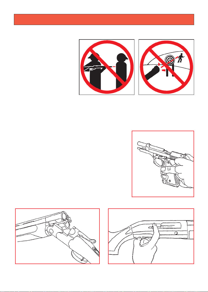
1.NEVER POINT A FIREARM AT SOMETHING THAT IS NOT SAFE TO SHOOT.
Never let the muzzle of a
firearm point at any part of
your body or at another
person. This is especially
important when loading or
unloading the firearm.
When you are shooting at
a target, know what is
behind it. Some bullets can
travel over a mile. If you
miss your target or if the
bullet penetrates the target,
it is your responsibility to
ensure that the shot does not cause unintended injury or damage.
2.ALWAYS TREAT A FIREARM AS IF IT WERE LOADED.
Never assume that a firearm is unloaded. The only
certain way to ensure that a firearm has the
chamber(s) empty is to open the chamber and
visually and physically examine the inside to
see if a round is present.
Removing or unloading the magazine will not
guarantee that a firearm is unloaded or cannot
fire. Shotguns and rifles can be checked by cycling
or removing all rounds and by then opening and
inspecting the chamber so that a visual inspection
of the chamber for any remaining rounds can be
made.
Page 5

41
3.STORE YOUR FIREARM SO THAT CHILDREN CANNOT GAIN ACCESS TO IT.
It is your responsibility to ensure that children under the age of 18 or other
unauthorized persons do not gain access to your firearm. To reduce the risk of
accidents involving children, unload your firearm, lock it and store the
ammunition in a separate locked location. Please note that devices intended to
prevent accidents - for example, cable locks, chamber plugs, etc, - may not
prevent use or misuse of your firearm by a determined person. Firearm storage in
a steel gun safe may be more appropriate to reduce the likelihood of intentional
misuse of a firearm by an unauthorized child or person.
4.NEVER SHOOT AT WATER OR AT A HARD
SURFACE.
Shooting at the surface of water or at a rock or
other hard surface increases the chance of
ricochets or fragmentation of the bullet or shot,
which can result in the projectile striking an
unintended or peripheral target.
5. KNOW THE SAFETY FEATURES OF THE FIREARM YOU ARE USING, BUT
REMEMBER: SAFETY DEVICES ARE NOT A SUBSTITUTE FOR SAFE
HANDLING PROCEDURES.
Never rely solely on a safety device to prevent an accident. It is imperative that you
know and use the safety features of the particular firearm you are handling, but
accidents can best be prevented by following the safe handling procedures
described in these safety rules and elsewhere in the product manual. To further
familiarize yourself with the proper use of this or other firearms, take a Firearms
Safety Course taught by an expert in firearms use and safety procedures.
Page 6
42
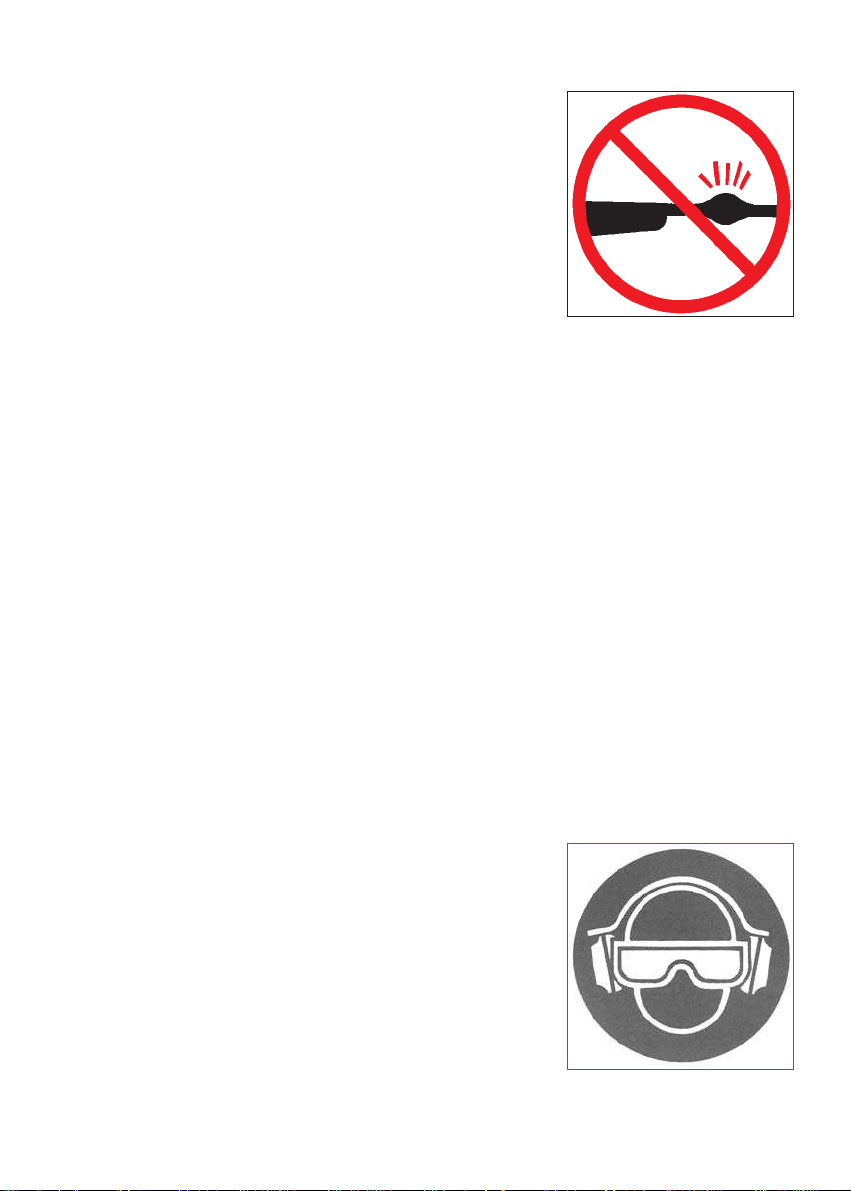
8.ALWAYS WEAR PROTECTIVE GLASSES AND EARPLUGS WHEN
SHOOTING.
The chance that gas, gunpowder or metal fragments
will blow back and injure a shooter who is firing a gun
is rare, but the injury that can be sustained in such
circumstances can be severe, including the possible
loss of eyesight. A shooter must always wear impact
resistant shooting glasses when firing any firearm.
Earplugs or other high-quality hearing protectors help
reduce the chance of hearing damage from shooting.
6.PROPERLY MAINTAIN YOUR FIREARM.
Store and carry your firearm so that dirt or lint does not
accumulate in the working parts. Clean and oil your
firearm, following the instructions provided in this
manual, after each use to prevent corrosion, damage
to the barrel or accumulation of impurities which can
prevent use of the gun in an emergency. Always check
the bore and chamber(s) prior to loading to ensure that
they are clean and free from obstructions. Firing with
an obstruction in the barrel or chamber can
rupture the barrel and injure you or others nearby.
In the event you hear an unusual noise when shooting,
stop firing immediately, engage the manual safety and
unload the firearm. Make sure the chamber and barrel
are free from any obstruction, like a bullet blocked inside the barrel due to defective
or improper ammunition.
7.USE PROPER AMMUNITION.
Only use factory-loaded, new ammunition manufactured to industry specifications:
CIP (Europe and elsewhere), SAAMI®(U.S.A.). Be certain that each round you
use is in the proper caliber or gauge and type for the particular firearm. The caliber
or gauge of the firearm is clearly marked on the barrels of shotguns and on the
slide or barrel of pistols. The use of reloaded or remanufactured ammunition can
increase the likelihood of excessive cartridge pressures, case-head ruptures or
other defects in the ammunition that can cause damage to your firearm and injury
to yourself or others nearby.
Page 7
43
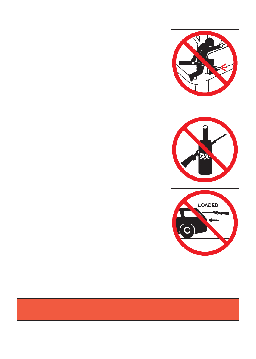
10. AVOID ALCOHOLIC BEVERAGES OR
JUDGMENT/REFLEX IMPAIRING MEDICATION
WHEN SHOOTING.
Do not drink and shoot. If you take medication that
can impair motor reactions or judgment, do not
handle a firearm while you are under the influence of
the medication.
11. NEVER TRANSPORT A LOADED FIREARM.
Unload a firearm before putting it in a vehicle
(chamber empty, magazine empty). Hunters and
target shooters should load their firearm only at their
destination, and only when they are ready to shoot.
If you carry a firearm for self-protection, leaving the
chamber unloaded can reduce the chance of an
unintentional discharge.
12. LEAD WARNING.
Discharging firearms in poorly ventilated areas, cleaning firearms, or handling
ammunition may result in exposure to lead and other substances known to cause
birth defects, reproductive harm, and other serious physical injury. Have
adequate ventilation at all times. Wash hands thoroughly after exposure.
9. NEVER CLIMB A TREE, FENCE OR OBSTRUCTION WITH A LOADED
FIREARM.
Open and empty the chamber(s) of your firearm and
engage the manual safety before climbing or
descending a tree or before climbing a fence or
jumping over a ditch or other obstruction. Never pull
or push a loaded firearm toward yourself or another
person. Always unload a firearm, visually and
physically check to see that the magazine, loading
mechanism and chamber are unloaded, and action is
open before handing it to another person. Never take
a firearm from another person unless it is unloaded,
visually and physically checked to confirm it is
unloaded, and the action is open.
WARNING: It is YOUR responsibility to know and abide by Federal, State and
Local laws governing the sale, transportation and use of firearms in your area.
Page 8
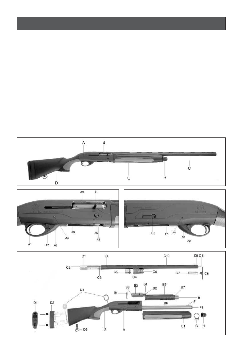
44
NOMENCLATURE
A Receiver
A1 Trigger
A2 Safety button
A3 Trigger guard
A4 Trigger plate retaining pin
A5 Breech bolt release button
A6 Carrier
A7 Carrier stop push button
A8 Loading gate
A9 Ejection port/cartridge chamber
A10 Cut-off
B Breech bolt assembly
B1 Cocking handle
B2 Extractor
B3 Breech bolt body
B4 Locking head with 2 lugs
B5 Operating rod with sleeve
B6 Recoil spring
B7 Piston retaining sleeve
B8 Firing pin
C Barrel
C1 Barrel breech
C2 Indexing lugs
C3 Locking shoulders
C4 Gas cylinder
C5 Piston with elastic seal
C6 Exhaust valve assembly
C7 Optimachoke
®
Plus choke tube
C8 Spanner for choke tube
C9 Truglo
®
front sight
C10 Top rib
C11 Muzzle
D Stock
D1 Gel•Tek recoil pad
D2 Kick Off
®
recoil absorber
D3 Rear sling swivel
D4 Drop/cast spacers
E Fore-end
E1 Fore-end flange with exhaust port
F Magazine tube
F1 Magazine tube cap
G Front sling swivel
H Fore-end cap
Page 9

45
The skilfully rounded receiver blends perfectly with the stock grip and permits for
instinctive, rapid target acquisition. Impeccable balance makes this shotgun easy to
point and fast-handling. The slim fore-end and the stock provide for an improved
ergonomic design that facilitates the mount of the shotgun. The sophisticated design
of the trigger guard elegantly merges with the receiver. The enlarged opening of the
trigger guard facilitates shooting when using gloves. The top of the receiver is
designed to accept optics and other aiming systems.
DESCRIPTION
MODERN AND STREAMLINED RECEIVER DESIGN
The stock and fore-end are produced in durable, resistant, anti-scratch fiberglass
reinforced technopolymer. The use of technopolymer ensures an improved feel in
cold weather and excellent color retention on a part typically subject to wear and tear.
Special soft plastic inserts are overmolded on the gripping areas of the stock and
fore-end to guarantee a secure grip in adverse weather conditions and absorb
vibrations when shooting.
STOCK AND FORE-END IN TECHNOPOLYMER
The A391 Xtrema2 features a rotating bolt with two locking lugs that engage the
barrel tang. The barrel tang includes two indexing lugs and a large surface contact
area with the receiver that minimize the barrel movement and improve accuracy.
The operating rods are integral to the bolt body, ensuring that it is guided
symmetrically and with minimal friction. The disassembly and reassembly of this unit
is also simplified.
ROTATING BOLT
Based on 40 years experience in manufacturing semiautomatic gas operated
shotguns, the new Beretta A391 Xtrema2 is born. Designed and conceived for the
use of Super Magnum 12 ga. 31/2” (89 mm) cartridges, it is also capable of functioning
with lighter cartridges.
Aqua Technology is the name given to the exclusive special surface and protective
treatments that are applied to the metal parts of the new Beretta A391 Xtrema2
shotgun. The steel barrel is chrome-plated inside to withstand the rigors of steel shot.
The external surface of the barrel is first blued and then covered with an exclusive
protective coating that remarkably increases its resistance to corrosion. The receiver
is made of black anodized aluminum alloy and also features the same protective
coating.
All the internal parts are either nickel or chrome plated, or they are protected by a
special process based on a ionic deposition which impregnates the surfaces with
ceramic compounds and metals (e.g. Titanium, Chrome) guaranteeing a great
resistance to wear and corrosion. This unique treatment, grey pearl in color, extends
to the breech bolt group, the trigger and the carrier. The main internal springs (recoil
spring, magazine tube spring, valve spring), the self-compensating valve and the rear
drop/cast plate are made of stainless steel.
The homogeneous matte black finish, which characterizes all the metal parts in view,
boasts anti-glare properties.
AQUA•TEK
Page 10

46
*NOTICE: Due to the precision machined tolerances on your Beretta shotgun,
some wear-in may be required before your new gun will function reliably with
light 28g (1 ounce, 31/4dram equivalent) game loads. If you experience any
initial functioning problems with these one-ounce loads, we recommend that
you fire three or four boxes of standard field loads to allow for this break-in
period.
The unique gas operation system, patented by Beretta, with self-cleaning gas
cylinder and piston, is provided with a self-cleaning exhaust valve that automatically
vents excess gases of the most powerful cartridges. The result is that the shotgun,
without any adjustment, operates with the weakest 28g (1 ounce, 31/4dram
equivalent) game load* to the heaviest 64g (21/4ounce) Super Magnum cartridge.
The exhaust valve remains attached to the barrel, ensuring easy and quick assembly
and disassembly of the shotgun.
GAS OPERATION SYSTEM WITH EXHAUST VALVE
BOLT TRAVEL RECOIL ABSORBER
A spring-mass recoil-reduction system, located inside the stock, counters the
rearward forces generated by shooting and greatly reduces felt recoil.
RECOIL REDUCTION SYSTEM
The new Beretta patented Kick Off®system (supplied with the A391 Xtrema2 Kick
Off®models) has been conceived to further reduce felt recoil when shooting. Thanks
to the Kick Off®device, the recoil energy is gradually dissipated by two hydraulic
absorbers (oil-operated) inserted into the stock. The result is superior comfort for the
shooter. At the same time, the vibrations and the muzzle jump when shooting are
strongly reduced. Long life, reliability and handling of the shotgun are therefore
guaranteed.
The standard A391 Xtrema2 model can accept the Kick Off®recoil absorber, that is
available as an accessory item.
KICK OFF®RECOIL ABSORBER
The A391 Xtrema2 is supplied with the Beretta Gel•Tek recoil pad. Its advanced
technology construction consists of a soft yet scratch resistant and durable polymer
shell and a recoil-absorbing silicone gel core. This non-toxic and inert gel distributes
the recoil effect over the entire pad surface, reducing the felt recoil and vibrations
transmitted to the shooter and it eliminates rubbing of the stock against the cheek.
By exchanging optionally available recoil pads of different thicknesses it is possible to
modify the length of pull.
GEL•TEK RECOIL PAD
The bolt travel recoil absorber is manufactured from an advanced elastomer that
reduces the stress caused by the breech bolt’s impact into the rear of the receiver
and simultaneously reduces the vibrations transmitted to the shooter. This also
contributes to the shotgun’s reliability durability and improved accuracy.
Page 11

47
The standard version of the Beretta A391 Xtrema2 comes equipped with a
technopolymer spacer, assembled between the stock and the Gel•Tek recoil pad.
The spacer is interchangeable with the other spacer included in the packaging in
order to have different lengths of pull. The length of pull can be varied from 13.18”
(335 mm) without any spacer assembled, to 14.66” (372.5 mm) with both spacers
assembled. The stock of the A391 Xtrema2 Kick Off®version is designed to accept
the optional 12.5 mm spacer only.
STOCK SPACERS
QUICK DETACHABLE SLING SWIVEL
The Optima-Bore®internal barrel profile features an overbored diameter and
lengthened forcing cone that considerably improve shot pattern distribution, felt recoil
reduction and shot velocity optimization.
OPTIMA-BORE®INTERNAL BARREL PROFILE
The Beretta Optimachoke®Plus tubes feature a long, gradual constriction, designed
to minimize shot deformation and to enhance the concentration and distribution of
shot patterns. They are engineered to resist steel shot stress and corrosion.
OPTIMACHOKE®PLUS CHOKE TUBES
The luminous optic fiber insert on the Truglo®front sight allows a precise aim even in
conditions of poor visibility. The luminous insert can be easily interchanged with
others in different color. The Truglo®front sight is supplied with the A391 Xtrema2
Kick Off®version. The classic metal front bead on the standard A391 Xtrema2 can be
replaced with an optional Truglo®front sight.
TRUGLO®LUMINOUS FRONT SIGHT
The cut-off control is positioned on the left side of the receiver: it can be engaged
when the breech bolt is in the closed position with the use of one hand. If the cut-off
is accidentally left engaged, automatic reloading after the first shot will disengage it.
CUT-OFF DEVICE
The design of the fiberglass reinforced technopolymer receiver-stock spacer and the
stock metal plate allows the stock drop and cast to be adjusted by simply modifying
their assembly position. Different stock drop and cast dimensions can be obtained
using the extra set of spacers supplied.
STOCK DROP AND CAST SPACERS
All the Beretta A391 Xtrema2 models come standard with front and rear swivel
attachments to fasten the carrying sling. Thanks to an exclusive quick-release
system it is possible to mount and remove the rear swivel from the stock without any
tools.
Page 12

48
The magazine tube is limited to 2 rounds, in compliance with sporting gun laws in
force in many countries, by the application of a reducer. Where it is legal, the
magazine tube capacity** (with magazine reducer removed) can be increased to
4/5 cartridges (70 mm – 23/4”), 4 cartridges (76 mm – 3”) or 3 cartridges (89 mm –
31/2”) .
An optional magazine extension is available.
*Number of rounds in the magazine plus round in the chamber.
** See “Ammunition” chapter
MAGAZINE CAPACITY*
The Beretta A391 Xtrema2 shotgun is supplied with a modern design case and a
complement of accessories: additional set of stock drop/cast plates (a set is already
mounted on the shotgun), 25 ml. Beretta Gun Oil, Optimachoke®Plus choke tubes
(one fitted in the barrel) with special spanner, 2 stock spacers with assembly screws
(standard version only) – one is mounted on the stock, 2 sling swivels and optic fiber
insert for Truglo®front sight (Kick Off®model only).
ACCESSORIES
NOTICE: There are numerous Beretta special parts and accessories that
allow the personalization of your firearm. To request this extensive line of parts
and accessories, please contact your local Beretta dealer.
Page 13

49
TECHNICAL FEATURES AND D ATA
* See Ammunition chapter
** Weights are approximate, dependent on barrel length.
Gauge 12
Cartridge chamber Universal (from 2
3
/4” to 3 1/2”)
Operation Semiautomatic, gas operation with exhaust
valve mounted on the barrel
Locking system Breech bolt with rotating head
Receiver Aluminum alloy with bolt travel elastomer
recoil absorber
Barrel
Alloyed steel, chromium-plated bore and
chamber
Rib Ventilated
Front sight Metal bead or Truglo
®
luminous front sight
Safety Cross bolt
Magazine capacity* Plugged to 2
Stock, fore-end High strength fiber glass reinforced
technopolymer with Recoil Reduction System
and Gel•Tek recoil pad. Adjustable drop.
Cast-off or cast-on.
Length of pull Standard model: 13.18” ÷ 14.66”
(335 mm÷372.5 mm)
Kick Off
®
model: 14.25” (362 mm)
Weight approx.** 7.6 Lbs./3.450 kg (Standard model)
7.8 Lbs./3.550 kg (Kick Off
®
model)
Page 14

50
ASSEMBLY OF THE PACKED SHO TGUN
WARNING: THIS FIREARM HAS THE CAPABILITY OF TAKING YOUR LIFE
OR THE LIFE OF SOMEONE ELSE! ALWAYS BE EXTREMELY CAREFUL
WITH YOUR FIREARM. AN ACCIDENT IS ALMOST ALWAYS THE RESULT
OF NOT FOLLOWING BASIC FIREARM SAFETY RULES.
WARNING: Beretta assumes no responsibility for any injury or property
damage resulting from improper or careless handling, intentional or accidental
discharge of the firearm.
WARNING: All assembly, disassembly and maintenance procedures should
be carried out with the firearm unloaded (magazine tube empty, receiver
empty and cartridge chamber empty). Check that the firearm is unloaded by
looking through the ejection port, the loading gate and the chamber.
WARNING: During the assembly, disassembly and maintenance procedures,
never point a firearm at someone or at hard and flat surfaces. Treat the
firearm as if it were loaded. (See points 1, 2 and 4 of the BASIC SAFETY
RULES).
The Beretta A391 Xtrema2 semiautomatic shotgun is packed from the factory with
the barrel separate from the stock/receiver/fore-end assembly.
Assemble the barrel to the stock/receiver/fore-end unit as follows:
NOTICE: It is advisable to carry out the assembly operations over a table to
catch components should they drop.
CAUTION: If, for any reason, the breech bolt is open and the fore-end is
separated from the stock/receiver assembly, avoid pressing the breech bolt
release button and be careful to keep your fingers away from the ejection port.
Should the breech bolt release button be pressed in this condition, the breech
bolt would slam forward and would stop only when the cocking handle hits the
forward rim of the ejection port. This could damage both the handle and the
receiver.
●
Check the barrel. The bore and chamber must be clean and free from obstructions.
●
Unscrew (counterclockwise) the fore-end cap from the stock/receiver/fore-end
assembly (Fig. 1).
●
Pull the fore-end off the magazine tube (Fig. 2).
●
Ensure that the piston is positioned inside the barrel gas cylinder (Fig. 3). If the
piston is mounted on the magazine tube, remove it and insert it in the barrel
cylinder; gently squeeze the elastic seal with your fingers in order to facilitate the
insertion of the piston into the cylinder (Fig. 4).
NOTICE: The numbers in the figures refer to the photos on pages 108, 109,
110 and 111.
Page 15

51
CAUTION: Should the breech bolt release button be pressed in this condition,
the breech bolt would slam forward and would stop only when the cocking
handle hits the forward rim of the ejection port. This could damage both the
handle and the receiver.
CAUTION: While depressing the breech bolt release button to close the
breech bolt, make sure that the cut-off is not inadvertently engaged. Should
this occur, the breech bolt would be kept OPEN by the cut-off lever. In this
case, always keeping your fingers away from the ejection port, close the
breech bolt by operating the cut-off (Fig. 12).
●
Check that the carrier stop push button is completely depressed. If not, depress it
completely (Fig. 5).
●
Pull the cocking handle backward to bring the breech bolt in the OPEN position
(Fig. 6). If the hammer is not cocked and the safety is engaged (Fig. 13/b) the
breech bolt cannot be retracted.
●
Partially slide the barrel into the receiver, taking care that the magazine tube enters
the piston hole as well as that of the gas cylinder and the valve assembly (Fig. 7).
●
Slide the barrel home into the receiver (Fig. 8).
●
Slide the fore-end into place over the gas cylinder, valve assembly and magazine
tube. Check that the fore-end is perfectly centered on the receiver face (Fig. 9).
The fore-end is correctly positioned when its rearward edge seats around the
receiver.
●
Place the supplied front swivel ring on the fore-end flange (if desired) and
completely tighten the fore-end cap (Fig. 10). Ensure that the swivel is able to
freely rotate on its axis.
●
Close the breech bolt by depressing the breech bolt release button, keeping your
fingers away from the ejection port (Fig. 11).
●
Depress the trigger to lower the hammer.
●
Engage the safety by pushing the safety button until the red ring disappears
(Fig. 13-13/b).
WARNING: The manual safety is merely a mechanical device and is in no
way a substitute for the Basic Safety Rules of firearm handling.
WARNING: Do not store firearms in places which are or could be accessible
by children or other persons whose unfamiliarity with firearms might lead to
unsafe use. Always store your firearms securely and unloaded, separate from
ammunition (See point 3 of the BASIC SAFETY RULES).
Page 16

52
LO AD CHECK
At various parts in this manual, you are instructed to visually inspect the ejection port,
the loading gate and the cartridge chamber and to make sure your Beretta A391
Xtrema2 is unloaded. This operation as well as the precautions below become
second nature:
●
Never assume that the shotgun is unloaded.
●
Never point or push the shotgun toward yourself or another person.
●
Always visually inspect the ejection port, the loading gate and the cartridge
chamber to make sure they are empty. The cartridge chamber is the portion of the
barrel into which the cartridge is fed (Fig. 14).
●
Before handing the shotgun to anyone else, pull the cocking handle backward to
bring the breech bolt in the OPEN position and engage the safety.
●
Never take or pull the shotgun from anyone else unless the breech bolt has been
opened, and the ejection port, the loading gate and the cartridge chamber have
been visually inspected to make sure they are empty.
Proceed as follows to visually inspect the ejection port, the loading gate and the
cartridge chamber.
WARNING: Always keep your finger off the trigger and the barrel pointed in a
safe direction.
●
Check that the carrier stop push button is completely depressed. If not, depress it
completely (Fig. 5).
●
Pull the cocking handle backward to bring the breech bolt in the OPEN position
(Fig. 6). If the hammer is not cocked and the safety is engaged the breech bolt
cannot be retracted.
●
Engage the safety by pushing the safety button until the red ring disappears
(Fig. 13-13/b).
●
Look through the ejection port, the loading gate and the cartridge chamber. They
must be completely empty. If not, unload them by proceeding as indicated in the
chapter: “Unloading the firearm “.
●
Close the breech bolt by depressing the breech bolt release button, keeping your
fingers away from the ejection port (Fig. 11).
●
Disengage the safety and depress the trigger to lower the hammer.
Page 17

53
OBSTRUCTION CHECK
WARNING: Always make sure the shotgun in unloaded. Refer to the
instructions in the section: ” LOAD CHECK”.
WARNING: Beretta assumes no responsibility for physical injury or property
damage resulting from the use of defective, improper, hand-loaded, reloaded
or remanufactured ammunition. Serious damage and injury, and even death,
could result from the use of incorrect ammunition, from firing against bore
obstructions and from propellant overloads.
Visually inspect the barrel to make sure there are no obstructions in the barrel and
chamber. This operation is extremely important because if another cartridge is fired
with the barrel or chamber obstructed, a catastrophic failure can result.
●
Check that the carrier stop push button is completely depressed. If not, depress it
completely (Fig. 5).
●
Pull the cocking handle backward to bring the breech bolt in the OPEN position
(Fig. 6). If the hammer is not cocked and the safety is engaged the breech bolt
cannot be retracted.
●
Engage the safety by pushing the safety button until the red ring disappears
(Fig. 13-13/b).
●
Following the instructions given in the paragraph: “Disassembly” remove the foreend and the barrel and look down through the barrel from the rear end and make
sure there are no obstructions, even minor ones.
If an obstruction in the barrel is detected, a qualified gunsmith must remove the
obstruction and inspect the shotgun before it can be fired.
●
Reassemble barrel and fore-end as described in the paragraph “Reassembly”.
●
Close the breech bolt by depressing the breech bolt release button, keeping your
fingers away from the ejection port (Fig. 11).
●
Disengage the safety and depress the trigger to lower the hammer.
AMMUNITION
The Beretta A391 Xtrema2 semi-automatic shotgun features a 31/2” (89 mm)
chamber. You will find the markings for the gauge and chamber length for your
shotgun on the side of the barrel. Every gun has been tested with special proof test
ammunition.
The shotgun, without any adjustment, fires everything from the weakest 28 g.
(1 ounce, 31/4dram equivalent) game load* to the heaviest 64 g. (21/4ounce) Super
Magnum cartridge.
Page 18

54
*NOTICE: Due to the precision machined tolerances on your Beretta shotgun,
some wear-in may be required before your new gun will function reliably with
light 28 g (1 ounce, 31/4dram equivalent) game loads. If you experience any
initial functioning problems with these one ounce loads, we recommend that
you fire three or four boxes of standard field loads to allow for this break-in
period.
WARNING: Never use cartridges that do not correspond to the markings on
the side of the barrel.
WARNING: Use cartridges whose length corresponds or it is inferior to the
chamber length indicated on the side of the barrel.
WARNING: To avoid use of improper ammunition, check markings on the
cartridge box and on the cartridge itself to ensure that the correct gauge and
length of shell is used for your firearm.
STEEL SHOT
Beretta “SP” (Steel Proof) Optimachoke®Plus tubes are designed for use also with
factory steel shot cartridges loaded to standard specifications. When firing steel shot
cartridges with the Optimachoke®Plus tubes, the best results are obtained using
open chokes (C0000/CL, 0000/IC, 000/M). Use of tight choke constrictions (0/F,
00/IM) when utilizing steel shot, do not increase pattern density and will distort
normal pattern density. Additionally, use of tight constrictions when shooting steel
shot increases wear and tear of the choke tube and can decrease pattern efficiency
or cause “blown patterns”. See also the paragraph Beretta Optimachoke®Plus tubes.
MAGAZINE CAPACITY
The magazine tube of the A391 Xtrema2 has been limited to two rounds by the
application of a plug in order to comply with the sporting gun laws in force in many
countries.
This plug, which is factory mounted, reduces the capacity of the A391 Xtrema2 to no
more than three rounds (two in the magazine, one in the chamber).
In the countries where it is allowed, it is possible to increase the magazine capacity to
4/5 rounds (23/4” – 70 mm cartridges), 4 rounds (3” – 76 mm cartridges) or 3 rounds
(3 1/2” – 89 mm cartridges).
NOTICE: Where allowed by law, an optional magazine tube extension may be
purchased. This will increase the magazine capacity to 7 rounds (if using 2 3/4”
shells), 6/7 rounds (if using 3” shells) or 5 rounds (if using 3 1/2” shells).
NOTICE: These operations must be carried out by a competent gunsmith.
NOTICE: Wholesalers, dealers or gunsmiths (unless they are a Repair Station
authorized by the Manufacturer and/or by its Local Official Distributors) are not
authorized to make any Warranty repair or adjustment on behalf of the
Manufacturer.
Page 19

55
LO ADING THE FIREARM
WARNING: Before loading the firearm, practice the following loading
procedures without the use of ammunition. Never handle a loaded firearm until
you are fully familiar with the loading procedures. Check that the firearm is
unloaded by looking through the ejection port, the loading gate and the
chamber. Before loading the shotgun, make sure that the safety is engaged.
Always point the firearm in a safe direction. (See points 1, 2 and 4 of the
BASIC SAFETY RULES). Always check the barrel prior to loading to ensure
that it is clean and free from obstructions.
WARNING: The shooter and bystanders must always wear eye and hearing
protection. Particles of shot, lead, powder, lubricant, etc. may cause injury to
persons. Hearing protection reduces the risk of hearing damage caused by
exposure to shooting noise.
WARNING: Always keep your fingers away from the trigger and keep the
trigger free from any contact when you do not intend to fire.
NOTICE: If the hammer is de-cocked and the safety is engaged, it is not
possible to retract the breech bolt.
●
Disengage the safety by pushing the safety button until the red ring appears
(Fig. 15).
WARNING: When the safety button shows the red ring, the safety is
disengaged and the firearm is in the FIRE position.
WARNING: The manual safety is merely a mechanical device and is in no
way a substitute for the Basic Safety Rules.
WARNING: The firearm is now loaded and, once the safety is disengaged,
READY TO FIRE. Always keep your fingers away from the trigger and keep
the trigger free from any contact when you do not intend to fire. Never point
the firearm at something that is not safe to shoot. (See points 1, 2 and 4 of the
BASIC SAFETY RULES).
●
Check that the carrier stop push button is completely depressed. If not, depress it
completely (Fig. 5).
●
Pull the cocking handle backward to bring the breech bolt in the OPEN position
(Fig. 6).
●
Engage the safety by pushing the safety button until the red ring disappears
(Fig. 13-13/b).
●
Insert the first round into the barrel chamber through the ejection port (Fig. 16).
●
Depress the breech bolt release button to lock the breech bolt, keeping fingers
away from the ejection port.
Page 20

56
NOTICE: The manufacturer assumes no responsibility for any injury or
property damage resulting from improper or careless handling, intentional or
accidental discharge of the firearm.
CAUTION: Should the breech bolt remains open, check that the cut-off is not
inadvertently engaged. If it is, always keeping your fingers away from the
ejection port, close the breech bolt by operating the cut-off button (Fig. 12).
●
Insert through the loading gate the other cartridges by placing each round on the
carrier and pressing it down and forward into the magazine tube until it engages
the stop tooth (Fig. 17).
●
To fire, disengage the safety and pull the trigger.
●
After firing the first cartridge, release the trigger completely to re-set the gun for the
next shot.
●
The gun will fire first the cartridge in the chamber and then automatically feed in the
cartridge from the magazine tube.
WARNING: If the gun does not fire on a live cartridge when the trigger is
pulled, activate the safety, wait one minute, then unload the firearm as
described in the chapter “ Unloading the firearm”. Never attempt to fire
ammunition that did not fire the first time. Dispose of misfire or faulty
ammunition properly according to the cartridge manufacturer’s
recommendations.
WARNING: If a cartridge is fired into an obstructed barrel, a catastrophic
failure can result.
WARNING: Always unload the firearm immediately after completing shooting.
Never store a loaded firearm. Storage instructions refer to the section:
“Storage”.
If you do not intend to fire the second cartridge, engage the safety with the gun
pointed in a safe direction and your fingers away from the trigger. If you have finished
firing, unload the shotgun as described in the chapter “ Unloading the firearm”.
●
When the last round has been fired, the breech bolt remains open, thus signalling
that the magazine is empty (Fig. 18).
●
Engage the safety and, if required, reload the firearm as previously indicated.
Page 21

57
USE OF THE CUT-OFF DEVICE
UNLO ADING THE FIREARM
The cut-off device allows to extract a live round from the cartridge chamber and lock
the breech bolt open for safety or to replace the round in the chamber, without
feeding a new round from the magazine.
WARNING: The firearm is now loaded with a cartridge in the chamber and the
safety engaged. Never point a firearm at something that is not safe to shoot.
(See points 1, 2 and 4 of the BASIC SAFETY RULES).
WARNING: The firearm is loaded and, once the safety is disengaged, ready
to fire again. Make sure that the safety is fully engaged. Never point a firearm
at something that is not safe to shoot. (See points 1, 2 and 4 of the BASIC
SAFETY RULES).
WARNING: The firearm is loaded and ready to fire. Always keep your fingers
away from the trigger and keep the trigger free from any contact when you do
not intend to fire. Never point a firearm at someone or at hard and flat
surfaces. (See points 1, 2 and 4 of the BASIC SAFETY RULES).
●
Make sure that the safety is engaged (warning red ring covered) (Fig. 13/b).
●
Engage the cut-off by depressing the cut-off lever (round side) on the left side of
the receiver (Fig. 19).
●
Retract the breech bolt by means of the cocking handle to extract the live round
from the cartridge chamber and eject it through the ejection port. At the end of its
travel, the breech bolt is hooked into the OPEN position by the carrier which is
locked by the cut-off device. Feeding from magazine is blocked (Fig. 20).
●
Under safety conditions, insert the extracted cartridge or another cartridge into the
chamber.
●
Keeping fingers away from the ejection port, depress the cut-off lever to close the
breech bolt (Fig. 12).
●
To fire, disengage the safety and pull the trigger.
NOTICE: If the firearm is to function properly, it is recommended that the cutoff be used as described above. In particular, it must be remembered that the
breech bolt, when held OPEN by the cut-off, can be closed only by operating
the cut-off lever.
●
Pointing the firearm in a safe direction, check that safety is engaged (red ring
covered).
●
Engage the cut-off (Fig. 19) and retract the breech bolt to extract and eject the
chambered live round (Fig. 20).
●
Keeping fingers away from the ejection port, depress the cut-off lever to close the
breech bolt (Fig. 12).
Page 22

58
●
Pressing down the carrier and, at the same time, pushing against the cartridge in
the magazine, depress the breech bolt release button to ease exit of the shells
from the magazine tube.
●
Check to ensure the magazine tube and receiver are empty. Disengage the safety.
Be careful where you point the firearm, even though it might not be loaded.
●
Pull the trigger to lower the hammer.
●
Engage the safety by pushing the safety button until the red ring disappears
(Fig. 13-13/b).
WARNING: The manual safety is merely a mechanical device and is in no
way a substitute for the Basic Safety Rules of firearm handling.
WARNING: Check the firearm is unloaded (cartridge chamber empty, receiver
empty, magazine tube empty). Check that the firearm is unloaded by looking
through the ejection port, the loading gate and the chamber. If the shotgun is
not unloaded, unload it as described in the chapter “Unloading the firearm”.
Lower the hammer on the unloaded gun by pulling the trigger.
WARNING: Never point a firearm at someone or at hard and flat surfaces.
Treat the firearm as if it were loaded. (See points 1, 2 and 4 of the BASIC
SAFETY RULES).
DISASSEMBLY
NOTICE: It is advisable to carry out the field stripping operations over a table
to catch components should they drop.
NOTICE: If the hammer is de-cocked and the safety is engaged, it is not
possible to retract the breech bolt.
BARREL
●
Disengage the safety by pushing the safety button until the red ring appears
(Fig. 15).
●
Check that the carrier stop push button is completely depressed. If not, depress it
completely (Fig. 5).
●
Pull the cocking handle backward to bring the breech bolt in the open position.
●
Unscrew (counterclockwise) the fore-end cap from the firearm and remove the
front swivel, if present (Fig. 21).
●
With one hand hold the barrel down and with the other hand slide the fore-end off
the magazine tube (Fig. 9).
●
Grasping the barrel and holding the piston inside the gas cylinder, slide the barrel
forward off the stock/receiver assembly (Fig. 7).
●
Slide the piston off the gas cylinder (Fig. 22).
Page 23

59
NOTICE: NEVER DISASSEMBLE the valve spring or the valve spring
retaining ring. The valve is self-cleaning and as such does not require
maintenance. In case disassembly is required, please consult a competent
gunsmith.
NOTICE: Disassembly of the breech bolt assembly is advisable only when it
becomes necessary to clean its individual components. This may become
necessary after 500-1000 shots, depending on ammunition used, or at the end
of the season before the gun is to be stored for an extended period of time.
NOTICE: Disassembly of the trigger group is advisable only when it becomes
necessary to clean the trigger mechanism. This may be necessary after 5001000 shots, depending on ammunition used, or at the end of the season
before the gun is to be stored for an extended period of time (See “Special
Maintenance”).
BREECH BOLT ASSEMBLY
(Breech bolt, operating rods with sleeve, recoil spring and piston retaining sleeve).
●
Holding the cocking handle with the index or middle finger of the left hand, depress
the breech bolt release button and allow the breech bolt to slide slowly forward until
it stops (Fig. 23).
●
Press the bolt head until the index mark on its neck corresponds to the edge of the
bolt body (Fig. 24).
●
Keeping the bolt head depressed in this position, remove the bolt handle by pulling
it out with force (Fig. 25).
●
Holding the stock/receiver assembly on a table with the ejection port facing
upward, slide the operating rods sleeve forward off the magazine tube to extract
the breech bolt assembly from the receiver (Fig. 26).
TRIGGER PLATE
SLING SWIVELS
●
Engage the safety (the hammer is cocked).
●
Check that the carrier stop push button is completely depressed. If not, depress it
completely (Fig. 5).
●
Push out the trigger plate retaining pin by pressing it with a drift punch or other
similar tool (Fig. 27).
●
Keeping the breech bolt release button pressed, extract the trigger plate by pulling
on the trigger guard with a forward and downward movement (Fig. 28).
How to detach the rear sling swivel
The quick detachable rear sling swivel can be rapidly mounted or removed from the
stock.
Proceed as indicated:
●
Completely press with your finger the release button at the top of the swivel body
and insert the swivel in its seat on the stock (Fig. 29).
●
To extract the swivel, keep the release button pressed and completely extract the
swivel from the stock.
Page 24

60
Beretta’s Optimachoke®Plus Designations
Standard Markings American Choke Tube Compatibility Extra Long
Designation With Steel Shot Tube
0 (*) F (Full) SP
(1)
I
00(**) IM (Improved Modified) SP
(1)
II
000(***) M (Modified) SP III
0000(****) IC (Improved Cylinder) SP IIII
C0000(C****) CL (Cylinder) SP IIIII
(1) Not recommended for use of Steel Shots.
Optimachoke®is a registered trademark of Fabbrica d’Armi Pietro Beretta S.p.A.
Special Optimachoke®Plus chokes for different uses are available in selected markets.
CAUTION: Further disassembly of the firearm is not recommended, unless
carried out by a competent gunsmith.
NOTICE: Wholesalers, dealers or gunsmiths (unless they are a Repair Station
authorized by the Manufacturer and/or by its Local Official Distributors) are not
authorized to make any Warranty repair or adjustment on behalf of the
Manufacturer.
BERETTA OPTIMACHOKE®PLUS
TUBES
Beretta Optimachoke®Plus choke tubes are made of high-grade steel for corrosion
resistance and durability. They are designed to withstand the rigors of non-toxic steel
shot.
WARNING: The barrel of your A391 Xtrema2 will only accept Optimachoke
®
Plus chokes.
WARNING: Never look into the muzzle or change tube on a loaded gun, even
with safety engaged.
WARNING: Check the firearm is unloaded (cartridge chamber empty, receiver
empty, magazine tube empty). Check that the firearm is unloaded by looking
through the ejection port, the loading gate and the chamber. If the shotgun is
not unloaded, unload it as described in the chapter “Unloading the firearm”.
Lower the hammer on the unloaded gun by pulling the trigger.
REMOVAL OF THE CHOKE TUBE
How to remove the front sling swivel
The front swivel can be easily mounted or removed from the fore-end by
disassembling the fore-end cap.
Page 25

61
●
Unscrew (counterclockwise) the choke using the supplied spanner (Fig. 30).
●
Remove the choke from the muzzle (Fig. 31).
CLEANING OF THE CHOKE TUBE AND ITS HOUSING
INSTALLATION OF THE CHOKE TUBE
WARNING: Check the firearm is unloaded (cartridge chamber empty, receiver
empty, magazine tube empty). Check that the firearm is unloaded by looking
through the ejection port, the loading gate and the chamber. If the shotgun is
not unloaded, unload it as described in the chapter “Unloading the firearm”.
Lower the hammer on the unloaded gun by pulling the trigger.
WARNING: Never look into the muzzle or change tube on a loaded gun, even
with safety engaged.
●
Carefully clean the choke housing. If necessary, use a cotton patch coated with
Beretta Gun Oil. Dry the choke housing using a soft patch.
●
Check the choke to make sure it is perfectly clean inside and outside.
●
Apply a thin coat of Beretta Gun Oil to the thread of the barrel and of the choke
tube.
WARNING: Check the firearm is unloaded (cartridge chamber empty, receiver
empty, magazine tube empty). Check that the firearm is unloaded by looking
through the ejection port, the loading gate and the chamber. If the shotgun is
not unloaded, unload it as described in the chapter “Unloading the firearm”.
Lower the hammer on the unloaded gun by pulling the trigger.
WARNING: Never look into the muzzle or change tube on a loaded gun, even
with safety engaged.
CAUTION: Check that the choke tube is in perfect condition (not damaged)
prior installing it.
●
Check the choke and the thread of the barrel to make sure they are perfectly clean
and lightly oiled.
●
Insert the desired choke into the choke housing.
●
Carefully hand screw the choke into the barrel clockwise. Using the Beretta
spanner, tighten the choke until it is fully bottomed into its recess in the barrel.
●
Remove the spanner after tightening.
WARNING: Periodically check, under safe conditions (cartridge chamber
empty, receiver empty, magazine tube empty and breech bolt in OPEN
position) whether the choke is fully and tightly set into the barrel. If necessary,
firmly tighten the choke, using the Beretta spanner, until it can be tighten no
more. This tightening is needed to avoid damage to the barrel and to avoid
propelling the choke out of the muzzle when the gun is fired, which may cause
damage to the gun or injury to persons.
Page 26

62
WARNING: The choke tube must be kept correctly tightened in the barrel at
all times, even during storage and cleaning. Cleaning barrel with no choke
tube in place can push dirt into the barrel thread, causing improper choke
installation, rusting, or barrel obstruction.
WARNING: Never shoot choke barrel without using choke tube. Shooting
without choke tube is very dangerous as debris could be trapped by the thread
and create barrel obstructions. It may also cause erratic shot pattern and can
damage the barrel’s internal screw thread irreparably.
Do not alter or modify existing fixed choke Beretta barrel for the use of
interchangeable choke tubes. The resulting wall thickness would be too thin to
safely contain the pressure levels generated by shooting.
ROUTINE MAINTENANCE
When combustion residues, grease or dirt particles have accumulated in the action,
clean and lubricate the firearm.
Cleaning and lubrication of the shotgun after use is the best guarantee for protection
of parts against corrosion deriving from combustion residues and from use of the
firearm in humid or saline environments.
At the end of the hunting or shooting day, perform the Routine Maintenance as
indicated.
WARNING: Check the firearm is unloaded (cartridge chamber empty, receiver
empty, magazine tube empty). Check that the firearm is unloaded by looking
through the ejection port, the loading gate and the chamber. If the shotgun is
not unloaded, unload it as described in the chapter “Unloading the firearm”.
Lower the hammer on the unloaded gun by pulling the trigger.
WARNING: Never point a firearm at someone or at hard and flat surfaces.
Treat the firearm as if it were loaded. (See points 1, 2 and 4 of the BASIC
SAFETY RULES).
CAUTION: To clean the shotgun, merely disassemble it following the
procedure described in the relevant section.
BARREL
●
After use, thoroughly clean the barrel bore by passing a swab through it to remove
combustion residues. If necessary, use a cleaning rod with bronze brush and/or a
patch soaked in a bore cleaning solvent.
●
Thoroughly clean the locking shoulders on the barrel breech.
●
Pull a clean soft patch through the barrel bore.
●
Lightly lubricate the barrel bore by pulling through it a soft clean patch treated with
Beretta Gun Oil.
●
Check the barrel and the cartridge chamber to ensure that they are clean and free
from obstructions.
Page 27

63
WARNING: Excess oil and grease obstructing the bore, even partially, are
very dangerous when firing and may cause damages to the shotgun and
serious injury to the shooter and bystanders. Never spray or apply oil to the
cartridges. Use lubricants properly: you are responsible for the proper care
and maintenance of the firearm.
GAS CYLINDER, PISTON, MAGAZINE TUBE
EXHAUST VALVE ASSEMBLY
CAUTION: Magnum cartridges and particularly Super Magnum shotshells
produce a high amount of combustion gases. The particular composition of
some Super Magnum shotshells’ powder can generate a strong deposit of
combustion residues. The parts of the shotgun which, coming into contact with
the gases, are more affected by the combustion residues are the gas cylinder
(inside), the piston with its elastic seal, and the magazine tube.
CAUTION: Do not oil these parts.
NOTICE: Never disassemble the compensating valve assembly. If this
becomes necessary, please consult a competent gunsmith.
●
Carefully clean the piston, the elastic seal and the magazine tube with a soft brush
sprayed with Beretta Gun Oil.
●
Ensure that the piston can freely move along the magazine tube.
●
Carefully clean the inner side of the gas cylinder with a bronze brush sprayed with
Beretta Gun Oil.
●
When all combustion residues are removed, clean the inside of the gas cylinder
with a soft cloth.
Page 28

64
FORE-END FLANGE
BREECH BOLT ASSEMBLY (Breech bolt, operating rods with sleeve, recoil
spring and piston retaining sleeve) (Fig. 32).
SPECIAL MAINTENANCE
Every 500 – 1000 rounds (according to the type of ammunition used) and in any case
at the end of the hunting season, before storing the shotgun, in addition to the
Routine Maintenance, also perform the following Special Maintenance operations.
●
Carefully clean the fore-end flange exhaust valve port with a soft brush sprayed
with Beretta Gun Oil. Carefully dry the flange with a soft cloth.
●
Thoroughly clean the parts with a small brush and Beretta Gun Oil.
●
Carefully dry with a soft cloth and lightly oil the parts with Beretta Gun Oil.
TRIGGER PLATE
RECEIVER
●
Thoroughly clean the parts with a soft cloth.
●
Lightly oil the metal parts and the trigger plate retaining pin.
●
Maintain as described for the breech bolt assembly. Carefully dry with a soft cloth
and lightly oil the slide rails of the breech bolt inside the receiver.
WARNING: Do not attempt to make repairs to any firearm without proper
knowledge or training. Do not alter parts or use substitute parts not made by
Beretta. Any alterations or adjustments that may be necessary to the
operating mechanism should be performed by the Manufacturer or by its Local
Official Distributor.
Page 29

65
WARNING: Check the firearm is unloaded (cartridge chamber empty, receiver
empty, magazine tube empty). Check that the firearm is unloaded by looking
through the ejection port, the loading gate and the chamber. If the shotgun is
not unloaded, unload it as described in the chapter “Unloading the firearm”.
Lower the hammer on the unloaded gun by pulling the trigger.
WARNING: Never point a firearm at someone or at hard and flat surfaces.
Treat the firearm as if it were loaded. (See points 1, 2 and 4 of the BASIC
SAFETY RULES).
REASSEMBLY
TRIGGER PLATE
●
Operate in reverse order to what is described in the chapter “Disassembly” making
sure that the hammer is cocked, the safety engaged and the carrier stop push
button depressed.
●
Insert the trigger plate retaining pin, ensuring that the trigger plate hole is centered
on the receiver hole.
●
Holding the stock/receiver assembly on a table with the ejection port facing
upward, slide the breech bolt, operating rods with sleeve, recoil spring and piston
retaining sleeve on the magazine tube and partially insert the breech bolt into the
receiver (Fig. 26).
●
Push the operating rod sleeve down until it seats against the receiver and the bolt
body is inside the receiver.
●
Press the bolt head until the index mark on its neck corresponds to the edge of the
bolt body.
●
Keeping the bolt head depressed in this position, push in the bolt handle until it
snaps into place (Fig. 25).
BARREL
●
Check the barrel and the cartridge chamber to ensure that they are clean and free
from obstructions.
●
Insert the piston into the gas cylinder, gently squeezing the elastic seal with your
fingers in order to facilitate the insertion of the piston into the cylinder (Fig. 4).
●
Check that the carrier stop push button is completely depressed. If not, depress it
completely (Fig. 5).
●
Pull the cocking handle backward to bring the breech bolt in the OPEN position
(Fig. 6).
BREECH BOLT ASSEMBLY (Breech bolt, operating rods with sleeve, recoil
spring and piston retaining sleeve).
Page 30

66
WARNING: Do not store firearms in places which are or could be accessible
by children or other persons whose unfamiliarity with firearms might lead to
unsafe use. Always store your firearms securely and unloaded, separate from
ammunition. (See point 3 of the BASIC SAFETY RULES).
CAUTION: It is recommended to store the firearm disassembled (See
paragraph Storage).
CAUTION: Should the breech bolt release button be pressed in this condition,
the breech bolt would slam forward and would stop only when the cocking
handle hits the forward rim of the ejection port. This could damage both the
handle and the receiver.
●
Partially slide the breech barrel into the receiver, taking care that the magazine
tube enters the piston hole as well as that of the gas cylinder and the valve
assembly (Fig. 7).
●
Slide the barrel home into the receiver (Fig. 8).
●
Slide the fore-end into place over the gas cylinder, valve assembly and magazine
tube. Check that the fore-end is perfectly centered on the receiver face (Fig. 9).
The fore-end is correctly positioned when its rearward edge seats around the
receiver.
●
Place the front swivel ring on the fore-end flange (if desired) and completely tighten
the fore-end cap (Fig. 10). Ensure that the swivel is able to freely rotate on its axis.
●
Close the breech bolt by depressing the breech bolt release button, keeping your
fingers away from the ejection port (Fig. 11).
CAUTION: While depressing the breech bolt release button to close the
breech bolt, make sure that the cut-off is not inadvertently engaged. Should
this occur, the breech bolt would be kept OPEN by the cut-off lever. In this
case, always keeping your fingers away from the ejection port, close the
breech bolt by operating the cut-off (Fig. 12).
●
Depress the trigger to lower the hammer.
●
Engage the safety by pushing the safety button until the red ring disappears
(Fig. 13-13/b)
WARNING: The manual safety is merely a mechanical device and is in no
way a substitute for the Basic Safety Rules of firearm handling.
Page 31

67
WARNING: Check the firearm is unloaded (cartridge chamber empty, receiver
empty, magazine tube empty). Check that the firearm is unloaded by looking
through the ejection port, the loading gate and the chamber. If the shotgun is
not unloaded, unload it as described in the chapter “Unloading the firearm”.
Lower the hammer on the unloaded gun by pulling the trigger.
WARNING: Never point a firearm at someone or at hard and flat surfaces.
Treat the firearm as if it were loaded. (See points 1, 2 and 4 of the BASIC
SAFETY RULES).
GEL•TEK RECOIL PAD
The standard Gel•Tek recoil pad can be replaced with other Beretta recoil pads of
different thickness and material (optional). By exchanging optionally available recoil
pads of different thicknesses it is possible to modify the length of pull.
TO REMOVE THE GEL•TEK RECOIL PAD
TO REASSEMBLE THE GEL TEK RECOIL PAD
●
With a flathead screwdriver (approx. 4 mm/0.2”), pull out retaining clasp of the
Gel•Tek recoil pad (Fig. 33).
●
Remove the Gel•Tek recoil pad (Fig. 34).
●
With a flathead screwdriver (approx. 4 mm/0.2”), pull out retaining clasp of the
Gel•Tek recoil pad.
●
Place the pad on the Kick Off®recoil absorber or on the stock insert (standard
version) and make sure that all bushings are placed in the proper holes.
●
While securely pushing the pad against the stock, push retaining clasp back, until it
disappears in the pad assembly (Fig. 35). Be sure that the pad fits flush to the
stock without movement.
Page 32

68
ST OCK SPACERS
WARNING: Check the firearm is unloaded (cartridge chamber empty, receiver
empty, magazine tube empty). Check that the firearm is unloaded by looking
through the ejection port, the loading gate and the chamber. If the shotgun is
not unloaded, unload it as described in the chapter “Unloading the firearm”.
Lower the hammer on the unloaded gun by pulling the trigger.
WARNING: Never point a firearm at someone or at hard and flat surfaces.
Treat the firearm as if it were loaded. (See points 1, 2 and 4 of the BASIC
SAFETY RULES).
The standard model of the A391 Xtrema2 (not supplied with the Kick Off®recoil
absorber) comes with the 25mm spacer already mounted between the stock insert
and the Gel•Tek recoil pad. In order to increase the length of pull it is possible to also
add the supplied 12.5mm thin spacer. The thin spacer is included in the packaging of
the standard version only. If you wish to reduce the length of pull remove the thick
spacer or replace it with the thin spacer. The Kick Off®model can accept the optional
12.5mm spacer only.
NOTICE: The Standard version (i.e. non-Kick Off®) comes with a 12.5 mm
spacer and a 25 mm spacer with their screws. The short screws allow the
attachment of the 12.5 mm spacer. When mounting the 25 mm spacer or both
spacers use the long screws. The Kick Off®model can accept the optionally
available 12.5 mm spacer only.
To disassemble and reassemble the spacer proceed as indicated:
●
Remove the Gel•Tek recoil pad as described in the previous paragraph.
●
Unscrew and remove the retaining screws and the bushings from the stock, using
a Phillips-head screwdriver (Fig. 36).
●
Remove the mounted spacer, replace it, or add the other one.
●
Insert bushings in their lodgings in the stock and securely tighten all screws using a
properly sized Phillips-head screwdriver.
●
Remount the Gel•Tek recoil pad on the stock as described in the previous
paragraph.
Page 33

69
ST OCK DROP AND CAST
MODIFICATION
WARNING: Check the firearm is unloaded (cartridge chamber empty, receiver
empty, magazine tube empty). Check that the firearm is unloaded by looking
through the ejection port, the loading gate and the chamber. If the shotgun is
not unloaded, unload it as described in the chapter “Unloading the firearm”.
Lower the hammer on the unloaded gun by pulling the trigger.
WARNING: Never point a firearm at someone or at hard and flat surfaces.
Treat the firearm as if it were loaded. (See points 1, 2 and 4 of the BASIC
SAFETY RULES).
The Beretta A391 Xtrema2 is factory set with a heel drop of 55 or 60 mm (2.16” or
2.36” ) and cast-off (right-handed shooters).
The components, which determine the drop and the cast, are: (see drawing next
page)
➀ A receiver-stock spacer made of fiberglass reinforced technopolymer.
➁ A metal stock plate.
Both the spacer ➀ and the plate ➁ are designed to secure two different drops with
cast-off or with cast on (for left-handed shooters) depending on how they are
assembled. Other measures of stock drop can be obtained using the supplied extra
set of spacer/plate.
CHANGING THE STOCK DROP AND CAST SPACER/PLATE
NECESSARY TOOLS
NOTICE: The “DX” mark on the spacer/plate means “cast-off”, the “SX” mark
means “cast-on”. The stock drop measures are in millimeters. The stock drop
and cast of the front spacer ➀ must always correspond to those of the rear
plate ➁.
WARNING: Stock modifications for drop and cast must be carried out by a
competent gunsmith. The improper observance of the following procedures
could cause damage to the shotgun and/or injury to the bystanders.
●
Screwdriver.
●
Hexagonal spanner (6 mm)
●
Hexagonal tube spanner (13 mm).
●
Torque wrench (suggested).
Page 34

70
DISASSEMBLY
●
Remove the rear sling swivel (see
disassembly section).
●
Using a 6mm hexagonal key completely
unscrew the swivel bushing inserted in
the stock (Fig. 37). Remove the bushing
from the stock.
●
Remove the Gel•Tek recoil pad, its screws
and bushings from the stock insert or Kick
Off®recoil absorber (See the appropriate
paragraphs) (Fig. 36).
●
Remove the stock spacer, if present.
●
Using the 13mm hexagonal tube spanner completely
unscrew and remove the retaining nut with its washer from the
stock.
●
Remove the Kick Off®recoil absorber (Kick Off®model) or the stock
insert (standard model).
●
Remove the internal metal plate ➁, positioned in the Kick Off®body or in
the stock insert.
●
Separate the stock from the receiver and remove the technopolymer front
spacer ➀.
REASSEMBLY
●
Mount the front spacer ➀ around the stock bolt tube. Make sure that the spacer
shows the desired drop and cast on the top (In the drawing: C-60-DX).
●
Assemble the stock. Position the rear plate ➁ in the appropriate seat of the Kick
Off®recoil absorber or of the stock insert. On the top, the rear plate must show the
same drop and cast of the front spacer. Remount the Kick Off®device or the stock
insert onto the stock and be sure to center the rear plate ➁ hole with the stock bolt
tube.
●
Push the Kick Off®recoil absorber or the stock insert into the stock until it reaches
the correct position. (During this operation keep the shotgun vertical with the barrel
down). Mount the washer around the stock bolt tube.
●
Make sure that the front spacer ➀ is centered between the stock and the receiver.
●
Using the 13mm spanner, insert on place and completely screw the stock retaining
nut with a torque of about 1.6/1.8 Kgm (11.6/13.0 Ftlb) (Kg meter). A torque wrench
is useful for this purpose.
●
Reassemble the spacer/s, if present, and insert the Gel•Tek bushings in their
lodgings in the Kick Off®recoil absorber or in the stock insert and securely tighten
all screws using a properly sized Phillips-head screwdriver.
●
Remount the Gel•Tek recoil pad as previously indicated.
●
Insert the rear swivel bushing in the stock and, using a 6mm hexagonal spanner,
screw until tight.
●
Insert the rear swivel in its seat.
Page 35

71
REPLA CEMENT OF TRUGLO®FRONT
SIGHT LUMINOUS INSERT
In order to replace the fiber optic luminous insert with another one of different color,
proceed as follows:
●
Disengage the luminous insert from the front ring by lightly pressing downwards.
Extract the insert by pushing the insert rearwardly so that it completely protrudes
from the rear ring.
●
Push the new luminous insert into the rear ring. Press downwards and slide the
front part of the insert towards the front ring until a distinctive click is felt.
●
Check that the luminous insert is firmly fixed.
WARNING: Store your shotgun so that children cannot gain access to it. To
reduce the risk of accidents involving children, unload your firearm, lock it and
store the ammunition in a separate locked location.
ST ORA GE
CAUTION: Store the firearm disassembled (barrel/fore-end and
receiver/stock) in the supplied case. Before storage, always check the
conditions of the shotgun and its case. Make sure that they are perfectly dry.
Moisture and water drops could cause damage to the shotgun.
CAUTION: Do not store the shotgun in a leather or fabric case as these
materials absorb humidity even if they look perfectly dry.
WARNING: Check the firearm is unloaded (cartridge chamber empty, receiver
empty, magazine tube empty). Check that the firearm is unloaded by looking
through the ejection port, the loading gate and the chamber. If the shotgun is
not unloaded, unload it as described in the chapter “Unloading the firearm”.
Lower the hammer on the unloaded gun by pulling the trigger.
WARNING: Never point a firearm at someone or at hard and flat surfaces.
Treat the firearm as if it were loaded. (See points 1, 2 and 4 of the BASIC
SAFETY RULES).
CAUTION: The Truglo®front sight is supplied with the A391 Xtrema2 Kick Off
®
version. The metal front bead on the standard A391 Xtrema2 can be replaced
with a Truglo®front sight, available on request.
Page 36

Le illustrazioni e descrizioni di questo opuscolo si intendono fornite a titolo indicativo. La Casa si riserva pertanto il diritto di
apportare ai suoi modelli, in qualsiasi momento e senza preavviso, quelle modifiche che ritenesse utili per migliorarli o per
qualsiasi esigenza di carattere costruttivo e commerciale.
The illustrations and descriptions given in this brochure are intended as a general guide only, and must not be taken as binding.
The Company, therefore, reserves the right to make, at any moment and without notice, any changes it thinks necessary to
improve its models or to meet any requirements of manufacturing or commercial nature.
Les illustrations et les descriptions contenues dans ce prospectus ne sont données qu’à titre indicatif. La Maison se réserve le
droit de modifier, à tout moment et sans préavis, ses modèles pour les améliorer ou pour n’importe quelle exigence de caractère
constructif et commercial.
Beretta Pubblicità
C61807 - 4/2005
Printed in Italy
Batan - Gardone V.T.
Page 37

108
1 2
3 4
5 6
7 8
9 10
Page 38

109
11 12
14
13
13/b
15
16 17
18 19
Page 39

110
20 21
22 23
24 25
26 27
28 29
Page 40

111
30 31
32 33
34 35
36 37
Page 41

Fabbrica d'Armi Pietro Beretta S.p.A.
Via Pietro Beretta, 18
25063 GARDONE VAL TROMPIA (Brescia) Italia
Tel. (030) 8341.1
www.beretta.com
 Loading...