

Berbel BEH 90 FL, BEH 60 FL, BEH 60 FLT, BEH 90 FLT Installation Instructions Manual
berbel
Built-in Hoods BEH 60/90 FL
Installation Instructions
09/2009
English version of original German instructions
These installation instructions help you to install
our product properly, safely and permanently. In
the following text, our berbel built-in hoods BEH
60 FL and BEH 90 FL product is briefly referred to
as device.
These instructions are intended for the following
persons:
• Persons who install the device
• Persons who clean the device
• Persons who dispose of the device.
Each of these persons must have read and
understood the contents of these instructions.
Compliance with these instructions helps to avoid
dangers and to increase the reliability and service
life of the device.
Structural features in the text
Defined structural features are assigned to the
elements contained in these instructions. A
distinction can therefore be easily made between
the following elements:
Normal text
Cross references
• Lists or
¾ Action steps.
Tips contain special information on the
economical use of the device.
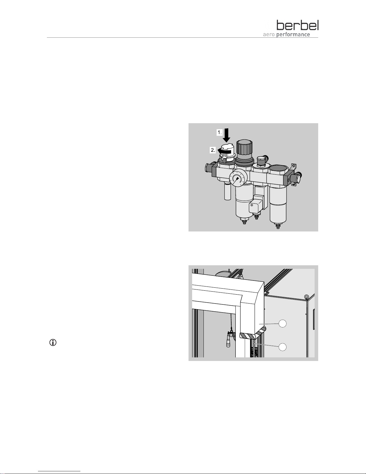
Structural features in illustrations
The illustrations contain portrayals in various grey
scales. Movements which are to be carried out are
made clear using movement or direction arrows. If
several action steps are portrayed in one
illustration, the sequence is made clear using
numbers (1., 2., ...):
If reference is made to elements in a legend or in
the body text, these are provided with an item
number (2):
2
1

3
Table of contents
Safety ..............................................................................................................................................................5
Proper use ..........................................................................................................................................................5
Ban on independent conversions and modifications ..........................................................................................5
Basic safety instructions .....................................................................................................................................5
Structural features of the information on dangers ..............................................................................................7
Structural features of notices regarding material or environmental damage......................................................7
Description.......................................................................................................................................................8
Possible operating modes ..................................................................................................................................8
Basic information on the device..........................................................................................................................9
View of the device from above .........................................................................................................................10
View of the device from below with flap closed ................................................................................................11
View of the device from below with flap open ..................................................................................................12
Air extraction mode........................................................................................................................................13
Outgoing air in the separate outgoing air duct .................................................................................................14
Optimising the outgoing air line ........................................................................................................................14
Preparing for installation ................................................................................................................................18
Personnel qualifications....................................................................................................................................18
Required aids....................................................................................................................................................18
Unpacking.........................................................................................................................................................19
Checking the scope of delivery.........................................................................................................................19
Removing parts for installation .........................................................................................................................21
Removing the lower tray (lower grease tray)....................................................................................................21
Removing the "Capillar Trap" ...........................................................................................................................22
Removing the brackets.....................................................................................................................................22
Creating the installation cut-out ........................................................................................................................22
Installing the device .......................................................................................................................................24
Maintaining safety distances ............................................................................................................................24
Installing the brackets.......................................................................................................................................25
Attaching the device .........................................................................................................................................25
Aligning the device horizontally ........................................................................................................................26
Securing the locking mechanism......................................................................................................................26
Adjusting the stop for the depth setting ............................................................................................................26
Connecting the connection contact for wall box and window switch (multi-function contact) ..........................27
Creating the outgoing air connection................................................................................................................30
Installing the removed parts .............................................................................................................................32
Connecting the current supply..........................................................................................................................33
Cleaning surfaces..........................................................................................................................................35

4
Dismantling the device...................................................................................................................................36
Disposal.........................................................................................................................................................37
Disposing of packaging.....................................................................................................................................37
deviceDisposal..................................................................................................................................................37
Technical data ...............................................................................................................................................38
Model plate .......................................................................................................................................................38
Built-in hood BEH 60 FL ...................................................................................................................................38
Built-in hood BEH 90 FL ...................................................................................................................................38
Contacting the manufacturer..........................................................................................................................39

Safety
5
Safety
Read through this chapter carefully before installing,
using or cleaning the device.
¾ Observe all information on dangers during all
activities on the device.
¾ Enclose these instructions if you pass the device
on.
Proper use
The device can be used to extract cooking vapours
during cooking.
The device is exclusively intended for this purpose
and must only be put to this use. The device must
only be used in the manner described in these
instructions.
Any other use or modification of the device is
regarded as improper and may lead to damage.
The manufacturer accepts no liability for damage
caused as a result of improper use, incorrect
installation or incorrect operation. The device is not
intended for commercial use. Use the device in
private kitchens only.
Ban on independent conversions and
modifications
• Do not undertake any independent conversions or
modifications on the device. Conversions or
modifications without the approval of berbel
Ablufttechnik GmbH are impermissible.
• Never bridge or bypass the protective facilities
available on the device.
Basic safety instructions
This section contains basic safety instructions for
handling the device. Additional safety instructions
which affect certain actions and procedures can be
found in the relevant chapters.
• Heed all of the safety instructions and information
on dangers in these instructions.
• Check the device and all parts for visible damage.
In the event of damage, contact your specialist
dealer or the berbel customer service. The device
must only be used in flawless condition.
• Always have repair and maintenance work carried
out by qualified, specialist personnel. Otherwise,
you endanger yourself and others.
• Install the device with the enclosed brackets
exclusively on load-bearing parts of buildings
(solid construction).
• In the case of other mountings, use
correspondingly suitable mounting techniques. If
in doubt, ask your specialist dealer. Otherwise,
you endanger yourself and others.
• Use the device in private kitchens only.

Safety
6
Avoiding dangers due to electric shock
• Have work on the voltage supply carried out by a
qualified, trained specialist electrician only.
At the very least, the specialist electrician must
have the following knowledge and skills:
− Basics of electrical engineering
− Knowledge of the country-specific regulations
and standards (in Germany e.g.
DIN 57100/VDE 0100, Part 701)
− Knowledge of the relevant safety regulations
− Knowledge of the relevant legal regulations for
gas installations (in Germany e.g. the technical
regulations for gas installations TRGI).
• Only use the device if it is connected and fused
according to the technical data.
• Do not kink or crush the mains cable.
• Do not operate the device with a damaged
electrical connection cable.
• Disconnect the device from the current supply in
the event of malfunctions.
• The mains plug must be freely accessible so that
the device can be easily and quickly disconnected
from the mains power supply in an emergency. If
the mains plug is inaccessible following
installation, an all-pole isolating device with a
contact opening of at least 3 mm must be
provided in the installation.
• If the device is brought into a warm environment
from a cold environment, moisture may form
inside the device. In this case, wait for
approximately two to three hours before starting
up the device.
• Avoid exposing the device to dripping or splashing
water. Never place objects filled with fluids, such
as e.g. vases, on the device.
• Keep the device dry.
• If fluid nevertheless enters the device:
− Immediately shut off the current supply by
removing the fuse.
− Make sure that the device's current supply
cannot be unintentionally reactivated. E.g.
designate a person to prevent the fuse from
being switched on.
− Allow the device to dry.
− Have the device checked and repaired by
trained, specialist personnel before using the
device again.
Avoiding risk of explosion
• Do not operate the device in an explosive
environment.
Avoiding fire hazard
• Make sure that the cooker top has cooled down
before covering it.
A soiled device may cause fire hazards.
• Keep the device in flawless condition and check it
regularly.
• Regularly remove any grease residues which are
present. Grease residues pose a fire hazard.
• Do not flambé beneath the device. Naked flames
may e.g. damage neighbouring cupboards.
• Only have repair work on the device carried out
by personnel trained for this purpose.
In recirculated air mode:
• A covered or sealed ventilation outlet may cause
fire hazards. Do not place any objects such as
e.g. cloths or plates on or in front of the device's
ventilation slits. In the case of recirculated air
devices, outflowing air must be able to escape
back into the kitchen through the ventilation slits
without impediments.
• No objects which may impede the air flow may be
installed above the device. Make sure that the
outflowing air is able to flow into the kitchen
without impediments.
Safety
7
The device may only be installed above a fireplace
for solid fuels (e.g. coal-fired stove) if:
• the fireplace has a sealed cover which cannot be
removed. Otherwise, e.g. there is an increased
fire hazard due to flying sparks.
• the legal and country-specific regulations are
adhered to.
Avoiding risks of injury
• In order to prevent the risk of falling, use a stable
stepladder for all work on the device, such as e.g.
replacing the filter, installing and cleaning the
device.
• In order to prevent risks of injury due to falling
parts, use suitable mounting material.
• In order to prevent cuts due to broken glass, use
suitable protective gloves.
Avoiding the risk of suffocation
If the device and an open fireplace which is
dependent on the room air are operated
simultaneously, gases or waste gases may be
drawn into the room.
• Make sure that all of the permits required for
operation in your country are available (e.g. those
of the master chimney sweep).
• Make sure that all standards and guidelines for
operating the device in your country are observed.
• Ensure an adequate fresh air supply in the
dwelling.
• Do not allow children to play with film or other
parts of the packaging.
• Store film or other parts of the packaging in a
location which is inaccessible to children.
Preventing the risk of collapse
• The necessary wall passage must be created by a
specialist company. Wall passages influence the
building's statics. Improperly created wall
passages may lead to the collapse of the building.
Avoiding environmental damage
• Dispose of the device and its accessories
according to the legal regulations.
Structural features of the information on
dangers
The following categories of information on dangers
are contained in these instructions:
DANGER
Notices containing the word DANGER
warn of a hazardous situation which
leads to death or severe injuries.
WARNING
Notices containing the word
WARNING warn of a hazardous
situation which may lead to death or
severe injuries.
CAUTION
Notices containing the word CAUTION
warn of a situation which may lead to
slight or moderate injuries.
Structural features of notices regarding
material or environmental damage
ATTENTION
These notices warn of a situation
which leads to material or
environmental damage.
Description
8
Description
The following illustrations show functions or
dimensions. The devices which are used are
shown as symbols. The illustrations are
intended to provide assistance to the
installation engineer. The device forms which
are shown may deviate from the actual
appearance of your devices.
The device can be used in various operating
modes:
• Recirculated air mode
• Air extraction mode
• Hybrid mode
Installation of the device differs depending on the
operating mode which is desired. The different
installation of the individual operating modes is
described in the following sections.
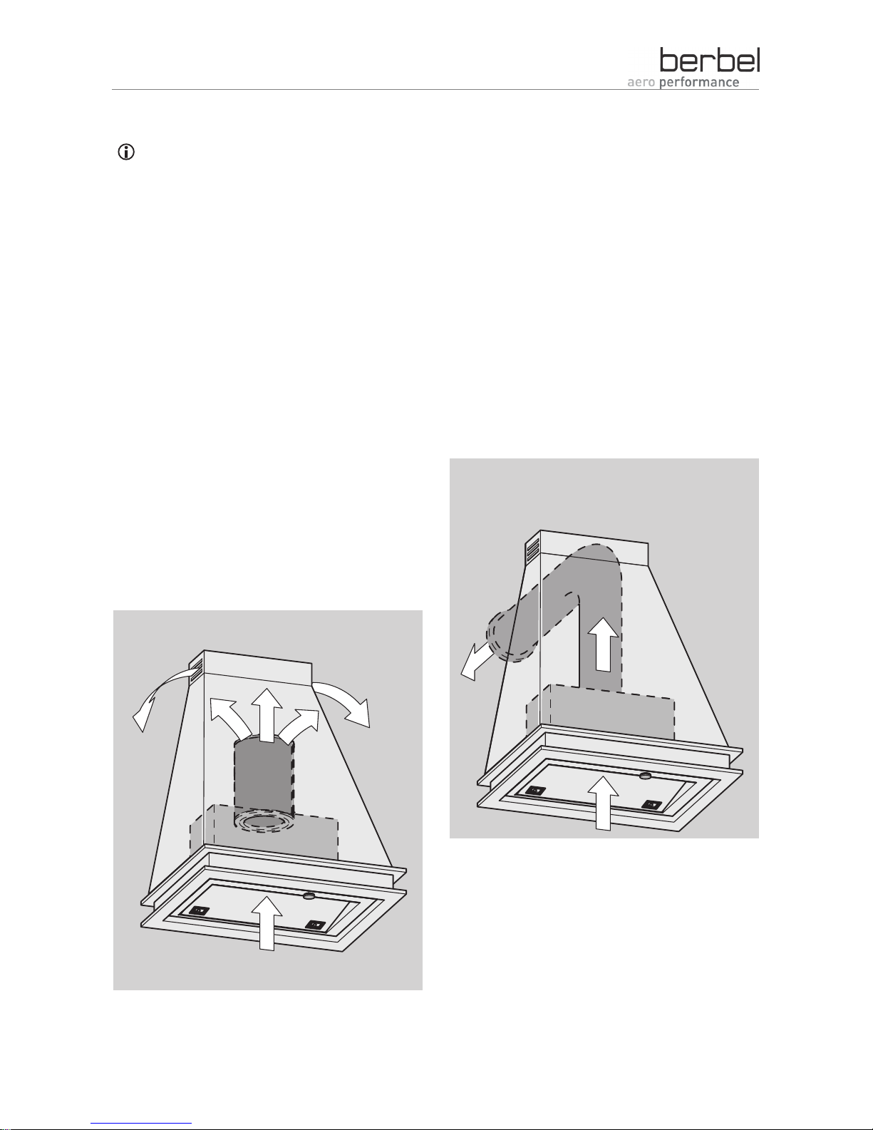
Possible operating modes
Installation for recirculated air mode
The device intakes room air, filters the room air and
returns the odour-free, cleaned room air into the
room.
During installation, a recirculating air filter BUF is
placed onto the device's fan outlet.
¾ Make sure that the cross-section of the ventilation
slits in the upper elements is greater than
200 cm
2
.
¾ Make sure that the filter filling can be replaced at
a later point in time.
The filter filling must be replaced at regular
intervals.
Installation for air extraction mode
The device intakes room air, filters the room air and
conducts the room air outside.
Description
9
Installation for hybrid mode
The device intakes room air, filters the room air, and
conducts part of the room air outside and returns
part of the room air, cleaned and odour-free, into
the room.
During installation, a hybrid filter BHF is placed onto
the device's fan outlet. The outgoing air line is
connected to the hybrid filter.
¾ Make sure that the cross-section of the ventilation
slits in the upper elements is greater than
200 cm
2
.
¾ Make sure that the filter filling can be replaced at
a later point in time.
The filter filling must be replaced at regular
intervals.
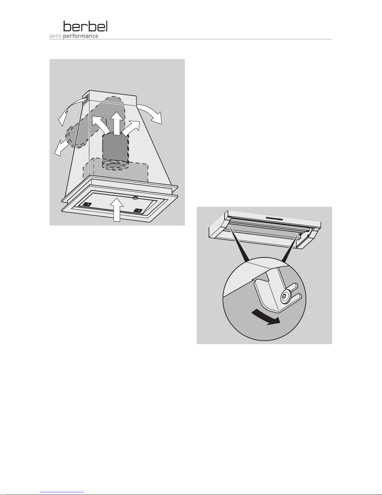
Basic information on the device
The device is designed for installation in cupboards.
The front panel can be pulled out to obtain a larger
intake area. The rear end position of the front panel
can be adjusted.
The device's functions are controlled using the
control in the centre of the front panel.
The two brackets which are contained in the scope
of delivery are screwed laterally to the inner walls of
the cupboard.
Once the levers in the device have been pretensioned, the device is hooked in from below. The
tensioned levers engage automatically when the
end position has been reached.
Description
10
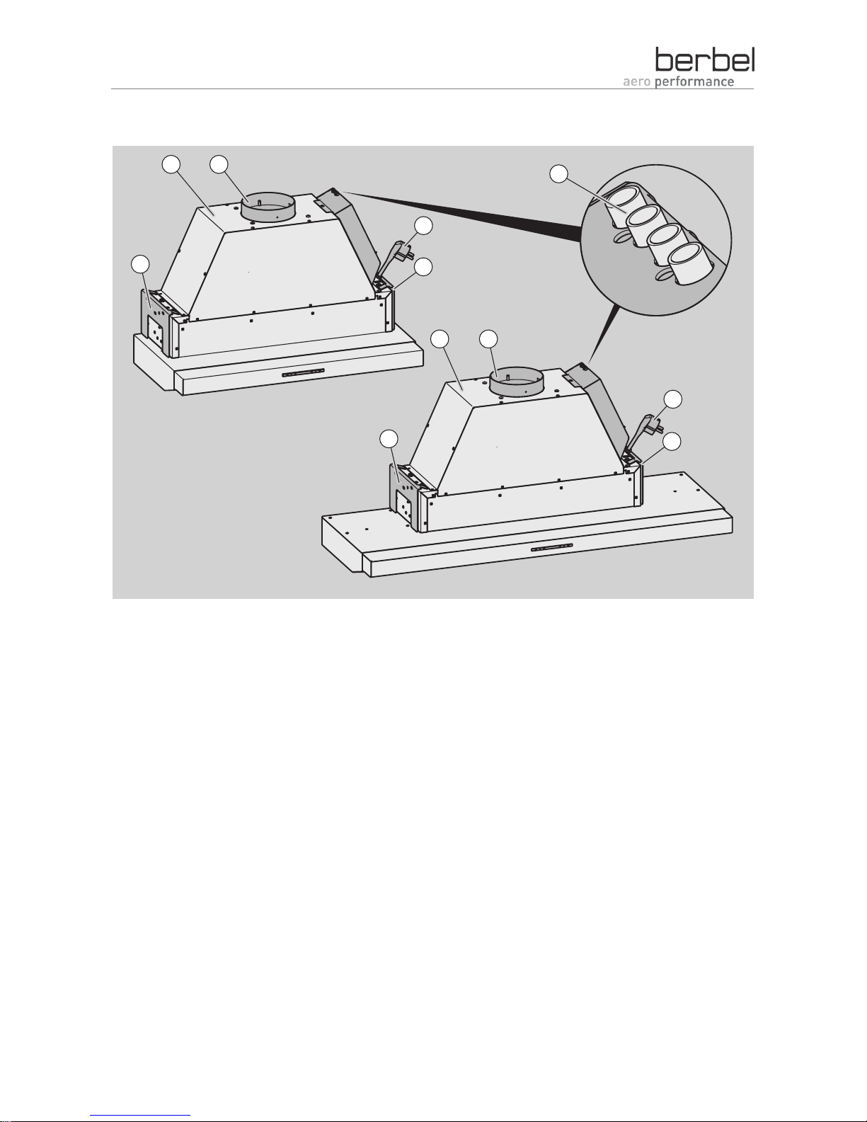
View of the device from above
31
2
4
5
6
7
3
6
7
4
Built-in hood BEH 60 FL Contacts for window switches (multi-function
contact) and wall box BMK
Built-in hood BEH 90 FL Right bracket
Fan outlet with guide aid for filter and outgoing
air line
Left bracket
Mains plug
Description
11
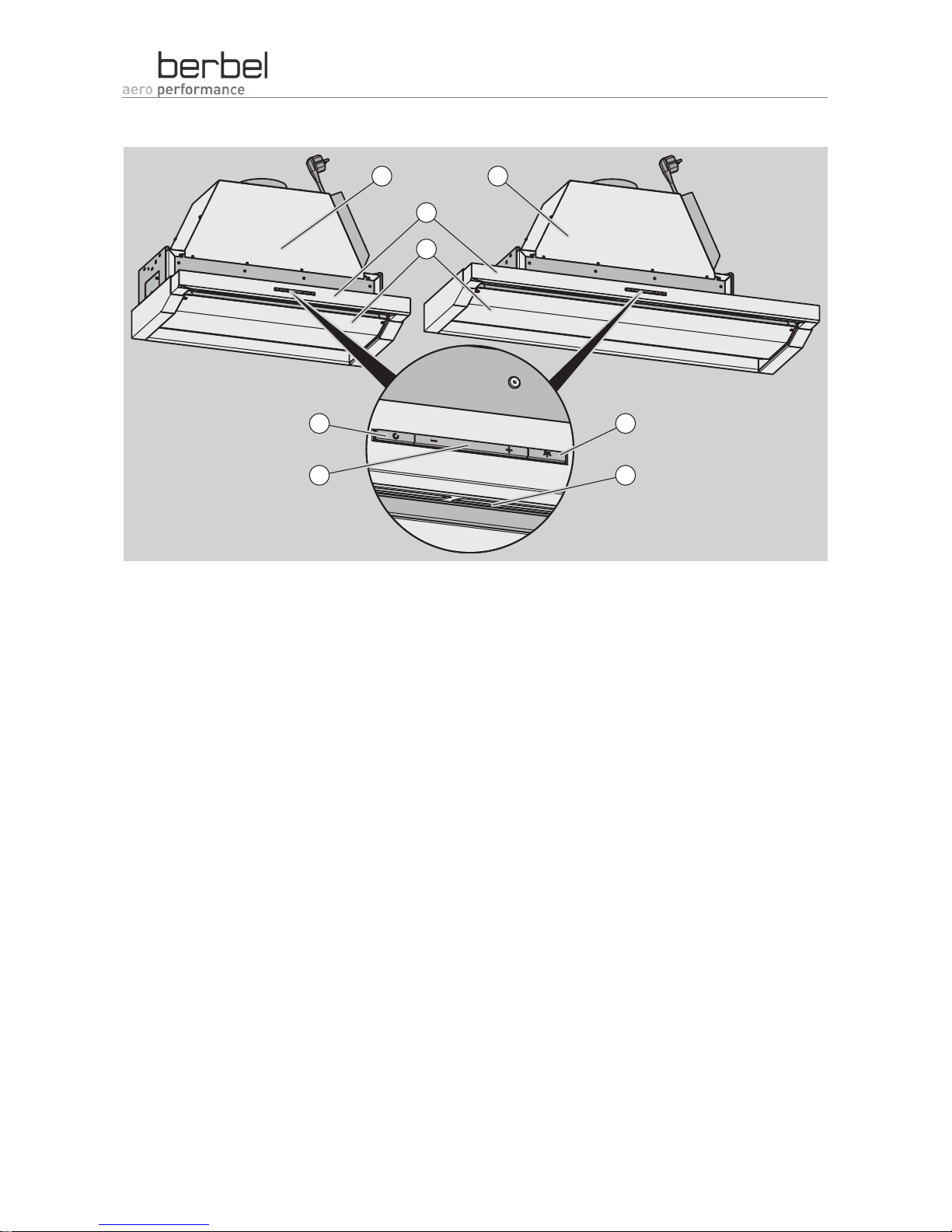
View of the device from below with flap closed
7
8
4
6
5
1
3
2
Built-in hood BEH 60 FL Lighting ON/OFF button
Built-in hood BEH 90 FL Lighting
Extension Change output level button
Flap with lower grease tray Switch on run-on button
Description
12
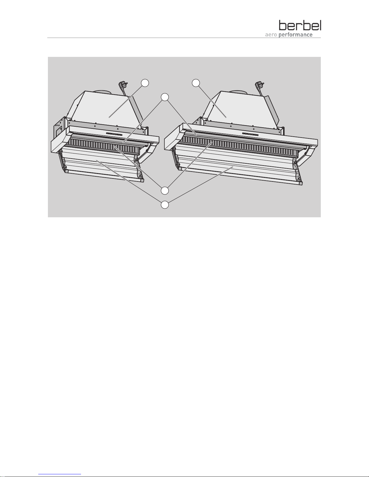
View of the device from below with flap open
3
4
5
1 2
Built-in hood BEH 60 FL "Capillar Trap"
Built-in hood BEH 90 FL Flap with lower grease tray
Upper grease tray
 Loading...