

Page 1
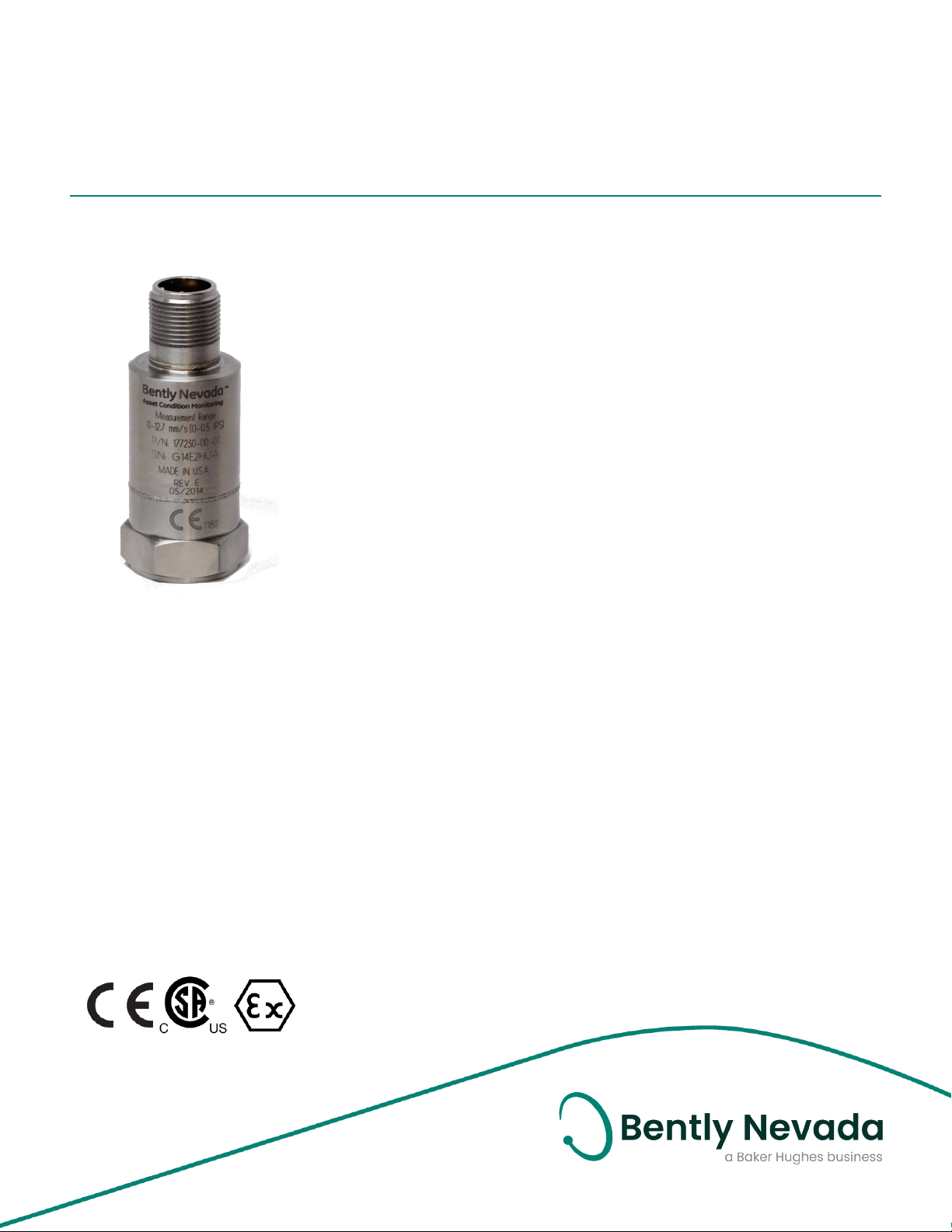
177230 Seismic Transmitter
Datasheet
Bently Nevada Machinery Condition Monitoring
Description
The 177230 Seismic Transmitter is a simple, loop-powered
device that can be quickly and easily installed. It can be
integrated into your programmable logic controller (PLC)or
controls system linked to a plant asset condition monitoring
solution. Its simple design reduces training, maintenance,
and service costs. The transducer helps you better manage
downtime, optimize maintenance planning, and avoid
unforeseen catastrophic failures of machinery assets.
The 177230 Seismic Transmitter incorporates robust CM
design for reliability and implements an industry-standard 4
to 20 mA loop-powered transmitter.
Easily Installed and Integrated
l Interfaces with PLCs and control systems (including
DCS and SCADA)
l Requires only a short learning curve for operations and
maintenance –through a familiar interface similar to
that for connecting other PLC or control system inputs
l Requires no field configuration or adjustments
l Needs few additional parts for a complete system
l Includes technical support for customers on how to
monitor their equipment
l Includes self-test
l Incorporates protected interface
l Supports a variety of interface cables
177232 Rev. O
Data Quality
l Provides accurate and repeatable data
l Uses simple data format
l Provides raw vibration signal for verification and
analysis
Page 2

177230 Seismic Transmitter
Datasheet 177232 Rev. O
EHS Compliant
l Implements safe and ergonomic design
l Supports access to hazardous areas
2/10
Page 3
177230 Seismic Transmitter
Datasheet 177232 Rev. O
Referenced
Specifications
to Pin B
Electrical
Sensitivity –
Main Loop
(Signal
One)
Output
Format, Pin
A
Referenced
to Pin B
Excitation
Voltage
This product is for use with PLCs, DCS
and SCADA systems that have internal
power supplies which are typically
current limited in the range of 30 mA to
35 mA.
Settling
Time
Connector
Wiring
Convention
Frequency
Response
Sensitivity –
Dynamic
Signal
(Signal
Two)
Output
Format, Pin
C
n 0.0 to 12.7 mm/s (0 to 0.5 in/s)
n 0.0 to 25.4 mm/s (0 to 1.0 in/s)
n 0.0 to 50.8 mm/s (0 to 2.0 in/s)
± 10% FS, broadband rms (root
mean square)
[4 ± 0.3 mA equals 0.0 mm/s
and 20 ± 2 mA equals 25.4
mm/s]
4 to 20 mA current loop Velocity
vibration
12 to 30 Vdc (current limited to
40 mA)
Less than 15 seconds within 2%
of final value
n Pin A: 4-20 mA Positive Loop
n Pin B: 4-20 mA Negative Loop
and common for Dynamic
Signal
n Pin C:Dynamic Signal in
voltage, unbuffered
10 Hz to 1 kHz (600 cpm to 60
kcpm) ± 10%
10.2 mV/m/s2 (100 mV/g) ± 20%
Voltage, Acceleration vibration
The Dynamic Signal Negative (Pin B)
requires isolation from any grounding.
If this terminal is grounded, the 4-20
mA loop will short, resulting in no
output.
Frequency
Response
Linearity ±1%
Output Bias
Referenced
to Pin B
Full Scale
Range
Velocity
Range (see
Option AA
and BB)
Mounted
Resonant
Frequency
Transverse
Sensitivity
Sensing
Element
Type
2.5 Hz to 10 kHz (150 cpm to 600
kcpm) ± 10%
2.5 V ± 0.1 V
147 m/s2 ( 15 g’s) peak
n 0 – 12.7 mm/s (0 – 0.5 in/s)
n 0 – 25.4 mm/s (0 – 1.0 in/s)
n 0 – 50.8 mm/s (0 – 2.0 in/s)
Greater than 12 kHz
Less than 5% of sensitivity
Ceramic / Shear
Environmental Limits
Operating
Temperature
Range
Electrical
Isolation
Isolation
Breakdown
Voltage
Shock
Survivability
-40 °C to +85 °C
(-40 °F to +185 °F)
Greater than 108 ohms
600 Vrms with less than 1 mA
leakage current
9.810 m/s2 (1.000 g peak),
maximum drop test
3/10
Page 4
177230 Seismic Transmitter
Datasheet 177232 Rev. O
This part typically mounts directly to
the machine via a stud. Customers
can use this device with a magnetic
base, but must take care not to “snap”
the unit onto the machine. This
snapping action can create a very
large spike signal that can damage
the electronics. Rolling the magneticbase onto the machine greatly
reduces the spike signal so that the
unit should not have any issues.
Sensor Seal Hermetically sealed
Relative
Humidity of
Transmitter
Magnetic
Field
Sensitivity
To 100% non-submerged
Less than 20 μm/s/gauss (790
μin/s/gauss) peak
Less than 14.7 mm/s2/gauss
(150 μg/gauss) peak
[based on 50 gauss, 50 - 60 Hz]
Physical
Weight 131 g (4.62 oz), typical
Diameter 25.4 mm (1.00 in)
Height 66.0 mm (2.60 in)
Case
Material
Connector 3-pin MIL-C-5015, 316L stainless
Mounting
Hole
Mounting
Threads
These stud adapters are provided with
each device. For additional adapters,
see Ordering Information on page7. Or
contact Benty Nevada Tech Support.
316L stainless steel
steel
1/4-28 UNF
M6 X 1 SI
M8 x 1.25 SI
¼-28 UNF
Mounting
Torque
Connector Wiring Convention
Pin A 4-20 mA Loop Power (Positive
Pin B 4-20 mA Loop Return (Negative/
Pin C Dynamic Signal (Unbuffered,
4 to 7 N-m (35.4 to 62.0 in-lbf)
with reference to Pin B)
return for Dynamic Signal)
referenced to Pin B)
4/10
Page 5
177230 Seismic Transmitter
Datasheet 177232 Rev. O
Class III, Div 1
Compliance and Certifications
FCC
This device complies with part 15 of the
FCC Rules. Operation is subject to the
following two conditions:
l This device may not cause harmful
interference.
l This device must accept any
interference received, including
interference that may cause
undesired operation.
EMC
EMC Directive 2014/30/EU
RoHS
RoHS Directive 2011/65/EU
Maritime
330400and 330425 only
ABS 2009 Steel Vessels Rules
1-1-4/7.7,4-8-3/1.11.1,4-9-7/13
Hazardous Area Approvals
For the detailed listing of country and
product specific approvals, refer to the
Approvals Quick Reference Guide
(108M1756) available from Bently.com.
CSA/NRTL/C
Install per drawing 177234
T4 @ Ta ≤ 80°C
200150,
200155,
200157
200350 (Approval Option 1)
Intrinsically
Safe
Intrinsically
Safe and
NonIncendive
Ex ia IIC T4
Class I, Div 1
Groups A,B,C,D
T4 @ -40°C ≤ Ta ≤ 80°C
Per DWG 167535
Ex nL IIC T4
Class I, Div 2
Groups A,B,C,D
T4 @ -40°C ≤ Ta ≤ 80°C
Per DWG 167535
Ex ia IIC T4
Class I, Division 1, Groups A, B, C
and D
AEx ia IIC T4
Class I, Division 1, Groups A, B, C
and D
T4 @ -54 °C ≤ Ta ≤ +121 °C
(-65.2 °F ≤ Ta ≤ 249.8 °F )
Per drawing 175825
Ex nL IIC T4
Class I, Division 2, Groups A, B, C
and D
AEx nA T4
Class I, Division 2, Groups A, B, C
and D
T4 @ -54 °C ≤ Ta ≤ +121 °C (-65.2 °F
≤ Ta ≤ +249.8 °F ) per drawing
17582
177230 Ex nL IIC T4:
AEx nA IIC T4:
Class I, Div 2, Groups A, B, C, D.
Ex ia IIC T4:
AEx ia IIC T4:
Class I, Div 1, Groups A, B, C, D;
Class II, Div 1, Groups E, F, G;
5/10
Page 6
177230 Seismic Transmitter
Datasheet 177232 Rev. O
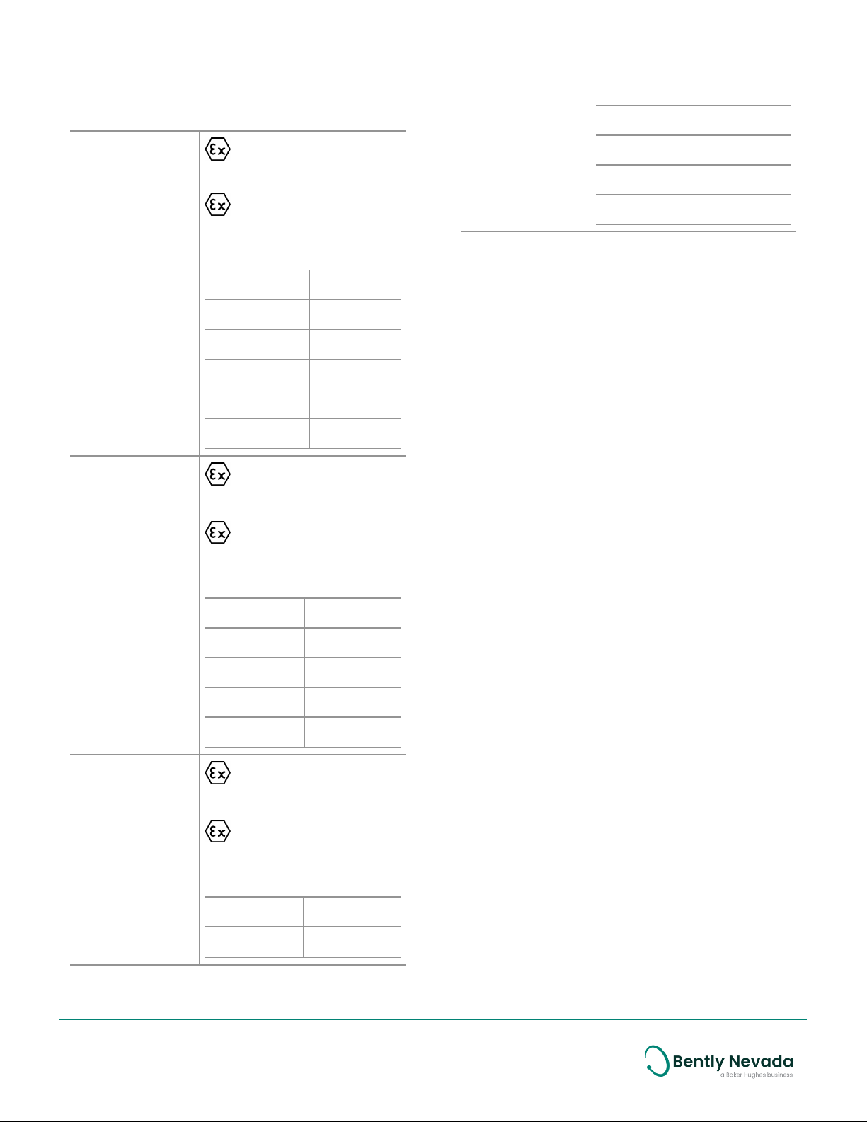
ATEX/IECEx
Ii= 200mA Ii= 200mA
177230
II 1 G
Ex ia IIC T4 Ga
II 3 G
Ex na IIC T4 Gc
Pi= 1W Pi= 1W
Ci=16.2 nF
Li= 0
Entity
Parameters
200150, 200155,
200157
Entity
Parameters
T4@ Ta = -40°C to 80°C
Zone 0/1 Zone 2
Ui= 28V Ui= 28V
Ii= 120mA Ii= 120mA
Pi= 1W Pi= 1W
Ci=0
Li=121.06µh
II 1 G
Ex ia IIC T4 Ga
II 3 G
Ex na IIC T4 Gc
T4@ Ta = -40°C to 80°C
Zone 0/1 Zone 2
Ui= 27V Ui= 27V
Hazardous Area Conditions of Safe Use
ATEX/IECEx
Zone 0/1:
Equipment must be connected to equipment,
which meets the above listed entity
parameters.
The cables type A or B (in compliance with EN
60079-25) must respect the cable parameters
listed with the entity parameters.
Zone 2 :
The supply electrical parameters shall not
exceed the values mentioned in the tables
above.
200350
Entity
Parameters
Ii= 150mA Ii= 150mA
Ci=16.2 nF
Li= 0
II 1 G
Ex ia IIC T4 Ga
II 3 G
Ex na IIC T4 Gc
T4@ Ta = -54°C to +121°C
Zone 0/1 Zone 2
Ui= 28V Ui= 28V
6/10
Page 7
177230 Seismic Transmitter
Datasheet 177232 Rev. O
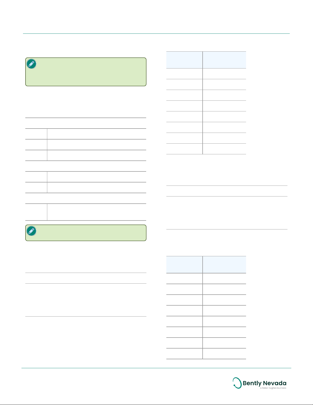
These standard lengths are available. You can
order custom lengths at additional cost.
Ordering Information
For the detailed listing of country and
product specific approvals, refer to the
Approvals Quick Reference Guide
(108M1756) available from Bently.com.
Seismic Transmitter
Feet Meters
(approx.)
10 3.1
12 3.6
15 4.5
177230-AA-BB-CC
A: Measurement Range
00 0 – 12.7 mm/s (0 – 0.5 in/s)
01 0 – 25.4 mm/s (0 – 1.0 in/s)
02 0 – 50.8 mm/s (0 – 2.0 in/s)
B: Frequency
01
02 3 Hz to 1 kHz (180 to 60 kcps) pk
C: Approvals
05
10 Hz to 1 kHz (600 to 60 kcps) rms
Multiple Approvals (CSA/NRTL/C,
ATEX/IECEx)
Only standard or common AA-BB-CC
configurations are available.
Interconnect Cable without Armor
17 5.0
20 6.0
25 7.6
30 9.0
99 30.0
Interconnect Cable with Armor
16710-AA
A: Length in feet
Order in increments of 1 foot (0.3 m)
Minimum length: 3 feet (0.91 m)
Maximum length: 99 feet (30.2m)
Example: 25 = 25 feet
These standard lengths are available. You can
order custom lengths at additional cost.
16925-AA
A: Length in feet
Order in increments of 1 foot (0.3 m)
Minimum length: 3 feet (0.91 m)
Maximum length: 99 feet (30.2m)
Example: 25 = 25 feet
Feet Meters
(approx.)
08 2.4
10 3.1
12 3.6
15 4.5
17 5.0
20 6.0
30 9.0
99 30.0
7/10
Page 8
177230 Seismic Transmitter
Datasheet 177232 Rev. O
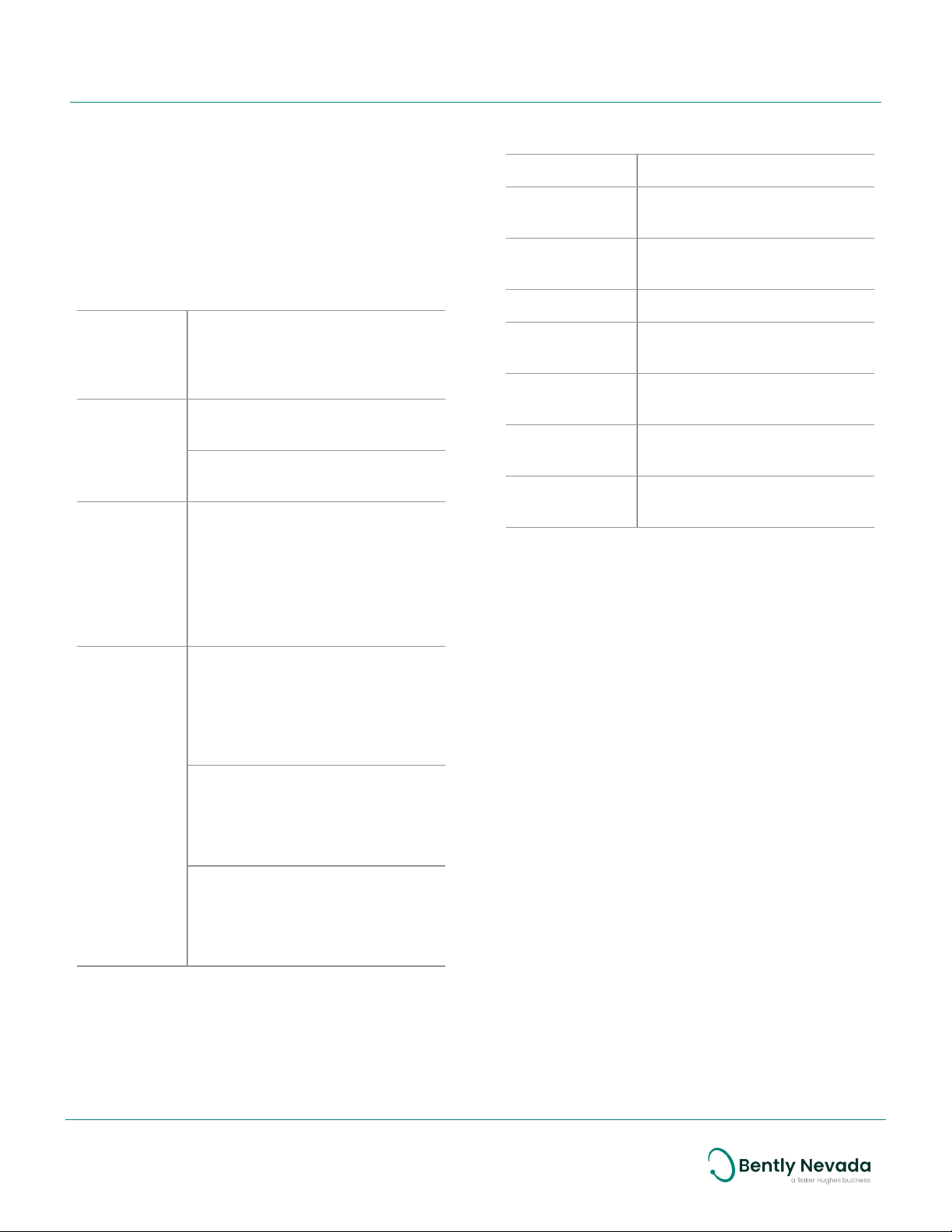
Studs and Adapters
Ordering Accessories
You can order these accessories from the
vendors named. Contact the vendor with the
part number and ask for their part that fits your
application.
3-Pin Connector (MIL-C-5015)
Base Cannon (ITT industries)
Shell
Wire (3-wire
with shield)
ittcannon.com
P/N: CA3106R-10SL-3S F97 or
P/N: MS3106R-10SL-3S
Sunbank Co.
sunbankcorp.com
Glenair, Inc.
glenair.com
Three-conductor 18 to 22 AWG
cables with a 0.01” minimum
outer jacket and inner wire
insulation, and 80% minimum
coverage shield. Insulation
rating should be 600 V
minimum.
Part No. Description
89139-01 M-M ¼-28 UNF to ⅜ -24 UNF
standard stud
128038-01 M-M ¼-28 UNF to ⅜ -24 hex
plate stud (1-⅜ ” X 0.25”)
146396-01 F-M ¼-18 NPT to ¼-28 adapter
146394-01 F-M ¼-28 UNF to ¼-18 NPT
adapter
37439-01 F-M ¼-28 UNF to ¼-28 UNF
mounting base
164373 M-M ¼-28 UNF to ¼-28 UNF
standard stud with brass tip
135826-01 M-M ¼-28 UNF to M10 X 1.0
standard stud
Mil-W16878/4
(TypeE)
Sonic/Thermax
thermaxcdt.com
18 AWG - P/N: 18-TE-1930 (3) SXE
22 AWG - P/N: 22-TE-1934 (3)
SXE
Standard Wire and Cable Co.
std-wire.com
18 AWG - P/N: 1100-88T
22 AWG - P/N: 1100-66T
Belden
belden.com
18 AWG - P/N: 83336
22 AWG -P/N: 83334
8/10
Page 9
177230 Seismic Transmitter
Datasheet 177232 Rev. O
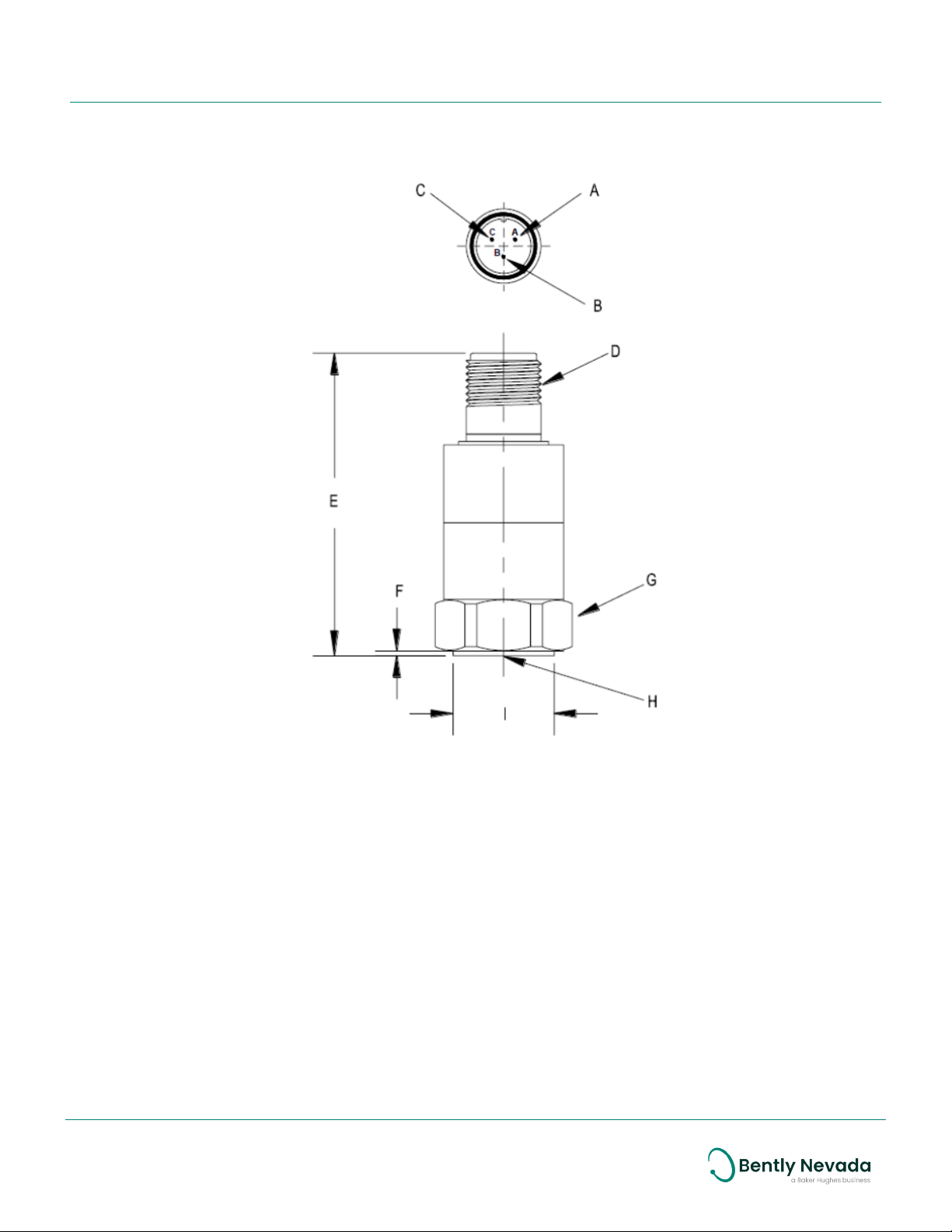
Graphs and Figures
Dimensions shown in mm (inches) except as noted.
A. Positive loop (4-20 mA)
B. Negative loop (4-20 mA) and common for dynamic signal
C. Dynamic signal
D. 3-pin MIL-C-5015, 5/8-24 UNEF-2A
E. 66.0 mm (2.60 in)
F. 1.27 mm (0.050 in)
G. 25.4 mm (1.00 in)
H. 1/4-28 UNF-2B (English)
I. 25.1 mm (0.990 in)
Figure 1: Transducer Mechanical Outline and Dimensions
9/10
Page 10

177230 Seismic Transmitter
Datasheet 177232 Rev. O
Copyright 2020 Baker Hughes Company. All rights reserved.
Bently Nevada and Orbit Logo are registered trademarks of Bently Nevada, a Baker Hughes Business, in the United
States and other countries. The Baker Hughes logo is a trademark of Baker Hughes Company. All other product and
company names are trademarks of their respective holders. Use of the trademarks does not imply any affiliation
with or endorsement by the respective holders.
Baker Hughes provides this information on an “as is” basis for general information purposes. Baker Hughes does not
make any representation as to the accuracy or completeness of the information and makes no warranties of any
kind, specific, implied or oral, to the fullest extent permissible by law, including those of merchantability and fitness
for a particular purpose or use. Baker Hughes hereby disclaims any and all liability for any direct, indirect,
consequential or special damages, claims for lost profits, or third party claims arising from the use of the
information, whether a claim is asserted in contract, tort, or otherwise. Baker Hughes reserves the right to make
changes in specifications and features shown herein, or discontinue the product described at any time without
notice or obligation. Contact your Baker Hughes representative for the most current information.
The information contained in this document is the property of BakerHughes and its affiliates; and is subject to
change without prior notice. It is being supplied as a service to our customers and may not be altered or its content
repackaged without the express written consent of Baker Hughes. This product or associated products may be
covered by one or more patents. See Bently.com/legal.
1631 Bently Parkway South, Minden, Nevada USA 89423
Phone: 1.775.782.3611 or 1.800.227.5514 (US only)
Bently.com
10/10
 Loading...