

Page 1
SOFTWARE MANUAL
®
Page 2

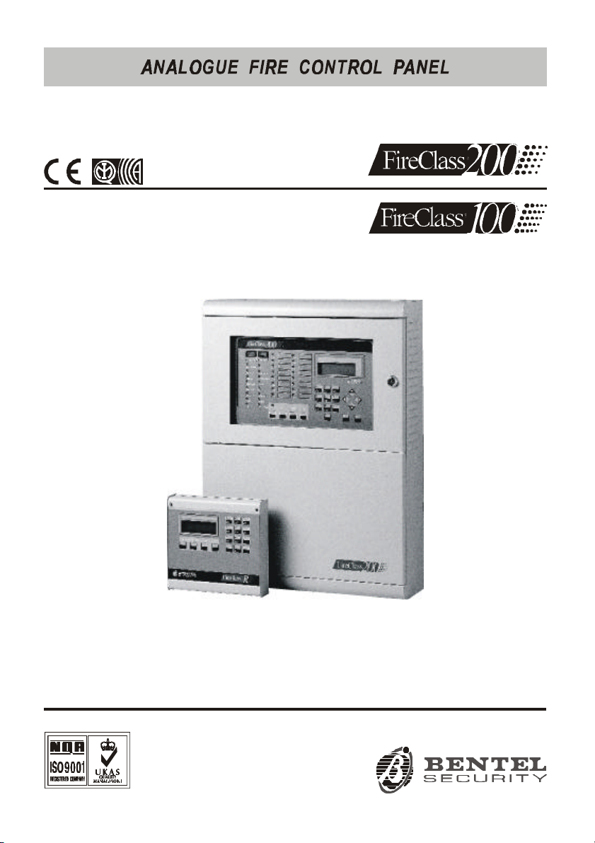
Use this manual with the following Analogue Fire control panels:
FC200 - 2 Loop Master panel with 4 A Linear power supply
FC200/S - 2 Loop Master panel with 2.5 A Switching power supply
FC200/SL - 2 Loop Slave panel without power unit
FC100 - 1 Loop Control panel with 2.5 A Switching power supply
The name FireClass has been used in this manual to describe features
common to all the above listed panels.
BENTEL SECURITY reserves the right to change the technical features of
these products without prior notice.
Via Gabbiano, 22 - Z.I. S.Scolastica
64013 CORROPOLI (TE) - ITALY
Software Manual: FireClass Analogue Fire Control panel
ISTRUZIONI SOFTWARE INGLESE FC100-200/UK ISTSOFFIREC/UK
Page 3
TABLE OF CONTENTS
INSTALLATION 5
Introduction . . . . . . . . . . . . . . . . . . . . . . . . 5
Installing the Fire Software suite . . . . . . . . . . . . 5
Select Language . . . . . . . . . . . . . . . . . . . . . . 5
Fire Software 7
Communicating with Fireclass control panels . . . . . 7
Main window . . . . . . . . . . . . . . . . . . . . . . . . 9
File . . . . . . . . . . . . . . . . . . . . . . . . . . . . 9
Programming . . . . . . . . . . . . . . . . . . . . . . 13
Parameter Settings . . . . . . . . . . . . . . . . . . . 13
Control . . . . . . . . . . . . . . . . . . . . . . . . . 15
Modem . . . . . . . . . . . . . . . . . . . . . . . . . 18
Help . . . . . . . . . . . . . . . . . . . . . . . . . . . 19
Programming Peripheral Devices . . . . . . . . . . . 19
Password . . . . . . . . . . . . . . . . . . . . . . . . 20
Telephone . . . . . . . . . . . . . . . . . . . . . . . 20
Options . . . . . . . . . . . . . . . . . . . . . . . . . 22
System . . . . . . . . . . . . . . . . . . . . . . . . . 23
Factory . . . . . . . . . . . . . . . . . . . . . . . . . 24
Log window . . . . . . . . . . . . . . . . . . . . . . . 25
Control panel Log management . . . . . . . . . . . . 26
Customer Account Log . . . . . . . . . . . . . . . . . 26
Print and Close . . . . . . . . . . . . . . . . . . . . . 27
Translat 28
File Menu . . . . . . . . . . . . . . . . . . . . . . . . . 29
Search Menu . . . . . . . . . . . . . . . . . . . . . . . 30
Find Text . . . . . . . . . . . . . . . . . . . . . . . . 30
Create language . . . . . . . . . . . . . . . . . . . . . 31
Copy language . . . . . . . . . . . . . . . . . . . . . . 31
Modify Language . . . . . . . . . . . . . . . . . . . . 32
3
Page 4

dbManager 35
File Menu . . . . . . . . . . . . . . . . . . . . . . . . . 35
Export data . . . . . . . . . . . . . . . . . . . . . . . 36
Copying Customer accounts . . . . . . . . . . . . . . 38
GMap 39
Graphic map management window . . . . . . . . . . 41
Management menu . . . . . . . . . . . . . . . . . . . 42
Settings Menu . . . . . . . . . . . . . . . . . . . . . . 42
Map settings . . . . . . . . . . . . . . . . . . . . . . 44
New backgrounds . . . . . . . . . . . . . . . . . . . . 45
New Symbols . . . . . . . . . . . . . . . . . . . . . . 45
Create Map . . . . . . . . . . . . . . . . . . . . . . . . 45
Notes . . . . . . . . . . . . . . . . . . . . . . . . . . . 47
4 Analogue Fire Control Panels FireClass
Page 5
Introduction
The Bentel Fire suite contains the Management software applications for
the FC100/200, J400 and J524 control panels and the PCJ400 Interface.
Select FC100/200 control panel, to access the following applications:
Fire Software: Control panel Programming and Management application.
Translat: Language application (customizes system terminology).
DBManager: Data export application.
GMap: Supervisory application (with graphic layouts).
Installing the Fire Software suite
Work carefully through the following steps to install the Bentel Fire Suite
applications.
1. Run the Setup.exe application contained in the CdRom.
INSTALLATION
2. Select a folder for the Bentel Fire Suite applications.
3. Check the installation settings then click on Next. If changes are neces-
sary - click on Back.
Select Language
You can select the language of the Bentel Fire Suite applications (Fire
Software, GMap and dbManager) from the Languages provided, or use
the Translat application to customize the application terminology.
To Select the application language:
1. Run the Fire Software application.
2. Select Settings from the Main window.
INSTALLATION 5
Page 6
2. Select System Settings from the drop-down menu to open the Parameter
settings then click-on Miscellaneous.
3. Select a language from the Language list.
4. Click-on OK.
To initialise the selected language ---- close then re-open the application.
+
The source language of the Translat application is English.
+
2
2
4
3
1
3
5
6
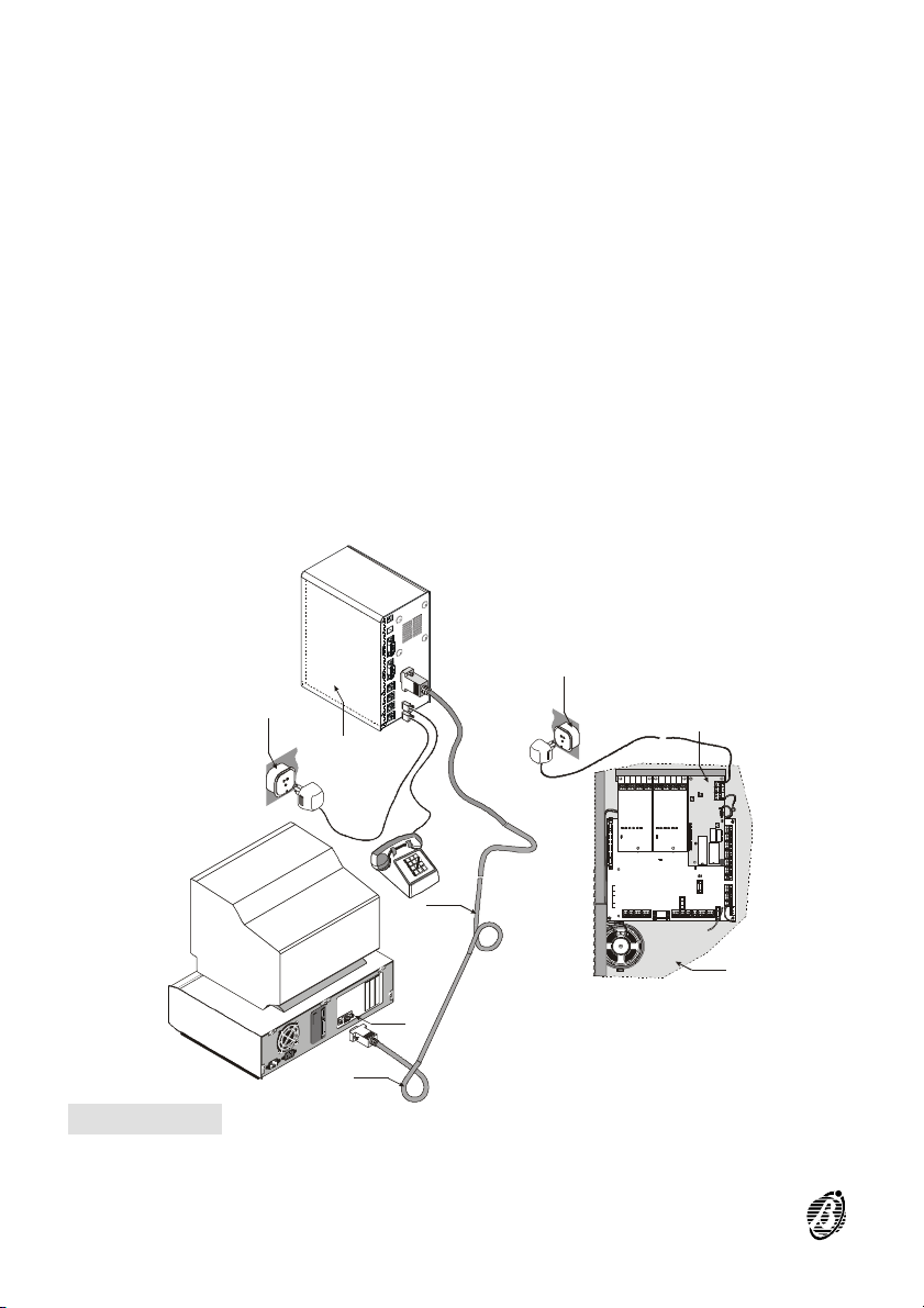
Figure 1 Remote link between the Fireclass control panel and PC.1) PC serial port;
2) Telephone network; 3) CVSER/9F9F wires; 4) BMOD or BMOD-RX modem; 5) Telecom Module FC200/COM; 6) FIRECLASS 200.
6 Analogue Fire Control Panels FireClass
Page 7
The Fire Software application will allow you to program, manage, supervise and communicate with FireClass control panels.
Communicating with Fireclass control panels
If you are using the Supervisory, Management, Downloading and Log
Management functions, the control panel must be connected to your PC (in
local/remote communication).
It is not necessary for the control panel to be connected to your PC during
the parameter programming phase.
If you are using the Fire system supervisory function of the GMap applica-
+
tion, the control panel must be connected to your PC.
Local/Remote Communications:
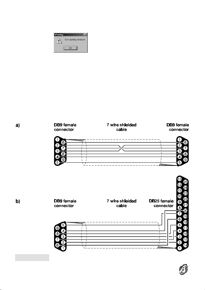
1. Using a CVSER/9F9F cable (accessory item) or similar cable (see figure
1a), connect the control panel serial port (refer to "PARTS IDENTIFICATION" in the "INSTALLATION MANUAL") to a serial port on your PC.
2. Select the PC serial port from the Local Communication sheet (Setting
parameters window).
Fire Software
For 25 pin serial ports ---- use an ADSER/9M25F adapter (accessory item)
or make a cable as per figure 2b.
Remote communications with Fireclass control panels require a
BMOD/BMOD-RX modem (see figure 1).
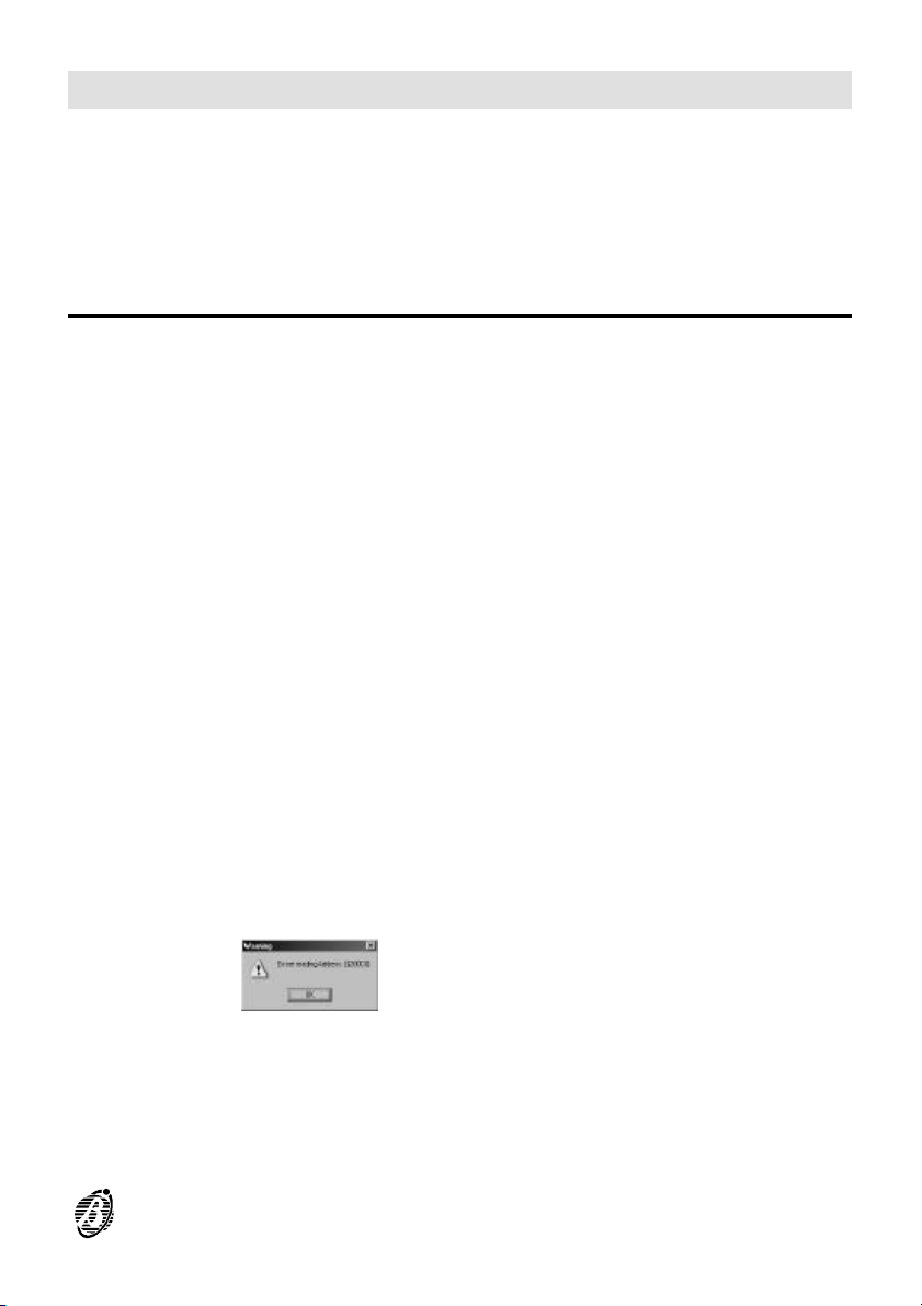
If the control panel is not connected to your PC when you start the com-
+
munication, the following warning will be shown.
Fire Software 7
Page 8
If the serial port for the local communication is invalid, the following warn-
+
ing will be shown.
Select OK to continue.
Figure 2 PC to Control panel cable link
8 Analogue Fire Control Panels FireClass
Page 9
Main window
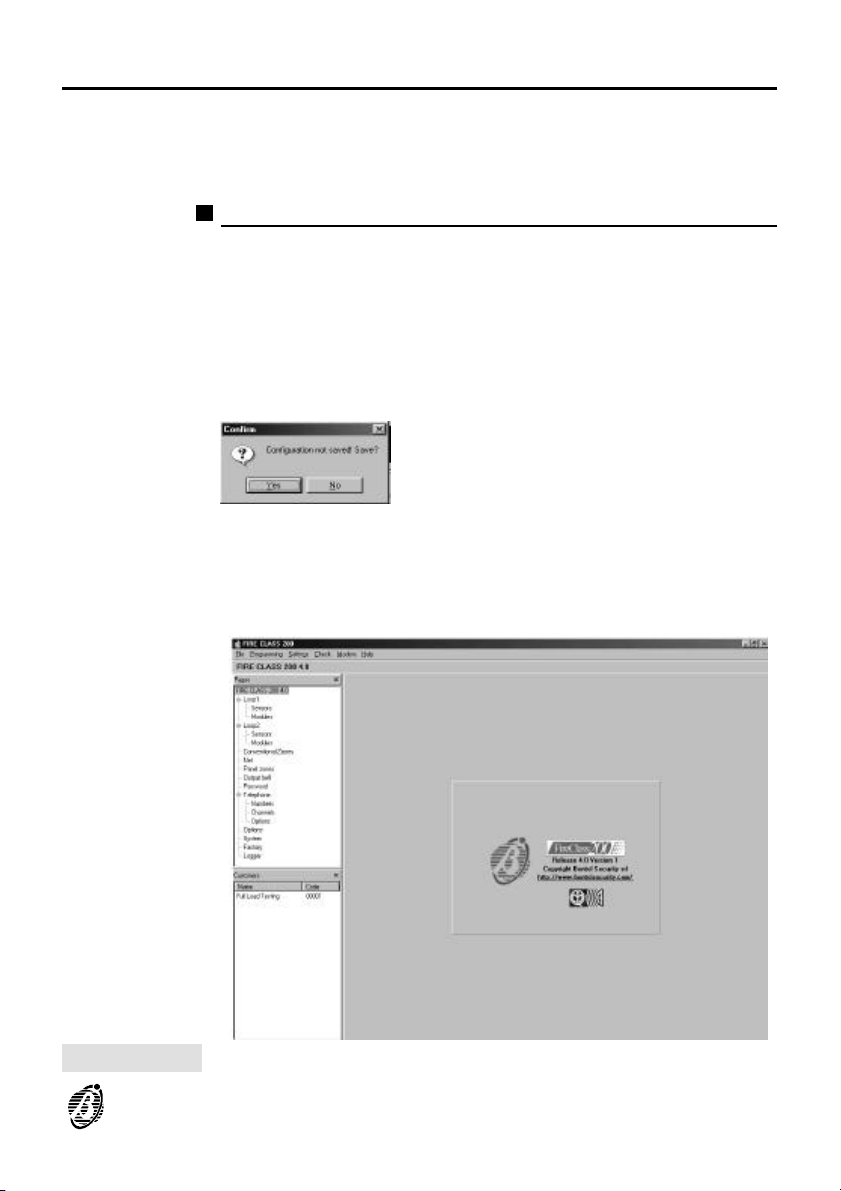
The Fire Software application opens on the Main window (see fig. 3).
The following section describes the File, Programming, Settings, Check,
Modem and Help menus.
File
The File options (New Customer, Save configuration, Print, Exit) will allow
you to manage customer account data. The details and system configuration of each customer account will be saved to the hard disk database.
New Customer This option will allow you to assign and/or reset default parameters.
If, on selecting the New Customer option, the application finds unsaved
parameters, the following message will be shown:
If you click-on Yes, the Customer account window will open (refer to
"Save" section).
If you click-on No, the application will abandon any changes.
Figure 3 Main window
Fire Software 9
Page 10
configuration
Save
To retrieve customer data from the database ---- right-click on the customer
account concerned (Main window Fig.3).
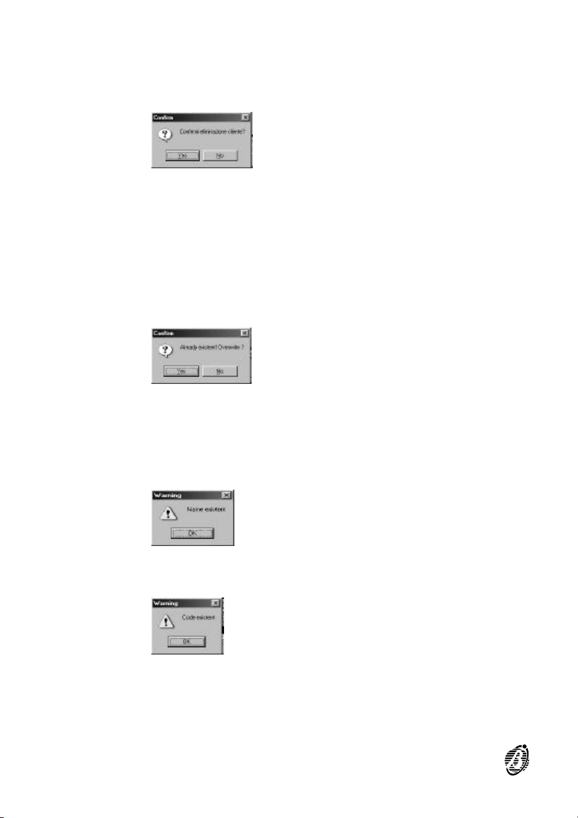
To delete the retrieved customer data from the database click-on Delete,
the application will show the following message:
If you click-on Yes, the respective customer data will be deleted from the
hard disk database.
This option will allow you to save the customer account data to the hard
disk database.
Customers are identified by their Name and Code, therefore:
Ø If you try to save Customer data using a duplicated Name or Code, the ap-
plication will show the following warning:
If you click-on Yes, all new values will overwrite previous settings.
This application is not case sensitive.
+
Ø If you try to save customer account data using a duplicated Name and a
new Code, the application will show the following warning:
Ø If you try to save customer account data using a new Name and a dupli-
cated Code, the application will show the following warning:
10 Analogue Fire Control Panels FireClass
Page 11
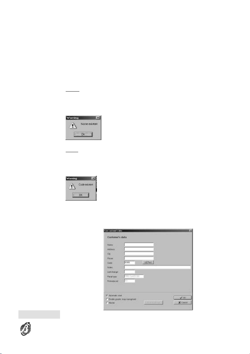
If you make changes to an existing customer account, you must type in the
+
respective Name and Code.
If you select Save, the application will open the Customer account win-
dow (see fig. 4).
The Address, City, Telephone, Notes, Panel Type and Firmware version
fields are for Installer records only.
The following data is fundamental to the programming process:
Name You must assign a different name to each customer account. The
name will identify the customer in all parts of the application. If you try to
save customer account data using a duplicated Name and new Code, the
application will show the following warning:
Code You must assign a different Code (up to 5 digits) to each customer
account.
If you try to save customer account data using a new Name and a duplicated Code, the application will show the following warning:
Figure 4 Customer account window
Fire Software 11
Page 12
Last Save This parameter indicates the date of the last Save operation for
the customer account concerned.
The Customer account window provides the following options.
Automatic start If you enable this option, the application will load the re-
spective customer account automatically each time the Fire Software application opens.
Enable Graphic map management This option will allow you to associate
the customer account with the GMap application.
Master Graphic map management This option will allow you to associate
systems using Master and Slave panels (maximum 7 Slaves) with the
GMap application. The Set Slave button will activate automatically.
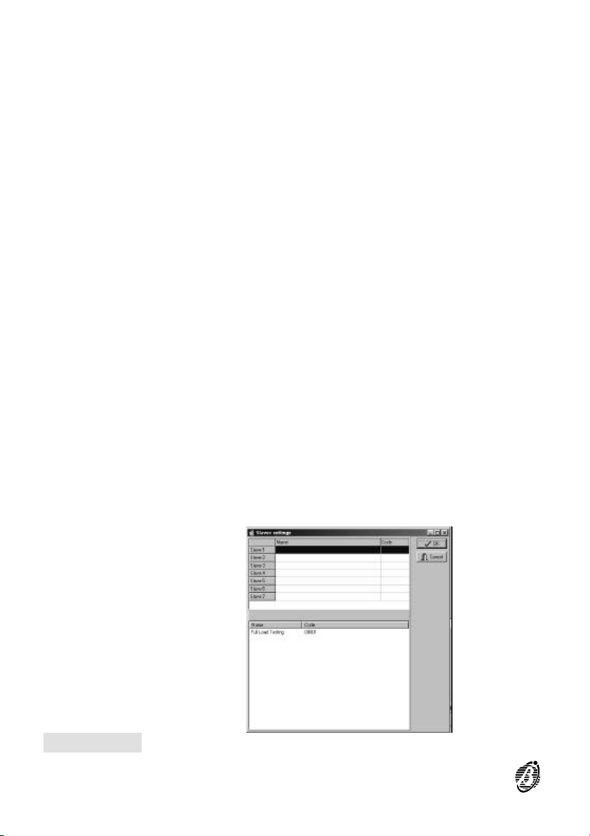
Slaves settings This option (see Fig. 5) will allow you to configure the
Slave panel network. If you click on Slave (bottom centre), the Slave panel
will be moved automatically to the top section of the window.
NOTE: You must assign a different Name and Code to each Slave panel.
Print This option will allow you to printout the currents settings.
To print the contents of the device windows (detectors, modules, zones,
+
bell outputs, etc.), right-click on the respective device and select Print.
Exit Select Exit to close the application.
Figure 5 Slave Control panels
12 Analogue Fire Control Panels FireClass
Page 13
Programming
This section describes the uploading/downloading process.
Upload Select Upload from the Programming menu to upload all the parameters
Download Select Download from the Programming menu to download the parame-
Layout This option will allow you to change the view of the Main window (e.g
Parameter
Settings
(via serial lonk or telephone line) of the connected control panel. Select
Upload on a window or sheet to upload the parameters of the respective
window or sheet.
ters (via serial or telephone line) to the connected control panel. Select
Download on a window or sheet to download the respective parameters to
the control panel.
Parameter Settings
Read this section carefully to get an overall view of the Layout, Parameter
Settings, Panel Code and Panel Type.
hide the Tree-view window, Customer account list, etc.).
This option will allow you to program the parameters of Local and Remote
communications and select the language.
Local Communication ---- This window will allow you to select the com -
puter serial port for the Fireclass control panel link up.
Ø Serial Port ---- This option will allow you to select the computer serial port
for the Fireclass control panel link up.
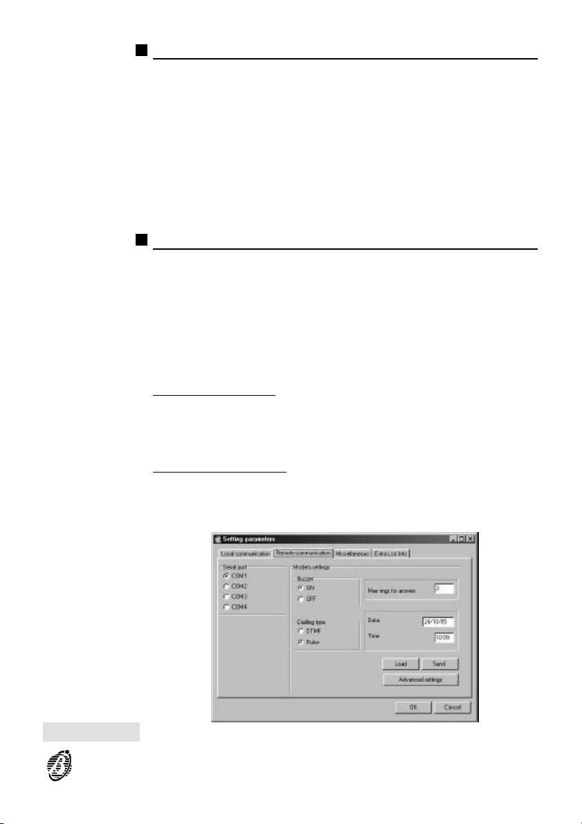
Remote Communication ---- This window will allow you to select the com-
puter serial port for the BMOD or BMOD-RX modem link up, and set up the
modem.
Figure 6 Setting parameters window
Fire Software 13
Page 14
Ø Serial port ---- This option will allow you to select the computer serial port
for the BMOD or BMOD-RX modem link up.
Modem settings:
Ø Buzzer ---- Enable/Disable
Ø Dialling Type ---- Pulse Tone or DTMF
Ø Maximum rings type ---- Maximum number of rings before the Telecom
module answers the call.
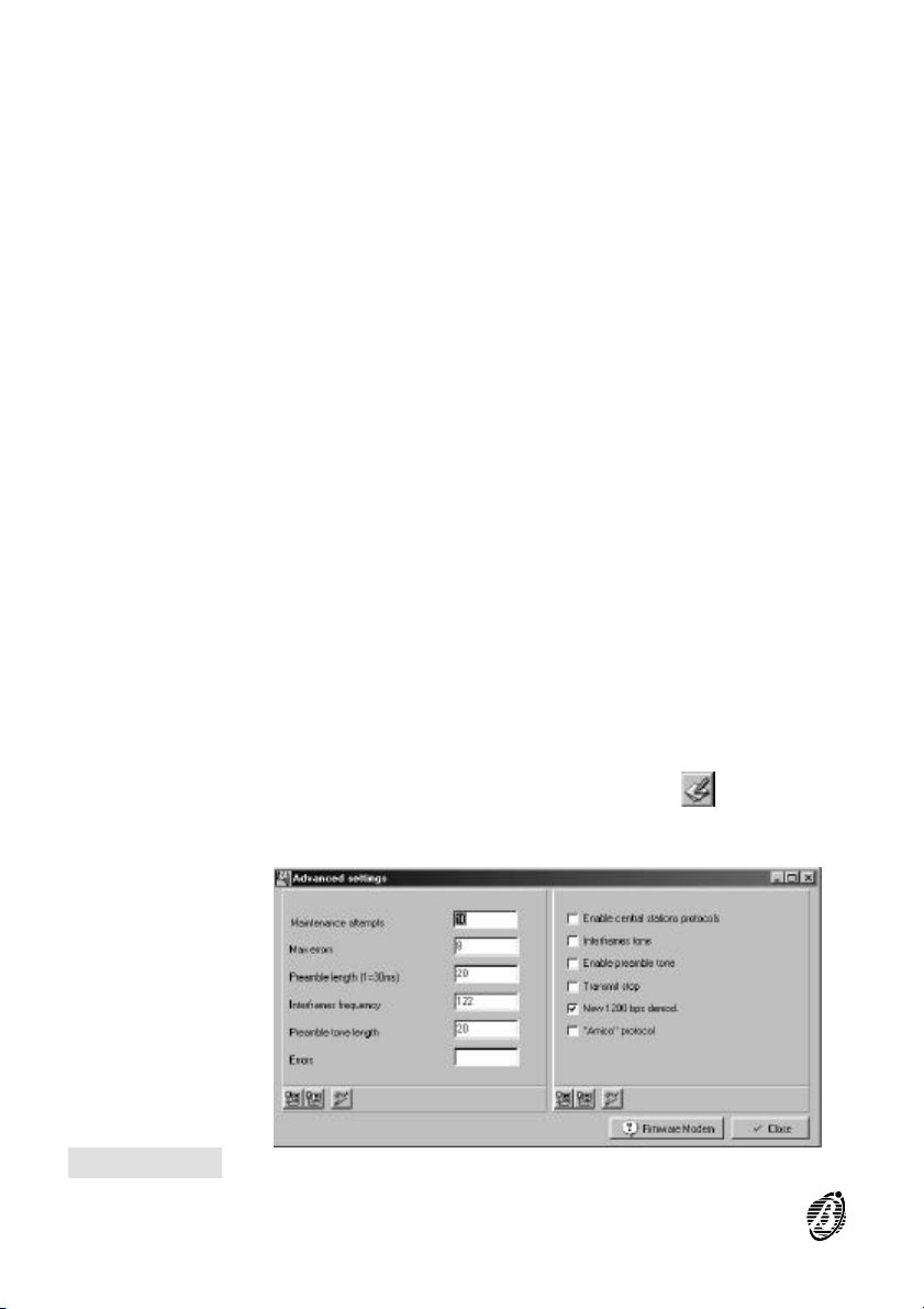
Ø Advanced settings Telephone communications data window (see fig.7).
The parameters in this window should not be changed without first contacting your Service centre.
Ø Miscellaneous ---- This window will allow you to set up the following pa-
rameters.
Ø Max. errors ---- This parameter is reserved for factory use and cannot be
changed.
Ø Language ---- This option will allow you to select the language of the Fire
Software Suite applications (Fire Software, dbManager and Gmap). You
must close then reopen the application in order to activate the selected
language.
You can select the Fire Software Suite language from the Language list or
+
customize the system terminology using the Translat application. The
source language of the Translat application is English.
Pause ---- This parameter is reserved for factory use and cannot be
changed.
Extra LCD Info This option can be used with Non-European languages.
If you select the "Use table conversion" option, the button will allow
you to open the "frmTableConv" window.
Figure 7 Advanced Settings window
14 Analogue Fire Control Panels FireClass
Page 15
Panel Code Type in the Installer Code (00000 at default) or User Code (11111 at de-
fault).
The Installer Code will allow you to operate freely on the system.
User Codes will allow you to read the system parameters and enable/disable the system peripheral devices.
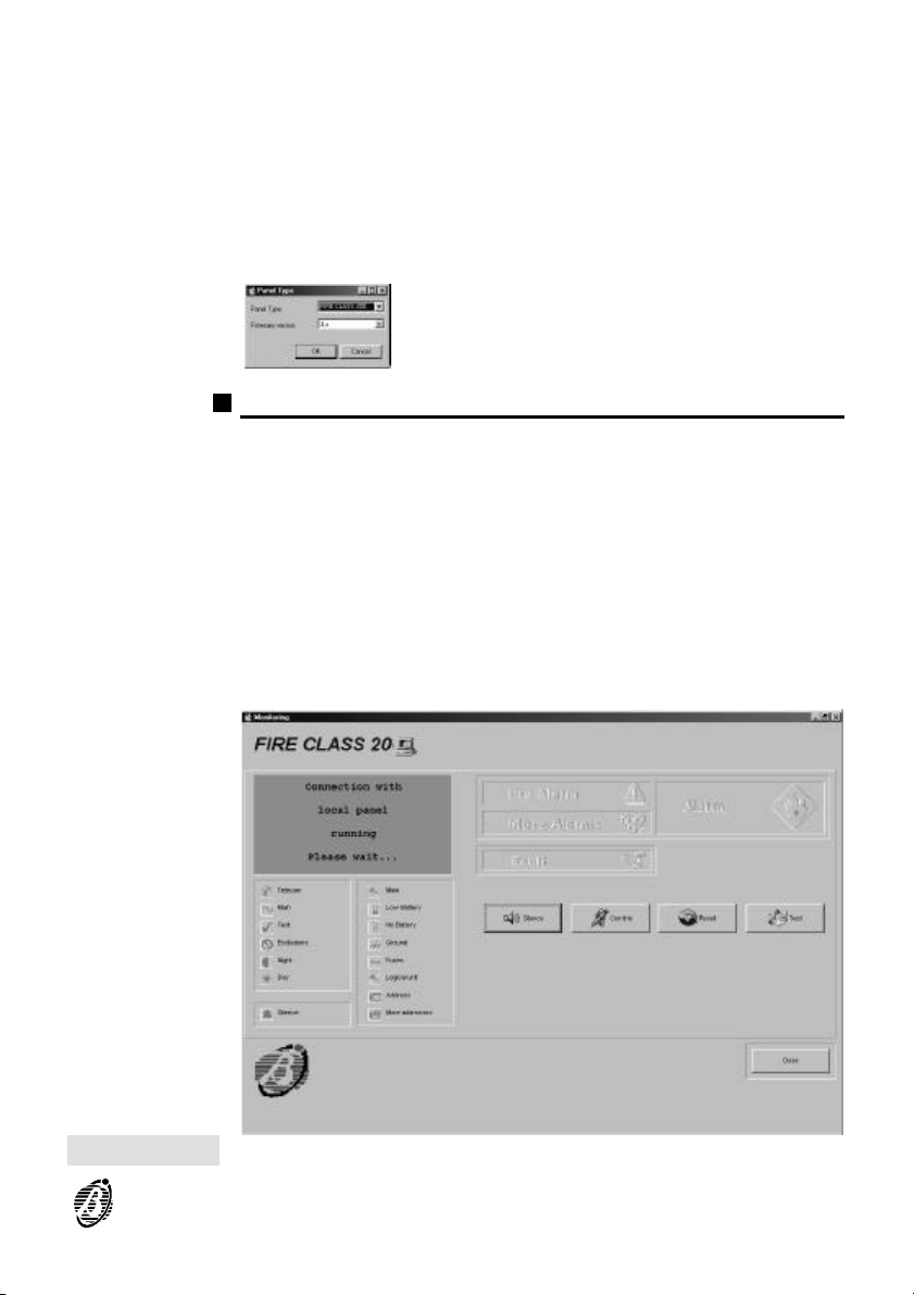
Panel Type This option will open a window showing the control panel model and re-
Enrol This option will allow you to configure the system before first start up, or af-
Monitoring The Monitoring window provides the virtual LEDs, buttons and display of
spective firmware version.
Control
The Control menu provides the Enrol, Monitoring and Management options.
ter changes to the configuration.
the connected FireClass control panel (refer to "PARTS IDENTIFICATION"
in the "INSTALLATION MANUAL" for details).
The GMAP application can be used ONLY when the Monitoring window
+
of the FireSoftware application is open.
Figure 8 Monitoring window
Fire Software 15
Page 16
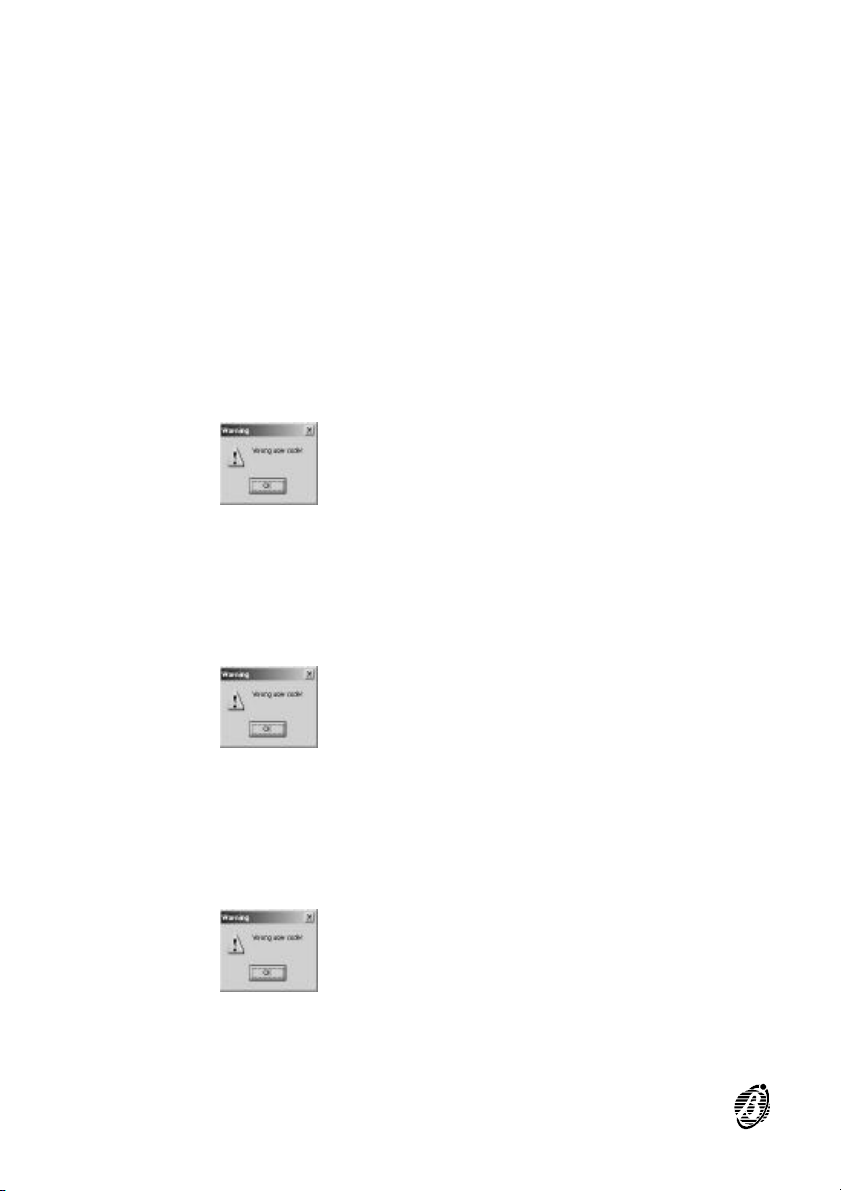
If you link a FireClass control panel to your PC you can:
Ø view the real-time status of the control panel concerned (indicated by the
virtual LEDs and display);
Ø use the Silence, Confirm, Reset and Test buttons, as follows.
The following section describes the Silence, Confirm, Reset and Test
buttons on the Monitoring window.
The Silence button silences/unsilences the audible and visual signalling
devices.
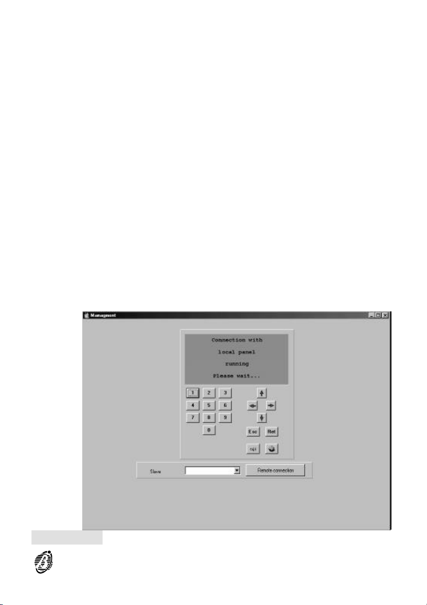
1.Click on the virtual Silence button.
If the code is valid, the status of the audible and visual signalling devices
will toggle (silenced to unsilenced and vice versa), otherwise, the application will show the following message:
The Confirm button will allow you to confirm a Software Zone alarms.
1.: Click on the Confirm button.
If the code is valid, the Software Zone alarm will be confirmed, otherwise,
the application will show the following message:
The Reset button will allow you to restore the system to standby.
1.: Click on the virtual Reset button.
If the code is valid, the system will restore the system to standby, other-
wise, the application will show the following message:
The Test button will allow you to test the system LEDs and control panel
buzzer:
16 Analogue Fire Control Panels FireClass
Page 17
1. Click on the virtual Test button.
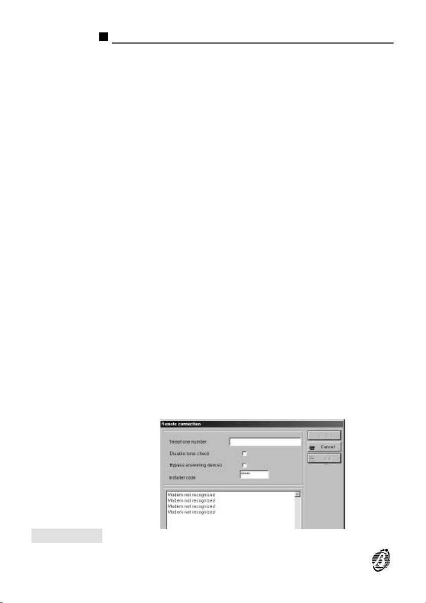
Management The Management window (fig.9) is a virtual control panel. It provides the
LEDs, buttons and display of the connected FireClass system (refer to
"PARTS IDENTIFICATION" in the "INSTALLATION MANUAL" for details).
If your PC is linked to a FireClass control panel you can:
Ø work on the system, using the virtual keypad and buttons.
Ø view the warnings and messages shown on the of the connected control
panel.
Communication
Remote
If the connected Control panel is a Master panel, you can also view and
manage its Slave panels, as follows.
1. Select the Slave panel from the Slave menu;
2. Click on the Remote Connection button.
Figure 9 Management window
Fire Software 17
Page 18
Modem
The B-Mod or B-Mod-RX modem will allow you to communicate with Fireclass
Control panels from a remote location. Access to this function requires entry of
the Installer PIN code and User authorization (i.e. the user must enable the
Teleservice function). For details regarding the Teleservice function, refer to
Telecom Module under Modifying in the "Installation Manual".
1. Using the serial cable, connect the Modem to one of the PC serial ports.
2. From the Main menu of the software application:
Settings > System Settings > Remote Communication > Serial Ports then
---- set up the serial port parameters (refer to Parameter Settings see also
Settings window Fig. 6);
---- click-on OK.
The Modem menu provides the Remote Communication and On hook options.
Communication
Remote
On hook Click on On hook from the Modem menu to end the communication.
3. Select Remote Communication to open the respective window (see Figure 10).
4. Program the respective parameters, as follows:
Telephone number ---- type in the Control panel telephone number;
Disable Tone check ---- if this option is enabled, the modem WILL NOT
CHECK the line for the dialling tone before dialling;
Bypass answering devices ---- if this option is enabled, the control panel will override any other line-sharing answering devices (fax machine, answerphone, etc.).
NOTE: All other line-sharing answering devices must be set to answer incoming calls after 2 or more rings.
Installer Code ---- type in the Installer Code.
With the exception of the Tone check option, the Remote Communica-
tion window initialises with preset parameters (programmed in other parts
of the application). Any changes made to the parameters in the Remote
Communication window will not affect the respective parameters in other
parts of the application.
5. Click on Dial to start the communication ---- the communication status
will be shown at the bottom of the window. At this point, you can download/upload to/from the connected control panel.
Successful communications will be confirmed by the following message:
Fireclass ACK01.00 CONNECTION
6. Click on OK to close the Remote Communication window.
Figure 10 Remote Communication window
18 Analogue Fire Control Panels FireClass
Page 19
Help
Click on this option to open the Software Manual PDF file.
Programming Peripheral Devices
The Main menu (see Figure 3) will allow you to:
---- View the real-time status of the connected control panel (Check >);
---- Save the configuration to the database (File > Save Configuration);
The Tree-view window (far left on the Main window) will allow you to:
---- View and set the FireClass control panel parameters;
---- Enable/Disable the devices of connected control panels: Detectors,
Modules, Conventional Zones, Network (Repeater panels, Slave panels), Control panel Zones (Software Zones) and Bell Outputs, as follows.
Click on:
Upload ---- to upload selected parameters;
Download ---- to download selected parameters;
Upload ALL ---- to upload ALL the parameters of the control panel concerned;
Download ALL ---- to download ALL the parameters of the control panel
concerned.
Right-clicking on the various labels in the tree-view window will open a
+
drop down menu with the following options: Select, Upload, Download
and Print. Uploading/Downloading operations take several minutes.
The Network option will allow you to select the Alarm status template
(Standard or Extended) for the Repeater panels, as follows:
---- click on Network to access the respective programming sheet;
---- select ALL then click on Download to configure the Repeater network.
A window will open which will allow you to select the Extended template
option (refer to "Repeater Display Template" in the "User Guide").
Figure 11 Password window
Fire Software 19
Page 20
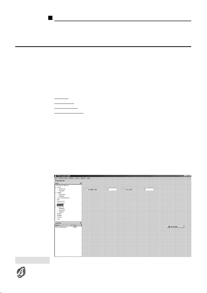
Password
Use the Password sheet (figure11) to program the Installer and customer
account Codes.
Telephone
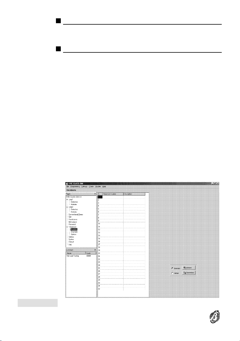
Use the Telephone sheet to program the:
Ø Telephone numbers, Channels, Options
Numbers The Telecom module will call the telephone numbers programmed in this
Channels Use the Channels sheet to program the Telecom module operating mode:
sheet, when the assigned events occur (refer to Tel.Num in the Telephone paragraph ---- INSTALLATION MANUAL).
On the bottom right of the sheet the Select, Download and Upload buttons determine the type of downloading.
Dialler and / or Digital Communicator (refer to Dial. and Commun. in the
Telephone paragraph ---- INSTALLATION MANUAL). Message management (record / play messages) is not possible when programming via software. Message management (record / play messages) is possible only
when programming from the keypad.
This sheet will allow you to program the test channel (see figure 14):
---- type in the automatic Teleservice call data (refer to Commun. in the
Telephone paragraph ---- INSTALLATION MANUAL).
Figure 12 Telephone window
20 Analogue Fire Control Panels FireClass
Page 21
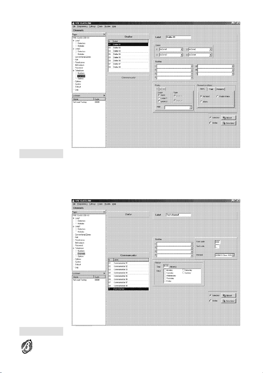
Figure 13 Telephone channels window
Options This sheet will allow you to program the Telephone options (refer to Op-
Figura 14 Test channel window
tions in the Telephone paragraph (INSTALLATION MANUAL).
Fire Software 21
Page 22
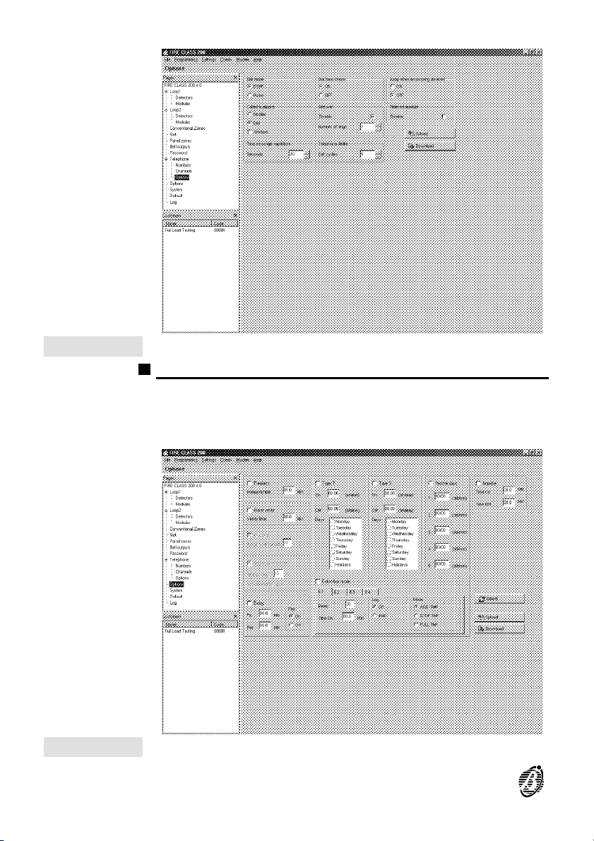
Figure 15 Telephone options window.
Options
The Options sheet (figure 16) will allow you to program the Options (refer
to "OPTION" in the INSTALLATION MANUAL).
Figure 16 Options sheet
22 Analogue Fire Control Panels FireClass
Page 23
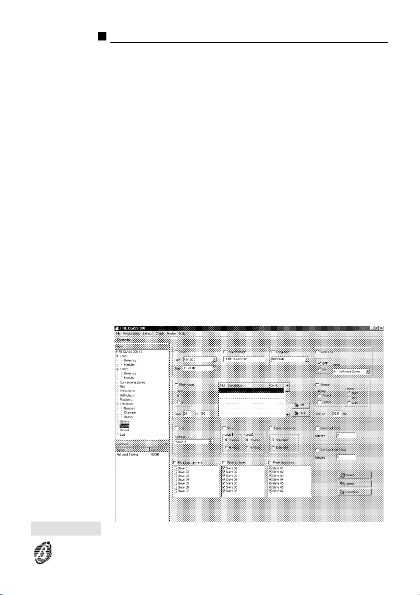
System
Use the System sheet (figure 17) to program:
Ø the system parameters (refer to "System" in the INSTALLATION MANUAL);
Ø the Welcome Message (refer to "Welcome Message" in the INSTALLA-
TION MANUAL);
Ø the Language used on the control panel display and Repeater panel display.
Alarm status
template
(Standard or
Extended)
Reset to Slave If this option is enabled, Reset, Silence and Confirm operations done at the
Reset from Slave If this option is enabled, Reset, Silence and Confirm operations done at a
Broadcast to
Slave
This option will allow you to select the Alarm status template: Standard or
Extended (refer to "Display Templates" in the "User Guide").
Master panel will affect selected or ALL the network Slave panels (in accordance with the setting in the respective template on the Master panel).
Slave panel will affect the Master, which in turn will broadcast the command to selected Slave panels (in accordance with the setting in the respective template on the Master panel).
If this option is enabled, the Master panel will retrieve the system events,
save them to the Master log then broadcast them to all its Slave panels except for the Slave panel it is communicating with. In this way, it will be possible to view the system status from all Slave panels (refer to "Centralized
Master Panel Log" in the "User Guide").
Figure 17 System sheet
Fire Software 23
Page 24
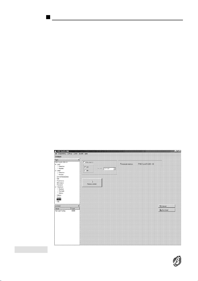
Factory
Use the Factory sheet (figure 18) to:
Ø program automatic Maintenance request;
Ø reset default settings;
Ø view the control panel Version (Refer to "Factory" in the INSTALLATION
MANUAL).
Figure 18 Factory sheet
24 Analogue Fire Control Panels FireClass
Page 25
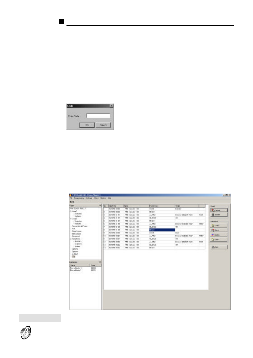
Log window
The Log window will allow you to:
Ø manage the control panel log;
Ø manage the open customer account log.
To open the Log window
1. Select Log from the Monitoring window.
2. Enter the Installer Code (00000 at default) or User Code (11111 at de-
fault).
If the code is valid the Log window (figure 19) will open and the application
will load the contents of the control panel log.
For each event the Log window shows:
Ø No. - the event number;
Ø Date/Time - the date and time on the control panel clock;
Ø Panel - the Label of the control panel which generated the event;
Figure 19 Log window
Fire Software 25
Page 26
Ø Event type - the event description;
Ø Origin - the Label, Loop, Type and Address of the device which generated
the event.
Control panel Log management
The buttons in the Panel box will allow you to manage the control panel
log.
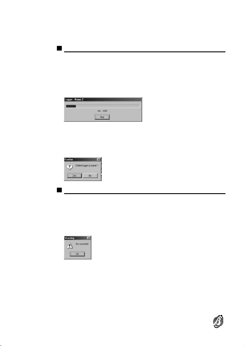
Load Select Upload from the Panel box - to Upload the events in the control
panel log. The events will be Uploaded starting from the oldest event to the
most recent.
Select Stop to stop event Uploading.
Delete Select Delete from the Panel box - to delete all the events in the control
panel log. The application will ask for confirmation before deleting.
Customer Account Log
The buttons in the Database box will allow you to manage the customer
account log.
If the customer account has not been loaded sucessfully, the following
+
warning will be shown.
Load Select Load from the Database box - to move the events from the open
customer account log to the Log window.
Save Select Save from the Database box - to save the events in the Log window
in the open customer account log.
26 Analogue Fire Control Panels FireClass
Page 27
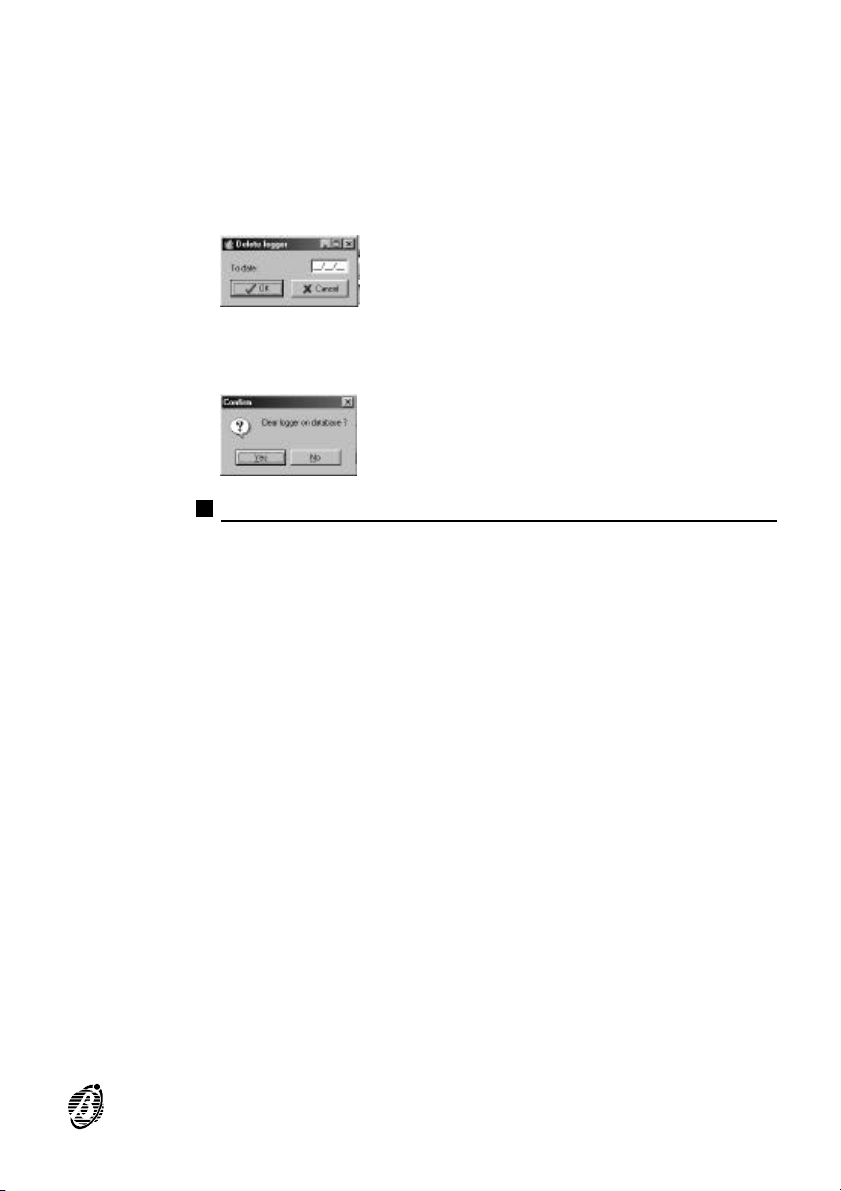
Save operations will save ONLY the new events in the customer account
+
log.
The event memory space of the customer log is limited, however, the database has a much greater capacity (depending on the hard disk).
Delete Select Delete to delete the events in the open customer account log.
Clear Select Clear to delete all the events in the open customer account log. A
Close Select Close to quit the Log window.
Events logged before and on the entered date will be deleted.
dialogue box will ask for confirmation before deleting.
Print and Close
Print Select Print to print-out a copy of the loaded events.
Fire Software 27
Page 28
Translat
The Translat application will allow you to customize:
Ø The terminology used in the Fire Software suite applications (Fire Soft-
ware, dbManager and GMap) is called the Program Language.
Ø The terminology used on the FireClass control panel display, and Repeater
panel display is called LCD Language.
The source language of the Translat application is English.
+
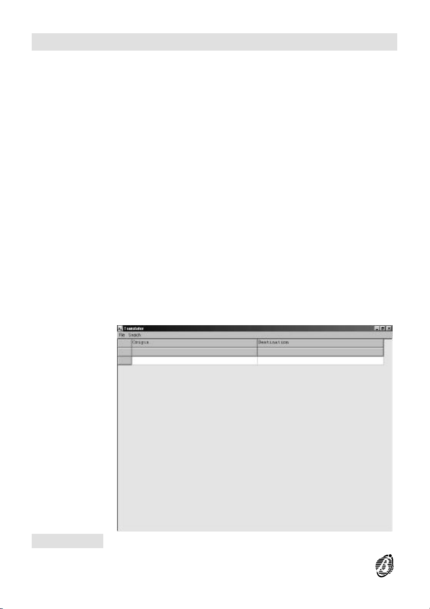
The Translator window of the Translat application (figure 20) provides the
File and Search menus (refer to "File" and "Search" paragraphs) and the
Origin and Destination columns
Ø The Origin column contains the application or LCD Origin language.
The words in the Origin column cannot be changed.
+
Ø The translation of the words in the Origin column must be entered in the
Destination column.
Figure 20 Translator window from the Translat application
28 Analogue Fire Control Panels FireClass
Page 29
File Menu
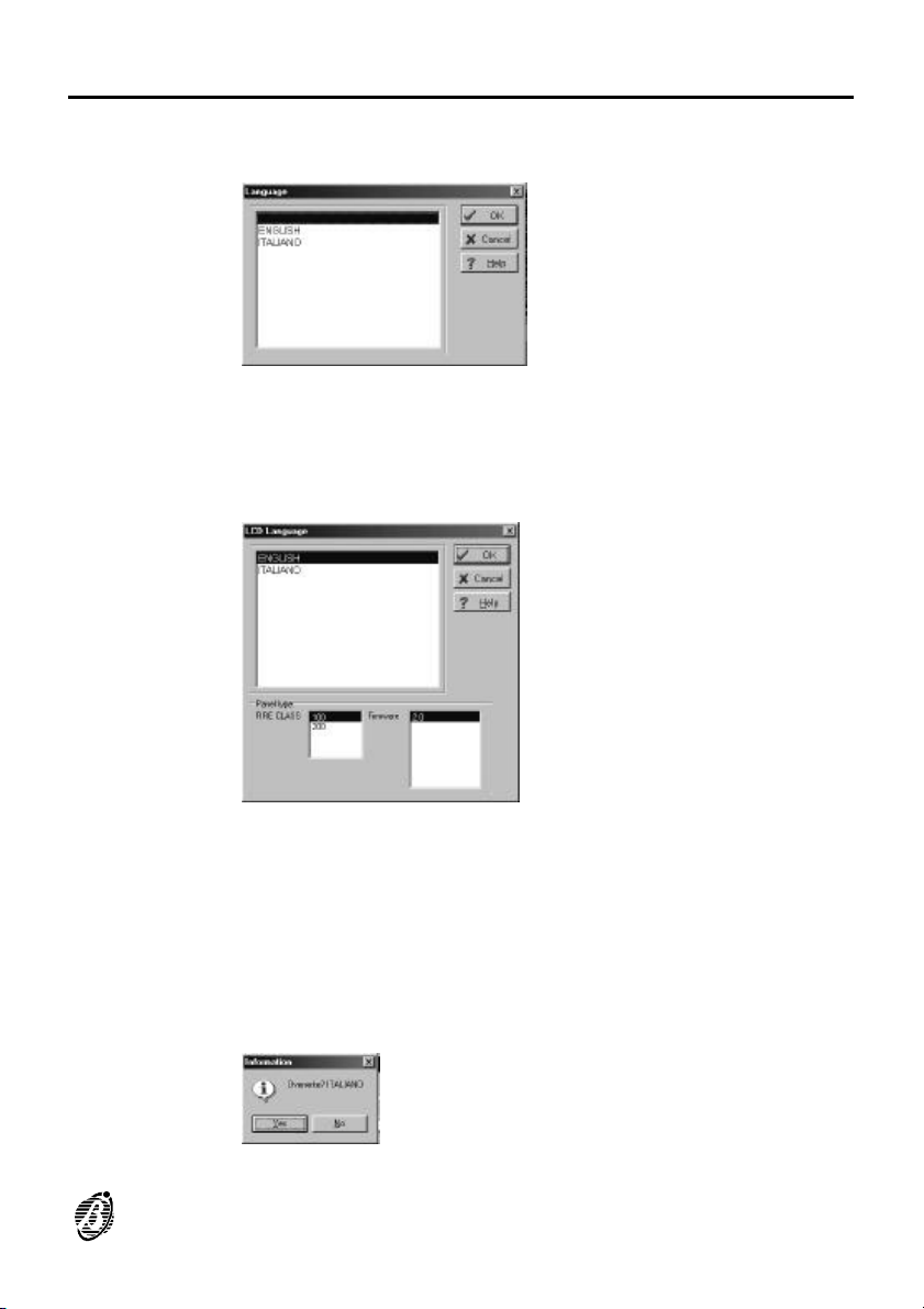
Open Origin Opens the Language window (see below) where you can select the Origin
Open Destination Opens the Language window (see above) where you can select the lan-
Open LCD > Origin Opens a window (see below) where you can select the LCD Language to
language for translation.
guage to be modified.
be translated.
Proper functioning of the LCD language depends on the FIRECLASS
+
model and on the Firmware version, therefore, both must be specified in
the Panel type box, as per above.
Open LCD >
Destination
Translat 29
Opens a window (see above) where you can select the language to be
modified
Save Saves (to the hard disk) the Destination language. A dialogue box will ask
for confirmation before saving.
Page 30
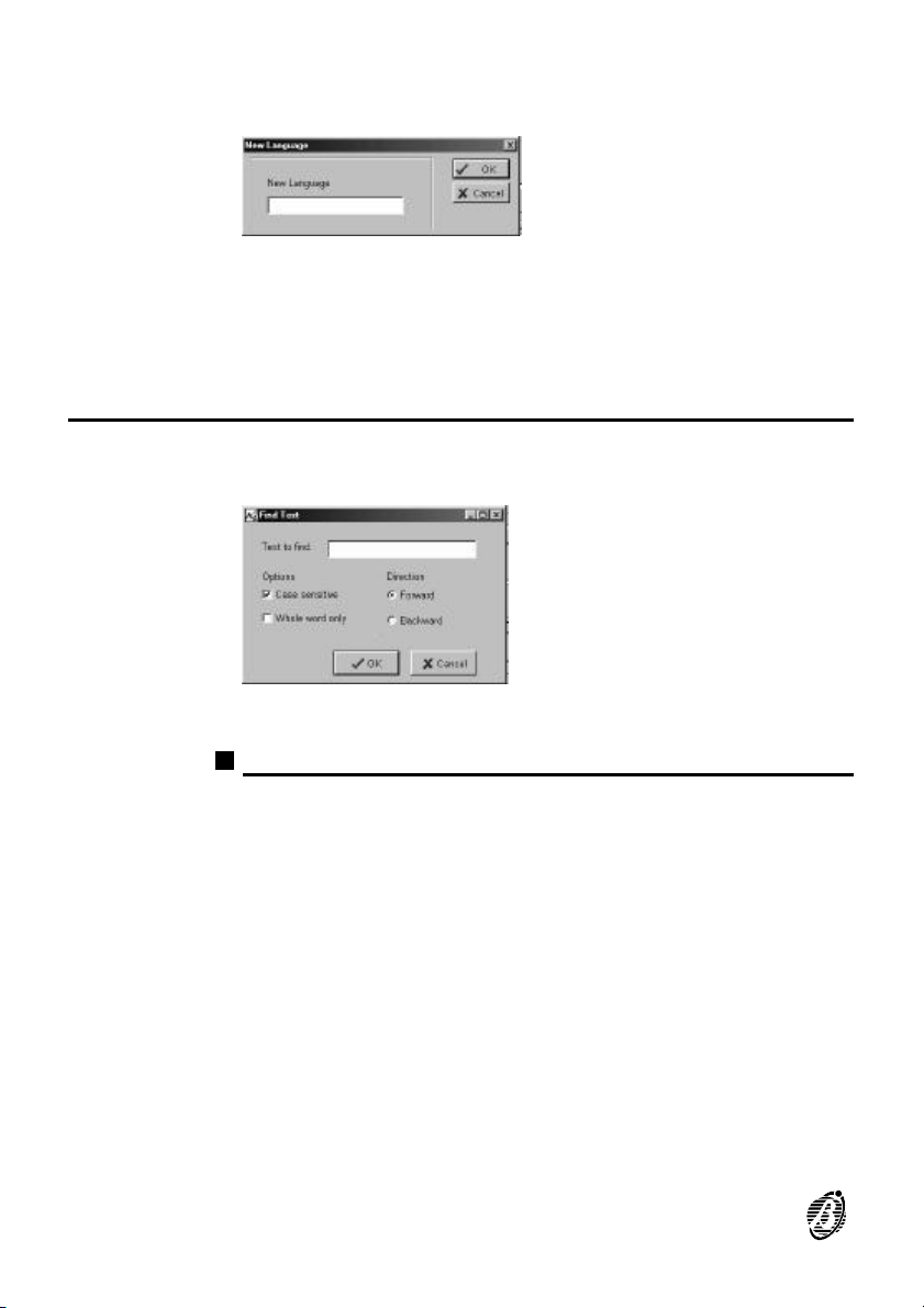
Save As Saves (to the hard disk) the Destination language using the name in the
Search Menu
Find Opens the Find Text window (see below) for the text search in the Origin
New language window (see below).
If you type in a name of an existing language, a dialogue box will ask for
confirmation before saving.
Exit Closes the application.
column.
Search Again Repeats the last Find Text request.
Find Text
To find text
Text to find Type in the Text.
Case sensitive Select Case sensitive to differentiate between upper-case and lower-case
Whole word only Select Whole word only to differentiate whole words from those sepa-
Forward Select Forward to scroll down.
Backward Select Backward to scroll up.
Cancel Select Cancel to quit the text search.
letters.
rated by a space.
OK Select OK to start text search.
30 Analogue Fire Control Panels FireClass
Page 31
Create language
Application
Language
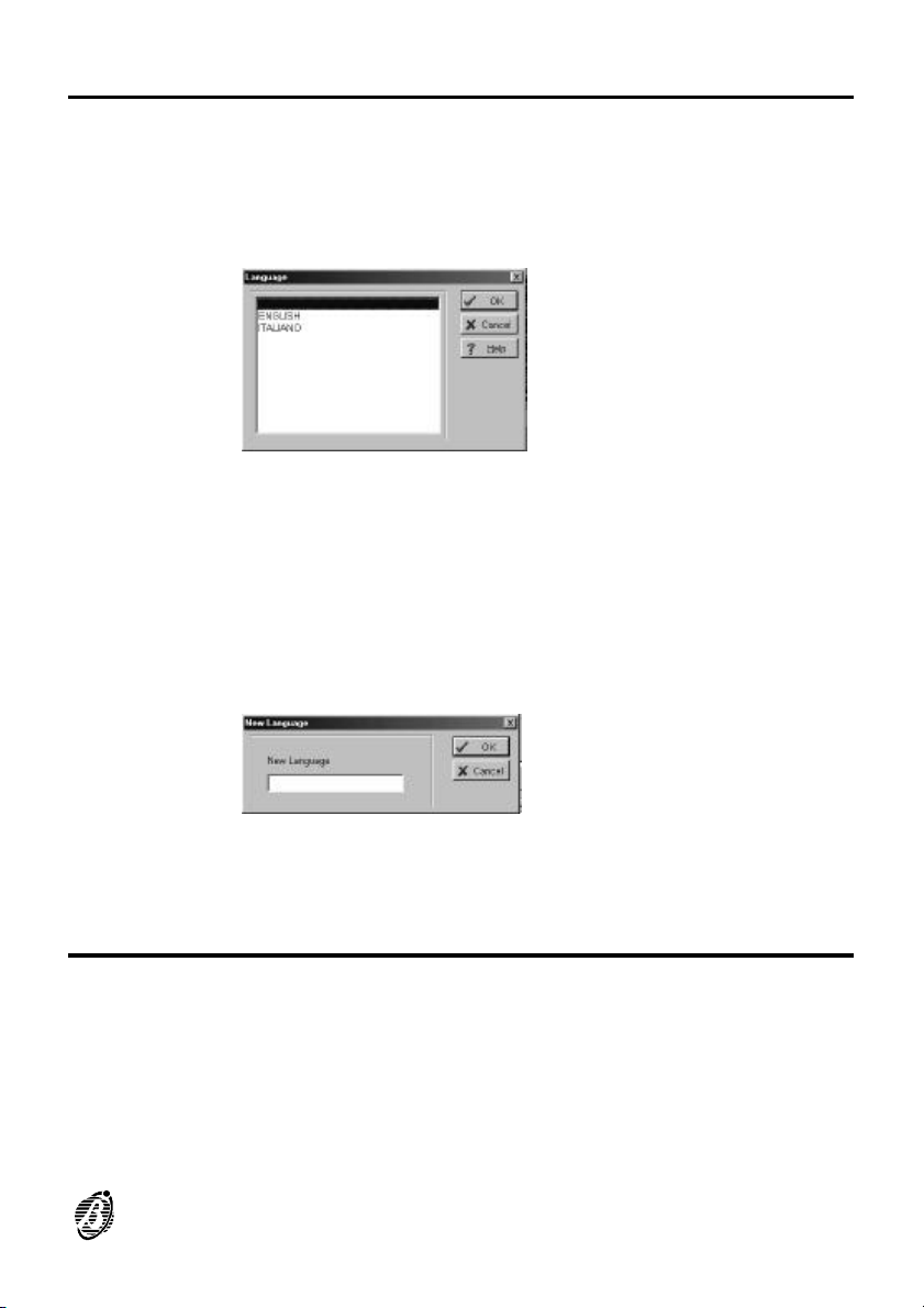
This option will allow you to assign the system language, as follows.
1. Select Open Origin from the File menu.
2. Select a source language from the Language window (see below).
3. The translation of the words in the Origin column must be entered in the
Destination column.
Words entered in the Destination column should have the same number
+
of letters, or less, than the words in the Origin column.
4. Select Save from the File menu.
5. Enter the name of the new language (maximum 8 letters) in the New Lan-
guage window (see below).
LCD Language To customize the LCD Language proceed as per "Application Language"
but at step 1. select Open LCD > Origin from the File menu.
Copy language
Application
Language
Translat 31
Creates a copy of the application Language.
To create a copy
1. Select Open Origin from the File menu.
2. Select a source language from the Language window.
Page 32
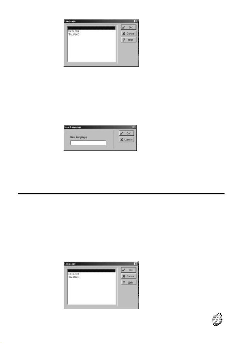
3. Select Open Destination from the File menu.
4. Select the language.
5. Select Save As from the File menu.
6. Enter the name (maximum 8 letters) of the copy in the New Language win-
dow (see below).
LCD Language To create a copy of the LCD language: proceed as per the "Application
Language" but at step 1. select Open LCD > Origin from the File menu,
but at step 3. select Open LCD > Destination.
Modify Language
Program
Language
This option will allow you to modify the application language.
To modify the application language
1. Select Open Origin from the File menu.
2. Select the Origin language from the Language window (an Origin language
can be opened contemporarily in the non-modifiable Origin column, and
also in the modifiable Destination column).
32 Analogue Fire Control Panels FireClass
Page 33
3. Select Open Destination from the File menu.
4. Select the required language from the Language window.
5. Modify the words in the Destination column.
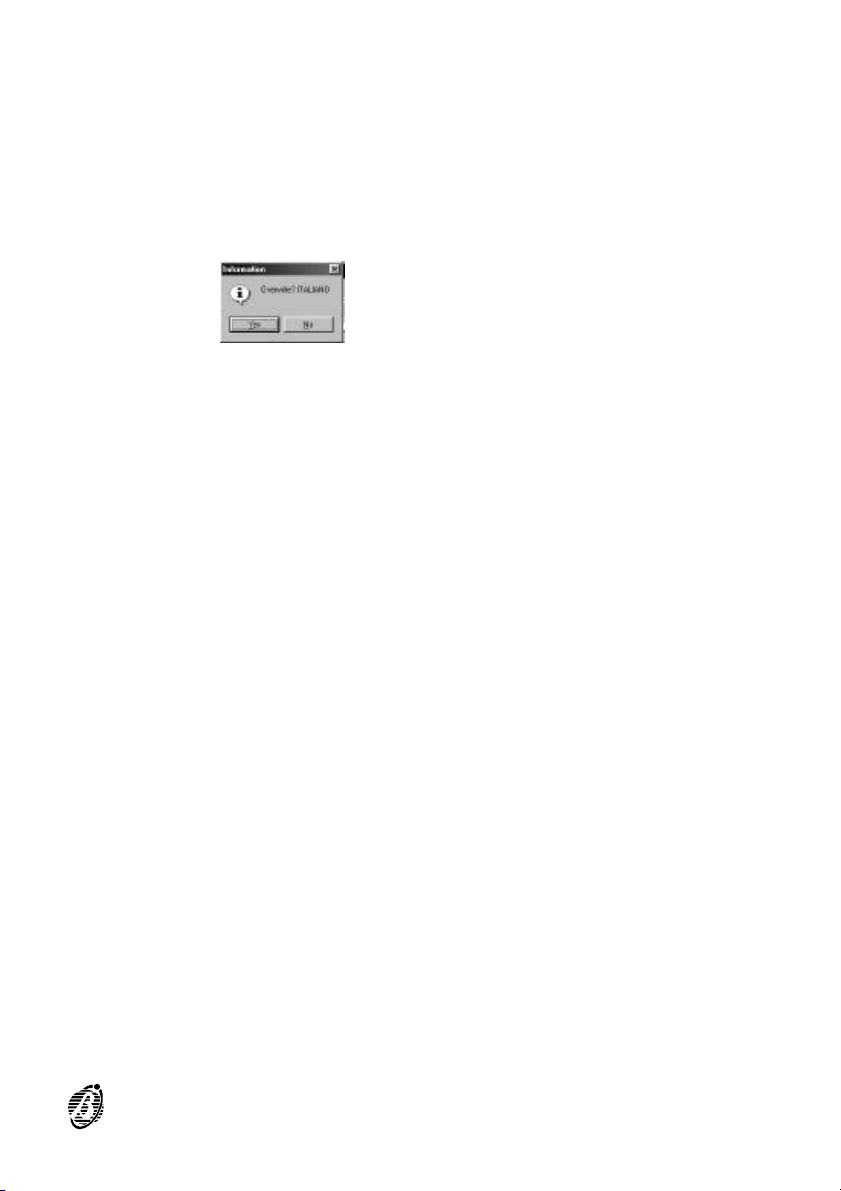
6. Select Save from the File menu.
7. Select Yes from the dialogue box (see below).
LCD Language To modify an LCD language: proceed as per "Application language" but at
step 1. select:
Ø Open LCD > Origin from the File menu.
and at step C
Ø Open LCD > Destination from the File menu.
Translat 33
Page 34

34 Analogue Fire Control Panels FireClass
Page 35
dbManager
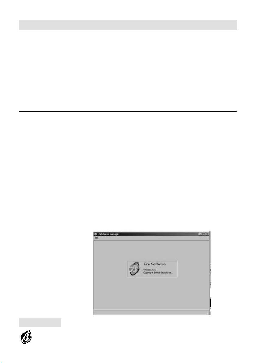
DbManager application copies customer account data from one folder to
another, and from one disk to another. For example, customer account
data can be copied from the PC hard disk to a floppy disk and used on a
portable PC.
The dbManager application provides the File menu only (see below).
File Menu
Export data Select Export data to copy customer account data (refer to "Export data").
Update database Reserved for future use.
Exit Select Exit to close the application.
Figure 21 Database manager window from the dbManager application
dbManager 35
Page 36
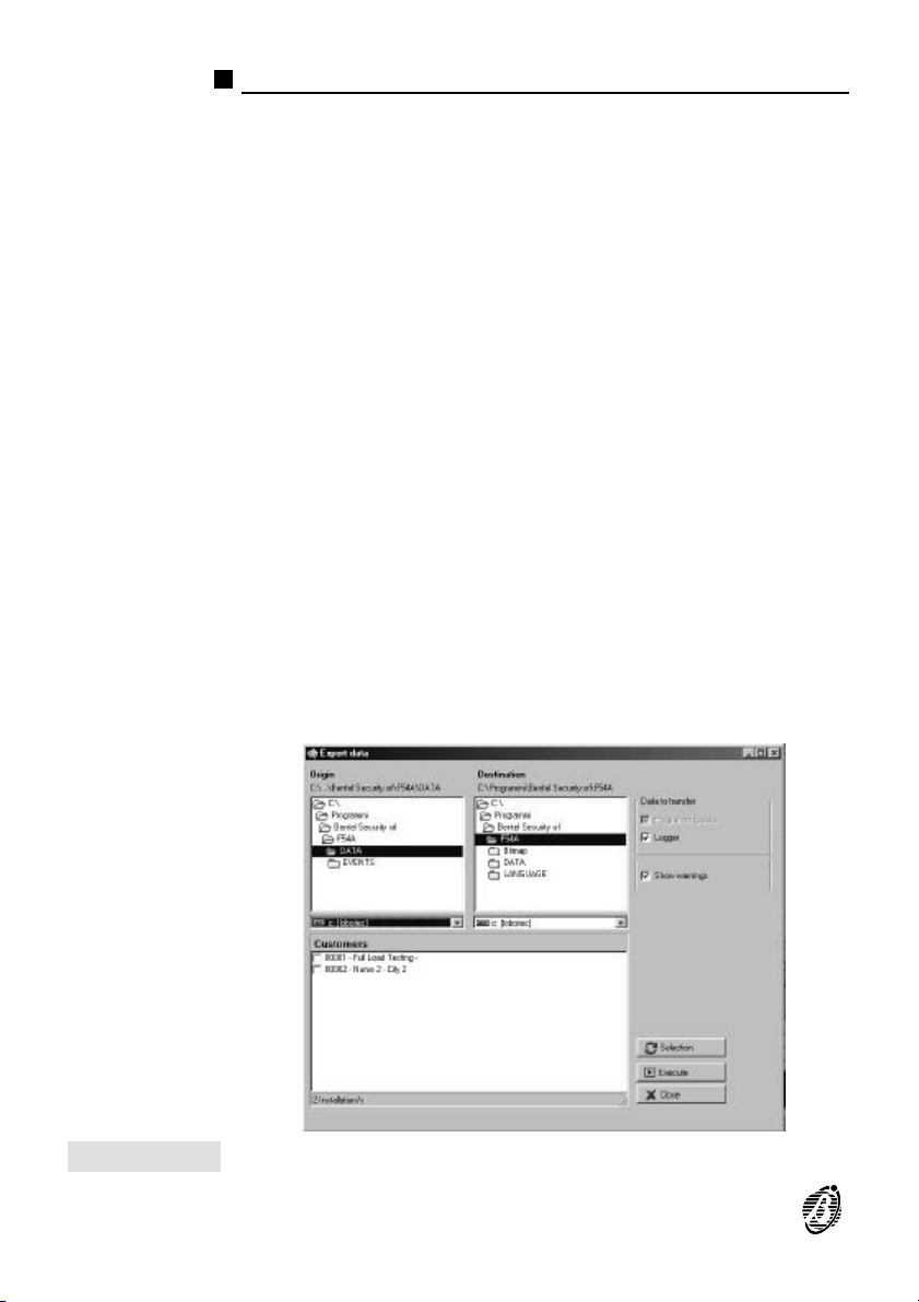
Export data
Export data from the File menu opens the Export data window described
below (see also figure 22).
Origin Select the disk and folder which contains the customer accounts con-
Customers Select the customer accounts concerned from the Customer account list.
Destination Select the destination disk and folder.
Data to transfer Select the data to export.
Show warnings Click on Show warnings if you want information regarding the risk of ex-
cerned.
The Fire Software application will save customer account data to the
+
\DATA installation folder of the Fire Software suite (Bentelfire).
To select/deselect ALL customer accounts click on Selection.
The customer accounts must be saved to the \DATA installaton folder of
+
the Fire Software suite (Bentelfire).
porting customer accounts ---- with duplicated Codes or Names ---- from
the Origin folder to the Destination folder.
Figure 22 The Export data window
36 Analogue Fire Control Panels FireClass
Page 37
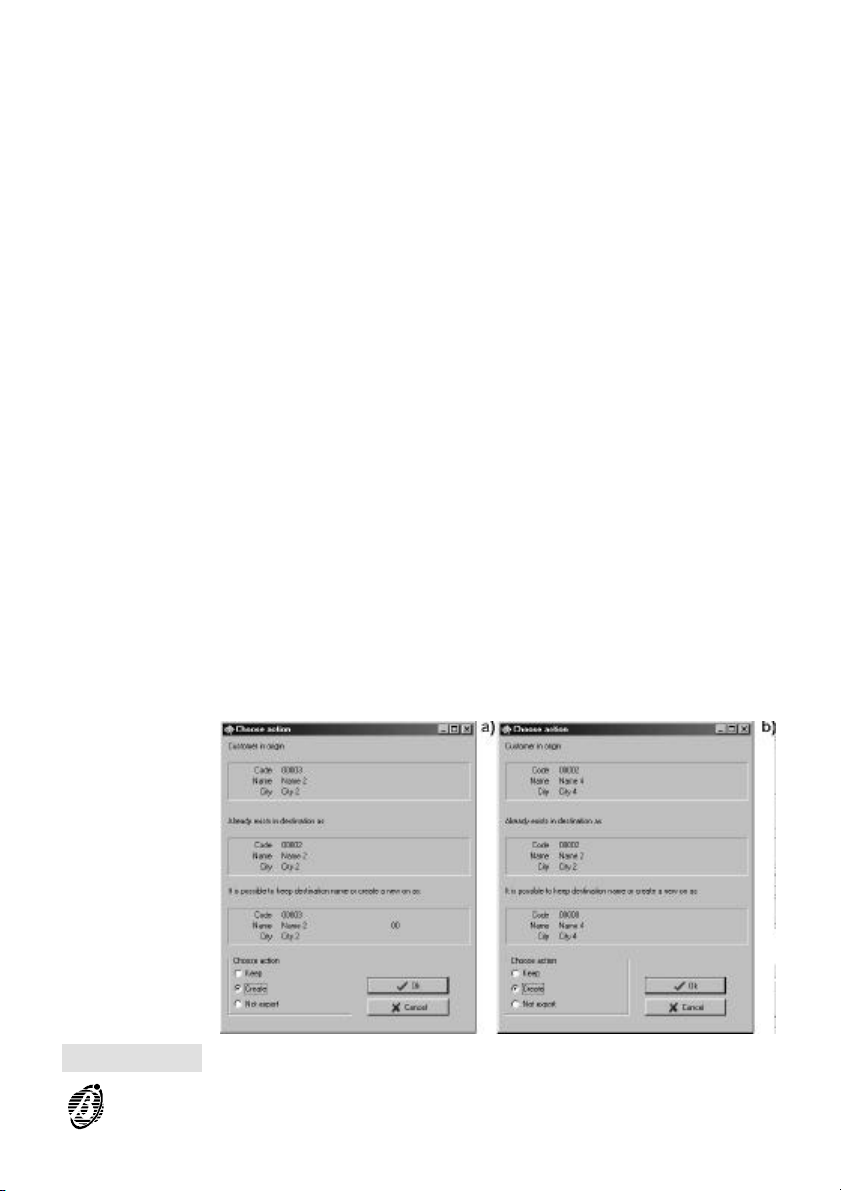
In the event of a duplicated Name but different Code ---- a window as per
figure 23a will open with the following options.
Ø Keep - the data of the customer account from the Origin folder will over-
write the data of the customer account with the duplicated Name in the
Destination folder.
Ø Create (at default) - the data will be saved as a new customer account
with the same Name but different Code as the customer account in the
Origin folder.
Ø Do Not export - the data will not be saved.
In the event of a duplicated Code but different Name ---- a window as per
figure 23b will open with the following options.
Ø Keep - the data of the customer account from the Origin folder will over-
write the data of the customer account with the duplicated Code in the
Destination folder.
Ø Create (at default) - the data will be saved as a new customer account with
the same Name but different Code as the customer account in the Origin
folder.
Ø Do Not export - the data will not be saved.
If you disable the Show Warning option, the application will enable the
+
Create option automatically.
Figure 23 Choose action window
dbManager 37
Page 38
Copying Customer accounts
To copy customer accounts
1. Select Export data from the File menu.
2. Select the disk and folder of the customer accounts concerned from the
Origin box.
3. Select the required customer accounts from the Customers box.
4. Select the destination disk and folder from the Destination box.
5. Select Log and/or Show warnings.
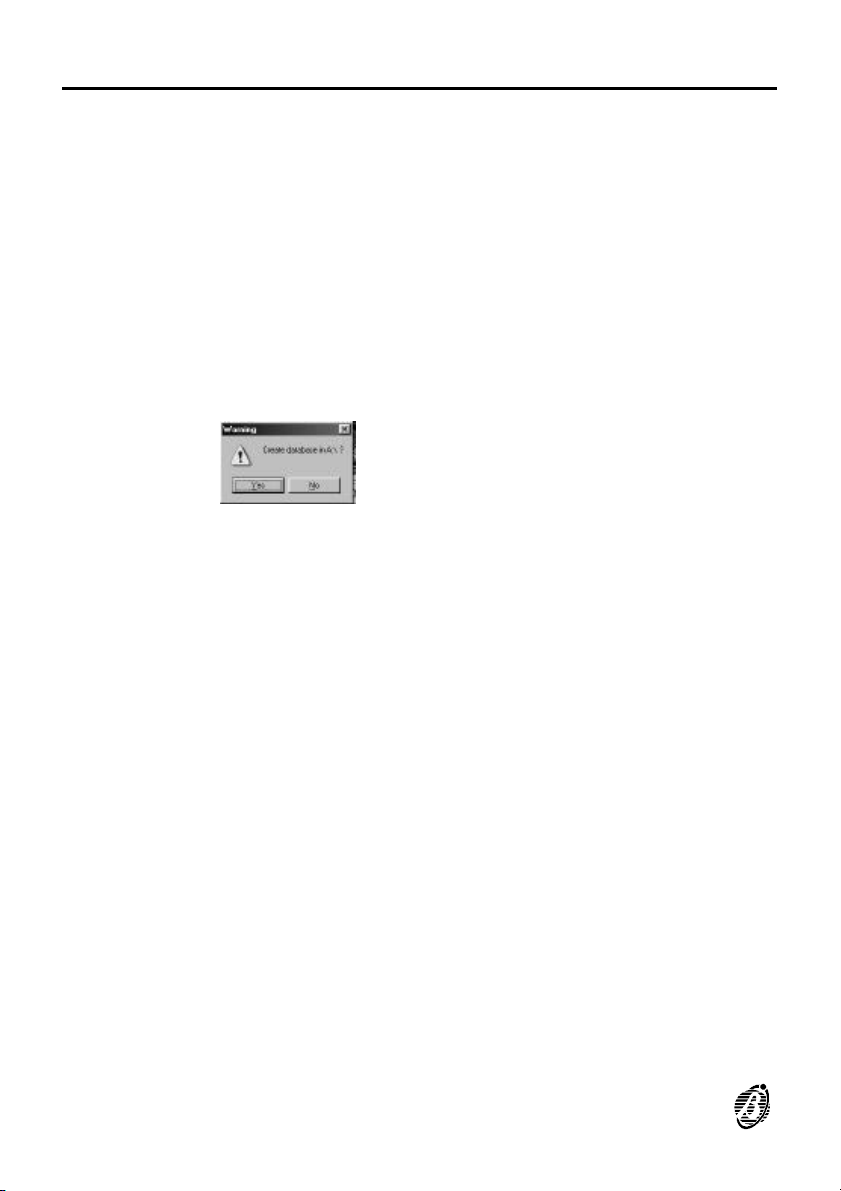
6. Select Execute - if there are no customer accounts in the Destination
folder, the following warning will be shown.
7. Select Yes to copy.
38 Analogue Fire Control Panels FireClass
Page 39
GMap
GMap is a monitoring application for FireClass systems.
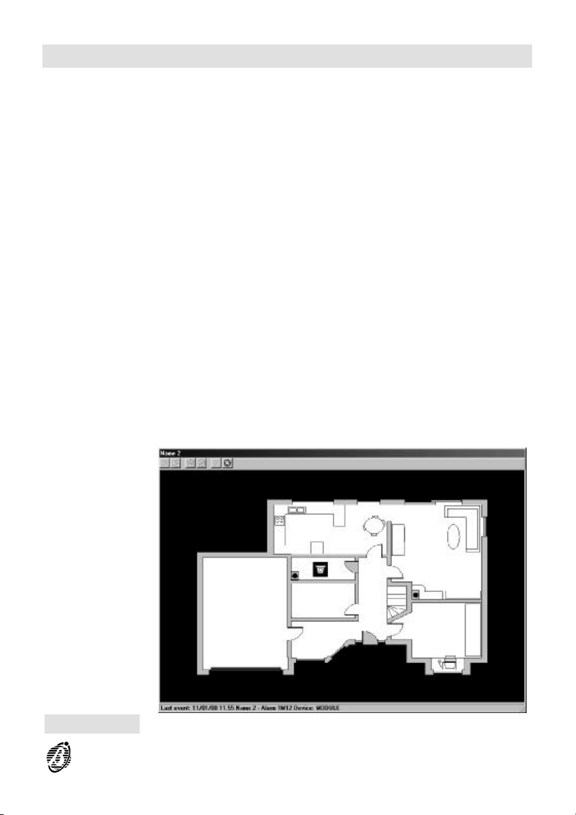
A Symbol must be assigned to each device on the system. The device
symbols must then be assigned to the Background (plan) of the protected
premises to create a Map.
When an event occurs the Map associated with the device that generated
the event (figure 24) will be shown, and will indicate the event type and exact location.
The bottom row of the Map window will also show the:
Ø Date and Time of the event;
Ø Customer Name;
Ø Event Type (Start, Pre-alarm, Warning, Alarm or Fault);
Ø Loop, Type, Address and Label of the device that generated the last
event.
If several events occur, you will be able to view the Loop, Type, Address,
+
Label and Event Type of each device, by positioning the cursor on the relevant Symbol.
Figure 24 Event shown on Map
GMap 39
Page 40
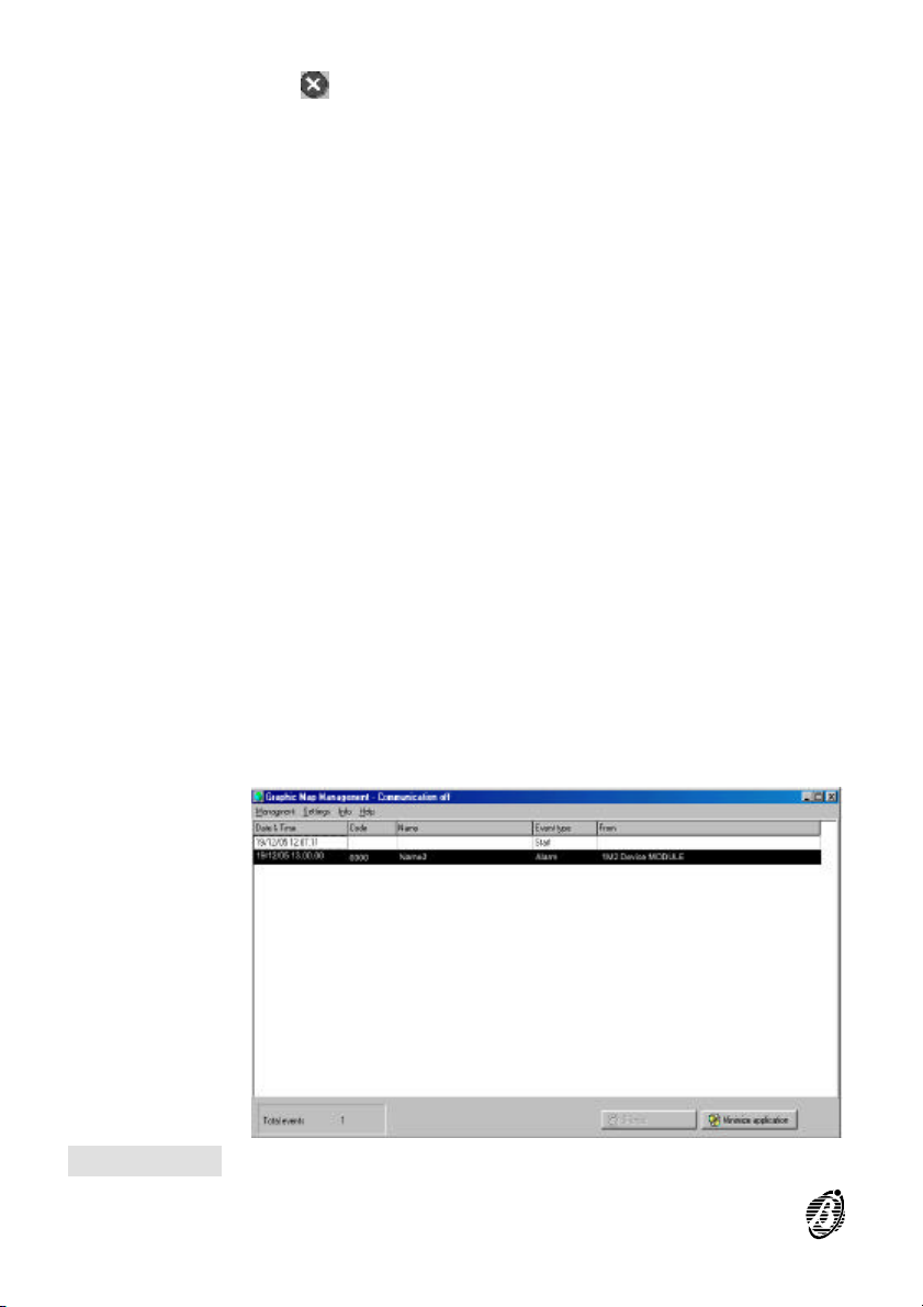
Select to close the Map and open the Graphic map Management
window.
The Management graphic map window (figure 25) will show the:
Ø Date and Time of the event;
Ø Customer Name and Code;
Ø Event Type (Start, Pre-alarm, Warning, Alarm or Fault).
Ø Loop, Type, Address and Label of the device that generated the event
(refer to From column).
Select Show Map from the Management menu for the Map of the se-
lected event.
The FireClass control panel need not be connected to the PC, nor is it nec-
essary to run the GMap application when making Maps.
Figure 25 Example of an event shown in the Graphic map management window
40 Analogue Fire Control Panels FireClass
Page 41
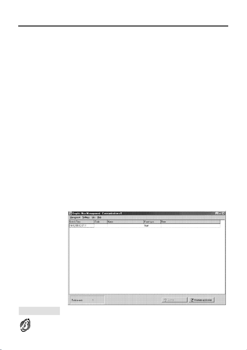
Graphic map management window
On Startup the GMap application is as per figure 26.
Date & Time Shows the PC Date and Time of the event.
Code Shows the Customer Code.
Name Shows the Customer Name.
Event Type Shows the Event Type (Start, Pre-alarm, Warning, Alarm or Fault).
From Shows the Loop, Type, Address and Label of the device that generated
Total events Shows the total events since application Startup.
Silence Select Silence to stop the acoustic signalling on the PC.
Minimize
application
the event.
Select Minimize application to run GMap in background.
Figure 26 Graphic management window from the GMap application
GMap 41
Page 42
Management menu
Clear list Deletes all the events listed in the Events window, except the Start event,.
Show map Shows the map, if present, for the selected event.
Exit Closes the GMap application.
Settings Menu
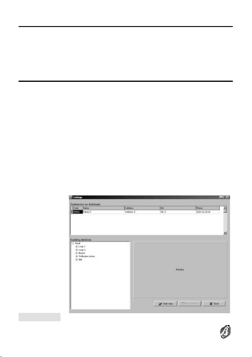
Maps Opens the Settings window (figure 27) described below.
Ø Customers on database - shows the Customers enabled for GMap moni-
toring (refer to the Enable graphic map management option from the
Customer account window > Fire Software application). Click on Code,
Name, Address, City or Phone to select the Customer.
Ø Existing devices - shows the device tree of the Customer selected from
Customers on database window.
Ø Preview - shows the Map, if existing, associated with the device selected
from the Existing devices window.
Ø Clear Map - deletes the Map associated with the device selected from the
Existing devices window.
Ø Map settings - opens the window where it is possible to make/change a
Map for the device selected in the Existing devices window.
Ø Close - Closes the Settings window.
Figure 27 Settings window
42 Analogue Fire Control Panels FireClass
Page 43
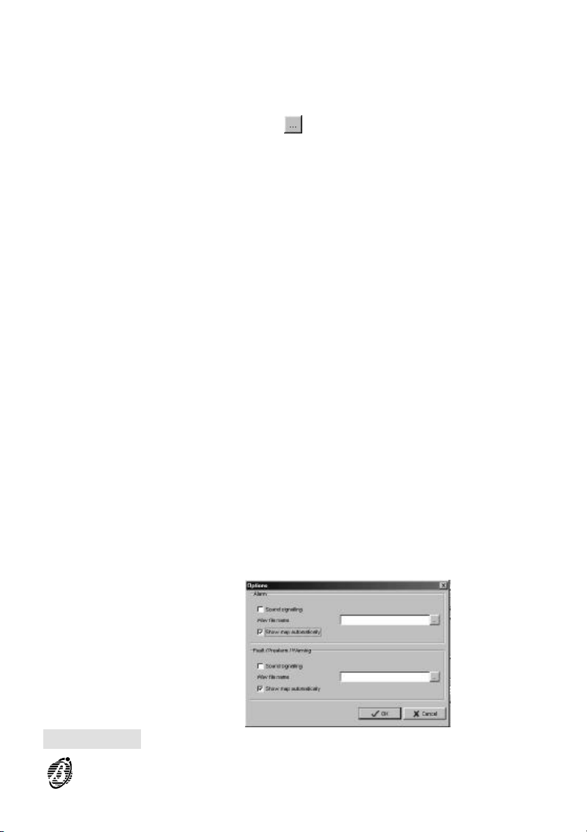
Options Opens the Options window (figure 28) described below.
Ø Sound signalling - if enabled the PC will emit the acoustic signal (se-
lected in the Wav file name box) in the event of an alarm (Fault, PreAlarm, Warning).
Ø Wav file name - click on and then select the required sound.
Ø Auto-show map on event - if enabled (enabled at default) the GMap ap-
plication will display the corresponding Map in the event of an alarm (Fault,
Pre-Alarm, Warning). If disabled - select Show map from the Manage-
ment menu to view the Map that corresponds to the selected event.
Figure 28 Options window
GMap 43
Page 44
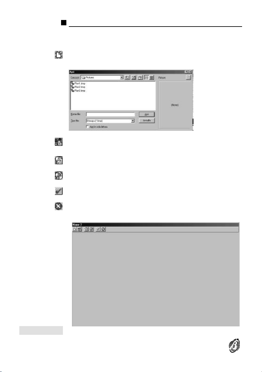
Map settings
The Map settings option from the Settings window opens a window as
per figure 29.
Background - opens a window, as per below, which will allow you to select the BMP file for the Map background.
Symbol - opens a window, as per above, where it is possible to choose
the BMP file for the Map symbol.
Show other symbols - shows other symbols on the background.
Hide other symbols - hides other symbols on the background.
OK - saves changes and closes the Map settings window.
Cancel - abandons changes and closes the Map settings window.
Figure 29 Map settings window
44 Analogue Fire Control Panels FireClass
Page 45
Create Map
New backgrounds
The GMap application offers several backgrounds.
To create new backgrounds
1.
Using a scanner or graphic application (CorelDRAW!, AutoCAD, Photoshop, etc.), design the background.
2. Save the background in Bitmap Windows 640 x 480 format or 800 x 600
pixel (16 colours), in the \Bitmap\PICTURES folder (Installation directory).
New Symbols
The GMap application provides many different symbols, however, you can
create new symbols as follows.
1.
Using a graphic application (CorelDRAW!, AutoCAD, Photoshop,
etc.), design the symbol.
2. Save the symbol in Bitmap Windows 32 x 32 pixel format, 16 colours, in
the \Bitmap\SYMBOLS folder (Installation directory Gmap application.
You must assign a Symbol to each device on the system. The device
symbols must then be assigned to the Background (plan) of the protected
premises in such a way as to create a Map.
To Create a Map
1. Select Maps from the Settings menu.
2. Select the Customer from the Customers on database window.
3. Select the device the Map is to be assigned to from Existing devices win-
dow.
4. Select Map settings;
5.
Select ;
6. Select the Map background.
7.
Select or to Show or Hide (respectively) the other symbols on the
background.
8.
Select .
GMap 45
Page 46
9. Select the device Symbol.
10. Move the symbol into the required position on the background.
11.
Select or to Save or Abandon (respectively) the settings and close
the Map settings window.
46 Analogue Fire Control Panels FireClass
Page 47

Notes
GMap 47
Page 48

ISTSOFFIREC/UK 1.0 151205 V4.2 BUZ
 Loading...