

Page 1
Page 2

BENTEL SECURITY srl reserves the right to modify the technical specifications of this product
without prior notice.
via Florida - Z.I. Valtesino - 63013 GROTTAMMARE (AP) - ITALY
USER MANUAL: Digital communicator control panels Omnia8/Omnia4
ISTRUZIONI INGLESE USO CEN. OMNIA4/8-UK ISTOMNIA4/8USO-UK
Page 3

CONTENTS
OVERVIEW 5
The Omnia8 and Omnia4 control panels . . . . . . . . . 5
Glossary . . . . . . . . . . . . . . . . . . . . . . . . . . 5
GENERAL FEATURES 7
The Main Unit . . . . . . . . . . . . . . . . . . . . . . . 7
The keypad . . . . . . . . . . . . . . . . . . . . . . . . . 7
Digital key . . . . . . . . . . . . . . . . . . . . . . . . 10
Arming Mode Options . . . . . . . . . . . . . . . . . . 10
DIGITAL KEY CONTROL 13
Global arming . . . . . . . . . . . . . . . . . . . . . . 13
Global disarming . . . . . . . . . . . . . . . . . . . . . 13
Type A arming (Amber) . . . . . . . . . . . . . . . . . 13
Type B arming (green) . . . . . . . . . . . . . . . . . . 14
Stop alarm . . . . . . . . . . . . . . . . . . . . . . . . 14
CONTROL FROM KEYPAD 15
Basic options . . . . . . . . . . . . . . . . . . . . . . 15
Global arming . . . . . . . . . . . . . . . . . . . . . . 16
Global disarming . . . . . . . . . . . . . . . . . . . . 16
Type A or Type B arming . . . . . . . . . . . . . . . . 16
Zone bypass . . . . . . . . . . . . . . . . . . . . . . 16
View armed partitions . . . . . . . . . . . . . . . . . . 17
View bypassed zones . . . . . . . . . . . . . . . . . 17
User Menu Options from keypad . . . . . . . . . . . . 18
Reset Alarm Memory . . . . . . . . . . . . . . . . . . 18
Enable / Disable auto arming . . . . . . . . . . . . . . 19
Enable / Disable Teleservice . . . . . . . . . . . . . . 19
Overtime Request . . . . . . . . . . . . . . . . . . . 20
Teleservice Request . . . . . . . . . . . . . . . . . . 20
Enable / Disable Silent keypad . . . . . . . . . . . . . 20
Enable / Disable Hidden zone status on keypad . . . . 20
3
Page 4
Alarm Device Test . . . . . . . . . . . . . . . . . . . 21
User Code PIN Programming . . . . . . . . . . . . . 21
Stop alarm . . . . . . . . . . . . . . . . . . . . . . . 22
Stop all Calls . . . . . . . . . . . . . . . . . . . . . . 22
Superkeys . . . . . . . . . . . . . . . . . . . . . . . . 23
Instant alarm call . . . . . . . . . . . . . . . . . . . . 23
View Alarm Memory . . . . . . . . . . . . . . . . . . 23
Trouble Viewing mode . . . . . . . . . . . . . . . . . 24
APPENDIX 25
Zones insert . . . . . . . . . . . . . . . . . . . . . . . 25
Programming sheets . . . . . . . . . . . . . . . . . . 25
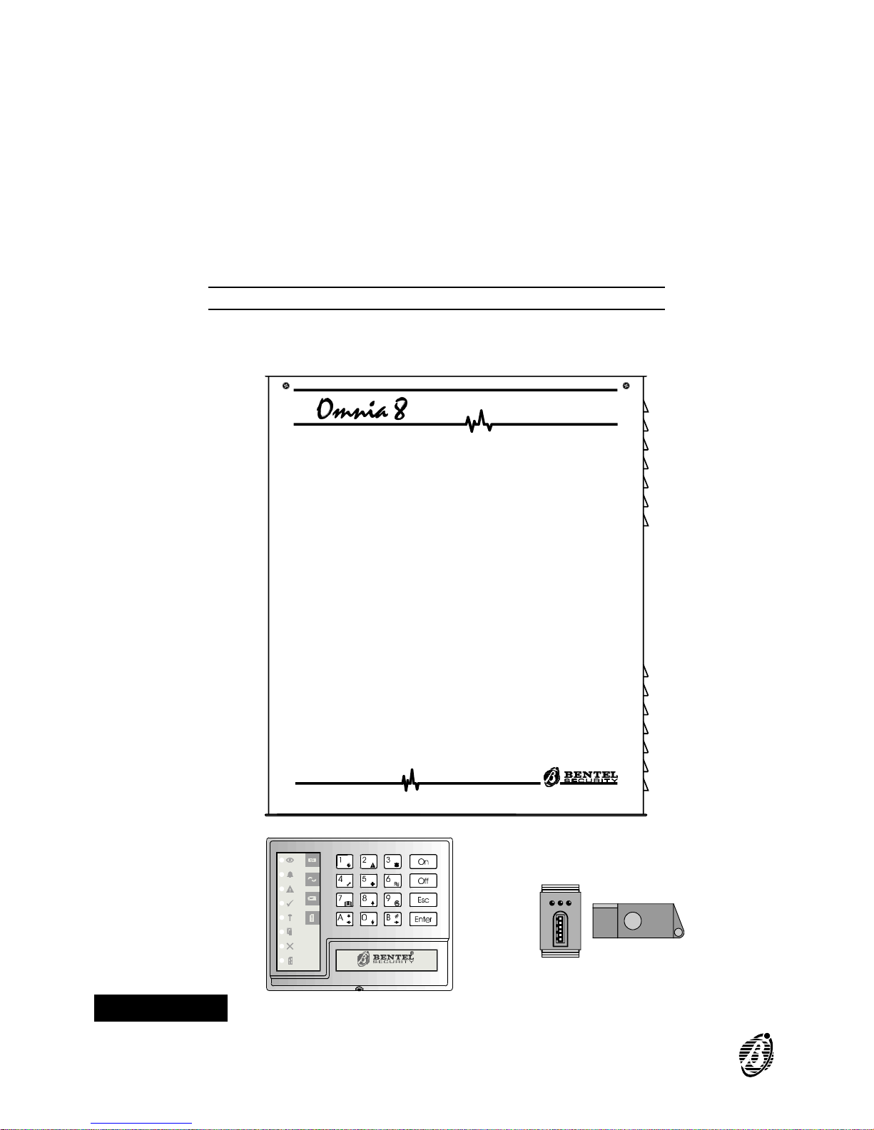
Figure 1 Omnia8 system components
4 Security System Control Panels Omnia8/Omnia4
Page 5

OVERVIEW
The Omnia8 and Omnia4 control panels
Omnia8 is a security system with 8 zones and 4 partitions. Omnia4 is a
security system with 4 zones and 4 partitions. The basic systems comprises a Main Unit, a built-in communicator and 1 keypad. The Control
panels can control up 16 remote devices (key readers / keypads), with a
maximum of 8 keypads including the one supplied, and 128 different digital
keys.
Communicator The built-in Digital Communicator can manage 8 telephone numbers for
communication with central stations and teleservice.
Voice messages The optional NormaVOX2 voice board can record and send up to 8 voice
messages to 1 or more of the 8 programmed telephone numbers.
All the Control panel features are described in this manual. Your Installer
will provide further details for proper use of the system.
Figure 1 shows a Omnia8 system with a Main Unit, keypad, key reader
and digital key. Digital keys, although not indispensable, greatly simplify
system control.
Glossary
Arming An option which puts the system IN SERVICE. Violation of the armed parti-
tions will generate an alarm.
Disarming An option which puts the system OUT-OF-SERVICE. Violation of the dis-
armed partitions will not generate an alarm.
Alarm A status which signals violation. Immediate intervention of authorized per-
sons will be required.
Keypad Set of keys (on keypad) used for manual control of the Omnia8 and Om-
nia4 systems.
Digital Key An electronic control key with a random code (selected from over 4 billion
combinations).
Key Reader A device which reads the digital key.
Alarm Zone A zone where one or more sensors can be connected.
Partition A group of zones that allow system partitioning, each partition can have its
own specific Times, Code PINs and digital keys.
OVERVIEW 5
Page 6
Exit Time A programmed delay which starts after the system arming.
ATTENTION! All persons must leave the protected zone before the
delay ends, otherwise the control panel will generate an alarm.
Entry Time A programmed delay which starts after violation of a delayed zone.
ATTENTION! The system must be disarmed before the delay ends.
Delayed Zone A zone which allows transit.
ATTENTION! An alarm will be generated if the programmed Exit /
Entry time is not respected.
Zone Bypass An option which excludes a zone.
ATTENTION! Violation of a bypassed zone will not generate an
alarm.
Tamper Zone A zone which is active 24 hours per day (24h zone), regardless of the
armed / disarmed status of the system. An alarm will be generated in the
event of tamper on any of the system components.
Alarm Memory A feature which records alarm events. The Alarm Memory can be cleared
by means of Automatic or Manual RESET.
Codes 23 Codes are available for the user. The Installer can assign one of the 5
Code Types: - DISABLED - MAIN USER - USER - DURESS - PATROL to
each of the 23 codes. Each code can control specific options and partitions
according to programming. Main User Type codes can assign a 4 to 6 digit
PIN to the other Code Types. When a Code PIN is entered on a keypad it
can enable / disable the options on the partitions it can control, and on the
partitions of the keypad in use.
User Pin A modifiable 4 to 6 digit number, programmed by the Main User, which can
access the system.
Installer Pin A modifiable 4 to 6 digit number which allows the Installer to access and
program the control panel parameters.
Teleservice A service provided by the Installer. The Teleservice feature allows the In-
staller to service the control pane via telephone.
Central Station A specialized operations centre that receives and responds to alarm sig-
nalling.
Telemonitoring A service provided by the Central Station. The Telemonitoring function is
for remote control of the system, and communicates coded events to the
Central Station.
6 Security System Control Panels Omnia8/Omnia4
Page 7
GENERAL FEATURES
The Main Unit
The Main Unit houses the main board, power supply unit, battery, and the
terminals for the connections of the Sensors, Sirens and auxiliary devices.
The keypad
The Control panel can be programmed and controlled from the keypads.
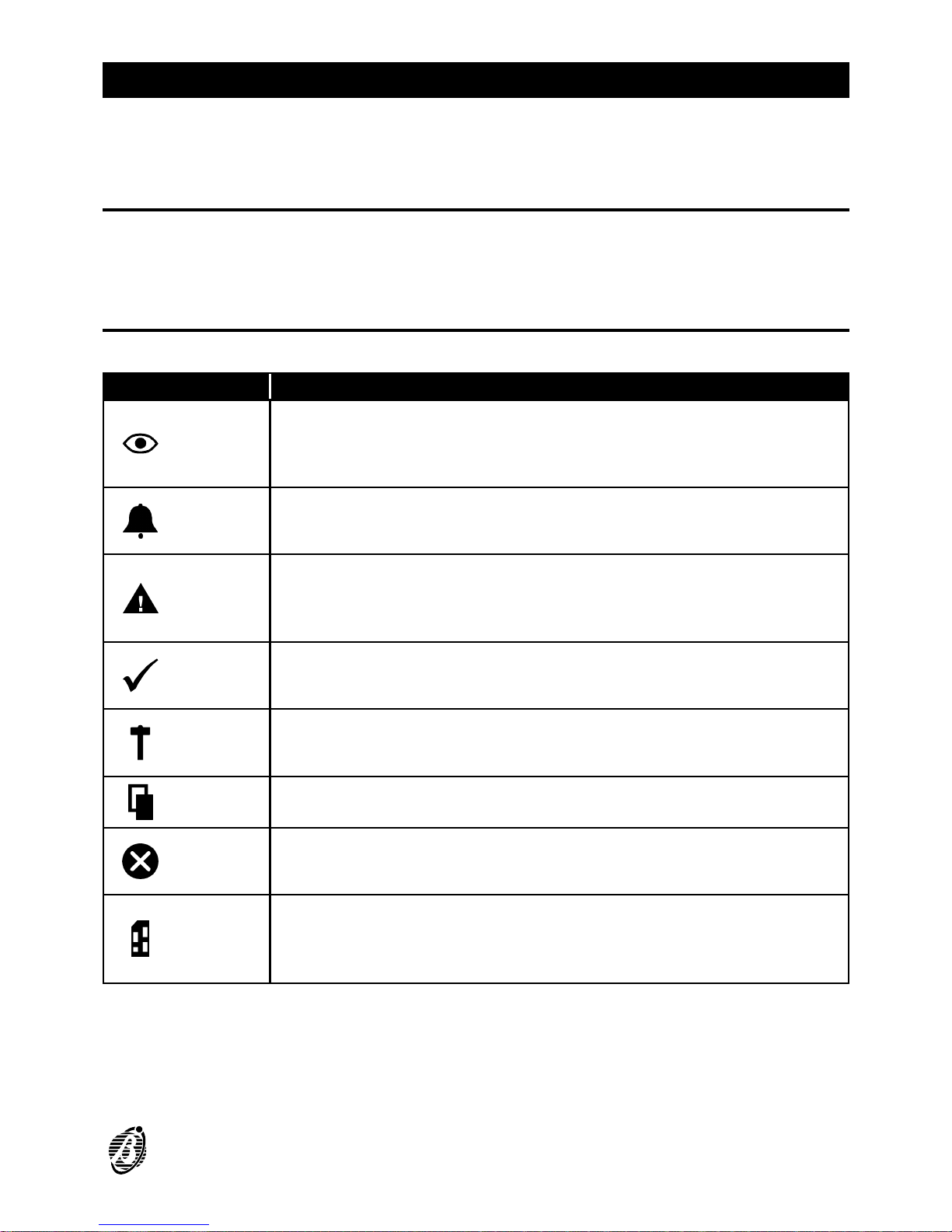
INDICATOR STATUS
Arm
OFF:
ON:
All partitions (enabled on the keypad) are
disarmed
At least one Partition (enabled on the keypad) is
armed
Alarm
OFF:
slow flashing:
fast flashing:
Standby status (no alarm)
Alarm memory
Alarm status
Trouble
OFF:
ON:
slow flashing:
No trouble
Trouble: use the Trouble Viewing Mode to identify
the trouble type
Trouble Viewing Mode running
Ready
ON:
OFF:
Ready to arm: ----arming will not generate an alarm
At least one unbypassed zone is in alarm status: ---arming will generate an alarm
24h
OFF:
slow flashing:
fast flashing:
Tamper line balanced
Alarm memorized on the tamper line
Alarm memorized and tamper line open
Open
NOT IN USE
Bypass
OFF:
ON:
slow flashing:
No bypassed zones
At least one of the keypad zones is bypassed
Control panel is ready for zone bypass
Program.
OFF:
ON:
slow flashing:
fast flashing:
Control panel in standby status
Control panel enabled for Teleservice calls
Control panel in programming status
Control panel in service status (maintenance)
GENERAL FEATURES 7
Page 8

INDICATOR TROUBLE VIEWING MODE
Key 1
OFF:
ON:
Sensor power protection fuse intact
Sensor power protection fuse blown
Key 4
OFF:
ON:
Main Unit powered by mains
Mains failure: Main Unit powered by battery
Key 7
OFF:
ON:
Battery charged
Low battery or battery trouble
Key A
OFF:
ON:
Communication bus normal
Communication bus trouble
Key 0
OFF:
ON:
Telephone line OK
Telephone line trouble
Number Keys
In standby status ----the LEDs behind number keys through (corresponding respectively to the zones) will show the zone status:
----OFF indicates zone in standby status
----Slow flashing indicates alarm or tamper memorized on the zone
----Fast flashing indicates zone violation (alarm or tamper)
Buzzer The audible signals emitted by the Keypad buzzer are as follows:
----Key pressed = Short beep
----Command accepted = Long high-tone beep
----Error signal = Long low-tone beep
The buzzer can also signal the elapsing Entry / Exit delay.
Codes 23 Codes are available for the user. The Installer can assign one of the 5
Code Types: - DISABLED - MAIN USER - USER - DURESS - PATROL to
each of the 23 codes. Each code can control specific options and partitions
according to programming. Main User Type codes can assign a 4 to 6 digit
PIN to the other Code Types. When a Code PIN is entered on a keypad it
can enable / disable the options on the partitions it can control, and on the
partitions of the keypad in use. Code errors will be signalled by a Long lowtone beep, after which it will be possible to retry.
r MAIN USER Codes provide full control of the system options, and can ac-
cess the programming phase and change the User Code PINs, therefore,
should be given to persons that require full control of the system.
r USER Codes are enabled for Global arming / disarming, Reset Alarm
Memory and Overtime requests. These Codes allow restricted control of
the system, therefore, should be given to persons that do not require full
control of the system.
r DURESS Codes are for forced disarming (disarming under threat). Entry of
a Duress Code PIN will disarm the system and activate the Digital Communicator (which will send an alarm call to the Central Station), and dialler
(which will send the recorded voice messages to the programmed telephone numbers).
8 Security System Control Panels Omnia8/Omnia4
Page 9

r PATROL Codes are enabled for Global arming / disarming. PATROL
Code PINs can disarm partitions temporarily. Partitions disarmed by a PA-
TROL Code PIN will be rearmed automatically when the programmed Patrol time elapses.
+
The factory default programming for the User Codes can be found on
page 26.
Superkeys Each Superkey controls a specific option (without requiring Code PIN en-
try): Number keys , , , and will take on Superkey status
when pressed for approximately 4 seconds (refer to "Superkeys" paragraph).
GENERAL FEATURES 9
Page 10

Digital key
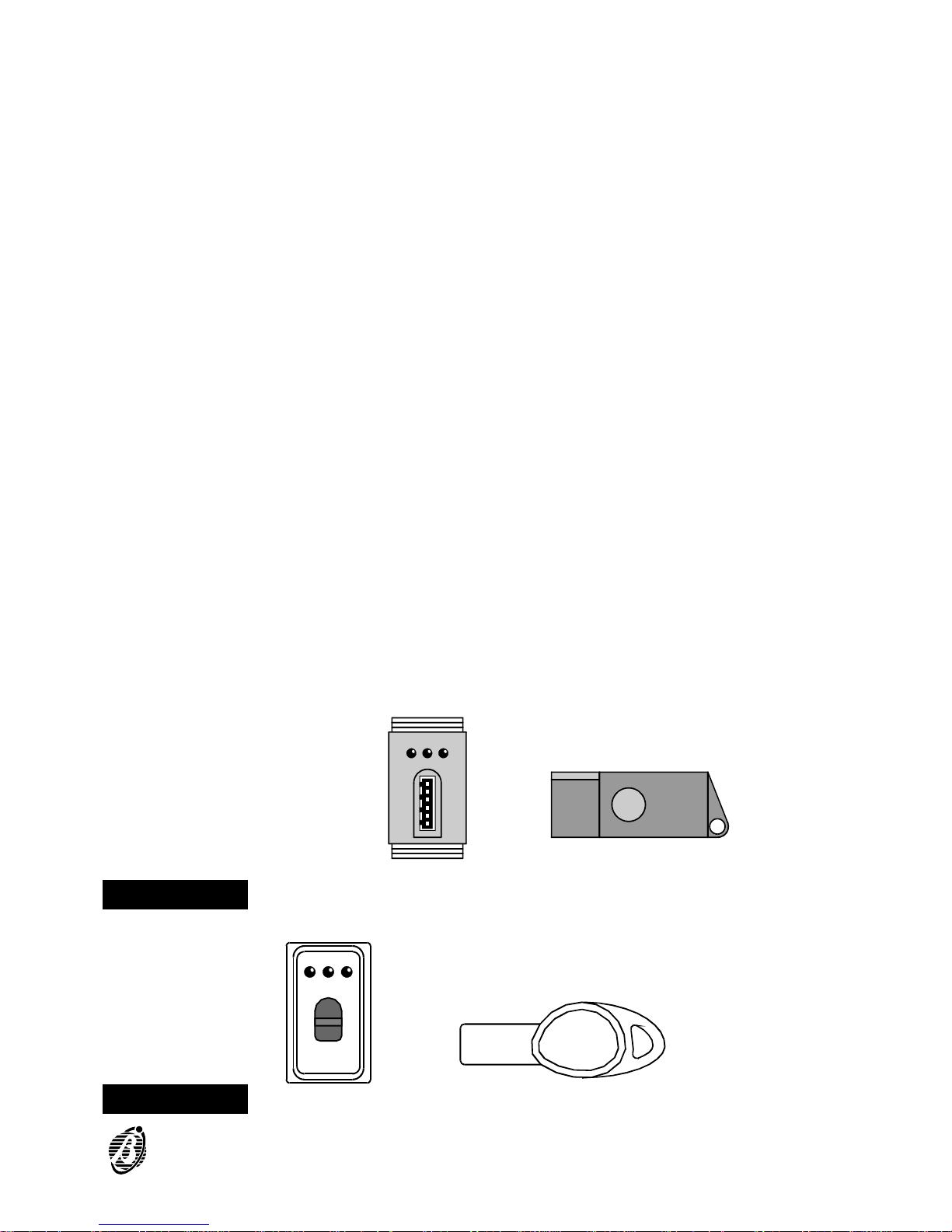
Key reader Key readers have 3 LEDs (Red, Green and Amber), and a digital key slot.
Each key reader will be programmed with the following:
-the partitions it can control
-the type of arming assigned to the Amber LED
-the type of arming assigned to the Green LED
Digital Key The digital keys control the arming mode of the partitions. The digital key
must be inserted into the key reader slot. It is possible to scan the 4 configurations of the LEDs (each configuration is assigned to a specific arming
mode) by simply pressing the digital key button. On the Eclipse/Sat model
the button is inside the key reader, therefore, the Sat digital key must be
inserted into the Eclipse key reader slot, and pushed lightly to scan the 4
configurations of the LEDs, and select the arming mode.
Digital keys have a non-volatile memory with a random code selected from
4 billion code combinations.
The Installer can assign a progressive number (1 through 128), and a 16
character Label to each of the 128 digital keys.
Each digital key can be programmed to control specific partitions only.
There are two digital key levels: Service ---- can stop all alarm types; and
Non-service ----can stop alarms on the partitions of the digital key and key
reader in use.
Multiple
Systems
Digital keys can valid on more than one system, and can be programmed to manage different groups of partitions on the different systems.
Arming Mode Options
Digital key in
key reader
When a valid digital key is inserted into a key reader, all the signalling devices of the partitions controlled by the digital key and key reader in use
will be stopped. At this point, by pressing the digital key button it will be
possible to scan the 4 configurations of the LEDs. Each configuration is assigned to a specific arming mode.
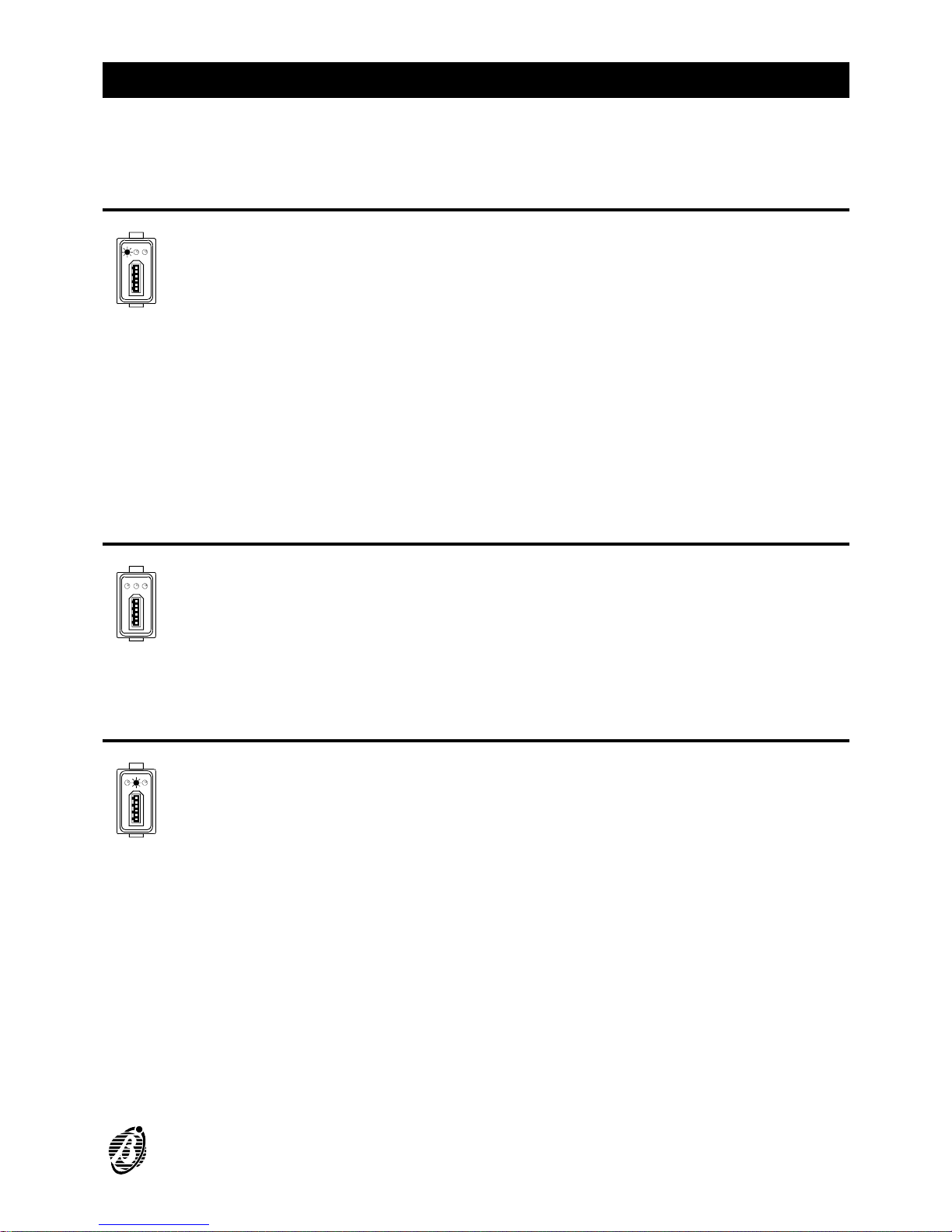
Ø Global arming: (Red LED ON) all the partitions controlled by the digital key
and key reader in use will be armed.
Ø Global disarming: (all LEDs OFF) all the partitions controlled by the digital
key and key reader in use will be disarmed.
Ø A and B type arming: (Amber or Green ON) all the partitions controlled by
the digital key and key reader in use will be armed or disarmed as configured during programming.
Ø Stop alarm: all signalling devices, connected to the alarm outputs of the
partitions controlled by the digital key and key reader in use will be forced
into standby status.
The selected arming mode (indicated by the configuration on the key
reader) will be activated when the digital key is extracted.
10 Security System Control Panels Omnia8/Omnia4
Page 11
The Control panel reads the status of the unbypassed and Instant zones
assigned to the partitions to be armed. If the zones are violated (door or
window open), the LED will start flashing to signal that arming the parti-
tions will generate an alarm.
To quit without changing:
1. Leave the key in the key reader.
2. Press the digital key button for about 4 seconds.
3. Extract the key when the 3 LEDs start flashing.
Invalid digital keys will generate the False Key Event on the key reader,
and will activate the programmed procedure. The False Key Event will be
signalled by fast flashing on the 3 LEDs.
No digital key in
key reader
When the key reader is empty (no digital key) the LEDs indicate the following:
----Red LED ON indicates that at least one of the partitions controlled by
the key reader is armed.
----Red LED OFF indicates that all the partitions controlled by the key
reader are disarmed.
----Amber LED ON indicates that the configuration of the armed or disarmed partitions matches the Type A arming mode of the key reader.
----Green LED ON indicates that the configuration of the armed or disarmed partitions matches the Type B arming mode of the key reader.
+
Only the partitions controlled by the key reader affect its LEDs. The LEDs
can be disabled by the Installer.
Figure 2 Key reader and digital key for control of the Control panel
Figure 3 Key reader and digital key for control of the Control panel - Eclipse/Sat model
GENERAL FEATURES 11
Page 12

+
If the configuration of the armed partitions does not match Type A or B
arming (for example a key reader partition has been armed from the keypad) the Amber and Green LED will be OFF.
12 Security System Control Panels Omnia8/Omnia4
Page 13
DIGITAL KEY CONTROL
Global arming
This option arms all the partitions that the digital key and key reader in use
can control.
1. Insert a valid digital key into any key reader ----all 3 LEDs on the key
reader will go OFF.
2. Press the digital key button once ----the Red LED will go ON to indicate a
Global arming request.
3. Extract the digital key ----the controlled partitions will arm.
+
Flashing on the Red LED signals that at least one zone is violated (door or
window open), and therefore, arming will generate an alarm.
Global disarming
This option disarms all the partitions that the digital key and key reader in
use can control.
1. Insert a valid digital key into any key reader ----all 3 LEDs will go OFF.
2. Extract the digital key ----the controlled partitions will disarm.
Type A arming (Amber)
This option arms specific partitions and disarms others according to the
programmed configuration.
1. Insert a valid digital key into any key reader -----all 3 LEDs will go OFF.
2. Press the digital key button twice ----the Amber LED will go ON to indicate
a Type A arming request.
3. Extract the digital key ----the system will arm with Type A arming configuration.
+
Flashing on the Amber LED signals that at least one zone is violated (door
or window open), and arming will generate an alarm.
DIGITAL KEY CONTROL 13
Page 14
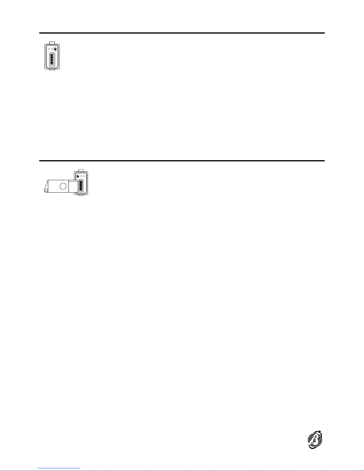
Type B arming (green)
This option will arm specific partitions and disarm others according to the
programmed configuration.
1. Insert a valid digital key into any key reader ----all 3 LEDs will go OFF.
2. Press the digital key button three times ----the Green LED will go ON to
indicate a Type B arming request.
3. Extract the digital key ----the system will arm with Type B arming configuration.
+
Flashing on the Green LED indicates that at least one zone is violated
(door or window open), and therefore, arming will generate an alarm.
Stop alarm
To stop an alarm:
Insert a valid digital key into any key reader.
Service digital keys can stop all alarm types (partition and system). Nonservice digital keys can only stop alarms on the partitions controlled by the
digital key and key reader in use.
This operation will affect the alarm memory.
14 Security System Control Panels Omnia8/Omnia4
Page 15
CONTROL FROM KEYPAD
The Omnia8 and Omnia4 systems can be controlled completely from the
keypad. The Control panels offer basic options, such as: arm / disarm etc.,
and also a set of options for advanced control of the system.
Basic options
To access basic options from standby status:
1. Enter User Code PIN (4 to 6 digits).
2. Select the option Key.
+
The keypad will lock for 3 minutes after 10 invalid code entries.
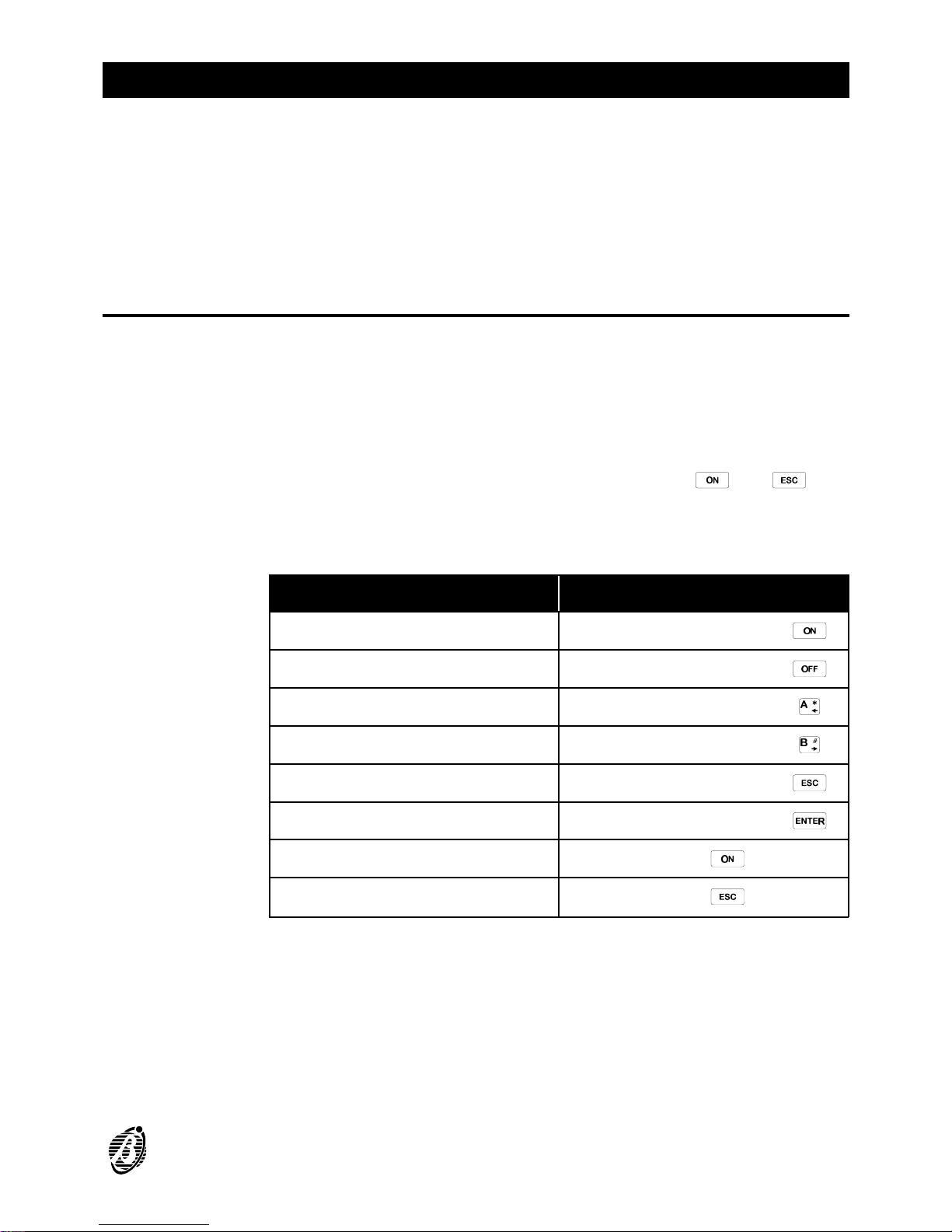
User Code PINs can control the 6 basic options. The and keys
can control 2 options, as per the table below.
Options that require a Code PIN will only affect the partitions controlled by
the Code PIN and the keypad in use.
OPTION PROCEDURE
Global arming
Enter Code PIN then press
Global disarming
Enter Code PIN then press
Type A arming
Enter Code PIN then press
Type B arming
Enter Code PIN then press
Access bypass zone menu
Enter Code PIN then press
Access User menu
Enter Code PIN then press
View armed Partitions
Press
View bypassed zones
Press
+
All Default PINs must be changed (refer to "User Code PIN Programming").
CONTROL FROM KEYPAD 15
Page 16

Global arming
<Code PIN>+
This option arms all the partitions controlled by the Code PIN and the keypad in use.
+
Before starting the procedure make sure that the Green READY LED is
ON (no zones violated).
1. Enter a Main User or User Code PIN.
2.
Press .
All the partitions controlled by the Code PIN and keypad in use will arm.
The keypad buzzer will signal the elapsing delay (EXIT TIME).
Global disarming
<Code PIN>+
This option disarms all the partitions controlled by the Code PIN and the
keypad in use.
1. Enter a Main User, User, Duress or Patrol Code PIN.
2.
Press .
All the partitions controlled by the Code PIN will disarm.
All Signalling Devices, activated by a partition alarm, will be forced into
standby status when the partition in question is disarmed.
If a Patrol Code PIN is used, the disarmed partitions will rearm automat-
ically when the Patrol time ends.
+
Duress Code PINs should only be used when the User’s personal safety
is at risk. Duress Code PINs will disarm the system, and at the same time
activate the Digital Communicator and Voice Dialler.
Type A or Type B arming
<Code PIN>+ or
During the programming phase each Code will be configured for Type A
arming and Type B arming. The configuration determines the partitions
that will arm and disarm when a Type A or Type B arming request is made.
Example: Type A arming configuration = arm partitions 1 and 4; disarm
partitions 2 and 3.
1. Enter a Main User, User or Duress Code PIN.
2.
Press or .
The Control panel will arm with Type A or B arming configuration.
Zone bypass
<Code PIN>+ +zone no.
The zone bypass option allows the User to bypass specific zones. Only
zones assigned to the partitions, and controlled by the Code PIN and keypad in use can be bypassed / unbypassed.
16 Security System Control Panels Omnia8/Omnia4
Page 17

Before accessing the zone bypass menu disarm the partition that the
zone is assigned to, otherwise, the zone bypass request will be revoked.
1. Enter a Main User Code PIN.
2.
Press to access the Bypass menu.
The Amber LED ESC will flash slowly.
The current zone status (bypassed / unbypassed) will be shown on num-
ber keys through (assigned respectively to zones 1 through 8):
----ON indicates zone bypassed
----OFF indicates zone unbypassed
3. Bypass / unbypass the zones as required ----use the number Key to toggle
the status of its assigned zone.
4.
Press to quit and step back to standby status.
The control panel will step back automatically if no key is pressed within 20
seconds of access.
View armed partitions
To view partition status (armed / disarmed):
1.
Press to view the armed partitions.
The key will flash.
The current partition status (armed / disarmed) will be shown on keys
through (assigned respectively to partitions 1 through 4):
----ON indicates partition armed
----OFF indicates partition disarmed
2.
Press the key to step back to standby status.
The control panel will step back automatically if no key is pressed within 20
seconds of access.
View bypassed zones
To view zone status (bypassed / unbypassed):
1.
Press the key to view zone status.
The key will flash slowly.
The current zone status will be shown on keys through (assigned
respectively to zones1 through 8):
----ON indicates zone bypassed
----OFF indicates zone unbypassed
2.
Press the key to step back to standby status.
The control panel will step back automatically if no key is pressed within 20
seconds of access.
CONTROL FROM KEYPAD 17
Page 18

User Menu Options from keypad
<Code PIN>+
Only Main User Code PINs have full access to all the options. User Code PINs
can access two options only: Reset Alarm Memory and Overtime Request.
To access options:
1. Enter a Main User or User Code PIN.
2.
Press .
3. Select the required option.
Options from__
keypad__
r Reset Alarm Memory
r Enable / Disable auto arming
r Enable / Disable Teleservice
r Overtime Request
r Teleservice Request
r Enable / Disable Silent option
r Enable / Disable hidden zone status on keypad
r Alarm Device Test
r Code PIN Programming
r Stop Alarms
r Stop Calls
+
The Options will affect the partitions controlled by the Code PIN and keypad in use.
Reset Alarm Memory
<Code PIN>+ +
All zone alarms are recorded in the alarm memory. The Reset Alarm Memory option erases the alarm memory, and forces the Alarm Signalling Devices (connected to the alarm outputs) of the partitions controlled by the
Code PIN into standby status.
To Reset Alarm Memory:
1. Enter a Main User or User Code PIN.
2.
Press .
3.
Press .
+
Only Main User Code PINs can Reset the System Tamper Alarm Memory.
ATTENTION The Control panel will effect Reset Alarm Memory each
time the control panel is armed, that is, if so programmed by the Installer.
18 Security System Control Panels Omnia8/Omnia4
Page 19
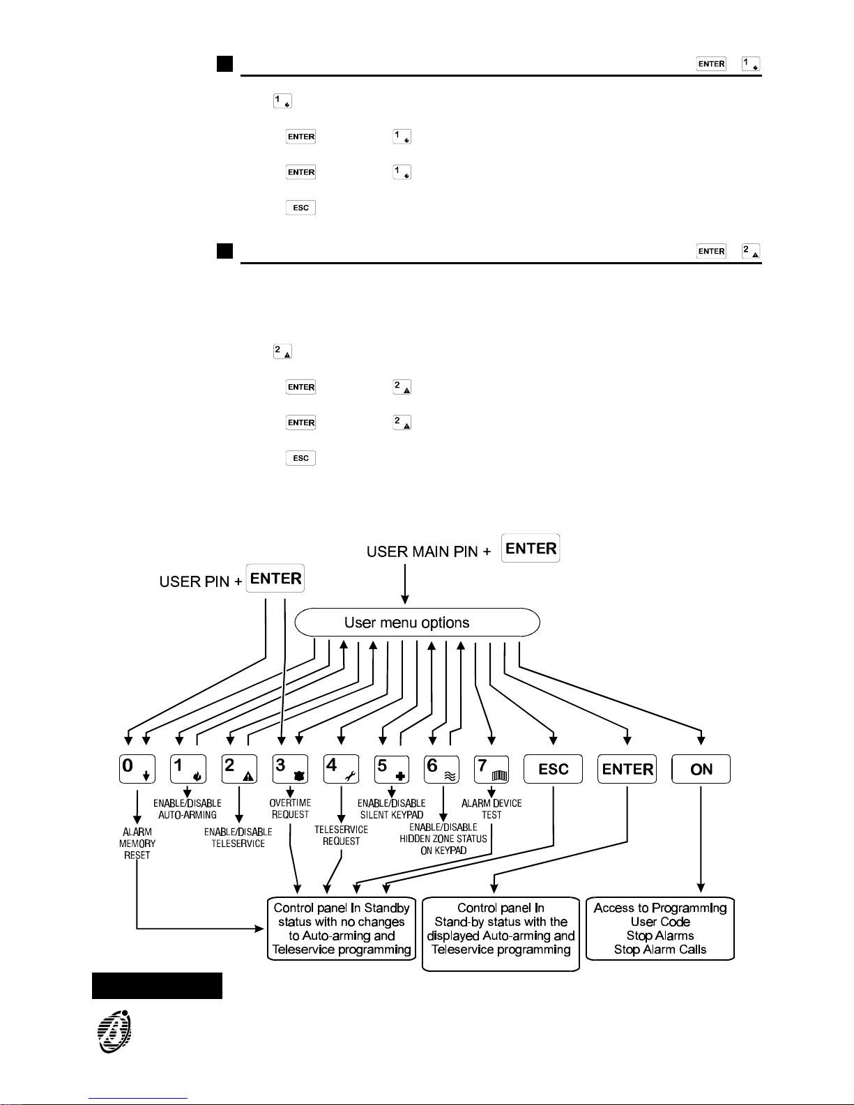
Enable / Disable auto arming
<Code PIN>+ +
Key toggles auto arming
1.
Press when key is ON to enable auto arming.
2.
Press when key is OFF to disable auto arming.
3.
Press to quit without changing the current status.
Enable / Disable Teleservice
<Code PIN>+ +
The Installer can call the Control panel to activate Teleservice, only after
the User has enabled the Teleservice option (the control panel will be able
to receive incoming Teleservice calls).
Key toggles Teleservice.
1.
Press when key is ON to enable Teleservice.
2.
Press when key is OFF to disable Teleservice.
3.
Press to quit without changing.
+
The Teleservice enabled / disabled status is also shown on the PRG LED
on the keypad.
Figure 4 User Options via keypad
Overtime requests are possible only when auto arming is enabled
CONTROL FROM KEYPAD 19
Page 20
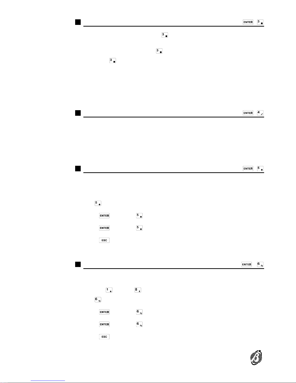
Overtime Request
<Code PIN>+ +
If auto arming is disabled key will be OFF, and therefore, if pressed
will have no effect.
If auto arming is enabled key will flash slowly.
Press key to activate the Overtime request, and delay the programmed
auto arming time by 30 minutes
+
The Overtime Requests will affect the partitions (established during programming) controlled by the Code PIN.
When the Overtime Request on any partition goes beyond midnight (00.00
on the Timer), auto arming (if enabled) will occur at midnight.
Teleservice Request
<Code PIN>+ +
The User can make a Teleservice Request call (remote intervention via
telephone) to the programmed Installer telephone number, only when the
Installer is equipped and ready for Teleservice.
The Installer Telephone number will be dialled shortly after the long-high
tone beep which confirms acceptance of the Teleservice Request.
Enable / Disable Silent keypad
<Code PIN>+ +
The Silent option can be enabled / disabled on each keypad. When this
option is enabled the keypad will not emit any sound during the elapsing
Entry / Exit delay.
Key toggles the Silent option
1.
Press when key is ON to enable the Silent option on the keypad.
2.
Press when key is OFF to disable the Silent option on the keypad.
3.
Press to quit without changing the current status.
Each keypad must be programmed separately.
Enable / Disable Hidden zone status on keypad
<Code PIN>+ +
The "Hidden" option can be enabled / disabled on each keypad. When this
option is enabled the current status of the zones will not be shown on num-
ber keys through
Key toggles the Hidden option
1.
Press when key is ON to enable the "Hidden" option.
2.
Press when key is OFF to disable the "Hidden" option.
3.
Press to quit without changing the current status.
Each keypad should be programmed separately.
20 Security System Control Panels Omnia8/Omnia4
Page 21

Alarm Device Test
<Code PIN>+ +
Use this option to test the alarm devices connected to the Alarm Output
(e.g. Outdoor and Indoor Sirens).
To test Alarm Devices:
1. Enter a Main User Code Code PIN on any keypad.
2.
Press .
3.
Press .
The Alarm Output will be activated for approximately 2 seconds the User
menu will be quitted.
+
Not all the Alarm Devices will stop when the Alarm Output returns to
standby status (e.g. telephone dialler), and therefore, must be stopped by
other means (ask the Installer for details).
User Code PIN Programming
<Code PIN>+ +
Main User Code PINs can access the User Code PIN Programming
phase. The Installer cannot access this phase.
+
Access to the User Code PIN programming phase will generate the Stop
alarm event, and the Stop all Calls procedures (refer to the following paragraphs).
Change User PIN A Main User can change the assigned PIN, however, a Main User cannot
change the PIN of another Main User and cannot program User Code PINs
which are enabled on partitions that the Main User in question cannot control.
To access the User Code PIN Programming phase in order to change
the default User Code PINs (1 through 23), or to change a programmed
Code PIN:
1. Enter Main User Code PIN.
2.
Press .
3.
Press .
4. Enter the Identifier number of the Code PIN to be changed (refer to the No.
Column of the table on page 27).
5.
Press .
6. Enter the new PIN (4 through 6 digits).
7.
Press to confirm and step to step 4.
8.
Press to quit programming phase. The PRG LED will stop flashing.
The Installer can program the Code Type as follows: 1= DISABLED,
2=MAIN USER, 3=USER, 4=DURESS, or 5=PATROL.
CONTROL FROM KEYPAD 21
Page 22
ATTENTION Please remember that Code PINs cannot be traced,
therefore, it is advisable to have a written record. The table on page 27
should be used for this purpose (the Code PIN table must be kept in a
safe place). Factory default can be restored by the Installer if required.
Stop alarm
<Code PIN>+ +
Refer to the note in the User Code PIN Programming paragraph.
Alarm status will activate the alarm signalling devices, and the Digital Com-
municator and Dialler.
To stop an alarm procedure:
Disarm the partition in alarm status
To stop a tamper alarm:
1. Disarm the partition in alarm status.
2. Reset Alarm Memory (refer to "Reset Alarm Memory" paragraph).
To stop a persistent alarm (e.g. generated by a sensor):
1. Enter Code PIN.
2.
Press .
3.
Press .
All the alarm signalling devices on the partition in question will be forced
into standby status. New alarms on the partition in question will be ignored.
This status will be signalled by slow flashing on the PRG LED.
This status will be held until is pressed.
+
Only Main User Code PINs can stop alarms generated by system tamper.
Stop all Calls
<Code PIN>+ +
Refer to the note in the User Code PIN Programming paragraph.
The programmed alarm calls (Event messages) will be sent to the Central
Station when the assigned Event occurs.
To Stop an outgoing alarm call, and clear the call queue:
1. Enter a Main User Code PIN.
2.
Press .
3.
Press .
The PRG LED will start flashing slowly to signal access.
This status will be held until is pressed.
No calls will be sent while the control panel is in this status, even if other
call generating events occur.
22 Security System Control Panels Omnia8/Omnia4
Page 23
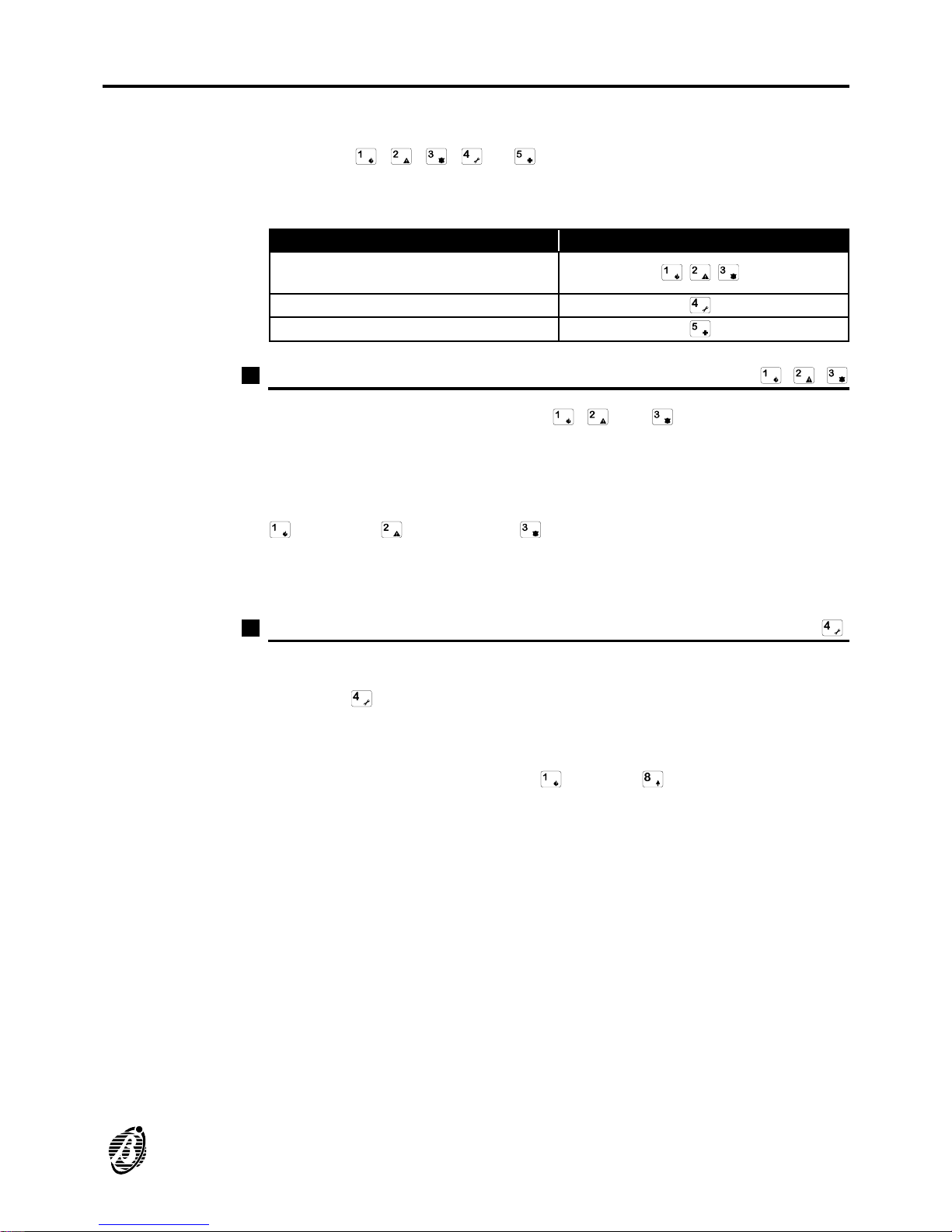
Superkeys
Each Superkey controls a specific command. Superkeys commands do not
require Code PINs.
Press key , , , or for approximately 4 seconds. The selected key will take on Superkey status, and the assigned command will be
activated.
COMMAND SUPERKEY
Activate Instant alarm call on the
Digital Communicator and Dialler
,
View alarm memory
,
Trouble Viewing mode
Instant alarm call
Superkeys , ,
Events corresponding to superkeys , and must be programmed
by the installer. The 3 alarm types (Fire, Danger and Police Request) can
each be assigned to a specific Event Call. The required Event call can be
activated from the keypad by pressing the corresponding key for approximately 4 seconds. The icon on the key identifies the alarm type.
Fire alarm Danger alarm Police
A long high-tone beep will confirm command acceptance. The Digital Communicator and Dialler will be activated shortly after.
View Alarm Memory
Superkey
To view the alarm memory:
Press key for approximately 4 seconds.
A long high-tone beep will confirm command acceptance.
Any alarm and / or tamper events which may occur after Reset Alarm
Memory will be shown on keys through (corresponding to the
zones), as follows:
----ON indicates alarm memory on the corresponding zone
----Slow flashing indicates tamper memory on the corresponding zone
----Fast flashing indicates alarm and tamper memory on the corresponding
zone
CONTROL FROM KEYPAD 23
Page 24
Trouble Viewing mode
Superkey
To view:
Press key for approximately 4 seconds
A long high-tone beep will acknowledge acceptance of the command.
This status will be signalled by slow flashing on the Trouble LED.
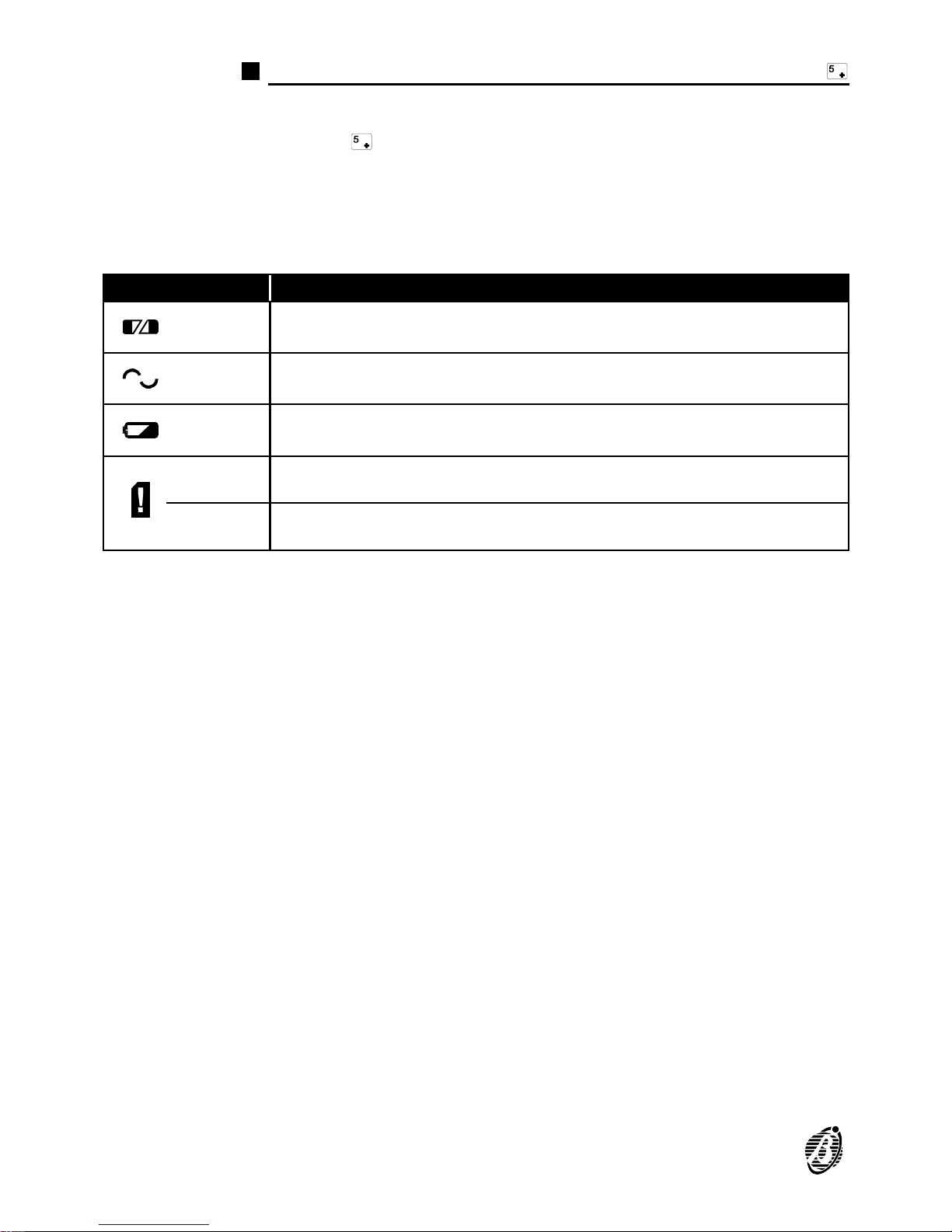
Keys 1-4-7-A (on the left side of the keypad) will indicate trouble status, as
per the following table:
KEYS STATUS
Key 1
off:
ON:
Sensor power protection fuse intact
sensor power protection fuse blown
Key 4
off:
ON:
Main Unit powered by mains
Mains failure: Main Unit powered by battery
Key 7
off:
ON:
Battery charged
Low battery or battery trouble
Key A
off:
ON:
Communication bus OK
Communication bus trouble
Key 0
off:
ON:
Telephone line OK
Telephone line trouble
Press any key to quit the Trouble Viewing Mode.
The control panel will quit this phase automatically ----if no key is pressed
within 20 seconds of access.
+
Check the trouble status each time the Trouble LED goes ON, and if necessary call your service dealer.
24 Security System Control Panels Omnia8/Omnia4
Page 25
APPENDIX
Zones insert
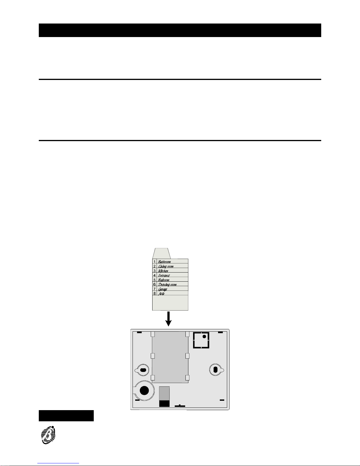
The Zones insert, inside the package, should be filled in and kept in the
holder on the keypad backplate (see figure 5). In this way, the zones insert
will always be on hand when identification of a zone is necessary i.e. when
a key on the keypad goes ON or starts flashing.
Programming sheets
The Installer should fill in the programming sheets in the following pages.
The User should refer to the sheets when information regarding the security system is required.
Figure 5 Zones insert and holder on keypad backplate
APPENDIX 25
Page 26

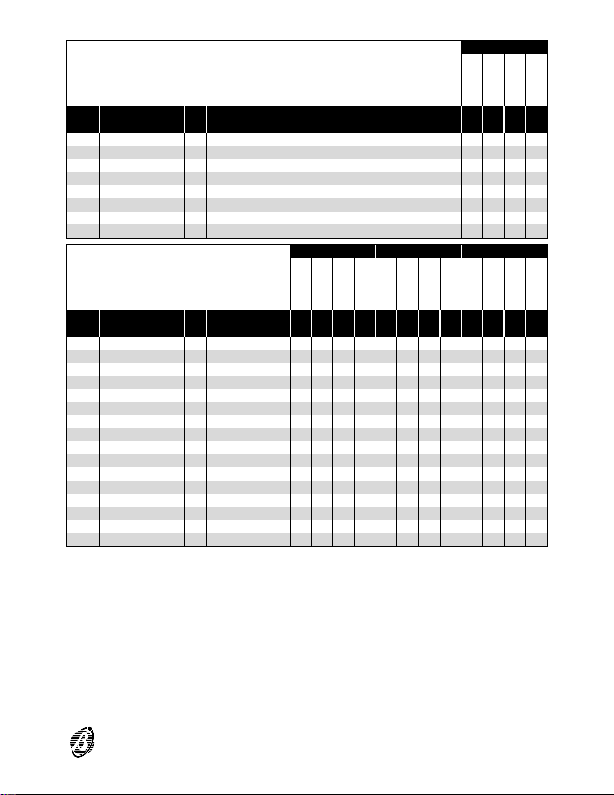
Partitions Type A Arming Type B Arming
Use this row for the Partition
Descriptions
No. Description Type PIN 1 2 3 4 1 2 3 4 1 2 3 4
1
2
3
4
5
6
7
8
9
10
11
12
13
14
15
16
17
18
19
20
21
22
23
User Code Factory Default Programming
1 Code 001 Main User 0001 Yes Yes Yes Yes A A A A A A A A
2 Code 002 User 0002 Yes Yes Yes Yes A A A A A A A A
3 Code 003 Duress 0003 Yes Yes Yes Yes A A A A A A A A
4 Code 004 Patrol 0004 Yes Yes Yes Yes A A A A A A A A
No. This is the Code identifier Number.
Description This is the Code description.
Type This is the Code Type.
PIN This is the Code PIN Number. The PIN allows access to the enabled op-
tions of the Code in question.
Partitions This is the enabled partitions of the Code in question.
Type A Arming These are the partitions that will be armed (A), and those that will be dis-
armed (D) when the Code is used for Type A Arming.
Type B Arming These are the partitions that will be armed (A), and those that will be dis-
armed (D) when the Code is used for Type B Arming.
26 Security System Control Panels Omnia8/Omnia4
Page 27
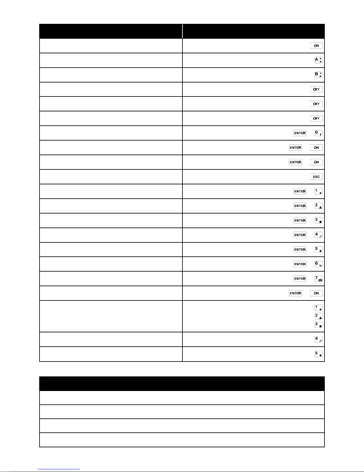
Partitions
Use this row for the Partition Descriptions
Add.
Keypads in
configuration
No. Description 1 2 3 4
01 1
02 2
03 3
04 4
05 5
06 6
07 7
08 8
Red Amber Green
Use this row for the Partition
Descriptions
Add.
Key readers in
configuration
No. Description 1 2 3 4 1 2 3 4 1 2 3 4
01 1
02 2
03 3
04 4
05 5
06 6
07 7
08 8
09 9
10 10
11 11
12 12
13 13
14 14
15 15
16 16
Add. This is the Device Address (Keypad or Key reader).
No. This is the identifier number (Keypad or Key reader).
Partitions These are the partitions the keypad can control.
Red These are the partitions that will be armed when the Red LED is ON and
the digital key is extracted.
Amber These are the partitions that will be Armed (A) and Disarmed (D) when the
Amber LED on the key reader is ON, and the digital key is extracted.
Green These are the partitions that will be Armed (A) and Disarmed (D) when the
Green LED on the key reader is ON, and the digital key is extracted.
APPENDIX 27
Page 28
OPTION KEYPAD
Global arming
Main User or User code +
Type A arming
Main User code or User code +
Type B arming
Main User code or User code +
Disarm
Main User code or User code +
Temporary Disarm (Patrol)
Patrol code +
Disarm under Duress
Duress code +
Reset Alarm Memory
Main User or User code + +
Stop alarm
Main User code + +
Stop Calls
Main User code + +
Bypass zones
Main User code +
Enable / Disable auto arming
Main User code + +
Enable / Disable Teleservice Answer
Main User code + +
Overtime request
Main User or User code+ +
Send Teleservice Call
Main User code + +
Enable / Disable Silent keypad
Main User code + +
Enable / Disable Hidden zone status on keypad
Main User code + +
Alarm Device Test
Main User code + +
User Code PINs Programming
Main User code + +
Activate Instant Alarm on communicator
Superkey
Superkey
Superkey
View alarm memory
Superkey
Trouble Viewing mode
Superkey
FOR YOUR SERVICE DEALER PLEASE CONTACT:
Installer Company:
Telephone:
Address:
Contact Person:
 Loading...