


VRA 065
BENSON VRA 065, VRA110, VRA140, VRA170, VRA220 Installation And Service Manual
...
Types VRA 065/090/110/140/170/220/285
Types VRC 065/090/110/140/170
Types VRE 090/110//170/220
VARIANTE RANGE
INSTALLATION AND SERVICE MANUAL
Issue 2 0ctober 2003
1
BENSON GAS UNIT HEATERS
49/AU/2840
0049

The Instructions contained in this manual apply to Variante gas fired models only.
These models are suitable for roof suspension, indoor installation only.
VRA VRC models are suitable for both horizontal and vertical room sealed flue terminals
IMPORTANT :
Variante heaters must be installed in sufficiently ventilated premises
In garage applications the must be mounted at a minimum height of 1.8 meters to the bottom of the
heater from floor level
It is a requirement that only suitably qualified and competent personnel may install and
commission the heater
The heater should be installed so as to comply with all the relevant standards and guide lines as
well as meeting all national and local regulations and insurance criteria
The Benson Variante range of warm air heaters detailed herewith are manufactured for Benson Heating
within the parameters of ISO 9002.
The Benson Variante range has been independently tested and assessed, and has been found to meet
the Essential Requirement of the following European Directives:
Gas appliance Directive (90/396/EEC)
Machinery Directive (89/392/EEC)
Low Voltage Directive (73/23/EEC and 93/68/EEC)
Electromagnetic Compatibility Directive (98/336/EEC and 91/31/EEC)
Product Liability Directive (65/374/EEC)
Contents
Section INDEX Pages
1 GENERAL RECOMENDATIONS 2-3
2 TECHNICAL SPECIFICATION 4
2-1 VRA Data 4
2-2 VRC Data 5
2-3 VRE Data 6
3 INSTALLATION 7
3-1 Wall mounting dimensions VRA 065 -170 VRC065 -110 7
3-2 Girder mounting dimensions VRA 065 -170 VRC 065 -110 7
3-3 Wall mounting dimensions VRA 220 - 285 8
4 ASSEMBLY INSTRUCTIONS FOR VRC RANGE 8
5 WIRING DIAGRAMS 9
5-1 Electrical diagram VRA 9
5-2 Remote connections VRA CP 2 10
5-3 Electrical diagram VRA Remote connections CP4 10
6 FLUE INSTALLATION 11
6-1 Recommended horizontal concentric flue for VRA 065 to 110 11
6-2 Recommended horizontal concentric flue for VRA 140 to 285 11
6-3 Recommended Vertical concentric flue for VRA 065 to 110 12
6-4 Recommended Vertical concentric flue for VRA 140 to 285 12
6-5 Recommended vertical flue assembly for VRA 065 to 110 13
6-6 Recommended vertical flue assembly for VRA 140 to 285 13
6-7 Accessories for flue for models VRA 065 to 110 14
6-8 Accessories for flue for models VRA 140 to 285 14
7 VRE RANGE DATA 15
7-1 Fixing height dimensions VRE Range 15
7-2 Recommended vertical flue connections VRE range 15
8 GAS 16
8-1 Gas conversion 16
8-2 Gas supply 17
9 SERVICE 17
9-1 Heater Controls VRA 18
10 MAINTENANCE 19
11 END USER RECOMMENDATIONS 19
12 FAULT FINDING 20
1-GENERAL RECOMMENDATIONS

The manufacturer has taken reasonable and practical steps to ensure that Benson Variante Ra nge of Heaters
are safe and without risk when properly used. These heaters should therefore only be used in the manner and
purpose for which they were intended, and in accordance with the recommendations detailed herewith.
The heaters have been designed, manufactured, assembled, inspected, and tested, with safety and quality in
mind, there are certain basic precautions which the installer and user should be awa re of, and they are strongly
advised to read the appropriate sections of the information pack accompanying the heater, prior to installation or
use.
Benson Heating supports all new products being supplied to their customers with a comprehensive information
pack; this clearly defines mandatory instructions for the safe installation, use, and maintenance, of the appliance
(s).
Where proprietary items are incorporated into Benson Heating products, detailed information and instructions
are also provided as part of the information pack.
It is the responsibility of the installer, owner, user, or hirer, of such products supplied by Benson Heating, to ensure that they are familiar with the appropriate information/manuals, supplied by the manufacturer, and that they
are suitably aware of the purpose of the manuals and the safety instructions. In addition, operators must be
suitably trained in the use of the appliance so as to ensure its continued safe and efficient use.
Benson Heating has a commitment to continuous improvement, and therefore reserves the right to amend or
change the specification of the Variante Heater range subject to agreement from The Notified Body.
The heater is supplied with a 2 year warranty on all parts.
The warranty commences from the date of dispatch from the manufacturer, and is subject to the terms detailed
within the manufacturer 'conditions of business'.
The warranty may be invalidated if :
a) The warranty registration/commissioning card has not been completed and returned to the manufa cturer
b) The installation is not in accordance with the general requirements of this manual
c) The flue arrangement and air supply for the heater are not in accordance with the manufacturers
recommendations, codes of practice, or similar standards
d) Air flow through the heater is not in accordance with the manufacturers technical specifications
e) Internal wiring on the heater has been tampered with or unauthorised service/repairs undertaken
f) The main electrical supply input to the heater has been interrupted during the heating mode
g) The heater has been subject to and affected by the ingress of water in any form
h) The heater is not operated at the rating(s) laid down in the manufacturers technical specifications
i) The heater has not been operated or used within the normal scope of its intended application
j) The manufacturer's recommended minimum service requirements have not been complied with
All warranty claims must contain the following information to enable processing to take place;
(1) Heater model , (2) Heater serial number (3) Order reference/date of order, together with full installation details (name and address) (4) Details or symptoms of fault (5) Installers name and address.
Faulty parts must be returned to the manufacturer Spares Department, the address of which is provided on the
rear cover of this manual. Any such parts will undergo inspection to verify the claim. Replacement parts supplied
prior to this may be charged, and a credit supplied upon subsequent validation of the warranty claim. Consumable items are specifically not included within the scope of the warranty.
Notification is required immediately a fault is suspected. The manufacturer will not accept responsibility for any
additional damage that has been caused, expense incurred, or consequential loss resulting from any failure of
the heater(s).
Any reference made to Laws, Standards, Directives , Codes of Practice or other recommendations governing the application
and installation of heating appliances and which may be referred to in Brochures, Specifi cations, Quotations, and Installation,
Operation and Maintenance manuals is done so for information and guidance purposes only and should only be considered
valid at the time of the publication. Manufacturer cannot be held responsible from any matters arising from the revision to or
introduction of new Laws, Standards, Directives, Codes of Practice or other recommendations.

TYPES VRA065 VRA090 VRA110 VRA140 VRA170 VRA220 VRA285
Heat Input kW 21 28 35 45 55 71 92
Heat Output kW 19,5 25,5 31,5 40,5 50 64,4 84
Efficiency % 92.8 91.1 90.0 90.0 91.0 90.7 91.3
No Fans 1 1 1 1 1 1 2
Airflow @ 15 °C
Airflow @ 50 °C
m3/h
1 450
1 625
2 050
2 250
2 900
3 250
4 000
4 400
4 900
5 400
5 800
6 400
8 000
8 800
Delta T °C 40 36 32 30 30 32 32
Axial fan throw m 12 16 23 26 28 30 30
Gas rate @ 15°C
Natural G20
Propane G31
20 mbar
37 mbar
2.22 m
3
/ h
1.64 kg/h
2.96 m
3
/ h
2.18 kg/h
3.70 m
3
/ h
2.73 kg/h
4.76 m
3
/ h
3.51 kg/h
5.82 m
3
/ h
4.30 kg/h
7.40 m
3
/ h
5.46 kg/h
10.0 m
3
/ h
7.40 kg/h
Flue diameter mm
80 /125 80/125
100 130 130 130
Comb air diameter mm 100 130 130 130
Electrical Supply V 230 volts 1ph 50Hz
Running Current A 1.3 1.3 1.4 1.5 2.2 2.5 3.2
Weight kg 82 82 90 105 127 145 185
Sound level @ 5M
dBa 39 40 41 46 51 51 49
80/125
Fan Speed 900 900 900 900 1400 1400 900
Tr/m
Technical Data VRA
Dimensional Data VRA
Model VRA
Models VRA are Room Sealed
Axial fan with vertical and horizontal
louvres as standard and are
unsuitable for ducted systems
VRA
A B C
Ø
Flue
Ø
Air Ø Gas
065
1040 800 460 80 / 125 1/2
090
1040 820 460 80 / 125 1/2
110
1040 820 510 1/2
140
1040 820 570 100 100 1/2
170
1040 840 700 130 130 1/2
220
1120 840 825 130 130 3/4
285
1120 840 1075 130 130 3/4
80 / 125
2–1 TECHNICAL SPECIFICATIONS
Connections 140/170/220/285
Flue-
Gas
Air
Connections 65/90/110
Flue
Gas

2-2Technical Data VRC
Dimensional Data :
TYPES VRC065 VRC090 VRC110 VRC140 VRC170
Heat Input kW 21 28 35 45 55
Heat Output kW 19,5 25,5 31,5 40,5 50
Efficiency % 92.8 91.1 90.0 90.0 90.7
Fan speed Tr/m 1 400 1 400 1 400 1 400 1 400
Airflow @ 15 °C
Airflow @ 50 °C
m3/h
1 450
1 625
2 050
2 250
2 900
3 250
4 000
4 400
4 900
5 400
Delta T °C 40 36 32 30 30
Available outlet pressure mm CE 10 10 10 10 10
Gas rate @ 15°C
Natural G20
Propane G31
20 mbar
37 mbar
2.22 m3/ h
1.64 kg/h
2.96 m3/ h
2.18 kg/h
3.70 m3/ h
2.73 kg/h
4.76 m3/ h
3.51 kg/h
5.82 m3/ h
4.30 kg/h
Flue diameter mm
80 / 125 80 / 125 80 / 125
100 130
Combustion air diameter mm 100 130
Electrical supply 230 volts / 1ph / 50Hz
Running current A 3.8 4.0 4.0 5.5 6.0
Weight kg 97 97 105 120 147
Model VRC
Models in the VRC range are room sealed with
Centrifugal Fan suitable for ducted systems
(Vertical and Horizontal louvres optional)
VRC
A C D L Ø F
Ø
Air Ø Gas
065
1040 460 1160 360 80 / 125 1/2
090
1040 460 1160 360 80 / 125 1/2
110
1040 510 1160 410 80 / 125 1/2
140
1040 570 1260 470 100 100 1/2
170
1040 700 1260 600 130 130 1/2
Connections 65/90/110
Connections 140/170
Flue
Flue
Gas
Gas

Dimensional Data
2-3 Technical Data VRE
TYPES
VRE090 VRE110 VRE170 VRE220
Heat Input kW
28 35 55 71
Heat Output kW
25,5 31,5 50 64,4
Efficiency %
91.1 90.0 91.0 90.7
No of fans
1 1 1 1
Motor speed Tr/m
900 900 1 400 1 400
Gas consumption @ 15 °C
Gas consumption @ 50 °C
m3/h
2 050
2 250
2 900
3 250
4 900
5 400
5 800
6 400
Delta T° °C
36 32 30 32
Axial fan throw m
Installation height mini/maxi m
4 / 5 4 / 6 5 / 10 6 / 12
Gas rate @ 15°C
Natural G20
Propane G31
20 mbar
37 mbar
2.96 m3/h
2.18 kg/h
3.70 m3/ h
2.73 kg/h
5.82 m3/ h
4.30 kg/h
7.40 m3/ h
5.46 kg/h
Flue Diameter mm
80 / 125 80 / 125
130 130
Combustion air diameter mm
130 130
Electrical supply
230 volts / 1ph / 50Hz
Running current A
1.3 1.8 2.6 3.7
Weight kg
82 90 127 145
Sound level @ 5m
dBa
40 41 51 51
25
30 40 40
Model VRE
Models in the VRE range are room sealed and
have an Axial fan and both horizontal and vertical
double deflectors to assist with destratification
VRE
A B C
Ø
Flue
Ø
Air
Ø
Gas
090
1040 820 460 80/125 1/2
110
1040 820 510 1/2
170
1040 840 700 130 130 1/2
220
1120 840 825 130 130 3/4
80/125
Connections 170/220 Connections 90/110
3– INSTALLATION OF HEATERS
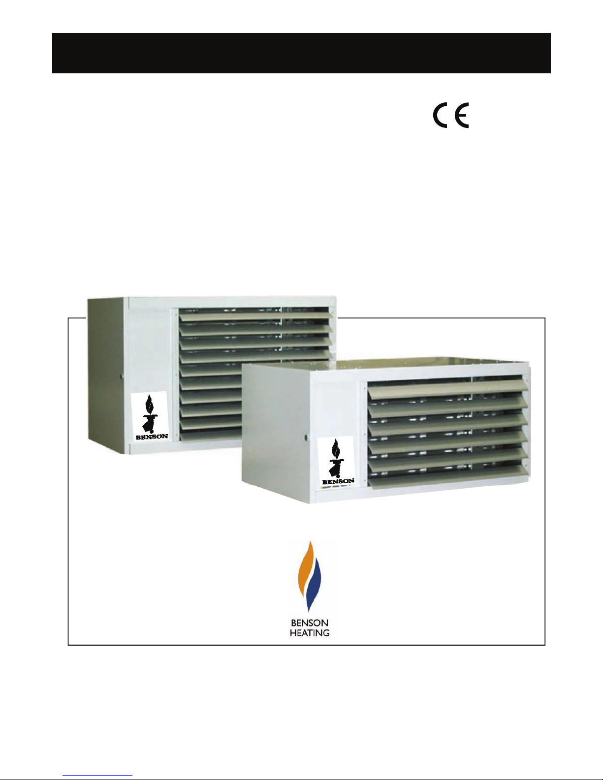
3-1 Wall mounting installation for VRA 065 to 285 and VRC 065 to 110
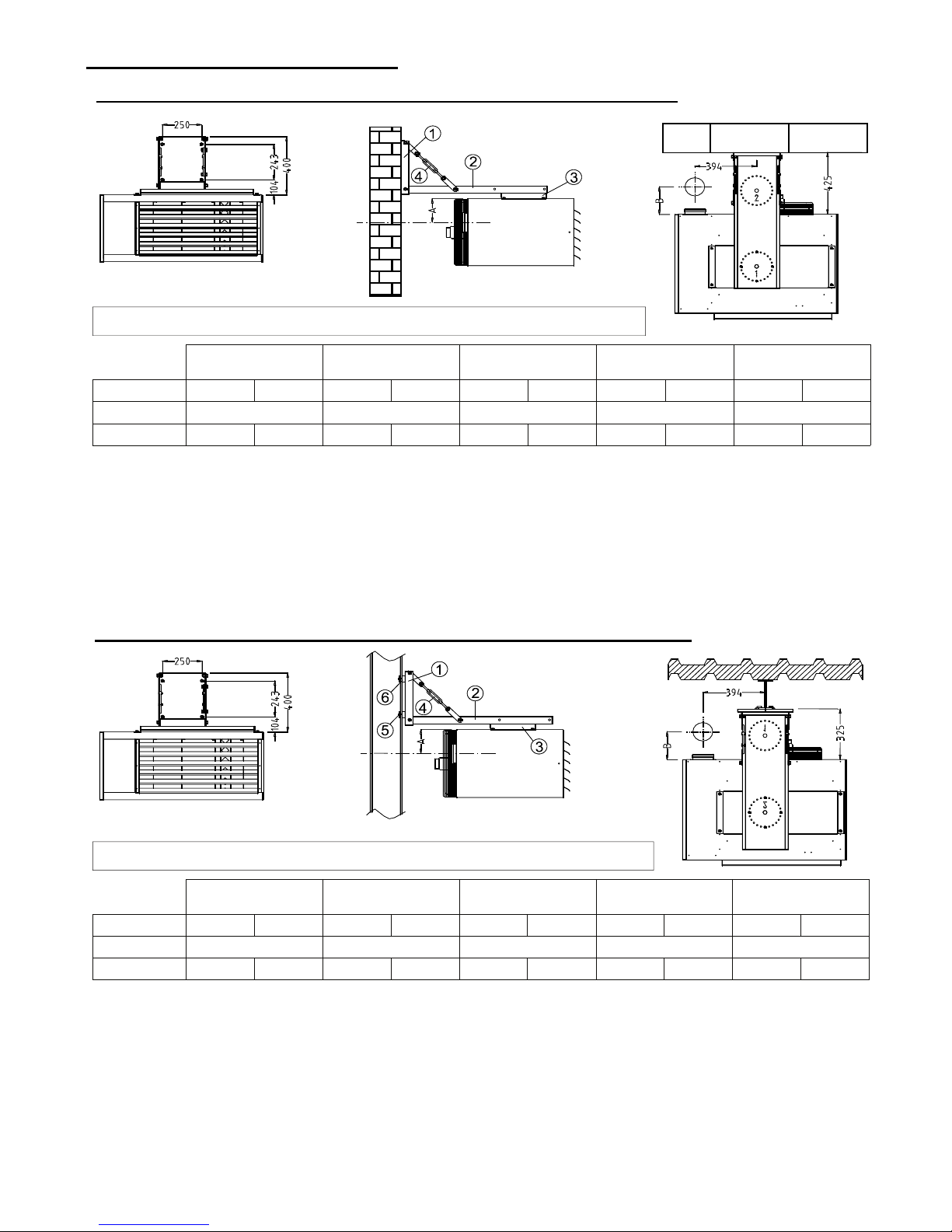
3-2 Girder mounting installation for VRA 065 to 285 and VRC 065 to 110
1- Mount plate (1) with suitable masonry bolts to the wall at the required height and level.
2- Fit plate (2) to plate (1) ensuring the plate is the correct way round see drawing below
NOTE there is one fitting for walls and one for girder support .
3- Connect the two turnbuckles (4) to plate (1) and adjust until level.
4- Fit plate (3) to top of heater
5- Lift heater in place and secure plate (3) to plate (2) adjust to required position
1- Fix the plate (1) to the girder using the adaptors (6) and bolts (5).
2- Fit plate (2) to plate (1) ensuring that it is the correct way round see drawing.
3- Connect the two turnbuckles (4) to plate (1) and (2) and adjust until level.
4- Fit plate (3) to top of heater
5- Lift heater in place and secure plate (3) to plate (2) adjust to required position
Warning ensure the girder is suitable to support heater weight
Warning ensure the wall is suitable to support heater weight
Flue
Connection
VRA VRC 065 VRA VRC 090 VRA VRC 110 VRA 140 VRA 170
Dimensions B22 C32 B22 C32 B22 C32 B22 C32 B22 C32
A (mm) 160 160 185 200
B (mm) 115 125 115 125 115 125 125 190 135 205
250
Flue
Connection
VRA VRC 065 VRAVRC 090 VRA VRC 110 VRA 140 VRA 170
Dimensions B22 C32 B22 C32 B22 C32 B22 C32 B22 C32
A (mm) 160 160 185 200
B (mm) 115 125 115 125 115 125 125 190 135 205
250
 Loading...