


BENSH
Use Guid
e
®
890048-01-00
9,I
c.

M2L 3000 Series VFD
2

which can cause personal injury or death
Important Reader Notice
Congratulations on the purchase of your new Benshaw M2L 3000 Medium Voltage Variable Frequency Drive, hereafter referred in this document as the “M2L 3000” or the “drive”.
This User Guide may not cover all of the applications for the M2L 3000, nor can it provide information on every possible contingency concerning installation, programming, operation, or maintenance specific to M2L 3000 VFD systems.
The content of this manual will not modify any prior agreement, commitment or relationship between the customer and Benshaw. The sales contract contains the entire obligation of Benshaw. The warranty enclosed within the contract between the
parties is the only warranty that Benshaw will recognize, and any statements contained herein do not create new warranties or
modify the existing warranty in any way.
Any electrical or mechanical modifications to Benshaw products without prior written consent of Benshaw will void all warranties, and may also void any safety certifications; unauthorized modifications may also result in product damage, operation malfunctions, or personal injury.
Incorrect handling of the drive may result in an unexpected fault or equipment damage. For best results when operating the
M2L 3000 drive, carefully read this manual and all warning labels attached to the system before installation and operation.
Keep this manual on hand for reference.
Do not attempt to install, operate, maintain or inspect the drive until you have thoroughly read this manual and related documents carefully, and can use the equipment correctly.
Do not use the drive until you have a full knowledge of the equipment, safety procedures and instructions.
Symbols
This User Guide classifies safety, protection, and general information levels as Warning,
Caution, and Note.
WARNING: Warns of a physical safety condition or Electrical Hazard
CAUTION: Warns of situations in which equipment damage may occur
NOTE: Indicates a specific piece of information applicable to the use or operation of the drive.
3

M2L 3000 Series VFD
WARNINGS HAZARDS OF ELECTRIC SHOCK, EXPLOSION, OR ARC FLASH.
Failure to follow the instructions below may result in serious injury or death.
DANGER. This equipment does not provide isolation. Separate isolating
means required. Isolation devices can take several forms with the most
simple being an appropriately sized disconnect switch and contactor pair
utilizing the Inverter ‘Shunt Trip’ controls, or an appropriately sized and
protected vacuum circuit breaker also capable of remote operation from
the inverter ‘Shunt Trip’ controls. See page 32 for more information.
WARNING: At any time the system is energized with Medium Voltage
power, apply appropriate personal protective equipment (PPE) and follow
safe electrical work practices when operating or working near the system.
See NFPA 70E.
Cabinet Fault Limit: <10kA @ 10 Cycles
Min Arc Boundary: 40 Inches
Recommended Min. PPE: #1 at > 40 inches
WARNING: Branch circuit protection is required for the equipment. See
page 32 for more information.
WARNING: Only qualified personnel familiar with the use and hazards of
medium voltage equipment are to perform work described in this set of
instructions.
WARNING: Before performing visual inspections, tests, or maintenance
on the equipment, disconnect all sources of electric power. Assume that
circuits are live until completely de-energized, tested, and tagged.
Pay particular attention to the design of the power system. Consider all
sources of power, including the possibility of backfeeding.
Use a properly rated voltage sensing device to confirm that the power is
fully removed.
WARNING: Always perform applicable lock-out/tag-out procedures (either general or site-specific) before performing any maintenance or troubleshooting on the system.
WARNING: To avoid potentially lethal levels of both AC and DC voltages,
do not remove the cover to access the MV Input/Output section of the Inverter while the Inverter is energized.
WARNING: Equipment may be supplied from multiple power sources.
Refer to drawings for more information.
4

wire
CAUTIONS
WARNING: Potentially hazardous voltages will remain in the cells until
the capacitors are able to de-energize. Wait at least 30 minutes after
main power is removed for the stored voltages to dissipate if removing
the Inverter Cell or Input/Output section covers. Do not rely solely on the
voltage values displayed on the HMI Meter Values screen to determine if
it is safe to remove the covers on the Inverter Cell and Input/Output sections.
WARNING: The Control section contains 240V control power when active. The Control section does not contain medium voltage levels supplied from the mains, and can be carefully accessed by qualified personnel while medium voltage from the AC mains is applied to the system.
WARNING: Replace all devices, doors, and covers before applying
power to this equipment.
WARNING: Do not attempt to lift and position either the Converter or Inverter with a crane without the proper equipment or experience performing this type of operation. Benshaw can arrange the services of professional firms who routinely rig and lift heavy equipment.
CAUTION: Special care must be taken with covers that have a ground
attached to the inside that ties them to ground potential. It is important that the connection integrity of this wire be maintained to avoid
compromising the immunity of the Inverter to Electromagnetic Interference (EMI) and safety.
CAUTION: Always be aware of electrostatic discharge (ESD) when working near or touching components inside the drive. Handling of components sensitive to ESD should be done by qualified personnel only, familiar with ESD mitigation techniques.
CAUTION: Parameter settings and adjustments should be performed by
those familiar with VFD and motor operation characteristics. It is not recommended for users unfamiliar with these concepts.
5

M2L 3000 Series VFD
6

Table of Contents
IMPORTANT READER NOTICE ....................................................................................................................................................................... 3
Symbols ............................................................................................................................................................................................. 3
1 - Introduction .............................................................................................................................................................................. 11
DOCUMENTATION ................................................................................................................................................................................... 11
ON-LINE DOCUMENTATION....................................................................................................................................................................... 11
REPLACEMENT PARTS ............................................................................................................................................................................... 11
PUBLICATION HISTORY ............................................................................................................................................................................. 11
WARRANTY ............................................................................................................................................................................................ 11
CONTACTING BENSHAW ........................................................................................................................................................................... 11
SYSTEM DESIGN FEATURES ........................................................................................................................................................................ 12
PART NUMBER DEFINITIONS ...................................................................................................................................................................... 14
2 - Specifications ............................................................................................................................................................................ 17
GENERAL SPECIFICATIONS ......................................................................................................................................................................... 17
CONVERTER INPUT: ................................................................................................................................................................................. 17
ENVIRONMENTAL .................................................................................................................................................................................... 17
CONDITIONS ........................................................................................................................................................................................... 17
COOLING SYSTEM .................................................................................................................................................................................... 18
CONSTRUCTION ...................................................................................................................................................................................... 18
LIFTING PROVISIONS ................................................................................................................................................................................ 18
MINIMUM CLEARANCE ............................................................................................................................................................................. 18
ELECTRICAL RATINGS – 300A UNIT ............................................................................................................................................................ 19
ELECTRICAL RATINGS – 260A UNIT ............................................................................................................................................................. 20
COMMON ELECTRICAL RATINGS – 260A AND 300A UNITS ............................................................................................................................. 21
3 – Installation ............................................................................................................................................................................... 25
EMC INSTALLATION GUIDELINES ................................................................................................................................................................ 25
WIRING CONSIDERATIONS ........................................................................................................................................................................ 26
WIRING SCHEMATICS ............................................................................................................................................................................... 27
POWER WIRING ...................................................................................................................................................................................... 30
Input Line Requirements ................................................................................................................................................................. 30
Recommended Wire Gauges .......................................................................................................................................................... 30
Power Wire Connections ................................................................................................................................................................. 30
Compression Lugs ........................................................................................................................................................................... 30
Motor Lead Length ......................................................................................................................................................................... 31
Input Line Requirements ................................................................................................................................................................. 31
DC Lead Length Between Converter and Inverter ........................................................................................................................... 31
4 - Theory of Operation ................................................................................................................................................................. 33
M2L 3000 OVERVIEW ............................................................................................................................................................................ 33
CONVERTER............................................................................................................................................................................................ 34
INVERTER ............................................................................................................................................................................................... 36
IGBT Cell .......................................................................................................................................................................................... 36
5 - Operation ................................................................................................................................................................................. 41
INTRODUCTION ....................................................................................................................................................................................... 41
HMI OVERVIEW ..................................................................................................................................................................................... 42
STATUS INDICATORS................................................................................................................................................................................. 43
GETTING THE DRIVE READY ....................................................................................................................................................................... 45
OPERATING THE DRIVE ............................................................................................................................................................................. 46
7

M2L 3000 Series VFD
SELECTABLE VIEW OPTIONS ....................................................................................................................................................................... 47
6 - Parameter List .......................................................................................................................................................................... 57
DRIVE GROUP PARAMETER LIST ................................................................................................................................................................ 57
FUNCTION GROUP PARAMETER LIST ........................................................................................................................................................ 58
AFN (ADVANCED FUNCTION) GROUP PARAMETER LIST .................................................................................................................................. 61
I/O (INPUT/OUTPUT) GROUP PARAMETER LIST ............................................................................................................................................ 62
7 - Parameter Descriptions ............................................................................................................................................................ 73
DRIVE GROUP PARAMETERS ...................................................................................................................................................................... 73
FUNCTION GROUP PARAMETERS ................................................................................................................................................................ 77
AFN (ADVANCED FUNCTION) GROUP PARAMETERS ...................................................................................................................................... 83
I/O (INPUT/OUTPUT) GROUP PARAMETERS ................................................................................................................................................. 85
Digital Input Options ....................................................................................................................................................................... 85
Digital Output Options .................................................................................................................................................................... 87
Analog Input Options ...................................................................................................................................................................... 88
Low/High Parameters Process and Input Value ............................................................................................................................. 89
INVERTER ANALOG OUTPUT FUNCTIONS (I/O-72 THROUGH I/O-79) ............................................................................................................... 90
Analog Output Options ................................................................................................................................................................... 90
ANALOG OUTPUT PARAMETERS (I/O-80 THROUGH I/O-223) ........................................................................................................................ 92
Analog Output Type ........................................................................................................................................................................ 92
Process and Output Value Low/High .............................................................................................................................................. 92
CCI I/O PARAMETERS .............................................................................................................................................................................. 92
8 – Fault Conditions ....................................................................................................................................................................... 93
TABLE KEY ............................................................................................................................................................................................. 93
9 – Spare Parts ............................................................................................................................................................................. 125
SPARE PARTS LIST .................................................................................................................................................................................. 125
References ................................................................................................................................................................................... 127
Appendix A: Profibus-DP Modbus ................................................................................................................................................ 129
PROFIBUS-DP CONNECTION .................................................................................................................................................................... 129
PROFIBUS-DP INPUT DATA ..................................................................................................................................................................... 129
PROFIBUS-DP OUTPUT DATA .................................................................................................................................................................. 131
Glossary ....................................................................................................................................................................................... 133
COMPONENTS ...................................................................................................................................................................................... 133
18-Pulse Transformer ................................................................................................................................................................... 133
2-Position DC Landing Pad ............................................................................................................................................................ 133
3-Position AC Landing Pad ............................................................................................................................................................ 133
Card Cage ..................................................................................................................................................................................... 133
Computer Card .............................................................................................................................................................................. 133
Control Power Transformer .......................................................................................................................................................... 133
Converter ...................................................................................................................................................................................... 133
DC Bus Bar .................................................................................................................................................................................... 134
Disconnect Switch ......................................................................................................................................................................... 134
Dual Diode Module ....................................................................................................................................................................... 134
Ethernet Switch ............................................................................................................................................................................. 134
FOB ............................................................................................................................................................................................... 134
HMI ............................................................................................................................................................................................... 134
IGBT .............................................................................................................................................................................................. 134
8

Inner Air Filter ............................................................................................................................................................................... 134
Inverter ......................................................................................................................................................................................... 134
Inverter IO ..................................................................................................................................................................................... 134
Isolating CT ................................................................................................................................................................................... 135
Loop Power Supply Reactor .......................................................................................................................................................... 135
Loop Power Supply Transformer ................................................................................................................................................... 135
Main Contactor ............................................................................................................................................................................. 135
Main Contactor Relay ................................................................................................................................................................... 135
Modular Fan Assembly ................................................................................................................................................................. 135
Outer Air Filter .............................................................................................................................................................................. 135
Pole Filter ...................................................................................................................................................................................... 135
Power Cell ..................................................................................................................................................................................... 135
Power Cell Back Panel ................................................................................................................................................................... 136
Power FOB .................................................................................................................................................................................... 136
Precharge Board ........................................................................................................................................................................... 136
Precharge Board Cover ................................................................................................................................................................. 136
Precharge Resistor ........................................................................................................................................................................ 136
Rectifier Module ........................................................................................................................................................................... 136
SD Card ......................................................................................................................................................................................... 136
Shunt Trip Relay ............................................................................................................................................................................ 136
Snubber Assembly ......................................................................................................................................................................... 136
Surge Arrestor ............................................................................................................................................................................... 136
Thermal Switch Isolation Receiver Board ..................................................................................................................................... 137
Thermal Switch Isolation Transmitter Board ................................................................................................................................ 137
CONCEPTS............................................................................................................................................................................................ 137
Arm ............................................................................................................................................................................................... 137
ATL ................................................................................................................................................................................................ 137
Control Power ............................................................................................................................................................................... 137
Front End ...................................................................................................................................................................................... 137
Ground Fault ................................................................................................................................................................................. 137
Look Ahead ................................................................................................................................................................................... 138
Loop Power Supply........................................................................................................................................................................ 138
Low Voltage .................................................................................................................................................................................. 138
Medium Voltage ........................................................................................................................................................................... 138
Precharge ...................................................................................................................................................................................... 138
VFD ............................................................................................................................................................................................... 138
Revision History ........................................................................................................................................................................... 140
9

M2L 3000 Series VFD
10

1 - Introduction
A brief description of the application
1 - Introduction
Benshaw personnel are available to answer all inquiries including information regarding start-up services and on-site training. Refer to the following pages for contact information.
Documentation
On-Line Documentation
Replacement Parts
Publication History
Warranty
Contacting Benshaw
Benshaw can provide all customers with:
User Guides
Drawings / Wiring Diagrams
Drawings are available on CD / DVD or via e-mail by contacting Benshaw Customer
Service.
All MVVFD documentation is available on-line at www.benshaw.com.
Spare and replacement parts can be purchased from Benshaw Technical Support.
Refer to the inside back cover.
Benshaw provides a standard 5 Year factory warranty on the M2L 3000 MVVFD System.
Information about all Benshaw products and services is available on the internet at
www.benshaw.com, or by contacting Benshaw at one of the following offices:
Benshaw Corporate Headquarters Benshaw Canada
615 Alpha Drive
Pittsburgh, PA 15238
Phone: 412-968-0100
Tech Support: 1-800-203-2416
Fax: 412-968-5415
Technical support is available by contacting Benshaw Customer Service at any of the
above telephone numbers. A service technician is available Monday through Friday from
8:00 a.m. to 5:00 p.m. EST.
NOTE: An on-call technician is available after normal business hours and on weekends. Call Benshaw and follow the recorded instructions.
550 Bright Street East
Listowel, Ontario N4W 3W3
Phone: 519-291-5112
Tech Support: 1-877-291-5112
Fax: (519) 291-2595
To help assure prompt and accurate service, please have the following information
available when contacting Benshaw:
Name of Company
Telephone number where the caller can be contacted
Fax number of caller
Benshaw product name
Benshaw model number
Benshaw serial number
Name of product distributor
Approximate date of purchase
11

M2L 3000 Series VFD
System Design Features
Compact Modular Design
Simplistic component arrangement with minimal total part count compared to
competitive offerings
Unique modular power inverter
o Voltage requirements met by configuring standard IGBT cells
o Self-healing film capacitors that do not need reforming, superior to
common electrolytics
o Field maintenance and repair using pre-assembled, pre-tested power
cells
o Internal communication through high-speed fiber optics using Ethernet
protocol for high noise immunity and high bandwidth
Installation Flexibility
Robust Control Architecture
Arc Flash Resistant Design
Patented topology that enables extended separation of converter and inverter
sections
Uses a standard input transformer in the converter that can accommodate a
wide range of input voltages (480 - 13.8 kV)
Interconnection using standard high-voltage cable
Reduced heat load and space requirements in environmentally-conditioned
equipment rooms with a remotely located converter
Customer sourcing of the transformer (per Benshaw’s specification)
Operation directly from customer DC bus (per Benshaw’s specification)
Remote or direct mounted HMI and optional controls
Modern Control Platform
Distributed control with intelligent power cells
Ultra-fast dual core processor for high-speed processing and expansion capa-
bility
Industry-standard card cage
o Front access for easy removal and replacement
o Low Voltage Differential Signaling backplane - EMI resistant
Industry standard field buses and communication protocols
Profibus DP, Modbus TCP/IP, http, Ethernet IP, DeviceNet, via built in compo-
nents or industrial gateways
Benshaw Connect for monitoring, parameter setting, and review of event logs
at the drive or over the internet via optional modem
Arc flash footprint inherently lower
o Utilizes distributed energy storage
o No centralized bulk storage capacitors
o Optical arc flash detection in each power cell
o Offending cell is immediately reported to the control system
Fault currents greatly reduced compared to other VFDs
o Converter will not feed energy into faults
Increased user safety work envelope
o Remote control via HMI, industrial gateway, digital and analog I/o, or
Benshaw Connect PC tool
12

User Interface
1 - Introduction
Intuitive, user-friendly touch screen
No need to remember multi-use key assignments used on other low-end user
interfaces
Benshaw Connect Tool Suite
o Application allows for seamless connectivity between a PC and the drive
o Easy to use configuration and diagnostic tool
o Windows-based tool for use on Windows XP, Windows 7 and Windows 10
Energy Efficiency
Energy Savings
Unique modular inverter design has improved efficiency over Cascaded H-
Bridge and Neutral Point Clamped (NPC) inverter designs.
Uses the latest in efficient IGBT designs for minimum losses and maximum
performance.
Inverter efficiency >99% over a wide speed range and wide load range
Modular inverter design allowing the input converter to operate more effi-
ciently than other inverter designs reducing losses
No efficiency reducing output transformers or output filters are required
Input power supply power factor of ≥0.95 minimizes losses in the power sup-
ply and input wiring
Shaft power of motor driven equipment (fans, pumps, blower) is proportional
to the cube of the rotational speed
By design, VFDs improve efficiency at low speeds
Considerable energy savings can be achieved by outfitting motors with VFDs,
as the speed can be adjusted to match the required load
13

M2L 3000 Series VFD
UL Applicable Base Part Numbers:
Part Number Definitions
14

1 - Introduction
NOTE: Only the 260A and 300A models are presently available as UL listed models.
15

M2L 3000 Series VFD
16

2 - Specifications
General Specifications
Inverter Output –
Variable Torque:
2 - Specifications
Rated Output Power Up to 9 MW
Output Voltage 0 – 7200 Volts
Converter Input:
Environmental
Output Frequency (Min/Max) 0.1 – 300 Hz
Rated Output Currents Available 130A, 260A, 300A, 440A, 550A, 660A, 770A
Required Auxiliary Supply 230 VAC (-0%/+10%), 60 Hz
Rated Supply Voltage 480 – 13.8 kV
Rated System Frequency 50 – 66 Hz
Input Distortion Meets IEEE 519 when using 18-pulse or
greater rectifier system
Voltage Variations Steady State: +/- 10%
Transient State: +10%, -30% for 30 Line Cycles
Frequency Variations Steady State: 95 - 105%
Transient State: +/-5% / sec
Ambient Temperature Min. 0o C (no frost), Max. 40o C
Conditions
Humidity 95%, no condensation
Air Quality No corrosive gasses or semi-conductive dust
Pollution IEC 61010-1 and UL 840 Degree 2
IEC 60664-3 (Optional)
Seismic IBC-2006 (3G on stiff soil)
Altitude 1,000 meters
4,000 meters derated operation
17

M2L 3000 Series VFD
Cooling System
Construction
Power Connection Type
Auxiliary Cable Entry Bottom or Top
Lifting Provisions
Minimum Clearance
Cooling Method
Inverter/Converter
Fans Designed for N-1
Redundancy
Fans Designed for N-1 Redundancy
Heat Loss at Full Load (max)
Inverter
Converter
Power Connection Entry Bottom or Top
Inverter
Converter
Integral channel slots in bottom cabinet frames
(Front x Back x Sides x Above) 36 x 0 x 0 x 36 inches
Forced Air
<1% Full Load kW
<2% Full Load kW
Cables
Cables
18
2 - Specifications
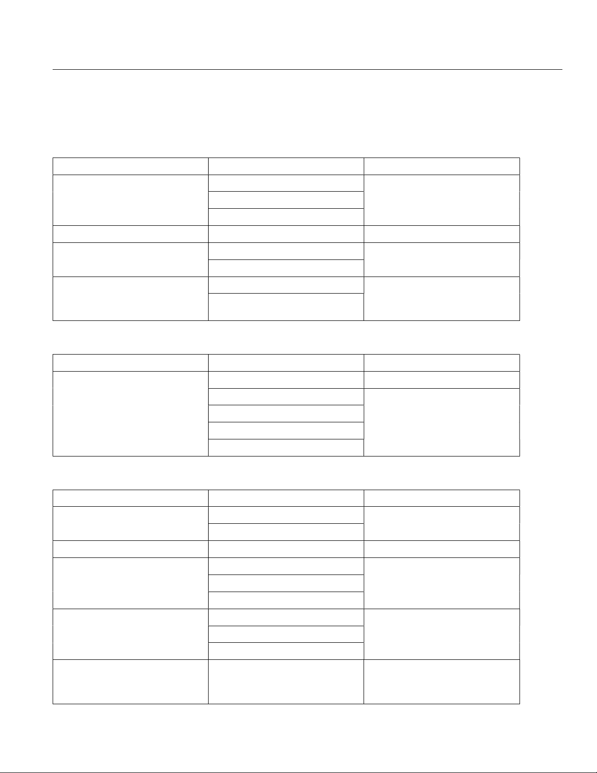
Electrical Ratings – 300A Unit
Terminal Points and Functions
Table 1: Converter Power Wiring Terminals
Function Terminal Description
AC Line Power Input H1 (L1/R) 3 Phase AC Line Power to Con-
H2 (L2/S)
H3 (L3/T)
Chassis Ground CG Ground Input
DC Power Output DC (+) DC Power to Inverter
DC (-)
AC Control Power Input FU10 (L) Single Phase AC Control Power
FU11 (N)
Table 2: Converter Control Wiring Terminals
verter (Transformer Terminals)
4160VAC 260A 50/60Hz.
6300VDC 292A
from Inverter (for Fans)
230VAC 20A 50/60Hz.
Function Terminal Description
Control Wiring to / from Converter TB1-6 (relay common) 115VAC from Inverter
TB1-6TW (relay NC contact) 3A 125VAC
TB1-6TF (relay NC contact)
TB1-6CW (relay NC contact)
TB1-6CF (relay NC contact)
Table 3: Inverter Power Wiring Terminals
Function Terminal Description
DC Bus Power Input DC (+) DC Bus Power from Converter
DC (-)
Ground CG Chassis Ground
AC Motor Power Output T1 3 Phase AC Power to Motor
T2
T3
AC Control Power Input TB1-4 (L) Single Phase AC Control Power to
TB1-5 (N)
TB1-GND
6300VDC 292A
0 to 4160VAC 300A
0 to 60Hz. PWM
Inverter
230VAC 40A 50/60Hz.
AC Control Power Output TB2-4D
TB2-5D
Single Phase AC Control Power to
Converter (for Fans)
230VAC 20A 50/60Hz.
19

M2L 3000 Series VFD
Electrical Ratings – 260A unit
Terminal Points and Functions
Table 4: Converter Power Wiring Terminals
Function Terminal Description
AC Line Power Input H1 (L1/R) 3 Phase AC Line Power to Con-
H2 (L2/S)
H3 (L3/T)
Chassis Ground CG Ground Input
DC Power Output DC (+) DC Power to Inverter
DC (-)
AC Control Power Input FU10 (L) Single Phase AC Control Power
FU11 (N)
Table 5: Converter Control Wiring Terminals
verter (Transformer Terminals)
4160VAC 230A 50/60Hz.
6300VDC 259A
from Inverter (for Fans)
230VAC 20A 50/60Hz.
Function Terminal Description
Control Wiring to / from Converter TB1-6 (relay common) 115VAC from Inverter
TB1-6TW (relay NC contact) 3A 125VAC
TB1-6TF (relay NC contact)
TB1-6CW (relay NC contact)
TB1-6CF (relay NC contact)
Table 6: Inverter Power Wiring Terminals
Function Terminal Description
DC Bus Power Input DC (+) DC Bus Power from Converter
DC (-)
Ground CG Chassis Ground
AC Motor Power Output T1 3 Phase AC Power to Motor
T2
T3
AC Control Power Input TB1-4 (L) Single Phase AC Control Power to
TB1-5 (N)
TB1-GND
6300VDC 259A
0 to 4160VAC 260A
0 to 60Hz. PWM
Inverter
230VAC 40A 50/60Hz.
AC Control Power Output TB2-4D
TB2-5D
20
Single Phase AC Control Power to
Converter (for Fans)
230VAC 20A 50/60Hz.

Common Electrical Ratings – 260A and 300A Units
Table 7: Inverter Control Wiring Terminals
Function Terminal Description
Control Wiring to / from Inverter TB5-6 115VAC to Converter
TB6-6TW 120VAC Digital Inputs
TB6-6TF
TB6-6CW
TB6-6CF
2500V optical isolation
2.3mA current draw
Off: 0-40VAC, On: 79-120VAC
2 - Specifications
Control Wiring to Shunt Trip Circuit
Breaker from Inverter
Table 8: Inverter Signal Wiring Terminals (To Customer)
Function Terminal Description
Signal Wiring from Inverter TB7-60 (AO1) 4 – 20mA Analog Outputs
Table 9: Inverter Control Wiring Terminals (From Customer)
Function Terminal Description
TB6-100 (relay NC contact) Resistive: 10A
TB6-101 (relay common)
TB6-102 (relay NO contact)
TB7-61 (AO1 COM)
TB7-62 (AO3)
TB7-63 (AO3 COM)
TB7-64 (AO2)
TB7-65 (AO2 COM)
TB7-66 (AO4)
TB7-67 (AO4 COM)
Inductive: 7A
20mA / 5VDC minimum
500V optical isolation
600 ohm load maximum
Control Wiring to Inverter TB7-68 (DI4) 120VAC Digital Inputs
TB7-69 (DI5)
TB7-70 (DI7)
TB7-71 (DI6)
TB7-80 (DI11)
TB7-81 (DI10)
TB7-82 (DI12)
2500V optical isolation
2.3mA draw
Off: 0-40VAC, On: 79-120VAC
21

M2L 3000 Series VFD
Table 10: Inverter Signal Wiring Terminals (From Customer)
Function Terminal Description
Signal Wiring to Inverter TB7-72 (AI1) 4 – 20mA Analog Inputs
TB7-73 (AI1 COM)
TB7-74 (AI3)
TB7-75 (AI3 COM)
TB7-76 (AI2)
TB7-77 (AI2 COM)
TB7-78 (AI4)
TB7-79 (AI4 COM)
Table 11: Inverter Control Wiring Terminals (To Customer)
Function Terminal Description
Control Wiring from Inverter TB7-83 (DO2) 230VAC Relay Outputs
500V optical isolation
<100 ohm input resistance
TB7-84 (L2)
TB7-85 (DO3)
TB7-86 (L1)
TB7-87 (DO4)
TB7-88 (L2)
TB7-89 (DO5)
TB7-90 (L1)
TB7-91 (DO6)
TB7-92 (L2)
2500V optical isolation
2A maximum
10mA / 5VDC minimum
22
2 - Specifications
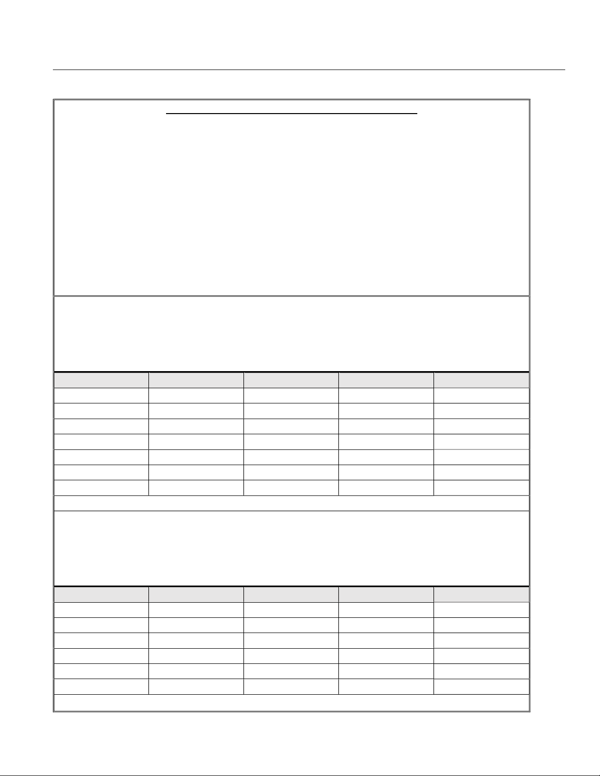
Table 12: UL Ratings Label / Nameplate 300A
MEDIUM VOLTAGE CONVERSION EQUIPMENT XXXX PA
UL MODEL NO: XCSUAC6CO + M2LU6CGE10
DESCRIPTION: CONVERTER + INVERTER
HP: 2250
NOM. INPUT: 4160 VAC, 260 A, 3Ø, 60 Hz
MAX. INPUT: 4576 VAC, 285 A.
OUTPUT: 0 – 4160 VAC, 300 A, 3Ø, 0 – 60 Hz
SHORT CIRCUIT WITHSTAND RATING: 50 KA @ 4160 V
RESISTENCIA A CORTOCIRCUITOS: 50 KA @ 4160 V
INDICE DE RESISTANCE AUX COURTS-CIRCUITS: 50 KA @ 4160 V
BIL RATING: 45 KV ALTITUDE CLASS 2000m
DILECTRIC RATING: 16975 VDC
BENSHAW ITEM NO.: XCSUAC6CO (Enclosure 1 of 2)
SERIAL NO.:
INPUT: 4160 VAC, 260A, 3Ø, 60 Hz
TRANSITION OUTPUT: 6200 VDC, 300 ADC
CONTROL VOLTAGE: 230 VAC, 20 A, 1Ø, 60 Hz (FROM Enclosure 2 of 2)
FUSE # MFR MODEL AMPS VOLTS
FU1,FU2.FU3 MERSEN A150X 300 1500
FU4,FU5,FU6 MERSEN A150X 300 1500
FU7,FU8,FU9 MERSEN A150X 300 1500
*FU10,FU11 MERSEN ATDR 20 600
FU12A,FU12B MERSEN CC1500CP 20 1500
FU13A,FU13B MERSEN CC1500CP 20 1500
FU14A,FU14B MERSEN CC1500CP 20 1500
*WARNING: FUSES MAY BE ENERGIZED / LAB-100435-01
BENSHAW ITEM NO.: M2LU6CGE10 (Enclosure 2 of 2)
SERIAL NO.:
TRANSITION INPUT: 6200 VDC, 300 ADC
OUTPUT: 0 – 4160 VAC, 300 A, 30, 0 – 60 Hz
INPUT CONTROL VOLTAGE: 230 VAC, 40 A, 10, 60 Hz
FUSE # MFR MODEL AMPS VOLTS
*FU1,FU2 MERSEN AJT 40 600
*FU3,FU4 MERSEN ATQR 10 600
*FU5,FU6 MERSEN ATQR 3 600
*FU7,FU8 MERSEN ATQR 10 600
*FU9,FU10 MERSEN ATQR 20 600
*FU11,FU12 MERSEN ATQR 15 600
*WARNING: FUSES MAY BE ENERGIZED / LAB-100436-01
23

M2L 3000 Series VFD
Table 13: UL Ratings Label / Nameplate 260A
MEDIUM VOLTAGE CONVERSION EQUIPMENT XXXX PA
UL MODEL NO: XCSUAC6CN + M2LU6CFE10
DESCRIPTION: CONVERTER + INVERTER
HP: 2000
NOM. INPUT: 4160 VAC, 230 A, 3Ø, 60 Hz
MAX. INPUT: 4576 VAC, 253 A.
OUTPUT: 0 – 4160 VAC, 300 A, 3Ø, 0 – 60 Hz
SHORT CIRCUIT WITHSTAND RATING: 50 KA @ 4160 V
RESISTENCIA A CORTOCIRCUITOS: 50 KA @ 4160 V
INDICE DE RESISTANCE AUX COURTS-CIRCUITS: 50 KA @ 4160 V
BIL RATING: 45 KV ALTITUDE CLASS 2000m
DILECTRIC RATING: 16975 VDC
BENSHAW ITEM NO.: XCSUAC6CN (Enclosure 1 of 2)
SERIAL NO.:
INPUT: 4160 VAC, 230A, 3Ø, 60 Hz
TRANSITION OUTPUT: 6200 VDC, 300 ADC
CONTROL VOLTAGE: 230 VAC, 20 A, 1Ø, 60 Hz (FROM Enclosure 2 of 2)
FUSE # MFR MODEL AMPS VOLTS
FU1,FU2.FU3 MERSEN A150X 300 1500
FU4,FU5,FU6 MERSEN A150X 300 1500
FU7,FU8,FU9 MERSEN A150X 300 1500
*FU10,FU11 MERSEN ATDR 20 600
FU12A,FU12B MERSEN CC1500CP 20 1500
FU13A,FU13B MERSEN CC1500CP 20 1500
FU14A,FU14B MERSEN CC1500CP 20 1500
*WARNING: FUSES MAY BE ENERGIZED / LAB-100442-01
BENSHAW ITEM NO.: M2LU6CFE10 (Enclosure 2 of 2)
SERIAL NO.:
TRANSITION INPUT: 6200 VDC, 259 ADC
OUTPUT: 0 – 4160 VAC, 260 A, 3Ø, 0 – 60 Hz
INPUT CONTROL VOLTAGE: 230 VAC, 40 A, 1Ø, 60 Hz
FUSE # MFR MODEL AMPS VOLTS
*FU1,FU2 MERSEN AJT 40 600
*FU3,FU4 MERSEN ATQR 10 600
*FU5,FU6 MERSEN ATQR 3 600
*FU7,FU8 MERSEN ATQR 10 600
*FU9,FU10 MERSEN ATQR 20 600
*FU11,FU12 MERSEN ATQR 15 600
*WARNING: FUSES MAY BE ENERGIZED / LAB-100443-01
24

3 - Installation
3 – Installation
EMC Installation Guidelines
General
In order to help our customers comply with European electromagnetic compatibility standards, Benshaw
Inc. has developed the following guidelines.
Attention
This product has been designed for Class A equipment. Use of the product in domestic environments may cause
radio interference, in which case the installer may need to use additional mitigation methods.
Enclosure
Install the product in a grounded metal enclosure.
Grounding
Connect a grounding conductor to the screw or terminal provided as standard on each controller. Refer to lay
out/power wiring schematic for grounding provision location.
Wiring
Refer to Wiring Practices on page 26.
25

M2L 3000 Series VFD
Wiring Considerations
Wiring Practices
When making power and control signal electrical connections, the following should be observed:
Never connect input AC power to the motor output terminals T1/U, T2/V, or T3/W.
Power wiring from the power source and to the motor must have the maximum possible physical separation-
from all other wiring. Do not run control wiring or signal wiring in the same conduit; this separation reduces
the possibility of coupling electrical noise between circuits. Minimum spacing between metallic conduits containing different wire groups should be three inches (8cm).
Minimum spacing between different wiring groups in the same wire tray should be six inches (15 cm)
Wire runs outside an enclosure should be run in metallic conduit or have shielding/armor with equivalent atten-
uation.
Whenever power and control or signal wiring cross, it should be at a 90 degree angle.
Different wire groups should be run in separate conduits.
NOTE: Local electrical codes must be adhered to for all wiring practices.
Considerations for Control and Power Wiring
Control wiring refers to wires connected to control terminal strips that normally carry 24V to 115V. AC Power wiring
refers to wires connected to the line and load terminals that normally carries 4160VAC. Power wiring for cabinet
fans carries 240VAC. DC Power wiring refers to wires connected to terminals that normally carry 6400VDC. Select
power wiring as follows:
Use only UL or CSA recognized wire.
Grounding must be in accordance with NEC, CEC, or local codes. If multiple Drives are installed, then each
Drive must be individually connected to ground. Take care not to form a ground loop. The grounds should be
connected in a STAR configuration.
Considerations for Signal Wiring
Signal wiring refers to the wires connected to control terminal strips that are low voltage signals, below 15V.
Shielded wire is recommended to prevent electrical noise interference from causing improper operation or nui-
sance tripping.
Signal wire rating should carry as high of a voltage rating as possible, normally at least 300V.
It is important to keep the routing of signal wiring as far away from control and power wiring as possible.
Meggering a Motor
If the motor needs to be meggered, remove the motor leads from the Drive before conducting the test. Failure to
comply may damage the IGBTs and WILL damage the control circuitry, which WILL NOT be replaced under warranty.
High Pot (High Potential) Testing
If the Drive needs to be high pot tested, perform a DC high pot test. The maximum high pot voltage must not exceed 8520VDC. Failure to comply WILL damage the control circuitry, which WILL NOT be replaced under warranty.
Note: For Inverter High Pot Test, both control cables connected to the sides of the Pre-Charge Board need to
be temporarily disconnected.
26

Wiring Schematics
3 - Installation
Figure 1: MV Drive System Layout
27

M2L 3000 Series VFD
Figure 2: Converter Power and Control Circuit Portions
28

Figure 3: Inverter Power and Control Circuit Portions
3 - Installation
29

M2L 3000 Series VFD
1/0 BLU-1/0S20
500 MCM
BLU-050S2
2/0 BLU-2/0S4
600 MCM
BLU-060S1
3/0 BLU-3/0S1
650 MCM
BLU-065S5
4/0 BLU-4/0S1
750 MCM
BLU-075S
250 MCM
BLU-025S 800 MCM
BLU-080S 300 MCM
BLU-030S 1000 MCM
BLU-100S
350 MCM
BLU-035S 1500 MCM
BLU-150S 400 MCM
BLU-040S4
2000 MCM
BLU-200S
1/0 BLU-1/0D20 500 MCM
BLU-050D2
2/0 BLU-2/0D4 600 MCM
BLU-060D1
3/0 BLU-3/0D1 650 MCM
BLU-065D5
4/0 BLU-4/0D1 750 MCM
BLU-075D 250 MCM
BLU-025D 800 MCM
BLU-080D
300 MCM
BLU-030D 1000 MCM
BLU-100D
350 MCM
BLU-035D 1500 MCM
BLU-150D
400 MCM
BLU-040D4
2000 MCM
BLU-200D 450 MCM BLU-045D1
Power Wiring
Input Line Requirements
The input line source needs to be an adequate source to start the motor, generally 2 times the rating of the motor
FLA. (This may not apply in some cases such as being connected to a generator).
Recommended Wire Gauges
The wire gauge selection is based on the FLA of the motor. Refer to NEC table 310, 60 or CEC Part 1, Table 2 or
local code requirements for selecting the correct wire sizing. Ensure appropriate wire derating for temperature is
applied. In some areas local codes may take precedence over the NEC or CEC. Refer to your local requirements.
Power Wire Connections
Attach the motor cables:
• Use the T1, T2 and T3 terminals. Use lugs/crimps or terminals (lugs and crimps are to be provided by the
customer).
Attach the power source cables:
• Use the L1, L2 and L3 terminals. Use lugs/crimps or terminals (lugs and crimps are to be provided by the
customer).
Compression Lugs
The following is a list of the recommended crimp-on wire connectors manufactured by Penn-Union Corp. for copper
wire.
Table 14: Single Hole Compression Lugs
Wire Size Part # Wire Size Part #
450 MCM BLU-045S1
Table 15: Two Hole Compression Lugs
Wire Size Part # Wire Size Part #
30

3 - Installation
inch (1.2mm) or less
0.047 inch (1.2mm)
value of slot width or length not corresponding to those specified above, the largest torque value associated with the
Motor Lead Length
The standard drive can operate a motor with a maximum of 600 feet of properly sized cable between the “T” leads
of the drive and those of the motor. For wire runs greater than 600 feet contact Benshaw Inc. for application assis
tance.
Input Line Requirements
The standard drive can operate with a maximum of 300 feet of properly sized cable between the converter and the
inverter.
For wire runs greater than 300 feet, contact Benshaw for application assistance.
DC Lead Length Between Converter and Inverter
The converter and inverter can be located separate from each other. However, the maximum separation distance is
limited by the voltage drop of the wiring. The wire gauge must be chosen to minimize voltage drop. The wiring should comply with all local electrical codes, as stated on previous page. Consult Benshaw for more information.
Torque Requirements for Power Wiring Terminations
Table 16: Slotted Screws and Hex Bolts
Wire size installed in
conductor
AWG or kcmil (mm²)
18 - 10 (0.82 - 5.3) 20 (2.3) 35 (4.0) 80 (9.0) 75 (8.5)
8 (8.4) 25 (2.8) 40 (4.5) 80 (9.0) 75 (8.5)
6 - 4 (13.3 - 21.2) 35 (4.0) 45 (5.1) 165 (18.6) 110 (12.4)
3 (26.7) 35 (4.0) 50 (5.6) 275 (31.1) 150 (16.9)
2 (33.6) 40 (4.5) 50 (5.6) 275 (31.1) 150 (16.9)
1 (42.4) -- -- 50 (5.6) 275 (31.1) 150 (16.9)
1/0 - 2/0 (53.5 -64.4) -- -- 50 (5.6) 385 (43.5) 180 (20.3)
3/0 - 4/0 (85.0 - 107.2) -- -- 50 (5.6) 500 (56.5) 250 (28.2)
250 - 350 (127-177) -- -- 50 (5.6) 650 (73.4) 325 (36.7)
400 (203) -- -- 50 (5.6) 825 (93.2) 375 (42.4)
500 (253) -- -- 50 (5.6) 825 (93.2) 375 (42.4)
600 - 750 (304-380) -- -- 50 (5.6) 1000 (113.0) 375 (42.4)
800 - 1000 (406-508) -- -- 50 (5.6) 1100 (124.3) 500 (56.5)
1250 - 2000 (635-1010) -- -- -- -- 1100 (124.3) 600 (67.8)
Slotted head NO.10 and larger Hexagonal head-external drive socket wrench
Slot width 0.047
and slot length ¼
inch (6.4mm) or less
Slot width over
or slot length ¼
inch (6.4mm) or
Tightening torque, pound-inches (N-m)
Split-bolt connectors Other connectors
greater
NOTE: For a
conductor size shall be marked. Slot width is the nominal design value. Slot length is measured at the bottom of the slot.
31

M2L 3000 Series VFD
Socket size across flats Tightening torque
Inches (mm) Pound-inches (N-m)
1/8 (3.2) 45 (5.1)
5/32 (4) 100 (11.3)
3/16 (4.8) 120 (13.6)
7/32 (5.6) 150 (16.9)
1/4 (6.4) 200 (22.6)
5/16 (7.9) 275 (31.1)
3/8 (9.5) 275 (42.4)
1/2 (12.7) 500 (56.5)
9/16 (14.3) 600 (67.8
NOTE: For screws with multiple tightening means, the largest torque value associated with the conductor size shall be marked. Slot length shall be measured at the
bottom of the slot..
DANGER. This equipment does not provide isolation. Separate isolating means required. Isolation devices can
take several forms with the most simple being an appropriately sized disconnect switch and contactor pair utilizing the Inverter ‘Shunt Trip’ controls, or an appropriately sized and protected vacuum circuit breaker also capable of remote operation from the inverter ‘Shunt Trip’ controls.
WARNING: Primary power source overcurrent protection is required. For disconnect switch and contactor pairs,
the components must be sized to accommodate the following fuse size ratings per chart below: (this also includes the table requirement of the list)
Table 17: Tightening Torque for Hex Screws
4160 Volt 260 Amp VFD; 300E 5500V fuse Mersen A055F2DORO-300E or equiv.
4160 Volt 300 Amp VFD; 350E 5500V fuse Mersen A055F2DORO-350E or equiv.
This unit provides electronic motor overload protection, refer to pages 77-79 for setup and operational details.
Grounding of the Inverter System: Install ground connections for the inverter system (transformer rectifier
converter and inverter) and the motor by following the correct specifications to ensure safe and accurate operation. Using the inverter and the motor without the specified grounding connections may result in electric shock
and damage to the equipment. This shall include all input, output, and DC shielded power cable connection
grounds as applicable per installation.
32

4 – Theory of Operation
4 - Theory of Operation
The Benshaw M2L 3000 family of medium voltage variable frequency motor drives features a unique power circuit, and a
state-of-the-art control platform, to provide the utmost in performance and application flexibility.
The M2L 3000 product family is forced-air cooled, and spans a power range from 300 hp to 6,200 hp, operating at industry
standard medium voltages up to 7200 VAC output. The drives can be used to control induction and wound field synchronous motors.
This section provides an overview of the drive architecture, along with descriptions of major system components.
M2L 3000 Overview
The M2L 3000 variable frequency drive consists of two major system elements, shown in Figure 4; A Converter (Input
Power Stage) and an Inverter (Output Power Stage). The purpose of the Converter is to convert incoming voltage from the
AC mains into DC. The DC is passed to the Inverter using standard high-voltage shielded cable, where it is converted into
variable voltage, variable frequency 3-phase AC, then applied to the motor.
AC
AC
Mains
Input
Power
Stage
DC
Inverter
Stage
Output
Motor
Figure 4: Benshaw M2L 3000 Block Digrams
Most modern MV VFDs employ dual energy conversions (i.e. AC-to-DC and AC-to-DC), but are constrained to have these
constituent elements located in close physical proximity to each other, to avoid electrical complications that would compromise the operation of the drive, and adversely affect reliability. The M2L 3000 is not constrained in this manner. The Inverter
can be located adjacent to, or remotely from, the Converter without causing any adverse affects on the operation of the
drive. This feature imparts great application flexibility to users who may have space constraints, or choose to locate the heat
producing Converter away from environmentally conditioned equipment rooms or spaces.
33

M2L 3000 Series VFD
Converter
The Converter, or Input Stage, consists of a medium voltage transformer and full-bridge rectifiers that convert the incoming AC mains
voltage to a fixed source of DC. Individual 3-phase bridge rectifiers
are connected in series, as shown in Figure 5, to produce the required DC voltage for the inverter.
The Converter does not contain any capacitors for energy storage.
Energy storage in the drive is distributed among identical power
modules in the drive’s Inverter. The distributed capacitive energy
storage greatly reduces arc flash potential and substantially improves reliability.
The transformer is a standard rectifier grade transformer consisting
of a single 3-phase primary winding, with three (3) secondary windings, appropriately phase shifted to yield an 18-pulse current waveform in the primary for low harmonic distortion. The total harmonic
distortion (THD) of the primary current is typically ~2.3% for a 1000
hp, 4160 VAC drive operating at full power, which easily complies
with IEEE 519 distortion requirements.
Typically, the primary voltage of the transformer is identical to the AC
operating voltage of the motor; however, the M2L 3000 can accommodate voltages that differ from the motor voltage. For example, a
customer application may require that a 4160 VAC induction motor
be operated from a 2300 VAC or 13.8k VAC source. In this case, the
primary winding would be specified to be 2300 VAC or 13.8 kVAC.
The secondary winding voltages have been selected to generate the
DC voltage needed to synthesize AC waveforms for 4160 VAC at its
output terminals.
Two typical size Converter enclosures (small and large frame) are
shown in Figure 6, with all electrical components contained within the
enclosures. The enclosure design allows for top or bottom entry of all
cable connections between the AC mains and the Inverter.
The Converter is forced-air cooled. Cooling air is drawn through filters on the front of the enclosure by multiple blowers mounted on the
top. The Converter is designed to function with “N-1 Redundancy”
(for example only 2 of 3, or 4 of 5 blowers operating), providing redundant protection and high operating availability. Filter elements are
provided in series on the front of the enclosure, to block the ingress
of dirt and dust particulates. The filter assembly mounts over a protective screen, welded to the enclosure, that prevents inadvertent
contact with the resident high voltages when the filter media is removed for cleaning or replacement.
The enclosure also contains internal baffles that route air flow
through critical areas of the transformer, and across the rectifier assemblies. Thermal sensors are located in the input air stream to the
blowers, to detect over temperature conditions. The standard Converter enclosure is rated for NEMA 1 applications. Enclosures with
other environmental ratings are available.
Figure 5: M2L 3000 Converter
Figure 6: 300 Amp Converter
34

4 – Theory of Operation
X9X7X8
X3X1X2X4X5X6+20
-20
+5%
-5%
+5%
-5%
X7X9X8
Converter Details
The standard transformer consists of a single 3-phase primary winding, with three 3phase secondary windings that are phase displaced to produce an 18-pulse current
waveform in the primary winding. The primary winding includes taps to adjust for slight
variations in the incoming line voltage, to accommodate nominal, low, or high line conditions. Variations of ±5% can be accommodated by jumpering the incoming AC cables
to the to +5% tap for high line conditions and the -5% tap for low line conditions.
Three secondary windings are physically shifted on the transformer core to yield voltages that are phase displaced by ±20 electrical degrees with respect to the primary
winding. Figure 4 shows the schematic diagram of a typical transformer.
Each secondary winding is connected to a dedicated 6-pulse, full-wave bridge rectifier
that converts AC to DC, as shown schematically in Figure 7.
The DC terminals of all three (3) rectifier bridges are connected in series, such that the
appropriate output voltage is generated at the output of the VFD.
H3
H2
H1
H3
H2
o
X4
X6
o
X5
0
H1
Figure 7: Main Transformer
Figure 8: 6-Pulse Bridge Rectifier
12, 24 and 36 pulse converters are optionally avalilable
-5%
+5%
X3
X2
o
X1
35

M2L 3000 Series VFD
Inverter
The role of the Inverter is to convert DC voltage produced by the Converter to variable voltage, variable frequency AC, to be
applied to the motor terminals. The Inverter utilizes a topology known as Modular Multi-Level Converter (M2LC), which offers
many benefits.
M2LC topology allows the Converter to be located remotely from the Inverter, for the ultimate in application flexibility. The
Inverter is a modular design enabling rapid drive repair by simple removal and replacement of a faulty module or “cell”. Replacing a cell can be done in a matter of minutes, minimizing downtime and process interruption.
IGBT Cell
The standard building block in the M2L 3000 Converter is the “cell”. A variety of cell
sizes are available, having different current ratings to configure drives at different
power levels.
A cell consists of Insulated Gate Bipolar Transistors (IGBTs), capacitors, associated
control, communication and gating circuitry, heatsinks, and sensors; all housed in a
metal enclosure. A depiction of the cell is shown below in Figure 9.
Figure 9: IGBT Cell
Each cell contains IGBT switching devices and film capacitors. These film capacitors
offer significant improvements over conventional electrolytic capacitor technologies.
This technology is more stable, and safer, than conventional capacitors that can explode from the buildup of high pressures within the capacitor if a failure should occur.
Embedded cell circuitry provides intelligence for control and communication. Communication with the central control system of the drive occurs over optical fiber, using an
Ethernet protocol that greatly improves speed and noise immunity. Each cell is designed to sense voltage and current, eliminating the need to place external voltage and
current sensors on the motor leads.
The elimination of external sensors removes single points of failure, improving drive reliability.
36

4 – Theory of Operation
CBA
AC Outputs
Inverter Packaging
A typical 4160VAC inverter contains eighteen (18) cells, arranged 6 cells per phase as
shown in Figure 7. The cells are connected in series within each phase, and the
phases are connected in parallel across the internal DC bus. DC voltage is divided
evenly among the cells in each phase.
The cells in each phase work together to create the AC output waveform. Pulse width
modulation (PWM) control is used to convert DC voltage into a low distortion AC waveform, which is applied to the motor terminals labeled A, B and C in Figure 10. Each output phase provides an equivalent waveform for optimal harmonic characteristics. As
such, output filters are not required. Additionally, the Inverter has been designed to
work with standard, non-inverter grade motors commonly found in use today.
+ DC
Cell
Cell
Cell
Cell
Cell
Cell
Cell
Cell
Cell
Cell
Cell
Cell
Cell
Cell
Cell
Cell
Cell
Cell
- DC
Figure 10: 18 Cell Inverter
The front view of a typical small frame 1500 hp Inverter is shown below in Figure 11.
Other specialized configurations of the Inverter can be utilized for higher horsepower
and/or voltage applications. The typical enclosure is partitioned into 3 sections: Cell, Input/Output and Control. The enclosure contains internal structural members that provide strength, rigidity and voltage isolation, with bolt-on metal covers for each section
attached to the structural members.
Control Section
Cell Section
Input/Output Section
Figure 11: Typical 1500 hp Inverter Front View
37

M2L 3000 Series VFD
WARNING: Do not remove the Cell or Input/Output Section covers to access the Inverter while the Inverter is energized. Potentially lethal levels
of both AC and DC voltages will be exposed which may result in serious
injury or death.
WARNING: Potentially hazardous voltages will remain in the cells until
the internal capacitors are able to de-energize. Wait at least 30 minutes
after main power is removed for the stored voltages to dissipate if removing the Inverter Cell or Input/Output section covers. Do not rely solely on
the voltage values displayed on the HMI to determine if it is safe to remove the covers on the Inverter Cell and Input/Output sections.
WARNING: The Control section contains 240V control power when active. The Control section does not contain medium voltage levels supplied from the mains, and can be carefully accessed by qualified personnel while medium voltage from the AC mains is applied to the system.
CAUTION: Special care must be taken with the cover over the Control
section and all access panels. A ground wire is attached to the inside of
that cover that ties it to ground potential. It is important that the connection integrity of this wire be maintained to avoid compromising the immunity of the Inverter to Electromagnetic Interference (EMI.).
38

4 – Theory of Operation
IGBT Cell (18)
AC Midpoint (3)
Cooling Blowers
welded to the enclosure, that prevents inadvertent contact with the resident high volt-
Hub Controller
Card Rack
I/O Rack
Converter
Connections
Motor
Connections
Figure 12: Typical 1500 hp Inverter – Front View with Covers Removed
Figure 12 represents a typical small frame, 1500 hp, 18 Cell Inverter with the front covers removed. IGBT cells can be seen as 3 vertical columns in the right side of the enclosure. The leftmost vertical column, located closest to the center of the enclosure, is
Phase A followed by Phases B and C. The AC midpoint of each phase is located behind
the grey panels covering the AC terminals and inductive filters.
Internal cabling routes the AC outputs from the phases to the Input/Output section of the
Inverter, in the area located in the lower left of the enclosure. Also shown in this section
are components associated with the pre-charge function and current loop power for the
IGBT cells.
The Input/Output section of the enclosure is the area where power connections are
made to the Inverter. AC output cables from the motor are attached to landing pads on
the right side of the Input/Output section, while high voltage cables that interconnect the
Converter and Inverter are attached to landing pads on the left side. The enclosure allows for top or bottom entry of both AC and DC cables.
The Inverter is forced-air cooled. Air is drawn through filters on the front of the enclosure
by blowers mounted on the top. The Inverter is designed to function with only 3 of the 4
blowers operating at any given time, providing redundancy and high operating availability. Two filter elements are provided in series on the front of the enclosure to block the
ingress of dirt and dust particles. The filter assembly mounts over a protective screen,
ages when the filter media is removed for cleaning or replacement.
The compartmental nature of the Inverter’s internal design provides baffling to route air
flow through critical areas of the enclosure. The standard Inverter enclosure is rated for
NEMA 1 applications.
For testing and checkout purposes, the Inverter is designed with a power supply system
that enables control power to be applied without medium voltage main power being applied.
.
39

M2L 3000 Series VFD
40

5 - Operation
5 - Operation
This section provides basic operation instructions for the M2L 3000 HMI (Human-Machine Interface) controller.
WARNING: Only qualified personnel familiar with the use and hazards of
medium voltage equipment are to perform work described in this set of
instructions.
Introduction The HMI is an interactive controller and display which provides the ability to both monitor and
control operation of the drive.
Custom parameters are accessible to modify the characteristics of drive performance. Refer to
Section 5 - Parameter List, for the complete list of user accessible parameters in tabular format,
and to Section 6 - Parameter Descriptions, for explanations of how each parameter is used. Initial
setup of basic parameters may be required for your site application, and should be configured
during drive commissioning. Many parameters can also be adjusted while the drive is running, as
noted in the parameter tables in Section 5 of this manual.
CAUTION: Parameter settings and adjustments should be performed by those
familiar with VFD and motor operation characteristics. It is not recommended
for users unfamiliar with these concepts.
41

M2L 3000 Series VFD
HMI Overview
The HMI display can be divided into three primary areas:
Selectable View Most of the HMI screen is dedicated to the active view, selectable at run time. The default view
shows Speed Setpoint, Output Frequency, and general status indicators, intended to be visible at
a distance.
Navigation Menu This menu is visible at all times, at a fixed position at the bottom of the screen. The navigation
buttons can be used to switch between different views.
Drive Controls Located to the right of the Navigation Menu, the Drive controls also remain visible regardless of
the active View.
This area will contain Start/Stop buttons when the drive is configured for HMI control, and
Running/Stopped status indicators for other control modes. If the default view is not selected, this
area will also display the output frequency while the Drive is running.
42

Status Indicators
5 - Operation
The general status indicators shown on the Main HMI view give an overview of the Drive status.
Blinking indicators on this screen are designed to draw attention so that error conditions can be
quickly resolved.
Ready This indicator will turn green when the Drive is ready to run. If the Drive is configured for HMI
control, the Start button will also turn green.
Fault The M2L 3000 is designed to detect and report various fault conditions. When a fault occurs, the
status indicator on the right and the Main button on the Navigation Menu will blink red. The name
of the latched fault will appear across the top of the screen. Refer to Section 7 - Fault Conditions,
for a complete list of Faults, descriptions and solutions.
Once the underlying cause of a fault is resolved, the fault can be cleared by pressing the Reset
button to the left of the fault name. A fault reset can also be performed by a configured digital
input, or by a plant PLC writing to the control register.
Lockout Lockout conditions will prevent the Drive from running. When any lockout occurs, the status
indicator on the right and the Lockouts Warnings Limits button will blink orange. Unlike faults,
lockouts do not latch; the lockout will clear as soon as the underlying condition is resolved, without
a manual reset.
Any lockout condition that occurs while the Drive is running will trigger a fault with the same name.
This fault is latched, so that the lockout cannot be cleared before it is seen by the operator.
Warning Warning conditions are less serious than faults or lockouts, and will not prevent the drive from
running. Some warnings, such as Cell Board Temperature, indicate that a meter is approaching
the trip point, and a fault or lockout is likely to occur. When a warning occurs, the indicator on the
right will display solid yellow. If no lockout is active, the Lockouts Warnings Limits menu button will
also turn yellow.
Limit Limits are triggered when following normal operation would cause the Drive to fault. The Drive will
temporarily ignore some parameter settings, such as Acceleration Ramp Time, in order to run
without faulting. When a limit occurs, the indicator on the right will display solid yellow. If no
lockout is active, the Lockouts Warnings Limits menu button will also turn yellow.
43

M2L 3000 Series VFD
Select Lockouts Warnings Limits from the navigation menu to view the specific lockout,
warning, and limit conditions. For each status indicator on the Main view, multiple conditions
could be present.
NOTE: Lockout, Warning, and Limit conditions are not latched indefinitely,
and can all be cleared without user interaction. Check the Event Log for
other conditions that may have already cleared.
NOTE: The HMI will automatically navigate to display the first active lockout,
warning, or limit. If other conditions are active, the additional navigation
buttons at the top of the screen will change color.
44

5 - Operation
Getting the Drive Ready
The ready state indicates that the Drive is ready to run. Until the Drive is ready, all run commands are ignored.
Apply control power to the drive. Control power provides power to run the Drive inverter and the HMI. The HMI
will turn on, and the fans on the inverter cabinet will start.
CAUTION: The drive is not equipped with a power switch of any type. Control and Main power
must be supplied separately by means of appropriate line application equipment or switchgear.
Contact Benshaw for assistance in the selection of applicable devices.
NOTE: If main power (e.g. 4160V nominal) is not applied, a “No DC Bus Fault” will occur. After
main power is applied, press the Reset button next to the fault name on the HMI
NOTE: If a series of question marks are displayed on the HMI over each display field, there is a
failure in connectivity between the Drive inverter and the HMI. Check to ensure proper seating
of the interconnection cables.
The automatic pre-charge sequence of the cell capacitors will initiate on start-up. When the pre-charge is
complete, and any fault or lockout conditions are cleared, the Main view will indicate a ready state.
45

M2L 3000 Series VFD
Operating the Drive
NOTE: Basic parameter settings for your application were set during drive
With default parameter settings, the Drive can be fully operated from buttons on the HMI. If a plant
PLC or some other control source is active, the Start and Stop buttons will not be available, and
the speed setpoint will be shown as a meter.
commissioning. If changes from those settings are required, select Parameter Settings
from the navigation menu to select and change any parameters required.
1. Navigate to the Main view.
2. Select Setpoint to set the desired speed of the motor in Hz.
NOTE: The allowable range of 0-300Hz presented by the HMI will not always match
parameter settings. If a value is entered outside of the range defined by the Minimum
Frequency and Maximum Frequency Drive parameters, the setpoint will change to the
nearest acceptable value.
3. To start the motor, select Start. The Drive will accelerate according to the Start Mode and
other parameter settings.
4. To stop the motor, select Stop. The Drive will stop the motor according to parameter settings.
NOTE: A negative setpoint is not used to run the Drive in reverse. The Run Reverse
button takes the inverse of the speed setpoint to run at a negative frequency.
NOTE: If reverse capabilities are enabled, select either Run Forward or Run Reverse to
start the motor.
NOTE: The speed setpoint can be adjusted at any time while the drive is running.
46

Selectable View Options
At any time, the navigation menu can be used to select different view options. Each view presents
different information for monitoring the Drive meters or adjusting settings.
Meter Values The Meter Values view displays real time feedback for the following values:
5 - Operation
DC Pole Voltage
This value reflects voltage stored in the system capacitors.
DC Bus Current
This value reflects the DC Bus current.
Peak Temperature (C)
This value reflects the highest measured temperature from all cell temperature monitors.
Motor Voltage LL (Line-to-Line)
This value reflects the voltage that the drive is sending to the motor.
Phase Currents
This value reflects the individual RMS motor phase currents.
Motor kW
This value reflects the real power on the motor, or “motor load in kW”.
WARNING: Potentially hazardous voltages will remain in the cells until the capacitors are
able to de-energize. Wait at least 30 minutes after main power is removed for the stored
voltages to dissipate if removing the Inverter Cell or Input/Output section covers. Do not
rely solely on the voltage values displayed on the HMI Meter Values screen to determine
if it is safe to remove the covers on the Inverter Cell and Input/Output sections.
47

M2L 3000 Series VFD
Meter Trending Real-time feedback is provided in the form of trending graphs. Two of five graphs can be
displayed at any given time that reflect the following data:
Current
The three values on this graph reflect the actual three-phase current being applied to the motor.
Ground Fault
This value reflects the ground fault analog input. The Drive is typically configured to trip when the
ground fault input exceeds 5V in either the positive or negative direction.
Motor kW
This value reflects the real power on the motor, or motor load, in kW.
Voltage
This value represents the DC Bus voltage.
Frequency
This graph shows the output frequency of the motor in green, and the frequency command in
blue.
NOTE: The scale of each meter can be changed using the Min and Max buttons below
the graph. An option in the HMI settings can be used to reset all trend ranges to their
default values.
NOTE: These values are displayed in real time only, and not stored within the system.
48

5 - Operation
Parameter Settings System parameters can be viewed and adjusted from the HMI, to customize the behavior of the
Drive. Parameter values are stored by the Drive, and retained when control power is lost. Refer to
Section 5 - Parameter List for a listing of all user accessible parameters, and Section 6 Parameter Descriptions for information regarding the usage of each parameter.
Depending on the parameter, the HMI will display either a numeric value, or a drop-down
selection.
NOTE: Some parameters cannot be changed while the drive is running. The HMI will
NOTE: A security pin can be used to lock all parameters. Each parameter can still be
display an error message, and the requested value will not be saved to the Drive.
selected to view the current value, but the HMI will not allow that value to be changed.
This lock can be adjusted in Settings.
49

M2L 3000 Series VFD
Parameter sets can be used to quickly change multiple parameter values. This optional
configuration allows the Drive to switch between different operation or load conditions without
pausing to change numerous settings.
Once parameter sets are configured, any changes made to specific parameter settings are only
saved to the active parameter set, highlighted in blue. The Edit button can be used to create and
delete parameter sets, copy all values from the active parameter set, or restore factory default
settings.
NOTE: If no parameter sets have been created, the parameter set selection buttons will
NOTE: If the parameters are locked with a security pin, the Edit button will be disabled.
NOTE: For synchronous transfer drives operating multiple motors, a parameter set must
not be displayed. Use the Edit button to generate new parameter sets.
Go to Settings to unlock parameters.
be generated for each motor. If the motors are identical, the values from parameter set 1
can be copied to all other required sets. Any additional changes to parameter settings
should then be copied across each parameter set.
50

5 - Operation
Inverter I/O This view shows the status of all inputs and outputs to the block of I/O located inside the Inverter
cabinet.
This information can be used to check control signals from the plant, and monitor any feedback. If
the analog input and output values do not match those expected by the connected device,
parameters for each I/O point can be adjusted. Section 7 - Parameter Descriptions explains how to
adjust analog I/O settings.
NOTE: The status of this screen only reflects the meter values read by the HMI, and is
not a guarantee that voltage is absent from the I/O wiring. Control power should be
removed before servicing any I/O wiring.
51

M2L 3000 Series VFD
Cell Status This view displays meter values for each individual cell in the inverter. The top menu can be used
to switch between phases (A, B, C). The cell numbers listed on the left of the screen correspond to
the physical cell layout, and can be used as a reference when testing and replacing problematic
cells.
NOTE: Yellow or red meter values indicate abnormal conditions in the cell, tied to
warnings and faults. Black text in the Capacitor Voltage columns is normal while the drive
precharges, and should change to green before precharge completes.
When any cell is faulted, the numbered indicator on the left will turn red. Specific faults can then
be viewed by pressing the button around the indicator. Multiple cells can fault at the same time,
and multiple fault conditions can be present in each cell. See Section 8 – Fault Conditions for
information on each type of cell fault.
NOTE: For Drives with 12 or more cells per phase, meters are only displayed for 1 cell at
a time, with a cell selection menu taking up most of the screen.
WARNING: Potentially hazardous voltages will remain in the cells until the capacitors are
able to de-energize. Wait at least 30 minutes after main power is removed for the stored
voltages to dissipate if removing the Inverter Cell or Input/Output section covers. Do not
rely solely on the voltage values displayed on the HMI Meter Values screen to determine
if it is safe to remove the covers on the Inverter Cell and Input/Output sections.
52

5 - Operation
RTD The system has the capability of displaying real-time feedback from an optional RTD (Resistance
Temperature Detector) module. Up to 16 RTD channels can be monitored. The warning and trip
level (in degrees Celsius) can be set individually for each RTD channel. Setting the trip level to
zero for any channel indicates that no RTD is connected, and the value will not be displayed.
Digital Output 0 from the RTD Module must be wired to one of the digital inputs of the drive as an
enable signal in order for the Drive to respond to RTD trips.
Configured as a Run Enable will stop the motor according to the programmed Stop Mode
whenever an RTD Trip occurs.
Configured as a Drive Enable will cause the Drive to coast to a stop whenever an RTD Trip
occurs, regardless of Stop Mode setting.
Digital Output 1 of the RTD module indicates when any RTD temperature is above the WARNING
level, and may be interfaced to customer control logic.
Digital Output 2 of the RTD module indicates when any RTD temperature is above the TRIP level,
and may be interfaced to customer control logic.
NOTE: If no RTD module is connected, the warning and trip levels can still be adjusted. This can
cause the HMI to display an RTD trip, but it will have no effect on the operation of the Drive.
53

M2L 3000 Series VFD
Event Log Recent events from the Drive event log can be viewed on the HMI. These events are stored in the
Drive, and are saved after a power cycle. When the Event Log button is pressed on the navigation
menu, the newest events automatically load.
Ten events at a time are displayed on the HMI, with the most recent event at the top of the list.
Use the Next and Previous buttons to navigate between older events, and the Newest button to
return to the most recent events.
Some events store additional diagnostic information, viewable as text. Use the Info button next to
any event to display the info text.
NOTE: If the Next button has been used to view older events, navigating back to the Event Log
will no longer automatically load the newest events. Use the Newest button to return to the most
recent events and re-enable this feature.
NOTE: The HMI displays a selection of the most important events. Benshaw’s Event Viewer
program for Windows can be used to load all events, and to more easily navigate to older events.
Available from Benshaw.com.
NOTE: The Event Log can also be configured as a traditional fault log; turn this option on in
Settings to show ten faults at a time, and hide all other events.
54

5 - Operation
Settings The HMI settings configure how the HMI displays information from the Drive. Unlike Parameter
Settings, these have no effect on the operation of the Drive.
Restore Trend Defaults
This button reverts all trend displays to the factory default setting. Use this option to ensure full
visibility on trended meters.
Show Faults Only
Turn this option ON to remove all non-fault events from the Event Log. This will also change the
text on the navigation menu to Fault Log.
Filter Meters
By default, all meters in the Meter Values view are displayed with a simple Window filter. This
makes the values easier to read, and less sensitive to noise. This filter is not applied to the Output
Frequency, which will always display the raw value from the Drive.
OFF
Meter values are updated as fast as the HMI can read them from the Drive, about five times per
second.
Window Sample Range: 1 - 10
Meters are displayed as an average of the last set of values read from the Drive. The Sample
setting determines the size of the window, and how often the displayed value will update.
Low Pass Sample Range: 1 - 10
Alpha Range: 0.01 - 0.99
Meters are displayed using an internal low pass filter algorithm. A higher Alpha value increases
the response of the filter. The Sample setting determines how often the display is updated with the
new calculated value.
55

M2L 3000 Series VFD
Project Type
There are three configurations of the Drive that require different view options on the HMI. Simple
variations between Drive installations, such as voltage levels and plant interface, do not require
special HMI views. This selection should be set during commissioning, and will not need to
change.
Standard
A single Inverter, controlling a single motor. This is the default option for Drives.
Sync
Synchronous Transfer. Additional Benshaw equipment allows a single inverter to control multiple
motors. Motors, one at a time, can be connected to the Drive, run to match line frequency, and
transferred across the line. All motors in a system can be connected to the line, or one motor can
be run at a variable frequency.
This option adds two new selectable views to the navigation menu, for status information of the
Synchronous Transfer PLC.
Parallel
For the highest horsepower loads, multiple Inverters are connected in parallel to run a single
motor. The HMI then shows data for all inverters, along with combined diagnostic information.
This option adds an additional menu to the HMI, described in a separate manual for Parallel
Drives.
Security
Use this button to open security settings. These settings determine if the Parameter Settings can
be changed from the HMI, and for how long. A User pin can unlock parameters for thirty minutes,
and the Master pin can be used to disable parameter protection.
NOTE: Security settings are only applied to parameters. If the HMI is configured as the
active control source, any user can still access the Start and Stop buttons in the control
area.
56

6 - Parameter List
Table 1
8: DRIVE Group
Parameter List
DRIVE Group Parameter List
6 – Parameter List
Parameter Description Units / Range Default
DRIVE-00 Motor Type
DRIVE-01 Motor Rated Current 1.0 – 6000.0 A 126.0 No 40048
DRIVE-02 Motor Rated Voltage 100 – 15000 V 4160 No 40050
DRIVE-03 Motor Base Frequency 20.00 – 300.00 Hz 60.00 No 40051
DRIVE-04 Motor Rated kW 0 – 50000 kW 746 Yes 40174
DRIVE-05 Motor Poles 2 – 36 4 No 40053
DRIVE-06 Motor Rated Slip 0.00 – 10.00 Hz 1.00 No 40052
DRIVE-07 Reverse Enable
DRIVE-08 Starting Frequency 0.00 – 10.00 Hz 0.10 Yes 40047
DRIVE-09 Minimum Frequency 0.00 – 300.00 Hz 0.00 Yes 44489
DRIVE-10 Maximum Frequency 1.00 – 300.00 Hz 60.00 Yes 40046
DRIVE-11 Acceleration Ramp Time 0.0 – 1200.0 Sec 120.0 Yes 40040
0: Induction
1: Synchronous
0: Disabled
1: Enabled
Induction Yes 40173
Disabled No 44484
Adjust Dur-
ing Run?
Modbus Reg-
ister
DRIVE-12 Acceleration Profile
DRIVE-13 Acceleration S Curve Factor 1 – 99% 50 No 40042
DRIVE-14 Deceleration Ramp Time 0.0 – 1200.0 Sec 120.0 Yes 40043
DRIVE-15 Deceleration Profile
DRIVE-16 Deceleration S Curve Factor 1 – 99% 50 No 40045
0: Linear
1: U Curve
2: S Curve
0: Linear
1: U Curve
2: S Curve
Linear No 40041
Linear No 40044
57

M2L 3000 Series VFD
Table
19:
FUNCTION Group Parameter List
Level
Ratio
Frequency
Frequency Point
Point
FUNCTION Group Parameter List
Parameter Description Units / Range Default
FUNCTION-00 Start Mode
FUNCTION-01 Stop Mode
FUNCTION-02 Brake Output Frequency 0.10 – 5.00 Hz 0.10 Yes 40160
FUNCTION-03 Starting Brake Time 0.1 – 300.0 sec 0.1 Yes 40162
FUNCTION-04 Starting Brake Level 1 – 100% 1 Yes 40163
FUNCTION-05 Stop Delay Time 0.1 – 60.0 Sec 10.0 Yes 40133
FUNCTION-06 Coast to Brake Time 0.1 – 10.0 sec 0.1 Yes 40156
FUNCTION-07 Stopping Brake Time 0.1 – 300.0 sec 0.1 Yes 40157
FUNCTION-08 Stopping Brake Level 1 – 100% 1 Yes 40158
FUNCTION-09 Decel to Brake Frequency 0.10 – 300.0 Hz 20.00 Yes 40159
0: Accel
1: Flying Start
2: DC Brake then Start
0: Coast to Stop
1: Decel
2: Coast then DC Brake
3: Decel then DC Brake
Accel No 40161
Decel No 40068
Adjust
During Run?
Modbus Reg-
ister
FUNCTION-10 Motor Thermal Overload Enable
FUNCTION-11 Motor Thermal Overload Level 100 – 300% 110 Yes 40073
FUNCTION-12 Motor Thermal Overload Time 0 – 300 sec 60 Yes 40074
FUNCTION-13
FUNCTION-14 Motor Service Factor 1.00 – 1.25 1.00 Yes 40129
FUNCTION-15
FUNCTION-16 Motor Cooling Type
FUNCTION-17 Motor Cooling Time 0 – 60000 sec 1200 Yes 40075
FUNCTION-18
FUNCTION-19
FUNCTION-20
FUNCTION-21 Overcurrent Enable
Motor Thermal Overload Release
Motor Thermal Overload Hot/Cold
Motor Self Cool Derate Level at Zero
Motor Self Cool Derate Level at
Motor Self Cool Derate Frequency
0: Disabled
1: Enabled
1 – 99% 60 Yes 40137
0 – 99% 0 Yes 40130
0: Self Cooled
1: Blower Cooled
0 – 100% 65 Yes 40149
0 – 100% 95 Yes 40151
0.0 – 300.0 Hz 20.0 Yes 40150
0: Disabled
1: Enabled
Enabled Yes 40071
Self Cooled Yes 40072
Disabled Yes 40076
58

Table 19: FUNCTION Group Parameter List
1:
Enabled
1:
Enabled
1:
Enabled
18: DeviceNet
6 – Parameter List
Parameter Description Units / Range Default
FUNCTION-22 Overcurrent Level 1 – 300% 120 Yes 40077
FUNCTION-23 Overcurrent Trip Time 0.0 – 600.0 sec 0.1 Yes 40078
FUNCTION-24 Undercurrent Enable
FUNCTION-25 Undercurrent Level 1 – 99% 1 Yes 40135
FUNCTION-26 Undercurrent Trip Time 0.0 – 600.0 sec 0.1 Yes 40136
FUNCTION-27 Output Phase Loss Enable
FUNCTION-28 Output Phase Loss Level 50 – 150% 90 Yes 40080
FUNCTION-29 Output Phase Loss Trip Time 0.1 – 600.0 sec 0.1 Yes 40081
FUNCTION-30 Backspin Lockout Enable
FUNCTION-31 Backspin Lockout Time 10 – 3600 sec 10 Yes 44491
0: Disabled
0: Disabled
0: Disabled
Disabled Yes 40134
Disabled Yes 40079
Disabled Yes 44490
Adjust
During Run?
Modbus Reg-
ister
FUNCTION-32 Local Control Source
FUNCTION-33 Remote Control Source Digital Input No 44449
FUNCTION-34 Local Speed Reference Source
FUNCTION-35 Remote Speed Reference Source
FUNCTION-36 Controller IP Address 1 0 – 255 172
FUNCTION-37 Controller IP Address 2 0 – 255 29
FUNCTION-38 Controller IP Address 3 0 – 255 87
0: Digital Input
1: HMI
2: Modbus TCP
3: DeviceNet
0: HMI
1: Inverter Analog Inpt 1
2: Inverter Analog Inpt 2
3: Inverter Analog Inpt 3
4: Inverter Analog Inpt 4
5: Inverter Analog Inpt 5
6: Inverter Analog Inpt 6
7: Inverter Analog Inpt 7
8: Inverter Analog Inpt 8
9: CCI Analog Input 1
10: CCI Analog Input 2
11: CCI Analog Input 3
12: CCI Analog Input 4
13: CCI Analog Input 5
14: CCI Analog Input 6
15: CCI Analog Input 7
16: CCI Analog Input 8
17: Modbus TCP
HMI No 44448
HMI No 44452
Analog
Input 3
No 44453
No 44454
No 44455
No 44456
FUNCTION-39 Controller IP Address 4 0 – 255 15
No 44457
59

M2L 3000 Series VFD
Table 19: FUNCTION Group Parameter List
Parameter Description Units / Range Default
FUNCTION-40 Modbus Master Timeout 0.0 – 600.0 sec 0 Yes 44662
FUNCTION-41 Modbus Master IP Address 1 0 – 255 0 Yes 44663
FUNCTION-42 Modbus Master IP Address 2 0 – 255 0 Yes 44664
FUNCTION-43 Modbus Master IP Address 3 0 – 255 0 Yes 44665
FUNCTION-44 Modbus Master IP Address 4 0 – 255 0 Yes 44666
FUNCTION-45 Year 2000 – 2136 - Yes 44691
FUNCTION-46 Month 1 – 12 - Yes 44692
FUNCTION-47 Day 1 – 31 - Yes 44693
FUNCTION-48 Hour 0 – 23 - Yes 44694
FUNCTION-49 Minute 0 – 59 - Yes 44695
FUNCTION-50 Second 0 – 59 - Yes 44696
Adjust
During Run?
Modbus Reg-
ister
60

AFN (Advanced Function) Group Parameter List
Table
20: AFN (Advanced Function) Group Parameter List
6 – Parameter List
Parameter Description Units / Range Default
AFN-00 Skip Frequency Enable
AFN-01 Skip Frequency Low 1 0.00 – 300.00 Hz 20.00 Yes 40140
AFN-02 Skip Frequency High 1 0.00 – 300.00 Hz 21.00 Yes 40141
AFN-03 Skip Frequency Low 2 0.00 – 300.00 Hz 30.00 Yes 40142
AFN-04 Skip Frequency High 2 0.00 – 300.00 Hz 31.00 Yes 40143
AFN-05 Skip Frequency Low 3 0.00 – 300.00 Hz 40.00 Yes 40144
AFN-06 Skip Frequency High 3 0.00 – 300.00 Hz 41.00 Yes 40145
AFN-07 Dwell Enable
AFN-08 Dwell Frequency 0.00 – 300.00 Hz 0.00 Yes 40147
AFN-09 Dwell Time 0.01 – 600.00 sec 0.01 Yes 40148
AFN-10 Flying Start Current Level 1 – 99% 25 Yes 40164
AFN-11 Flying Start Current Application Time 0.01 – 10.00 sec 5.00 Yes 40165
0: Disabled
1: Enabled
0: Disabled
1: Enabled
Disabled Yes 40139
Disabled Yes 40146
Adjust During
Run?
Modbus Reg-
ister
AFN-12 Flying Start Initial Frequency 0.00 – 60.00 Hz 60 Hz Yes 40197
AFN-13 Flying Start Frequency Ramp Time 0.01 – 30.00 sec 30.00 Yes 40166
AFN-14 Flying Start Current Threshold 1 – 50% 15 Yes 40167
AFN-15 Control Fault Stop Enable
AFN-16 Auto Start
AFN-17 Motor No Load Current 1.0 – 6000.0 A 33.0 No 40049
AFN-18 Motor Rotor Time Constant 0.01 – 10.00 sec 1.00 Yes 40127
AFN-19 Motor Magnetizing Inductance 0.000 – 20.000 pu 3.500 Yes 40125
AFN-20 Motor Leakage Inductance 0.000 – 0.500 pu 0.200 Yes 40126
AFN-21 Motor Stator Resistance 0.000 – 30.000 pu 0.020 Yes 40122
0: Disabled
1: Enabled
0: Disabled
1: Power
2: Fault
3: Power & Fault
Enabled Yes 40069
Disabled No 44450
61

M2L 3000 Series VFD
Table
21:
I/O (Input/Output) Group Parameter List
Warning
Fault
FBK
Function
Contactor
I/O (Input/Output) Group Parameter List
Parameter Description Units / Range Default
I/O-00 Inverter Digital In #1 Function For Internal Use Only
I/O-01 Inverter Digital In #2 Function For Internal Use Only
I/O-02 Inverter Digital In #3 Function For Internal Use Only
I/O-03 Inverter Digital In #4 Function
I/O-04 Inverter Digital In #5 Function Run FWD No 44317
I/O-05 Inverter Digital In #6 Function Run REV No 44318
I/O-06 Inverter Digital In #7 Function Stop No 44319
I/O-07 Inverter Digital In #8 Function None No 44320
I/O-08 Inverter Digital In #9 Function None No 44321
I/O-09 Inverter Digital In #10 Function None No 44322
I/O-10 Inverter Digital In #11 Function None No 44323
I/O-11 Inverter Digital In #12 Function None No 44324
I/O-12 Inverter Digital In #13 Function None No 44325
I/O-13 Inverter Digital In #14 Function None No 44326
I/O-14 Inverter Digital In #15 Function None No 44327
I/O-15 Inverter Digital In #16 Function None No 44328
0: None
1: Run FWD
2: Run REV
3: Stop
4: Fault Reset
5: Run Enable
6: Run Disable
7: Local/Remote
8: DC Brake Enable
9: DC Brake Disable
10: External Fault High
11: External Fault Low
12: Drive Enable
13: Drive Disable
14: Input Phase Fault High
15: Transformer Fault Low
16: Transformer Warning Low
17: Converter Warning Low
18: Converter Fault Low
19: Main Contactor Feedback
20: Output Contactor Feedback
21: Input Disconnect Feedback
22: Output Disconnect
Feedback
23: DC Link Reactor Warning
24: DC Link Reactor Fault
25: Output Reactor Warning
26: Output Reactor Fault
Converter
Converter
Main Cont
None No 44316
Adjust During
Run?
No 44313
No 44314
No 44315
Modbus
Register
I/O-16
Inverter Digital Out #1
62
For Internal Use Only
Precharge
No 44330

6 – Parameter List
Table
21:
I/O (Input/Output) Group Parameter List
Reference
Parameter Description Units / Range Default
I/O-17
I/O-18
I/O-19
I/O-20
I/O-21
I/O-22
I/O-23
I/O-24
I/O-25
I/O-26
I/O-27
I/O-28
I/O-29
I/O-30
Inverter Digital Out #2
Function
Inverter Digital Out #3
Function
Inverter Digital Out #4
Function
Inverter Digital Out #5
Function
Inverter Digital Out #6
Function
Inverter Digital Out #7
Function
Inverter Digital Out #8
Function
Inverter Digital Out #9
Function
Inverter Digital Out #10
Function
Inverter Digital Out #11
Function
Inverter Digital Out #12
Function
Inverter Digital Out #13
Function
Inverter Digital Out #14
Function
Inverter Digital Out #15
Function
0: None
1: Run
2: Fault - Non Fail Safe
3: Fault - Fail Safe
4: Ready
5: At Speed
6: Forward
7: Reverse
8: DC Brake Active
9: Local Control Source Active
10: Remote Control Source
Active
11: Stopped
12: Warning
13: Overcurrent Warning
14: Undercurrent Warning
15: Motor Overload Warning
16: Drive Overload Warning
17: Motor Overload Trip
18: Drive Overload Trip
19: Bus Overvoltage Trip
20: Bus Undervoltage Trip
21: Cell Fault
22: Ground Fault Trip
23: Precharged
24: Precharge Contactor
25: Lockout Active
26: Main Contactor
27: Output Contactor Control
28: Shunt Trip NFS
29: Shunt Trip FS
None No 44331
None No 44332
None No 44333
None No 44334
None No 44335
None No 44336
None No 44337
None No 44338
None No 44339
None No 44340
None No 44341
None No 44342
None No 44343
None No 44344
Adjust During
Run?
Modbus
Register
I/O-31
I/O-32 Inverter Analog In #1 Function For Internal Use Only Ground Fault No 44347
I/O-33 Inverter Analog In #2 Function
I/O-34 Inverter Analog In #3 Function
I/O-35 Inverter Analog In#4 Function None No 44350
I/O-36 Inverter Analog In #5 Function None No 44351
I/O-37 Inverter Analog In #6 Function None No 44352
I/O-38 Inverter Analog In #7 Function None No 44353
I/O-39 Inverter Analog In #8 Function None No 44354
I/O-40 Inverter AI #1 Process - Low -100.0 – 100.0% 0.0 Yes 44356
Inverter Digital Out #16
Function
0: None
1: Speed Reference
None No 44345
None No 44348
Speed
No 44349
63

M2L 3000 Series VFD
Table
21:
I/O (Input/Output) Group Parameter List
Parameter Description Units / Range Default
I/O-41 Inverter AI #1 In - Low -10.0 – 20.0 0.0 Yes 44357
I/O-42 Inverter AI #1 Process - High -100.0 – 100.0% 100.0 Yes 44358
I/O-43 Inverter AI #1 In - High -10.0 – 20.0 10.0 Yes 44359
I/O-44 Inverter AI #2 Process - Low -100.0 – 100.0% 0.0 Yes 44361
I/O-45 Inverter AI #2 In - Low -10.0 – 20.0 0.0 Yes 44362
I/O-46 Inverter AI #2 Process - High -100.0 – 100.0% 100.0 Yes 44363
I/O-47 Inverter AI #2 In - High -10.0 – 20.0 10.0 Yes 44364
I/O-48 Inverter AI #3 Process - Low -100.0 – 100.0% 0.0 Yes 44366
I/O-49 Inverter AI #3 In - Low -10.0 – 20.0 4.0 Yes 44367
I/O-50 Inverter AI #3 Process - High -100.0 – 100.0% 100.0 Yes 44368
I/O-51 Inverter AI #3 In - High -10.0 – 20.0 20.0 Yes 44369
Adjust During
Run?
Modbus
Register
I/O-52 Inverter AI #4 Process - Low -100.0 – 100.0% 0.0 Yes 44371
I/O-53 Inverter AI #4 In - Low -10.0 – 20.0 4.0 Yes 44372
I/O-54 Inverter AI #4 Process - High -100.0 – 100.0% 100.0 Yes 44373
I/O-55 Inverter AI #4 In - High -10.0 – 20.0 20.0 Yes 44374
I/O-56 Inverter AI #5 Process - Low -100.0 – 100.0% 0.0 Yes 44376
I/O-57 Inverter AI #5 In - Low -10.0 – 20.0 4.0 Yes 44377
I/O-58 Inverter AI #5 Process - High -100.0 – 100.0% 100.0 Yes 44378
I/O-59 Inverter AI #5 Inp - High -10.0 – 20.0 20.0 Yes 44379
I/O-60 Inverter AI #6 Process - Low -100.0 – 100.0% 0.0 Yes 44381
I/O-61 Inverter AI #6 In - Low -10.0 – 20.0 4.0 Yes 44382
I/O-62 Inverter AI #6 Process - High -100.0 – 100.0% 100.0 Yes 44383
I/O-63 Inverter AI #6 In- High -10.0 – 20.0 20.0 Yes 44384
I/O-64 Inverter AI #7 Process - Low -100.0 – 100.0% 0.0 Yes 44386
64

6 – Parameter List
Table
21:
I/O (Input/Output) Group Parameter List
Parameter Description Units / Range Default
I/O-65 Inverter AI #7 In - Low -10.0 – 20.0 0.0 Yes 44387
I/O-66 Inverter AI #7 Process - High -100.0 – 100.0% 100.0 Yes 44388
I/O-67 Inverter AI #7 In - High -10.0 – 20.0 10.0 Yes 44389
I/O-68 Inverter AI #8 Process - Low -100.0 – 100.0% 0.0 Yes 44391
I/O-69 Inverter AI #8 In - Low -10.0 – 20.0 0.0 Yes 44392
I/O-70 Inverter AI #8 Process - High -100.0 – 100.0% 100.0 Yes 44393
I/O-71 Inverter AI #8 Input - High -10.0 – 20.0 10.0 Yes 44394
I/O-72
I/O-73
I/O-74
I/O-75
I/O-76
I/O-77
I/O-78
I/O-79
Inverter Analog Out #1
Function
Inverter Analog Out #2
Function
Inverter Analog Out #3
Function
Inverter Analog Out #4
Function
Inverter Analog Out #5
Function
Inverter Analog Out #6
Function
Inverter Analog Out #7
Function
Inverter Analog Out #8
Function
0: None
1: Output Frequency
2: Output Freq Magnitude
3: Freq Command
4: Freq Cmd Magnitude
5: Output Voltage
6: Inverter Output Current
7: Inverter Output kW
8: DC Bus V
9: Drive Output Current
10: Drive Output kW
11: Inverter AI 1
12: Inverter AI 2
13: Inverter AI 3
14: Inverter AI 4
15: Inverter AI 5
16: Inverter AI 6
17: Inverter AI 7
18: Inverter AI 8
19: CCI AI 1
20: CCI AI 2
21: CCI AI 3
22: CCI AI 3
23: CCI AI 5
24: CCI AI 6
25: CCI AI 7
26: CCI AI 8
27: Cal + 100%
28: Cal - 100%
None No 44396
None No 44397
None No 44398
None No 44399
None No 44400
None No 44401
None No 44402
None No 44403
Adjust During
Run?
Modbus
Register
I/O-80 Inverter AO #1 Process - Low -100.0 – 100.0% 0.0 Yes 44405
I/O-81 Inverter AO #1 Output - Low -10.0 – 20.0 0.0 Yes 44406
I/O-82 Inverter AO #1 Process - High -100.0 – 100.0% 100.0 Yes 44407
I/O-83 Inverter AO #1 Out- High -10.0 – 20.0 10.0 Yes 44408
I/O-84 Inverter AO #2 Process - Low -100.0 – 100.0% 0.0 Yes 44410
I/O-85 Inverter AO #2 Out - Low -10.0 – 20.0 0.0 Yes 44411
I/O-86 Inverter AO #2 Process - High -100.0 – 100.0% 100.0 Yes 44412
I/O-87 Inverter AO #2 Out - High -10.0 – 20.0 10.0 Yes 44413
65

M2L 3000 Series VFD
Table
21:
I/O (Input/Output) Group Parameter List
I/O-96 Inverter
AO #5 Process
- Low -
100.0
– 100.0%
0.0 Yes 44425
I/O-101 Inverter AO #6 Out
- Low -
10.0 –
20.0 4.0 Yes 44431
I/O-103 Inverter AO #6 Out
- High -
10.0 –
20.0 20.0 Yes 44433
I/O-104 Inverter
AO #7 Process
- Low -
100.0
– 100.0%
0.0 Yes 44435
I/O-106 Inverter
AO #7 Process
- High -
100.0
– 100.0%
100.0
Yes 44437
I/O-109 Inverter AO #8 Out
- Low -
10.0 –
20.0 4.0 Yes 44441
I/O-110 Inverter
AO #8 Process
- High -
100.0
– 100.0%
100.0
Yes 44442
I/O-111 Inverter AO #8 Out
- High -
10.0 –
20.0 20.0 Yes 44443
Parameter Description Units / Range Default
I/O-88 Inverter AO #3 Process - Low -100.0 – 100.0% 0.0 Yes 44415
I/O-89 Inverter AO #3 Out - Low -10.0 – 20.0 0.0 Yes 44416
I/O-90 Inverter AO #3 Process - High -100.0 – 100.0% 100.0 Yes 44417
I/O-91 Inverter AO #3 Out - High -10.0 – 20.0 10.0 Yes 44418
I/O-92 Inverter AO #4 Process - Low -100.0 – 100.0% 0.0 Yes 44420
I/O-93 Inverter AO #4 Out - Low -10.0 – 20.0 0.0 Yes 44421
I/O-94 Inverter AO #4 Process - High -100.0 – 100.0% 100.0 Yes 44422
I/O-95 Inverter AO #4 Out - High -10.0 – 20.0 10.0 Yes 44423
I/O-97 Inverter AO #5 Out - Low -10.0 – 20.0 4.0 Yes 44426
I/O-98 Inverter AO #5 Process - High -100.0 – 100.0% 100.0 Yes 44427
I/O-99 Inverter AO #5 Out - High -10.0 – 20.0 20.0 Yes 44428
I/O-100 Inverter AO #6 Process - Low -100.0 – 100.0% 0.0 Yes 44430
Adjust During
Run?
Modbus
Register
I/O-102 Inverter AO #6 Process - High -100.0 – 100.0% 100.0 Yes 44432
I/O-105 Inverter AO #7 Out - Low -10.0 – 20.0 4.0 Yes 44436
I/O-107 Inverter AO #7 Out - High -10.0 – 20.0 20.0 Yes 44438
I/O-108 Inverter AO #8 Process - Low -100.0 – 100.0% 0.0 Yes 44440
66

6 – Parameter List
Table
21:
I/O (Input/Output) Group Parameter List
I/O-112
CCI Digital In #1 Function
None No 44401
I/O-113
CCI Digital In #2
Function
None No 44
502 I/O-114
CCI Digital In #3
Function
None No 4
4503
Parameter Description Units / Range Default
I/O-115 CCI Digital In #4 Function None No 44504
I/O-116 CCI Digital In #5 Function None No 44505
I/O-117 CCI Digital In #6 Function None No 44506
I/O-118 CCI Digital In #7 Function None No 44507
I/O-119 CCI Digital In #8 Function None No 44508
I/O-120 CCI Digital In #9 Function None No 44509
I/O-121 CCI Digital In #10 Function None No 44510
I/O-122 CCI Digital In #11 Function None No 44511
I/O-123 CCI Digital In #12 Function None No 44512
I/O-124 CCI Digital In #13 Function None No 44513
I/O-125 CCI Digital In #14 Function None No 44514
I/O-126 CCI Digital In #15 Function None No 44515
0: None
1: Run FWD
2: Run REV
3: Stop
4: Fault Reset
5: Run Enable
6: Run Disable
7: Local/Remote
8: DC Brake Enable
9: DC Brake Disable
10: External Fault High
11: External Fault Low
12: Drive Enable
13: Drive Disable
14: Input Phase Fault High
15: Transformer Fault Low
16: Transformer Warning Low
17: Converter Warning Low
18: Converter Fault Low
19: Main Contactor Feedback
Adjust During
Run?
Modbus
Register
I/O-127 CCI Digital In #16 Function None No 44516
67

M2L 3000 Series VFD
Table
21:
I/O (Input/Output) Group Parameter List
I/O-136
CCI Digital Out
#9
Function
None No 44525
HIgh
Parameter Description Units / Range Default
I/O-128
I/O-129 CCI Digital Out #2 Function None No 44518
I/O-130 CCI Digital Out #3 Function None No 44519
I/O-131 CCI Digital Out #4 Function None No 44520
I/O-132 CCI Digital Out #5 Function None No 44521
I/O-133 CCI Digital Out #6 Function None No 44522
I/O-134 CCI Digital Out #7 Function None No 44523
I/O-135 CCI Digital Out #8 Function None No 44524
I/O-137 CCI Digital Out #10 Function None No 44526
I/O-138 CCI Digital Out #11 Function None No 44527
I/O-139 CCI Digital Out #12 Function None No 44528
I/O-140 CCI Digital Out #13 Function None No 44529
I/O-141 CCI Digital Out #14 Function None No 44530
I/O-142 CCI Digital Out #15 Function None No 44531
CCI Digital Out #1 Function
0: None
1: Run
2: Fault - Non Fail Safe
3: Fault - Fail Safe
4: Ready
5: At Speed
6: Forward
7: Reverse
8: DC Brake Active
9: Local Control Source
Active
10: Remote Control Source
Active
11: Stopped
12: Warning
13: Overcurrent Warning
14: Undercurrent Warning
15: Motor Overload Warning
16: Drive Overload Warning
17: Motor Overload Trip
18: Drive Overload Trip
19: Bus Overvoltage Trip
20: Bus Undervoltage Trip
21: Cell Fault
22: Ground Fault Trip
23: Precharged
24: Precharge Contactor
25: Lockout Active
26: Main Contactor
None No 44517
Adjust During
Run?
Modbus
Register
I/O-143 CCI Digital Out #16 Function None No 44532
I/O-144
I/O-145 CCI Analog In #2 Function
I/O-146 CCI Analog In #3 Function None No 44535
I/O-147 CCI Analog In #4 Function None No 44536
I/O-148 CCI Analog In #5 Function None No 44537
I/O-149 CCI Analog In #6 Function None No 44538
I/O-150 CCI Analog In #7 Function None No 44539
I/O-151 CCI Analog In #8 Function None No 44540
I/O-152
I/O-153
I/O-154 CCI Analog In #1 Process
I/O-155
CCI Analog In #1 Function For Internal Use Only
0: None
1: Speed Reference
CCI Analog In #1 Process Low -100.0 – 100.0% 0.0 Yes 44542
CCI Analog In #1 Input Low -10.0 – 20.0 4.0V or mA Yes 44543
-100.0 – 100.0% 100.0% Yes 44544
CCI Analog In #1 Input HIgh -10.0 – 20.0 20.0V or mA Yes
None No 44533
None No 44534
68
44545

6 – Parameter List
Table
21:
I/O (Input/Output) Group Parameter List
High
H
igh
H
igh
H
igh
H
igh
High
Parameter Description Units / Range Default
I/O-156
I/O-157 CCI Analog In #2 Process Low
I/O-158 CCI Analog In #2 Process
I/O-159
I/O-160 CCI Analog In #3 Process Low
I/O-161 CCI Analog In #3 Input Low
I/O-162 CCI Analog In #3 Process
I/O-163 CCI Analog In #3 Input High
I/O-164 CCI Analog In #4 Process Low
I/O-165 CCI Analog In #4 Input Low
I/O-166 CCI Analog In #4 Process
I/O-167 CCI Analog In #4 Input High
CCI Analog In #2 Process Low -100.0 – 100.0% 0.0% Yes
-10.0 – 20.0 4.0V or mA Yes
-100.0 – 100.0% 100.0% Yes
CCI Analog In #2 Input High -10.0 – 20.0 20.0V or mA Yes
-100.0 – 100.0% 0.0% Yes
-10.0 – 20.0 4.0V or mA Yes
-100.0 – 100.0% 100.0% Yes
-10.0 – 20.0 20.0V or mA Yes
-100.0 – 100.0% 0.0% Yes
-10.0 – 20.0 4.0V or mA Yes
-100.0 – 100.0% 100.0% Yes
-10.0 – 20.0 20.0V or mA Yes
Adjust During
Run?
Modbus
Register
44547
44548
44549
44550
44552
44553
44554
44555
44557
44558
44559
44560
I/O-168 CCI Analog In #5 Process Low
I/O-169 CCI Analog In #5 Input Low
I/O-170 CCI Analog In #5 Process
I/O-171 CCI Analog In #5 Input High
I/O-172 CCI Analog In #6 Process Low
I/O-173 CCI Analog In #6 Input Low
I/O-174 CCI Analog In #6 Process
I/O-175 CCI Analog In #6 Input High
I/O-176 CCI Analog In #7 Process Low
I/O-177 CCI Analog In #7 Input Low
I/O-178 CCI Analog In #7 Process
I/O-179 CCI Analog In #7 Input High
I/O-180 CCI Analog In #8 Process Low
I/O-181 CCI Analog In #8 Input Low
-100.0 – 100.0% 0.0% Yes
-10.0 – 20.0 4.0V or mA Yes
-100.0 – 100.0% 100.0% Yes
-10.0 – 20.0 20.0V or mA Yes
-100.0 – 100.0% 0.0% Yes
-10.0 – 20.0 4.0V or mA Yes
-100.0 – 100.0% 100.0% Yes
-10.0 – 20.0 20.0V or mA Yes
-100.0 – 100.0% 0.0% Yes
-10.0 – 20.0 4.0V or mA Yes
-100.0 – 100.0% 100.0% Yes
-10.0 – 20.0 20.0V or mA Yes
-100.0 – 100.0% 0.0% Yes 44577
-10.0 – 20.0 4.0V or mA Yes
44562
44563
44564
44565
44567
44568
44569
44570
44572
44573
44574
44575
44578
69

M2L 3000 Series VFD
Table
21:
I/O (Input/Output) Group Parameter List
H
igh
Low
H
igh
High
Low
High
High
Low
Parameter Description Units / Range Default
I/O-182 CCI Analog In #8 Process
I/O-183
I/O-184
I/O-185 CCI Analog Out #2 Funtion None No
I/O-186 CCI Analog Out #3 Funtion None No
I/O-187 CCI Analog Out #4 Funtion None No
I/O-188 CCI Analog Out #5 Funtion None No
I/O-189 CCI Analog Out #6 Funtion None No
I/O-190 CCI Analog Out #7 Funtion None No
I/O-191 CCI Analog Out #8 Funtion
CCI Analog In #8 Input High -10.0 – 20.0 20.0V or mA Yes 44580
CCI Analog Out #1 Funtion
-100.0 – 100.0% 100.0% Yes
0: None
1: Output Frequency
2: Output Freq Magnitude
3: Freq Command
4: Freq Cmd Magnitude
5: Output Voltage
6: Inverter Output Current
7: Inverter Output kW
8: DC Bus V
9: Drive Output Current
10: Drive Output kW
11: Inverter AI 1
12: Inverter AI 2
13: Inverter AI 3
14: Inverter AI 4
15: Inverter AI 5
16: Inverter AI 6
17: Inverter AI 7
18: Inverter AI 8
19: CCI AI 1
20: CCI AI 2
21: CCI AI 3
22: CCI AI 3
23: CCI AI 5
24: CCI AI 6
25: CCI AI 7
26: CCI AI 8
27: Cal + 100%
28: Cal - 100%
None No 44581
None No 44588
Adjust During
Run?
Modbus
Register
44579
44582
44583
44584
44585
44586
44587
I/O-192 CCI Analog Out #1 Process
I/O-193
I/O-194 CCI Analog Out #1 Process
I/O-195 CCI Analog Out #1 Output
I/O-196 CCI Analog Out #2 Process
I/O-197
I/O-198 CCI Analog Out #2 Process
I/O-199 CCI Analog Out #2 Output
I/O-200 CCI Analog Out #3 Process
I/O-201
CCI Analog Out #1 Output Low -10.0 – 20.0 4.0V or mA Yes 44591
CCI Analog Out #2 Output Low -10.0 – 20.0 20.0V or mA Yes 44596
CCI Analog Out #3 Output Low -10.0 – 20.0 20.0V or mA Yes 44601
70
-100.0 – 100.0% 0.0% Yes 44590
-100.0 – 100.0% 100.0% Yes 44592
-10.0 – 20.0 20.0V or mA Yes 44593
-100.0 – 100.0% 100.0% Yes 44595
-100.0 – 100.0% 0.0% Yes 44597
-10.0 – 20.0 4.0V or mA Yes 44598
-100.0 – 100.0% 100.0% Yes 44600

6 – Parameter List
Table
21:
I/O (Input/Output) Group Parameter List
High
High
Low
High
High
Low
High
High
Low
High
High
Low
High
High
Low
High
Parameter Description Units / Range Default
I/O-202 CCI Analog Out #3 Process
I/O-203 CCI Analog Out #3 Output
I/O-204 CCI Analog Out #4 Process
I/O-205
I/O-206 CCI Analog Out #4 Process
I/O-207 CCI Analog Out #4 Output
I/O-208 CCI Analog Out #5 Process
I/O-209
I/O-210 CCI Analog Out #5 Process
I/O-211 CCI Analog Out #5 Output
I/O-212 CCI Analog Out #6 Process
CCI Analog Out #4 Output Low -10.0 – 20.0 20.0V or mA Yes 44606
CCI Analog Out #5 Output Low -10.0 – 20.0 20.0V or mA Yes 44611
-100.0 – 100.0% 0.0% Yes 44602
-10.0 – 20.0 4.0V or mA Yes 44603
-100.0 – 100.0% 100.0% Yes 44605
-100.0 – 100.0% 0.0% Yes 44607
-10.0 – 20.0 4.0V or mA Yes 44608
-100.0 – 100.0% 100.0% Yes 44610
-100.0 – 100.0% 100.0% Yes 44612
-10.0 – 20.0 20.0V or mA Yes 44613
-100.0 – 100.0% 0.0% Yes 44615
Adjust During
Run?
Modbus
Register
I/O-213
I/O-214 CCI Analog Out #6 Process
I/O-215 CCI Analog Out #6 Output
I/O-216 CCI Analog Out #7 Process
I/O-217
I/O-218 CCI Analog Out #7 Process
I/O-219 CCI Analog Out #7 Output
I/O-220 CCI Analog Out #8 Process
I/O-221
I/O-222 CCI Analog Out #8 Process
I/O-223
CCI Analog Out #6 Output Low -10.0 – 20.0 4.0V or mA Yes 44616
CCI Analog Out #7 Output Low -10.0 – 20.0 4.0V or mA Yes 44621
CCI Analog Out #8 Output Low -10.0 – 20.0 4.0V or mA Yes 44626
CCI Analog In #8 Output High -10.0 – 20.0 20.0V or mA Yes 44628
-100.0 – 100.0% 100.0% Yes 44617
20.0V or mA 20.0V or mA
-100.0 – 100.0% 0.0% Yes 44620
-100.0 – 100.0% 100.0% Yes 44622
-10.0 – 20.0 20.0V or mA Yes 44623
-100.0 – 100.0% 0.0% Yes 44625
-100.0 – 100.0% 100.0% Yes 44627
Yes 44618
71

M2L 3000 Series VFD
72

7 – Parameter Descriptions
300-375
16
375
Nameplate
Synchronous
Synchronous
7 - Parameter Descriptions
This section provides descriptions of each user accessible parameter in the M2L 3000 drive. There are four basic groups of
parameters which include the Drive Group, the Function Group, the Advanced Function Group, and the I/O (Input/Output)
Group.
Drive Group Parameters
DRIVE-00 (40173) Motor Type Value: 0: Induction
1: Synchronous
Motor Type configures the drive to match the type of motor connected to the drive.
DRIVE-01 (40048) Motor Rated Current Value: 1.0 – 6000 Amps Default: 126.0
Motor Rated Current defines the motor rated Full Load current, which can be found on
the motor name plate.
DRIVE-02 (40050) Motor Rated Voltage Value: 100 – 15000 Volts Default: 4160
Motor Rated Voltage defines the rated voltage of the motor, which can be found on the
motor nameplate
DRIVE-03 (40051) Motor Base Frequency Value: 20.00 – 300.00 Hz Default: 60.00
Motor Base Frequency defines the rated frequency of the motor, which can be found on
the motor nameplate.
DRIVE-04 (40174) Motor Rated kW Value: 0 – 50000 kW Default: 746
If not directly listed, Motor Rated kW can be derived from the rated horsepower found on
the motor nameplate. 1 HP is equal to 0.746 kW. Divide the listed HP value by 1.34 to
derive the Motor Rated kW.
DRIVE-05 (40053) Motor Poles Value: 2-36 Default: 4
Motor Poles configures the drive to match the number of poles of the connected motor.
Default: 0
60 Hz
50 Hz
RPM
3000-3600
1500-1800
1000-1200
750-900
600-720
500-600
375-450
Nameplate
RPM
2400-3000
1200-1500
800-1000
600-750
480-600
400-500
RPM
3600
1800
1200
900
720
600
450
RPM
3000
1500
1000
750
600
500
Poles
2
4
6
8
10
12
16
Poles
2
4
6
8
10
12
73

M2L 3000 Series VFD
Slip (Hz) =
(RPM
- RPM )
120
sync nameplate
x Poles
DRIVE-06 Motor Rated Slip Value: 0.00-10.00 Hz Default: 1.0
DRIVE-07 (40047) Reverse Enable Value: 0: Disabled
When disabled, Reverse Enable prevents running of the motor in the reverse direction.
DRIVE-08 (40047) Starting Frequency Value: 0.00 – 10.00 Hz Default: 0.10
Starting Frequency determines the minimum frequency at the end of the deceleration,
DRIVE-09 (44489) Minimum Frequency Value: 0.00 – 300.00 Hz Default: 0.00
DRIVE-10 (40046) Maximum Frequency Value: 1.00 – 300.00 Hz Default: 60.00
Maximum Frequency defines the highest frequency that the drive will generate. The Max-
DRIVE-11 (40040)
Acceleration Ramp Time is the amount of time that it takes for the drive to reach the
Motor Rated Slip frequency, in Hertz, can be calculated using the following formula,
where “P” is equal to the number of poles.
NOTE: If the drive is connected to a synchronous motor (as selected in DRIVE-00),
the Motor Rated Slip value will be 0 Hz.
Default: Disabled
1: Enabled
where the motor is released.
Starting Frequency is also used to determine the minimum frequency at which the drive
will hold output until the ramp time expires in any programmed deceleration profile.
Minimum Frequency defines the minimum speed setpoint that can be entered on the HMI
or by any plant controller.
imum Frequency value is also used (along with Ramp Time values) in the calculation of
acceleration and deceleration rates in both acceleration and deceleration profiles.
Acceleration Ramp Time
Value: 0 – 1200 Seconds
Default: 120.0
maximum frequency when a Start command is received. Acceleration Ramp Time and
Maximum Frequency (DRIVE-10) are used in the calculation of the acceleration rate in
the acceleration profile.
74

7 – Parameter Descriptions
DRIVE-12 (40041)
Acceleration Profile Value: 0: Linear
1: U Curve
2: S Curve
Acceleration Profile allows the selection of alternate types or shapes of the acceleration
ramp.
Linear: The default shape of the ramp
is a straight line. (Graphic shows both
acceleration and deceleration profiles.)
U-Curve: This pattern provides efficient control of acceleration and deceleration in typical applications.
(Graphic shows both acceleration and
deceleration profiles.)
Default: 0
DRIVE-13 (40042)
Acceleration S Curve Factor determines the percentage of the profile that is curved, as
DRIVE-14 (40043) Deceleration Ramp Time Value: 0 – 1200.0 Seconds Default: 120.0
Deceleration Ramp Time is the amount of time that it takes for the drive to stop when
S-Curve: The shape of the ramp is
curved at both the beginning and end
(remaining linear in the middle) to prevent shock during acceleration or deceleration.(Graphic shows both accel-
eration and deceleration profiles.)
Acceleration S Curve Factor
opposed to linear, in the S Curve acceleration profile. Refer to the S-Curve graphic in
DRIVE-12.
running at maximum frequency and a Stop command is received. Deceleration Ramp
Time and Maximum Frequency (DRIVE-10) are used in the calculation of the deceleration rate in the deceleration profile.
Value: 1 – 99%
Default: 50
75

M2L 3000 Series VFD
DRIVE-15 (40044) Deceleration Profile Value: 0: Linear
1: U Curve
2: S Curve
Deceleration Profile allows the selection of the type or shape of the deceleration ramp.
This profile can be the same as, or different from, the Acceleration Profile selected in
DRIVE-12. Refer to DRIVE-12 for basic profile models and descriptions.
DRIVE-16 (40045) Deceleration S Curve Factor Value: 1 – 99% Default: 50
Deceleration S Curve Factor determines the percentage of the profile that is curved, as
opposed to linear, in the S Curve deceleration profile. Refer to the S-Curve graphic in
DRIVE-12.
Default: 0
76

7 – Parameter Descriptions
Function Group Parameters
FUNCTION-00 (40161) Start Mode Value: 0: Accel
1: Flying Start
2: DC Brake then Start
Start Mode determines what happens when a Start Command is received.
0: Accel, follows the Acceleration Profile (DRIVE-12) from zero speed.
1: Flying Start, determines the speed of a freewheeling motor, and resumes the Acceleration Profile from that point. Used in fan type applications (starting in a spinning
load).
2: DC Brake then Start, the drive applies a DC current to brake the motor before starting a normal acceleration profile from zero speed. Used in fan type applications where
the fan may be freewheeling backward, and needs to be stopped before restarting the
drive.
FUNCTION-01 (40068) Stop Mode Value: 0: Coast to Stop
1: Decel
2: Coast then DC Brake
3: Decel then DC Brake
FUNCTION-02 (40160) Brake Output Frequency Value: 0.10 – 5.00 Hz Default: 0.1
Brake Output Frequency creates a low frequency AC output to simulate DC output for
FUNCTION-03 (40162) Starting Brake Time Value: 0.1 – 300.0 Seconds Default: 0.1
FUNCTION-04 (40163) Starting Brake Level Value: 1 – 100% Default: 1
When the Start Mode (FUNCTION-00) is set to “DC Brake then Start”, the Starting
FUNCTION-05 (40133) Stop Delay Time Value: 0.1 – 60.0 Seconds Default: 10.0
When the Stop Mode (FUNCTION-01) is set to any mode other than Decel, Stop Delay
0: Coast to Stop, disables the output of the drive, allowing the motor to coast to a stop.
1: Decel, follows the Deceleration Profile (DRIVE-14) to zero speed.
2: Coast then DC Brake, the drive allows the motor to coast before applying a DC current to brake the motor. The amount of time coasting is defined by the Coast to Brake
Time (FUNCTION-06).
3: Decel then DC Brake, follows the Deceleration Profile (DRIVE-14) until applying a
DC current to brake the motor. The transition from deceleration to braking occurs when
the drive output reaches the value defined by the Decel to Brake Frequency (FUNCTION-09).
producing braking torque.
When the Start Mode (FUNCTION-00) is set to “DC Brake then Start”, the Starting
Brake Time determines how long the system will apply the DC Brake (a DC current),
used to stop a freewheeling motor before starting. The amount of braking is determined
by the Starting Brake Level (FUNCTION-04).
Brake Level determines how much current the DC Brake will use to stop a freewheeling
motor before starting. This value represents a percentage of the Motor Rated Current
(DRIVE-01), the duration of which is determined by the Starting Brake Time (FUNCTION-03).
Time is used to prevent the drive from being quickly restarted if the motor is still decelerating from a Stop command. Stop Delay Time imposes a delay after the drive determines that the motor has stopped, by monitoring it’s voltage and current, before it can
be started again.
Default: 0
Default: 1
77

M2L 3000 Series VFD
Motor Current
Service Factor
Trip Time
(in sec.)
Motor Thermal
Overload Time
[FUNCTION-12]
Motor Thermal
100%
1
Motor Current
2
1
Rated Curren t
wh
FUNCTION-06 (40156) Coast to Brake Time Value: 0.1 – 10.0 Seconds Default: 0.1
When the Stop Mode (FUNCTION-01) is set to “Coast then DC Brake”, Coast to Brake
Time allows for a programmed delay, in which the motor coasts, between pressing
“STOP” and the DC Brake being applied. This allows the magnetic field in the motor to
decay before applying the brake.
FUNCTION-07 (40157) Stopping Brake Time Value: 0.1 – 300.0 Seonds Default: 0.1
When the Stop Mode (FUNCTION-01) is set to “Coast then DC Brake” or “Decel then
DC Brake”, the Stopping Brake Time determines how long the system will apply the DC
Brake. The amount of braking is determined by the Stopping Brake Level (FUNCTION-
08).
FUNCTION-08 (40158) Stopping Brake Level Value: 1 – 100% Default: 1
When Stop Mode (FUNCTION-01) is set to “Coast then DC Brake” or “Decel then DC
Brake”, the Stopping Brake Level determines how much current the DC Brake will apply. This value represents a percentage of the Motor Rated Current (DRIVE-01), the
duration of which is determined by the Stopping Brake Time (FUNCTION-07).
FUNCTION-09 (40159) Decel to Brake Frequency Value: 0.10 – 300.00 Hertz Default: 20.0
FUNCTION-10 (40071)
The motor overload function enables protection of the motor from thermal breakdown of
When the Stop Mode (FUNCTION-01) is set to “Decel then DC Brake”, the Decel to
Brake Frequency determines the frequency at which, after following the Deceleration
Profile (DRIVE-15), DC current is applied to brake the motor.
Motor Thermal Overload
Enable
Value: 0 Disabled
1: Enabled
Default: Enabled
the insulation and windings. When enabled, the drive will trip when the output current
persists over the value programmed in Motor OL Level (FUNCTION-11), for a duration
longer than that programmed in Motor OL Time (FUNCTION-12).
if
Actual
[FUNCTION-14]
Rated Current
X
[DRIVE-01]
78
2
then
Overload
at Given
Current
X
Actual
[DRIVE-01]
Overload Level
[FUNCTION-11]
NOTE: Do not rely on the drive for motor overload protection when the drive is
used in a synchronous transfer application. The drive cannot monitor motor current
en the motor is transferred across the line.

7 – Parameter Descriptions
Time to Trip
Current
FUN 11
After tripping on an overload, restarting is prevented, and the drive is “locked out” until
FUNCTION-11 (40073) Motor Thermal Overload L1 Value: 100 – 300% Default: 110
Used in conjunction with Motor Thermal Overload Enable (FUNCTION-10) and Motor
Thermal Overload Time (FUNCTION-12), this value determines the overload threshold
at which the drive will trip to protect the motor windings from overload.
sec.
FUN 12
%
% FLA
FUNCTION-12 (40074) Motor Thermal Overload T1 Value: 0 – 300 Seconds Default: 60
Used in conjunction with Motor Thermal Overload Enable (FUNCTION-10) and Motor
Thermal Overload Level (FUNCTION-11), this value determines the overload duration
of running at the current level set by FUNCTION-11; after which the drive will trip to
protect the motor windings from overload.
FUNCTION-13 (40137 Motor Thermal Overload
Value: 1 – 99 % Default: 60
Release Level
the accumulated motor overload content has cooled below this programmed value.
FUNCTION-14 (40129) Motor Service Factor Value: 1.00 – 1.25 Default: 1.00
Motor Service Factor, used in overload calculations, defines the Service Factor of the
motor, and can be found on the motor name plate. The motor can run at a value of less
than the Service Factor multiplied by the rated current, continuously.
NOTE: If the Service Factor of a particular motor is not known, this value should
be set to 1.0.
FUNCTION-15 (40130) Motor Thermal Overload
Value: 0 – 99 % Default: 0
Hot/Cold Ratio
The Motor Thermal Overload Hot/Cold Ratio determines the amount of available ther-
mal capacity for a motor that has been running at full load current. The default value of
60% is typical and appropriate for most motors. If required, custom values can be derived from the hot and cold locked rotor times available from most motor manufacturers. A motor that is already hot from previous running will trip the motor overload
sooner than a cold motor.
FUNCTION-16 (40072) Motor Cooling Type Value: 0: Self Cooled
Default: 0
1:-Blower Cooled
Motor Cooling Type defines the type of cooling provided for the motor. Self Cooled indi-
cates that the motor is equipped with shaft-driven cooling, which requires current derating at lower speeds due to less cooling air flow. Blower Cooled indicates that the motor
is equipped with a separately powered cooling device that does not require low speed
derating.
79

M2L 3000 Series VFD
A percentage of
A percentage of
FUNCTION-17 (40075) Motor Cooling Time Value: 0 – 60000 Seconds Default: 12
FUNCTION-18 (40149) Motor Self Cool Derate L1 Value: 0 – 100% Default: 65
Motor Self Cool Derate defines the motor cooling derate level to be applied at an output
FUNCTION-19 (40151) Motor Self Cool Derate L2 Value: 0 – 100% Default: 95
Motor Self Cool Derate defines the motor derate cooling level to be applied at the fre-
FUNCTION-20 (40150) Motor Self Cool Derate F2 Value: 0.0 – 300.0 Hz Default: 20.0
Motor Self Cool Derate defines a midrange frequency below which motor current capa-
FUNCTION-21 (40076) Overcurrent Enable Value: 0: Disabled
FUNCTION-22 (40077) Overcurrent Level Value: 1 – 300 % Default: 120
FUNCTION-23 (40078) Overcurrent Trip Time Value: 0.0 – 600.0 Seconds Default: 0.1
When Overcurrent Trip Protection is enabled in Overcurrent Enable (FUNCTION-21),
FUNCTION-24 (40134) Undercurrent Enable Value: 0: Disabled
To protect the motor from abnormal load conditions, when this function is enabled the
FUNCTION-25 (40135) Undercurrent Level Value: 1 – 99 % Default: 1
FUNCTION-26 (40136) Undercurrent Trip Time Value: 0.0 – 600.0 Seconds Default: 0.1
When a thermal overload condition occurs, Motor Cooling Time determines the time for
the water to cool from 100% to the Motor Thermal Overload Release Level.
NOTE: Consult motor manufacturer data to determine the correct moto cooling
time for your application.
frequency of zero Hz.
quency point set in Motor Self Cool Derate (FUNCTION-20).
bility is derated.
Default: 0
1: Enabled
To protect the motor from abnormal load conditions, when this function is enabled the
drive will trip if an overcurrent condition is detected that exceeds the level programmed
in Overcurrent Level (FUNCTION-31).
Motor Rated Current (DRIVE-01), Overcurrent Level determines the
level at which the drive will trip when Overcurrent Trip Protection is enabled in Overcur-
rent Enable (FUNCTION-21).
this value determines the duration of time before the drive will trip when the threshold
set in Overcurrent Level (FUNCTION-22) is exceeded.
Default: 0
1: Enabled
drive will trip if an undercurrent condition is detected that falls below the level programmed in Undercurrent Level (FUNCTION-25).
Motor Rated Current (DRIVE-01), Undercurrent Level determines the
level at which the drive will trip when Undercurrent Trip Protection is enabled in Under-
current Enabl (FUNCTION-24).
When Undercurrent Trip Protection is enabled in Undercurrent Enable (FUNCTION-
24), this value determines the duration of time before the drive will trip when the current
falls below the threshold set in Undercurrent Level (FUNCTION-25).
80

7 – Parameter Descriptions
A percentage of current imbalance,
which the drive will trip when Output Phase Loss Protection is enabled in
FUNCTION-27 (40079) Output Phase Loss Enable Value: 0: Disabled
1: Enabled
To protect the motor from an output phase loss condition, when this function is enabled
the drive will trip if a phase loss condition is detected that exceeds the level programmed in Output Phase Loss Level (FUNCTION-28).
FUNCTION-28 (40080) Output Phase Loss Level Value: 50 – 150 % Default: 90
Loss Enable (FUNCTION-27).
FUNCTION-29 (40081) Output Phase Loss Trip Time Value: 0.1 – 600.0
When Output Phase Loss Protection is enabled in Output Phase Loss Enable (FUNC-
TION-27), this value determines the duration of time before the drive will trip when the
threshold set in Output Phase Loss Level (FUNCTION-28) is exceeded.
FUNCTION-30 (44490) Backspin Lockout Enable Value: 0: Disabled
When a load causes the motor to backspin after stopping, a Backspin Lockout can be
enabled to prevent the motor from starting until the backspin cycle is complete. A typical application is a pump that backspins until the load has back-flowed through the system.
FUNCTION-31 (44491) Backspin Lockout Time Value: 10 – 3600 Seconds Default: 10
When a Backspin Lockout is enabled, this value determines the time that a restart will
be prevented after the drive stops.
FUNCTION-32 (44448) Local Control Source Value: 0: Digital Input
FUNCTION-33 (44449) Remote Control Source Digital Input
A digital input function can be selected as Local/Remote in order to switch between
local and remote sources for start and stop functions, otherwise the local source (HMI)
will be the default.
FUNCTION-34 (44452)
Local Speed Reference Source Value:0-18
Output Phase Loss Level determines the level at
Seconds
1: Enabled
1: HMI
2: Modbus TCP
3: DeviceNet
0: HMI
1-8: Inverter Analog
Inputs
9-16: CCI Analog Inputs
17: Modbus TCP
18: DeviveNet
Default: 0
Output Phase
Default: 0.1
Default: 0
HMI
HMI
FUNCTION-35 (44453) Remote Speed Referenc Source Inverter Analog Input 3
A digital input function can be selected as Local/Remote in order to switch between
local and remote sources for the speed reference, otherwise the local source (HMI) will
be the default.
81

M2L 3000 Series VFD
FUNCTION-36 (44454) Controller IP Address 1 0 – 255 172
FUNCTION-37 (44455) Controller IP Address 2 0 – 255 29
FUNCTION-38 (44456) Controller IP Address 3 0 – 255 87
FUNCTION-39 44457) Controller IP Address 4 0 – 255 15
These parameters specify the IP Address for the controller that provides either start
and stop or speed reference, when either the local or remote source parameters are
set to Modbus TCP. Control com mands from any other IP address will be ignored.
FUNCTION-40 (44662) Modbus Master Timeout Value: 0-600 seconds Default: 0
FUNCTION-41 (44663) Modbus Master IP Address 1 Value: 0-255 Default: 0
FUNCTION-42 (44664) Modbus Master IP Address 2 Value: 0-255 Default: 0
FUNCTION-43 (44665) Modbus Master IP Address 3 Value: 0-255 Default: 0
FUNCTION-44 (44666) Modbus Mstr IP Address 4 Value: 0-255 Default: 0
When enabled, the Computer Card monitors communications from a modbus master at
a specified IP address. If the drive is running and the Computer Card does not receive
a poll from the master within the specified time-out period, a fault will occur and the
drive will stop. Set the time-out value and IP address to non-zero values to enable this
feature.
This feature may be used for failsafe operation when some external protective or con
trol device that normally polls the drive malfunctions or losses communication. Rather
than interlocking a status output from that device with the drive’s run command, this
method enables the drive to declare a specific fault to indicate the reason that the drive
stopped
FUNCTION-45 (44691) Year Value: 2000 - 2136
FUNCTION-46 (44692) Month Value: 1 – 12
FUNCTION-47 (44693) Day Value: 1 – 31
FUNCTION-48 (44694) Hour Value: 0 – 23
FUNCTION-49 (44695) Minute Value: 0 – 59
FUNCTION-50 (44696) Second Value: 0 – 59
Functions 32 through 37 allow setting of the time parameters used to time-stamp events
in the drive logs.
82

7 – Parameter Descriptions
Value:
Value: 0.00
Value: 0.00
Value: 0.00
Value: 0.00
Value: 0.00
Value: 0.00
Value: 0.00
which the drive will remain for the duration programmed in
Value: 0.01
Value: 1
Application Time
Value: 0.01
AFN (Advanced Function) Group Parameters
AFN-00 (40139) Skip Frequency Enable
AFN-01 (40140) Skip Frequency Low 1
AFN-02 (40141) Skip Frequency High 1
AFN-03 (40142) Skip Frequency Low 2
AFN-04 (40143) Skip Frequency High 2
AFN-05 (40144) Skip Frequency Low 3
AFN-06 (40145) Skip Frequency High 3
The Skip Frequency function locks out certain frequencies that can cause resonance in
the driven equipment. The drive will accelerate and decelerate through these frequencies but will not remain at the locked out frequencies. Three different Skip Frequency
ranges can be programmed (AFN-01 through AFN-06).
AFN-07 (40146) Dwell Enable Value: 0: Disabled
The Dwell Function enables the drive to ramp to the programmed Dwell Frequency
(AFN-08), and remain there for the programmed Dwell Time (AFN-09) before continuing the programmed acceleration or deceleration ramp.
AFN-08 (40147) Dwell Frequency
0: Disabled
1: Enabled
– 300.00 Hz Default: 20.00
– 300.00 Hz Default: 21.00
– 300.00 Hz Default: 30.00
– 300.00 Hz Default: 31.00
– 300.00 Hz Default: 40.00
– 300.00 Hz Default: 41.00
1: Enabled
– 300.00 Hz Default: 0.00
Default: 0
Default: 0
When the Dwell function is enabled in AFN-07, this value determines the frequency at
Dwell Time (AFN-09).
AFN-09 (40148) Dwell Time
When the Dwell function is enabled in AFN-07, this value determines the duration of
time that the drive will remain at the frequency programmed in Dwell Frequency (AFN-
08).
AFN-10 (40164) Flying Start Current Level
When the Start Mode (FUNCTION-00) is set to “Flying Start”, a sequence is enabled to
“catch the motor on the fly”. This sequence can be defined in the following steps:
1 - Current Application: The drive applies a low level current to the motor
2 - Frequency Ramp: Beginning at the selected starting (AFN-14) fre-
quency, the drive ramps output frequency down until the speed of the motor
is matched
3 - Voltage Adjust: The drive sets the voltage to the appropriate level based
on the frequency determined in Step 2.
Once this sequence is complete, the drive then accelerates along the programmed acceleration profile.
Flying Start Current Level defines the low level current output used to begin the Flying
Start sequence Step 1. While in Flying Start sequence Step 2, the output voltage is reduced as necessary to maintain current below the Flying Start Current Level.
AFN-11 (40165) Flying Start Current
Flying Start Current Application Time defines the length of time for Step 1 of the Flying
Start sequence. The drive applies the Flying Start Current Level (AFN-10) before continuing with the flying start sequence.
– 600.00 Seconds Default: 0.01
– 99 % Default: 25
– 10.00 Seconds Default: 5.00
83

M2L 3000 Series VFD
Value:
Value: 0.01
Value: 1
Auto
Value
Value: 1
Value: 0.01
Value: 0.000
Value: 0.0
Va
AFN-12 (40197) Flying Start Initial Frequency
Flying Start Initial Frequency defines the inverter output frequency that the drive begins
its speed search. The drive starts at this frequency and searches down towards zero
speed.
AFN-13 (40166) Flying Start Frequency Ramp
Time
Flying Start Frequency Ramp Time defines the length of time for the ramp in Step 2 of
the Flying Start sequence.
AFN-14 (40167) Flying Start Current Threshold
AFN-15 (40069) Controlled Fault Stop Enable Value: 0: Disable
Most fault conditions typically result in the motor coasting to a stop. When Control Fault
AFN-16 (44450)
AFN-17 (40049) Motor No Load Current
AFN-18 (40127) Motor Rotor Time Constant
AFN-19 (40125) Motor Magnetizing Inductance
AFN-20 (40126) Motor Leakage Inductance
AFN-21 (40122) Motor Resistance
Advanced Functions AFN-17 through AFN-21 are motor model parameters used by the Sensorless Vector Control
method. These functions are set automatically by the Auto Tune function of the drive during commissioning. If
desired, and complete motor specifications are available from the manufacturer, these values can be entered
manually for even greater accuracy in sensorless control of the motor.
Flying Start Current Threshold defines the level which the current must drop below for
the drive to recognize that it has matched the motor speed. Once the current drops below this level, the drive continues to Step 3 of the Flying Start sequence.
Stop Enable is set to “Enabled”, the following specific faults will override this default,
and stop the motor using the programmed deceleration profile.
Motor Overload
Drive Overtemp
Overcurrent/Undercurrent
Converter Overtemp
Remote I/O Timeout
HMI Communication Loss
Fieldbus Communication Loss
External Fault from a digital input
Start Configuration
0: The Auto Start parameter determines if the drive can automatically initiate a start sequence under the given conditions:
Control Source (Local or Remote, I/O-136 or I/O-137) must be set to “Digital
Input”
One active Digital Input must be set to “Run Forward” or “Run Reverse”
1: Control Power: The drive will automatically initiate a start sequence when control
power is applied.
2: Fault Reset: The drive will automatically initiate a start sequence when a fault condition is cleared.
3: Control Power or Fault Reset: The drive will automatically initiate a start sequence
both when control power is applied and when a fault condition is cleared.
1 – 300 Hz Default: 60
– 60.00 Seconds Default: 30.00
– 50 % Default: 15
Default: 1
1: Enabled
: 0-3 Default: Disabled
– 6000 Amps Default: 33.0
– 10.00 Seconds Default: 0.01
– 20.000 Per Unit Default: 3.500
00 – 0.500 Per Unit Default: 0.200
lue: 0.000 – 30.000 Per Unit Default: 0.020
84

7 – Parameter Descriptions
I/O (Input/Output) Group Parameters
Inverter Digital In Functions (I/O-00 through I/O-15)
I/O-00 (44313) Inverter Digital In #1 Function Values: 0-22 Locked: Converter Warning
I/O-01 (44314) Inverter Digital In #2 Function Locked: Converter Fault
I/O-02 (44315) Inverter Digital In #3 Function Locked: Main Cont Fdbk
I/O-03 (44316) Inverter Digital In #4 Function Default: NONE
I/O-04 (44317) Inverter Digital In #5 Function Default: Run FWD
I/O-05 (44318) Inverter Digital In #6 Function Default: Run REV
I/O-06 (44319) Inverter Digital In #7 Function Default: Stop
I/O-07 (44320) Inverter Digital In #8 Function Default: NONE
I/O-08 (44321) Inverter Digital In #9 Function Default: NONE
I/O-09 (44322) Inverter Digital In #10 Function Default: NONE
I/O-10 (44323) Inverter Digital In #11 Function Default: NONE
I/O-11 (44324) Inverter Digital In #12 Function Default: NONE
I/O-12 (44325) Inverter Digital In #13 Function Default: NONE
I/O-13 (44326) Inverter Digital In #14 Function Default: NONE
I/O-14 (44327) Inverter Digital In #15 Function Default: NONE
I/O-15 (44328) Inverter Digital In #16 Function Default: NONE
Digital Input Options
For use with external control logic, the following options are available as input selections
for I/O-00 through I/O-15:
0: Run Forward / Run Reverse - Allows start and stop capabilities from any external control logic (such as start and stop pushbuttons, or PLC control). To enable, the Control
Source (Local or Remote, I/O-136 or I/O-137) must be set to “Digital Input”.
1: Stop - Enables use of 3-wire start logic (for use with external Start and Stop buttons).
2: Fault Reset - Enables reset of fault conditions from external control logic (pushbutton
or PLC).
3: Run Enable / Run Disable - For use with external control logic, all Run Enable inputs
must be on, and all Run Disable inputs must be off, for the drive to run. If the motor is
running and a Run Enable is removed, the motor will stop according to the setting of the
Stop Mode (FUNCTION-01).
4: Local/Remote - Selects whether the Local Control Source and Speed Reference
Source or the Remote Control Source and Speed Reference Source are the control and
speed reference sources.
5: When the signal is low, start/stop and speed reference functions are controlled by the
Local Control Source and the Local Speed Reference Source
6: When the signal is high, start/stop and speed reference functions are controlled by the
Remote Control Source and the Remote Speed Reference Source.
7: DC Brake Enable / DC Brake Disable - For use with external control logic, all DC
Brake Enable inputs must be on, and all DC Brake Disable inputs must be off, for the DC
Brake feature to function when stopping. If not enabled, the drive will allow the motor to
coast instead of employing the DC Brake.
8: External Fault High / External Fault Low - Allows external sources to trigger an external fault to the assigned digital input by either applying or removing voltage (high or low).
The drive will produce a unique code indicating the digital input source of the fault.
85

M2L 3000 Series VFD
9:Drive Enable / Drive Disable - For use with external control logic, all Drive Enable inputs must be on, and all Drive Disable inputs off, for the drive to run. If a Drive Enable input is removed while the motor is running, the motor will coast to a stop.
10: Input Phase Fault - For use with an external incoming line voltage protection relay, if
this input goes high, the drive will fault.
11:Transformer Fault - For use with protection switches on a remotely located front end
transformer, such as applications monitoring pressure or level switches of an oil-filled
transformer. If this input goes low, the drive will fault.
12:Transformer Warning -Also for use with protection switches on a remotely located
front end transformer. If this input goes low, the drive will indicate a warning.
13: Converter Warning - For use with protection switches in the Convertor or rectifier section. If this input goes low, the drive will indicate a warning.
14: Converter Fault - Also for use with protection switches in the Converter or rectifier
section. If this input goes low, the drive will fault.
15: Main Contactor Feedback - For internal control logic only. The drive uses this input to
monitor the main contactor in the Inverter section.
16: Output Contactor Feedback - When there is an output contactor controlled by the
drive with a digital output programmed as “Output Contactor Control”, a digital input
should be programmed to monitor feedback from its normally open auxiliary contact.
17: Input Disconnect Feeback – When there is an input disconnect switch, a digital input
should be programmed to monitor feedback from its normally open auxiliary contact.
18: Output Disconnect Feedback – When there is an output disconnect switch, a digital
input should be programmed to monitor feedback from its normally open auxiliary contact.
19: DC Link Rector Warning – When there is a DC link reactor, a digital input should be
programmed to monitor its normally closed temperature warning switch.
20: DC Link Ractor Fault – When there is a DC link reactor, a digital input should be programmed to monitor its normally close temperature trip switch.
21: Output Reactor Warning – When there is an output reactor, a digital input should be
programmed to monitor its normally closed temperature warning switch.
22: Output Reactor Fault – When there is an output reactor, a digital input should be programmed to monitor its normally closed temperature trip switch.
86

7 – Parameter Descriptions
Inverter Digital Output Functions (I/O-16 through I/O-31)
I/O-16 (44330) Inverter Digital Out #1 Function Values: 0-27 Locked: Precharge Contactor
I/O-17 (44331) Inverter Digital Out #2 Function Default: NONE
I/O-18 (44332) Inverter Digital Out #3 Function Default: NONE
I/O-19 (44333) Inverter Digital Out #4 Function Default: NONE
I/O-20 (44334) Inverter Digital Out #5 Function Default: NONE
I/O-21 (44335) Inverter Digital Out #6 Function Default: NONE
I/O-22 (44336) Inverter Digital Out #7 Function Default: NONE
I/O-23 (44337) Inverter Digital Out #8 Function Default: NONE
I/O-24 (44338) Inverter Digital Out #9 Function Default: NONE
I/O-25 (44339) Inverter Digital Out #10 Function Default: NONE
I/O-26 (44340) Inverter Digital Out #11 Function Default: NONE
I/O-27 (44341) Inverter Digital Out #12 Function Default: NONE
I/O-28 (44342) Inverter Digital Out #13 Function Default: NONE
I/O-29 (44343) Inverter Digital Out #14 Function Default: NONE
I/O-30 (44344) Inverter Digital Out #15 Function Default: NONE
I/O-31 (44345) Inverter Digital Out #16 Function Default: NONE
Digital Output Options
For use with external control logic, the following options are available as output selections for I/O-16 through I/O-31 to report drive status:
0: Run – The drive is running the motor.
1: Fault - Non Fail Safe – Faulted, Non Fail Safe Operation, energized when faulted.
2: Fault - Fail Safe – Faulted, Fail Safe Operation, energized when no fault is present,
de-energized when faulted.
3: Ready – The Drive is ready to run.
4: At Speed – Drive is running at the reference speed.
5: Forward – The drive is running the motor in the forward direction.
6: Reverse – The drive is running the motor in the reverse direction.
7: DC Brake Active – The DC injection brake feature is active.
8: Local Control Source Active – The drive is being controlled by the source selected.
9: Remote Control Source Active – The drive is being controlled by the source selected.
10:Stopped – The drive is not running.
11: Warning – Any Warning condition is active.
12: Overcurrent Warning – Reserved 1.
13: Undercurrent Warning – Reserved 2.
14: Motor Overload Warning – Reserved 3.
15: Drive Overload Warning – Reserved 4.
16: Motor Overload Trip – The drive has faulted due to motor overload.
17: Drive Overload Trip – The drive has faulted due to drive overload.
18: Bus Overvoltage Trip – The drive has faulted due to a bus overvoltage condition.
19: Bus Under voltage Trip – The drive has faulted due to a bus under voltage condition.
20: Cell Fault – The drive has faulted due to a cell fault.
21: Ground Fault Trip – The drive has faulted due to excessive ground fault current.
22: Pre-charged – The drive capacitors are charged.
23: Pre-charge Contactor – The drive capacitors are charging.
87

M2L 3000 Series VFD
Values
Analog Input Functions (I/O-32 through I/O-39)
I/O-32 (44347) Inverter Analog In #1 Function
I/O-33 (44348) Inverter Analog In #2 Function Default: NONE
I/O-34 (44349) Inverter Analog In #3 Function Default: NONE
I/O-35 (44350) Inverter Analog In #4 Function Default: NONE
I/O-36 (44351) Inverter Analog In #5 Function Default: NONE
I/O-37 (44352) Inverter Analog In #6 Function Default: NONE
I/O-38 (44353) Inverter Analog In #7 Function Default: NONE
I/O-39 (44354) Inverter Analog Int #8 Function Default: NONE
Analog Input Options
24: Lockout Active – The drive is in a lockout condition and cannot be started.
24: Main Contactor - The drive’s main contactor is energized, bypassing the pre-charge
resistors.
25: Output Contactor Control – When there is an output contactor for each inverter in a
parallel inverter drive, each inverter should have a digital output programmed to control
its output contactor.
26: Shunt Trip Non Fail Safe – Relay 2 on the Computer Card must always be incorporated in the logic to trip the shunt on the feeding circuit breaker. Additional digital outputs
may be programmed as shunt trip non fail safe outputs and incorporated in the logic. For
a Parallel Inverter Drive, one of the CCI digital outputs shoud be programmed as a shunt
trip output. Non Fail Safe outputs are normally de-energized.
27: Shunt Trip Fail Safe – Relay 2 on the Computer Card must always be incorporated in
the logic to trip the shunt on the feeding circuit breaker. Additional digital outputs may be
programmed as shunt trip non fail safe outputs and incorporated in the logic. For a
Parallel Inverter Drive, one of the CCI digital outputs shoud be programmed as a shunt
trip output. Fail Safe outputs are normally energized.
: 0-1 Locked: Ground Fault
0: Analog inputs can be received from various external control sources including, PLCs,
potentiometers and sensors.
1: Speed Reference – An external control source can provide a speed reference to the
drive.
88

7 – Parameter Descriptions
Analog Input Parameters (I/O-40 through I/O-71)
Low/High Parameters Process and Input Value
I/O-40 (44356) Inverter AI #1 Process - Low Value: -100.0 – +100.0% Default: 0.0
I/O-41 (44357) Inverter AI #1 Input - Low Value: -10.0 – +20.0 Default: 0.0
I/O-42 (44358) Inverter AI #1 Process - High Value: -100 – +100.0% Default: 100.0
I/O-43 (44359) Inverter AI #1 Input - High Value: 10.0 – 20.0 Default: 10.0
Refer to I/O-40 through I/O 44 (AI #1) for I/O-44 through I/O-71 (AI #2 through AI#8) range and parameters.
The Process and Input Value Low/High parameters define the scaling for each of the Analog Inputs.
The “Input” parameters describe the electrical signal going into the analog input. If it is a
4-20mA type analog input, the units are in milliamps. If it is a 0-10V or -10 to 10V type
analog input, the units are in volts.
The “Process” parameters describe what that electrical signal is translated to. These parameters are entered as a percentage of the full scale process variable. The process variable is determined by the Analog Input Function selection.
For example, if Speed Reference is selected for the Analog Input Function, then the process variable is percentage of the Maximum Frequency parameter (DRIVE-10).
For scaling to the fullest, set Process Low to 0% and Process High to 100%, then set Input Low to the minimum electrical signal, and Input High to the maximum electrical signal.
For scaling to a different gain, or to incorporate an offset, adjust these four parameters as
necessary.
89

M2L 3000 Series VFD
Inverter Analog Output Functions (I/O-72 through I/O-79)
I/O-72 (44396)
I/O-73 (44397)
I/O-74 (44308)
I/O-75 (44399)
I/O-76 (44400)
I/O-77 (44401)
I/O-78 (44402)
I/O-79 (44403)
Analog Out #1 Function
Analog Out #2 Function
Analog Out #3 Function
Analog Out #4 Function
Analog Out #5 Function
Analog Out #6 Function
Analog Out #7 Function
Analog Out #8 Function
Values: 0-27 Default: NONE
Default: NONE
Default: NONE
Default: NONE
Default: NONE
Default: NONE
Default: NONE
Default: NONE
Analog Output Options
The following analog output options are available for I/O-72 through I/O-79:
0: Output Frequency – Outputs frequency as a percentage of the Maximum Frequency
(DRIVE-10). When running in reverse, a negative percentage is represented.
1: Output Frequency Magnitude – Outputs the absolute value of the current frequency as
a percentage of the Maximum Frequency (DRIVE-10).
2: Frequency Command – Outputs the speed command as a percentage of the Maxi-
mum Frequency (DRIVE-10). When running in reverse, a negative percentage is represented.
3: Frequency Command Magnitude – Outputs the absolute value of the speed command
as a percentage of the Maximum Frequency (DRIVE-10).
4: Output Voltage – Outputs voltage as a percentage of the Motor Rated Voltage
(DRIVE-02).
5: Inverter Output Current – For a single inverter drive, outputs drive current as a
percentage of the Motor Rated Current (DRIVE-01). For a parallel inverter drive, outputs
the individual inverter’s current as a percentage of the Motor Rated Current (DRIVE-01)
divided by the number of inverters.
6: Inverter Output kW – For a single inverter drive, outputs drive kilowatts as a percentage of the Motor Rated Kilowatts (DRIVE-04). For a parallel inverter drive,outputs the individual inverter’s kilowatts as a percentage of the Motor Rated Kilowatts (Drive-04) divided by the number of inverters.
7: DC Bus Voltage – Output of the bus voltage Inverter as a percentage of 25 Kv.
8: Inverter Analog Input 1 – Outputs the scaled input on Inverter Analog Input 1.
9: Inverter Analog Input 2 – Outputs the scaled input on Inverter Analog Input 2.
10: Inverter Analog Input 3 – Outputs the scaled input on Inverter Analog Input 3.
11: Inverter Analog Input 4 – Outputs the scaled input on Inverter Analog Input 4.
12: Inverter Analog Input 5 – Outputs the scaled input on Inverter Analog Input 5.
13: Inverter Analog Input 6 – Outputs the scaled input on Inverter Analog Input 6.
14: Inverter Analog Input 7 – Outputs the scaled input on Inverter Analog Input 7.
15: Inverter Analog Input 8 -–Outputs the scaled input on Inverter Analog Input 8.
16: CCI Analog Input 1 – Outputs the scaled input on CCI Analog Input 1.
17: CCI Analog Input 2 – Outputs the scaled input on CCI Analog Input 2.
18: CCI Analog Input 3 – Outputs the scaled input on CCI Analog Input 3.
19: CCI Analog Input 4– Outputs the scaled input on CCI Analog Input 4.
20: CCI Analog Input 5 – Outputs the scaled input on CCI Analog Input 5.
21: CCI Analog Input 6 – Outputs the scaled input on CCI Analog Input 6.
22: CCI Analog Input 7– Outputs the scaled input on CCI Analog Input 7.
90

7 – Parameter Descriptions
23: CCI Analog Input 8 – Outputs the scaled input on CCI Analog Input 8.
24: Calibrate +100% – Outputs a +100% value for calibration purposes. Set the Analog
Output to “None” for reference, then set the Analog Output to “Calibrate +100%”. Adjust
the external device to be calibrated accordingly.
25: Calibrate -100% – Outputs a -100% value for calibration purposes. Set the Analog
Output to “None” for reference, then set the Analog Output to “Calibrate +100%”. Adjust
the external device to be calibrated accordingly.
26: Drive Output Current – In a parallel inverter drive, outputs the total current of all inverters in the drive as a percentage of the Motor Rated Current (Drive-01). Only applicable for CCI Analog Outputs in a parallel inverter drive.
27: Drive Output kW –In a parallel inverter drive, outputs the total kilowatts of all inverters
in the drive as a percentage of the Motor Rated Kilowatts (Drive-04). Only applicable for
CCI Analog Outputs in a parallel inverter drive.
91

M2L 3000 Series VFD
AO #1 Process Value
Value:
AO #1 Output Value
Value:
AO #1 Process Value
Value:
AO #1 Output Value
Value:
Analog Output Parameters (I/O-80 through I/O-223)
Analog Output Type
Process and Output Value
Low/High
I/O-80 (44405) Inverter
I/O-81 (44406) Inverter
I/O-82 (44407) Inverter
I/O-83 (44408) Inverter
CCI I/O Parameters
Refer to I/O-0 through I/O-111 for I/O-112 through I/O-223 range and prameters.
The Analog Output Type parameters define the electrical characteristics of each analog
signal sent to the external control logic.
The Process and Input Value Low/High parameters define the scaling for each of the
Analog Outputs.
The “Output” parameters describe the electrical signal generated by the analog output. If
it is a 4-20mA type analog output, the units are in milliamps. If it is a 0-10V or -10 to 10V
type analog output, the units are in Volts.
The “Process” parameters describe which specific values are translated into an electrical
signal.
For example, if Output Frequency is selected for the Analog Output Function, then the
process variable is the output frequency as a percentage of the Max Speed parameter
(DRIVE-10).
For scaling to the fullest, set Process Low to 0% and Process High to 100%, then set
Output Low to the minimum electrical signal, and Output High to the maximum electrical
signal.
For scaling to a different gain, or to incorporate an offset, adjust these four parameters as
necessary.
- Low
- Low
- High
- High
-100.0 – +100.0% Default: 0.0
-10.0 – +20.0 Default: 0.0
-100 – +100.0% Default: 100.0
10.0 – 20.0 Default: 10.0
92

8 – Fault Conditions
8 – Fault Conditions
This section contains a Fault Condition Table which provide descriptions, along with a suggested course of action, for each
Fault condition possible in the M2L 3000 drive.
Table Key
Fault Codes Each Fault has a unique code.
Fault Displayed Fault Displayed represents what will be displayed to the user on the HMI, at the top por-
tion of the Main Screen.
Reaction Type Different faults result in the drive reacting in different ways. In some fault conditions, the
drive immediately stops outputting voltage and opens the main contactor, resulting in the
motor coasting to a stop. For others, it can follow the deceleration ramp profile to a stop.
For those that stop immediately, some assert a shunt trip. Some faults require that the
control power be cycled in order to reset them. The Reaction Type column codes are defined as:
C The drive stops voltage output immediately, and the motor/load coasts to a
stop
D The motor/load decelerates to a stop following the deceleration ramp profile
S The drive asserts a shunt trip fail safe relay
F Requires a control power cycle to reset
Description The Description column provides basic information regarding what has occurred within
the system when a specific fault occurs.
Course of Action This column contains the recommended actions that can be taken in the field by on-site
technicians to remedy the fault condition. If the condition persists, contact Benshaw for
further assistance, or to arrange on-site repair.
WARNING: At any time the system is energized with Medium Voltage
power, apply appropriate personal protective equipment (PPE) and follow
safe electrical work practices when operating or working near the system.
See NFPA 70E.
Cabinet Fault Limit: <10kA @ 10 Cycles
Min Arc Boundary: 40 Inches
Recommended Min. PPE: #1 at > 40 inches
WARNING: Only qualified personnel familiar with the use and hazards of
medium voltage equipment are to perform work described in this set of instructions
WARNING: Before performing visual inspections, tests, or maintenance
on the equipment, disconnect all sources of electric power. Assume that
circuits are live until completely de-energized, tested, and tagged.
Pay particular attention to the design of the power system. Consider all
sources of power, including the possibility of backfeeding.
Use a properly rated voltage sensing device to confirm that the power is
fully removed.
93

M2L 3000 Series VFD
WARNING: Always perform applicable lock-out/tag-out procedures (either
general or site-specific) before performing any maintenance or troubleshooting on the system.
WARNING: To avoid potentially lethal levels of both AC and DC voltages,
do not remove the cover to access the Input/Output section of the Inverter
while the Inverter is energized.
WARNING: Potentially hazardous voltages will remain in the cells until the
capacitors are able to de-energize. Wait at least 30 minutes after main
power is removed for the stored voltages to dissipate if removing the Inverter Cell or Input/Output section covers. Do not rely solely on the voltage values displayed on the HMI Meter Values screen to determine if it is
safe to remove the covers on the Inverter Cell and Input/Output sections.
WARNING: The Control section contains 240V control power when active.
The Control section does not contain medium voltage levels supplied from
the mains, and can be carefully accessed by qualified personnel while medium voltage from the AC mains is applied to the system.
WARNING: Replace all devices, doors, and covers before applying power
to this equipment.
CAUTION: The contacts on the supplied shunt trip relay must be connected to the feed breaker. The shunt trip is used to protect the drive and
motor from damage in the event of certain fault conditions.
CAUTION: Special care must be taken with the cover over the Control
section and all panels. A ground wire is attached to the inside of that cover
that ties it to ground potential. It is important that the connection integrity
of this wire be maintained to avoid compromising the immunity of the Inverter to Electromagnetic Interference (EMI.)
CAUTION: Always be aware of electrostatic discharge (ESD) when working near or touching components inside the drive. Handling of components
sensitive to ESD should be done by qualified personnel only, familiar with
ESD mitigation techniques.
CAUTION: Parameter settings and adjustments should be performed by
those familiar with VFD and motor operation characteristics. It is not recommended for users unfamiliar with these concepts.
94

Table 22: Fault Conditions
8 – Fault Conditions
Fault
Code
2
3
20
Fault Displayed
Motor overload
fault
Inverter overload
fault
Bus undervoltage
fault
Reaction
Type
D
D
C
Description Course of Action
Occurs when the motor thermal
overload I2T calculation exceeds 100%.
Parameters that can affect the motor
thermal overload I2T calculation
exceeding 100% include:
Motor Rated Current (DRIVE-
01)
Motor Thermal Overload Level
(FUNCTION-11)
Motor Thermal Overload Time
(FUNCTION-12)
Motor Service Factor (FUNC-
TION-14)
Motor Cooling Type (FUNC-
TION-16).
Occurs when the inverter thermal
overload I2T calculation exceeds 100%.
Occurs when the drive is running and
the DC bus voltage drops 15% below
the expected nominal level.
Verify that the parameters are set
appropriately for the motor, and that the
motor is not operating beyond its capability.
The overload protection can be relaxed by
setting either the Motor Thermal Overload
Level (FUNCTION-11) higher, or setting the
Motor Thermal Overload Time (FUNCTION-
12) longer. It may even be defeated by
turning off the Motor Thermal Overload
Enable (FUNCTION-10). Doing either of
these risks damaging the motor.
Contact Benshaw
If this is caused by a seasonal drop in the
utility voltage, the taps on the primary side of
the front end transformer can be moved
down 5% to boost its output voltage by 5%.
Front end transformers supplied by Benshaw
have taps for -5%, 0% and +5%.
This condition could also be caused by the
loss of one or more fuses or diodes in the
front end rectifier.
21
22
Bus overvoltage
fault
Bus undervoltage
fault 2
C
C
Occurs when the drive is running and
the DC bus voltage rises 20% above the
expected nominal level.
Occurs when the drive is running and
DC bus voltage drops 50% below the
expected nominal level for 50
milliseconds. This is typically due to a
brown out or loss of medium voltage.
This condition could be caused by:
A seasonal rise in the utility voltage.
The taps on the primary side of the
front end transformer can be moved
up 5% to reduce its output voltage by
5%. Front end transformers supplied
by Benshaw have taps for -5%, 0%
and +5%.
The motor regenerating due to de-
celerating too quickly. Lengthen the
Deceleration Ramp Time (DRIVE-
14).
Oscillations in current (which can be
viewed in the Meter Trending function, or often heard in the motor).
Contact Benshaw for assistance.
If line power quality monitoring equipment is
installed on the feed to the drive, verify that
all three phases of medium voltage are
present and energized.
If all three phases of medium voltage are
present and energized, and the drive lineup
contains a fused disconnect switch, deenergize the supply to the fused disconnect
cabinet and check its fuses. Contact
Benshaw in the case of a cleared fuse.
95

M2L 3000 Series VFD
Megger test the motor.
deceleration profile
.
motor.
Table 22: Fault Conditions
Fault
Code
27
28
Fault Displayed
Output phase loss
fault
Input phase loss
fault
Reaction
Type
C
C
Description Course of Action
Occurs when the drive is running and
the calculated phase current imbalance
exceeds the level set in the Output
Phase Loss Level parameter
(FUNCTION-28), for the time specified
by the Output Phase Loss Trip Time
parameter (FUNCTION-29).
Occurs when the drive is running and
detects the loss of an input phase, or a
blown fuse or damaged rectifier diode in
the rectifier section.
This condition could be caused by:
current imbalances that occur at the
beginning of a ramp
a loose or open power wiring con-
nection
a damaged motor
Set the Output Phase Loss Enable
(FUNCTION-27) parameter to Disabled, and
observed the three phase currents on the
Meter Trending screen while the motor is
starting. If the currents are only imbalanced
at the beginning of the ramp, extend the
Output Phase Loss Trip Time (FUNCTION-
29) parameter, and set the Output Phase
Loss Enable (FUNCTION-27) parameter
back to Enabled.
Check power wiring connections between the
inverter and the motor.
This condition could be caused by:
loss of one input phase from the
power source (blown supply fuse,
loss of phase from the utility source
a loose or open power wiring con-
nection to the primary windings of
the input
a blown fuse in the rectifier section
a damaged rectifier diode
an oscillating load on the motor re-
sulting in a 120Hz DC bus voltage
ripple.
31 Overcurrent fault D
32 Undercurrent fault D
50
Speed control
fault
96
C
Occurs when the motor current exceeds
the Overcurrent Level (FUNCTION-22),
for a time exceeding the Overcurrent
Trip Time (FUNCTION-23).
Occurs when the motor current drops
below the Undercurrent Level
(FUNCTION-25) for a time exceeding
the Undercurrent Trip Time
(FUNCTION-26).
Occurs when the drive is running and
the drive output frequency deviates
above the set reference speed by
greater than a predetermined amount.
Also occurs when the drive attempts to
decelerate, but a regeneration condition
prevents the drive from completing its
Verify that the motor and load are not
inhibited in any way from rotating. Possible
conditions include worn bearings or moving
parts.
Verify that the attached machinery has not
become decoupled or unexpectedly
unloaded.
It is also possible that the motor current
could have dropped out if the drive was not
supplying enough voltage. In this case, the
motor would either stop spinning, or spin
slowly before the fault occurs. Verify that the
Motor Rated Voltage (DRIVE-02) parameter
matches the motor nameplate.
Verify that the attached load has not become
decoupled or become unexpectedly
unloaded.
If the fault occurs during deceleration, verify
that there is not a continuous regeneration
condition present that is back-driving the

Table 22: Fault Conditions
8 – Fault Conditions
Fault
Code
71
79
80 FOB fault
Fault Displayed
Follower inverter
fault
Leader shunt
tripped
Reaction
Type
*
C,S
C,S
Description Course of Action
Occurs on the leader inverter when a
follower inverter faults.
*The Reaction Type is dictated by the
fault declared on the follower inverter.
Occurs on all follower inverters when
the leader inverter declares a fault with
a shunt trip reaction type.
A general FOB (Fiber Optic Board) fault
will always be accompanied by one of
the more specific FOB faults below
(351-354, 451-454, 551-554).
Examine the fault that occurred on the
follower.
Examine the fault that occurred on the
leader.
Refer to the specific fault codes below.
81 Cell fault
82
Follower inverter
PWMs not synced
C,S
C,S
A general Cell fault will always be
accompanied by one of the more
specific Cell faults below (301-316, 401416, 501-516).
Occurs on the leader inverter when a
follower loses PWM Synchronization to
it.
Refer to the specific fault codes below.
Contact Benshaw
97

M2L 3000 Series VFD
steps outlined above.
Table 22: Fault Conditions
Fault
Code
84
Fault Displayed
Precharge
timeout fault
Reaction
Type
Description Course of Action
The fault is triggered if the cell
capacitors do not charge to 90% of
nominal within 30 seconds of first
applying control power, or after resetting
of a fault.
Verify that all upstream switchgear for the
medium voltage supply to the drive is closed.
Reset the fault, then monitor capacitor
voltages on the Cell Status screen as the
drive attempts to precharge. If there is only
one cell with capacitors that are not charging
like the others, replace that cell.
If medium voltage is available to the drive,
and none of the cell capacitors charge, then
the Precharge Board is not closing its
precharge relays. The Precharge Board
receives the command to close its relays
from Digital Output 1 on the Remote IO block
by a 120VAC signal on wire 50.
Verify that Digital Output 1 is receiv-
ing 120VAC on wire 6B
Verify that Digital Output 1 closes
during precharge, and supplies
120VAC on wire 50
If the LED on Digital Output 1 indi-
cates that it is closed, but does not
supply 120VAC on wire 50, the digital output may have failed. Replace
the digital output module.
If Digital Output 1 is functioning normally, the
Precharge Board may have failed, or there
may be a loose connection to the Precharge
Board. Be sure to remove Medium Voltage
and allow time for the cell capacitors to
discharge before accessing the Precharge
Board.
Verify that wires 50 and 7 are se-
curely connected to the Precharge
Board
Verify that the thick white wires are
securely connected to the main contactor tabs and studs on the Precharge Board.
If all wires are securely connected,
the Precharge Board may have
failed. Replace the Precharge Board.
If medium voltage is available to the drive,
the drive has multiple Precharge Boards in
parallel, and all of the cells charge to a value
that is only a fraction of the expected voltage
before the Precharge timeout fault occurs,
one of the multiple precharge circuits may
have a loose connection, or failed
component. Follow the same troubleshooting
98

Table 22: Fault Conditions
wrong polarity.
Optic Boards) over the backplane.
Optic Boards) over the backplane.
processor on the Computer Card.
executing.
processor on the
Computer Card.
Card, are not coordinated.
8 – Fault Conditions
Fault
Code
85
86
87 No DC bus fault
89
Fault Displayed
Cell calibration
fault
Cell parameter
configuration fault
DSP initialization
of backplane fault
Reaction
Type
S
S
S,F
Description Course of Action
A general Cell calibration fault will
always be accompanied by one of the
more specific Cell calibration faults
below (317-332, 417-432, 517-532).
A general Cell parameter configuration
fault will always be accompanied by one
of the more specific Cell configuration
faults below (333-348, 433-448, 533-
548).
Similar to the Precharge timeout fault,
this occurs when the cell capacitors do
not charge either after resetting a fault,
or after first applying control power. In
this case, the drive faults if the
capacitors do not charge to 25% of
nominal bus voltage within 3 seconds.
This fault is primarily intended to protect
the precharge resistors in a scenario
where the DC bus is connected with the
Occurs after first applying control power
and the digital signal processor on the
Computer Card can not establish
communications with the FOBs (Fiber
Refer to the specific cell faults.
Refer to the specific cell faults.
Verify that the DC bus wiring is connected
with the proper polarity.
Follow the steps outlined for the Precharge
timeout fault.
Contact Benshaw
90
93
97
98
100
200
DSP to backplane
communication
fault
GPP / DSP
interface fault
DSP self
watchdog fault
DSP monitoring
GPP watchdog
fault
Unknown DSP
fault
TCP/IP
initialization fault
C,S
C,S,F
C,S
C,S
C,S
F
Occurs when too many CRC errors or
timeouts occur in the communication
between the digital signal processor on
the Computer Card and the FOBs (Fiber
Occurs when there is an issue with
communications between the digital
signal processor and general purpose
Occurs when the digital signal
processor on the Computer Card
detects that one of its tasks has stopped
Occurs when there is an issue with
communications between the digital
signal processor and general purpose
Occurs when software releases for the
digital signal processor, and the general
purpose processor on the Computer
Occurs if the Computer Card is unable
to initialize its TCP/IP protocol stack
after control power is first applied
Contact Benshaw
Contact Benshaw
Contact Benshaw
Contact Benshaw
Contact Benshaw
Contact Benshaw
99

M2L 3000 Series VFD
is first applied.
applied.
after control power is first applied.
control power is first applied.
control power is first applied.
is first applied.
rated for harsh
environments.
its real time clock chip.
Table 22: Fault Conditions
Fault
Code
201
202
203
204
205
206
Fault Displayed
GPP initialization
of DSP fault
GPP initialization
fault monitor
GPP initialization
of backplane fault
PCI FPGA
initialization fault
FOB initialization
fault
Cell initialization
fault
Reaction
Type
F
F
F
F
F
F
Description Course of Action
Occurs if the general purpose processor
on the Computer Card is unable to
initialize the digital signal processor on
the Computer Card after control power
Occurs if the general purpose processor
is unable to initialize some of its
processes after control power is first
Occurs if the general purpose processor
on the Computer Card cannot initialize
the FPGA (which communicates to the
Fiber Optic Boards) over the backplane
Occurs if the general purpose processor
on the Computer Card cannot initialize
the FPGA (which communicates over
the PCI bus) over the backplane after
Occurs if the Computer Card is unable
to initialize the Fiber Optic Boards after
Occurs if the Computer Card is unable
to initialize the cells after control power
Contact Benshaw
Contact Benshaw
Contact Benshaw
Contact Benshaw
Contact Benshaw
Refer to the specific cell faults.
207
208
209
210
211
HTTP server
initialization fault
FTP Server
initialization fault
Missing drive
parameters fault
Invalid drive
parameters fault
Real Time Clock
initialization fault
F
F
Occurs if the Computer Card is unable
to create a task for the HTTP server
after control power is first applied.
Occurs if the Computer Card is unable
to create a task for the FTP server after
control power is first applied.
Occurs if the Computer Card is unable
to retrieve parameters from the SD card
because it could not find the file used to
store parameters.
Occurs if the Computer Card is unable
to retrieve parameters from the SD card
because the contents of the file used to
store parameters are unexpected or
corrupted.
Occurs if the Computer Card is unable
to initialize some of its processes or is
unable to establish communications with
Contact Benshaw
Contact Benshaw
Remove the Computer Card to verify that the
SD card is present, and securely inserted in
the SD card slot in the Computer Card.
If the SD card has failed, obtain a
replacement from Benshaw, part number
SD-100000-00. Do not use an off-the-shelf
commercial SD card, as they are typically not
After detecting invalid drive parameters on
the SD card, the Computer Card will set all
parameters to their default values and
overwrite the file on the SD card. Use the
HMI or Benshaw Connect to set parameter
values to the required values.
Contact Benshaw to determine if further
action is necessary.
Contact Benshaw
100
 Loading...